Eastside Installation Guidelines and Operating Instructions January 2018
|
|
|
- Roger Kelly Hensley
- 5 years ago
- Views:
Transcription

1 Eastside Installation Guidelines and Operating Instructions January 2018 Technical details subject to change Please ensure you have the latest specifications Part One Living Flame Livingflame.co.nz
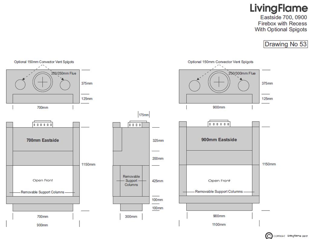
2 INSTALLATION GUIDELINES Living Flame Eastside Designer Gas Convector Fireplaces must be installed in accordance with these guidelines. For safe installation and operation, carefully read the following information. NOTE: Failure to follow these instructions may invalidate your household insurance and the fireplace warranty. It may also cause a malfunction or damage to the fireplace, possibly causing injury and / or property damage. Specifications may change without notice. OWNER 1. Fireplace Features Gas Rating Inputs 2. Eastside Overview Eastside Fires are Supplied With Eastside Configurations Drawing Number 62 Part Two 3. Dimensions 1200mm Standard Drawing Number 43 Part Two 1500mm Standard Drawing Number 44 Part Two 1200mm with Screen Recess Drawing Number 53 Part Two 1500mm with Screen Recess Drawing Number 54 Part Two 0700/0900mm Standard & Screen Recess, Plan View Drawing Number 63 Part Two 1200/1500mm Standard & Screen Recess, Plan View Drawing Number 63a Part Two 1800/2000mm Standard & Screen Recess, Plan View Drawing Number 64 Part Two 2400/3000mm Standard & Screen Recess, Plan View Drawing Number 65 Part Two 4. Location 5. Your safety and protection 6. What to do if you smell gas 7. Operating Instructions Electronic two stage with auto spark ignition 8. Guarantees
3 GASFITTER 1. Gas Rating Inputs 9. Ventilation 10. Gas Connection 11. Gas Supply 12. Test pressures 13. Testing 14. Controls 15. Flueing 16. Installation Fully Adjustable Bend and Adjustable Strap Drawing Number 4 Part 2 Spigot Plate, Cowl and Windskirt Drawing Number 4a Part 2 Roof Clearances Cowl & Flue Refer Drawing Number 67 Part 2 Cowl Height Clearance Drawing Number 68 Part 2 Flue Offset Drawing Number 69 Part 2 Installation of flexible ducting Drawing Number 59 Part 2 Framing and Enclosing Drawing Number 46 Part 2 Burner Air Balance No Hearth Drawing Number 47 Part 2 Burner Air Balance Cantilevered Hearth Drawing Number 48 Part 2 Burner Air Balance Cantilevered Stone Hearth Drawing Number 49 Part 2 Burner Air Balance Service Mesh Cover Drawing Number 50 Part 2 Rebate for Stone Lining (supplied by customer) Drawing Number 57 Part 2 Burner Air Balance/Screen Recess Cantilevered Hearth Drawing Number 58 Part Flue and chimney requirements 18. Flue height diagram Drawings 67, 68 Part Flue components diagrams and offset rules Drawings 4, 4a, 69 Part Burner Types Drawing Number 56 Part Routine service BUILDER 22. Angle of mantel Drawing Number 52 Part 2 ELECTRICIAN 23. Electrical 24. Wiring diagrams Drawings 9, 20, 21, 39, 61 Part 2
4 DRAWINGS contained in part two. 4 Bend and bracket 4a 6a 6b Cowl and spigot plate Electronic burner control, TCAIS, SIT 836 Tandem Gas Valve Electronic burner control, TCAIS, SIT 843 Sigma Gas Valve 9 Electronic burner control valve, testing coils 20 Electric control switching and wiring layout 21 Power supply system, wall switching 39 Eastside electronic burner control wiring layout 43 Eastside 1200mm dimensions 44 Eastside 1500mm dimensions 45 High Temperature cladding 46 Eastside cladding 47 Eastside burner air balance without hearth 48 Eastside burner air balance with cantilevered hearth 49 Eastside burner air balance with cantilevered stone hearth 50 Eastside burner air balance with cantilevered stone hearth and service mesh 51 Eastside with a 50mm rebate and loose stone lining or brick slips liner 52 Eastside angle of mantel 53 Eastside 1200mm plasma dimensions 54 Eastside 1500mm plasma dimensions 56 Burners, strip and full 57 Burner air balance without a hearth 58 Burner air balance with a cantilevered hearth 59 Burner air balance showing boots and grills 59a Screen Recess Convection Air 60 Eastside plasma with a 50mm rebate and loose stone lining or brick slips liner 62 Eastside model configurations 63 Eastside 0700mm and 0900mm, standard and plasma, plan view 63 Eastside 1200mm and 1500mm, standard and plasma, plan view 64 Eastside 1800mm and 2000mm, standard and plasma, plan view 65 Eastside 2500mm and 3000mm, standard and plasma, plan view 66 Eastside number of flues and burners reference 67 Flue to roof clearances 1 68 Flue to roof clearances 2 69 Eastside flue offset
5 FIREPLACE FEATURES Dual radiant and convected heat, Fully electronic safety control system with auto spark, Unique Living Flame diffuser burner fire, No products of combustion, (Co2, Co, Nox2) into the room, Natural convection, Totally clean room air, No added moisture into the room, Alumni steel construction for heat resistance and a longer lifetime, Extended heat surface heat exchanger to maximise convected heat, Natural gas or home delivered bottled gas (LPG) fuel options, Fire Sure Lifetime Body Guarantee, Fire Sure Lifetime Burner Assembly Guarantee, One Year Control Assembly Cover, One Year Labour Cover, ALL EASTSIDE CONFIGURATIONS TECHNICAL SHEET Gas rating inputs for each model shown Full Burner - NG Strip Burner - NG 1200mm mm mm 2 x 38 2 x mm 2 x 55 2 x mm 2 x 55 2 x mm 2 x 70 2 x 70
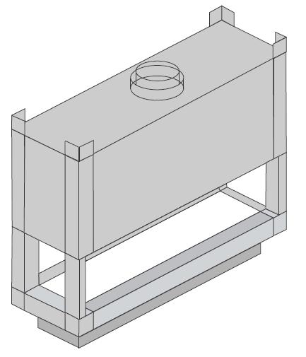
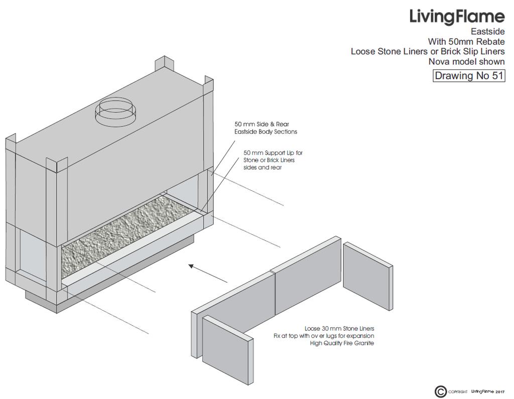
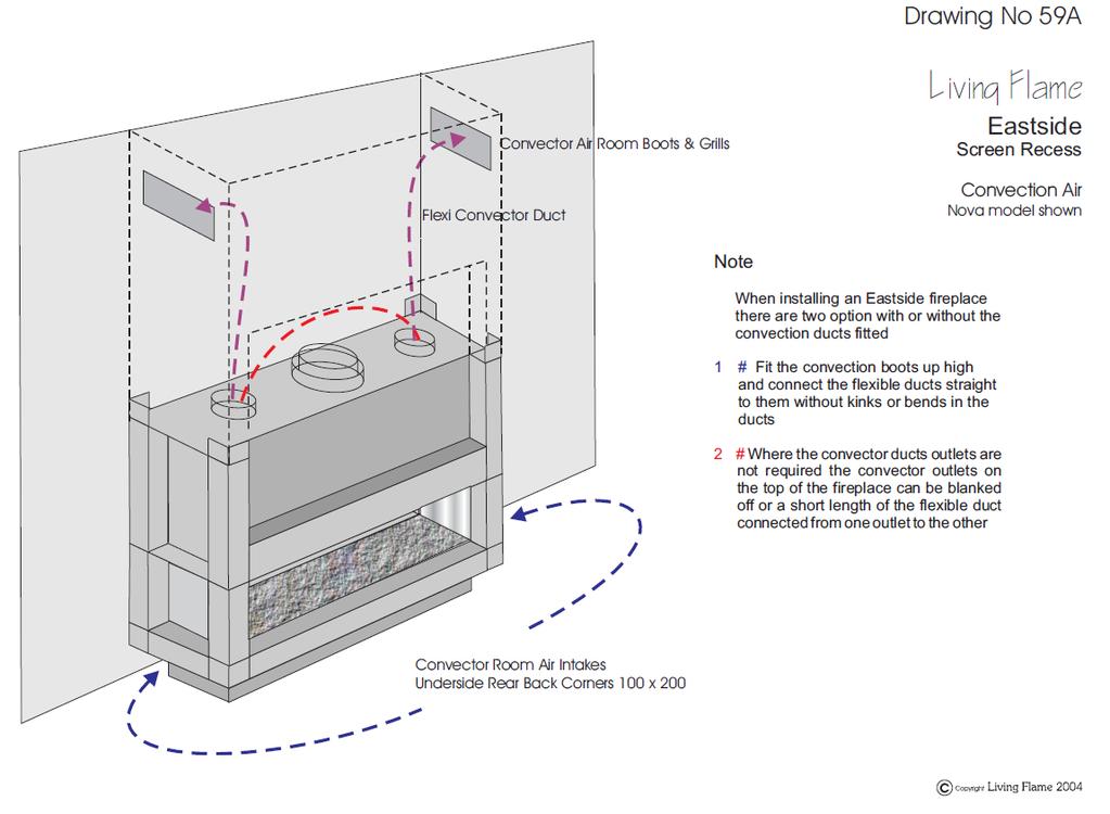
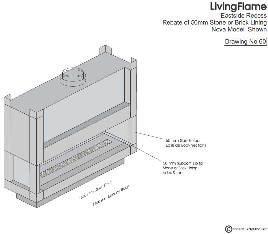
6 EASTSIDE FIREPLACE SERIES OVERVIEW Eastside Fireplaces are available in a number of configurations to suit your interior and the design you wish to achieve. EASTSIDE MODEL CONFIGURATION DESCRIPTION Niche left hand glass Corner One short glass side, one open long side, polished stainless steel back and side Niche right hand glass Corner One short glass side, one open long side, polished stainless steel back and side Nook Through wall One long glass side, one long open side, polished stainless steel short sides Nova Inbuilt Open long front, polished stainless steel back and sides Euro Vista left hand opening Vista right hand opening Quattro Three sided parallel Three sided divider Three sided divider Four sided free standing Open long front, two short glass sides, polished stainless steel back One open long side, one glass long side, one glass short side, one polished stainless steel back One open long side, one glass long side, one glass short side, one polished stainless steel back One open long side, one glass long side, two glass short sides EASTSIDE FIREPLACES ARE SUPPLIED COMPLETE WITH: main fire body, tempered glass panels and polished stainless steel panels as per the fires configuration, gas burner as selected, electronic two stage safety controls, effect as selected, finned convector hood, Optional flexible ducts, air outlet boots and grills - refer to drawing no 59. THIS FIREPLACE DOES NOT COME WITH ANY FORM OF FINISHING, IE: TILES, GRANITE ETC. OPTIONAL Fire may be supplied ready for brick lining if required. Refer to drawing no s 51 and 60.
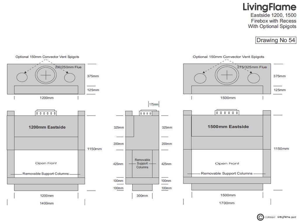
7 DIMENSIONS 1200mm Dimensions Refer drawing no mm Plasma Dimensions Refer drawing no mm Dimensions Refer drawing no mm Plasma Dimensions Refer drawing no mm and 0900mm Standard and Plasma, Plan View Refer drawing no mm and 1500mm Standard and Plasma, Plan View Refer drawing no 63a 1800mm and 2000mm Standard and Plasma, Plan View Refer drawing no mm and 3000mm Standard and Plasma, Plan View Refer drawing no 65 Cladding Refer drawing no 46 Number of Flues and Burners Reference Refer drawing no 66 LOCATION The fireplace should be located: Out of high traffic areas; Out of strong draughts; Away from furniture; Where the flue system can be correctly installed without damaging the structure of the building, checking that the flue vent and its shielding will not interfere with any structural timberwork; Where there is sufficient access for safe operation and maintenance; Where there is a flat and level surface; Where there is sufficient flue vent clearance around the flue in relation to doors or windows; Where there is access to a gas line or the gas line can be brought to the fireplace in accordance with ASNZS5601; Where there is access to an electrical supply for the electrical control system to be connected to; Where there is unobstructed adequate ventilation to allow correct combustion and operation of the fireplace; Where the fireplace can be used to optimise the radiant heat given off by the fireplace; These fires do not require a hearth.
8 YOUR SAFETY AND PROTECTION A fireguard to BS Standard 6539 or 6778 should be used for the protection of young children, the elderly and infirm. Do not store or use flammable vapours or liquids in the vicinity of this fireplace or any other gas appliance. Do not place combustible materials around the fireplace. Know where your gas shut off valves are located. WHAT TO DO IF YOU SMELL GAS Open windows; Do not try to light any gas appliance; Do not use any electrical appliance or switches; Do not use the telephone in your home; Turn off the gas supply to your house at the gas meter shut off valve, or the shut off valves at your gas bottle(s) location; Call your local gasfitter from a neighbour s house.
9 OPERATING INSTRUCTIONS ELECTRONIC TWO STAGE WITH AUTO SPARK IGNITION CONTROL OPERATION Check gas supply is turned ON. Check power supply is turned ON. START UP Turn both the on / off switch and the high / low Switch to the ON position. After the controller has completed a safety check (for some controllers this will take approximately 8 10 seconds, others may take seconds), The auto spark ignition will start and a clicking noise will be heard. The gas valve will open, the pilot will establish and the main burner will light. If the pilot fails to light the gas supply will be shut off after 8 seconds. Turn the control system to the off position and wait seconds before restarting the fire. Note: If the gas line has been interrupted or when first lighting the fire, it may be necessary to follow the above start up sequence several times. HIGH / LOW FLAME Once the fire has reached full glow and temperature, the high / low switch may be turned off to give the low fire effect. For high flame just turn the room switch back to on. SHUT OFF Turn the on / off room switch to the off position and the control system will shut off the pilot and main burner. SAFETY SHUT OFF The Electronic Control System will automatically shut down should the pilot be interrupted or the pilot fail to light. To re-set the control system, turn the room switch to the off position and wait seconds before the fire can be re-started. If the system fails to light after several attempts, call for a registered Living Flame Maintenance Engineer or Living Flame Auckland for your nearest registered service organisation.
10 Living Flame Expressed Guarantee January 2006 Eastside Convector Fireplace bodies are constructed for a minimum working life of 15 years when installed in compliance with ASNZS5601, C1 Outbreak of Fire and manufacturer s installation, operating and maintenance instructions. Fire Sure Lifetime Body Guarantee This is a Fire Sure Lifetime Replacement Guarantee that covers the fireplace body manufactured by Living Flame Fires and only covers the replacement of the fire body where an irreparable defect, due to material or manufacturing failure, occurs within the lifetime of the fire. The Fire Sure Lifetime Body Guarantee does not cover faults caused by incorrect installation, incorrect commissioning or misuse, and the fire should be installed and maintained in compliance with the guarantee and all conditions of the guarantee fulfilled. Fire Sure Lifetime Burner Assembly Guarantee This is a Fire Sure Lifetime Replacement Guarantee that covers the fire burner tray manufactured by Living Flame Fires and only covers the replacement of the fire burner tray where an irreparable defect, due to material or manufacturing failure, occurs within the lifetime of the fire. The Fire Sure Lifetime Assembly Guarantee does not cover faults caused by incorrect installation, incorrect commissioning or misuse, and the fire should be installed and maintained in compliance with the guarantee and all conditions of the guarantee fulfilled. One Year Control Assembly Cover This is a One Year Replacement Guarantee that covers the control parts used in the manufacturing of a Living Flame Fire. The manufacturer only covers the replacement of a control part where an irreparable defect, due to material or manufacturing failure, occurs within the first year from date of supply by Living Flame. One Year Labour Cover This is a One Year Guarantee covering the normal labour charges required to replace components of a Living Flame Fire should a part fail in its first year of service. The One Year Guarantee does not cover faults caused by incorrect installation or commissioning. The refund of associated labour charges are based on our schedule of costs listing services of parts to be charged for, time allotted and costs allowed including travel, when carried out by an approved Living Flame serviceperson. Travel is only covered within a 25km radius from either Living Flame Ltd in Auckland or our local distributor. The fire has to have been installed and maintained in compliance with the guarantee and all conditions of the guarantee must have been fulfilled. Exclusion From Guarantee This Fireplace Replacement Guarantee excludes any costs associated with the removal or replacement on site of the fireplace at the owners request, required for finishing work or refurbishment work to the fireplace, surround, chimney, flue or gas line testing or recertification. This guarantee is only valid when the fire has been installed in New Zealand.
11 Living Flame Expressed Guarantee contd. January 2006 Installation Living Flame Fireplaces must be installed to comply with: New Zealand Standards and Building Codes where relevant; Australia & New Zealand Standards 5601 Installation Gas Code; Living Flame Installation Instructions; Living Flame Operating Instructions; Living Flame Maintenance Instructions. Living Flame Fireplaces must be installed free from dampness and free from corrosive elements. Living Flame Fireplaces must be installed with an unrestricted flue or chimney. Living Flame Fireplaces must be installed by a suitably qualified person and a certificate of compliance must be made by a Registered Certifying Engineer under the New Zealand Gas Act. Guarantee and Warrantee Validity Guarantee claims will only be considered when completed by a Living Flame approved serviceperson in accordance with Living Flame procedures. Operating Living Flame Fireplaces must be operated in accordance with Living Flame Operating Instructions. Living Flame Fireplaces should be used only for the burning of gas fuels: Natural Gas, Liquid Petroleum Gas or Propane Gas. The type of gas to be used should be specified at the time of ordering the unit. Living Flame Fireplaces must only be operated with a Living Flame Gas Insert Fire that has been commissioned to Living Flame s Commissioning Instructions. Maintenance Living Flame Fireplaces must be maintained, cleaned and re-commissioned annually as should all gas appliances. Domestic Users Living Flame Fireplaces should be inspected, cleaned, serviced and re-commissioned at least once yearly throughout the lifetime of the fire to maintain the guarantee. Commercial Users Living Flame Fireplaces should be inspected, cleaned, serviced and re-commissioned at least twice yearly throughout the lifetime of the fire to maintain the guarantee. THIS GUARANTEE SHOULD BE KEPT IN A SAFE PLACE ALONG WITH THE OPERATING INSTRUCTIONS.
12 VENTILATION Fully Sealed Home Adequate ventilation for the fireplace must be provided in accordance with ASNZS5601 and the Manufacturer s Instructions. This fireplace has also been designed to draw room air into the fireplace and to complete combustion. Living Flame has carried out extensive research and testing into the correct ventilation for an open gas fireplace. The blocking or modifying of any of the airways of the fireplace in anyway could create a hazardous situation of overheating, poor combustion or poor ventilation. The requirements for an open natural draught fireplace in a fully sealed home, is for fixed ventilation to be fitted to supply makeup air with an open area equal to 100mm x 100mm for every 10Mjl that the gas fireplace is gas rated at. As a rule of thumb you will find that the size of the grille required will closely match the cross sectional area in m² of the fireplace s natural draught flue. The air flow rate through the ventilation grille is at a very low velocity, approximately 2Pa with an air flow of between 250m³-1200m³/hr depending on the size of the fireplace Semi Sealed Home Although the requirements are the same for a semi-sealed home, a more common sense approach to ventilation is taken. If the home has multiple leakage points (i.e. range hoods, garage doors, and gaps under doors) this may be factored in. If venting is required in a semi-sealed home, it could also be provided between internal walls or into the ceiling space. Bedroom Ventilation When installing a gas appliance into a bedroom VENTILATION MUST BE PROVIDED. This can be fixed or mechanical ventilation (interlocked with the fireplace operation.) Ventilation should be created from a fresh air environment. Open Plan - Combined Lounge, Bedroom Ensuite A Gas Fireplace located in an open plan combined Lounge, Bedroom ensuite area must follow: The gas fireplace must not be open to the ensuite side The gas fireplace must be fitted with full gas and flame supervision controls electronic or manual Adequate makeup air ventilation must be fitted in the form of a passive vent or vents equaling the fireplace flue draught requirements and any extractor requirements for ventilation system that may be installed in the same open plan combined area. The passive makeup air ventilation should be fitted into a free air vented ceiling space or fitted through the ceiling and roof to outside free air. Mechanical ventilation damper if fitted to the makeup air (as in Eco Houses) must be mechanically and electrically interlocked with the gas fireplace control safety system so that in the case of the damper failure the gas fireplace remains inoperable The gas fireplace must be draught tested with a draught gauge then any extractors system, air conditioning systems or heat pumps located in the open plan lounge, bedroom ensuite area be turned on. The systems must have no9 effect on the operation and operational flue draught of the gas fireplace Mirrors for safety must not be placed above a gas fireplace or open fireplace
13 GAS CONNECTION A gas certificate must be given for the installation, connection and associated flue vent system. All installation work should be carried out by a suitably trained and qualified person to comply with installation code ASNZS5601 and the manufacturers instructions and then certified by a Craftsman Gasfitter. Before installation commences, check the data plate on the fire to verify that the fire is set up to suit your type of gas supply. Field conversion to suit a different gas is not always practical. This fireplace is supplied with a 10mm soft copper connection mounted at the rear or the side of the fireplace, depending on configuration. A gas line capable of supplying a minimum of 100mj per burner should be brought to the fireplace with a 10mm soft copper tail. This is to be connected to the 10mm soft copper pipe. Other systems of connection may be used in accordance with ASNZS5601.
14 GAS SUPPLY Inlet Standing Pressure Set Up Pressure NATURAL GAS 2.0 kpa HIGH 1.0 kpa LOW 0.5 kpa U/LPG PROPANE 3.0 kpa HIGH 2.5 kpa LOW 1.5 kpa Maximum Inlet Pressure 6.0 kpa If inlet pressure exceeds 6.0 kpa, then damage will occur and may result in a hazardous condition. TEST PRESSURES Both the gas inlet and outlet test nipples are located on the electronic gas control valve. Values are shown in section 11. TESTING The fire outlet pressures have been preset in the factory, but should be reset when commissioning. To adjust: Turn off the fire and loosen the test nipple screw; Fit 6mm tube and test gauge securely; Turn on the fire, check pressure settings on high and low; Adjust control valve setting where required (refer to the Rating Plate for correct adjustment and settings); Turn off the fire, remove the gauge and tube. Secure the test nipple screw. In transit items of the burner or fire may become loose or pipe work may move, it is important to check all joints are gas tight and that all parts are located and operating correctly Final test with gas detector
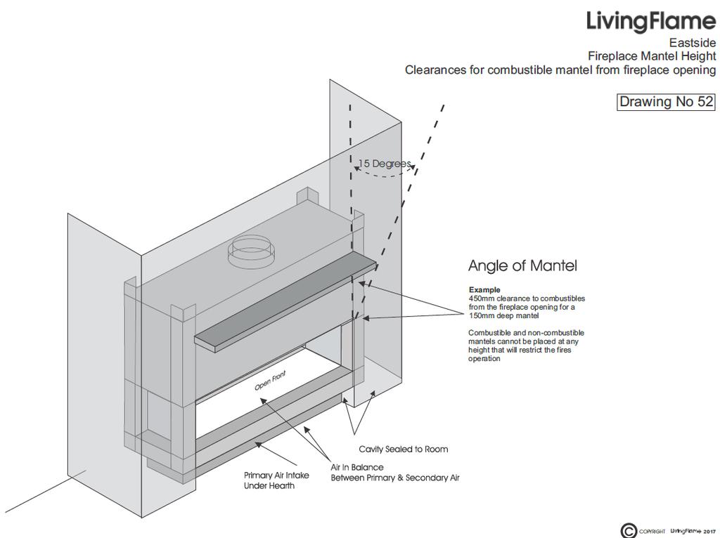
15 CONTROLS Customer Requirements: Show customer the operation of the appropriate control system. Ask them to operate it. Ensure the customer fully understands the control system and that they can operate it satisfactorily. FLUEING This fireplace must be vented to outside atmosphere. Flueing must be in accordance with the ASNZS5601 and all local body bylaws. Flue vent must be unrestricted. The flue vent should be checked for correct height and location in relation to other objects in close proximity (refer to drawing no s 67 and 68). Stand the fireplace in its proposed position, taking care to observe the minimum clearances shown. Flues must be sealed to prevent damage from water or products of combustion leakage. Flues should be inspected and tested annually. Power Flues If a power flue is needed then ref to the Power Flue manual for installation instructions and wiring diagrams.
16 INSTALLATION In New Zealand every home is different from the next. guidelines for installation only. Therefore, these are general A gas certificate must be completed at the finish of any installation of a gas appliance, flue system or gas pipework. Flue planning should be checked for correct height and location in relation to the roof and other objects in close proximity. Refer drawings 67 and 68. A gas connection should be brought into the fireplace, sized for a capacity of 100 mj/hr per burner to provide spare capacity in the gas line. Pressure test gas lines before connection to the fire. This fire will require electricity to operate. 2m lengths of cable are supplied with the fire. An electrician is then required to run these cables to where you choose to have your wall switches. Your electrician will supply the switching. Install the fire into position, level and fix. This fire can be installed directly onto a wooden floor. Connect a 10mm gas line from the fireplace to the gas supply line with a copper reducer and silfos joint (do not use a flare or gland fitting). Install flue components as required. If offsets are required, they should be installed with a minimum rise of not less than 10 degrees from the horizontal and should be bracketed to support the flues weight. Refer drawing no s 69 and 4. A spigot plate can be ordered for the top of the chimney or an appropriate roof seal or spigot cap can be provided by the installer. The spigot plate is then fixed to the top of the chimney and fixed to the liner becoming the top bracket. OR The roof seal is then tightly secured over the flue and sealed from the weather. Trim flue and galvanised liner to same length and slip on anti-downdraught cowl and windskirt. In exposed areas, the cowl should be fixed onto the outside liner. On completion of the fire installation, the flue should be inspected by the certifying person, in compliance with the New Zealand Standards, before cladding is fitted. Turn on gas supply and bleed air from the lines. Commission fire, smoke test, set flame height and combustion test. Refer drawing no 4a to see a spigot plate and a cowl. Some variations to these guidelines may be needed. If you have any doubts, please do not hesitate to contact Living Flame Fires for advice on installation.
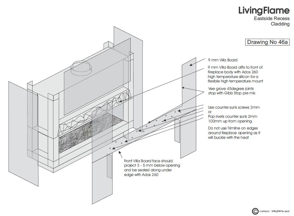
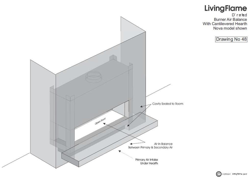
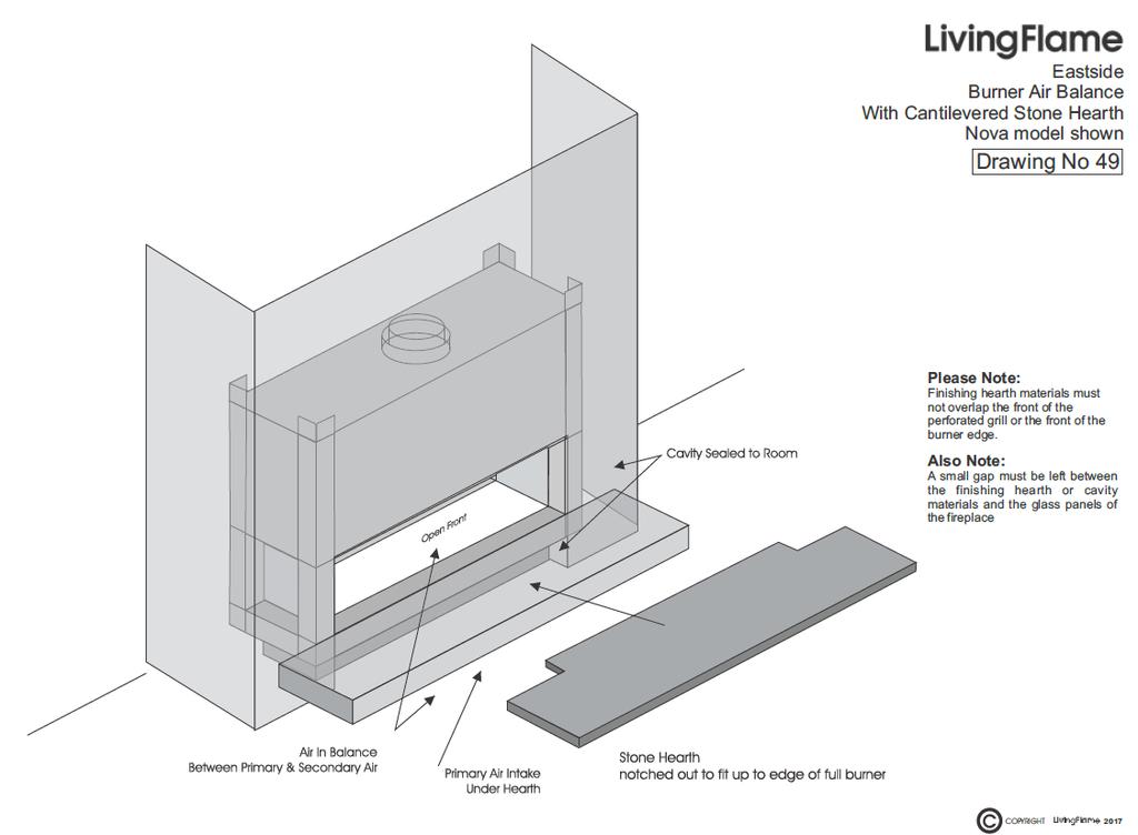
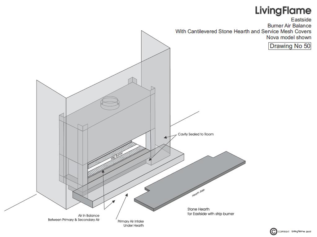
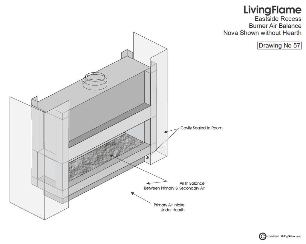
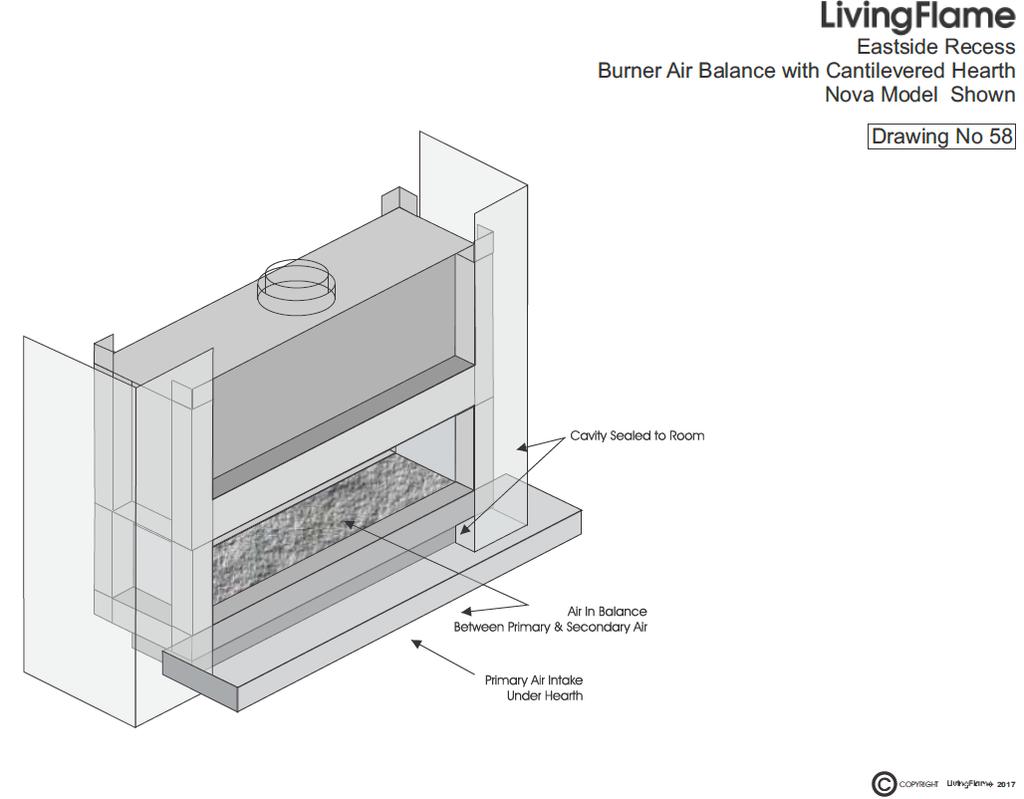
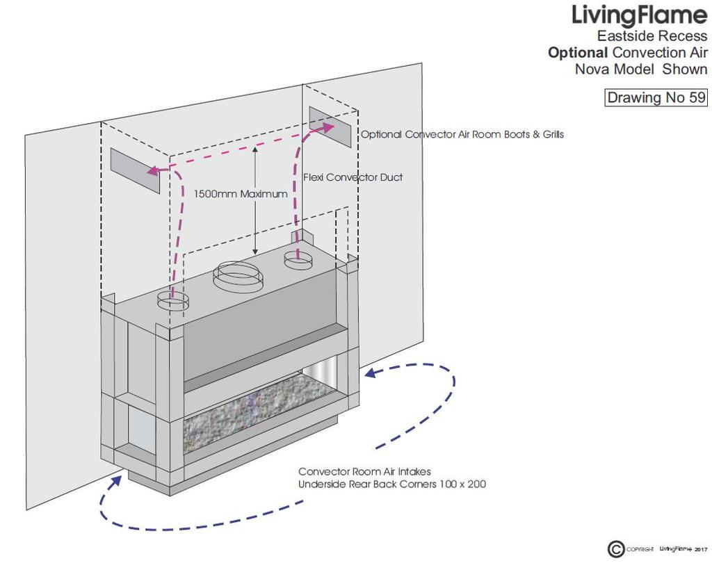
17 INSTALLATION OF FLEXIBLE DUCT AND FRAMING AND ENCLOSING INSTALLATION OF FLEXIBLE DUCT Supplied with your Eastside fireplace are two plastic air boots, two plastic grills and one length of 150mm insulated flexible duct. The air boots are installed at a high level around the fireplace, pinned into the framing. The flexible ducting is then divided into two sections, one for each boot. One end of the ducting is connected to the boot and the other to the convector outlet. Cut through the cladding and push the grill into place in the plastic air boot. Care should be taken not to kink the flexible ducting. Refer drawing no 59. TIMBER - FRAMING All Eastside fireplaces are supplied with framing mounting lugs. Framing lugs are designed for 100mm x 50mm timber. Framing weight should be taken by the ceiling joists and should exert no force onto the Eastside fireplace. CLADDING ENCLOSING DO NOT USE SLIM LINES, METAL OR PLASTIC AROUND THE OPEN FRONT OF THE FIREPLACE. Living Flame suggest that the fire is clad in 9mm Villa board or similar. This gives a smooth top edge. It can then be screwed or bonded to the framing and fireplace. The cladding can then be stopped and finished. Care should be taken to avoid excess plaster and dust settling into the fireplace and onto surrounding surfaces. Refer Drawing Number 46. FINISHING THIS FIREPLACE DOES NOT COME WITH ANY FORM OF FINISHING, IE: TILES, GRANITE ETC. Marble, slate, granite, tiles etc., can be affixed to the bottom fascia edge plate, to give the effect desired. Tiles etc., should be butt-jointed to give the best finished appearance. 3 4mm holes may be drilled in the fascia plate of the Eastside fireplace to provide a key for fixing compounds and adhesives if required. Do not block the vent holes on the underside of the bottom fascia edge plate. These are required to ensure the correct operation of your fire. Refer Drawing Numbers 47, 48, 49, 50, 57 and 58.
18 FLUE AND CHIMNEY REQUIREMENTS DESIGN A flue or chimney is required for these Eastside Fireplaces. All flues must be double skinned with a 25mm minimum airspace. Flue materials should be a stainless steel inner flue with sealed joints, and a galvanised outer with airspace liner. LINER INSTALLATION Flue outer airspace should be a minimum of 25mm from any combustible material. Flues may be offset at not less than a 10 angle from the horizontal. Flues should not be restricted in any way. Flues should be bracketed to take their own weight. Flues must have an anti-downdraught rain and wind cowl fitted. Roof flashing and seals should be the appropriate type for the roof. HEIGHT The minimum effective height of the flue shall be at least 3.6m. Flues or chimneys should rise until there is a 2.5m clearance horizontally from any part of the roof or other obstructions. The flue then rises a further 500mm vertically from the clearance point, giving the correct height and wind clearance. A Living Flame anti-downdraught cowl and windskirt should then be fitted. POWER FLUES If a power flue is needed then ref to the Power Flue manual for installation instructions and wiring diagrams. LIVING FLAME will be pleased to assist you or your architect with the design of the flue or chimney to achieve a result that functions correctly and has the desired appearance for the house.
19 FLUE HEIGHT DIAGRAM Refer Drawing Numbers 67 and 68. FLUE COMPONENTS AND OFFSET RULES Refer Drawing Numbers 4, 4a, 69
20 INSTALLATION OF FIXED LOG SET DIFFUSER BURNER Only the logs and embers supplied with this fire may be used on this fire and said logs and embers may not be used on any other brand of fire. The fire has a handful of the embers supplied lightly scattered over the fire bed blanket. Place the fixed log set on the ember bed. Gently settle the frame of the fixed log set into the embers, ensuring that the metal frame is not visible. When the fire is set correctly the flames should be peaking at approximately 75mm 100mm on high and 25mm 35mm on low. INSTALLATION OF COTSWOLD EFFECT DIFFUSER BURNER Only the Cotswold Stone and embers supplied with this fire may be used on this fire and may not be used on any other brand of fire. The fire has a handful of the supplied embers lightly scattered over the fire bed blanket. Gently settle the frame of the fixed Cotswold Stone set into the embers, ensuring that the metal frame is not visible. When the fire is set correctly the flames should be peaking at approximately 75mm 100mm on high and 25mm 35mm on low. INSTALLATION OF COTSWOLD STONE EFFECT STRIP BURNER Only the Cotswold Stones and embers supplied with this fire may be used on this fire and said Cotswold Stones and embers may not be used on any other brand of fire. The strip burner does not have a fire bed blanket The fire has embers filled to approximately 15mm deep over the fire strip length. Ensure that the embers are filled to the edge of the pilot frame but are not in or on the pilot. Place the Cotswold Stone effect evenly over the ember bed to a depth of approximately 25mm. Ensure that they are evenly distributed to create an even flame pattern. When the fire is set correctly the flames should be peaking at approximately 75mm 100mm on high and 25mm 35mm on low.
21 ROUTINE SERVICE Fireplaces in domestic situations need to be serviced yearly. Fireplaces in commercial situations need to be service six monthly. Check meter or cylinders Pressure drop test gas lines Inspect inbuilt fireplace Dismantle fireplace and inspect components Clean all components and body Check operation of controls and safety devices Check flue system is clear and clean Check flue vent Re-assemble fire Check ignition system. Perform lighting test, minimum 20 out of 20 Check injector and pressure settings Check fire effect, flame distribution and height Complete assembly Test flue vent system Check complete operation of the fire Final clean and dust Re-light all other gas appliances Re-demonstrate fireplace to owner to ensure owner has full understanding of the fireplace Sign off service sheet with owner
22 ANGLE OF MANTEL Refer drawing number 52 ELECTRICAL This fireplace, in order to operate, needs an external power supply. This model has an electronic flame rod safety device that when heated by the pilot flame, generates a micro amp supply, enough to operate the control of the main burner. The fireplace, when installed, should be electrically grounded in accordance with the electrical regulations. This fireplace is supplied with an electronic control system. The appropriate electrical and operating instructions for the control system should be enclosed. Fireplace to be fitted with a power flue ref to the Whisper Flue manual for installation instructions and wiring diagrams. WIRING DIAGRAMS Refer Drawings Numbers 6a, 6b,7, 9, 20, 21 39, 61
23
24
25
26
27
28
29
30
31
32 275/325mm Flue
33
34
35
36
37
38
39
40
41
42
43
44
45
46
47
48
49
50
51
52
53
54
55
56
57
58
Rhode Island PIT FIRES
 Rhode Island PIT FIRES HELLO from all of us at Living Flame THE RHODE ISLAND PIT FIRE RANGE So you want a little something special for your yard. We ve created these with you in mind (Besides, being inside
SG Burner Only
 SG 700-780-900-1100 Burner Only SG Gas Burner into a Warmington SI Wood Open Fire Installation Guide Only Warmington SI Open Wood Firebox. Warmington SG Gas Burner. Traditional Grate & Burner Pure Grate
Installation Manual EF5000 NZ
 Installation Manual EF5000 NZ Important: The appliance shall be installed in accordance with; Local gas fitting regulations Municipal building codes AS/NZS 5601.1.1:2010 Gas Installation Any other relevant
Gas Flare & Rail Burners Gas Flare & Rail Burners Installation Instructions
 Gas Flare & Rail Burners Gas Flare & Rail Burners Installation Instructions Gas Flare Rail Burner (Ash Pan ) Rail Burner (Grate ) OPTION 1 OPTION 2 and 3 Installation to Comply with NZS 5262 / 5261:2003
Installation Instructions Horizon Natural Draft Electronic Ignition Gas Fireplaces
 Installation Instructions Horizon Natural Draft Electronic Ignition Gas Fireplaces Installation Instructions Horizon Natural Draft Electronic Ignition 3 Sided Gas Fireplaces Natural Draft Electronic Ignition
Installation Manual EF5000 AUS & NZ
 Installation Manual EF5000 AUS & NZ This manual is ONLY for fires with a serial No. from 80600 to 80999. Important: The appliance shall be installed in accordance with; Local gas fitting regulations Municipal
Debonaire VIRAGE LH
 Debonaire VIRAGE LH 1200-1600-2000-2400- Custom Fire VIRAGE LH Gas Burner Installation Instructions Flue Liner Firebox Venting Non-Combustible Promina Board Cladding Burner NOTE: T.V. Option Available
THE INSTRUCTIONS IN THIS MANUAL APPLY TO KENT GAS FIRES. CONTENTS:-
 THE INSTRUCTIONS IN THIS MANUAL APPLY TO KENT GAS FIRES. THE MODELS COVERED ARE:- For use with Natural Gas:- KENT ESTATE NG, KENT ULTIMA NG For use with Liquid Propane Gas (LPG):- KENT ESTATE LP, KENT
SURE HEAT MANUFACTURING
 SURE HEAT MANUFACTURING Installation and Operating Instructions for NATURAL & L.P. GAS A.G.A. SINGLE & DUAL BURNER VENTED UNITS Model: RP (8,24,30)-N GO (8,24,30)-N GLO (8,24,30)-N WO (8,24,30)-N CO (8,24,30)-N
MODELS LFP4218/LFP6018 TOP VENT GAS FIREPLACE
 MODELS LFP4218/LFP6018 TOP VENT GAS FIREPLACE PFS APPROVED FOR NATURAL GAS OR PROPANE GAS Z21.50-2014 If your plans do not allow for the venting system as outlined previously in the installing chimney/vent
Contents. 19. Eastside Manhattan Fireplaces. 6. Thermoflow Design. 20. Custom Made Baskets & Inserts. 7. Thermoflow Convector
 2015.1 Contents 6. Thermoflow Design 7. Thermoflow Convector 10. Thermoflow Original Black 11. Thermoflow Intense 12 Thermoflow Excite 13 Thermoflow Allure 14. Eastside Designer Fireplaces 18 Eastside
IB1100 and IB850 Installation Manual AUSTRALIAN EDITION
 IB1100 and IB850 Installation Manual AUSTRALIAN EDITION Important: The appliance shall be installed in accordance with; This installation instruction booklet Local gas fitting regulations Municipal building
Dovre 250 Cast Iron Gas Stove
 Dovre 50 Cast Iron Gas Stove NATURAL GAS AND LPG INSTALLATION, SERVICING AND USER INSTRUCTIONS THIS PRODUCT IS FOR USE ONLY IN GREAT BRITAIN AND IRELAND These instructions are to be left with the customer,
INSTALLATION & OPERATING MANUAL
 MAGIGLO SERIES INSTALLATION & OPERATING MANUAL The Magiglo series of decorative fires are suitable to be installed into a masonry or approved prefabricated fireplace and are designed to operate with Natural
SPECIFICATION & INSTALLATION GUIDE FOR MASPORT LE4000 PROVINCIAL INSERT FIRE, NEW ZEALAND MODEL
 SPECIFICATION & INSTALLATION GUIDE FOR MASPORT LE4000 PROVINCIAL INSERT FIRE, NEW ZEALAND MODEL Manufactured in New Zealand by: GLEN DIMPLEX AUSTRALASIA LIMITED PO Box 58-473 Botany Auckland 2163 Ph: 0800
Debonaire DUPLO
 Debonaire DUPLO 1200-1600-2000-2400-2800 Custom Fire DUPLO Gas Burner Installation Instructions Flue Liner Promina Board Cladding Non-Combustible Firebox Venting Burner NOTE: TV Above option available
Pizza Oven with Stand
 Pizza Oven with Stand Cooks up to 3 pizzas at a time Use to cook a variety of food Easy clean vitreous enamel interior Model No. P0104 Powerful 22MJ/h stainless steel burner Viewing window and temperature
(manual control) (ezi-slide control) INSET COAL EFFECT GAS CONVECTOR FIRE V1/100/B INSTALLATION & USER INSTRUCTIONS
 (ezi-slide control) INSET COAL EFFECT GAS CONVECTOR FIRE V1/100/B INSTALLATION & USER INSTRUCTIONS") Model Number: V1/100/A V1/100/B (manual control) (ezi-slide control) INSET COAL EFFECT GAS CONVECTOR FIRE INSTALLATION & USER INSTRUCTIONS GB IE SUITABLE FOR USE ON NATURAL GAS (G20) AT 20mbar SUPPLY PRESSURE
Model Number: V1/100/A V1/100/B (manual control) (ezi-slide control) INSET COAL EFFECT GAS CONVECTOR FIRE INSTALLATION & USER INSTRUCTIONS GB IE SUITABLE FOR USE ON NATURAL GAS (G20) AT 20mbar SUPPLY PRESSURE
Twin Wall Installation Instructions And Maintenance Guide
 Twin Wall Installation Instructions And Maintenance Guide Please read all instructions before beginning your installation. Failure to install this system in accordance with these instructions will invalidate
5traxo INSTALLATION AND SERVICING INSTRUCTIONS MANDATORY REQUIREMENTS INSTALLATION
 5traxo Division of Legge Fabheat Ltd Longfield Road, Sydenham, Leamington Spa CV31 1XB Tel. (0926) 882233 Fax (0926) 450846 Registered in England No. 500091 Universal INSTALLATION AND SERVICING INSTRUCTIONS
IB850 and IB600 Installation Manual AUSTRALIAN EDITION
 IB850 and IB600 Installation Manual AUSTRALIAN EDITION Important: The appliance shall be installed in accordance with; This installation instruction booklet Local gas fitting regulations Municipal building
Studio 3 Steel 2, Glass Fronted with Log-effect fuel bed and Vermiculite lining STUDIO GAS FIRES
 Studio 3 Steel 2, Glass Fronted with Log-effect fuel bed and Vermiculite lining STUDIO GAS FIRES STUDIO GAS FIRES A Warm Welcome Nothing creates an inviting atmosphere quite like a Gazco fire. The centrepiece
INSTALLATION GUIDE NZ AU E
 GAS COOKTOP CG604DX & CG905DX models INSTALLATION GUIDE NZ AU 590447E 08.17 1 SAFETY AND WARNINGS Electrical shock hazard WARNING! Before carrying out any work on the electrical section of the appliance,
Wok Cookers Instruction Manual
 Wok Cookers Instruction Manual Part No. DC100-09 Single Burner Wok Cooker Part No. DC200-09 Double Burner Wok Cooker IMPORTANT It is IMPORTANT that you read these instructions carefully and understand
Evolve 951 & Product specification pages
 951 & 1250 Product specification pages SUPPORTING ASTHMA CARE Evolve Specification Evolve 951 Evolve 1250 Inbuilt power flued convection fan heater with electronic temperature control, timers, and remote.
INSTALLATION INSTRUCTIONS COMPACT GAS STOVE MODEL NUMBER 550
 INSTALLATION INSTRUCTIONS COMPACT GAS STOVE MODEL NUMBER 550 Before installation ensure that the local distribution conditions (identification of the type of gas and pressure) and the adjustment of the
Greenstar 12i/24i System
 USER INSTRUCTIONS & CUSTOMER CARE GUIDE Greenstar 12i/24i System WALL HUNG GAS-FIRED CONDENSING SYSTEM BOILER FOR SEALED CENTRAL HEATING SYSTEMS & INDIRECT FED DOMESTIC HOT WATER THIS BOILER IS USED WITH
Important: Appliance must be installed with a Rinnai approved flue system.
 Important: Appliance must be installed with a Rinnai approved flue system. This appliance shall be installed in accordance with: - Manufacturer s installation instructions - AS/NZS 5601 Gas Installations
16 Ultiflame Inset Electric Fire
 16 Ultiflame Inset Electric Fire B-1001645 Packing Checklist Electric Fire Remote Control Handset 2 x AAA Batteries Log Set Ember Ice Set Instruction Manual Fascia IMPORTANT PLEASE READ THESE INSTRUCTIONS
Patio Heater Model No. GM and GM
 Patio Heater Model No. GM124-003 and GM124-004 FEATURES: The ideal solution for extending the season for outdoor entertaining Maximum output 39.6 MJ/hr Direct ignition Adjustable heat output Safety tip-over
SOUTHWEST FIREBIRD MFG SONORAN UNVENTED Model 36/42/48
 SOUTHWEST FIREBIRD MFG SONORAN UNVENTED Model 36/42/48 INSTALLATION INSTRUCTIONS PREFABRICATED MODULAR MASONRY- UNVENTED SONORAN 36/42/48TO BE USED WITH UNVENTED GAS LOGS. SAVE THIS BOOK This book is valuable.
It is critical to maintain the Beech Oven and associated equipment on a regular basis, to avoid the possibility of a serious fire or malfunction.
 Maintenance Schedule.doc Page 1 of 12 2010-10-26 (C) Version: 1 Oven Maintenance If properly cared for, your Beech Oven will give you many years of trouble free operation. We recommend you consider adopting
Rinnai. Rinnai GAS SPACE HEATERS. Convector 417 Unflued Room Heater CUSTOMER S OPERATING INFORMATION AND INSTALLATION INSTRUCTIONS
 Rinnai Convector 417 Unflued Room Heater CUSTOMER S OPERATING INFORMATION AND INSTALLATION INSTRUCTIONS This appliance shall be installed in accordance with:- * Manufacturer s Installation instructions
Fully-automatic Gas tankless Water Heater USER'S MANUAL FOR MODEL EZ-101 ISO9001 certified
 Fully-automatic Gas tankless Water Heater USER'S MANUAL FOR MODEL EZ-101 ISO9001 certified Thank you for purchasing our fully-automatic gas-fired tankless water heater. Please completely read this Manual
THE INSTRUCTIONS IN THIS MANUAL APPLY TO MASPORT BOSTON (Flued) AND CALGARY (Flueless) GAS FIRES.
 AND CALGARY (Flueless) GAS FIRES.") THE INSTRUCTIONS IN THIS MANUAL APPLY TO MASPORT BOSTON (Flued) AND CALGARY (Flueless) GAS FIRES. THE MODELS COVERED ARE:- MG 3000 STD NG, and MG 3000 FLS NG for use with Natural Gas MG 3000 STD LP, and
THE INSTRUCTIONS IN THIS MANUAL APPLY TO MASPORT BOSTON (Flued) AND CALGARY (Flueless) GAS FIRES. THE MODELS COVERED ARE:- MG 3000 STD NG, and MG 3000 FLS NG for use with Natural Gas MG 3000 STD LP, and
MODEL 466 Radiant / Convector Gas Fire Black Beauty
 O W N E R G U I D E MODEL 466 Radiant / Convector Gas Fire Black Beauty This Owner Guide is intended to help you care for your Valor gas fire. Please read carefully before using your gas fire and keep
XANDER INSERT WOOD BURNER
 A division of Terry Young Ltd, New Zealand INSTALLATION INSTRUCTIONS for XANDER INSERT WOOD BURNER Clean Air Sub 1.0 Non Clean Air (Rural) 26 JUNE 2017 These instructions are for MASONRY installations
Stockton 7 & 8 Inset Convector Stove
 Stockton 7 & 8 Inset Convector Stove Installation Instructions MODELS: 7125/7126 For Use in Great Britain and Eire This product is suitable for use in the stated countries. To install the product in other
Decorative Fuel Effect Appliances
 Decorative Fuel Effect Appliances Technical Manual User and Installation Instructions for CUBB22US Available in Natural Gas. 1 Contents Section Pages 1 Unpacking 3 2 Installation Parameters 4 3 Installation
INSTALLATION INSTRUCTIONS
 INSTALLATION INSTRUCTIONS Gas Cooktop CG905DW models NZ AU www.fisherpaykel.com 590684B 11.14 1 Safety and warnings! WARNING! Electrical Shock Hazard Before carrying out any work on the electrical section
Operation & Installation Manual
 Operation & Installation Manual Rinnai Instantaneous Water Heater Model - IHF10 This appliance shall be installed in accordance with: Manufacturer s Installation Instructions Current AS/NZS 3500 & AS/NZS
LANDSCAPE BALANCED FLUE SPACE HEATER
 LANDSCAPE BALANCED FLUE SPACE HEATER INSTALLATION & OPERATING MANUAL The Landscape 1000 & 1600 are approved to be installed as a zero clearance firebox and are designed to operate on Natural Gas and Propane
Gas Fire Patio Heater Q9
 Gas Fire Patio Heater Q9 Instruction Manual Please read the manual BEFORE you unpack or install the fire TABLE OF CONTENTS Warning 3 Getting Started 4 What s Included 5 Assembly Procedures 6 Product Drawing
LANDSCAPE BALANCED FLUE SPACE HEATER
 LANDSCAPE BALANCED FLUE SPACE HEATER INSTALLATION & OPERATING MANUAL The Landscape 1000 & 1600 are approved to be installed as a zero clearance firebox and are designed to operate on Natural Gas and Propane
INSTALLATION GUIDE NZ AU D
 GAS COOKTOP CG905DW models INSTALLATION GUIDE NZ AU 590684D 08.17 1 SAFETY AND WARNINGS! WARNING! Electrical Shock Hazard Before carrying out any work on the electrical section of the appliance, it must
gas log fires freestanding & inbuilts
 gas log fires freestanding & inbuilts why choose Regency? An exceptional fire, custom elegance and controllable heat are just a few reasons to make a Regency fire part of your family. In 1979, I founded
OWNER GUIDE. Model 739 OPEN DECORATIVE GAS FIRE. (GC No )
") 5113426/01 OWNER GUIDE Model 739 OPEN DECORATIVE GAS FIRE (GC No. 32-032-54) THIS APPLIANCE IS FOR USE WITH NATURAL GAS (G20). WHEN CONVERTED USING CONVERSION KIT NO. 0595211 THIS APPLIANCE IS FOR USE
5113426/01 OWNER GUIDE Model 739 OPEN DECORATIVE GAS FIRE (GC No. 32-032-54) THIS APPLIANCE IS FOR USE WITH NATURAL GAS (G20). WHEN CONVERTED USING CONVERSION KIT NO. 0595211 THIS APPLIANCE IS FOR USE
Hurlcon Gas Fired Hot Water Boiler H120 & H150 S & B Models
 Hurlcon Gas Fired Hot Water Boiler H120 & H150 S & B Models INSTALLATION AND OPERATING INSTRUCTIONS HURLCON Manufacturing & Sales Pty. Ltd. A.B.N. 97 007 284 504 48 Hanna Street, Noble Park, VICTORIA.
Installation guide Compact 2
 Installation guide Compact 2 Models: RIBF2N/RIBF2L Standard frame Traditional frame Installer, please note: The gas and electrical plate of the unit is not required when attaching the traditional frame,
INSET LIVE FUEL EFFECT GAS FIRE
 600B741/02 OWNER S GUIDE MODEL BR650 VA (GC No. 32-032-39) INSET LIVE FUEL EFFECT GAS FIRE THIS APPLIANCE IS FOR USE WITH NATURAL GAS (G20) WHEN CONVERTED USING CONVERSION KIT NO.591149 THIS APPLIANCE
OWNER S GUIDE ETERNITY. MODEL 540C (GC No ) INSET BALANCED FLUE GAS FIRE
 INSET BALANCED FLUE GAS FIRE") 600B637/02 ETERNITY MODEL 540C (GC No. 32-032-19) INSET BALANCED FLUE GAS FIRE THIS APPLIANCE IS FOR USE WITH NATURAL GAS (G20) THIS APPLIANCE IS FOR USE IN THE UNITED KINGDOM (GB) AND THE REPUBLIC OF
600B637/02 ETERNITY MODEL 540C (GC No. 32-032-19) INSET BALANCED FLUE GAS FIRE THIS APPLIANCE IS FOR USE WITH NATURAL GAS (G20) THIS APPLIANCE IS FOR USE IN THE UNITED KINGDOM (GB) AND THE REPUBLIC OF
Greenstar 25Si/30Si USER INSTRUCTIONS & CUSTOMER CARE GUIDE
 USER INSTRUCTIONS & CUSTOMER CARE GUIDE Greenstar 25Si/30Si WALL HUNG GAS-FIRED CONDENSING COMBINATION BOILER FOR SEALED CENTRAL HEATING SYSTEMS & DOMESTIC HOT WATER THIS BOILER IS USED WITH NATURAL GAS
MAJESTIC OUTDOOR GAS FIREPLACE
 MAJESTIC OUTDOOR GAS FIREPLACE To suit Models: ODGSR36ANAU & ODGSR36APAU Gas Types: Natural Gas (NG) or Propane (LPG) CUSTOMER INSTALLATION AND OPERATING INSTRUCTIONS Thank you for purchasing a Majestic
INTERNATIONAL GAS CONVECTOR BOX
 INTERNATIONAL GAS CONVECTOR BOX For Zero Clearance Installations THIS MANUAL CONTAINS INSTRUCTIONS FOR ASSEMBLY AND INSTALLATION Please read this entire manual before you assemble, install and use the
GB IE INSTALLATION & USER INSTRUCTIONS. Model Number: V1/300/B (ez-slide control) HIGH EFFICIENCY INSET COAL EFFECT GAS CONVECTOR FIRE
 HIGH EFFICIENCY INSET COAL EFFECT GAS CONVECTOR FIRE") Model Number: V1/300/B (ez-slide control) HIGH EFFICIENCY INSET COAL EFFECT GAS CONVECTOR FIRE INSTALLATION & USER INSTRUCTIONS GB IE SUITABLE FOR USE ON NATURAL GAS (G20) AT 20mbar SUPPLY PRESSURE These
Model Number: V1/300/B (ez-slide control) HIGH EFFICIENCY INSET COAL EFFECT GAS CONVECTOR FIRE INSTALLATION & USER INSTRUCTIONS GB IE SUITABLE FOR USE ON NATURAL GAS (G20) AT 20mbar SUPPLY PRESSURE These
SIME FORMAT WALL HUNG BOILERS MODEL 34i AND MODEL 34e. cod A
 cod. 6272262A GENERAL DATA Heating Data Heat Output Input (Adjustable) (Adjustable) Format 34i 11.2 34KW 45 145MJ/hr Format 34e 11.2 34KW 45 145MJ/hr General Specifications FORMAT 34i 34e Main burner injectors
INSTALLATION INSTRUCTIONS
 INSTALLATION INSTRUCTIONS Gas-on-glass cooktop CG302D, CG451D, CG603D, CG604D, CG752D, CG903D & CG905D models GB IE IN 590657A 02.14 1 SAFETY AND WARNINGS 3 WARNING! Electrical shock hazard Before carrying
Installation & Service Instructions
 Part No. 966/9350/1 02 Potterton Housewarmer Illusion ASD - G.C. NO. 37 590 16 966 Inset DGF with ILLUSION FACIA Potterton Housewarmer Stratton ASD - G.C. NO. 37 590 17 966 Inset DGF with STRATTON FACIA
Manual. G51 Surefire. Owners & Installation PLEASE KEEP THESE INSTRUCTIONS FOR FUTURE REFERENCE. Models: G51-NG G51-LPG
 Owners & Installation Manual LISTINGS AND CODE APPROVALS These gas appliances have been tested in accordance with AG 103, NZS 5262 and have been certified by the Australian Gas Association for installation
gas & wood fire collection
 gas & wood fire collection www.regency-fire.co.nz LIFETIME GAS FIRE W A R R A N T Y Why Choose Regency? An exceptional fire, custom elegance and controllable heat are just a few reasons to make a Regency
INSTALLER AND OWNER GUIDE
 5110831/03 INSTALLER AND OWNER GUIDE Model 808 Electric Heater This guide is intended to help you install and care for your Baxi Fires Division electric heater. Please read carefully before installing
Operation guide Evolve 950
 Operation guide Evolve 950 Important: Appliance must be installed with a Rinnai approved flue system. This appliance shall be installed in accordance with: Manufacturer s installation instructions AS/NZS
PRACTICAL USER S GUIDE FOR THE DIMPLEX ELECTRIC FIREPLACE WITH REMOTE CONTROL
 PRACTICAL USER S GUIDE FOR THE DIMPLEX ELECTRIC FIREPLACE WITH REMOTE CONTROL Serial Number Model Number CAT Number Quality checked by: Valued Customer, We are pleased that you have chosen to purchase
HUNTER HAWK 4 MKII GAS STOVE
 HUNTER HAWK 4 MKII GAS STOVE User Instructions Please leave this instruction booklet with the user after the installation is complete. Leave the system ready for operation and instruct the user in the
EMBERGLOW CLASSIC RADIANT CONVECTOR GAS FIRE. Installation and Maintenance Instructions
 , EMBERGLOW CLASSIC RADIANT CONVECTOR GAS FIRE Installation and Maintenance Instructions Hand these instructions to the user Model No. FEMC00MN is for use on Natural Gas (G20) at a supply pressure of 20
Specification and Installation Instructions
 This manual contains instructions for assembly and installation Please read this entire manual before you assemble, install and use the Kemlan Horizon Lowline Series. KEMLAN HORIZON LOWLINE SERIES 700
gas log fires freestanding & inbuilts
 gas log fires freestanding & inbuilts why choose Regency? An exceptional fire, custom elegance and controllable heat are just a few reasons to make a Regency fire part of your family. In 1979, I founded
SURE HEAT. Installation and Operating Instructions for NATURAL & L.P. GAS VENT FREE SYSTEM
 SURE HEAT Installation and Operating Instructions for NATURAL & L.P. GAS VENT FREE SYSTEM Model: SCVFMR18, SCVFMR 24/21, SCVFMR30 (LP or NG Versions) DANGER: FAILURE TO FOLLOW THESE INSTRUCTIONS CAREFULLY
Installation instructions Jetmaster Mark 4 Gas Log
 Installation instructions Jetmaster Mark 4 Gas Log with Millivolt Control Installation instructions Jetmaster Mark 4 Gas Log Jetmaster gas logs are fuel effect appliances intended for use in a fireplace
Gas Fireplaces FEATURING
 Gas Fireplaces FEATURING Product Overview PRODUCT SPECS MODEL 564 GS2 (Clean Face) Dancing-Fyre Ember-Fyre Diamond-Fyre 864 GS2 (Clean Face) 864ST GS2 Mj Input High - NG/LPG 21.6 35 35 35 31 39.5 Low NG
INSTALLATION AND OPERATION INSTRUCTIONS FOR ZERO CLEARANCE AND INSERT UNITS
 INSTALLATION AND OPERATION INSTRUCTIONS FOR ZERO CLEARANCE AND INSERT UNITS ZECL-26-2923-BG ZECL-30-3226-BG ZECL-33-3624-BG ZECL-39-4134-BG ZECL-2939-BG INSERT-26-3825-BG INSERT-30-4026-BG INSERT-33-4230-BG
STRATA BATTERY IGNITION RADIANT CONVECTOR GAS FIRE
 STRATA BATTERY IGNITION RADIANT CONVECTOR GAS FIRE Installation, Maintenance & User Instructions Hand these instructions to the user Model No s FORS**EN are for use on Natural Gas (G20) at a supply pressure
GrateGlow THE ALL NEW CAPITAL COLLECTION. G20 at 20mbar convertible to G31 at 37mbar. For use in GB and le. Users Instructions
 GrateGlow A CARVER GROUP COMPANY --..--... THE GAS CONSUMERS' COUNCIL (GCC) IS AN INDEPENDENT ORGANISATION WHICH PROTECTS THE INTEREST OF GAS USERS. IF YOU NEED ADVICE, YOU WILL FIND THE TELEPHONE NUMBER
Convection Panel Heater
 Convection Panel Heater INSTRUCTION MANUAL MODEL: JCPH-2000 AFTER SALES SUPPORT (AU) 1300 886 649 (NZ) 0800 836 761 Contents Important Safety Instructions 3 Product Overview 6 Getting Started 8 Operating
Model No: Little Devil II (inc ss)
") GAS HEATER Model No: Little Devil II (inc ss) PART NO: 6926020, 6926025 (SS) OPERATION & MAINTENANCE INSTRUCTIONS LS1213 INTRODUCTION Thank you for purchasing this CLARKE Gas Heater. Before attempting
GAS HEATER Model No: Little Devil II (inc ss) PART NO: 6926020, 6926025 (SS) OPERATION & MAINTENANCE INSTRUCTIONS LS1213 INTRODUCTION Thank you for purchasing this CLARKE Gas Heater. Before attempting
Gas Fire Patio Heater Lhotse-817
 Gas Fire Patio Heater Lhotse-817 Instruction Manual Please read the manual BEFORE you unpack or install the fire TABLE OF CONTENTS Warning 3 Getting Started 4 What s Included 5 Assembly Procedures 6 Product
INSTALLATION INSTRUCTIONS
 42" WOODBURNING FIREBOX Model C42EC2 Circulating (Louvered) INSTALLATION INSTRUCTIONS SAVE THIS BOOK This book is valuable. In addition to instructing you on how to install and maintain your appliance,
Specification and Installation Instructions
 This manual contains instructions for assembly and installation Please read this entire manual before you assemble, install and use the Kemlan Horizon Lowline Series. KEMLAN HORIZON LOWLINE SERIES 850
OWNER GUIDE. Model 750. INSET LIVE FUEL EFFECT GAS FIRE Fitted with Harmony, Avignon or Style fascia. (GC No )
") 5112499/01 OWNER GUIDE Model 750 INSET LIVE FUEL EFFECT GAS FIRE Fitted with Harmony, Avignon or Style fascia (GC No. 32-032-58) THIS APPLIANCE IS FOR USE WITH NATURAL GAS (G20) WHEN CONVERTED USING CONVERSION
5112499/01 OWNER GUIDE Model 750 INSET LIVE FUEL EFFECT GAS FIRE Fitted with Harmony, Avignon or Style fascia (GC No. 32-032-58) THIS APPLIANCE IS FOR USE WITH NATURAL GAS (G20) WHEN CONVERTED USING CONVERSION
Please read this booklet, for the safe installation of your MULTI FUEL FIRE
 Please read this booklet, for the safe installation of your MULTI FUEL FIRE The Appliance and Flue System must be installed in accordance with AS/NZS2918. Consult with the building authority having jurisdiction
INSTALLATION & USER INSTRUCTIONS INSET DECORATIVE GAS FIRE
 INSTALLATION & USER INSTRUCTIONS INSET DECORATIVE GAS FIRE MODELS COVERED BY THESE INSTRUCTIONS HANNINGTON BRASS F500310 HANNINGTON BLACK F500311 Focal Point Fires plc. Christchurch, Dorset BH23 2BT Tel:
Fundamentals of a gas fire New Zealand. August 2017
 Fundamentals of a gas fire New Zealand August 2017 1 INDEX Fundamentals of a gas fire 3. Ventilation To room space 4. Mechanical ventilation & Smart home connection 5 8. Finish 9 10. Finish face details
ACS.CCLP1 PD SAFETY ASSESSMENT CRITERIA INITIAL & RE-ASSESSMENT DOMESTIC LPG PERMANENT DWELLINGS
 ACS.CCLP1 PD SAFETY ASSESSMENT CRITERIA INITIAL & RE-ASSESSMENT DOMESTIC LPG PERMANENT DWELLINGS Issue 7 ACS.SMB 1 CCLP1 PD INITIAL & RE-ASSESSMENT Introduction Tests gas safety competence in core domestic
Gas Fireplaces FEATURING
 Gas Fireplaces FEATURING Product Overview PRODUCT SPECS MODEL 564 GS2 564HO GS2 Dancing-Fyre 564HO GS2 Ember-Fyre 564HO GS2 Diamond-Fyre 864 GS2 (Clean Face) 864ST GS2 Mj Input High - NG/LPG 21.6 35 35
airooncentre.co.uk irconcentre.co.uk Xpelair Low Energy Wall/Window Fan Range GX6 EC2 GXC6 EC2 Quick Order Hotline or
 Xpelair Low Energy Wall/Window Fan Range GX6 EC2 GXC6 EC2 Installation and Maintenance Instructions Retain for future reference 3. To remove the impeller, unscrew the central screw with a 7mm nut runner
IXL Eco Ventflo. User Guide. Model: (200mm) - Extraction Rate: 340m 3 /h Model: (250mm) - Extraction Rate: 490m 3 /h
 - Extraction Rate: 340m 3 /h Model: (250mm) - Extraction Rate: 490m 3 /h") User Guide Model: 10324 (200mm) - Extraction Rate: 340m 3 /h Model: 10326 (250mm) - Extraction Rate: 490m 3 /h Electrical Rating: 230~240 V. 50 Hz. Welcome Safety Thank you for buying this Fan. Even if
User Guide Model: 10324 (200mm) - Extraction Rate: 340m 3 /h Model: 10326 (250mm) - Extraction Rate: 490m 3 /h Electrical Rating: 230~240 V. 50 Hz. Welcome Safety Thank you for buying this Fan. Even if
Model BR660VA Heat Engine
 5112253/01 Model BR660VA Heat Engine POWER FLUE INSET GAS FIRE (GC No. 32-032-44) THIS APPLIANCE IS FOR USE WITH NATURAL GAS (G20). WHEN CONVERTED USING CONVERSION KIT NO. 0591149 THIS APPLIANCE IS FOR
INSTALLATION INSTRUCTIONS
 ELIMINATOR 36 Wood Burning Fireplace Models: 36E Non-Circulating (Smooth Face) I36E Non-Circulating (Smooth Face) Fully Insulated INSTALLATION INSTRUCTIONS SAVE THIS BOOK This book is valuable. In addition
Installation instructions
 Installation instructions Ceramic hobs KM 6200 / 6202 / 6203 KM 6204 / 6206 / 6207 / 6208 KM 6212 / 6213 / 6215 / 6216 To avoid the risk of accidents or en-gb damage to the appliance it is essential to
Sonnet Plus Anthem Genesis Soraya
 5110524/01 OWNER GUIDE Sonnet Plus Anthem Genesis Soraya Model 747 (GC No. 32-032-51) INSET LIVE FUEL EFFECT GAS FIRE THIS APPLIANCE IS FOR USE WITH NATURAL GAS (G20) WHEN CONVERTED USING CONVERSION KIT
INSTALLING AND OPERATING YOUR MONTIGO GAS-BURNING FIREPLACE
 INSTALLING AND OPERATING YOUR MONTIGO GAS-BURNING FIREPLACE Please leave this manual with the owner CHECK LOCAL CODES PRIOR TO INSTALLATION FOR YOUR SAFETY FOR YOUR SAFETY: IF YOU SMELL GAS: 1. OPEN WINDOWS.
GAS-ON-GLASS COOKTOP
 GAS-ON-GLASS COOKTOP CG301D, CG302D, CG451D, CG603D, CG604D, CG752D, CG903D & CG905D models INSTALLATION GUIDE GB IE IN PH 590657D 08.17 1 SAFETY AND WARNINGS! WARNING! Electrical shock hazard Disconnect
FOR YOUR SAFETY FOR OUTDOOR USE ONLY PROPANE GAS. Model No. AH2069ODS, AH2063ODS
 Model No. AH2069ODS, AH2063ODS The ideal solution for extending the season of outdoor entertaining Creates a stylish and attractive ambience Direct ignition Includes a safety tip-over switch that halts
Kalahari DECORATIVE FUEL EFFECT GAS FIRE
 Kalahari DECORATIVE FUEL EFFECT GAS FIRE User Instructions These instructions should be read by the user before operating the appliance and retained for future reference Model No. KRDC00MN & KRDC00SN are
CLASSIC II QUATTRO DECORATIVE FUEL EFFECT APPLIANCES FOR USE WITH NATURAL GAS IIN INSTALLATION, SERVICING & USER INSTRUCTIONS
 CLASSIC II QUATTRO DECORATIVE FUEL EFFECT APPLIANCES FOR USE WITH NATURAL GAS IIN INSTALLATION, SERVICING & USER INSTRUCTIONS THESE INSTRUCTIONS MUST BE LEFT WITH THE USER MANUFACTURED BY: MULTIGLOW FIRES
21 20 LITER GAS FRYER FFA3200 INSTALLATION AND SERVICING.
 21 20 LITER GAS FRYER FFA3200 INSTALLATION AND SERVICING www.anvilworld.com 20 ALL ANVIL EQUIPMENT COMES WITH A ONE YEAR WARRANTY ON COMPONENTS AND DEFECTIVE WORKMANSHIP. www.anvilworld.com 19 20 LITER
Specialist Deluxe Series II Built-In 4 & 6 Burner BBQ BQ8342B & BQ8362B
 Specialist Deluxe Series II Built-In 4 & 6 Burner BBQ BQ8342B & BQ8362B FEATURES Deluxe BBQ featuring vitreous enamel body and #304 stainless steel fascia #304 Stainless steel hood includes glass window
Proline GAS HOB Model TCG40IX Instruction Book
 Proline GAS HOB Model TCG40IX Instruction Book GB Operating and Installation Instructions Index Technical data and specifications...... 3 Installation...................... 3-6 Ventilation........................
Exhaust Duct Design Page 1 of (C)
") Exhaust Duct Design Page 1 of 16 2016-10-07 (C) Oven Exhaust Guide Version: R5 Exhaust Duct Design The following section is for your guidance in establishing a design to suit your Exhaust duct design requirements.
Exhaust Duct Design Page 1 of 16 2016-10-07 (C) Oven Exhaust Guide Version: R5 Exhaust Duct Design The following section is for your guidance in establishing a design to suit your Exhaust duct design requirements.
BWT6.3GL Cooker Hood 60 cm Glass chimney hood
 User Manual for your BWT6.3GL Cooker Hood 60 cm Glass chimney hood NOTE: This User Instruction Manual contains important information, including safety & installation points, which will enable you to get