Owner s Operation and Installation Manual
|
|
|
- Abraham Lang
- 5 years ago
- Views:
Transcription


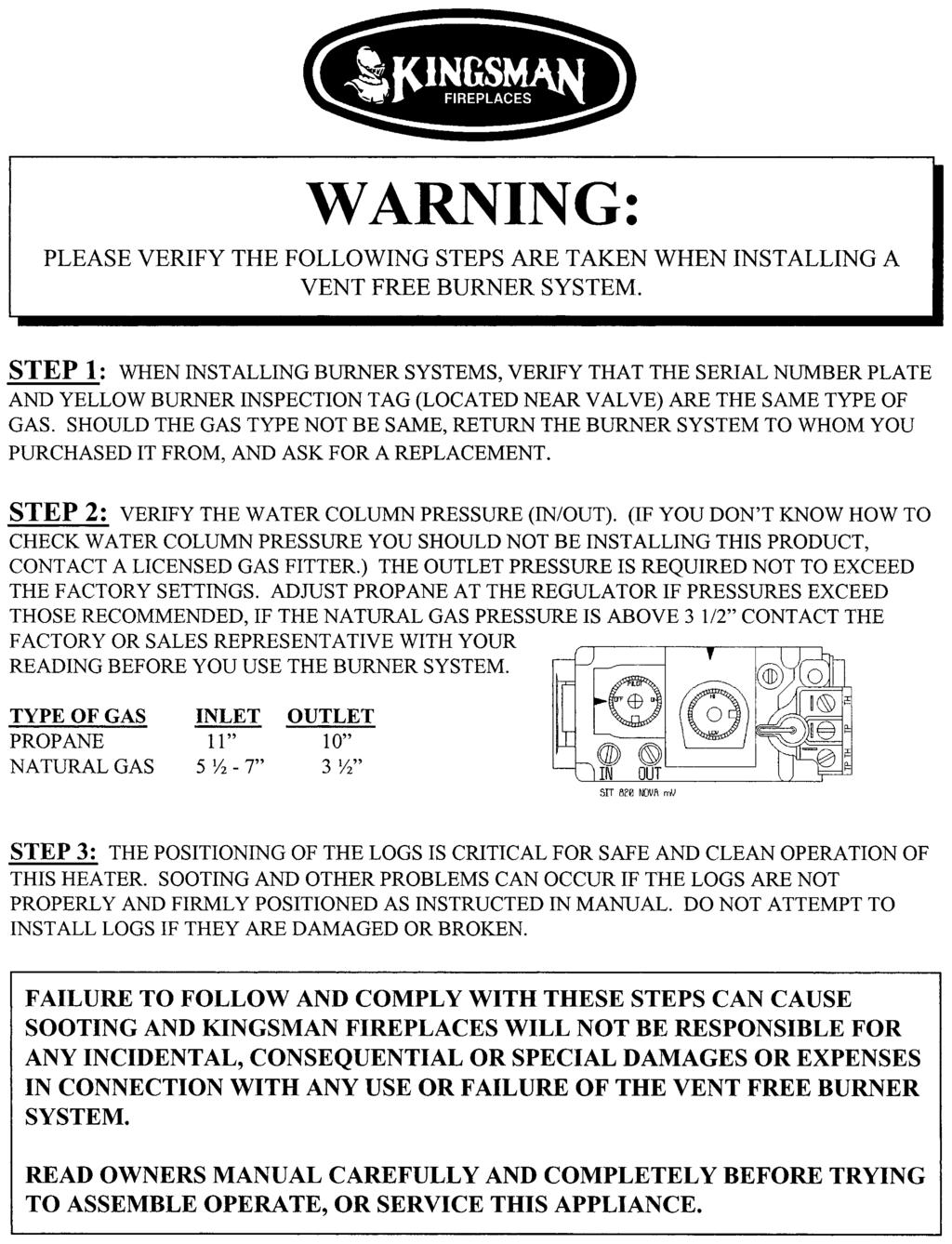
1 Owner s Operation and Installation Manual INSTALLER: Leave this manual with the appliance. CONSUMER: Retain this manual for future reference. Models ZVFCV39, ZVFCV42, ZVFCV47 Certified to: ANSI Z Listed Certified for USA Ventless Firebox Enclosures For Gas-Fired Unvented Decorative Room Heaters -WARNING- Carefully review the instructions supplied with the decorative type unvented room heater for the minimum fireplace size requirement. DO NOT INSTALL AN APPLIANCE IN THIS FIREBOX UNLESS THIS FIREBOX MEETS THE MINIMUM DIMENSIONS REQUIRED FOR THE INSTALLATION. This appliance must be installed by a licensed plumber or gas fitter in the Commonwealth of Massachusetts and meet the requirements of 527 CMR 30 and 248 CMR. -WARNING- This Firebox is to be used only with certain vent-free gas log heaters (refer to table). Do not burn wood or other materials in this firebox. -WARNING- WARNING: If the information in this manual is not followed exactly, a fire or explosion may result causing property damage, personal injury or loss of life. Do not store or use gasoline or other flammable vapors and liquids in the vicinity of this or any other appliance. WHAT TO DO IF YOU SMELL GAS Do not try to light any appliance. Do not touch any electrical switch; do not use any phone in your building. Immediately call your gas supplier from a neighbor s phone. Follow the gas supplier s instructions. If you cannot reach your gas supplier, call the fire department. Installation and service must be performed by a qualified installer, service agency, or the gas supplier. -WARNING- This is an unvented gas-fired heater. It uses air (oxygen) from the room in which installed. Provisions for adequate combustion and ventilation must be provided. -WARNING- FOR USE ONLY WITH A LISTED GAS-FIRED UNVENTED DECORATIVE ROOM HEATER NOT TO EXCEED 40,000 BTU/H. DO NOT BUILD A WOOD FIRE. -WARNING- Improper installation, adjustment, alteration, service, or maintenance can cause injury or property damage. Refer to this manual for correct installation and operational procedures. For assistance or additional information consult a qualified installer, service agency, or the gas supplier. -WARNING- If the information in this manual is not followed exactly, a fire or explosion may result causing property damage, personal injury or loss of life Logan Ave., Winnipeg, MB, Canada, Phone: (204) Printed in Canada April 16, 2015 Pant # 39ZVFCV-MAN
2 Table of Contents Table of Contents. 2 Warning: Please Verify The Following Steps Are Taken When Installing A Vent Free Burner System 3 Pre-installation Questions and Answers / Operating Instructions 4 Burner System Options 5 Safety Information and Warnings Universal Firebox Information. 8 Recommendations for Finishing of Clean View Installations. 9 Framing- Nailing Tab Guide 10 Fireplace Framing ZVFCV Fireplace and Framing Dimensions 12 42ZVFCV Fireplace and Framing Dimensions 13 47ZVFCV Fireplace and Framing Dimensions 14 Installation Clearances 39 / 42 / 47 ZVFCV / 42 / 47 ZVFCV Facing Requirements 16 Basic Finishing 1: No Surround Basic Finishing 2: S1 or S1PF Surround 18 Basic Finishing 3: Concrete Board Behind S2PF Surround (3/4 Maximum Total Thickness). 19 Basic Finishing 4: Stone or Brick Around S2PF Surround.. 20 Basic Finishing 5: Tile Border Behind S2PF Surround (3/4 Maximum Total Thickness) ZVFCV Mantel Clearances ZVFCV Mantel Clearances ZVFCV Mantel Clearances. 24 Air For Combustion And Ventilation ZVFCV 39 / 42 / 47 Z46FK Optional Fan Kit Installation 29 Split Receptacle- Switch Control Outside of Fireplace ULK2 Universal Light Kit -Optional Accent Lighting Kit- ZVFCV39 / 42 / Brick Liner Installation.. 32 Gas Line Installation Installing Burner Systems 35 Installing Log Grate.. 36 Log Placement for LOGF18 (GLVF24) Log Placement for LOGF24 (GLVF24) Log Placement for LOGF30 (GLVF24) Millivolt System, Lighting, and Burner Control. 44 Hood Installation / Pull Screen Removal.. 45 S1 / S1PF / S2PF Surround Installation 46 Troubleshooting ZVFCV39 Parts List.. 49 ZVFCV42 Parts List.. 50 ZVFCV47 Parts List.. 51 Lifetime Limited Warranty 52 2
3 3
4 Pre-installation Questions and Answers About curing of the paint Your stove or fireplace has been painted with the highest quality silicone stove paint. This paint dries quickly in minutes when first applied at the factory. However, due to the high temperature silicone components, the paint will cure when heat is applied to the appliance as it is first used. The following information applies to the curing process to get the paint fully hard and durable. Fire the appliance four successive times for 10 minutes each firing and a 5 minute cool down between each. Be aware during log and firebox paint curing that a white deposit may be developing on the inside of the glass doors. It is important to remove this white deposit from the glass doors using a fireplace glass cleaner. Babies, small children, pregnant women and pets should leave the area during the cure phase. Ventilate well, open doors and windows. Do not touch during curing. Why does my fireplace or stove give off odour? It is normal for your fireplace to give off some odour. This is due to the curing of the paint, adhesives, silicones and any undetected oil from the manufacturing process as well as the finishing materials used with the installations (e.g. marble, tile and the adhesives used to adhere this product to the walls can react with heat and cause odours). It is recommended that you burn your gas fireplace or stove for a minimum of four hours at a time with the fan off (if a fan is present) after the curing of the paint has been completed. These odours can last upward to 40 hours of burn time; keep burning at a minimum of four hours per use until odours dissipate. Noise coming from the fireplace? Noise is caused by the expansion and contraction of metal as the appliance heats up and cools down. This is normal and is similar to the sounds produced by a furnace or heating duct. This noise does not affect the operation or longevity of your fireplace. Operating Instructions 1. Be sure to read and understand all the instructions in this manual before operation of appliance. 2. Ensure all wiring is correct and properly enclosed to prevent possible shock. 3. Check for gas leaks. 4. Make sure the glass door is properly installed before operation. Never operate the appliance with the glass door removed. 5. Make sure venting and termination cap are installed and unobstructed. 6. If brick or porcelain liners are used, ensure they are installed. 7. Verify that the pilot can be seen when lighting the appliance. If not, the log or rock placement is incorrect. 8. If the unit is turned off, you must wait a minimum of 60 seconds before re-lighting it. 4
5 See chart below for required burner system: Burner System Options This appliance is equipped for (Natural or Propane) Gas. Field conversion is not permitted. 39ZVFCV, 42ZVFCV, and 47ZVFCV are approved as Universal Vent Free Boxes. GLVF24 Log Grate Burner System Controls are located underneath log grate inside firebox. Burner Model Valve Type Fuel Type BTU - Input Min/Max Inlet GLVF24MVN Millivolt Natural Gas GLVF24MVP Millivolt Liquid Propane Manifold Pressure Orifice Size Primary Air 25,500 38, / ,000 38,000 11/ Full Open The GL series of gas log sets can be used in ZVFCV39U, ZVFCV42U and ZVFCV47 Universal Fireboxes Fibre Log Set Required for burners above LOGF18 Fibre Log Set 18 (ZVFCV39 / ZVFCV42 / ZVFCV47) LOGF24 Fibre Log Set 24 (ZVFCV39 / ZVFCV42 / ZVFCV47) LOGF30 Fibre Log Set 30 (ZVFCV47 Only) 5
6 SAFETY INFORMATION WARNINGS Important: Read this owner s manual carefully and completely before trying to assemble, operate, or service this firebox. Improper use of this firebox can cause serious injury or death from burns, fire, explosion, electrical shock, and carbon monoxide poisoning. WARNINGS DANGER CARBON MONOXIDE POISONING MAY LEAD TO DEATH! Early signs of carbon monoxide poisoning resemble the flu, with headaches, dizziness, and / or nausea. If you have these signs, the heater may not be working properly. Get fresh air at once! Turn off gas appliance. Have appliance serviced. Some people (such as pregnant women, persons with heart or lung disease, persons with anemia and those at high altitudes) are more affected by carbon monoxide than others. Make certain you read and understand all warnings. This appliance is equipped for (Natural or Propane) Gas. Field conversion is not permitted. Warning: Failure to position parts in accordance with these diagrams or failure to use only part specifically approved with this heater may result in property damages or personal injury. 1. Use correct gas type for your appliance. Do not convert from one gas type to another. 2. If this appliance is for use with Propane gas, do not place propane supply tank(s) inside any structure. Locate propane supply tank(s) outdoors. 3. If you smell gas: Shut off gas supply. Do not try to light any appliance. Do not touch any electrical switch; do not use any phone in your building. Immediately call your gas supplier from a neighbor s phone. Follow the gas supplier s instructions. If you cannot reach your gas supplier, call the fire department. 4. Do not use this appliance for burning trash or cooking. Never place matches, paper, garbage, or any other material on top of logs or logs into flame. 5. Warning: Always operate appliance with front fireplace screens closed. 6. Make sure any safety screen or guard removed for servicing is in place before running appliance. 7. Never run appliance in a small, closed room. Open the door into next room to help ventilate. 8. If appliance shuts off, do not relight until you provide fresh outside air. If appliance keeps shutting off, have it serviced. NOTE: It is recommended that a Carbon Monoxide (CO) Detector be installed in or near bedrooms and on all levels of your home. Place a detector about 15 feet (4.5 meters) outside the room that houses your gas appliance. 9. Do not run appliance: where flammable liquids or vapors are used or stored. under dusty conditions. 10. Surface of appliance becomes very hot when operating. Keep children and adults away from hot surface. Appliance will remain hot for some time after shutdown. Allow surface to cool before touching. 11. Do not use this appliance if any part has been submerged under water. Immediately call a qualified technician to inspect the appliance and to replace any part of the control system and gas control which has been under water. 12. The installation must conform with local codes or, in the absence of local codes, with the National Fuel Gas Code, ANSI Z Never install the appliance: in a bedroom, bathroom, mobile home, or recreational vehicle. where curtains, furniture, clothing, or other flammable objects are less than forty-two inches (42 ) from the front of the appliance. in high traffic areas. in windy or drafty areas. 14. Disconnect the appliance and its individual shut off valve from the gas supply piping system during any pressure testing of that system at test pressures in excess of 1/2 psig, (3.5kPa). 15. Isolate the appliance from the gas supply piping system by closing its individual manual shut off valve during any pressure testing of the the gas supply piping system at test pressure equal or less than 1/2 psig. 16. Do not use any type of after-market blower that fits inside the fireplace. Drafts created by these type of blowers may cause sooting. 6 6
7 SAFETY INFORMATION 17. Turn off appliance and let cool before servicing. Only a qualified service person should install, service and repair appliance. 18. Inspect the appliance before use and at least annually by a professional service person. Frequent cleaning may be required due to excessive lint from carpeting, bedding material, etc. It is important that control compartment, burner and circulating air passage of the appliance be kept open. 19. When operated for the first time, there will be some smell from the appliance. This will diminish and disappear after a few hours of operation. 20. Warning: Do not allow fans to blow directly into the fireplace. Avoid any drafts that alter flame patterns. 21. Warning: Do not use a blower insert, heat exchanger insert or other accessory not approved for use with this heater. WARNINGS Cont. 22. The firebox canopy must not be replaced with a canopy which may be provided with the decorative type UNVENTED room heater. 23. Warning: Do not operate ceiling fans in same room as the vent free appliance. 24. Must be installed by a licensed gasfitter in the Commonwealth of Massachusetts. Complies to code 527CMR. 25. Unvented gas fired appliances may be used only for supplemental heat and/or decorative purposes and under no circumstances shall they provide a primary heat source. LOCAL CODES Install and use fireplace with care. Follow all local codes. In the absence of local codes, use the latest edition of The National Fuel Gas Code ANSI Z223.1, also known as NFPA 54*. Firebox must be electrically grounded in accordance with the National Electrical Code, ANSI/NFPA 70 (latest edition). *Available from: American National Standards Institute, Inc. National Fire Protection Association, Inc Broadway BatterymarchPark New York, NY Quincy, MA FOR YOUR SAFETY READ BEFORE LIGHTING WARNING If you do not follow these instructions exactly, a fire or explosion may result causing property damage, personal injury or loss of life. A. This appliance has a pilot which must be lighted by hand. When lighting the pilot, follow these instructions exactly. B. Before lighting, smell all around the appliance area for gas. Be sure to smell next to the floor because some gas is heavier than air and will settle on the floor. What to do if you smell gas Do not try to light any appliance. Do not touch any electric switch; do not use any phone in your building. Immediately call your gas supplier from a neighbor s phone. Follow the gas supplier s instructions. If you cannot reach your gas supplier, call the fire department. C. Use only your hand to push in or turn the gas control knob. Never use tools. If the knob will not push in or turn by hand, don t try to repair it, call a qualified service technician or gas supplier. Force or attempted repair may result in a fire or explosion. D. Do not use this appliance if any part has been under water. Immediately call a qualified service technician to inspect the appliance and to replace any part of the control system and any gas control which has been under water. 7
8 Universal Firebox The ZVFCV39, ZVFCV42, and ZVFCV47 are approved as Zero Clearance Universal Fireboxes. When installing another manufacturer s log and burner system, follow the manufacturer s assembly instructions. For Framing, refer to appropriate Framing Specifications section in this manual. Follow all Clearances to Combustibles in this manual. When using the optional blower kit (Z46FK) the Thermodisc can be discarded. The two leads from the blower must be attached directly to the variable speed switch. See Fan Installation section for wiring. The fireplace hood is packaged on top of the firebox from the factory. It must be installed on the firebox before operation of the appliance. The firebox hood must not be modified or replaced with a hood which may be provided with the decorative type unvented room heater. USE ONLY KINGSMAN DECORATIVE COMPONENT AND REPLACEMENT PARTS. Model Firebox Height Firebox Width Front Firebox Width Back Firebox Depth Firebox Max BTU ZVFCV ,000 ZVFCV ,000 ZVFCV ,000 Hood Pull Screen Access Cover Pull Screen 8
9 Recommendations for Finishing of Clean View Installations When finishing the wall around the fireplace, it is critical that the wall covering be fastened properly. It is acceptable to pre-drill holes and use self-tapping screws which may be used to fasten a backer for tile, marble, etc. Screws being installed through non-combustible board should be self-tapping type with a maximum length of 2 inches. Wall covering fasteners, such as screws or nails, are not permitted in some locations. Do not drill or install longer screws which may penetrate into the lower panel area as this may damage internal components. Only non-combustible materials may be used over the face of the appliance. We recommend that DUROCK (non-combustible material) be tied in to the entire perimeter of framing for durability. Finishing Recommendations (Obtained from professional construction contractors and finishers): Frame unit with metal studs (minimum 20 gauge). Minimum of 1/2 DUROCK cement board (this non-combustible panel is ULC listed as a wall shield/floor protector) and fasten to the entire perimeter framing. Use fiberglass (mesh) tape for all joints in area of the fireplace. Use Yellow joint mud (contains high amounts of glue) two coats, finishing with one coat of green topping mud, sand and prep for painting. If not using a surround, a metal L Trim may be used to finish perimeter of DUROCK. Refer to the following website for more information on using DUROCK Cement Board: OTHER NOTES: -A full single sheet of non-combustible board (no joints) above the unit is recommended if possible. -It is preferred to attach the non-combustible board to framing only and not directly to the unit to allow for expansion and contraction during normal operation. -Lighter colored painted surfaces may discolor due to heat exposure. 9
![ZCV39 / ZCV42 Framing- Nailing Tab Guide [Qty]2 Nailing Tabs are located on each side of the front frame.](/docs-images/90/101619895/images/10-2.jpg "1/2 Drywall Flush with Face of Fireplace Fireplace and Combustible Wall to be covered with a surround or Non-Combustible Materials (e.g. Stone around Fireplace).")
10 ZCV39 / ZCV42 Framing- Nailing Tab Guide [Qty]2 Nailing Tabs are located on each side of the front frame. 1/2 Drywall Flush with Face of Fireplace Fireplace and Combustible Wall to be covered with a surround or Non-Combustible Materials (e.g. Stone around Fireplace). These Nailing Tabs can be used in two ways: Framing Flush with Face of Fireplace -Fireplace to be covered with Non-Combustibles (e.g. Concrete Board) for Flat Wall appearance. Nailing Tab Nailing Tab Framing Stud Framing Stud Drywall Drywall Non-Combustible Material (eg. Stone) Non-Combustible Material (eg. Concrete Board) Nailing Tab Framing Mount Nailing Tabs Must Be Rotated 180 And Folded Back Onto Framing Stud. Framing Stud Framing Stud Nailing Tab Nailing Tab Flush Surface 10
11 39 / 42 / 47 ZVFCV Fireplace Framing Fireplace Framing Built-in installation of this firebox involves installing firebox into a framed-in enclosure. Optional surrounds are available. Some Surrounds (i.e. S1, S1PF) will extend past sides of firebox. This will cover the rough edges of the wall opening. If installing a mantel above the firebox, you must follow the clearances shown in the Mantel Clearances section. Follow the instructions below to install the firebox. 1. Decide how your fireplace will be finished (i.e. with surround or tile, etc.) before framing fireplace. Refer to Nailing Tab Guide and Fireplace and Framing Dimensions sections. The firebox framing should be constructed of 2 x 4 wood or metal. The table below lists the rough opening dimensions for each model. Rough Opening Dimensions Width Height Depth* 39ZVFCV 39-1/2 37-5/ /16 42ZVFCV 42-1/2 40-3/8 20-5/16 47ZVFCV 48-1/2 45-7/ /8 *Depth may vary depending upon how fireplace will be finished. Refer to Nailing Tab Guide section. 2. Install gas piping to firebox location. See Installing Gas Line section and Connecting to Gas Supply in log set owner s manual. IMPORTANT: If installing blower accessory see Fan Installation section. 3. Carefully insert firebox into rough opening. 4. Attach firebox to wall studs using nails or wood screws through holes in nailing flange. 5. If using optional surround, install surround after final finishing and/or painting of wall. See appropriate Surround Installation instructions. 6. Install and properly test gas log heater. Follow installation instructions included with the vent-free gas log heater that is being installed. CAUTION If appliance is installed directly on carpeting or other combustible material other than wood flooring, a metal or wood panel extending the full width and depth of the appliance must be used. Carpet may extend 1 inch above the floor of the appliance. CAUTION Log heaters installed in this firebox create warm air currents. These currents move heat to wall surfaces next to firebox. Installing firebox next to vinyl or cloth wall coverings or operating firebox where impurities in the air (such as tobacco smoke) exist, may discolor walls. WARNING Do not allow any combustible materials to overlap the firebox front facing. WARNING Non-combustible materials such as brick, tile, etc. may overlap the front facing, but should never cover any necessary openings such as the access panel area. WARNING Use only non-combustible mortar or adhesives when overlapping the front facing with non-combustible facing material. WARNING Never modify or cover the front opening of the firebox. WARNING Do NOT fill space around firebox with insulation or other materials. WARNING Do not notch framing or alter standoffs. 11
. Refer to Nailing Tab Guide section also.")
12 39ZVFCV Fireplace and Framing Dimensions Determine whether face of fireplace will be: Flush with finished wall (e.g., for surround, cultured stone or other non-combustible covering). Flush with framing (to be covered with concrete board for a Flat Wall appearance). Refer to Nailing Tab Guide section also. 83 Minimum Clearance to Ceiling 83 Minimum Clearance to Ceiling 41-1/8 Minimum Enclosure 41-1/8 Minimum Enclosure 12
. Refer to Nailing Tab Guide section also.")
13 42ZVFCV Fireplace and Framing Dimensions Determine whether face of fireplace will be: Flush with finished wall (e.g., for surround, cultured stone or other non-combustible covering). Flush with framing (to be covered with concrete board for a Flat Wall appearance). Refer to Nailing Tab Guide section also. 83 Minimum Clearance to Ceiling 83 Minimum Clearance to Ceiling 44-1/4 Minimum Enclosure 44-1/4 Minimum Enclosure 13
. Refer to Nailing Tab Guide section also.")
14 47ZVFCV Fireplace and Framing Dimensions Determine whether face of fireplace will be: Flush with finished wall (e.g., for surround, cultured stone or other non-combustible covering). Flush with framing (to be covered with concrete board for a Flat Wall appearance). Refer to Nailing Tab Guide section also. 83 Minimum Clearance to Ceiling 83 Minimum Clearance to Ceiling 49-5/16 Minimum Enclosure 49-5/16 Minimum Enclosure 14
15 Installation Clearances 39 / 42 / 47 ZVFCV Carefully follow the instructions below. This will ensure safe installation. NOTICE A qualified service person must install firebox. Follow all local codes. IMPORTANT: Vent-free gas log heaters add moisture to the air. Although this is beneficial, installing firebox in rooms without enough ventilation air may cause mildew to form from too much moisture. See Air for Combustion and Ventilation section in this manual. WARNING Never install the firebox: in a bedroom or bathroom in a recreational vehicle where curtains, furniture, clothing, or other flammable objects are less than 36 inches from the front, top, or sides of the firebox in high traffic areas in windy or drafty areas IMPORTANT: Make sure the firebox is level. If firebox is not level, log set will not work properly. Clearance To Combustibles 39ZVFCV 42ZVFCV 47ZVFCV A Front of Fireplace B Back (From Stand-offs) C Side (From Stand-offs) D Floor* E Bottom of Fireplace to Ceiling F Top (From Stand-offs) G Top of Fireplace to Minimum Enclosure *Note: If appliance is installed directly on carpeting or other combustible material other than wood flooring, a metal or wood panel extending the full width and depth of the appliance must be used. Carpet may extend 1 inch above the floor of the appliance. WARNING Ensure the minimum clearances are maintained. Left and right clearances are determined when facing the front of the heater. WARNING Maintain the minimum clearances. If you can, provide greater clearances from floor, ceiling, and adjoining wall. 15
 Note: Do not drive excessively long screws into the face of the unit as internal parts may be damaged.")
 16")
16 39 / 42 / 47 ZVFCV Facing Requirements Required Non-Combustible Areas If materials will be covering the face of the fireplace they must be non-combustible (i.e. brick stone, tile, concrete board). See Basic Finishing sections 1-5 also. FRONT VIEW ANY MATERIALS COVERING FACE OF FIREPLACE MUST BE NON COMBUSTIBLE. This area can have a combustible surface (i.e. drywall) Note: Do not drive excessively long screws into the face of the unit as internal parts may be damaged. SIDE VIEW -Combustible Mantel Line- Refer to Mantel Clearances section for more detailed information. Any materials covering the face of the fireplace MUST be non-combustible (i.e. brick stone, tile, concrete board). Minimum Height for Top Enclosure. Increase dimension as required. This area can have a combustible surface (i.e. hearth) 16

17 ZVFCV 39 / 42 / 47 Basic Finishing 1: No Surround Step One: Frame Fireplace with nailing tabs oriented as shown. Step Two: Use Drywall to finish face of wall. NOTE: Drywall will be flush with fireplace face. Drywall Nailing Tab Fireplace Frame Fireplace Opening Step 3: A brick, tile, or other non-combustible border may be applied over fireplace face to conceal border. Optional: A Tile Lip Kit is Available. Part No. ZCV-TLK Tile Drywall Fireplace Frame ZCV-TLK Fireplace Frame Drywall Fireplace Opening Fireplace Opening 17

18 ZVFCV 39 / 42 / 47 Basic Finishing 2: S1 or S1PF (ZVFCV39 / 42 Only) Surround Step One: Frame Fireplace with nailing tabs oriented as shown. Step Two: Use Drywall to finish face of wall. NOTE: Drywall will be flush with fireplace face. Drywall Nailing Tab Fireplace Frame Fireplace Opening Step 3: Once wall is completely finished, Surround may be installed. Surround will conceal edges of fireplace. Surround Drywall Note: If installing tile, brick, or other material around the perimeter of the surround: You MUST Leave 4 of the face exposed around the fireplace opening on the Sides, 4 at the Bottom for the S1PF, and S1 must be clear at Bottom. 4-1/16 must be exposed on the top. This is to install and remove the Surround. A Tile Lip Kit is Available. Part No. ZCV-TLK Fireplace Opening ZCV-TLK Here Drywall 4-1/16 MIN Fireplace Frame Fireplace Opening 4 MIN 18
. Step Two: Use Concrete Board to cover fireplace face. NOTE: Optional ZCV-TLK Tile Kit is available.")


19 ZVFCV 39 / 42 Basic Finishing 3 Concrete Board Behind S2PF Surround (3/4 Maximum Total Thickness) Step One: Frame Fireplace with nailing tabs oriented as shown (Flush with face of fireplace). Step Two: Use Concrete Board to cover fireplace face. NOTE: Optional ZCV-TLK Tile Kit is available. Maintain clearances shown. Nailing Tab Optional ZCV-TLK Tile Kit 1-3/16 MIN Fireplace Opening 1 MIN Step 3: Concrete Board with optional Tile Lip shown below. Once wall is completely finished, Surround may be installed. IMPORTANT NOTE!: If installing tile, brick, or other non-combustible material around the perimeter of the S2PF2 Surround, Maintain clearances shown below. Optional ZCV-TLK Tile Kit is available. Also See Basic Finishing 4. Concrete Board Optional ZCV-TLK Tile Kit 1-3/16 MIN Concrete Board 1-15/16 MIN Concrete Board S2PF SURROUND Fireplace Opening 1 MIN Fireplace Opening 1-3/4 MIN Concrete Board 19
20 ZVFCV 39 / 42 Basic Finishing 4: Stone or Brick Around S2PF Surround Step One: Frame Fireplace with nailing tabs oriented as shown. Step Two: Use Drywall to finish face of wall. NOTE: Drywall will be flush with fireplace face. Drywall Nailing Tab Fireplace Frame Fireplace Opening Step Three: When installing tile, brick, or other non-combustible material around the perimeter of the S2PF2 Surround, Maintain clearances shown below. You MUST Leave 1-3/4 of the face exposed around the fireplace opening on the Bottom and Sides, and 1-15/16 exposed on the top. This is to install and remove the surround. Optional: A Tile Lip Kit is Available. Part No. ZCV-TLK STONE, BRICK, ETC. Concrete Board S2PF SURROUND S2PF SURROUND 1-15/16 MIN Fireplace Opening 1-3/4 MIN Concrete Board Fireplace Opening 20
21 ZVFCV 39 / 42 Basic Finishing 5: Tile Border Behind S2PF Surround (3/4 Maximum Total Thickness) Step One: Frame Fireplace with nailing tabs oriented as shown. Step Two: Use Drywall to finish face of wall. NOTE: Drywall will be flush with fireplace face. Drywall Nailing Tab Fireplace Frame Fireplace Opening Step 3: A tile border may be applied over fireplace face. Maintain clearances below. Optional: A Tile Lip Kit is Available. Part No. ZCV-TLK Tile Tile S2PF Surround 1-3/16 MIN Drywall Tile Fireplace Opening 1 MIN Fireplace Opening 21
22 39ZVFCV Before installing any mantels it is important to determine the combustibility of its material(s). There are two types of mantels to consider: Combustible and Non-Combustible. A Combustible Mantel is one that consists of material(s) that may discolor, combust, or lose its integrity in the presence of heat. These types of mantels must strictly conform to the dimensional requirements shown. Conversely, a Non-Combustible Mantel is one that is constructed with material(s) that will not combust. Check your local codes and regulations to determine whether your mantel is combustible or Non-Combustible. The advantage to Non-Combustible Mantels is that it may extend right up to the tile lip of the fireplace. Combustible mantels must adhere to the dimensional restrictions shown. -Combustible Objects on Non- Combustible Mantel Warning- Combustible objects must not be placed on a Non-combustible Mantel unless the mantel meets the dimensional requirements for a Combustible Mantel. Determine whether your mantel conforms to the requirements of a Combustible Mantel. Mantel Clearances Mantel Dimensions are from front face or Non-Combustible Facing Materials covering fireplace. Mantel Leg Clearances Top View Adjacent Wall Adjacent Wall 22
23 42ZVFCV Before installing any mantels it is important to determine the combustibility of its material(s). There are two types of mantels to consider: Combustible and Non-Combustible. A Combustible Mantel is one that consists of material(s) that may discolor, combust, or lose its integrity in the presence of heat. These types of mantels must strictly conform to the dimensional requirements shown. Conversely, a Non-Combustible Mantel is one that is constructed with material(s) that will not combust. Check your local codes and regulations to determine whether your mantel is combustible or Non-Combustible. The advantage to Non-Combustible Mantels is that it may extend right up to the tile lip of the fireplace. Combustible mantels must adhere to the dimensional restrictions shown. -Combustible Objects on Non- Combustible Mantel Warning- Combustible objects must not be placed on a Non-combustible Mantel unless the mantel meets the dimensional requirements for a Combustible Mantel. Determine whether your mantel conforms to the requirements of a Combustible Mantel. Mantel Clearances Mantel Dimensions are from front face or Non-Combustible Facing Materials covering fireplace. Mantel Leg Clearances Top View Adjacent Wall Adjacent Wall 23
24 47ZVFCV Before installing any mantels it is important to determine the combustibility of its material(s). There are two types of mantels to consider: Combustible and Non-Combustible. A Combustible Mantel is one that consists of material(s) that may discolor, combust, or lose its integrity in the presence of heat. These types of mantels must strictly conform to the dimensional requirements shown. Conversely, a Non-Combustible Mantel is one that is constructed with material(s) that will not combust. Check your local codes and regulations to determine whether your mantel is combustible or Non-Combustible. The advantage to Non-Combustible Mantels is that it may extend right up to the tile lip of the fireplace. Combustible mantels must adhere to the dimensional restrictions shown. -Combustible Objects on Non- Combustible Mantel Warning- Combustible objects must not be placed on a Non-combustible Mantel unless the mantel meets the dimensional requirements for a Combustible Mantel. Determine whether your mantel conforms to the requirements of a Combustible Mantel. Mantel Clearances Mantel Dimensions are from front face or Non-Combustible Facing Materials covering fireplace. Mantel Leg Clearances Top View Adjacent Wall Adjacent Wall 24
25 AIR FOR COMBUSTION AND VENTILATION Today s homes are built more energy efficient than ever. New materials, increased insulation, and new construction methods help reduce heat loss in homes. Home owners weather strip and caulk around windows and doors to keep the cold air out and the warm air in. During heating months, home owners want their homes as airtight as possible. WARNING This firebox shall not be installed in a confined space unless provisions are provided for adequate combustion and ventilation air. Read the following instructions to insure proper fresh air for this and other fuel-burning appliances in your home. While it is good to make your home energy efficient, your home needs to breathe. Fresh air must enter your home. All fuel-burning appliances need fresh air for proper combustion and ventilation. Exhaust fans, fireboxes, clothes dryers, and fuel burning appliances draw air from the house to operate. You must provide adequate fresh air for these appliances. This will insure proper venting of vented fuel-burning appliances. PROVIDING ADEQUATE VENTILATION The following are excerpts from National Fuel Gas Code. NFPA 54/ANSI Z223.1, Section 5.3, Air for Combustion and Ventilation: All spaces in homes fall into one of the three following ventilation classifications: 1. Unusually Tight Construction, 2. Unconfined Space, 3. Confined Space. The information on pages 14 through 16 will help you classify your space and provide adequate ventilation. Unusually Tight Construction The air that leaks around doors and windows may provide enough fresh air for combustion and ventilation. However, in building of usually tight construction, you must provide additional fresh air. Unusually tight construction is defined as construction where: a. walls and ceilings exposed to the outside atmosphere have a continuous water vapor retarder with a rating of one perm (6 x per pasec-m2) or less with openings gasketed or sealed and b. weather stripping has been added on openable windows and doors and c. caulking or sealants are applied to areas such as joints around window and door frames, between sole plates and floors, between wall-ceiling joints, between wall panels, at penetrations for plumbing, electrical, and gas lines, and at other openings. If your home meets all of the three criteria above, you must provide additional fresh air. See Ventilation Air From Outdoors. Confined and Unconfined Space The National Fuel Gas Code (ANSI Z223.1, 1992 Section 5.3) defines a confined space as a space whose volume is less than 50 cubic feet per 1,000 btu per hour (4.8 m3 per kw) of the aggregate input rating of all appliances installed in that space. Rooms communicating directly with the space in which the appliances are installed*, through openings not furnished with doors, are considered a part of the unconfined space. *Adjoining rooms are communicating only if there are doorless passageways or ventilation grills between them. DETERMINING AIR FLOW FOR FIREBOX LOCATION Determining if You Have a Confined or Unconfined Space Use the work sheet on the next page to determine if you have a confined or unconfined space. Space: Includes the room in which you will install firebox plus any adjoining rooms with doorless passageways or ventilation grills between the rooms. 25
26 AIR FOR COMBUSTION AND VENTILATION Cont. 1. Determine the volume of the space (length x width x height). Length x Width x Height = cu. ft. (volume of space) Example: Space size 22ft. (length) x 18 ft. (width) x 8 ft. (ceiling height) = 3168 cu. ft. (volume of space) If additional ventilation to adjoining room is supplied with grills or openings, add the volume of these rooms to the total volume of the space. 2. Divide the space volume by 50 cubic feet to determine the maximum Btu/Hr the space can support. (volume of space) 50 cu. ft. = 63.3 or 63,300 (maximum Btu/Hr the space can support) 3. Add the Btu/Hr of all fuel burning appliances in the space. Vent-free firebox Gas water heater* Gas furnace Vented gas heater Gas firebox logs Other gas appliances* Total Btu/Hr Btu/Hr Btu/Hr Btu/Hr Btu/Hr + Btu/Hr = Btu/Hr Example: Gas water heater 40,000 Btu/Hr Vent-free firebox with log heater + 39,000 Btu/Hr Total = 79,000Btu/Hr * Do not include direct-vent gas appliances. Direct-vent draws combustion air from the outdoors and vents to the outdoors. 4. Compare the maximum Btu/Hr the space can support with the actual amount of Btu/Hr used. Btu/Hr (maximum the space can support) Btu/Hr (actual amount of Btu/Hr used) Example: 63,300 Btu/Hr (maximum the space can support) 79,000 Btu/Hr (actual amount of Btu/Hr used) The space in the above example is a confined space because the actual Btu/Hr used is more than the maximum Btu/Hr the space can support. You must provide additional fresh air. Your options are a follows: A. Rework work sheet, adding the space of an adjoining room. If the extra space provides and unconfined space, remove door to adjoining room or add ventilation grills between rooms, See Ventilation Air from Inside Building. B. Vent room directly to the outdoors. See ventilation Air from Outdoors. C. Install a lower Btu/Hr firebox, if lower Btu/Hr size makes room unconfined. If the actual Btu/Hr used is less than the maximum Btu/Hr the space can support, the space is an unconfined fined space. You will need no additional fresh air ventilation. WARNING If the area in which the firebox and gas log heater may be operated is smaller than that defined as an unconfined space, provide adequate combustion and ventilation air by one of the methods described in the National Fuel Gas Code, ANSI Z223.1, 1992, Section
27 AIR FOR COMBUSTION AND VENTILATION Cont. VENTILATION AIR FROM INSIDE BUILDING This fresh air would come from an adjoining unconfined space. When ventilating to an adjoining unconfined space, you must provide two permanent openings: one within 12 of the ceiling and one within 12 of the floor on the wall connecting the two spaces. You can also remove door into adjoining room. Follow the National Fuel Gas Code NFPA 54/ANSI Z223.1, Section 5.3, Air for Combustion and Ventilation for required size of ventilation grills or ducts. WARNING Rework worksheet, adding the space of the adjoining unconfined space. The combined spaces must have enough fresh air to supply all appliances in both spaces. FIGURE 5 - Ventilation Air from Inside Building 27
28 AIR FOR COMBUSTION AND VENTILATION Cont. Ventilation Air From Outdoors Provide extra fresh air by using ventilation grills or ducts. You must provide two permanent openings: one within 12 of the ceiling and one within 12 of the floor. Connect these items directly to the outdoors or spaces open to the outdoors. These spaces include attics and crawl spaces. IMPORTANT: Do not provide openings for inlet or outlet air into attic if attic has a thermostat-controlled power vent. Heated air entering the attic will activate the power vent. FIGURE 6 - Ventilation Air from Outdoors 28
 plug for your")


29 ZVFCV 39 / 42 / 47 NOTE: Thermodisc will NOT be used. See diagram below. WARNING -Electrical Grounding Instructions- This appliance is equipped with a three prong (grounding) plug for your protection against shock hazard and should be plugged directly into a properly grounded three-prong receptacle. Do not cut or remove the grounding prong from this. Z46FK Optional Fan Kit Installation WARNING Before Servicing 1. Ensure all power supply is shut off. 2. Label all wires prior to disconnecting when servicing control. Wiring errors can cause improper and dangerous operation. 3. For fan servicing: Vacuum and clean lint/dirt build-up on the fan blades and motor. 1. Remove Fan Access Cover from back of firebox. 2. Insert Fan Assembly through opening. 3. Set Fan Housing onto Mount Tabs. 4. Route wires under Firebox to right side of Fireplace. Thermodisc is NOT used Connect leads from Blower directly to leads from Fan Speed Control. Use extra male connector supplied in Z46FK Fan Kit. 29

 plug for your protection against shock hazard and should be plugged directly into a properly grounded")
30 Split Receptacle- Switch Control Outside of Fireplace If you wish to have a control switch outside of the fireplace for one side of the receptacle and you require a constant source of AC power inside the unit for another accessory such as lights or an IPI valve system, follow one of the procedures below. WARNING WARNING WARNING A qualified electrician must connect electrical wiring to junction outlet for built-in installation. Follow all codes. Electrical Grounding Instructions This appliance is equipped with a three pronged (grounding) plug for your protection against shock hazard and should be plugged directly into a properly grounded three-prong receptacle. Label all wires prior to disconnection when servicing controls. Wiring errors can cause improper and dangerous operation. Verify proper operation and servicing. Caution: Electrical installation to be done by a qualified installer. All wires must be connected and grounded in accordance with CSA Standard C22.1- Canadian Electrical Code part 1 or with the National Electrical Code, ANSI /NFPA 70 (latest edition) and /or in accordance with local codes. Switch Controlled Split Receptacle With Switch At START Of Cable Run Switch Controlled Split Receptacle With Switch At END Of Cable Run 30


![3 prong plug & wire connectors Light Switch & Cover Plate c/w10ft wire c/w [1] Loose Female & [1] Loose](/docs-images/90/101619895/images/31-4.jpg "Male wire connector Lamp Lamp Inside Firebox Bottom of Firebox Connect Switch Here STEP 1: Insert wires")
.")
31 ULK2 Universal Light Kit -Optional Accent Lighting Kit- ZVFCV39 / 42 / 47 Please follow the current ANSI/NFPA 70 National Electrical Code in the USA and CAN/CSA C22.1 Canadian National Electrical Code in Canada. Contents of Kit: [2] 12V Halogen Lamps Lamp Plate with Insulated Studs & wiring 12VAC Transformer with 3 prong plug & wire connectors Light Switch & Cover Plate c/w10ft wire c/w [1] Loose Female & [1] Loose Male wire connector Lamp Lamp Inside Firebox Bottom of Firebox Connect Switch Here STEP 1: Insert wires through access hole in firebox. Fasten cover plate and lamps in place. STEP 2: Connect switch wires between lamp wire and transformer (see drawings). Connect remaining lamp wire to transformer. Transformer can then be plugged in and the housing fastened to the bottom of the fireplace using mount tabs. 31


32 ZCV39RL / ZCV42RL / ZCV47RL Brick Liner Installation for ZVFCV 39 / 42 / 47 WARNING: Failure to position the parts in accordance with these diagrams or failure to use only parts specifically approved with this appliance may result in property damage or personal injury. Step One: Start with a clean, empty firebox. Step Two: Place Back Liner against back wall of firebox. Step Three: Tilt and slide left and right Side Liners into place. Step Four: Fix Side Liners in place using Liner Retainer Clips. Step Five: Installation is complete. 32
33 INSTALLING Gas Line INSTALLING GAS LINE Early signs of carbon monoxide poisoning resemble the flu, with headaches, dizziness, and / or nausea. If you have these signs, the heater may not be working properly. Get fresh air at once! Turn off gas appliance. Have appliance serviced. Some people (such as pregnant women, persons with heart or lung disease, persons with anemia and those at high altitudes) are more affected by carbon monoxide than others. Make certain you read and understand all warnings. Place Burner Base / Grate Assembly in center of firebox and connect flexible gas line to incoming black iron pipe gas line. Do not connect appliance before pressure testing gas piping. Damage to gas valve may result and an unsafe condition may be caused. Prepare incoming black iron gas line with Teflon tape or pipe joint compound (check with local codes about the use of Teflon tape). Compounds used on threaded joints of gas piping shall be resistant to the action of Liquefied Petroleum (LP or Propane) and should be applied lightly to ensure excess sealant does not enter the gas line. Complete your gas installation by connecting incoming gas line to regulator. Secure all joints tightly with wrench but do not over-tighten. If a flexible gas line is used, take care not to kink connector. The burner pressure is controlled by the (cont d. on next page ) DANGER CARBON MONOXIDE POISONING MAY LEAD TO DEATH! WARNING Any changes to this heater or its controls can be dangerous. NOTICE Installation and repair should be done by a qualified service person well trained in the installation of such appliances. You will also need a building permit from your local Building Commissioner before installing this appliance, otherwise your insurance company may not cover this appliance. FIGURE 9, 9a Gas line and manual shutoff valve 33
34 INSTALLING Gas Line Cont. CAUTION Any safety screen or guard removed for servicing an appliance must be replaced prior to operating the heater. NOTICE A qualified gas appliance installer must connect the fireplace to the gas supply. Consult all local codes. CAUTION Use new black pipe only. Internally tinned copper tubing can be used in some areas when permitted by local codes. Only use pipe of 1/2 or greater diameter to allow full gas volume to heater. Excessive pressure loss will occur if the pipe is too small. A manual shutoff valve, union and plugged 1 8 NPT pressure tap pointer must be installed upstream of the heater. A sediment trap must be installed upstream of the heater to prevent moisture and contaminants from passing through the pipe to the heater controls and burners. Failure to do so could prevent the heater from operating reliably. regulator. Check pressure at the pressure test point, which is located on the side of the gas control near the pilot outlet. Make sure that the pressure tap is completely closed after checking gas pressure. The pressure should be checked with the appliance burning and the control set on high. IMPORTANT: Loosen the pipe adapter on the flex tube before installing to the system piping. CHECK GAS TYPE: The gas supply must be the same as stated on the heater s rating plate. If the gas supply is different, Do Not Install the heater. Contact your dealer for the correct model. CAUTION All gas piping and connections must be tested for leaks after installation is completed. To test, turn gas valve on, then apply a soap and water solution to all connections and joints. If bubbles appear, leak can be detected and corrected. Never use an open flame for leak testing. Never operate any appliance if a leak is detected! For the state of Massachusetts a T-handle gas shut-off valve must be used on a gas appliance. This T-handle gas shut-off valve must be listed and approved by the state of Massachusetts. This is in reference to the state of Massachusetts state code CMR

35 Installing Burner Systems Installing Burner Systems into Firebox The Zero Clearance Fireplaces ZVFCV36 / 42 / 47 have the option of being installed with either the GLVF24 Vent Free Burner Systems or other approved vent free burner systems. Warning: Failure to position parts in accordance with these diagrams or failure to use only part specifically approved with this heater may result in property damages or personal injury. Installing GLVF24 Vent Free Burner System with grate: 1. If using optional blower it is recommended to install fan now to make installation easier. Refer to Installation of Optional Fan section. 2. Follow instructions included with GLVF24 Burner System with grate. 3. Connect gas supply to the burner system. Refer to Installing Gas Line section. 4. Proceed to Log Placement. If using another manufacturer s burner system and logs, follow manufacturer s installation instructions. WARNING Failure to keep primary air openings clear, may result in sooting and property damage. WARNING Turn off heater and allow to cool before cleaning. Only a qualified service technician should service and repair appliance. Cleaning and Servicing of Burner / ODS Pilot It is recommended to annually inspect and clean the unit to prevent malfunction and / or sooting. This operation should be performed by your dealer or a qualified technician. Remove log set, handling carefully by holding gently at each end. (Refer to Log Placement) Gloves are recommended to prevent skin irritation from ceramic. Annual Cleaning / Inspection Do not use cleaning fluids to clean logs or any part of the heater. Use a soft bristle brush or a vacuum with brush attachment. Vacuum loose particles and dust from burner ports, valve and blower compartments. Vacuum any accumulation of lint from primary mixing tube. Inspect ODS pilot for operation, accumulation of lint at the air inlet holes. Verify flame pattern and log placement for proper operation. Verify that all ports ignite and cross over smoothly from rear to front burner. CAUTION Never use a wire, needle, or similar object to clean ODS / Pilot. This can damage ODS / Pilot. Air Inlet Holes Flame should touch thermocouple and thermopile 35
36 INSTALLING Log Grate ATTACHING LOG GRATE TO FIREPLACE BASE 1. Position log grate into fireplace and mark screw locations on each side of mounting bracket. 2. Remove grate assembly, drill 2 holes at the marked locations. 3. Attach grate assembly to fireplace base. (Screws not provided.) 4. Connect to gas supply. INSTALLATION OF LOGF24 LOGSET 1. Place main log on locating pins on burner grate bottom. 2. Place crossover log on locating pins on top of rear main log. 3. Position front log flat surface up to main log. WARNING You must secure this heater to fireplace base, or heater will move when you adjust controls. Moving heater may cause a gas leak and may result in property damage or personal injury. WARNING Failure to position the parts in accordance with the diagrams or failure to use only parts specifically approved with this heater may result in property damage or personal injury. ➁ ➃ ➀ ➂ Kingsman Replacement Log Listing Reference Part Number Number Description 1 24F-A Front Main Log A, LOGF F-B Rear Main Log B, LOGF F-C Front Log C, LOGF F-D Crossover Log D, LOGF24 FIGURE 12 Log Placement WARNING The positioning of the logs is critical for the safe and clean operation of this heater. Sooting and other problems can occur if the logs are not properly and firmly positioned in the heater. Never add additional logs or embellishments such as pine cones,vermiculite, volcanic rock or rock wool to the heater
 Locate hole on the underside of Log C. Place log over front burner and locator pin then lower into position (as illustrated). Step (3) Locate hole on the underside of Log D.")
37 LOGF18 PLACEMENT GUIDELINES Rear Log Holder Burner Log Locator pin Log Locator pin Burner Assembly base Step (1) Remove logs from carton and inspect each log. Step (2) Locate hole on the underside of Log C. Place log over front burner and locator pin then lower into position (as illustrated). Step (3) Locate hole on the underside of Log D. Place log over front burner and locator pin then lower into position (as illustrated). Step (4) Using Log B, place flat surface of the log onto burner assembly base. Push log up to Log C & D. 37

38 LOGF18 PLACEMENT GUIDELINES (continued) Step (5) Place log A onto rear log holder and pull up to log C & D. 38
 Remove logs from")
 Place front main log A on log locator pins.")


39 LOGF24 PLACEMENT GUIDELINES Rear Log Holder Burner Log locator pin Burner Assembly base Step (1) Remove logs from carton and inspect each log. Step (2) Place front main log A on log locator pins. Retainer pin Step (3) Position rear main log B onto rear log holder located on rear of firebox. Position locking tabs of rear main log B into locking tabs of front main log A. Step (4) Place crossover log D onto the retainer pins located on the top of rear main log B. 39
 Place Log C onto front burner.")
40 LOGF24 PLACEMENT GUIDELINES (continued) Step (5) Place Log C onto front burner. 40
41 LOGF30 Log Installation 1. Align front hole of log support plate with original log locator pin. 2. Slide log support over pin & using two DT screws, mount plate to burner grate. NOTE: Make sure log support is tight against side of burner grate before fastening. Log Locator Tab Log Support Original Log Locator Pin 41

 Align front hole of 30 inch log support plate with original log locator pin.")

 Place front log by positioning the notches on the underside of the front log")
 Place left front log by positioning the slot (located on the bottom of log)")
42 LOGF30 PLACEMENT GUIDELINES Log locator pin Rear log holder Log Locator tabs 30 inch Log support Grate Bars When using the LOGF30 log, you must attach the 30 inch log supports found in the log set. Step (1) Align front hole of 30 inch log support plate with original log locator pin. Step (2) Slide the 30 inch log support over log locator pin. Using two 6-32 x 5/16 screws, mount plate to burner grate. NOTE: Make sure log support is tight against side of burner grate before fastening. Step (3) Place front log by positioning the notches on the underside of the front log with the grate bars and pull forward. Step (4) Place left front log by positioning the slot (located on the bottom of log) with log retainer tab and lower into position. Step (5) Place right front log by positioning the slot (located on bottom of log) with log retainer tab and lower into position. 42

 Place rear log onto the rear")


43 Step (8) Line up right crossover log with locator pins and lower into position. Complete LOGF30 Logset. Step (6) Place rear log onto the rear log holder and pull up to the left and right front logs. Step (7) Line up left crossover log with locator pins and lower into position. LOGF30 PLACEMENT GUIDELINES (continued) 43
44 A B Millivolt System, Lighting, and Burner Control FOR YOUR SAFETY READ BEFORE LIGHTING WARNING: If you do not follow these instructions exactly, a fire or explosion may result causing property damage, personal injury or loss of life. This appliance has a pilot which must be lighted by hand. When lighting the pilot, follow these instructions exactly. Smell all around the appliance area for gas. Be sure to smell next to the floor because some gas is heavier than air and will settle on the floor. WHAT TO DO IF YOU SMELL GAS Do not try to light an appliance. Do not touch any electrical switch; do not use any phone in your building. 1. Stop! Read the safety information above this label. 2. Set the thermostat to lowest setting. 3. Turn off all electrical power to the appliance. 4. Locate valve under the burner assembly. 5. If the control knob is not already in the off position, i.e. the word OFF in the 9 o clock position, then push in the gas control knob slightly and turn clockwise to OFF. NOTE: Knob cannot be turned from PILOT to OFF unless knob is pushed in slightly. Do not use force. 6. Wait five [5] minutes to clear out any gas. If you then smell gas. STOP! Follow B in the safety information above on this label. If you don t smell gas then go to the next step. 7. Now push in the control knob slightly and turn counter-clockwise to the PILOT position. 8. Push in the control knob all the way and hold it. With the other hand push in the red igniter button until you hear a click. Now observe closely the pilot burner located on the rear center-left hand side of the main burner. 1. Set the thermostat to lowest setting. 2. Turn off all electric power to the appliance if service is to be performed. 3. Open the control access door. BEFORE LIGHTING C D LIGHTING INSTRUCTIONS Immediately call your gas supplier from a neighbour s phone. Follow the gas supplier s instructions. If you cannot reach your gas supplier, call the fire department. Use only your hand to push or turn the gas control knob. Never use tools. If the knob will not push in or turn by hand, don t try to repair it. Call a qualified technician. Force or attempted repair may result in a fire or explosion. Do not use the appliance if any part has been under water. Immediately call a qualified service technician to inspect the appliance and to replace any part of the control system which has been under water. If a flame has appeared then continue to depress the control knob for 20 seconds. If the flame did not appear then continue to depress the red igniter button every 5 seconds until a flame is established. NOTE: If after 30 seconds a flame has not yet been established then turn the control knob back to the off position and repeat steps 5, 6 & Once the pilot has been established hold the control knob in the depressed position for approximately 25 seconds before releasing. If the flame goes out then repeat steps 7 and 8. If the knob does not pop up when released, stop and immediately call your service technician or gas supplier. If the pilot will not stay lit after several tries, turn the gas control to OFF and call your service technician. 10. Now turn the control knob to the ON position. The burner will not light unless the wall switch thermostat or remote control is turned ON or in the case of the thermostat there is a call for heat. 11. Close the access door and turn all electrical power back to the appliance. 12. The pilot must be turned off when the unit is not in use. TO TURN OFF THE APPLIANCE 4. Push in the gas control knob slightly and turn clockwise to the OFF position. Do not force. 5. Replace control access panel. NOTE: Only one on/off device (manual on/off, remote control, or hard wired thermostat) should be connected to the appliance at any one time, this is most important when installing an insert or stove as the on/off rocker switch is installed at the factory. Recommended Maximum Lead Length (Double Wire) When Using Wall Switch or Thermostat Wire Size 14ga 16ga 18ga 20ga 22ga Max. Length 100ft [30.4m] 64ft [19.5m] 40ft [12.1m] 25ft [7.6m] 15ft [4.5m] CAUTION: DO NOT WIRE 120V POWER TO MILLIVOLT SWITCHES OR THERMOSTAT. To Wall Switch, Thermostat*, Or Remote Receiver *In the U.S.A. Thermostats are not permitted for Vented Gas Fireplaces (ANSI Z21.50b Decorative). 44
45 ZVFCV 39 / 42 / 47 Hood Installation / Pull Screen Removal To install Hood: Insert tabs on hood into slots in fireplace. To remove hood lift up and pull forward. WARNING: Fireplace screens must be closed and hood must be in place when fireplace is in operation. To Remove Screens: Remove nuts holding screen rods in place. Pull rod out of fireplace and remove screen from rod. Reverse above steps to install. Screen Replacement Unit Part No. 39ZVFCV 52VF ZVFCV 47ZVFCV 47HB VF


46 ZVFCV 39 / 42 / 47 S1 / S1PF / S2PF Surrounds Installation- NOTE: Safety Screen is NOT required to use these surrounds for ZVFCV Vent Free Fireplaces. Each Kit contains surround and [8] DT screws. These screws are not required for ZVFCV Installations. ZCV39S1 / ZCV39S1PF / ZCV39S2PF / ZCV42S1 / ZCV42S1PF / ZCV42S2PF 1. Place surround face down on protected surface. Bend Top Hook and Lower Mount Tab up 90 from surface. 2. Back off screws in top inside corners of fireplace Frame until about 1/8 of thread is exposed. Remove Access Cover. Completely remove screws from lower inside corners of fireplace frame. 3. Ensure Hood is in place. Push top of surround up against fireplace and hook onto screws in side frame. Push down to lock in place. 4. Swing Lower Tab Mount into frame of fireplace below Access Panel support bracket. Insert screws and tighten. Replace Access Cover. Surround is locked in place. WARNING: Wait until unit is COMPLETELY cool before or attempting to install or remove Surround. To remove Surround, WAIT UNTIL FIREPLACE IS COMPLETELY COOL. Push up at center of Surround Frame and pull bottom away from fireplace. 46
47 TROUBLESHOOTING NOTE: all troubleshooting items are listed in order of operation. WARNING Turn off and let cool before servicing. Only a qualified service person should service and repair heater. When Igniter button is pressed, there is no spark at ODS/Pilot. Possible Cause Remedy 1. Igniter electrode positioned wrong. 1. Replace Igniter. 2. Igniter electrode is broken. 2. Replace Igniter. 3. Igniter electrode not connected to Igniter cable. 3. Reconnect Igniter cable. 4. Igniter cable pinched or wet. 4. Free Igniter cable if pinched by any metal or tubing. Keep Igniter cable dry. 5. Piezo Igniter nut is loose. 5. Tighten nut. 6. Broken Igniter cable. 6. Replace Igniter cable. 7. Bad piezo Igniter. 7. Replace piezo Igniter. Appliance produces unwanted odors. Possible Cause Remedy 1. Appliance burning vapors from paint, hair spray, 1. Ventilate room. Stop using odor-causing products glues, etc. while heater is running 2. Gas leak. 2. Locate and correct all leaks. Appliance shuts off in use. Possible Cause Remedy 1. Not enough fresh air is available for ODS/pilot 1. Open window and/or door ventilation. to operate. 2. Low line pressure. 2. Contact local gas company. 3. ODS/pilot is partially clogged. 3. Clean ODS/pilot. Gas odor even when control knob is in OFF position. Possible Cause Remedy 1. Gas leak. 1. Locate and correct all leaks. 2. Control valve defective. 2. Replace control valve. When Igniter button is pressed, there is a spark at ODS/pilot, but no ignition. Possible Cause Remedy 1. Gas supply turned off or manual shutoff valve closed. 1. Turn on gas supply or open manual shutoff valve. 2. Control knob not in PILOT position. 2. Turn control knob while in PILOT position. 3. Control knob not pressed in while in PILOT position. 3. Press control knob in while in PILOT position. 4. Air in gas lines when installed. 4. Continue holding down control knob. Repeat igniting operation until air is removed. 5. ODS/pilot is clogged. 5. Replace ODS/pilot assembly or get it serviced. 6. Gas regulator setting is not correct. 6. Replace gas regulator. ODS/pilot lights, but flame goes out when control knob is released. Possible Cause Remedy 1. Control knob not fully pressed in. 1. Press control knob in fully. 2. Control knob not pressed in long enough. 2. After ODS/pilot lights, keep control knob pressed in for 30 seconds. 3. Manual shutoff valve not fully open. 3. Fully open manual shutoff valve. 4. Thermocouple connection loose at valve. 4. Hand tighten until snug, then tighten 1 4 turn more. 47
48 TROUBLESHOOTING Cont. 5. Pilot flame not touching thermocouple, which allows 5. Contact local gas company. thermocouple to cool, causing pilot flame to go out. Problem could be caused by one or both of the following: A) Low gas pressure B) Dirty or partially clogged ODS/pilot. 6. Thermocouple damaged. 6. Replace thermocouple 7. Control valve damaged. 7. Replace control valve. One or both burners do not light after ODS/pilot is lit. Possible Cause Remedy 1. Burner orifice is clogged. 1. Clean burner or replace light burner orifice. 2. Inlet pressure is too low. 2. Contact qualified service person. Delayed ignition of burner. Possible Cause Remedy 1. Manifold pressure is too low. 1. Contact local gas company. 2. Burner orifice is clogged. 2. Clean burner or replace burner orifice. Burner backfiring during combustion. Possible Cause Remedy 1. Burner orifice is clogged or damaged. 1. Clean burner or replace burner orifice. 2. Burner is damaged. 2. Replace burner. 3. Gas regulator is defective. 3. Replace gas regulator. Slight smoke or odor during initial operation. Possible Cause Remedy 1. Vapors from paint or curing process of logs. 1. Problem will stop after a few hours of operation. Run the heater with the damper open if you have one or open a window for the first few hours. Log appears to smoke (after initial operation). Possible Cause Remedy 1. Log heater is intended to be smokeless. Turn off heater and call qualified service person. Heater produces a whistling noise when burner is lit. Possible Cause Remedy 1. Turning control knob to HI position when burner is cold. 1. Turn control knob to LO position and let warm up for a minute 2. Air in gas line. 2. Operate burner until air is removed from line. Have gas line checked by local gas company. 3. Dirty or partially clogged burner orifice. 3. Clean burner or replace burner orifice. No Gas to pilot. Possible Cause Remedy 1. LP regulator shut down due to inlet pressure being 1. Verify LP tank regulator is installed and set at 11 to 13 too high inches w.c. 2. Replace LP regulator on heater. 48
49 ZVFCV39 Parts List Product Number Description ZVFCV39 Universal Vent Free Firebox with Pull Screens -Listed for USA as a Universal Firebox- Burner With Grate GLVF24MVN Vent Free Gas Log Burner Millivolt Valve 35,000 BTU/HR Natural Gas GLVF24MVP Vent Free Gas Log Burner Millivolt Valve 30,000 BTU/HR Liquid Propane LOG SET: (Required for each unit) LOGF18 Log Set Fibre Split Oak 18 LOGF24 Log Set Fibre Split Oak 24 Fireplace Accessories & Options VLBIT4 Log Bits - Large Four Piece Kit VLBIT6 Log Bits - Small Six Piece Kit ULK2 Universal Light Kit 3927ZDV-P779- Bulb 10W 12V or [Sylvania ] (light bulbs NOT covered under Warranty.) 5143-P77912 Lamp Assembly 58mm (light bulbs NOT covered under Warranty.) 3927ZDV-P601 Transformer MET60-1 Wall Surrounds ZCV39 ZCV39S1BL Surround - Hearth Mount (40-5/8 W x 35 ) Black ZCV39S1PFBL Surround Wide Picture Frame (40-5/8 W x 37 x 4 ) Black ZCV39S2PFBL Surround - Picture Frame (36-1/8 W x 32-1/2 x 1-5/8 ) Black ZCV-TLK Tile Lip Kit Remote Control / Millivolt GFRC Remote Control Millivolt / IPI On/Off GTRC Remote Control Millivolt - Thermostat GTMRCN Remote Control Millivolt Thermostat/Modulating - NG GTMRCP Remote Control Millivolt Thermostat/Modulating - LP GTFRCN Remote Control Millivolt Thermostat/Modulating/Fan - NG GTFRCP Remote Control Millivolt Thermostat/Modulating/Fan - LP Miscellaneous Parts Piezo-Igniter MARK Pal Nut (18MMXI.5MM)BLK ( ) Switch Ivory (1451/001) Cover Ivory (86001/001) Orifice Brass - (State Size) Control Variable Speed KBWC- 13BV FP15GC Stainless Steel Gas Connector Refractory Liners ZCV39RLT Refractory Liner Traditional ZCV39RLH Refractory Liner Herringbone ZCV39RRH Refractory Liner Red Herringbone ZCV39RLS Refractory Liner Stacked Brick Optional Fan Kit / Blower Z46FK Fan Kit w/variable Speed Wall Mount Control (Temperature Sensing) 26IDV-P260 Blower Motor (Replacement) Fireplace Accessory Options Z1MT Thermostat Millivolt Wall Mount Z80PT Thermostat Programmable Digital Millivolt Wall Mount (1F80-40) 49
50 ZVFCV42 Parts List Product Number Description ZVFCV42 Universal Vent Free Firebox with Pull Screens -Listed for USA as a Universal Firebox- Burner With Grate GLVF24MVN Vent Free Gas Log Burner Millivolt Valve 35,000 BTU/HR Natural Gas GLVF24MVP Vent Free Gas Log Burner Millivolt Valve 30,000 BTU/HR Liquid Propane LOG SET: (Required for each unit) LOGF18 Log Set Fibre Split Oak 18 LOGF24 Log Set Fibre Split Oak 24 Fireplace Accessories & Options VLBIT4 Log Bits - Large Four Piece Kit VLBIT6 Log Bits - Small Six Piece Kit ULK2 Universal Light Kit 3927ZDV-P779-1 Bulb 10W 12V or [Sylvania 58691] (light bulbs NOT covered under Warranty.) 5143-P77912 Lamp Assembly 58mm (light bulbs NOT covered under Warranty.) 3927ZDV-P601 Transformer MET60-1 Wall Surrounds ZCV42 ZCV42S1BL Surround - Hearth Mount (44-11/16 W x 38-1/8 ) Black ZCV42S1PFBL Surround Wide Picture Frame (44-11/16 W x 40-1/8 x 4 ) Black Fireplace Accessory Options Z1MT Thermostat Millivolt Wall Mount Z80PT Thermostat Programmable Digital Millivolt Wall Mount (1F80-40) Remote Control / Millivolt GFRC Remote Control Millivolt / IPI On/Off GTRC Remote Control Millivolt - Thermostat GTMRCN Remote Control Millivolt Thermostat/Modulating - NG GTMRCP Remote Control Millivolt Thermostat/Modulating - LP GTFRCN Remote Control Millivolt Thermostat/Modulating/Fan - NG GTFRCP Remote Control Millivolt Thermostat/Modulating/Fan - LP Miscellaneous Parts Piezo-Igniter MARK Pal Nut (18MMXI.5MM)BLK ( ) Switch Ivory (1451/001) Cover Ivory (86001/001) Orifice Brass - (State Size) Control Variable Speed KBWC- 13BV FP15GC Stainless Steel Gas Connector ZCV42S2PFBL Surround - Picture Frame (40-3/16 W x 35-5/8 x 1-5/8 ) Black ZCV-TLK Tile Lip Kit Refractory Liners ZCV42RLT Refractory Liner Traditional ZCV42RLH Refractory Liner Herringbone ZCV42RRH Refractory Liner Red Herringbone ZCV42RLS Refractory Liner Stacked Brick Optional Fan Kit / Blower Z46FK Fan Kit w/variable Speed Wall Mount Control (Temperature Sensing) 26IDV-P260 Blower Motor (Replacement) 50
51 ZVFCV47 Parts List Product Number Description ZVFCV47 Universal Vent Free Firebox with Pull Screens -Listed for USA as a Universal Firebox- Burner With Grate GLVF24MVN Vent Free Gas Log Burner Millivolt Valve 35,000 BTU/HR Natural Gas GLVF24MVP Vent Free Gas Log Burner Millivolt Valve 30,000 BTU/HR Liquid Propane LOG SET: (Required for each unit) LOGF18 Log Set Fibre Split Oak 18 LOGF24 Log Set Fibre Split Oak 24 LOGF30 Log Set Fibre Split Oak 30 Fireplace Accessories & Options VLBIT4 Log Bits - Large Four Piece Kit VLBIT6 Log Bits - Small Six Piece Kit ULK2 Universal Light Kit 3927ZDV-P779-1 Bulb 10W 12V or [Sylvania 58691] (light bulbs NOT covered under Warranty.) 5143-P77912 Lamp Assembly 58mm (light bulbs NOT covered under Warranty.) 3927ZDV-P601 Transformer MET60-1 Wall Surrounds ZCV47 ZCV47S1BL Surround - Hearth Mount Black Remote Control / Millivolt GFRC Remote Control Millivolt / IPI On/Off GTRC Remote Control Millivolt - Thermostat GTMRCN Remote Control Millivolt Thermostat/Modulating - NG GTMRCP Remote Control Millivolt Thermostat/Modulating - LP GTFRCN Remote Control Millivolt Thermostat/Modulating/Fan - NG GTFRCP Remote Control Millivolt Thermostat/Modulating/Fan - LP Miscellaneous Parts Piezo-Igniter MARK Pal Nut (18MMXI.5MM)BLK ( ) Switch Ivory (1451/001) Cover Ivory (86001/001) Orifice Brass - (State Size) Control Variable Speed KBWC- 13BV FP15GC Stainless Steel Gas Connector ZCV-TLK Tile Lip Kit Refractory Liners ZCV47RLT Refractory Liner Traditional ZCV47RLH Refractory Liner Herringbone Optional Fan Kit / Blower Z46FK Fan Kit w/variable Speed Wall Mount Control (Temperature Sensing) 26IDV-P260 Blower Motor (Replacement) Fireplace Accessory Options Z1MT Thermostat Millivolt Wall Mount Z80PT Thermostat Programmable Digital Millivolt Wall Mount (1F80-40) 51

52 BASIC ONE YEAR WARRANTY This Limited Lifetime Warranty applies only while the unit remains at the site of the original installation and only if the unit is installed inside the continental United States, Alaska, Hawaii, and Canada. The warranty applies only if the unit is installed and operated in accordance with the printed instructions and in compliance with applicable installation and building codes and good trade practices. During the first year after installation, we will provide a replacement for any component part of your unit found to be defective in materials or workmanship, including labour costs. Repair work requires prior approval by Kingsman, labour costs are based on a predetermined rate schedule and any repair work must be done through an authorized Kingsman dealer. (Excluded Components: Accent Light Bulbs, Gasketing and Paint) LIMITED LIFETIME WARRANTY The heat exchanger, combustion chamber and burner of every Kingsman product excluding the Outdoor Firepit are warranted against materials or workmanship during the period the product is owned by the original owner. The part to be replaced must be returned to our distributor in exchange for the replacement part. Any labor, material, freight and/or handling charges associated with any repair or replacement pursuant to this Limited Lifetime Warranty will not be covered by this warranty. GENERAL TERMS In lieu of providing a replacement part, we may, at our option, provide the distributor's component purchase price from us or a credit equal to the distributor s component purchase price from us toward the purchase of any new unit which we distribute. If a credit is given in lieu of a replacement part, the rating plate from the unit being replaced must be submitted on a warranty claim, and the unit being replaced must be made available to our distributor for disposition. In establishing the date of installation for any purpose, including determination of the starting date for the term of this Limited Lifetime Warranty, reasonable proof of the original installation date must be presented*, otherwise the effective date will be based upon the date of manufacture plus thirty (30) days. We will not be responsible for and you, the user, will pay for: (a) damages caused by accident, abuse, negligence, misuse, riot, fire, flood, or Acts of God (b) damages caused by operating the unit where there is a corrosive atmosphere containing chlorine, fluorine, or any other damaging chemicals (other than in a normal residential environment) (c) damages caused by any unauthorized alteration or repair of the unit affecting its stability or performance (d) damages caused by improper matching or application of the unit or the unit's components (e) damages caused by failing to provide proper maintenance and service to the unit (f) any expenses incurred for erecting, disconnecting or dismantling the unit (g) parts or supplies used in connection with service or maintenance (h) damage repairs, inoperation or inefficiency resulting from faulty installation or application (i) electricity or fuel costs or any increase in electricity or fuel cost whatsoever including additional or unusual use of supplemental electric heat. We shall not be liable for any incidental, consequential, or special damages or expenses in connection with any use or failure of this unit. We have not made and do not make any representation or warranty of fitness for a particular use or purpose, and there is no implied condition of fitness for a particular use or purpose. We make no express warranties except as stated in this Limited Lifetime Warranty. No one is authorized to change this Limited Lifetime Warranty or to create for us any other obligation or liability in connections with this unit. Any implied warranties shall last for one year after the original installation. Some states and provinces do not allow the exclusion or limitation of incidental or consequential damages or do not allow limitations on how long an implied warranty or condition lasts, so the above limitations or exclusions may not apply to you. The provisions of this limited warranty are in additions to and not a modification of or subtraction from any statutory warranties and other rights and remedies provided by law. Save this certificate. It gives you specific legal rights, and you may also have other rights which may vary from state to state and province to province. In the event your unit needs servicing, contact your dealer or contractor who installed or serviced your unit. When requesting service, please have the model and serial number from each unit readily available. If your dealer needs assistance, the distributor is available for support and we, in turn support the distributor's efforts. Fill in the installation date and model and serial numbers of the unit in the space provided below and retain this limited warranty for your files. Model No. Serial No. Date installed Dealer or Contractor Name: *To receive advantage of your warranty, you must retain the original records that can establish the installation date of your unit. The Ultimate in Design, Engineering & Quality 52
Owner s Operation and Installation Manual
 UNVENTED (VENT-FREE) FIREBOX Circulating Models Listed Certified for USA ZVF33 certified to: ANSI Z21.11.2-2007 ZVF36U, ZVF42U and ZVF52 certified as a Universal Firebox ANSI Z21.91-2007 ZVFB3330MAN, ZVFB3330MAP,
CAUTION FOR YOUR SAFETY
 VENT-FREE GAS FIREBOX Model # PC32VFC & PC36VFC CAUTION FOR YOUR SAFETY WARNING: IF THE INFORMATION IN THIS MANUAL IS NOT FOLLOWED EXACTLY, A FIRE MAY RESULT CAUSING PROPERTY DAMAGE, PERSONAL INJURY, OR
United States Stove Company
 United States Stove Company Vent-Free Gas Fireplace Model: 2020L Model: 2020N OWNER'S OPERATION AND INSTALLATION MANUAL This firebox may be installed in an aftermarket* manufactured (mobile) home, where
Comfort UNVENTED (VENT-FREE) GAS LOG HEATER OWNER S OPERATION AND INSTALLATION MANUAL
 GAS LOG HEATER OWNER S OPERATION AND INSTALLATION MANUAL") Comfort by Flame TM FMI PRODUCTS, LLC UNVENTED (VENT-FREE) GAS LOG HEATER OWNER S OPERATION AND INSTALLATION MANUAL PFS US Remote-Ready Models CRB3624(N,P)RA Thermostatically-Controlled Models CSG3924(N,P)TB
Comfort by Flame TM FMI PRODUCTS, LLC UNVENTED (VENT-FREE) GAS LOG HEATER OWNER S OPERATION AND INSTALLATION MANUAL PFS US Remote-Ready Models CRB3624(N,P)RA Thermostatically-Controlled Models CSG3924(N,P)TB
INSTALLER: Leave this manual with the appliance. CONSUMER: Retain this manual for future reference.
 UNVENTED (VENT-FREE) GAS LOG HEATER OWNER S OPERATION AND INSTALLATION MANUAL Remote-Ready Models VUL18/24/30/36(N,P)R Thermostatically-Controlled Models VUL18/24/30/36(N,P)T Remote-Ready Models Also Design-Certified
UNVENTED (VENT-FREE) GAS LOG HEATER OWNER S OPERATION AND INSTALLATION MANUAL
 GAS LOG HEATER OWNER S OPERATION AND INSTALLATION MANUAL") LO HI OFF Pilot UNVENTED (VENT-FREE) GAS LOG HEATER OWNER S OPERATION AND INSTALLATION MANUAL Remote-Ready and Variable Manually-Controlled Models Also Design-Certified As Vented Decorative Appliances
LO HI OFF Pilot UNVENTED (VENT-FREE) GAS LOG HEATER OWNER S OPERATION AND INSTALLATION MANUAL Remote-Ready and Variable Manually-Controlled Models Also Design-Certified As Vented Decorative Appliances
(UNIVERSAL BOX) FOR USE ONLY WITH A LISTED GAS- FIRED UNVENTED DECORATIVE ROOM HEATER NOT TO EXCEED 40,000 BTU/H. DO NOT BUILD A WOOD FIRE
 FOR USE ONLY WITH A LISTED GAS- FIRED UNVENTED DECORATIVE ROOM HEATER NOT TO EXCEED 40,000 BTU/H. DO NOT BUILD A WOOD FIRE") BUCK STOVE MODEL ZCBB VENTLESS FIREBOX ENCLOSURE FOR GAS-FIRED DECORATIVE TYPE UNVENTED ROOM HEATERS FOR USE WITH OPTIONAL WOODEN FLUSH MOUNT MANTEL (FF) AND OPTIONAL WOODEN SURROUND (WS) (UNIVERSAL BOX)
BUCK STOVE MODEL ZCBB VENTLESS FIREBOX ENCLOSURE FOR GAS-FIRED DECORATIVE TYPE UNVENTED ROOM HEATERS FOR USE WITH OPTIONAL WOODEN FLUSH MOUNT MANTEL (FF) AND OPTIONAL WOODEN SURROUND (WS) (UNIVERSAL BOX)
UNVENTED (VENT-FREE) GAS LOG HEATER
 GAS LOG HEATER") LO UNVENTED (VENT-FREE) GAS LOG HEATER TM OWNER S OPERATION AND INSTALLATION MANUAL ("A" Models) 18", 24", and 30" Remote-Ready ( C Models) 18", 24", and 30" Variable Manually-Controlled PILOT OFF HI (
LO UNVENTED (VENT-FREE) GAS LOG HEATER TM OWNER S OPERATION AND INSTALLATION MANUAL ("A" Models) 18", 24", and 30" Remote-Ready ( C Models) 18", 24", and 30" Variable Manually-Controlled PILOT OFF HI (
VENTED & VENT-FREE GAS LOG Owner s Operation and Installation Manual
 VENTED & VENT-FREE GAS LOG Owner s Operation and Installation Manual INSTALLER: Leave this manual with the appliance. CONSUMER: Retain this manual for future reference. GLVF24MAN, GLVF24MAP, GLVF24MVN,
UNVENTED (VENT-FREE) GAS LOG HEATER OWNER S OPERATION AND INSTALLATION MANUAL
 GAS LOG HEATER OWNER S OPERATION AND INSTALLATION MANUAL") LO PILOT OFF HI UNVENTED (VENT-FREE) GAS LOG HEATER OWNER S OPERATION AND INSTALLATION MANUAL ("R" Models) 18", 24", 30" and 36" Remote-Ready ( V Models) 18", 24", 30" and 36" Variable Manually- Controlled
LO PILOT OFF HI UNVENTED (VENT-FREE) GAS LOG HEATER OWNER S OPERATION AND INSTALLATION MANUAL ("R" Models) 18", 24", 30" and 36" Remote-Ready ( V Models) 18", 24", 30" and 36" Variable Manually- Controlled
VENTED & VENT-FREE GAS LOG Owner s Operation and Installation Manual
 VENTED & VENT-FREE GAS LOG Owner s Operation and Installation Manual INSTALLER: Leave this manual with the appliance. CONSUMER: Retain this manual for future reference. GLVF24MAN, GLVF24MAP, GLVF24MVN,
Installation Instructions
 Model Numbers: Installation Instructions ZCV39N, ZCV39NE, ZCV39LP, ZCV39LPE ZCV42N, ZCV42NE, ZCV42LP, ZCV42LPE Certified to: ANSI Z21.50-2014 CSA 2.22-2014 ZERO CLEARANCE VENTED GAS FIREPLACE BENTLEY Model
DESA INTERNATIONAL UNVENTED (VENT-FREE) PROPANE GAS LOG HEATER
 PROPANE GAS LOG HEATER") DESA INTERNATIONAL UNVENTED (VENT-FREE) PROPANE GAS LOG HEATER Manually Control Models Also Designed Certified as Vented Decorative Appliance) This appliance may be installed in an aftermarket* manufactured
DESA INTERNATIONAL UNVENTED (VENT-FREE) PROPANE GAS LOG HEATER Manually Control Models Also Designed Certified as Vented Decorative Appliance) This appliance may be installed in an aftermarket* manufactured
UNVENTED (VENT-FREE) PROPANE GAS FIREPLACE
 PROPANE GAS FIREPLACE") DESA INTERNATIONAL UNVENTED (VENT-FREE) PROPANE GAS FIREPLACE This appliance may be installed in an aftermarket* manufactured (mobile) home, where not prohibited by state or local codes. * Aftermarket:
DESA INTERNATIONAL UNVENTED (VENT-FREE) PROPANE GAS FIREPLACE This appliance may be installed in an aftermarket* manufactured (mobile) home, where not prohibited by state or local codes. * Aftermarket:
UNVENTED (VENT-FREE) GAS LOG HEATER OWNER S OPERATION AND INSTALLATION MANUAL
 GAS LOG HEATER OWNER S OPERATION AND INSTALLATION MANUAL") UNVENTED (VENT-FREE) GAS LOG HEATER OWNER S OPERATION AND INSTALLATION MANUAL PFS US REMOTE-READY BURNER SYSTEM MODELS BG18NR, BG18PR, BG2436NR, BG2436PR, BGE18NR, BGE18PR, BGE2436NR AND BGE2436PR BG MODELS
UNVENTED (VENT-FREE) GAS LOG HEATER OWNER S OPERATION AND INSTALLATION MANUAL PFS US REMOTE-READY BURNER SYSTEM MODELS BG18NR, BG18PR, BG2436NR, BG2436PR, BGE18NR, BGE18PR, BGE2436NR AND BGE2436PR BG MODELS
VENTED & VENT-FREE GAS LOG Owner s Operation and Installation Manual
 VENTED & VENT-FREE GAS LOG Owner s Operation and Installation Manual INSTALLER: Leave this manual with the appliance. CONSUMER: Retain this manual for future reference. GLVF24MAN, GLVF24MAP, GLVF24MVN,
UNVENTED (VENT-FREE) PROPANE/LP GAS FIREPLACE
 PROPANE/LP GAS FIREPLACE") DESA INTERNATIONAL UNVENTED (VENT-FREE) PROPANE/LP GAS FIREPLACE This appliance may be installed in an aftermarket* manufactured (mobile) home, where not prohibited by state or local codes. * Aftermarket:
DESA INTERNATIONAL UNVENTED (VENT-FREE) PROPANE/LP GAS FIREPLACE This appliance may be installed in an aftermarket* manufactured (mobile) home, where not prohibited by state or local codes. * Aftermarket:
MOUNTAIN OAK, PREMIUM AGED SPLIT OAK, AND SMOKY MOUNTAIN OAK UNVENTED (VENT-FREE) NATURAL GAS LOG HEATERS
 NATURAL GAS LOG HEATERS") MOUNTAIN OAK, PREMIUM AGED SPLIT OAK, AND SMOKY MOUNTAIN OAK UNVENTED (VENT-FREE) NATURAL GAS LOG HEATERS VARIABLE MANUALLY-CONTROLLED MODELS ALSO DESIGN-CERTIFIED AS VENTED DECORATIVE APPLIANCES OWNER
MOUNTAIN OAK, PREMIUM AGED SPLIT OAK, AND SMOKY MOUNTAIN OAK UNVENTED (VENT-FREE) NATURAL GAS LOG HEATERS VARIABLE MANUALLY-CONTROLLED MODELS ALSO DESIGN-CERTIFIED AS VENTED DECORATIVE APPLIANCES OWNER
Installation and Operation Instructions
 Installation and Operation Instructions Superior Unvented (Vent-Free) Gas Log Heater P/N 126827-01 Rev. A 01/2014 Models BGE18NV BGE18PV BGE2436NV BGE2436PV P126827-01 INSTALLER: Leave this manual with
Installation and Operation Instructions
 Installation and Operation Instructions Superior Unvented (Vent-Free) Gas Log Heater P/N 126842-01 Rev. A 01/2014 Models VS1824NM VS1824PM P126842-01 INSTALLER: Leave this manual with the appliance. CONSUMER:
INSTALLER: Leave this manual with the appliance. CONSUMER: Retain this manual for future reference.
 UNVENTED (VENT-FREE) GAS LOG HEATER OWNER S OPERATION AND INSTALLATION MANUAL Echo Valley Oak Log Design Meadowbrook Oak Log Design 24" Variable Manually- Controlled Models LSL3124N and LSL3124P 24" Variable
UNVENTED (VENT-FREE) GAS LOG HEATER OWNER S OPERATION AND INSTALLATION MANUAL
 GAS LOG HEATER OWNER S OPERATION AND INSTALLATION MANUAL") UNVENTED (VENT-FREE) GAS LOG HEATER OWNER S OPERATION AND INSTALLATION MANUAL PFS US REMOTE CONTROL READY BURNER SYSTEM MODELS VD1824NR AND VD1824PR FOR USE WITH LVD18-GO, LVD24-GO, LVD18-PP, LVD24-PP,
UNVENTED (VENT-FREE) GAS LOG HEATER OWNER S OPERATION AND INSTALLATION MANUAL PFS US REMOTE CONTROL READY BURNER SYSTEM MODELS VD1824NR AND VD1824PR FOR USE WITH LVD18-GO, LVD24-GO, LVD18-PP, LVD24-PP,
UNVENTED (VENT-FREE) GAS LOG HEATER OWNER S OPERATION AND INSTALLATION MANUAL
 GAS LOG HEATER OWNER S OPERATION AND INSTALLATION MANUAL") UNVENTED (VENT-FREE) GAS LOG HEATER OWNER S OPERATION AND INSTALLATION MANUAL PFS US REMOTE CONTROL READY BURNER SYSTEM MODELS EWPO2430NV AND EWPO2430PV FOR USE WITH EWPO18R, EWPO24R, AND EWPO30R LOG SETS
UNVENTED (VENT-FREE) GAS LOG HEATER OWNER S OPERATION AND INSTALLATION MANUAL PFS US REMOTE CONTROL READY BURNER SYSTEM MODELS EWPO2430NV AND EWPO2430PV FOR USE WITH EWPO18R, EWPO24R, AND EWPO30R LOG SETS
UNVENTED (VENT-FREE) BLUE FLAME GAS HEATER SAFETY INFORMATION AND INSTALLATION MANUAL
 BLUE FLAME GAS HEATER SAFETY INFORMATION AND INSTALLATION MANUAL") UNVENTED (VENT-FREE) BLUE FLAME GAS HEATER SAFETY INFORMATION AND INSTALLATION MANUAL MANUAL 10,000 BTU - 10542 AND 10543 THERMOSTAT 10,000 BTU - 10544 AND 10545 THERMOSTAT 20,000 BTU - 10546 AND 10547
UNVENTED (VENT-FREE) BLUE FLAME GAS HEATER SAFETY INFORMATION AND INSTALLATION MANUAL MANUAL 10,000 BTU - 10542 AND 10543 THERMOSTAT 10,000 BTU - 10544 AND 10545 THERMOSTAT 20,000 BTU - 10546 AND 10547
ROYAL ENGLISH OAK, BILTMORE SPLIT OAK, AND WINCHESTER OAK UNVENTED (VENT-FREE) NATURAL GAS LOG HEATER
 NATURAL GAS LOG HEATER") ROYAL ENGLISH OAK, BILTMORE SPLIT OAK, AND WINCHESTER OAK UNVENTED (VENT-FREE) NATURAL GAS LOG HEATER VARIABLE MANUALLY-CONTROLLED MODELS ALSO DESIGN-CERTIFIED AS VENTED DECORATIVE APPLIANCES OWNER S OPERATION
ROYAL ENGLISH OAK, BILTMORE SPLIT OAK, AND WINCHESTER OAK UNVENTED (VENT-FREE) NATURAL GAS LOG HEATER VARIABLE MANUALLY-CONTROLLED MODELS ALSO DESIGN-CERTIFIED AS VENTED DECORATIVE APPLIANCES OWNER S OPERATION
UNVENTED (VENT-FREE) PROPANE/LP GAS LOG HEATER
 PROPANE/LP GAS LOG HEATER") UNVENTED (VENT-FREE) PROPANE/LP GAS LOG HEATER OWNER S OPERATION AND MANUAL 18", 24", and 30" Variable Manually-Controlled Models CGD3018P CCL3924P CGD3924P CRL2718P CGD3930P CRL3124P CCL3018P 18", 24",
UNVENTED (VENT-FREE) PROPANE/LP GAS LOG HEATER OWNER S OPERATION AND MANUAL 18", 24", and 30" Variable Manually-Controlled Models CGD3018P CCL3924P CGD3924P CRL2718P CGD3930P CRL3124P CCL3018P 18", 24",
GFP28MLP AND GFP28TLP
 UNVENTED (VENT-FREE) PROPANE/LP GAS FIREPLACE This appliance may be installed in an aftermarket* manufactured (mobile) home, where not prohibited by state or local codes. * Aftermarket: Completion of sale,
INSTALLER: Leave this manual with the appliance. CONSUMER: Retain this manual for future reference.
 UNVENTED (VENT-FREE) GAS LOG HEATER OWNER S OPERATION AND INSTALLATION MANUAL Models EZ18N, EZ18P, EZ24N and EZ24P 18" and 24" Variable Manually-Controlled Design-Certified As Vented Decorative Appliances
UNVENTED (VENT-FREE) GAS MINI COMPACT FIREPLACE OWNER S OPERATION AND INSTALLATION MANUAL
 GAS MINI COMPACT FIREPLACE OWNER S OPERATION AND INSTALLATION MANUAL") UNVENTED (VENT-FREE) GAS MINI COMPACT FIREPLACE OWNER S OPERATION AND INSTALLATION MANUAL Shown with Optional Cabinet Mantel/Hearth Base Accessory MANUAL MODELS CGMFN AND CGMFP REMOTE-READY MODELS VGMRN
UNVENTED (VENT-FREE) GAS MINI COMPACT FIREPLACE OWNER S OPERATION AND INSTALLATION MANUAL Shown with Optional Cabinet Mantel/Hearth Base Accessory MANUAL MODELS CGMFN AND CGMFP REMOTE-READY MODELS VGMRN
UNVENTED (VENT-FREE) NATURAL GAS FIREPLACE
 NATURAL GAS FIREPLACE") UNVENTED (VENT-FREE) NATURAL GAS FIREPLACE OWNER S OPERATION AND INSTALLATION MANUAL Variable Manually- Controlled Model VSGF28NVA Thermostatically- Controlled Model VSGF28NTC with Split Oak Logs ;;;;;;
UNVENTED (VENT-FREE) NATURAL GAS FIREPLACE OWNER S OPERATION AND INSTALLATION MANUAL Variable Manually- Controlled Model VSGF28NVA Thermostatically- Controlled Model VSGF28NTC with Split Oak Logs ;;;;;;
UNVENTED (VENT-FREE) PROPANE/LP GAS LOG HEATER
 PROPANE/LP GAS LOG HEATER") UNVENTED (VENT-FREE) PROPANE/LP GAS LOG HEATER OWNER S OPERATION AND INSTALLATION MANUAL FLAME-MAX Vintage Oak Log Design FLAME-MAX Golden Oak Log Design FLAME-MAX Birch Log Design 18" and 24" Variable
UNVENTED (VENT-FREE) PROPANE/LP GAS LOG HEATER OWNER S OPERATION AND INSTALLATION MANUAL FLAME-MAX Vintage Oak Log Design FLAME-MAX Golden Oak Log Design FLAME-MAX Birch Log Design 18" and 24" Variable
Biltmore TM Unvented (Vent-Free) Gas Log Heaters
 Gas Log Heaters") REMOTE OFF HI ON PILOT Installation and Operation Instructions TM WELCOME HOME TO WARMTH Biltmore TM Unvented (Vent-Free) Gas Log Heaters P/N 900555-00 Rev. NC 12/2015 Models P900555-00 PFS US Report No.
REMOTE OFF HI ON PILOT Installation and Operation Instructions TM WELCOME HOME TO WARMTH Biltmore TM Unvented (Vent-Free) Gas Log Heaters P/N 900555-00 Rev. NC 12/2015 Models P900555-00 PFS US Report No.
Infinite Series Installation Instructions
 Model Numbers: Certified to: Infinite Series Installation Instructions MQRB4436N, MQRB4436NE, MQRB4436LP, MQRB4436LPE MQRB5143N, MQRB5143NE, MQRB5143LP, MQRB5143LPE MQRB6961N, MQRB6961NE, MQRB6961LP, MQRB6961LPE
INSTALLER: Leave this manual with the appliance. CONSUMER: Retain this manual for future reference.
 O-TL REPORT # 258-L-04-5 UNVENTED (VENT-FREE) GAS LOG HEATER OWNER S OPERATION AND INSTALLATION MANUAL Models SBJ18VNA, SBJ18VPA SBJ24VNA and SBJ24VPA Models SMA18VNA, SMA18VPA SMA24VNA and SMA24VPA Vent-free
Installation and Operation Instructions
 Installation and Operation Instructions Superior Unvented (Vent-Free) Gas Log Heater P/N 126817-01 Rev. A 01/2014 Models TF18NV TF18PV TF2430NV TF2430PV P126817-01 INSTALLER: Leave this manual with the
MODEL 36 MAY BE INSTALLED AS A ZERO CLEARANCE FIREPLACE OR WITH AN OPTIONAL WOODEN SURROUND
 MODEL 36 MAY BE INSTALLED AS A ZERO CLEARANCE FIREPLACE OR WITH AN OPTIONAL WOODEN SURROUND VENT-FREE WARNING: If the information in this manual is not followed exactly, a fire or explosion may result
FIRE OR EXPLOSION HAZARD
 WELCOME HOME TO WARMTH TM Installation and Operation Instructions Comfort Flame Vent Free Compact Fireplace System PFS US Models P900567-00 Thermostat Models: Report No. F09-168 Brookhill26ZTN Brookhill26ZTP
PFS. Installation and Operation Instructions. Superior Unvented (Vent-Free) Gas Log Heater
 Gas Log Heater") Installation and Operation Instructions Superior Unvented (Vent-Free) Gas Log Heater P/N 126857-01 Rev. A 02/2014 Models PFS US VF18NBTB VF18PBTB VF24NBTB VF24PBTB P126857-01 INSTALLER: Leave this manual
Installation and Operation Instructions Superior Unvented (Vent-Free) Gas Log Heater P/N 126857-01 Rev. A 02/2014 Models PFS US VF18NBTB VF18PBTB VF24NBTB VF24PBTB P126857-01 INSTALLER: Leave this manual
VENTED & VENT-FREE GAS LOG
 VENTED & VENT-FREE GAS LOG Owner s Operation and Installation Manual INSTALLER: Leave this manual with the appliance. CONSUMER: Retain this manual for future reference. Listed Certified for USA and CANADA
ROYAL ENGLISH OAK AND WINCHESTER OAK UNVENTED (VENT-FREE) GAS LOG HEATER
 GAS LOG HEATER") TM ROYAL ENGLISH OAK AND WINCHESTER OAK UNVENTED (VENT-FREE) GAS LOG HEATER OWNER S OPERATION AND MANUAL 18" and 24" Variable Manually- Controlled Models CGS2718P, CGS2718N CGS3124P, CGS3124N CLD3018PA,
TM ROYAL ENGLISH OAK AND WINCHESTER OAK UNVENTED (VENT-FREE) GAS LOG HEATER OWNER S OPERATION AND MANUAL 18" and 24" Variable Manually- Controlled Models CGS2718P, CGS2718N CGS3124P, CGS3124N CLD3018PA,
INSTALLER: Leave this manual with the appliance. CONSUMER: Retain this manual for future reference.
 UNVENTED (VENT-FREE) GAS LOG HEATER OWNER S OPERATION AND INSTALLATION MANUAL PFS US 24" REMOTE CONTROL READY MODELS CF2436NR(-M) AND CF2436PR(-M) Also Design-Certified As Vented Decorative Appliances
UNVENTED (VENT-FREE) GAS LOG HEATER OWNER S OPERATION AND INSTALLATION MANUAL
 GAS LOG HEATER OWNER S OPERATION AND INSTALLATION MANUAL") UNVENTED (VENT-FREE) GAS LOG HEATER OWNER S OPERATION AND INSTALLATION MANUAL PFS US VARIABLE MANUALLY CONTROLLED BURNER SYSTEM MODELS EWPO2430NM AND EWPO2430PM, FOR USE WITH EWPO18R, EWPO24R AND EWPO30R,
UNVENTED (VENT-FREE) GAS LOG HEATER OWNER S OPERATION AND INSTALLATION MANUAL PFS US VARIABLE MANUALLY CONTROLLED BURNER SYSTEM MODELS EWPO2430NM AND EWPO2430PM, FOR USE WITH EWPO18R, EWPO24R AND EWPO30R,
UNVENTED (VENT-FREE) GAS FIREPLACE OWNER S OPERATION AND INSTALLATION MANUAL
 GAS FIREPLACE OWNER S OPERATION AND INSTALLATION MANUAL") UNVENTED (VENT-FREE) GAS FIREPLACE OWNER S OPERATION AND INSTALLATION MANUAL PFS US Shown with optional cabinet mantel with hearth base and trim accessories. VFS32NRK, VFS32PRK, VFS36NRK, VFS36PRK, REMOTE-READY
UNVENTED (VENT-FREE) GAS FIREPLACE OWNER S OPERATION AND INSTALLATION MANUAL PFS US Shown with optional cabinet mantel with hearth base and trim accessories. VFS32NRK, VFS32PRK, VFS36NRK, VFS36PRK, REMOTE-READY
UNVENTED (VENT-FREE) NATURAL GAS LOG HEATER VARIABLE MANUALLY-CONTROLLED MODELS ALSO DESIGN-CERTIFIED AS VENTED DECORATIVE APPLIANCES
 NATURAL GAS LOG HEATER VARIABLE MANUALLY-CONTROLLED MODELS ALSO DESIGN-CERTIFIED AS VENTED DECORATIVE APPLIANCES") LO HI OFF Pilot UNVENTED (VENT-FREE) NATURAL GAS LOG HEATER VARIABLE MANUALLY-CONTROLLED MODELS ALSO DESIGN-CERTIFIED AS VENTED DECORATIVE APPLIANCES OWNER S OPERATION AND INSTALLATION MANUAL FLAME-MAX
LO HI OFF Pilot UNVENTED (VENT-FREE) NATURAL GAS LOG HEATER VARIABLE MANUALLY-CONTROLLED MODELS ALSO DESIGN-CERTIFIED AS VENTED DECORATIVE APPLIANCES OWNER S OPERATION AND INSTALLATION MANUAL FLAME-MAX
VENT-FREE PROPANE GAS HEATER
 VENT-FREE PROPANE GAS HEATER OWNER S OPERATION AND INSTALLATION MANUAL Models: VP2000BA, VP2000BTA, and VP2800BTA WARNING: If the information in this manual is not followed exactly, a fire or explosion
ROYAL ENGLISH OAK UNVENTED (VENT-FREE) GAS LOG HEATER OWNER S OPERATION AND INSTALLATION MANUAL
 GAS LOG HEATER OWNER S OPERATION AND INSTALLATION MANUAL") ROYAL ENGLISH OAK UNVENTED (VENT-FREE) GAS LOG HEATER OWNER S OPERATION AND INSTALLATION MANUAL Patent Pending 24" Thermostatically-Controlled Models CLD3924PTC and CLD3924NTC WARNING: If the information
ROYAL ENGLISH OAK UNVENTED (VENT-FREE) GAS LOG HEATER OWNER S OPERATION AND INSTALLATION MANUAL Patent Pending 24" Thermostatically-Controlled Models CLD3924PTC and CLD3924NTC WARNING: If the information
VENT-FREE COMPACT FIREPLACE
 VENT-FREE COMPACT FIREPLACE OWNER S OPERATION AND MANUAL VMH26TPB VMH26TNB 14,000 to 26,000 Btu/Hr with Thermostat Shown with Optional Cabinet Mantel/Hearth Base Accessory WARNING: If the information in
INSTALLER: Leave this manual with the appliance. CONSUMER: Retain this manual for future reference.
 VENT-FREE COMPACT FIREPLACE OWNER S OPERATION AND INSTALLATION MANUAL Shown with Optional Cabinet Mantel/Hearth Base Accessory Models VMH26TPC and VMH26TNC 14,000 to 26,000 Btu/Hr with Thermostat WARNING:
SIERRA RADIANT HEAT MAJESTIC OAK VENTED GAS LOG KIT INSTALLATION AND OPERATING INSTRUCTIONS
 SIERRA RADIANT HEAT MAJESTIC OAK VENTED GAS LOG KIT INSTALLATION AND OPERATING INSTRUCTIONS WARNING: If the information in this manual is not followed exactly, a fire or explosion may result causing property
UNVENTED (VENT-FREE) NATURAL GAS FIREPLACE OWNER S OPERATION AND INSTALLATION MANUAL
 NATURAL GAS FIREPLACE OWNER S OPERATION AND INSTALLATION MANUAL") UNVENTED (VENT-FREE) NATURAL GAS FIREPLACE OWNER S OPERATION AND INSTALLATION MANUAL Shown with optional cabinet mantel and hearth base accessories. WARNING: If the information in this manual is not followed
UNVENTED (VENT-FREE) NATURAL GAS FIREPLACE OWNER S OPERATION AND INSTALLATION MANUAL Shown with optional cabinet mantel and hearth base accessories. WARNING: If the information in this manual is not followed
PFS. Installation and Operation Instructions Unvented (Vent-Free) Gas Fireplace Insert. Models VCI3032ZMN VCI3032ZMP
 Gas Fireplace Insert. Models VCI3032ZMN VCI3032ZMP") Installation and Operation Instructions Unvented (Vent-Free) Gas Fireplace Insert P/N 127119-01 Rev B 12/2016 P127119 01 PFS US REPORT NO. F09-121 Models VCI3032ZMN VCI3032ZMP INSTALLER: Leave this manual
Installation and Operation Instructions Unvented (Vent-Free) Gas Fireplace Insert P/N 127119-01 Rev B 12/2016 P127119 01 PFS US REPORT NO. F09-121 Models VCI3032ZMN VCI3032ZMP INSTALLER: Leave this manual
Installation and Operation Instructions
 Installation and Operation Instructions Superior Unvented (Vent-Free) Gas Log Heater P/N126818-01 Rev. A 01/2014 Models TF18NE TF18PE TF2430NE TF2430PE P126818-01 INSTALLER: Leave this manual with the
UNVENTED (VENT-FREE) GAS LOG HEATER OWNER S OPERATION AND INSTALLATION MANUAL. BGe18NM, BGe18PM, BGe2436NM and BGe2436PM
 GAS LOG HEATER OWNER S OPERATION AND INSTALLATION MANUAL. BGe18NM, BGe18PM, BGe2436NM and BGe2436PM") UNVENTED (VENT-FREE) GAS LOG HEATER OWNER S OPERATION AND INSTALLATION MANUAL PFS US Variable Manual BURNER SYSTEM MODELS BG18NM, BG18PM, BG2436NM, BG2436PM, BGe18NM, BGe18PM, BGe2436NM and BGe2436PM FOr
UNVENTED (VENT-FREE) GAS LOG HEATER OWNER S OPERATION AND INSTALLATION MANUAL PFS US Variable Manual BURNER SYSTEM MODELS BG18NM, BG18PM, BG2436NM, BG2436PM, BGe18NM, BGe18PM, BGe2436NM and BGe2436PM FOr
INSTALLER: Leave this manual with the appliance. CONSUMER: Retain this manual for future reference.
 UNVENTED (VENT-FREE) GAS LOG HEATER OWNER S OPERATION AND INSTALLATION MANUAL LO HI PILOT OFF Patent Pending Variable Manually- Controlled Models HDVF3018P AND HDVF3018N Also Design-Certified As Vented
UNVENTED (VENT-FREE) NATURAL GAS LOG HEATER ALSO DESIGN-CERTIFIED AS A VENTED DECORATIVE APPLIANCE
 NATURAL GAS LOG HEATER ALSO DESIGN-CERTIFIED AS A VENTED DECORATIVE APPLIANCE") LO PILOT OFF HI UNVENTED (VENT-FREE) NATURAL GAS LOG HEATER ALSO DESIGN-CERTIFIED AS A VENTED DECORATIVE APPLIANCE OWNER S OPERATION AND INSTALLATION MANUAL VFN18MV, VFN24MV VFN30MV Variable Manually-
LO PILOT OFF HI UNVENTED (VENT-FREE) NATURAL GAS LOG HEATER ALSO DESIGN-CERTIFIED AS A VENTED DECORATIVE APPLIANCE OWNER S OPERATION AND INSTALLATION MANUAL VFN18MV, VFN24MV VFN30MV Variable Manually-
INSTALLER: Leave this manual with the appliance. CONSUMER: Retain this manual for future reference.
 UNVENTED (VENT-FREE) GAS FIREPLACE OWNER S OPERATION AND INSTALLATION MANUAL Shown with optional cabinet mantel with hearth base and trim accessories. Patent Pending VYGF33PRC and VYGF33NRC Remote-Ready
Owner s Operation and Installation Manual
 UNVENTED (VENT-FREE) FIREBOX Circulating Models Listed Certified for USA FVF300 FVFB300MVN, FVFB300MVP Burner Systems are approved to ANZI Z21.11.2b 1998, ANZI Z21.11.2 1996 for the FVF300 Vent Free Firebox
UNVENTED (VENT-FREE) GAS FIREPLACE OWNER S OPERATION AND INSTALLATION MANUAL
 GAS FIREPLACE OWNER S OPERATION AND INSTALLATION MANUAL") UNVENTED (VENT-FREE) GAS FIREPLACE OWNER S OPERATION AND INSTALLATION MANUAL PFS US Shown with optional cabinet mantel with hearth base and trim accessories. VSGF33PRC AND VSGF33NRC REMOTE-READY FIREPLACE
UNVENTED (VENT-FREE) GAS FIREPLACE OWNER S OPERATION AND INSTALLATION MANUAL PFS US Shown with optional cabinet mantel with hearth base and trim accessories. VSGF33PRC AND VSGF33NRC REMOTE-READY FIREPLACE
UNVENTED (VENT-FREE) NATURAL GAS FIREPLACE OWNER S OPERATION AND INSTALLATION MANUAL
 NATURAL GAS FIREPLACE OWNER S OPERATION AND INSTALLATION MANUAL") UNVENTED (VENT-FREE) NATURAL GAS FIREPLACE OWNER S OPERATION AND INSTALLATION MANUAL REMOTE READY GAS FIREPLACE SYSTEM Shown with optional cabinet mantel and hearth base. WARNING: If the information in
UNVENTED (VENT-FREE) NATURAL GAS FIREPLACE OWNER S OPERATION AND INSTALLATION MANUAL REMOTE READY GAS FIREPLACE SYSTEM Shown with optional cabinet mantel and hearth base. WARNING: If the information in
INSTALLER: Leave this manual with the appliance. CONSUMER: Retain this manual for future reference.
 UNVENTED (VENT-FREE) GAS FIREPLACE OWNER S OPERATION AND INSTALLATION MANUAL Shown with optional cabinet mantel and hearth base accessories. Patent Pending CGEFP33NRC, CGEFP33PRC, LMFP33NRC and LMFP33PRC
INSTALLER: Leave this manual with the appliance. CONSUMER: Retain this manual for future reference.
 UNVENTED (VENT-FREE) GAS FIREPLACE OWNER S OPERATION AND INSTALLATION MANUAL Shown with optional hearth/base accessory. CGEFP33PRB, CGEFP33NRB EFP33PRB, EFP33NRB Gas Fireplace with Total Control System
Installation and Operation Instructions
 Installation and Operation Instructions P/N 126868-01 Rev.A 02/2014 Superior Radiant Faced Fireplace System with Logs and Thermostat Blower Models VRT4032ZMN VRT4032ZMP VRT4036ZMN VRT4036ZMP P126868-01
UNVENTED (VENT-FREE) PROPANE/LP GAS FIREPLACE
 PROPANE/LP GAS FIREPLACE") DESA INTERNATIONAL UNVENTED (VENT-FREE) PROPANE/LP GAS FIREPLACE OWNER S OPERATION AND INSTALLATION MANUAL Variable Manually- Controlled "A" Models and Thermostatically- Controlled C Models with Split
DESA INTERNATIONAL UNVENTED (VENT-FREE) PROPANE/LP GAS FIREPLACE OWNER S OPERATION AND INSTALLATION MANUAL Variable Manually- Controlled "A" Models and Thermostatically- Controlled C Models with Split
INSTALLER: Leave this manual with the appliance. CONSUMER: Retain this manual for future reference.
 UNVENTED (VENT-FREE) GAS LOG HEATER OWNER S OPERATION AND INSTALLATION MANUAL 24" Thermostat Models CDR3924NT AND CDR3924PT WARNING: If the information in this manual is not followed exactly, a fire or
INSTALLER: Leave this manual with the appliance. CONSUMER: Retain this manual for future reference.
 UNVENTED (VENT-FREE) FIREPLACE OWNER S OPERATION AND INSTALLATION MANUAL MANUALLY CONTROLLED MODELS Natural Gas (v)l32(hn, LHN), (V)L36(EN, LEN) PROPANE/LP GAS (v)l32(hp, LHP), (V)L36(EP, LEP) REMOTE CONTROL
INSTALLER: Leave this manual with the appliance. CONSUMER: Retain this manual for future reference.
 VENT-FREE COMPACT FIREPLACE OWNER S OPERATION AND INSTALLATION MANUAL Shown with Optional Cabinet Mantel/Hearth Base Accessory LGCFTP AND LGCFTN 14,000 to 26,000 Btu/Hr with Thermostat WARNING: If the
SURE HEAT. Installation and Operating Instructions for NATURAL & L.P. GAS VENT FREE SYSTEM
 SURE HEAT Installation and Operating Instructions for NATURAL & L.P. GAS VENT FREE SYSTEM Model: SCVFMR18, SCVFMR 24/21, SCVFMR30 (LP or NG Versions) DANGER: FAILURE TO FOLLOW THESE INSTRUCTIONS CAREFULLY
UNVENTED (VENT-FREE) NATURAL GAS LOG HEATER OWNER S OPERATION AND INSTALLATION MANUAL
 NATURAL GAS LOG HEATER OWNER S OPERATION AND INSTALLATION MANUAL") UNVENTED (VENT-FREE) NATURAL GAS LOG HEATER OWNER S OPERATION AND INSTALLATION MANUAL FLAME-MAX Golden Oak Log Design FLAME-MAX Vintage Oak Log Design FLAME-MAX Birch Log Design 18", 24", and 30" Variable
UNVENTED (VENT-FREE) NATURAL GAS LOG HEATER OWNER S OPERATION AND INSTALLATION MANUAL FLAME-MAX Golden Oak Log Design FLAME-MAX Vintage Oak Log Design FLAME-MAX Birch Log Design 18", 24", and 30" Variable
WARNING: This appliance is equipped for Natural and Propane gas. Field conversion is not permitted other than between natural or propane gases.
 VENT-FREE GAS WALL HEATER OWNER S OPERATION AND INSTALLATION MANUAL BLUE FLAME MODELS FDT10BF, FDT20BF & FDT30BF FDT30BF Shown WARNING: If the information in this manual is not followed exactly, a fire
MODEL 42 MAY BE INSTALLED AS A ZERO CLEARANCE FIREPLACE OR WITH AN OPTIONAL WOODEN SURROUND
 MODEL 42 MAY BE INSTALLED AS A ZERO CLEARANCE FIREPLACE OR WITH AN OPTIONAL WOODEN SURROUND VENT-FREE WARNING: If the information in this manual is not followed exactly, a fire or explosion may result
PRE-PLANNING GUIDE for the Linear Burner System
 PRE-PLANNING GUIDE for the Linear Burner System GAS PRESSURE SPARK products are engineered, safety tested and certified to function properly within a specific gas supply pressure range. It is CRITICALLY
UNVENTED (VENT-FREE) Gas. Shown with Patent Pending Optional Cabinet Mantel/Hearth Base Accessory
 Gas. Shown with Patent Pending Optional Cabinet Mantel/Hearth Base Accessory") UNVENTED (VENT-FREE) Gas Compact Classic Hearth Fireplace OWNER S OPERATION AND INSTALLATION MANUAL Shown with Patent Pending Optional Cabinet Mantel/Hearth Base Accessory Thermostat Models: VMH10TNC,
UNVENTED (VENT-FREE) Gas Compact Classic Hearth Fireplace OWNER S OPERATION AND INSTALLATION MANUAL Shown with Patent Pending Optional Cabinet Mantel/Hearth Base Accessory Thermostat Models: VMH10TNC,
INSTALLER: Leave this manual with the appliance. CONSUMER: Retain this manual for future reference.
 UNVENTED (VENT-FREE) GAS COMPACT CLASSIC HEARTH FIREPLACE OWNER S OPERATION AND INSTALLATION MANUAL Shown with optional cabinet mantel/hearth base accessory Remote-Ready Models VMH26PRB and VMH26NRB WARNING:
VENT-FREE PROPANE/LP GAS COMPACT CLASSIC HEARTH FIREPLACE OWNER S OPERATION AND INSTALLATION MANUAL
 VENT-FREE PROPANE/LP GAS COMPACT CLASSIC HEARTH FIREPLACE OWNER S OPERATION AND INSTALLATION MANUAL 14,000 to 26,000 Btu/Hr with Thermostat Shown with Optional Cabinet Mantel/Hearth Base Accessory VMH26TP
INSTALLER: Leave this manual with the appliance. CONSUMER: Retain this manual for future reference.
 UNVENTED (VENT-FREE) INFRARED GAS HEATER SAFETY INFORMATION AND INSTALLATION MANUAL Models GWRP16, GWRn18, GWRP26, GWRn30 GWRP16T, GWRn18T, GWRP26T and GWRn30T WARNING: If the information in this manual
UNVENTED (VENT-FREE) GAS FIREPLACE INSERT OWNER S OPERATION AND INSTALLATION MANUAL For more information, visit
 GAS FIREPLACE INSERT OWNER S OPERATION AND INSTALLATION MANUAL For more information, visit") UNVENTED (VENT-FREE) GAS FIREPLACE INSERT OWNER S OPERATION AND INSTALLATION MANUAL VI33NR VI33PR REMOTE READY GAS FIREPLACE INSERT Shown with GS38 Surround Kit and G8010 Brick Liner Accessories WARNING:
UNVENTED (VENT-FREE) GAS FIREPLACE INSERT OWNER S OPERATION AND INSTALLATION MANUAL VI33NR VI33PR REMOTE READY GAS FIREPLACE INSERT Shown with GS38 Surround Kit and G8010 Brick Liner Accessories WARNING:
(UNIVERSAL BOX) FOR USE ONLY WITH A LISTED GAS-FIRED UNVENTED DECORATIVE ROOM HEATER NOT TO EXCEED 40,000 BTU/H DO NOT BUILD A WOOD FIRE
 FOR USE ONLY WITH A LISTED GAS-FIRED UNVENTED DECORATIVE ROOM HEATER NOT TO EXCEED 40,000 BTU/H DO NOT BUILD A WOOD FIRE") BUCK STOVE MODEL 42ZCBB VENTLESS FIREBOX ENCLOSURE FOR GAS-FIRED DECORATIVE TYPE UNVENTED ROOM HEATERS FOR USE WITH OPTIONAL WOODEN FLUSH MOUNT MANTEL (FF) AND OPTIONAL WOODEN SURROUND (WS) (UNIVERSAL
BUCK STOVE MODEL 42ZCBB VENTLESS FIREBOX ENCLOSURE FOR GAS-FIRED DECORATIVE TYPE UNVENTED ROOM HEATERS FOR USE WITH OPTIONAL WOODEN FLUSH MOUNT MANTEL (FF) AND OPTIONAL WOODEN SURROUND (WS) (UNIVERSAL
MODEL CR/DX MANUAL VENT-FREE OR VENTED GAS LOGS CR/DX 18, 24, 30 & CR 24 MOUNTAINEER, CR24 ASPEN LOG SETS
 MODEL CR/DX MANUAL VENT-FREE OR VENTED GAS LOGS CR/DX 18, 24, 30 & CR 24 MOUNTAINEER, CR24 ASPEN LOG SETS FOR NATURAL OR LIQUID PETROLEUM (L.P.) WITH OPTIONAL HEAT SHIELD MODEL (19HS) WARNING: If the following
Biltmore TM Unvented (Vent-Free) Gas Log Heaters
 Gas Log Heaters") REMOTE HI Installation and Operation Instructions TM WELCOME HOME TO WARMTH Biltmore TM Unvented (Vent-Free) Gas Log Heaters P/N 900556-00 Rev. NC 12/2015 Models P900556-00 PFS US Report No. F09-126 Biltmore24LMN
REMOTE HI Installation and Operation Instructions TM WELCOME HOME TO WARMTH Biltmore TM Unvented (Vent-Free) Gas Log Heaters P/N 900556-00 Rev. NC 12/2015 Models P900556-00 PFS US Report No. F09-126 Biltmore24LMN
INSTALLER: Leave this manual with the appliance. CONSUMER: Retain this manual for future reference.
 UNVENTED (VENT-FREE) INFRARED GAS HEATER SAFETY INFORMATION AND INSTALLATION MANUAL Models GWRP16A, GWRn18A, GWRP26A, GWRn30A GWRP16TA, GWRn18TA, GWRP26TA and GWRn30TA WARNING: If the information in this
UNVENTED (VENT-FREE) PROPANE/LP GAS LOG HEATER
 PROPANE/LP GAS LOG HEATER") UNVENTED (VENT-FREE) PROPANE/LP GAS LOG HEATER Variably Control Models Also Designed Certified as Vented Decorative Appliance) This appliance may be installed in an aftermarket* manufactured (mobile) home,
UNVENTED (VENT-FREE) PROPANE/LP GAS LOG HEATER Variably Control Models Also Designed Certified as Vented Decorative Appliance) This appliance may be installed in an aftermarket* manufactured (mobile) home,
UNVENTED (VENT-FREE) PROPANE/LP GAS FIREPLACE OWNER S OPERATION AND INSTALLATION MANUAL
 PROPANE/LP GAS FIREPLACE OWNER S OPERATION AND INSTALLATION MANUAL") UNVENTED (VENT-FREE) PROPANE/LP GAS FIREPLACE OWNER S OPERATION AND INSTALLATION MANUAL CGEFP33PR AND EFP33PR GAS FIREPLACE WITH TOTAL CONTROL SYSTEM (TCS) Shown with optional cabinet mantel, hearth base,
UNVENTED (VENT-FREE) PROPANE/LP GAS FIREPLACE OWNER S OPERATION AND INSTALLATION MANUAL CGEFP33PR AND EFP33PR GAS FIREPLACE WITH TOTAL CONTROL SYSTEM (TCS) Shown with optional cabinet mantel, hearth base,
OWNER S OPERATION AND INSTALLATION MANUAL For more information, visit
 UNVENTED (VENT-FREE) GAS FIREPLACE INSERT OWNER S OPERATION AND MANUAL VI33NRA VI33PRA REMOTE READY GAS FIREPLACE INSERT Patent Pending Shown with GS38 Surround Kit and G8010 Brick Liner Accessories WARNING:
VENT-FREE PROPANE/LP GAS COMPACT FIREPLACE OWNER S OPERATION AND INSTALLATION MANUAL
 VENT-FREE PROPANE/LP GAS COMPACT FIREPLACE OWNER S OPERATION AND INSTALLATION MANUAL CGCF26PRA 15,000 to 26,000 Btu/Hr Remote Control Ready Shown with Optional Cabinet Mantel/Hearth Base Accessory WARNING:
UNVENTED (VENT-FREE) NATURAL GAS FIREPLACE
 NATURAL GAS FIREPLACE") UNVENTED (VENT-FREE) NATURAL GAS FIREPLACE OWNER S OPERATION AND INSTALLATION MANUAL LFP33NR REMOTE READY GAS FIREPLACE SYSTEM Shown with optional cabinet mantel and hearth base. WARNING: If the information
UNVENTED (VENT-FREE) NATURAL GAS FIREPLACE OWNER S OPERATION AND INSTALLATION MANUAL LFP33NR REMOTE READY GAS FIREPLACE SYSTEM Shown with optional cabinet mantel and hearth base. WARNING: If the information
(UNIVERSAL BOX) FOR USE ONLY WITH A LISTED GAS-FIRED UNVENTED DECORATIVE ROOM HEATER NOT TO EXCEED 40,000 BTU/H. DO NOT BUILD A WOOD FIRE
 FOR USE ONLY WITH A LISTED GAS-FIRED UNVENTED DECORATIVE ROOM HEATER NOT TO EXCEED 40,000 BTU/H. DO NOT BUILD A WOOD FIRE") BUCK STOVE MODEL ZCBB VENTLESS FIREBOX ENCLOSURE FOR GAS-FIRED DECORATIVE TYPE UNVENTED ROOM HEATERS FOR USE WITH OPTIONAL WOODEN FLUSH MOUNT MANTEL (FF) AND OPTIONAL WOODEN SURROUND (WS) (UNIVERSAL BOX)
BUCK STOVE MODEL ZCBB VENTLESS FIREBOX ENCLOSURE FOR GAS-FIRED DECORATIVE TYPE UNVENTED ROOM HEATERS FOR USE WITH OPTIONAL WOODEN FLUSH MOUNT MANTEL (FF) AND OPTIONAL WOODEN SURROUND (WS) (UNIVERSAL BOX)
INSTALLER: Leave this manual with the appliance. CONSUMER: Retain this manual for future reference.
 VENT-FREE COMPACT FIREPLACE OWNER S OPERATION AND INSTALLATION MANUAL Shown with Optional Cabinet Mantel/Hearth Base Accessory CGCFTP AND CGCFTN 14,000 to 26,000 Btu/Hr with Thermostat WARNING: If the
INSTALLER: Leave this manual with the appliance. CONSUMER: Retain this manual for future reference.
 UNVENTED (VENT-FREE) BLUE FLAME GAS HEATER SAFETY INFORMATION AND INSTALLATION MANUAL Models GWN6, GWP6, GWN10, GWP10 GWN10T AND GWP10T WARNING: If the information in this manual is not followed exactly,
UNVENTED (VENT-FREE) NATURAL GAS FIREPLACE OWNER S OPERATION AND INSTALLATION MANUAL
 NATURAL GAS FIREPLACE OWNER S OPERATION AND INSTALLATION MANUAL") DESA INTERNATIONAL UNVENTED (VENT-FREE) NATURAL GAS FIREPLACE OWNER S OPERATION AND INSTALLATION MANUAL Variable Manually- Controlled "A" Models and Thermostatically- Controlled C Models with Split Oak
DESA INTERNATIONAL UNVENTED (VENT-FREE) NATURAL GAS FIREPLACE OWNER S OPERATION AND INSTALLATION MANUAL Variable Manually- Controlled "A" Models and Thermostatically- Controlled C Models with Split Oak
INSTALLER: Leave this manual with the appliance. CONSUMER: Retain this manual for future reference.
 UNVENTED (VENT-FREE) Gas Compact Classic Hearth DUAL BURNER Fireplace OWNER S OPERATION AND INSTALLATION MANUAL Shown with Optional Cabinet Mantel/Hearth Base Accessory Remote-Ready Models CDCFNRA and
VENT-FREE GAS FIREBOX OWNER S OPERATION AND INSTALLATION MANUAL
 VENT-FREE GAS FIREBOX OWNER S OPERATION AND INSTALLATION MANUAL MODELS PC32VFC PC36VFC WARNING: If the information in this manual is not followed exactly, a fire or explosion may result causing property
UNVENTED (VENT-FREE) GAS LOG HEATER OWNER S OPERATION AND INSTALLATION MANUAL
 GAS LOG HEATER OWNER S OPERATION AND INSTALLATION MANUAL") UNVENTED (VENT-FREE) GAS LOG HEATER OWNER S OPERATION AND INSTALLATION MANUAL VF-18N-PDG, VF-18P-PDG VF-24N-PDG, VF-24P-PDG VF-18N-BTB, VF-18P-BTB VF-24N-BTB, VF-24P-bTB PFS US WARNING: If the information
UNVENTED (VENT-FREE) GAS LOG HEATER OWNER S OPERATION AND INSTALLATION MANUAL VF-18N-PDG, VF-18P-PDG VF-24N-PDG, VF-24P-PDG VF-18N-BTB, VF-18P-BTB VF-24N-BTB, VF-24P-bTB PFS US WARNING: If the information
UNVENTED (VENT-FREE) Gas Compact Classic Hearth. Shown with Optional Cabinet Mantel/Hearth Base Accessory
 Gas Compact Classic Hearth. Shown with Optional Cabinet Mantel/Hearth Base Accessory") UNVENTED (VENT-FREE) Gas Compact Classic Hearth DUAL BURNER Fireplace OWNER S OPERATION AND INSTALLATION MANUAL PFS US Shown with Optional Cabinet Mantel/Hearth Base Accessory Remote-Ready Models CDCFPRB,
UNVENTED (VENT-FREE) Gas Compact Classic Hearth DUAL BURNER Fireplace OWNER S OPERATION AND INSTALLATION MANUAL PFS US Shown with Optional Cabinet Mantel/Hearth Base Accessory Remote-Ready Models CDCFPRB,
STANDARD SERIES INSTALLATION INSTRUCTIONS MODELS RETAIN THESE INSTRUCTIONS FOR FUTURE REFERENCE
 INSTALLATION INSTRUCTIONS STANDARD SERIES UVFC-600 36" & 42" Unvented Fireboxes P/N 700,018M REV. B 10/2002 MODELS UVFR-500 UVFR-600 UVFC-500 UVFC-600 FOR USE ONLY WITH DECORATIVE TYPE UNVENTED ROOM HEATERS.
UNVENTED (VENT-FREE) GAS FIREPLACE OWNER S OPERATION AND INSTALLATION MANUAL. Shown with optional cabinet mantel, hearth base and trim accessories.
 GAS FIREPLACE OWNER S OPERATION AND INSTALLATION MANUAL. Shown with optional cabinet mantel, hearth base and trim accessories.") UNVENTED (VENT-FREE) GAS FIREPLACE OWNER S OPERATION AND INSTALLATION MANUAL Shown with optional cabinet mantel, hearth base and trim accessories. EFS33PRB, EFS33NRB, VSGF33PRB AND VSGF33NRB REMOTE-READY
UNVENTED (VENT-FREE) GAS FIREPLACE OWNER S OPERATION AND INSTALLATION MANUAL Shown with optional cabinet mantel, hearth base and trim accessories. EFS33PRB, EFS33NRB, VSGF33PRB AND VSGF33NRB REMOTE-READY
UNVENTED (VENT-FREE) CATALYTIC PROPANE/LP GAS FIREPLACE
 CATALYTIC PROPANE/LP GAS FIREPLACE") UNVENTED (VENT-FREE) CATALYTIC PROPANE/LP GAS FIREPLACE OWNER S OPERATION AND INSTALLATION MANUAL VCGF30PR REMOTE READY CATALYTIC GAS FIREPLACE SYSTEM,,,,,, QQQQQQ,,,,, QQQQQ,Q Patent Pending Shown with
UNVENTED (VENT-FREE) CATALYTIC PROPANE/LP GAS FIREPLACE OWNER S OPERATION AND INSTALLATION MANUAL VCGF30PR REMOTE READY CATALYTIC GAS FIREPLACE SYSTEM,,,,,, QQQQQQ,,,,, QQQQQ,Q Patent Pending Shown with
TO DO IF YOU SMELL GAS
 UNVENTED (VENT-FREE) GAS LOG HEATER OWNER S OPERATION AND INSTALLATION MANUAL REMOTE-READY LOG SET AND BURNER SYSTEM MODELS MF42INR, MF42IPR, MF48INR, MF48IPR, VFGT30NR, VFGT30PR, VFGT36NR, VFGT36PR, VFGT24NR
UNVENTED (VENT-FREE) GAS FIREPLACE INSERT OWNER S OPERATION AND INSTALLATION MANUAL VI33NRB AND VI33PRB REMOTE READY GAS FIREPLACE INSERT
 GAS FIREPLACE INSERT OWNER S OPERATION AND INSTALLATION MANUAL VI33NRB AND VI33PRB REMOTE READY GAS FIREPLACE INSERT") Vantage Hearth TM by FMI PRODUCTS, LLC UNVENTED (VENT-FREE) GAS FIREPLACE INSERT OWNER S OPERATION AND INSTALLATION MANUAL PFS US Shown with GB38 Surround Kit and Brick Liner Accessory VI33NRB AND VI33PRB
Vantage Hearth TM by FMI PRODUCTS, LLC UNVENTED (VENT-FREE) GAS FIREPLACE INSERT OWNER S OPERATION AND INSTALLATION MANUAL PFS US Shown with GB38 Surround Kit and Brick Liner Accessory VI33NRB AND VI33PRB
INSTALLER: Leave this manual with the appliance. CONSUMER: Retain this manual for future reference.
 VENT-FREE FREESTANDING PEDESTAL STOVE SYSTEM OWNER S OPERATION AND INSTALLATION MANUAL Thermostatically - Controlled Models CFS26NT, CFS26PT, S26PTA and S26NTA 20,000 to 26,000 Btu/Hr WARNING: If the information
UNVENTED (VENT-FREE) GAS FIREPLACE OWNER S OPERATION AND INSTALLATION MANUAL. Shown with optional cabinet mantel, hearth base and trim accessories.
 GAS FIREPLACE OWNER S OPERATION AND INSTALLATION MANUAL. Shown with optional cabinet mantel, hearth base and trim accessories.") UNVENTED (VENT-FREE) GAS FIREPLACE OWNER S OPERATION AND INSTALLATION MANUAL Shown with optional cabinet mantel, hearth base and trim accessories. EFS33NR, EFS33NRA, EFS33PR, EFS33PRA VSGF33NR, VSGF33NRA,
UNVENTED (VENT-FREE) GAS FIREPLACE OWNER S OPERATION AND INSTALLATION MANUAL Shown with optional cabinet mantel, hearth base and trim accessories. EFS33NR, EFS33NRA, EFS33PR, EFS33PRA VSGF33NR, VSGF33NRA,