FilterQuick FQ4000 easytouch
|
|
|
- Rhoda McKenzie
- 5 years ago
- Views:
Transcription


1 Your Growth Is Our Goal FilterQuick FQ4000 easytouch Controller Operation Manual This manual is updated as new information and models are released. Visit our website for the latest manual. CAUTION READ THE INSTRUCTIONS BEFORE USING. * * Part Number: FRY_IOM_ /2018 rev Original Instructions
2 NOTICE IF, DURING THE WARRANTY PERIOD, THE CUSTOMER USES A PART FOR THIS FRYMASTER FOOD SERVICE EQUIPMENT OTHER THAN AN UNMODIFIED NEW OR RECYCLED PART PURCHASED DIRECTLY FROM FRYMASTER, OR ANY OF ITS AUTHORIZED SERVICE CENTERS, AND/OR THE PART BEING USED IS MODIFIED FROM ITS ORIGINAL CONFIGURATION, THIS WARRANTY WILL BE VOID. FURTHER, FRYMASTER AND ITS AFFILIATES WILL NOT BE LIABLE FOR ANY CLAIMS, DAMAGES OR EXPENSES INCURRED BY THE CUSTOMER WHICH ARISE DIRECTLY OR INDIRECTLY, IN WHOLE OR IN PART, DUE TO THE INSTALLATION OF ANY MODIFIED PART AND/OR PART RECEIVED FROM AN UNAUTHORIZED SERVICE CENTER. NOTICE This appliance is intended for professional use only and is to be operated by qualified personnel only. A Frymaster Factory Authorized Servicer (FAS) or other qualified professional should perform installation, maintenance, and repairs. Installation, maintenance, or repairs by unqualified personnel may void the manufacturer s warranty. NOTICE This equipment must be installed in accordance with the appropriate national and local codes of the country and/or region in which the appliance is installed. NOTICE TO OWNERS OF UNITS EQUIPPED WITH CONTROLLERS U.S. This device complies with Part 15 of the FCC rules. Operation is subject to the following two conditions: 1) This device may not cause harmful interference, and 2) This device must accept any interference received, including interference that may cause undesired operation. While this device is a verified Class A device, it has been shown to meet the Class B limits. CANADA This digital apparatus does not exceed the Class A or B limits for radio noise emissions as set out by the ICES-003 standard of the Canadian Department of Communications. Cet appareil numerique n emet pas de bruits radioelectriques depassany les limites de classe A et B prescrites dans la norme NMB-003 edictee par le Ministre des Communcations du Canada. Prior to movement, testing, maintenance and any repair on your Frymaster fryer, disconnect ALL electrical power from the fryer. Keep all items out of drains. Closing actuators may cause damage or injury. Remove all drops of water from the frypot before filling with oil. Failure to do so will cause spattering of hot liquid when the oil is heated to cooking temperature. Do not add HOT or USED oil to a JIB. WARNING WARNING NEVER drain boil out or cleaning solution into a shortening disposal unit (SDU), a built-in filtration unit, a portable filter unit, or an OQS (Oil Quality Sensor). These units are not intended for this purpose and will be damaged by the solution and void the warranty.
3 When draining oil into a disposal unit, do not fill above the maximum fill line located on the container. Allow oil to cool to 100 F (38 C) before draining into an appropriate METAL container for disposal. When draining oil into an appropriate SDU or METAL container, ensure the container will hold at least FOUR gallons (15 liters) or more for FQE30-T or FQG30-T fryers. Otherwise oil could overflow and can cause injury. When draining boil out solution oil into an appropriate METAL container, ensure the container will hold at least FOUR gallons (15 liters) or more for FQE30U-T or FQG30U-T fryers. Otherwise boil out solution could overflow and can cause injury. Open the filter pan slowly to avoid splashing of hot oil that may cause severe burns, slipping and falling. Ensure that the frypot and filter pan are completely dry and free of water before filling with oil. Failure to do so will cause splattering of hot liquid when the oil is heated to cooking temperature. WARNING The on-site supervisor is responsible for ensuring that operators are made aware of the inherent hazards of operating a hot oil filtering system, particularly the aspects of oil filtration, draining and cleaning procedures. Do not drain more than one frypot at a time into the built-in filtration unit to avoid overflow and spillage of hot oil that may cause severe burns, slipping and falling. WARNING Never drain water into the filter pan. Water will damage the filter pump WARNING Ensure a filter paper/pad is in place prior to filtering, draining or disposing of oil. Failure to insert a filter paper/pad may result in clogged lines and/or pumps. DO NOT drain more than one full frypot or two split frypots into the SDU at one time to avoid overflow and spillage of hot oil that may cause severe burns, slipping and falling. WARNING Never operate the filter system without oil in the system.
4 WARNING Never use the filter pan to transport old oil to the disposal area. WARNING Never leave the fryer unattended during the boil out process. If the solution overflows, press the ON/OFF switch to the OFF position immediately. WARNING This appliance is not intended for use by children under the age of 16 or persons with reduced physical, sensory or mental capabilities, or lack of experience and knowledge, unless they have been given supervision concerning use of the appliance by a person responsible for their safety. Do not allow children to play with this appliance. WARNING Operation, installation, and servicing of this product may expose you to chemicals/products including [Bisphenol A (BPA), glass wool or ceramic fibers, and crystalline silica], which is [are] known to the State of California to cause cancer, birth defects or other reproductive harm. For more information go to
5 FilterQuick FQ4000 Controller Manual TABLE OF CONTENTS CHAPTER 1: FilterQuick FQ4000 Controller Instructions 1.1 FQ4000 General Information FQ4000 Button Description and Functions Navigation Buttons Main Menu Button Bar Home Button Crew Mode Button Menus Button Recipes Button Settings Button Service Button Power Button Language Button Filter Menu Button Temperature Button Menu Button Energy Saver Button Information Statistics Button Manual Top Off Button Escape or Back Button TPM (Total Polar Materials) OQS (Oil Quality Sensor) Button FQ4000 Menu Summary Tree FQ4000 Information Summary Tree Basic Operation Cooking Fryer (Service) Setup Programming Fryer (Manager) Settings Programming Adding or Editing Existing Products Adding or Editing Menus Changing Menus Service Tasks High Limit Test Manager Functions E-Log (Error Log) Passcode Setup USB Menu Operation Information Statistics Report Card Statistics Oil Statistics Life Statistics Usage Statistics Recovery Time Filter Statistics Software Version iv
6 Reset Usage Statistics Fresh Oil Statistics Fresh Oil Reset Usage Statistics Last Load Statistics TPM (Total Polar Material) Statistics CHAPTER 2: FilterQuick FQ4000 Filtration Menu Functions Instructions 2.1 Filtration Menu Quick Filter Filter Prompt Quick Filter on Demand Clean and Filter (or End of Day Filter) OQS (Oil Quality Sensor) Filter Dispose for Non-Bulk Oil Systems Dispose for Bulk, Wand Front and Wand External Dispose Waste Oil Systems Fill Vat from (Filter) Pan Fill Vat from Bulk Pan to Waste Drain to Pan Clean (Boil-Out [Hot] or Cold Clean) for Non-Bulk Oil Systems Clean (Boil-Out [Hot] or Cold Clean) for Bulk, Wand Front, Wand External Systems Polish CHAPTER 3: Operator Troubleshooting 3.1 Introduction Troubleshooting Error Message and Display Problems Troubleshooting Filtration Problems Filter Busy OQS (Oil Quality Sensor) Troubleshooting Error Log Codes v


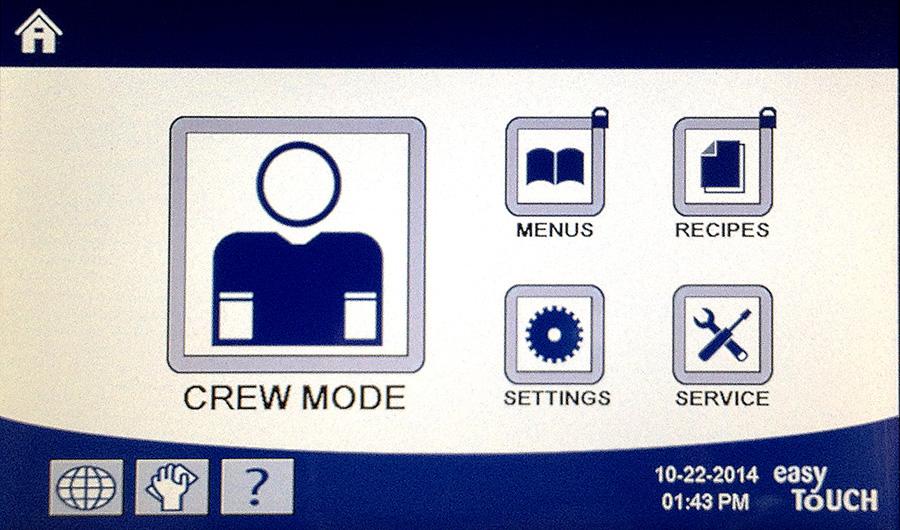
7 CHAPTER 1: FILTERQUICK FQ4000 CONTROLLER INSTRUCTIONS 1.1 FQ4000 General Information Welcome to the FQ4000, an easy to use touch screen controller with the utility of 40-product menu capability. One button push starts a cook cycle for a selected product. The controller can move seamlessly from one product to another. The FQ4000 will operate with electric and gas fryers, both full- and split-vat. 1.2 FQ4000 Button Description and Functions Navigation Buttons Main Menu Button Bar The main menu button bar at the bottom of the screen is used to navigate the various FQ4000 menus (see Figure 1). Figure Home Button The home button is used to switch to the home screen (see Figure 2). The home screen has Crew Mode, Menus, Recipes, Settings, Service, Change Language, Filter and Information Statistics buttons. Figure 2 1-1
. Figure 3 1.")
.")


8 Crew Mode Button The crew mode button switches from the home screen to the cooking mode (see Figure 3). Figure Menus Button The menus button is used to set up multiple menus with specific products such as fry station, chicken, other products, breakfast, lunch or changeover menus (See Figure 4). Figure Recipes Button The recipes button allows editing or adding of products (see Figure 5) Settings Button Figure 5 The settings button allows access to edit the settings of the fryer (see Figure 6) Service Button Figure 6 The service button allows access to service functions in the fryer (see Figure 7). During programming and other functions if no activity occurs within one minute, the controller returns to the previous operation mode. Figure 7 1-2
. 1.")
. 1.")
. When the hand is yellow, a filtration has been bypassed once.")
. 1.2.1.12 Menu Button Pressing the menu button allows switching between different menus if configured (see Figure 12).")


9 Power Button Pressing and holding the power button soft powers up the user interface and fryer. Pressing the power button when the fryer is on turns the fryer off (see Figure 8) Language Button Pressing the language button switches between a primary language and a secondary language if the feature is configured in manager settings (see Figure 9) Filter Menu Button Pressing the filter menu button provides access to the functions associated with filtering, disposing, draining, filling as well as deep cleaning the vats (see Figure 10). When the hand is yellow, a filtration has been bypassed once. When it is red, a filtration has been bypassed more than once and requires filtration. Figure 8 Figure 9 Figure Temperature Button Pressing the temperature button displays the actual vat temperature and the setpoint temperature (see Figure 11) Menu Button Pressing the menu button allows switching between different menus if configured (see Figure 12) Energy Saver Button Pressing the energy saver button switches the fryer from a standard setpoint to a lower temperature setpoint when the fryer is idle, to save energy costs (see Figure 13) Information Statistics Button Pressing the information statistics button provides information on filter statistics, oil statistics, life statistics, usage statistics, recovery time, last load statistics, and software versions (see Figure 14) Manual Oil Top Off Button Pressing the manual oil top off button allows the user to manually top off the vat of oil (see Figure 15) Escape Menu Items Figure 11 Figure 12 Figure 13 Figure 14 Figure 15 To escape or back out of MENUS and SUB-MENUS, press the Home or Back arrow button (see Figure 16) TPM (Total Polar Materials) OQS (Oil Quality Sensor) Button Pressing the TPM button when solid, displays the last 30 days of TPM/OQS readings (see Figure 17). Pressing the TPM button when blinking, denotes it has been more than 24 hours since the last OQS filter and will prompt for an OQS filter. Figure 16 Figure


10 1.3 FQ4000 Menu Summary Tree Reflected below are the major programming sections in the FQ4000 and the order in which submenu headings will be found under the sections in the Installation and Operation Manual. 1-4
11 1.4 FQ4000 Information Summary Tree Reflected below are the information statistics in the FQ4000 and the order in which submenu headings will be found in the controller. 1-5
12 1.5 Basic Operation 1-6
13 1.6 Cooking 1-7

 or Non-CE (non-european standards) SETUP COMPLETE RESTART THE 8. No action. SYSTEM 9.")
14 1.7 Fryer (Service) Setup Programming It is necessary upon initial power up or when changing out a controller to configure the parameters for the fryer. The setup includes locale, energy type, vat type, fresh oil type, waste oil type and auto top off settings. NOTE: These settings should ONLY be changed by a technician. DISPLAY 1. With the controller at the off/standby position, press the Home button. 2. Press the Settings button. 3. Press the Service button Enter Press the (check) button. LOCALE 6. Press the Locale button. 7. Select CE or NON-CE. CE (European Conformity CE NON-CE standards) or Non-CE (non-european standards) SETUP COMPLETE RESTART THE 8. No action. SYSTEM 9. Press the (check) button. ENERGY TYPE 10. Press the Energy Type button. GAS ELECTRIC 11. Select GAS or ELECTRIC SETUP COMPLETE RESTART THE 12. No action. SYSTEM 13. Press the (check) button. VAT TYPE FULL VAT SPLIT VAT 8 / Press the Vat Type button. 15. Select FULL VAT or SPLIT VAT. 16. Select Basket Configuration. Set for 8 to have 4 products per side available or 24 to have 12 products per side available. 17. Press the Product icon and choose the desired product. Repeat for other lanes. 18. Press the Save button when complete. SETUP COMPLETE RESTART THE SYSTEM 19. No action. 20. Press the (check) button. 1-8
15 21. Press the Down arrow button. OIL SYSTEM TYPE JIB BULK SETUP COMPLETE RESTART THE SYSTEM 22. Press the Oil System Type button. 23. Select JIB or BULK. NOTE: A JIB (Jug in a Box) or BIB (Bag in a Box) is a disposable type oil container. A bulk system has large storage oil tanks that are connected to the fryer that fills an onboard reservoir. 24. No action. 25. Press the (check) button. WASTE OIL DISPOSAL UNIT BULK WAND FRONT WAND EXTERNAL SETUP COMPLETE RESTART THE SYSTEM 26. Press the Waste Oil button. 27. Select DISPOSAL UNIT, BULK, WAND FRONT or WAND EXTERNAL. NOTE: Select DISPOSAL UNIT if disposing oil into an SDU or other METAL container. Select BULK if disposing oil into a bulk oil system, which has large storage oil tanks that are connected to the fryer. Select WAND FRONT if disposing using a wand connected to the fryer. Select WAND EXTERNAL if using an external dispose system using a wand with suction to extract the oil from the frypot. 28. No action. 29. Press the (check) button. AUTO TOP OFF VAT ON OFF 30. Press the Auto Top Off Vat button. 31. Select LEFT VAT or RIGHT VAT for split vats (Split Vats only). 32. Select ON unless top off is not desired for this vat. Default is ON. 33. Press the Down arrow button. ATO DELAY TIME 0 MINUTES SETUP COMPLETE ATO TYPE 34. Press the ATO Delay time button. 35. Press the time to change the delay time after the top off oil reservoir has been changed before the system begins to top off. Press the (check) button. The default is 0 minutes for liquid shortening. Enter a value greater than 0 for solid shortening. 36. Press the smaller (check) button inside the SETUP COMPLETE box. 37. Press the ATO Type button. 1-9
16 AUTO PUSH BUTTON BOTH SETUP COMPLETE FILTRATION TIME SETTINGS POLISH TIME CLEAN TIME AUTO FILTER FLUSH TIME CLEAN & FILTER FLUSH TIME OQS SETUP OQS ENABLE/DISABLE ENABLE DISABLE SETUP COMPLETE OIL TYPE OC01v01, OC02v02, etc. SETUP COMPLETE DISPLAY TYPE NUMBER TEXT SETUP COMPLETE DISCARD NOW TPM VALUE 38. Select AUTO if auto top if auto top off is installed. Select PUSH BUTTON if only manual top off is installed. Select BOTH if both auto and manual top off are installed and desired. 39. Press the (check) button inside the SETUP COMPLETE box. 40. Press the Filtration Time Settings button. 41. These settings should only be adjusted if instructed by the factory. The default settings are: POLISH TIME -300 CLEAN TIME AUTO FILTER FLUSH TIME -25 CLEAN & FILTER FLUSH TIME -25 Press the back button when complete. 42. Press the OQS Setup button if an OQS sensor is installed. 43. Press OQS ENABLE/DISABLE button to enable/disable the OQS sensor. 44. Select ENABLE to enable the OQS sensor or DISABLE to disable the OQS sensor. 45. Press the (check) button inside the SETUP COMPLETE box. 46. Press the Oil Type button. 47. Select the correct oil type curve. Press the down arrow button to scroll to additional oil type curves. Use the table on instruction sheet to determine the oil type. Ensure the oil type matches what the store is using. 48. Press the (check) button inside the SETUP COMPLETE box. 49. Press the Display Type button. 50. Select NUMBER or TEXT. NOTE: If set to NUMBER the Total Polar Materials is shown as a number. If set to Text, only DISCARD SOON/CONFIRM, OIL IS GOOD or DISCARD NOW is shown. 51. Press the (check) button inside the SETUP COMPLETE box. 52. Press the Discard Now button. 53. Press the number above TPM Value. Once the TPM (Total Polar Materials) value of the oil is attained, the fryer will prompt to discard the oil. 1-10
17 54. Use the keypad to enter the TPM discard now value. 55. Press the (check) button once the value is entered. 56. Press the (check) button to save the value. SETUP COMPLETE 57. Press the (check) button inside the SETUP COMPLETE box. 58. Press the down arrow button. DISCARD SOON TPM VALUE 59. Press the Discard Soon button. 60. Press the number above Discard Soon TPM Value. This value is typically chosen as a number below the TPM Discard Now value. This value will display the Discard Soon message when the TPM Discard Soon value is attained. This serves as a notice to the staff that the oil will need to be discarded soon. 61. Use the keypad to enter the TPM discard soon value. 62. Press the (check) button once the value is entered. 63. Press the (check) button to save the value. SETUP COMPLETE DISPOSE DELAY TIMER 64. Press the (check) button inside the SETUP COMPLETE box. 65. Press the Dispose Delay Timer button. This is the amount of time once the DISCARD NOW prompt is displayed and bypassed before the DISCARD NOW message returns. (Default is: 30 minutes. Minimum value is :00 = DISABLED, maximum value is 4:00 hours.) 66. Press the hour s box to enter a delay time in hours. 1-11
 button to save the value. SETUP COMPLETE 71. Press the (check) button inside the SETUP COMPLETE box. 72. Press the back button when complete.")
18 67. Using the key pad, enter the time in hours. 68. Press the minute s box to enter a delay time in minutes. 69. Using the key pad enter the time in minutes. 70. Press the (check) button to save the value. SETUP COMPLETE 71. Press the (check) button inside the SETUP COMPLETE box. 72. Press the back button when complete. BASIC AUTO FILTER ENABLE DISABLE SETUP COMPLETE LOW TEMP ALARM ENABLE DISABLE SETUP COMPLETE 73. Press the Basic Auto Filter button. 74. Select ENABLE Basic Auto Filter (Auto Filtration for units without OIB sensors) or DISABLE Basic Auto Filtration (Auto Filtration for units with OIB sensors). 75. Press the (check) button inside the SETUP COMPLETE box. 76. Press the Low Temp Alarm button. 77. Select ENABLE to enable the low temperature alarm or DISABLE to disable the low temperature alarm. 78. Press the (check) button inside the SETUP COMPLETE box. 79. Press the down arrow button. SEDIMENT TRAY ENABLE DISABLE SETUP COMPLETE 80. Press the Sediment Tray button. 81. Select ENABLE if using sediment trays or DISABLE if sediment trays are NOT used. 82. Press the (check) button inside the SETUP COMPLETE box. 83. Press the Home button. 84. Press the Crew Mode button. CREW MODE 1-12

 Settings Programming It is necessary upon initial power up or when changing out a controller to configure these local manager settings for the fryer.")

19 85. Press and hold the momentary reset switch. Ensure the switch is pressed and held for one (1) minute. In newer fryers the switch is located below the USB port. On older gas units, the button is located under the far-left control box. On older electric units, the button is located on the rear of the control box behind the JIB reset switch. 86. The system reboots in approximately 45 seconds and returns to off/standby mode. 1.8 Fryer (Manager) Settings Programming It is necessary upon initial power up or when changing out a controller to configure these local manager settings for the fryer. The setup includes language, date and time, temperature scale, sound settings, filter settings, energy savings, lane assignments and screen brightness. These settings should ONLY be changed by a manager or technician. DISPLAY 1. With the controller at the off/standby position, press the Home button. 2. Press the Settings button. 3. Press the Manager button Enter Press the (check) button. LANGUAGE 6. Press the Language button. 7. Press the Primary Language button. ENGLISH 8. Select the language desired. 9. Press the Secondary Language button. SPANISH 10. Select the language desired. 11. Press the Back button. DATE & TIME 12. Press the Date & Time button. 13. Press the Set Time button 14. Press the hour s box. 1-13

 button inside the SETUP COMPLETE box. 21.")


 button inside the SETUP COMPLETE box. 27.")

20 15. Using the key pad, enter the time in hours. 16. Press the minute s box. 17. Using the key pad enter the time in minutes. 18. Press the AM, PM or 24HR button. 19. Press the (check) button. SETUP COMPLETE 20. Press the smaller (check) button inside the SETUP COMPLETE box. 21. Press the Set Date button MARCH SETUP COMPLETE 22. Press the Date Format box to toggle between MM-DD-YY or DD-MM-YY. 23. At the top of the screen, the year is shown. Press the left or right arrow to select the year. 24. Below the year is the month. Press the left or right arrow to select the month. 25. Select the date using the numbered keys and press the (check) button. 26. Press the smaller (check) button inside the SETUP COMPLETE box. 27. Press the DST (DAYLIGHT SAVINGS TIME) SETUP button. DST ON/OFF 28. Press the DST ON/OFF button. 29. Select ON to enable DST or OFF to disable DST. 30. Press the smaller (check) button inside the SETUP SETUP COMPLETE COMPLETE box. DST SETTINGS 31. Press the DST SETTINGS button. DST START MONTH DST START SUNDAY DST END MONTH DST END SUNDAY 32. Select any of these and use the keypad to modify. The default settings for the US are: DST START MONTH -3 DST START SUNDAY
 button inside the SETUP COMPLETE box. 35. Press the Back button three (3) times. 36. Press the F TO C or F TO C button.")
21 DST END MONTH -11 DST END SUNDAY Press the (check) button when complete. SETUP COMPLETE F TO C CONFIRM YES NO COMPLETED SUCCESSFULLY 34. Press the smaller (check) button inside the SETUP COMPLETE box. 35. Press the Back button three (3) times. 36. Press the F TO C or F TO C button. NOTE: F is used for Fahrenheit, C is used for Celsius 37. Select YES to toggle the temperature scale. 38. Press the (check) button when complete. SOUND 39. Press the Sound button. 40. Use the up down arrows to change the volume level and tone. Volume has nine levels with 1 being the softest and 9 the loudest. Tone has three frequencies from 1-3. Use different frequencies to customize the sound. 41. Press the (check) button when complete. SETUP COMPLETE 42. Press the smaller (check) button inside the SETUP COMPLETE box. 43. Press the Down button. FILTER ATTRIBUTES FILTER AFTER 44. Press the Filter Attributes button. The auto filtration mode uses two measures before prompting to filter. One checks for cook cycles which is adjusted in the FILTER AFTER setting and the other checks for time which is adjusted in the following section FILTER TIME setting. The prompt for filtration is initiated by whichever occurs first; either the number of cycles elapsed or time elapsed. 45. Press the FILTER AFTER button. The FILTER AFTER option is used to set the number of cooking cycles which occur before the filtration prompt is displayed. 46. Press the (check) button to continue or press the number button and enter the number of cooks and press the (check) button 47. Press the (check) button. 1-15

 button to continue or press the number button and enter the number of hours in between filter prompts. (ex. after every two hours, enter as 2) and press the (check) button.")
22 SETUP COMPLETE FILTER TIME 48. Press the smaller (check) button inside the SETUP COMPLETE box. 49. Press the Filter Time button. The Filter Time option is used to set the elapsed time before a filtration prompt. This option is useful in lower volume stores, where filtration is desired more often than the amount the cook cycles would generate. 50. Press the (check) button to continue or press the number button and enter the number of hours in between filter prompts. (ex. after every two hours, enter as 2) and press the (check) button. (By default, the time is set to 0 hours.) 51. Press the (check) button. SETUP COMPLETE FILTER OFF TIME FILTRATION OFF SETTINGS 52. Press the smaller (check) button inside the SETUP COMPLETE box. 53. Press the Filter Off Time button. The Filter Off Time option is used to set times in which the filter prompt is disabled (ex. noon rush). 54. Select ON to enable FILTER OFF TIME. Select OFF to disable FILTER OFF TIME. 55. Press the Filtration Off Settings button. The Filtration Off Settings option is used to set the times in which the filter prompt is disabled (ex. noon rush). NOTE: If FILTER OFF TIME is disabled (OFF), this option is grayed out and not available. 56. Use the up down arrows to scroll between M-F 1 thru SUN 4. There are a total of 12 periods which can be programmed for filter prompt lockout. Select the field to edit the start and stop times of when the filter prompt should be suspended. Select AM/PM. Once the times are selected press the check button to save the setting. (The example at the left shows on Monday Friday no filtering is desired during a lunch rush from 11:00 AM until 2:00 PM.) 57. Once the times are selected press the (check) button. SETUP COMPLETE 58. Press the smaller (check) button inside the SETUP COMPLETE box. 59. Press the Down button. CLEAN SETUP COMPLETE RESTART THE 60. Press the Clean button. Choose HOT (Boil Out) or COLD (Cold Soak). 61. Press the (check) button. 1-16
 minutes.) 65.")

23 SYSTEM QUICK FILTER SETTINGS INTIAL DELAY TIME 62. Press the Quick Filter Settings button. 63. Press the Initial Delay Time button. 64. Press the minute s box to adjust the initial delay time. The initial delay time is the time the fryer sits idle, after filter after or filter cooks have been completed, before prompting for a filter. (Default is two (2) minutes.) 65. Using the key pad enter the time in minutes. 66. Press the (check) button. SETUP COMPLETE SKIPPED DELAY TIME 67. Press the smaller (check) button inside the SETUP COMPLETE box. 68. Press the Skipped Delay Time button. 69. Press the minute s box to adjust the skipped delay time. The skipped delay time is the time after the initial filter is skipped before it prompts again to filter. The first time the filter is skipped the filter button turns from white to yellow. The next time the filter is skipped, the filter button turns from yellow to red until the filter is performed. (Default is five (5) minutes.) 70. Using the key pad enter the time in minutes. 71. Press the (check) button. SETUP COMPLETE 72. Press the smaller (check) button inside the SETUP COMPLETE box. 73. Press the Back button two (2) times. ENERGY SAVINGS 74. Press the Energy Savings button. The Energy Savings option is used during idle periods to lower the frypot temperature to save energy. 1-17
24 75. Press the Enable button to toggle the Energy Saving option on or off. 76. Press the Set Back Temp button to change the setpoint of the Energy Saving option. Use the number pad to enter the Energy Saving setpoint temperature and press the (check) button. 77. Press the Idle Time button to change the amount of time in minutes the vat sits idle before automatically entering the Energy Saving mode. Use the number pad to enter the Energy Saving setpoint temperature and press the (check) button. 78. Press the (check) button. SETUP COMPLETE LANE ASSIGNMENTS Press the smaller (check) button inside the SETUP COMPLETE box. 80. Press the Lane Assignments button. This is used to set the number of products per vat. 81. Press the 6 button to have 12 products per vat (6 per side) available, or 2 button to have 2 products per side (4 per vat) available. 82. Press the icon below each lane and choose the associated product to cook in that lane. 83. Press the save button. SETUP COMPLETE RESTART THE SYSTEM BRIGHTNESS 84. No action. 85. Press the smaller (check) button inside the SETUP COMPLETE RESTART THE SYSTEM box. 86. Press the Brightness button. This is used to set the brightness of the screen. Use the up down arrows to adjust. (Default is 100.) 87. Press the (check) button. SETUP COMPLETE SCREEN SAVER 88. Press the smaller (check) button inside the SETUP COMPLETE box. 89. Press the Screen Saver button. This is used to set the amount of time, after the controller is turned off, before going into a screen saver mode. Use the up down arrows to adjust time. (Default is 15 minutes.) 90. Use the up down arrows to change the brightness of the screen. Brightness has nine levels with 100 being the brightest and 10 the darkest. 1-18
25 91. Press the (check) button when complete. SETUP COMPLETE ALARM ATTRIBUTES SHAKE ALARM MODE SETUP COMPLETE RESTART THE SYSTEM 92. Press the smaller (check) button inside the SETUP COMPLETE box. 93. Press the Alarm Attributes button 94. Press the Shake Alarm Mode button. Select Auto or Manual. The Shake Alarm Mode allows the user to select between auto or manual shake alarm cancel. 95. Press the (check) button. HOLD ALARM MODE SETUP COMPLETE RESTART THE SYSTEM 96. Press the Hold Alarm Mode button. Select Auto or Manual. The Hold Alarm Mode allows the user to select between auto or manual hold alarm cancel. 97. Press the (check) button. ALARM TIMER SETUP COMPLETE RESTART THE SYSTEM 98. Press the Alarm Timer button. These settings allow the user to select the amount of time before auto cancelling the shake alarm timer or hold alarm. Default settings are 5 seconds. 99. Press the (check) button Press the Back button two (2) times. TEMPERATURE ENABLE DISABLE SETUP COMPLETE OIL DRAGOUT FLOW 101. Press the Temperature button Select enable to enable the temperature button. Select disable to disable the temperature button and display constant temperature display Press the (check) button The Oil Drag out function sets parameters that adjust flow and flow adjust. These parameters are used to calculate oil drag out usage for statistical information that is captured in the Information Statistics function under Oil statistics Enter the oil drag out flow rate of pounds per minute (Default is 2.211) and press the (check) button. (Note: Enter values from for ranges lbs). 1-19
. 108. Press the (check) button when complete. 109. Press the Down button. BASKET LIFT SETUP COMPLETE RESTART THE SYSTEM 110.")
 minute.")

26 SETUP COMPLETE 106. Press the (check) button when complete. FLOW ADJUST SETUP COMPLETE 107. Enter the configurable flow rate (Default is 1) and press the (check) button. (Note: Enter values from for ranges lbs) Press the (check) button when complete Press the Down button. BASKET LIFT SETUP COMPLETE RESTART THE SYSTEM 110. Press the Basket Lift button Select ON to enable the basket lift or OFF to disable the basket lift Press the (check) button Press the Back button Press the Home button. CREW MODE 115. Press the Crew Mode button Press and hold the momentary reset switch. Ensure the switch is pressed and held for one (1) minute. On gas units, the button is located under the far-left control box. On electric units, the button is located on the rear of the control box behind the JIB reset switch The system reboots in approximately 45 seconds and returns to off/standby mode. 1.9 Adding or Editing Existing Products This function is used to add additional products or edit existing products. DISPLAY 1. Press the Home button. 2. Press the Recipes button Enter

 button. 9.")


27 4. Press the (check) button. 5. Choose the product icon to edit or press the + to add a new product. 6. Press the pencil icon at the bottom of the screen to edit an existing product. 7. Enter or change the name of the product using the keyboard. 8. Press the (check) button. 9. This screen displays the current setpoint, cook time, sensitivity, hold timer, shake timers and filter settings. To edit a parameter, press the item to edit. 10. To edit temperature, press the temp button. 11. Use the keypad to enter or edit the cook temperature for the product. 12. Press the (check) button. 13. Press the cook time button. 14. Use the keypad to enter or edit the cook time in minutes and seconds. 15. Press the (check) button. 1-21
28 16. Press the load compensation or sensitivity button. 17. Use the up and down arrows to change the load compensation or sensitivity setting recommended for this product. This setting allows the product compensation (sensitivity) to be changed. Some menu items may need an adjustment, depending on their cooking characteristics. NOTE: It is highly recommended to NOT adjust this setting, as it could have an adverse effect on the products cooking cycles. (The default setting for product compensation is set to four (4).) 18. Press the (check) button. 19. Press the Hold Timer button. 20. Enter the time in minutes and seconds for the product hold time. 21. Press the (check) button. 22. Press the Shake Timer 1 button. 23. Enter the time in minutes and seconds for the first shake to be performed. 24. Press the (check) button. 25. Press the down arrow to scroll to more settings. 26. Press the Shake Timer 2 button if an additional shake is needed, otherwise skip to step

 button. 32.")
 button. 34.")
 button. 36. The controller displays SAVED. 37. Press the (check) button. 38.")
29 27. Enter the time in minutes and seconds for the seconds shake to be performed. 28. Press the (check) button. 29. Press the Filter button. 30. Ensure that the filter button is ON to enable auto filtration for this product. This setting is used to prevent co-mingling of product specific oils. For products such as FISH, select NO to prevent auto filtration if desired. 31. Press the (check) button. 32. Choose the icon to associate with the product recipe that is being entered or edited. 33. Press the (check) button. 34. Choose the menu(s) to associate with the product recipe that is being entered or edited. 35. Press the (check) button. 36. The controller displays SAVED. 37. Press the (check) button. 38. Select another product to edit or press the + key to add additional products. If finished press the home button. CREW MODE 39. Press the Crew Mode button to return to main screen. 1-23

 button. If deleting a menu, highlight the menu and press the trash can at the bottom of the screen. 6.")

30 1.10 Adding or Editing Menus This function is used to add or edit menus. Menus allow the operator to group certain products together. For example, setting up a breakfast menu allows grouping of breakfast only products. This is helpful when switching products by narrowing the number of products to choose from. DISPLAY 1. Press the Home button. 2. Press the Menus button Enter Press the (check) button. 5. Select a menu by pressing the button above the ON/OFF button to edit products (highlighted in green) or press the + button to add a new menu. If adding a new menu, enter name of menu on next screen and press the (check) button. If deleting a menu, highlight the menu and press the trash can at the bottom of the screen. 6. Press the pencil icon at the bottom of the screen to edit an existing menu. 7. Select the desired products by pressing their icons to be added to the chosen menu. The selected products will be highlighted in green. To unselect a product, press the icon and the highlight will change from green to gray. 8. Press the (check) button when finished to save selected products to menu. 9. Press the Back button to edit additional menus starting with step 5, otherwise advance to the next step 10. Press the Home button. CREW MODE 11. Press the Crew Mode button. 1-24


31 1.11 Changing Menus If separate menus are created for Fry Station, Chicken or Other Product, pressing the MENU button from the main screen shall display menu change options. Pressing the desired menu shall switch the menus. DISPLAY 1. Press the Menu button. 2. Press the ON/OFF button under the desired menu to switch menus. Once the desired menu is selected, ON it is highlighted under the menu. NOTE: Only one menu can be selected at a time. 3. Press the back button to return to the main screen. 4. Press the product icon to switch products. 5. Display returns to main screen. 1-25

 without the second high-limit tripping and the controller displays HIGH LIMIT FAILURE DISCONNECT POWER")
32 1.12 Service Tasks Covered in this section are crew and manager service tasks used in stores such as High Limit Test, E-Log (error log), password setup, and functions to copy menus to and from the fryer from USB using menu connect High Limit Test The high-limit test mode is used to test the high limit circuit. The high-limit test will destroy the oil. It should only be performed with old oil. Shut the fryer off and call for service immediately if the temperature reaches 460 F (238 C) without the second high-limit tripping and the controller displays HIGH LIMIT FAILURE DISCONNECT POWER with an alert tone during testing. The test is cancelled at any time by turning the fryer off. When the fryer is turned back on, it returns to the operating mode and displays the product. DISPLAY 1. With the controller at the off/standby position, press the Home button. 2. Press the Service button. 3. Press the Crew button. 4. Select LEFT VAT or RIGHT VAT for split vats. PRESS AND HOLD 5. Press and hold the Press and Hold button to begin high limit test. RELEASE 6. While pressing and holding the button the vat begins to heat. The controller displays the actual vat temperature during the test. When the temperature reaches 410 F ± 10 F (210 C ± 12 C)*, the controller displays HOT HI-1 (ex. 410F) and continues heating. *NOTE: In controllers used in the European Union (those with the CE mark), the temperature is 395 F (202 C) when the controller displays HOT HI-1. HOT HI-1 7. While continuing to press and hold the button, the fryer continues heating until the high limit opens. Generally, this happens once the temperature reaches 423 F to 447 F (217 C to 231 C) for non- CE high limits and 405 F to 426 F (207 C to 219 C) for CE high limits. HELP HI-2 8. Release the button. The vat stops heating and the controller displays the current temperature setting until the temperature cools below 400 F (204 C). Press the power button to cancel the alarm. HIGH LIMIT FAILURE DISCONNECT POWER 9. If the controller displays this message, disconnect power to the fryer and immediately call for service. 10. After a high limit test, once the vat cools below 400 F (204 C), dispose of the oil. 1-26

33 Manager Functions E-Log The E-LOG function is used to view the ten (10) most recent error codes encountered on the fryer. These codes are displayed with the most recent errors displayed first. The error code, time and date are displayed. If no errors exist, the controller is blank in this function. Errors are displayed with the side of the error if a split vat, error code, time and date. An error code displaying an L indicates left side of a split vat while an R indicates right side of a split vat where the error occurred (R E19 06:34AM 04/22/2014). An error code displaying a G indicates this was a global error not specifically linked to a particular vat. Error codes are listed in section of this manual. DISPLAY 1. Press the Home button. 2. Press the Service button Enter Press the Manager button. 5. Press the (check) button. E-LOG 6. Press the E-LOG button. The three most recent errors are shown. 7. Press the Down button. The next three errors are shown. Continue pressing the down arrow to view additional errors. 8. Press the Back button to return to menu or press the Home button to exit. CREW MODE 9. Press the Crew Mode button Passcode Setup The password mode allows a restaurant manager to change passwords for various modes. DISPLAY 1. Press the Home button. 2. Press the Service button Enter Press the Manager button. 5. Press the (check) button. 1-27
 button. RETYPE PASSWORD 10.")
34 PASSCODE SETUP MENUS RECIPES SETTINGS MANAGER DIAGNOSTICS MANAGER 6. Press the PASSCODE SETUP button. 7. Select the desired passcode to modify. Use the down arrow to scroll to additional setting. Defaults are: MENUS 1650 RECIPES 1650 SETTINGS MANAGER 1656 DIAGNOSTICS MANAGER Use the keypad to enter new passcode for the selected item. 9. Press the (check) button. RETYPE PASSWORD 10. Use the keypad to enter the new passcode again to verify. 11. Press the (check) button. PASSCODE SETUP SUCCESSFUL 12. Press the (check) button. MENUS RECIPES SETTINGS MANAGER DIAGNOSTICS MANAGER 13. Press the Back button to return to menu or press the Home button to exit. 14. Press the Crew Mode button. CREW MODE USB Menu Operation This option allows the ability to upload menus to the controller. This allows products to be created in MenuSync to be saved to a USB drive and uploaded to the fryer. DISPLAY 1. Press the Home button. 2. Press the Service button Enter Press the Manager button. 1-28

35 5. Press the (check) button. USB MENU OPERATION COPY MENU FROM USB TO FRYER INSERT USB IS USB INSERTED? YES NO READING FILE FROM USB PLEASE DO NOT REMOVE USB WHILE READING MENU.CBR or other *.cbr file UI-UI MENU DATA TRANSFER IN PROGRESS MENU UPGRADE IN PROGRESS UPGRADE COMPLETE? YES MENU UPGRADE COMPLETED, REMOVE THE USB AND RESTART THE SYSTEM. 6. Press the USB MENU OPERATION button. 7. Press the COPY MENU FROM USB TO FRYER button. 8. Insert the USB drive into the connector behind the farleft fryer door. 9. Press YES once the USB drive is inserted. 10. No action required. 11. A list appears with a list of menu files ending in.cbr. Select the menu file to load. 12. No action required while the file is loading. 13. No action required while the upgrade is in progress. 14. Press YES. 15. Remove the USB drive and power cycle the entire fryer battery using the reset switch behind the far-left fryer door below the USB connector. NOTE: Ensure the switch is pressed and held for at least one (1) minute Information Statistics Report Card Statistics The report card statistics function is used to view a quick report on filtering, OQS, oil quality and frypot utilization. DISPLAY 1. Press the Information button. 2. Press the Report Card button. TODAY S REPORT YESTERDAY S REPORT WEEKLY REPORT 3. Select the desired report 1-29


36 4. The report will display the grade based on if the crew is filtering when prompted; if OQS is being measured regularly; the current quality of the oil; and the fryer usage. 5. Press the back button to return to menu or the home button to exit Oil Statistics The oil statistics function is used to view the date of last dispose, the number of cooks since last dispose, filters since last dispose, skipped filters since last dispose, current oil life and average number of cooks over the oil life. DISPLAY 1. Press the Home button and then the Information button. 2. Press the Oil button. 1. LAST DISPOSE DATE 2. COOKS SINCE LAST DISPOSE 3. FILTERS SINCE LAST DISPOSE 4. SKIPPED FILTERS SINCE LAST DISPOSE 3. Press the down arrow to scroll to more statistics. 5. CURRENT OIL LIFE 6. AVERAGE COOKS OVER OIL LIFE 7. DAILY DISPOSE BYPASS COUNT 8. OIL DRAGOUT PER DISPOSE 9. OIL DRAGOUT PER DAY 10. OIL DRAGOUT PER HOUR 4. Press the up arrow to scroll up; the back button to return to menu or the home button to exit. 1-30

 5. TOTAL HEAT CYCLE COUNT 6.")


37 Life Statistics The life statistics function is used to view the commission date of the fryer which is automatically set once the fryer has completed 25 cooks, the serial number of the controller, the total time the fryer has operated in hours and the total heat cycle count of the fryer (the amount of times the controller has turned the heat on/off). DISPLAY 1. Press the Home button and then the Information button. 2. Press the Life Stats button. 1. COMMISSION DATE 2. UNIT SERIAL NUMBER 3. CONTROLLER SERIAL NUMBER 4. TOTAL ON TIME (HOURS) 5. TOTAL HEAT CYCLE COUNT 6. TOTAL ENERGY SAVING TIME 7. TOTAL COOK TIME 3. Press the back button to return to menu or the home button to exit Usage Statistics The usage statistics displays total cook cycles per vat, number of cook cycles per vat, number of cook cycles exited prior to completion, the number of hours the vat(s) have been on and the date of last usage reset. DISPLAY 1. Press the Home button and then the Information button. 2. Press the Usage Stats button. 1. USAGE START DATE 2. TOTAL NUMBER OF COOK CYCLES 3. TOTAL NUMBER OF QUIT COOK CYCLES 4. TOTAL VAT ON TIME (HOURS) 3. Press the back button to return to menu or the home button to exit. 1-31
 between 250 F (121 C) and 300 F (149 C).")
38 Recovery Time Recovery is used to determine if the fryer is operating correctly. Recovery is the time required for the fryer to raise the temperature of the oil 50 F (28 C) between 250 F (121 C) and 300 F (149 C). Maximum recovery time should not exceed 1:40 for electric or 3:15 for gas. DISPLAY 1. LAST RECOVERY TIME 1. Press the Home button and then the Information button. 2. Press the Recovery button. The time is displayed in minutes and seconds. 3. Press the back button to return to menu or the home button to exit Filter Statistics The filter statistics function is used to view the number of cooks remaining until the next filter, the number of cooks per vat, the number of filters per vat, the number of skipped or bypassed filters per vat and the average number of cook cycles per filter per day. DISPLAY 1. Press the Home button and then the Information button. 2. Press the Filter button. DAY 1 DAY 2 DAY 3 DAY 4 3. Select and press the desired day. Press the down arrow to scroll back additional days. 1. DAY AND DATE (Day and date of filter statistics displayed) 2. COOKS REMAINING UNTIL NEXT FILTER (Number of times cooks that remain until the next filter prompt.) 3. DAILY NUMBER OF COOKS (Number of cooks that day) 4. DAILY NUMBER OF FILTERS (Number of times vat filtered that day.) 4. Press the down arrow to scroll to more statistics. 5. DAILY NUMBER OF SKIPPED FILTERS (Number of times filter was bypassed that day.) 6. AVERAGE COOKS PER FILTER - (Average number of 5. Press the up arrow to scroll up or the back button to return to select another day. 1-32
 9. FILTRATION (Displays if filtration is enabled or disabled.")

39 cook cycles per filter that day.) 7. WEEKLY NUMBER OF FILTERS - (Number of times vat filtered in the past week.) 8. WEEKLY NUMBER OF SKIPPED FILTERS (Number of times filters were bypassed in the past week.) 9. FILTRATION (Displays if filtration is enabled or disabled. Diagnostic tool to determine status of FIB board.) 6. Press the back button to return to menu or the home button to exit Software Version The software version function provides the software versions of the controller and circuit boards in the fryer system; the values of the temperature probe; the values of the AIF RTD probe and the ATO RTD probe and information on any attached gateway. DISPLAY 1. Press the Home button and then the Information button. 2. Press the down arrow button. 3. Press Software Version button. INITIALIZING 1. UIB SOFTWARE VERSION 2. SIB SOFTWARE VERSION 3. VIB SOFTWARE VERSION 4. FIB SOFTWARE VERSION 4. No action needed. 5. Press the down arrow to scroll to additional software versions and probe temperatures. NOTE: Split vats will have an SIB2 and left and right vat, AIF, and ATO temperatures. 5. OQS SOFTWARE VERSION 6. ACTUAL VAT TEMP 7. AIF RTD TEMP 8. ATO RTD TEMP 9. BOARD ID 6. Press the down arrow to scroll to additional software versions and information. 7. Press the up arrow to scroll up; the back button to return to menu or the home button to exit. 1-33
 button.")

40 10. GATEWAY SOFTWARE VERSION 11. GATEWAY IP ADDRESS 12. GATEWAY LINK QUALITY 13. GATEWAY SIGNAL STRENGTH AND NOISE Reset Usage Statistics The reset function resets all usage data in the usage statistics. DISPLAY 1. Press the Home button and then the Information button. 2. Press the down arrow button. 3. Press Reset button Enter Press the (check) button. ALL USAGE DATA HAS BEEN RESET 6. Press the (check) button. 7. Press the up arrow to scroll up; the back button to return to menu or the home button to exit Fresh Oil Statistics The fresh oil statistics function is used to view information on the current fresh oil. DISPLAY 1. Press the Home button and then the Information button. 2. Press the down arrow button. 3. Press the Fresh Oil button. 1. NUMBER OF COOKS SINCE LAST DISPOSE 2. DISPOSE COUNT COOKS SINCE LAST RESET 3. FRESH OIL COUNTER RESET DATE 4. FRESH OIL COUNTER 4. Press the back button to return to menu or the home button to exit. 1-34
 button.")


41 Fresh Oil Reset Usage Statistics The reset function resets all fresh oil data in the fresh oil statistics. DISPLAY 1. Press the Home button and then the Information button. 2. Press the down arrow button Enter Press Fresh Oil Reset button. 5. Press the (check) button. FRESH OIL DATA HAS BEEN RESET 6. Press the (check) button. 7. Press the back button to return to menu or the home button to exit Last Load Statistics The last load statistics provides data for the last cook cycle. DISPLAY 1. LAST COOKED PRODUCT 2. LAST LOAD START TIME 3. LAST LOAD COOK TIME 4. LAST LOAD PROGRAM TIME 1. Press the Home button and then the Information button. 2. Press the Last Load button. 3. Press the down arrow to scroll to more statistics. 5. LAST LOAD MAX VAT TEMP 6. LAST LOAD MIN VAT TEMP 7. LAST LOAD AVG VAT TEMP 8. % OF COOK TIME, HEAT IS ON 4. Press the down arrow to scroll to more statistics. 1-35
 Statistics The TPM statistics provides data from the OQS (Oil Quality Sensor).")
 days are listed. 5.")
42 9. VAT TEMP BEFORE COOK STARTS 10. VAT TEMP AT COOK END 5. Press the up arrow to scroll up; the back button to return to menu or the home button to exit TPM (Total Polar Material) Statistics The TPM statistics provides data from the OQS (Oil Quality Sensor). The same data can be accessed by pressing the TPM button on the front of the controller when the TPM button is solid. DISPLAY 1. Press the Home button. 2. Press the Information button. 3. Press the down arrow. 4. Press the TPM Statistics button. The TPM values for the previous valid thirty (30) days are listed. 5. Press the up arrow to scroll up; the back button to return to menu or the home button to exit. 1-36

43 CHAPTER 2: FILTERQUICK FQ4000 FILTRATION MENU FUNCTIONS INSTRUCTIONS 2.1 Filtration Menu The filtration menu selections are used for filtering, draining, filling, disposing and cleaning the vats Quick Filter Filter Prompt Quick Filter is a feature that, after a number of preset cook cycles or time, will automatically prompt to filter the frypots. This function can also be performed on demand as well and is covered in the next section. Note: Simultaneous filtering of multiple vats does not occur. DISPLAY FILTRATION REQUIRED FILTER NOW? OIL LEVEL TOO LOW SKIM DEBRIS FROM VAT START FILTRATION DRAINING FLUSHING ALERT DRAIN CLOSING REMOVE TOOLS 1. Press the (check - YES) button to start filtration. If the X (NO) button is selected, filtering is cancelled and the fryer resumes normal operation. The filtration button changes to yellow on the first bypass and the QUICK FILTER is highlighted in yellow in the filter menu. On the second bypass, the filtration button changes to red. The controller will prompt again soon to filter the oil. This sequence repeats until a filter is completed. 2. Displayed if the oil level is too low. Press the (check - YES) button to acknowledge issue and return to idle cook mode. Check to see if the JIB is low on oil. If JIB is not low and this continues to occur, contact your FAS. 3. Skim the crumbs from the oil with the skimmer using a front to back motion, removing as many crumbs as possible from each vat. This is critical to optimizing usable oil life and quality in the oil. Press the (check- YES) button when complete. Press the X button to cancel the filter. 4. Press the BLUE button to start filtration or the X button to cancel the filter. 5. No action required. 6. No action required. 7. Ensure that all tools are removed from the frypot prior to the drain closing to prevent damage to the drain. Keep all items out of drains. Closing actuators may cause damage or injury. FILLING 8. No action required. 9. No action required. Displayed until the fryer reaches PREHEAT setpoint. 10. Fryer is ready for use. Displayed once fryer reaches setpoint. The complete filtering process takes approximately four minutes with a clean filter. 2-1
44 NOTE: If the filter pan is removed during filtration, the filtration process stops and resumes once pan is reseated into place. Should the quick filtration procedure fail or if ALL the oil isn t completely returned during filtration, the system may proceed to an incomplete filtration function. In some cases, an error message may be generated. Follow the instructions on the controller to clear the error, complete the filter and return ALL the oil. Keep all items out of drains. Closing actuators may cause damage or injury Quick Filter on Demand Quick Filter on demand filtration is used to manually start a quick filter. Note: Simultaneous filtering of multiple vats cannot occur. DISPLAY 1. The fryer MUST be at setpoint temperature. Press the filtration menu button. The filtration button is yellow if a bypass has occurred. If the filtration button is red, more than one bypass has occurred. 2. Select LEFT VAT or RIGHT VAT for split vats. 3. Select QUICK FILTER. QUICK FILTER is highlighted in yellow in the filter menu if a bypass has occurred. QUICK FILTER NOW? OIL LEVEL TOO LOW SKIM DEBRIS FROM VAT START FILTRATION DRAINING 4. Press the (check - YES) button to start filtration. If the X (NO) button is selected, filtering is cancelled and the fryer resumes normal operation. 5. Displayed if the oil level is too low. Press the (check - YES) button to acknowledge issue and return to idle cook mode. Check to see if the JIB is low on oil. If JIB is not low and this continues to occur, contact your FAS. 6. Skim the crumbs from the oil with the skimmer using a front to back motion, removing as many crumbs as possible from each vat. This is critical to optimizing usable oil life and quality in the oil. Press the (check- YES) button when complete. Press the X button to cancel the filter. 7. Press the BLUE button to start filtration or the X button to cancel the filter. 8. No action required as oil drains into filter pan. 2-2

45 FLUSHING ALERT DRAIN CLOSING REMOVE TOOLS FILLING PREHEAT 9. No action required as debris is flushed from the vat. 10. Ensure that all tools are removed from the frypot prior to the drain closing to prevent damage to the drain. Keep all items out of drains. Closing actuators may cause damage or injury. 11. No action required as the vat refills. 12. No action required as the fryer heats to setpoint. 13. Fryer is ready for use. Displayed once fryer reaches setpoint. The complete filtering process takes approximately four minutes with a clean filter. NOTE: If the filter pan is removed during filtration, the filtration process stops and resumes once pan is reseated into place. Should the quick filtration procedure fail or if ALL the oil isn t completely returned during filtration, the system may proceed to an incomplete filtration function. In some cases, an error message may be generated. Follow the instructions on the controller to clear the error, complete the filter and return ALL the oil. When FILTER BUSY is displayed, the system is waiting on another vat to be filtered or waiting on another issue to clear. Press the (check - YES) button and wait 15 minutes to see if problem is corrected. If not, call your local FAS. Do not drain more than one frypot at a time into the built-in filtration unit to avoid overflow and spillage of hot oil that may cause severe burns, slipping and falling. WARNING The filter motor is equipped with a manual reset switch in case the filter motor overheats or an electrical fault occurs. If this switch trips, turn off power to the filter system and allow the pump motor to cool 20 minutes before attempting to reset the switch (see photo below). WARNING Use caution and wear appropriate safety equipment when resetting the filter motor reset switch. Resetting the switch must be accomplished with care to avoid the possibility of a serious burn from careless maneuvering around the drain tube and frypot. Filter Motor Reset Switch 2-3
46 2.1.3 Clean and Filter (with OQS [if installed]) (or End of Day Filter) The clean and filter operation is an extended filtration with additional prompts to thoroughly clean the vat. This typically is done once a day or at the end of the day. Ensure that the filter pad or paper is replaced daily to keep the system operating correctly. For proper operation in high volume or 24-hour stores, the filter pad or paper must be changed twice a day. If CLOSE DISPOSE VALVE is displayed, close the dispose valve. Press the X (NO) button to exit. DISPLAY NOTICE The filter pad or paper must be replaced daily. WARNING Do not drain more than one frypot at a time into the built-in filtration unit to avoid overflow and spillage of hot oil that may cause severe burns, slipping and falling. 1. The fryer MUST be at setpoint temperature. Press the filtration menu button. 2. Select LEFT VAT or RIGHT VAT for split vats. 3. Select CLEAN AND FILTER (WITH OQS [Oil Quality Sensor] if installed). CLEAN NOW? SKIM DEBRIS FROM VAT - WEAR PROTECTIVE GLOVES START FILTRATION 4. Press the (check - YES) button to start filtration. If the X (NO) button is selected, filtering is cancelled and the fryer resumes normal operation. 5. Skim the crumbs from the oil with the skimmer using a front to back motion, removing as many crumbs as possible from each vat. This is critical to optimizing usable oil life and quality of the oil. Press the (check - YES) button when complete. Press the X button to cancel the filter. 6. Press the (check - YES) button once all personal protection equipment including heat resistant gloves are in place. Press the X button to cancel the filter. 7. Press the BLUE button to start filtration or the X button to cancel the filter. DRAINING 8. No action required as oil drains into filter pan. 2-4
 button when complete. Keep all items out of drains.")
 button to continue. If crumbs are still present, press the (check - YES) button and the filter pump runs again.")
47 SCRUB INSIDE VAT PRESS YES WHEN COMPLETE FLUSHING FLUSH AGAIN? ALERT DRAIN CLOSING REMOVE TOOLS RINSING IN PROGRESS RINSE AGAIN? POLISHING ALERT DRAIN CLOSING REMOVE TOOLS FILLING MEASURING OIL QUALITY FILLING 9. Scrub the vat. Press the (check - YES) button when complete. Keep all items out of drains. Closing actuators may cause damage or injury. 10. No action required while the return valve opens and the vat is flushed with oil from the filter pan. 11. The filter pump shuts off. If the vat is clean of debris, press the X (NO) button to continue. If crumbs are still present, press the (check - YES) button and the filter pump runs again. This cycle repeats until the X (NO) button is pressed. 12. Ensure that all tools are removed from the frypot prior to the drain closing to prevent damage to the drain. Keep all items out of drains. Closing actuators may cause damage or injury. 13. No action required while the drain valve closes and the filter pump refills the vat. The drain valve opens and rinses the vat. 14. If the vat is clean of debris, press the X (NO) button to continue. If an additional rinse is desired, press the (check - YES) button and the rinse repeats until the X (NO) button is pressed. 15. No action required while the drain and return valves are open and oil is pumped through the frypot for five minutes. 16. Ensure that all tools are removed from the frypot prior to the drain closing to prevent damage to the drain. Keep all items out of drains. Closing actuators may cause damage or injury. 17. No action required while the vat is refilled. If an OQS sensor is installed proceed to next step, otherwise proceed to step No action required while the OQS sensor calculates the oil quality value of the oil. 19. No action required while the vat is refilled. 20. If OQS = Text and if TPM reading is below OQS SETUP DISCARD NOW and DISCARD SOON limits, the TPM value is shown in the green TPM box in lower right corner. Proceed to step 24. If OQS = Text and if TPM reading is below OQS SETUP DISCARD NOW but above DISCARD SOON limits, the TPM value is shown in the orange TPM box in lower right corner. Proceed to DISCARD SOON in step 21. If OQS = Text and if TPM reading is above OQS SETUP DISCARD NOW limits; the TPM value is shown in the red TPM box in lower right corner. Proceed to DISCARD NOW in step 2-5
 button to continue. Proceed to DISPOSE in section 2.1.5/6.")
 button once the oil level is at the top oil level full line. If the vat oil level is not completely filled, check the filter pan to see if most of the oil has returned.")
48 23. If OQS = Number proceed to TPM - XX in step 22. DISCARD SOON 21. Press the (check -YES) button to continue. Skip to step 24 TPM - XX DISCARD NOW IS FRYPOT FULL OF OIL? 22. Press the (check - YES) button to continue. If the TPM reading is above OQS SETUP DISCARD limits, proceed to step 23, otherwise proceed to step Press the (check -YES) button to continue. Proceed to DISPOSE in section 2.1.5/6. Press X (NO) to delay the DISPOSE. 24. Press the X (NO) button to run the pump again if the oil level is below the top oil level full line. * Press the (check - YES) button once the oil level is at the top oil level full line. If the vat oil level is not completely filled, check the filter pan to see if most of the oil has returned. The pan may have a small amount of oil. 25. The controller switches off. *NOTE: After a clean and filter it is normal to leave some oil in the pan and the level of oil may not return to the level prior to starting clean and filter. Answering YES after two attempts at refilling the vat enables auto top off, if available, to compensate for any loss of oil during filtration OQS (Oil Quality Sensor) Filter The OQS filter is a function that filters the vat that takes an oil reading to test the TPM (Total Polar Materials) in the oil using the built in OQS sensor. This function is used to determine when the oil has reached the end of its life and when to dispose. Ensure that the filter pad or paper is replaced daily to keep the system operating correctly. For proper operation in high volume or 24- hour stores, the filter pad or paper must be changed twice a day. If CLOSE DISPOSE VALVE is displayed, close the dispose valve. Press the X (NO) button to exit. DISPLAY NOTICE The filter pad or paper must be replaced daily. WARNING Do not drain more than one frypot at a time into the built-in filtration unit to avoid overflow and spillage of hot oil that may cause severe burns, slipping and falling. 1. The fryer MUST be at setpoint temperature. Press the filtration menu button or if the TPM button is blinking, press the TPM button. 2-6
 button to start filtration.")
49 2. Select LEFT VAT or RIGHT VAT for split vats. 3. Select ADVANCED FILTER OPTIONS. 4. Select OQS (Oil Quality Sensor) - FILTER. OQS FILTER NOW? OIL LEVEL TOO LOW SKIM DEBRIS FROM VAT START FILTRATION DRAINING FLUSHING ALERT DRAIN CLOSING REMOVE TOOLS FILLING MEASURING OIL QUALITY FILLING 5. Press the (check - YES) button to start filtration. If the X (NO) button is selected, filtering is cancelled and the fryer resumes normal operation. 6. Displayed if the oil level is too low. Press the (check - YES) button to acknowledge issue and return to idle cook mode. Check to see if the JIB is low on oil. If JIB is not low and this continues to occur, contact your FAS. 7. Skim the crumbs from the oil with the skimmer using a front to back motion, removing as many crumbs as possible from each vat. This is critical to optimizing usable oil life and quality of the oil. Press the (check- YES) button when complete. Press the X button to cancel the filter. 8. Press the BLUE button to start filtration or the X button to cancel the filter. 9. No action required as oil drains into filter pan. 10. No action required while the return valve opens and the vat is flushed with oil from the filter pan. 11. Ensure that all tools are removed from the frypot prior to the drain closing to prevent damage to the drain. Keep all items out of drains. Closing actuators may cause damage or injury. 12. No action required while the vat is refilled. 13. No action required while the OQS sensor calculates the oil quality value of the oil. 14. No action required while the vat is refilled. 15. If OQS = Text and if TPM reading is below OQS SETUP DISCARD NOW and DISCARD SOON limits, the TPM value is shown in the green TPM box in lower right corner. Proceed to step 20. If OQS = Text and if TPM reading is below OQS SETUP DISCARD NOW but above DISCARD SOON limits, the TPM 2-7

 button to continue. Proceed to DISPOSE in section 2.1.5/6.")

50 DISCARD SOON value is shown in the orange TPM box in lower right corner. Proceed to DISCARD SOON in step 16. If OQS = Text and if TPM reading is above OQS SETUP DISCARD NOW limits; the TPM value is shown in the red TPM box in lower right corner. Proceed to DISCARD NOW in step 18. If OQS = Number proceed to TPM - XX in step Press the (check -YES) button to continue. Skip to step 20 TPM - XX DISCARD NOW PREHEAT 17. Press the (check - YES) button to continue. If the TPM reading is above OQS SETUP DISCARD limits, proceed to step 18, otherwise proceed to step Press the (check -YES) button to continue. Proceed to DISPOSE in section 2.1.5/6. Press X (NO) to delay the DISPOSE. 19. No action required as the fryer heats to setpoint. 20. Fryer is ready for use. Displayed once fryer reaches setpoint. NOTE: If the oil isn t completely returned during filtration, the system may proceed to an incomplete filtration function Dispose for Non-Bulk Oil Systems This option is used to dispose of old oil into either a SDU or a METAL container. When cooking oil is exhausted, dispose the oil into an appropriate container for transport to the waste oil container. Frymaster recommends a Shortening Disposal Unit (SDU). Refer to the documentation furnished with your disposal unit for specific operating instructions. NOTE: If using an SDU built before January 2004, the unit will not fit under the drain. If a shortening disposal unit is not available, allow the oil to cool to 100 F (38 C), then drain the oil into a METAL container with a capacity of FOUR gallons (15 liters) or larger to prevent oil from spilling. DISPLAY 1. Press the filtration menu button. 2. Select LEFT VAT or RIGHT VAT for split vats. 2-8
51 3. Select DISPOSE 4. Press the (check - YES) button to continue. If the X (NO) button is selected, the user returns to the previous state. DISPOSE NOW? REMOVE FILTER PAN IS FILTER PAN EMPTY? INSERT DISPOSAL UNIT Allow oil to cool to 100 F (38 C) before draining into an appropriate METAL container for disposal. 5. Carefully remove the filter pan from the fryer. Remove the filter pan slowly to avoid splashing of hot oil that may cause severe burns, slipping and falling. 6. If the filter pan is empty press the (check - YES) button. If the pan is not empty, press the X (NO) button and return to previous state and use the FILL VAT FROM PAN function to return the oil to the vat. 7. Carefully remove the filter pan from the fryer and insert the disposal unit. Remove the filter pan slowly to avoid splashing of hot oil that may cause severe burns, slipping and falling. When draining oil into a disposal unit, do not fill above the maximum fill line located on the container. 8. Ensure the SDU or a METAL container with a capacity of FOUR gallons (15 liters) or larger is in place. Press the (check - YES) button to continue. IS DISPOSE UNIT IN PLACE? Allow oil to cool to 100 F (38 C) before draining into an appropriate METAL container for disposal. When draining oil into an appropriate SDU or METAL container, make sure the container will hold at least FOUR gallons (15 liters) or more. Otherwise oil could overflow and can cause injury. START DISPOSE DISPOSING IS FRYPOT EMPTY? 9. Press the BLUE button to start filtration or the X button to cancel the dispose. 10. No action is required while the vat disposes the oil. 11. Once the frypot is empty, press the (check - YES) button to continue. 2-9
52 SCRUB FRYPOT COMPLETE? ALERT DRAIN CLOSING REMOVE TOOLS FILL VAT FROM BULK? START FILLING? PRESS AND HOLD RELEASE BUTTON WHEN FULL CONTINUE FILLING? REMOVE DISPOSAL UNIT? INSERT FILTER PAN MANUALLY FILL VAT 12. Clean the frypot with a scrub brush and when complete press the (check - YES) button to continue. 13. Ensure that all tools are removed from the frypot prior to the drain closing to prevent damage to the drain. Keep all items out of drains. Closing actuators may cause damage or injury. If using a JIB fresh oil system skip to step 18. If using a bulk fresh oil system type, continue to next step. 14. Press the (check - YES) button to continue. If the X (NO) button is selected, the user returns to the filtration menu. 15. Press and hold the button to fill the vat. The bulk oil refill pump uses a momentary switch. It only pumps if the switch is depressed. 16. Release the button when the vat is filled to the lower fill line. 17. Press the (check - YES) button to continue filling. Otherwise press the X (NO) button once the vat is full, to exit and skip to step Remove the disposal unit and press the (check - YES) button to continue. 19. Insert the clean and assembled filter pan into place. 20. Carefully pour oil into the vat until it reaches the low-level fill line in the fryer. Press the (check - YES) button once the vat is full. 21. The controller switches off. Reinsert the filter pan Dispose for Bulk, Wand Front, and Wand External Dispose Waste Oil Systems This option is used to dispose of exhausted oil into a bulk waste oil system. Bulk oil systems use a pump to move exhausted oil from the fryer to a holding tank. Additional plumbing is used to connect the bulk oil systems to the fryers. Wand Front Dispose systems use a wand, that is connected to the front of the fryer, to pump the oil into a disposal container. Wand External Dispose systems use a wand, with an external pump, that pumps the oil from the frypot. DISPLAY WARNING Ensure filter paper or pad is in place prior to draining or disposing of oil. Failure to insert filter paper or pad may result in clogged lines and/or pumps. 1. Press the filtration menu button. 2-10
53 2. Select LEFT VAT or RIGHT VAT for split vats. 3. Select DISPOSE. If disposing to bulk proceed to the next step. If using a front dispose (Wand Front) system, skip to step 5. If using an external wand system to pump the oil from the fryer, skip to step 6. DISPOSE NOW? IS DISPOSE FROM FILTER PAN WITH WAND? IS DISPOSE FROM FRYPOT WITH WAND? IS WAND DISPOSAL SYSTEM IN PLACE? REMOVE FILTER PAN IS FILTER PAN EMPTY? INSERT FILTER PAN START DISPOSE BULK TANK FULL? INSERT FILTER PAN DRAINING IS FRYPOT EMPTY? SCRUB FRYPOT COMPLETE? ALERT DRAIN CLOSING REMOVE TOOLS 4. Press the (check - YES) button to continue and skip to step 8. If the X (NO) button is selected, the user returns to the previous state. 5. Press the (check - YES) button to continue and skip to step 8. If the X (NO) button is selected, the user returns to the previous state. 6. Press the (check - YES) button to continue and skip to step 7. If the X (NO) button is selected, the user returns to the previous state. 7. Ensure the external wand disposal system is in place and press the (check - YES) button to continue and skip to step Remove the filter pan. 9. If the filter pan is empty press the (check - YES) button and proceed to the next step. If the pan is not empty, press the X (NO) button. The clean function is cancelled and returns to the filtration menu. Remove the oil from the pan and after inserting the filter pan, retry the function. If no pan is detected, the controller displays INSERT PAN until the pan is detected. 10. Push the filter pan fully into place and continue to next step. Displayed if the filter pan is not fully engaged. 11. Press the BLUE button to start filtration or the X button to cancel the dispose. If using an external wand skip to step This message is only displayed if the bull tank is full. Press the (check - YES) button to acknowledge and call the bulk oil waste provider. The display returns to OFF. 13. Push the filter pan fully into place. Displayed if the filter pan is not fully engaged. 14. No action required as oil drains into filter pan. 15. Once the frypot is empty, press the (check - YES) button to continue. 16. Clean the frypot with a scrub brush and when complete press the (check - YES) button to continue. 17. Ensure that all tools are removed from the frypot prior to the drain closing to prevent damage to the drain. If using front dispose (Wand Front) proceed to the next step. If disposing to bulk skip to step
54 Keep all items out of drains. Closing actuators may cause damage or injury. POSITION DISPOSAL UNIT IS DISPOSE WAND AND DISPOSAL UNIT IN PLACE? 18. Position the disposal unit in front of the fryer and press the (check - YES) button to continue. 19. Attach the dispose wand by pulling back on the female end collar and pushing firmly onto the male disconnect. Once in place, release the disconnect and ensure that the quick disconnect is fully locked into place. Ensure the disposal unit is in place in front of the fryer and press the (check - YES) button to continue. When draining oil into an appropriate METAL container, make sure the container will hold at least FOUR gallons (15 liters) or more, otherwise hot liquid could overflow and cause injury. OPEN DISPOSE VALVE PRESS AND HOLD THE FRONT WAND SWITCH 20. Open the left cabinet door and unlock the valve if necessary. Pull the dispose valve completely forward to start disposal. If using front dispose continue to next step. 21. Ensure the wand is in place prior to pressing and holding the dispose switch to start disposing. DISPOSING RELEASE WAND SWITCH AND CLOSE DISPOSE VALVE WHEN FULL 22. The oil transfers from the filter pan to the disposal unit. When the pan is empty, release the switch to stop the pump. Close the dispose valve when full by pushing the valve handle toward the rear of the fryer until it stops. Relock the valve if required by your manager. Skip to step 27. USE WAND TO EXTRACT OIL FROM FRYPOT 23. Use the external wand to pump oil from the frypot to the disposal unit. Press (check - YES) button when complete and proceed to the next step. 2-12
55 OPEN DISPOSE VALVE 24. Open the left cabinet door and unlock the valve if necessary. Pull the dispose valve completely forward to start disposal and continue to next step. DISPOSING IS FRYPOT EMPTY? REMOVE FILTER PAN IS FILTER PAN EMPTY? USE WAND TO EXTRACT OIL FROM THE FILTER PAN REMOVE WAND DISPOSAL SYSTEM CLEAN FILTER PAN? SCRUB FRYPOT COMPLETE? IS FILTER PAN DRY? INSERT FILTER PAN REMOVE DISPOSAL UNIT AND DETACH WAND 25. No action is required while the pump transfers the waste oil from the pan to the waste container. If disposing to bulk proceed to step 27. If using an external wand to pump oil from the frypot proceed to the next step. 26. Once the frypot is empty, press (check - YES) button when complete and proceed to the next step. 27. Carefully pull the filter pan from the fryer. Open the filter pan slowly to avoid splashing of hot oil that may cause severe burns, slipping and falling. 28. If the filter pan is empty press the (check - YES) button. If using front wand dispose continue to step 31. If disposing to bulk skip to step 34. If disposing to external wand skip to step 30. If the pan is not empty, press the X (NO) button; return to step 20 for front dispose; step 24 for bulk; or step 30 for external wand. If the filter pan is not empty and using an external wand continue to next step. 29. Use the external wand to pump oil from the filter pan to the disposal unit. Press (check - YES) button when complete and proceed to the next step. 30. Remove the external wand disposal system and skip to next step. 31. Clean the filter pan and press (check - YES) button when complete and skip to step 33. If using an external wand, proceed to next step. 32. Clean the frypot with a scrub brush and when complete press the (check - YES) button to continue. 33. Dry the filter pan and press (check - YES) button when complete. 34. Insert the filter pan. If using front wand dispose continue to next step. If disposing to bulk skip to step 36. If using an external wand skip to step Disconnect the disposal wand and remove the disposal unit and press (check - YES) button when complete. If using a JIB fresh oil system skip to step 41. If using a bulk fresh oil system type, skip to step
56 CLOSE DISPOSE VALVE 36. Close the dispose valve by pushing the valve handle toward the rear of the fryer until it stops. Relock the valve if required by your manager. If using a JIB fresh oil system skip to step 41. If using a bulk fresh oil system type, continue to next step. FILL VAT FROM BULK? START FILLING? PRESS AND HOLD RELEASE BUTTON WHEN FULL CONTINUE FILLING? MANUALLY FILL VAT 37. Press the (check - YES) button to continue. If the X (NO) button is selected, the user returns to the filtration menu. 38. Press and hold the button to fill the vat. The bulk oil refill pump uses a momentary switch. It only pumps if the switch is depressed. 39. Release the button when the vat is filled to the lower fill line. 40. Press the (check - YES) button to continue filling. Otherwise press the X (NO) button once the vat is full, to skip to step Carefully pour oil into the vat until it reaches the low-level fill line in the fryer. Press the (check - YES) button once the vat is full. 42. The controller switches off Fill Vat from (Filter) Pan The fill vat from pan function fills the vat from the filter pan. DISPLAY 1. The fryer MUST be OFF. 2. Press the filtration menu button 3. Select LEFT VAT or RIGHT VAT for split vats. 4. Select ADVANCED FILTER OPTIONS. 5. Select FILL VAT FROM PAN. If no pan is detected, the controller displays INSERT PAN until the pan is detected. 2-14
57 FILL FROM PAN? FILLING IS FRYPOT FULL OF OIL? 6. Press the (check - YES) button to continue. If the X (NO) button is selected, the controller goes to OFF. 7. No action is required while the vat is filling. 8. Press the X (NO) button to run the pump again if the oil level is below the top oil level full line. Press the (check - YES) button once the oil level is at the top oil level full line. If the vat oil level is not completely filled, check the filter pan to see if most of the oil has returned. The pan may have a small amount of oil. 9. The controller switches off Fill Vat from Bulk The fill vat from bulk function is used to fill the vat from a bulk oil fresh source. DISPLAY 1. The fryer MUST be OFF. 2. Press the filtration menu button 3. Select LEFT VAT or RIGHT VAT for split vats. 4. Select ADVANCED FILTER OPTIONS. 5. Select FILL VAT FROM BULK. FILL VAT FROM BULK? START FILLING? PRESS AND HOLD RELEASE BUTTON WHEN FULL CONTINUE FILLING? 6. Press the (check - YES) button to continue. If the X (NO) button is selected, the controller goes to OFF. 7. Press and hold the button to fill the vat. The bulk oil refill pump uses a momentary switch. It only pumps if the switch is depressed. 8. Release the button when the vat is filled to the lower fill line. 9. Press the (check - YES) button to continue filling. Otherwise press the X (NO) button once the vat is full to exit and return to OFF. 2-15

58 10. The controller switches off Pan to Waste (Bulk Only) The pan to waste function is an option that allows bulk oil systems to pump excess oil in the pan, to the bulk oil waste tanks, without draining the existing oil in the vat. DISPLAY 1. Press the filtration menu button 2. Select LEFT VAT or RIGHT VAT for split vats. 3. Select ADVANCED FILTER OPTIONS. 4. Select PAN TO WASTE. PAN TO WASTE? BULK TANK FULL? OPEN DISPOSE VALVE 5. Press the (check - YES) button to continue. If the X (NO) button is selected, the user returns to the previous state. If no pan is detected, the controller displays INSERT PAN until the pan is detected. 6. Press the (check - YES) button to acknowledge and call the bulk oil waste provider. The display returns to previous state. 7. Open the left cabinet door and unlock the valve if necessary. Pull the dispose valve completely forward to start disposal. 2-16


59 DISPOSING REMOVE PAN IS PAN EMPTY? INSERT PAN CLOSE DISPOSE VALVE 8. No action is required while the pump transfers the waste oil from the pan to the bulk oil waste tanks for four (4) minutes. 9. Carefully pull the filter pan from the fryer. Open the filter pan slowly to avoid splashing of hot oil that may cause severe burns, slipping and falling. 10. If the filter pan is empty press the (check - YES) button. If the pan is not empty, press the X (NO) button and return to step Insert the filter pan. 12. Close the dispose valve by pushing the valve handle toward the rear of the fryer until it stops. Relock the valve if required by your manager. 13. The controller returns to the starting state Drain to Pan The drain to pan function drains the oil from the vat to the filter pan. DISPLAY 1. Press the filtration menu button. 2. Select LEFT VAT or RIGHT VAT for split vats. 3. Select ADVANCED FILTER OPTIONS. 2-17
60 4. Press the down arrow. 5. Select DRAIN TO PAN. DRAIN NOW? START DRAINING DRAINING VAT EMPTY? ALERT DRAIN CLOSING REMOVE TOOLS FILL FROM PAN? FILLING IS FRYPOT FULL OF OIL? REMOVE PAN IS PAN EMPTY? INSERT PAN 6. Press the (check - YES) button to continue. If the X (NO) button is selected, the controller goes to OFF. 7. Press the BLUE button to start draining or the X button to cancel the function. 8. No action is required while the vat drains the oil into the filter pan. 9. Once the vat is empty, press the (check - YES) button to continue. 10. Ensure that all tools are removed from the frypot prior to the drain closing to prevent damage to the drain. Keep all items out of drains. Closing actuators may cause damage or injury. 11. Press the (check - YES) button to refill the vat, otherwise skip to step No action is required while the vat is filling. 13. Press the X (NO) button to run the pump again if the oil level is below the top oil level full line. Press the (check - YES) button once the oil level is at the top oil level full line and skip to step 17. If the vat oil level is not completely filled, check the filter pan to see if most of the oil has returned. The pan may have a small amount of oil. 14. Carefully pull the filter pan from the fryer. Open the filter pan slowly to avoid splashing of hot oil that may cause severe burns, slipping and falling. 15. If the filter pan is empty press the (check - YES) button. If the pan is not empty, press the X (NO) button and return to step Insert the filter pan. 2-18
61 17. The controller switches off Clean (Boil-Out [Hot] or Cold Clean) for Non-Bulk Oil Systems The clean mode is used to remove carbonized oil from the frypot. The type of clean (hot or cold) will depend on the manager settings - filter attributes - clean settings (see section 1.8). DISPLAY 1. Press the filtration menu button. 2. Select LEFT VAT or RIGHT VAT for split vats. 3. Select ADVANCED FILTER OPTIONS. 4. Press the down arrow. 5. Select CLEAN. COLD CLEAN NOW? or BOIL OUT NOW? SAVING OIL? 6. Press the (check - YES) button to continue. If the X (NO) button is selected, the user returns to the filtration menu. If no pan is detected, the controller displays INSERT PAN until the pan is detected. 7. Press the (check - YES) button if saving the oil and the oil is to be reused skip to step 9. If the X (NO) button is selected, continue to next step. 2-19
62 IS OIL DISPOSED? REMOVE FILTER PAN IS FILTER PAN EMPTY? INSERT FILTER PAN DRAINING IS FRYPOT EMPTY? REMOVE FILTER PAN EMPTY FILTER PAN AND START CLEAN AGAIN INSERT DISPOSAL UNIT 8. If the oil has already been disposed and the frypot is empty, press the (check - YES) button. If the oil has not been disposed press the X (NO) button. 9. Carefully pull the filter pan from the fryer. If the oil is not being saved, skip to step 16. Remove the filter pan slowly to avoid splashing of hot oil that may cause severe burns, slipping and falling. 10. If the oil IS NOT being saved and the filter pan is empty press the (check - YES) button and skip to step 24. If the oil IS being saved and the filter pan is empty, press the (check - YES) button and continue to next step. Press the X (NO) button if oil is in the filter pan and continue to step Insert the filter pan and continue to next step. 12. No action is required while the vat drains the oil into the filter pan. 13. Press the (check - YES) button when the frypot is empty to continue. 14. Carefully pull the filter pan from the fryer and set aside and skip to step 24. Remove the filter pan slowly to avoid splashing of hot oil that may cause severe burns, slipping and falling. 15. Press the (check - YES) button and skip to step 48. Dispose of the oil in the filter pan by using the fill vat from pan option and then the dispose option. Once finished start the clean function again. 16. Insert the disposal unit. Ensure a SDU (Shortening Disposal Unit) or suitable METAL container is in place under the drain with a capacity of FOUR (4) gallons (15 liters) or more. Otherwise oil could overflow and can cause injury. 17. Ensure the SDU or a METAL container with a capacity of FOUR gallons (15 liters) or larger is in place. Press the (check - YES) button to continue. IS DISPOSE UNIT IN PLACE? Allow oil to cool to 100 F (38 C) before draining into an appropriate METAL container for disposal. When draining oil into a disposal unit, do not fill above the maximum fill line located on the container. DRAINING 18. No action is required while the vat drains the oil into the disposal container. 2-20
63 IS FRYPOT EMPTY? ALERT DRAIN CLOSING REMOVE TOOLS REMOVE DISPOSAL UNIT? IS FILTER PAN EMPTY? DISPOSE OIL IN FILTER PAN AND RESTART CLEAN AGAIN SOLUTION ADDED? CLEANING or BOIL OUT CLEAN DONE or BOIL OUT DONE CLEAN FILTER PAN INSERT CLEANING DISPOSAL UNIT changing to IS CLEANING DISPOSAL UNIT IN PLACE? DRAINING RINSE COMPLETE? IS SOLUTION REMOVED? ALERT DRAIN CLOSING REMOVE TOOLS 19. Press the (check - YES) button when the frypot is empty to continue. 20. Ensure that all tools are removed from the frypot prior to the drain closing to prevent damage to the drain. Keep all items out of drains. Closing actuators may cause damage or injury. 21. Remove the disposal unit and press the (check - YES) button. 22. Press the (check - YES) button if the filter pan is empty and skip to step 24. Press the X (NO) button if oil is in the filter pan and continue to next step. 23. Press the (check - YES) button and skip to step 48. Dispose of the oil in the filter pan by using the fill vat from pan option and then the dispose option. Once finished start the clean function again. 24. Fill the vat to be cleaned with water and cleaning solution mix. Press the (check - YES) button to start the cleaning procedure. 25. Scrub the vat and then let the solution soak while the cold clean or boil out timer counts down. If a boil out is selected the vat heats to 195 F (91 C) for one hour. 26. Press the (check - YES) button to silence the alarm. 27. Remove the crumb basket and hold down ring. Remove the filter paper or pad and dispose. Remove the screen. Clean all the filter pan components and filter pan. 28. Insert the cleaning disposal unit or disposal pan large enough to contain FOUR gallons (15 liters) or more under the drain and press (check-yes). 29. No action is required while the vat drains. 30. Rinse excess solution from vat. Press the (check - YES) button when the vat is completely rinsed. 31. Ensure the solution is removed and press the (check - YES) button when the vat is completely rinsed. 32. Ensure that all tools are removed from the frypot prior to the drain closing to prevent damage to the drain. Keep all items out of drains. Closing actuators may cause damage or injury. REMOVE THE CLEANING SOLUTION UNIT 33. Remove the cleaning solution unit or disposal pan and press the (check - YES) button when finished. If oil was saved, skip to step
64 IS FILTER PAN CLEAN? IS FRYPOT AND FILTER PAN DRY? 34. Ensure the filter pan and components are clean. Press the (check - YES) button when complete. Pressing the X (NO) button if the filter pan is not clean prompts to Clean Filter Pan. Press the (check - YES) button when the filter pan is clean and continue to next step. 35. Ensure the frypot, filter pan and components are completely dry. Press the (check - YES) button when finished. Ensure that the frypot and filter pan are completely dry and free of water before filling with oil. Failure to do so will cause splattering of hot liquid when the oil is heated to cooking temperature. INSERT FILTER PAN MANUALLY FILL VAT IS FRYPOT DRY? 36. Reinstall screen, filter paper or pad, hold down ring and crumb basket removed in step 27. Insert the filter pan. 37. Carefully pour oil into the vat until it reaches the low-level fill line in the fryer. Press the (check - YES) button once the vat is full and skip to step Ensure the frypot is completely dry. Press the (check - YES) button when finished. Ensure that the frypot is completely dry and free of water before filling with oil. Failure to do so will cause splattering of hot liquid when the oil is heated to cooking temperature. 39. Press the (check - YES) button to continue returning the RETURNING SAVED OIL? saved oil. INSERT FILTER PAN 40. Insert the filter pan with the saved oil removed in step 14. FILL FRYPOT FROM FILTER PAN? 41. Press the (check - YES) button to fill the frypot. FILLING 42. No action is required while the vat is filling. 43. Press the X (NO) button to run the pump again if the oil level is below the top oil level full line. Press the (check - YES) button once the oil level is at the top oil level full line. If the IS FRYPOT FULL OF OIL? vat oil level is not completely filled, check the filter pan to see if most of the oil has returned. The pan may have a small amount of oil. 44. Carefully pull the filter pan from the fryer. REMOVE FILTER PAN Remove the filter pan slowly to avoid splashing of hot oil that may cause severe burns, slipping and falling. CLEAN FILTER PAN 45. Remove the crumb basket and hold down ring. Remove the filter paper or pad and dispose. Remove the screen. Clean all the filter pan components and filter pan. 2-22

65 IS FILTER PAN DRY? 46. Ensure the filter pan and components are completely dry. Press the (check - YES) button when finished. Ensure that the filter pan is completely dry and free of water before filling with oil. Failure to do so will cause splattering of hot liquid when the oil is heated to cooking temperature. INSERT FILTER PAN 47. Reinstall screen, filter paper or pad, hold down ring and crumb basket removed in step 45. Insert the filter pan. 48. The controller switches off Clean (Boil-Out [Hot] or Cold Clean) for Bulk, Wand Front, and Wand External Dispose Waste Oil Systems The clean mode is used to remove carbonized oil from the frypot. The type of clean (hot or cold) will depend on the manager settings - filter attributes - clean settings (see section 1.8). DISPLAY WARNING Ensure filter paper or pad is in place prior to draining or disposing of oil. Failure to insert filter paper or pad may result in clogged lines and/or pumps. 1. Press the filtration menu button. This function can be started when the fryer is on or off. If disposing to bulk, it is recommended to dispose of warm oil, to ease pumping of oil. 2. Select LEFT VAT or RIGHT VAT for split vats. 3. Select ADVANCED FILTER OPTIONS. 4. Press the down arrow. 2-23
66 5. Select CLEAN. COLD CLEAN NOW? or BOIL OUT NOW? SAVING OIL? IS OIL DISPOSED? BULK TANK FULL? REMOVE FILTER PAN 6. Press the (check - YES) button to continue. If the X (NO) button is selected, the user returns to the filtration menu. If no pan is detected, the controller displays INSERT PAN until the pan is detected. 7. Press the (check - YES) button if saving the oil and the oil is to be reused skip to step 10. If the X (NO) button is selected, continue to next step. 8. If the oil HAS already been disposed and the frypot is empty, press the (check - YES) button and skip to step 10. If the oil HAS NOT been disposed, and is a bulk or front wand dispose, press the X (NO) button and skip to step 15. If the oil HAS NOT been disposed, and is an external wand dispose, press the X (NO) button and skip to step 24. If disposing to bulk and the bulk tank is full, proceed to next step. 9. This message is only displayed if the bulk tank on bulk waste systems is full. Press the (check - YES) button to acknowledge and call the bulk oil waste provider. The display returns to OFF. 10. Carefully pull the filter pan from the fryer. Remove the filter pan slowly to avoid splashing of hot oil that may cause severe burns, slipping and falling. 11. If the oil IS NOT being saved, the filter pan is empty, and a bulk or front wand dispose, press the (check - YES) button and skip to step 37. If the oil IS NOT being saved, the filter pan is empty, and an external wand dispose, press the IS FILTER PAN EMPTY? (check - YES) button and skip to step 24. If the oil IS being saved and the filter pan is empty, press the (check - YES) button and continue to next step. Press the X (NO) button if oil is in the filter pan and continue to step 13. INSERT FILTER PAN 12. Push the filter pan fully into place and continue to step 14. EMPTY FILTER PAN or EMPTY FILTER PAN AND START CLEAN AGAIN DRAIN TO FILTER PAN? 13. Press the (check - YES) button and skip to step 65. Dispose of the oil in the filter pan by using the fill vat from pan option and then the dispose option. Once finished start the clean function again. 14. Press the (check - YES) button to drain the oil to the filter pan. DRAINING 15. No action required as oil drains into filter pan. 2-24
67 IS FRYPOT EMPTY? SCRUB FRYPOT COMPLETE? ALERT DRAIN CLOSING REMOVE TOOLS POSITION DISPOSAL UNIT IS DISPOSE WAND AND DISPOSAL UNIT IN PLACE? 16. Press the (check - YES) button when the frypot is empty to continue. If the oil IS NOT being saved and if disposing to bulk, skip to step 26. If the oil IS NOT being saved and if using front wand dispose, proceed to the next step. If the oil IS being saved, proceed to step Clean the frypot with a scrub brush and when complete press the (check - YES) button to continue. 18. Ensure that all tools are removed from the frypot prior to the drain closing to prevent damage to the drain. If the oil IS being saved, proceed to step 29. Keep all items out of drains. Closing actuators may cause damage or injury. 19. Position the disposal unit in front of the fryer and press the (check - YES) button to continue. 20. Attach the dispose wand by pulling back on the female end collar and pushing firmly onto the male disconnect. Once in place, release the disconnect and ensure that the quick disconnect is fully locked into place. Ensure the disposal unit is in place, in front of the fryer and press the (check - YES) button to continue. When draining oil into an appropriate METAL container, make sure the container will hold at least FOUR gallons (15 liters) or more, otherwise hot liquid could overflow and cause injury. OPEN DISPOSE VALVE PRESS AND HOLD THE FRONT WAND SWITCH 21. Open the left cabinet door and unlock the valve if necessary. Pull the dispose valve completely forward to start disposal. If using front dispose continue to next step. 22. The wand front dispose pump uses a momentary switch. It only pumps if the switch is depressed. Ensure the wand is in place prior to pressing and holding the dispose switch to start disposing. Continue to press and hold the switch until the pan is empty. When the pan is empty, release the switch to stop the pump. 2-25
68 DISPOSING RELEASE WAND SWITCH AND CLOSE DISPOSE VALVE WHEN FULL 23. The oil transfers from the filter pan to the disposal unit. When the pan is empty, release the switch to stop the pump. Close the dispose valve when full by pushing the valve handle toward the rear of the fryer until it stops. Relock the valve if required by your manager. Skip to step 29. IS WAND DISPOSAL SYSTEM IN PLACE? 24. Ensure the external wand disposal system is in place and press the (check - YES) button to continue. USE WAND TO EXTRACT OIL FROM FRYPOT 25. Use the external wand to pump oil from the frypot to the disposal unit. Press (check - YES) button when complete and proceed to step 27. OPEN DISPOSE VALVE 26. Open the left cabinet door and unlock the valve if necessary. Pull the dispose valve completely forward to start disposal and continue to next step. DISPOSING IS FRYPOT EMPTY? REMOVE FILTER PAN 27. No action is required while the pump transfers the waste oil from the pan to the bulk oil waste tanks for four (4) minutes or wand external system for two (2) minutes. If disposing to bulk or front wand skip to step 29. If disposing to external wand proceed to next step. 28. Once the frypot is empty, press (check - YES) button when complete and proceed to the next step. 29. Carefully pull the filter pan from the fryer. If oil IS NOT being saved proceed to next step. If the oil IS being saved and the filter pan if full of oil, remove the filter pan from the fryer and skip to step 37. Open the filter pan slowly to avoid splashing of hot oil that may cause severe burns, slipping and falling. IS FILTER PAN EMPTY? 30. If the filter pan IS empty press the (check - YES) button. If disposing to bulk skip to step 35. If using front wand dispose continue to step 33. If disposing to external wand skip to step 32. If the filter pan IS NOT empty, press the X (NO) button; return to step 27 for bulk; step 21 for front dispose; or continue to next step for external wand. 2-26
69 USE WAND TO EXTRACT OIL FROM THE FILTER PAN REMOVE WAND DISPOSAL SYSTEM INSERT FILTER PAN REMOVE DISPOSAL UNIT AND DETACH WAND CLOSE DISPOSE VALVE 31. Use the external wand to pump oil from the filter pan to the disposal unit. Press (check - YES) button when complete and proceed to the next step. 32. Remove the external wand disposal system and proceed to next step. 33. Insert the filter pan. If disposing to bulk or using an external wand, skip to step 37. If using front wand dispose continue to next step. 34. Disconnect the disposal wand and remove the disposal unit and press (check - YES) button when complete and skip to step Close the dispose valve by pushing the valve handle toward the rear of the fryer until it stops. Relock the valve if required by your manager. ALERT DRAIN CLOSING REMOVE TOOLS SOLUTION ADDED? CLEANING or BOIL OUT CLEAN DONE or BOIL OUT DONE CLEAN FILTER PAN INSERT CLEANING DISPOSAL UNIT changing to IS CLEANING DISPOSAL UNIT IN PLACE? DRAINING RINSE COMPLETE? 36. Ensure that all tools are removed from the frypot prior to the drain closing to prevent damage to the drain. Keep all items out of drains. Closing actuators may cause damage or injury. 37. Fill the vat to be cleaned with water and cleaning solution mix. Press the (check YES) button to start the cleaning procedure. 38. Scrub the vat and then let the solution soak while the cold clean or boil out timer counts down. If a boil out is selected the vat heats to 195 F (91 C) for one hour. 39. Press the (check - YES) button to silence the alarm. If saving oil skip to step Remove the crumb basket and hold down ring. Remove the filter paper or pad and dispose. Remove the screen. Clean all the filter pan components and filter pan. 41. Insert the cleaning disposal unit or disposal pan large enough to contain FOUR gallons (15 liters) or more under the drain and press (check-yes). 42. No action is required while the vat drains. 43. Rinse excess solution from vat. Press the (check - YES) button when the vat is completely rinsed. IS SOLUTION REMOVED? 44. Ensure the solution is removed and press the (check - YES) button when the vat is completely rinsed. 2-27
70 ALERT DRAIN CLOSING REMOVE TOOLS REMOVE THE CLEANING SOLUTION UNIT IS FILTER PAN CLEAN? IS FRYPOT AND FILTER PAN DRY? INSERT FILTER PAN IS FRYPOT DRY? 45. Ensure that all tools are removed from the frypot prior to the drain closing to prevent damage to the drain. Keep all items out of drains. Closing actuators may cause damage or injury. 46. Remove cleaning solution unit or disposal pan and press the (check - YES) button when finished. If oil was saved, skip to step Ensure the filter pan and components are clean. Press the (check - YES) button when complete. Pressing the X (NO) button if the filter pan is not clean prompts to Clean Filter Pan. Press once filter pan is clean and continue to next step. 48. Ensure the frypot, filter pan and components are completely dry. Press the (check - YES) button when finished. Ensure that the frypot and filter pan are completely dry and free of water before filling with oil. Failure to do so will cause splattering of hot liquid when the oil is heated to cooking temperature. 49. Reinstall screen, filter paper or pad, hold down ring and crumb basket. Insert the filter pan. If using a JIB fresh oil system skip to step 64. If using a bulk fresh oil system type, skip to step Dry the frypot, ensuring it is completely dry. Press the (check - YES) button when finished. Ensure that the frypot is completely dry and free of water before filling with oil. Failure to do so will cause splattering of hot liquid when the oil is heated to cooking temperature. 51. Press the (check - YES) button to continue returning the RETURNING SAVED OIL? saved oil. INSERT FILTER PAN 52. Insert the filter pan with the saved oil removed in step 29. FILL FRYPOT FROM FILTER PAN? 53. Press the (check - YES) button to fill the frypot. FILLING 54. No action is required while the vat is filling. IS FRYPOT FULL OF OIL? 55. Press the X (NO) button to return to previous step and run the pump again, if the oil level is below the bottom oil level line. Press the (check - YES) button once the oil level is at or above the bottom oil level line. If the frypot oil level is not at or above the bottom oil level line, check the filter pan to see if most of the oil has returned. The pan may have a small amount of remaining oil. 2-28
71 REMOVE FILTER PAN CLEAN FILTER PAN IS FILTER PAN DRY? 56. Carefully pull the filter pan from the fryer. Remove the filter pan slowly to avoid splashing of hot oil that may cause severe burns, slipping and falling. 57. Remove the crumb basket and hold down ring. Remove the filter paper or pad and dispose. Remove the screen. Clean all the filter pan components and filter pan. Press the (check - YES) button when finished. 58. Ensure the filter pan and components are completely dry. Press the (check - YES) button when finished. Ensure that the filter pan is completely dry and free of water before filling with oil. Failure to do so will cause splattering of hot liquid when the oil is heated to cooking temperature. INSERT FILTER PAN FILL VAT FROM BULK? START FILLING? PRESS AND HOLD RELEASE BUTTON WHEN FULL CONTINUE FILLING? MANUALLY FILL VAT 59. Reinstall screen, filter paper or pad, hold down ring and crumb basket removed in step 57. Insert the filter pan and skip to step Press the (check - YES) button to continue. If the X (NO) button is selected, the user returns to the filtration menu. 61. Press and hold the button to fill the vat. The bulk oil refill pump uses a momentary switch. It only pumps if the switch is depressed. 62. Release the button when the vat is filled to the lower fill line. 63. Press the (check - YES) button to continue filling. Otherwise press the X (NO) button once the vat is full, to exit and return to OFF. 64. Carefully pour oil into the vat until it reaches the low-level fill line in the fryer. Press the (check - YES) button once the vat is full. 65. The controller switches off Polish The polish mode is used as an extended filtration to remove impurities from the oil. DISPLAY 1. The fryer MUST be at setpoint temperature. Press the filtration menu button. 2-29
72 2. Select LEFT VAT or RIGHT VAT for split vats. 3. Select ADVANCED FILTER OPTIONS. 4. Press the down arrow. 5. Select POLISH. POLISH? SKIM DEBRIS FROM VAT START POLISH DRAINING POLISHING ALERT DRAIN CLOSING REMOVE TOOLS FILLING PREHEAT START 6. Press the (check - YES) button to continue. If the X (NO) button is selected, the user returns to the previous state. 7. Skim the crumbs from the oil with the skimmer using a front to back motion, removing as many crumbs as possible from each vat. This is critical to optimizing usable oil life and quality of the oil. Press the (check - YES) button when complete. Press the X button to cancel the filter. 8. Press the BLUE button to start a polish or the X button to cancel the function. If no pan is detected, the controller displays INSERT PAN until the pan is detected. 9. No action required as oil drains into filter pan. 10. No action required while the drain and return valves are open and oil is pumped through the frypot for an extended period of time. 11. Ensure that all tools are removed from the frypot prior to the drain closing to prevent damage to the drain. Keep all items out of drains. Closing actuators may cause damage or injury. 12. No action required as the vat refills. 13. No action required as the fryer heats to setpoint. 14. Fryer is ready for use. Displayed once fryer reaches setpoint. 2-30
73 CHAPTER 3: FILTERQUICK FQ4000 OPERATOR TROUBLESHOOTING 3.1 Introduction This chapter provides an easy reference guide to some of the common problems that may occur during the operation of your equipment. The troubleshooting guides that follow are intended to help you correct, or at least accurately diagnose, problems with your equipment. Although the chapter covers the most common problems reported, you may encounter problems that are not covered. In such instances, the Frymaster Technical Services staff will make every effort to help you identify and resolve the problem. When troubleshooting a problem, always use a process of elimination starting with the simplest solution and working through to the most complex. Most importantly, always try to establish a clear idea of why a problem has occurred. Part of your corrective action involves taking steps to ensure that it doesn t happen again. If a controller malfunctions because of a poor connection, check all other connections. If a fuse continues to blow, find out why. Always keep in mind that failure of a small component may often be indicative of potential failure or incorrect functioning of a more important component or system. If you are in doubt as to the proper action to take, do not hesitate to call the Frymaster Technical Service Department or your local Frymaster Factory Authorized Servicer for assistance. Before calling a servicer or the Frymaster HOTLINE ( ): Verify that electrical cords are plugged in and that circuit breakers are on. Verify that gas line quick-disconnects are properly connected. Verify that any gas line cutoff valves are open. Verify that frypot drain valves are fully closed. Have your fryer s model and serial numbers ready to give the technician assisting you. Hot oil will cause severe burns. Never attempt to move this appliance when filled with hot oil or to transfer hot oil from one container to another. This equipment should be unplugged when servicing, except when electrical circuit tests are required. Use extreme care when performing such tests. This appliance may have more than one electrical power supply connection point. Disconnect all power cords before servicing. Inspection, testing, and repair of electrical components should be performed by an authorized service agent only. 3-1
74 3.2 Troubleshooting Error Messages and Display Problems PROBLEM PROBABLE CAUSES CORRECTIVE A. No power to fryer. No display on the B. Failed controller or other controller. component FQ4000 displays IS VAT FULL? YES NO after a filtration. FQ4000 displays IS DRAIN CLEAR? FQ4000 displays CHANGE FILTER PAPER/PAD? Controller locks up. FQ4000 displays MISCONFIGURED ENERGY TYPE FQ4000 displays VAT ID CONNECTOR NOT CONNECTED FQ4000 displays E19 or E28 HEATING FAILURE. FQ4000 display shows HOT-HI-1. A. Normal operation during most at the beginning or end of most filtration functions. B. If the display appears many times during a filter it could be an indication of slow oil return. Drain is clogged and oil failed to drain. Filter error has occurred, filter paper/pad clogged, 25-hour filter paper/pad change prompt has occurred or change filter paper/pad was ignored on a prior prompt. Controller error. Energy type in fryer setup is incorrect. Controller locator missing or disconnected. Gas valve off, failed controller, failed transformer, contactor or open highlimit thermostat. Frypot temperature is more than 410ºF (210ºC) or, in CE countries, 395ºF (202ºC). A. Verify that the fryer is plugged in and that the circuit breaker is not tripped. B. Call your FAS for assistance. A. Ensure the vat is full of oil and press the button. B. See section 2.3 troubleshooting in the FQx30-T IO Manual Filter Pump runs, but oil return is very slow. Clear drain with Fryers Friend and press button. Filtration will resume. Change the filter paper/pad and ensure the filter pan has been removed from the fryer for a minimum of 30 seconds. Do NOT ignore CHANGE FILTER PAPER/PAD prompts. Remove and restore power to the controller. If problem persists, call your FAS for assistance. Ensure that the fryer is configured properly for the correct energy type. Ensure the 6-pin locator is connected to rear of controller and it properly grounded in control box. It is normal for this message to appear during startup if the lines have air in them. Check that the gas valve is on. If the gas is on and it continues shut the fryer down and call your FAS for assistance. Shut the fryer down immediately and call your FAS for assistance. 3-2
75 PROBLEM PROBABLE CAUSES CORRECTIVE FQ4000 displays RECOVERY FAULT and alarm sounds. FQ4000 display is in wrong temperature scale (Fahrenheit or Celsius). FQ4000 displays HELP HI-2 or HIGH LIMIT FAILURE DISCONNECT POWER. FQ4000 displays TEMPRATURE PROBE FAILURE. FQ4000 displays SERVICE REQUIRED followed by an error message. FQ4000 displays NO MENU GROUP AVAILABLE FOR SELECTION Recovery time exceeded maximum time limit. Incorrect display option programmed. Failed high limit Problem with the temperature measuring circuitry including the probe or damaged controller wiring harness or connector. An error has occurred which requires a service technician. All menu groups have been deleted. NOTE: ALL RECIPES is not a group that can be used to cook recipes. Clear error and silence the alarm by pressing the check button. Maximum recovery time for gas is 3:15, electric is 1:40. If the error continues call your FAS for assistance. Toggle between F to C by entering Manager settings, temperature and toggling the temperature scale. Turn the controller on to check temperature. If the desired scale is not displayed, repeat. Shut the fryer down immediately and call your FAS for assistance. Shut the fryer down and call your FAS for assistance. Press X to continue cooking and call your FAS for assistance. In some cases, cooking may not be allowed. Create a new MENU group. Once a new menu is created, add recipes to the group (see section 1.10) Troubleshooting the Auto Filtration PROBLEM PROBABLE CAUSES CORRECTIVE Fryer filters after each cook cycle. Filter after setting incorrect. Change or overwrite the filter after setting by re-entering the filter after value in Manager Settings, Filter Attributes in section 1.8. CLEAN AND FILTER won t start. FQ4000 display shows FILTER BUSY. Temperature too low. A. Another filtration cycle or filter pad change is still in process. B. Filter interface board has not cleared checking system. Ensure fryer is at setpoint before starting Clean and Filter. A. Wait until the previous filtration cycle ends to start another filtration cycle. Change filter pad if prompted. B. Wait 15 minutes and try again. 3-3
76 PROBLEM PROBABLE CAUSES CORRECTIVE FQ4000 displays INSERT PAN. Auto filtration won t start. A. Filter pan is not fully set into fryer. B. Missing filter pan magnet. C. Defective filter pan switch. A. Oil level too low. B. Oil temperature is too low. C. Filter Pan out. D. Filtration in recipe settings is set to OFF. E. Filter relay has failed. A. Pull filter pan out and fully reinsert into fryer. Ensure controller does not display P. B. Ensure the filter pan magnet is in place and replace if missing. C. If the filter pan magnet is fully against the switch and controller continues to display INSERT PAN, switch is possibly defective. A. Ensure oil level is at the top oil fill line (at the top oil level sensor). B. Ensure the oil temperature is at setpoint. C. Ensure controller does not display P. Ensure the filter pan is fully seated into fryer. Power cycle the fryer. D. Set filtration in recipes to ON. E. Call your FAS for assistance Filter Busy When FILTER BUSY is displayed the filter interface board is waiting on another vat to be filtered or waiting on another function to finish. Wait 15 minutes to see if problem is corrected. If not, call your local FAS OQS (Oil Quality Sensor) Troubleshooting Problem Corrective Action Check the following items and perform another OQS filter. Ensure the vat is at setpoint temperature. Inspect the pre-screen filter and ensure it is screwed in tightly with the wrench. No TPM results Inspect the O-rings on the filter pan and ensure they are both present and displayed. that they are not missing, cracked or worn. If so replace them. Ensure the filter paper is not clogged and clean filter paper is used. Did the vat refill the first time for the previous filter? If not change the filter paper. 3-4
77 3.2.5 Error Log Codes See section for instructions to access the Error Log. Code ERROR MESSAGE EXPLANATION E13 TEMPERATURE PROBE FAILURE TEMP Probe reading out of range. Call service. E16 HIGH LIMIT 1 EXCEEDED High limit temperature is past more than 410 F (210 C), or in CE countries, 395 F (202 C) E17 HIGH LIMIT 2 EXCEEDED High limit switch has opened. E18 HIGH LIMIT PROBLEM DISCONNECT POWER Vat temperature exceeds 460 F (238 C) and the high limit has failed to open. Immediately disconnect power to the fryer and call service. E19 HEATING FAILURE XXX F or XXX C Heating Control latch circuit failed. Heat Contactor failed to latch. E25 HEATING FAILURE - BLOWER The air pressure switch(s) failed to close. E27 HEATING FAILURE - PRESSURE SWITCH - CALL The air pressure switch has failed closed. SERVICE E28 HEATING FAILURE XXX F or XXX C The fryer has failed to ignite and has locked out the ignition module. E29 TOP OFF PROBE FAILURE - CALL SERVICE ATO RTD reading out of range. Call service E32 E33 E34 E35 DRAIN VALVE NOT OPEN - FILTRATION AND TOP OFF DISABLED - CALL SERVICE DRAIN VALVE NOT CLOSED - FILTRATION AND TOP OFF DISABLED - CALL SERVICE RETURN VALVE NOT OPEN - FILTRATION AND TOP OFF DISABLED - CALL SERVICE RETURN VALVE NOT CLOSED - FILTRATION AND TOP OFF DISABLED - CALL SERVICE Drain valve was trying to open and confirmation is missing Drain valve was trying to close and confirmation is missing Return valve was trying to open and confirmation is missing Return valve was trying to close and confirmation is missing E36 VALVE INTERFACE BOARD FAILURE - FILTRATION AND TOP OFF DISABLED - CALL SERVICE E37 AUTOMATIC INTERMITTENT FILTRATION PROBE FAILURE - FILTRATION DISABLED - CALL SERVICE Valve Interface Board connections lost or board failure. Call service. AIF RTD reading out of range. Call service. E39 CHANGE FILTER PAD 25-hour timer has expired or dirty filter logic has activated. Change the filter paper or pad. E41 OIL IN PAN ERROR The system detects that oil may be present in the filter pan. E42 CLOGGED DRAIN (Gas) Vat did not empty during filtration. Ensure the drain is not clogged and follow prompts. E43 OIL SENSOR FAILURE - CALL SERVICE Oil level sensor may have failed. Call service. 3-5
78 Code ERROR MESSAGE EXPLANATION E44 RECOVERY FAULT Recovery time exceeded maximum time limit. E45 RECOVERY FAULT CALL SERVICE Recovery time exceeded maximum time limit for two or more cycles. Call service. E46 SYSTEM INTERFACE BOARD 1 MISSING - CALL SERVICE SIB board 1 connection lost or board failure. Call service. E51 DUPLICATE BOARD ID - CALL SERVICE Two or more controllers have the same location ID. Call service. E52 USER INTERFACE CONTROLLER ERROR - CALL SERVICE The controller has an unknown error. Call service. E53 CAN BUS ERROR - CALL SERVICE Communications are lost between boards. Call service. E54 USB ERROR USB connection lost during an update. E55 SYSTEM INTERFACE BOARD 2 MISSING - CALL SERVICE SIB board 2 connection lost or board failure. Call service. E61 MISCONFIGURED ENERGY TYPE The fryer is configured for the incorrect energy type. Call service. E62 VAT NOT HEATING CHECK ENERGY SOURCE The vat is not heating properly. XXXF OR XXXC E63 RATE OF RISE Rate of rise error occurred during a recovery test. Ensure the oil level is at the bottom oil level when cold and at the top oil level line when at setpoint. On electric fryers ensure the probe is not touching the elements. E64 FILTRATION INTERFACE BOARD FAILURE - FILTRATION AND TOP OFF DISABLED - CALL SERVICE E65 CLEAN OIB SENSOR XXX F OR XXX C - CALL SERVICE Filtration Interface Board connections lost or board failure. Call service. Gas -The oil is back sensor does not detect oil. Clean optional oil sensor. E66 DRAIN VALVE OPEN XXXF OR XXXC Drain valve is opened during cooking. E67 SYSTEM INTERFACE BOARD NOT CONFIGURED - CALL SERVICE Controller is turned on when the SIB board is not configured. Call service. E68 OIB FUSE TRIPPED CALL SERVICE The VIB board OIB fuse has tripped and didn t reset. Call service. E69 RECIPES NOT AVAILABLE CALL SERVICE The controller has not been programmed with product recipes. Replace controller with factory programmed controller. E70 OQS TEMP HIGH Oil temperature is too high for a valid OQS reading. Filter at a temperature between 300ºF (149ºC) and 375ºF (191ºC). E71 OQS TEMP LOW Oil temperature is too low for a valid OQS reading. Filter at a temperature between 300ºF (149ºC) and 375ºF (191ºC). E72 TPM RANGE LOW The TPM is too low for a valid OQS reading. 3-6
79 Code ERROR MESSAGE EXPLANATION This may also be seen with fresh new oil. The incorrect oil type may be selected in the setup menu. The sensor may not be calibrated for the oil type. See oil type chart in instruction document If issue continues contact a FAS. E73 TPM RANGE HIGH The TPM reading is too high for a valid OQS reading. Dispose the oil. E74 OQS ERROR The OQS has an internal error. If issue continues contact a FAS. E75 OQS AIR ERROR The OQS is detecting air in the oil. Check the O-rings and check/tighten prescreen filter to ensure no air is entering the OQS sensor. If issue continues contact a FAS. E76 OQS ERROR The OQS sensor has a communication error. Check connections to the OQS sensor. Power cycle the entire fryer battery. If issue continues contact a FAS. E81 SAFE MODE FAILURE ERROR The system has detected the fryer is not heating properly due to low oil conditions. Ensure the fryer has oil to the bottom fill line or higher. If not, add oil to the bottom fill line. If issue continues contact a FAS. 3-7

80 FRYMASTER 8700 LINE AVENUE, SHREVEPORT, LA * * Welbilt provides the world s top chefs, and premier chain operators or growing independents with industry leading equipment and solutions. Our cutting edge designs and lean manufacturing tactics are powered by deep knowledge, operator insights, and culinary expertise. All of our products are backed by KitchenCare our aftermarket, repair, and parts service. CLEVELAND CONVOTHERM DELFIELD FITKITCHEN FRYMASTER GARLAND KOLPAK LINCOLN MANITOWOC MERCO MERRYCHEF MULTIPLEX 2018 Welbilt Inc. except where explicitly stated otherwise. All rights reserved. Continuing product improvement may necessitate change of specifications without notice. Part Number FRY_IOM_ /2018
FilterQuick Controller Version 2 (For push button FilterQuick fryers)
") FilterQuick Controller Version 2 (For push button FilterQuick fryers) Operation Manual This manual is updated as new information and models are released. Visit our website for the latest manual. *8197206*
FilterQuick Controller Version 2 (For push button FilterQuick fryers) Operation Manual This manual is updated as new information and models are released. Visit our website for the latest manual. *8197206*
FRYMASTER MANUAL LOV M3000 CONTROLLER OPERATION MANUAL
 FRYMASTER MANUAL LOV M3000 CONTROLLER OPERATION MANUAL This equipment chapter is to be installed in the Fryer Section of the Equipment Manual. MANUFACTURED BY 8700 Line Ave. SHREVEPORT, LOUISIANA 71106
FQ30-T FRYER COMMISSION AND DEMONSTRATION FORM 8700 LINE AVENUE SHREVEPORT, LA (800) Date
 Date") FQ30-T FRYER COMMISSION AND DEMONSTRATION FORM 8700 LINE AVENUE SHREVEPORT, LA 71106 (800) 551-8633 Date Store Technician Store # (if applicable) Service Agency Address Address City/State City/State Store
FQ30-T FRYER COMMISSION AND DEMONSTRATION FORM 8700 LINE AVENUE SHREVEPORT, LA 71106 (800) 551-8633 Date Store Technician Store # (if applicable) Service Agency Address Address City/State City/State Store
YUM K3000 CONTROLLER. Operation Manual. 24-Hour Service Hotline
 YUM K3000 CONTROLLER Operation Manual Frymaster, a member of the Commercial Food Equipment Service Association, recommends using CFESA Certified Technicians. 24-Hour Service Hotline 1-800-551-8633 FEBRUARY
CONTROLLER Operation Manual
 3000 CONTROLLER Operation Manual Frymaster, a member of the Commercial Food Equipment Service Association, recommends using CFESA Certified Technicians. 24-Hour Service Hotline 1-800-551-8633 MAR 2013
Frymaster Fryer Controllers
 Computer Magic III.5 (CM III.5) - Page 1-1 Basket Lift Timers - Pages 2-1, 2-5 Digital Controller - Page 3-1 SOLID STATE Solid State (Analog) Controller - Page 4-1 ON OFF Frymaster Fryer Controllers User
PROTECTOR SERIES ELECTRIC FRYERS
 PROTECTOR SERIES ELECTRIC FRYERS Installation & Operation Manual Frymaster, a member of the Commercial Food Equipment Service Association, recommends using CFESA Certified Technicians. 24-Hour Service
24-Hour Service Hotline SEPT 2008
 FE155 Rethermalizer Service and Parts Frymaster, a member of the Commercial Food Equipment Service Association, recommends using CFESA Certified Technicians. PRINTED IN THE USA 24-Hour Service Hotline
24-Hour Service Hotline OCT 2008
 FE155 Rethermalizer Service and Parts Frymaster, a member of the Commercial Food Equipment Service Association, recommends using CFESA Certified Technicians. PRINTED IN THE USA 24-Hour Service Hotline
24-Hour Service Hotline OCT 2010
 FE155 Rethermalizer Service and Parts Frymaster, a member of the Commercial Food Equipment Service Association, recommends using CFESA Certified Technicians. PRINTED IN THE USA 24-Hour Service Hotline
1814E with FilterQuick Electric Fryer
 1814E with FilterQuick Electric Fryer Installation, Operation and Maintenance Manual This manual is updated as new information and models are released. Visit our website for the latest manual. FOR YOUR
Follett Performance Plus
 Follett Performance Plus touchscreen user guide The next level of control in undercounter refrigeration Controller Operation - Performance Plus touchscreen Use and care of the LCD Performance Plus touchscreen
RC300 IntelliFire Plus Multifunction Remote Control Installation & Operating Instructions
 RC300 IntelliFire Plus Multifunction Remote Control Installation & Operating Instructions Hearth & Home Technologies disclaims any responsibility for, and the warranty will be voided by, the following
FRYMASTER TCF. Chicken Fryer
 Hardee s Food Systems, Inc. FRYMASTER TCF Chicken Fryer EQUIP 501 Chicken Fryer October 1, 1994 CALIBRATION EQUIPMENT and TOOLS Digital Thermometer Flat Blade or Phillips w/immersion Probe Screwdriver
Yale Real Living Touchscreen Deadbolt Installation and Programming Instructions
 Yale Real Living Touchscreen Deadbolt Installation and Programming Instructions x3 #8-32 x 5/16" Machine screws x4 #7 wood & #8-32 machine x 20mm Combination screws x2 M6x47mm Long through bolt 1 Preparing
Spa Touch Control Panel with BP2100, BP6013 spa controllers. (Spa Owner s Manual insert)
") Spa Touch Control Panel with BP2100, BP6013 spa controllers. (Spa Owner s Manual insert) P.N. 7876C (export) February 12, 2015 For Spas equipped with BP2100, BP6013 controllers and Spa Touch panel. Spa
Spa Touch Control Panel with BP2100, BP6013 spa controllers. (Spa Owner s Manual insert) P.N. 7876C (export) February 12, 2015 For Spas equipped with BP2100, BP6013 controllers and Spa Touch panel. Spa
Programmable Interactive User Manual
 67504B 02/16 (ALA) DH E RT 102/BW Programmable Interactive User Manual www.schluter.com 1. Contents 2. Menu Overview..............3 3. Introduction................ 4 4. General Operation............5 4.1.Navigation
Spa Touch Control Panel with 2000, 2100 controllers. (Spa Owner s Manual insert)
") Spa Touch Control Panel with 2000, 2100 controllers (Spa Owner s Manual insert) P.N. 7876B February 11, 2015 For Spas equipped with BP2000, BP2100 controllers and Spa Touch panel. Spa Touch Control Panel
Spa Touch Control Panel with 2000, 2100 controllers (Spa Owner s Manual insert) P.N. 7876B February 11, 2015 For Spas equipped with BP2000, BP2100 controllers and Spa Touch panel. Spa Touch Control Panel
Product Holding Device
 Product Holding Device Installation, Operation, Service, and Parts Manual Frymaster, a member of the Commercial Food Equipment Service Association, recommends using CFESA Certified Technicians. JANUARY
PRO Installation. Thermostat Wi-Fi
 PRO Installation Thermostat Wi-Fi 1 Designed by the pros for the pros There are a lot of choices when it comes to buying a thermostat, but only one combines 125 years of experience and the latest connected
OPERATOR S MANUAL FRYMASTER BIEL14 SERIES MANUAL LOV ELECTRIC FRYER
 OPERATOR S MANUAL FRYMASTER BIEL14 SERIES MANUAL LOV ELECTRIC FRYER This equipment chapter is to be installed in the Fryer Section of the Equipment Manual. FOR YOUR SAFETY Do Not Store or use gasoline
Disclaimer. Trademarks. Copyright. Warranty
 1 Disclaimer Trademarks Copyright Control4 makes no representations or warranties with respect to any Control4 hardware, software, or the contents or use of this publication, and specifically disclaims
CM4-S(t) COMPUTER OPERATION (PROGRAMMED FOR POPEYE S) Programming key. Figure 1: CM4-S Computer with tactile switches.
 COMPUTER OPERATION (PROGRAMMED FOR POPEYE S) Programming key. Figure 1: CM4-S Computer with tactile switches.") 1 2 3 4 5 6 7 8 9 10 8700 Line Ave. Shreveport, LA 71106 Service Hotline 800-551-8633 CM4-S(t) COMPUTER OPERATION Computer Operation CM4-S computers are specially programmed for use with either the restaurant's
1 2 3 4 5 6 7 8 9 10 8700 Line Ave. Shreveport, LA 71106 Service Hotline 800-551-8633 CM4-S(t) COMPUTER OPERATION Computer Operation CM4-S computers are specially programmed for use with either the restaurant's
i.c³ User Guide For Helmer i.series Ultra-Low Freezers A/A
 i.c³ User Guide For Helmer i.series Ultra-Low Freezers 360175-A/A Document History Revision Date CO Supersession Revision Description A 18 APR 2014* 9275 n/a Initial release. * Date submitted or change
AIR CONDITIONER OPERATING MANUAL. Duct type. Indoor Unit ARTG45LDTA ARTG54LDTA ARTG60LDTA KEEP THIS MANUAL FOR FUTURE REFERENCE. PART No.
 AIR CONDITIONER OPERATING MANUAL Duct type Indoor Unit ARTG45LDTA ARTG54LDTA ARTG60LDTA KEEP THIS MANUAL FOR FUTURE REFERENCE PART No. 98067 98067_OM_EN.indd 07-Aug-5 :40:5 OPERATING MANUAL PART No. 98067
User s Manual
 997-060180-4e User s Manual 8403-060 Menu Driven Display 1120-445 I. CONTROLLER OPERATION ADJUSTING TEMPERATURE (Temporary Override when in Programmable mode) 1. Before you can adjust the temperature,
OPERATOR S MANUAL FRYMASTER BIPH/PMH14 SERIES ELECTRIC FRYER
 OPERATOR S MANUAL FRYMASTER BIPH/PMH14 SERIES ELECTRIC FRYER This equipment chapter is to be installed in the Fryer Section of the Equipment Manual. FOR YOUR SAFETY Do Not Store or use gasoline or other
FR 6 Frymaster. Controller Model M4000. Model BIGLA30-T
 FRYER FR 6 Frymaster Model numbers BIELA14-T & BIGLA30-T LOV Low Oil Volume Daily maintenance tasks FR 6 D1 Cleaning fryer FR 6 D2 Maintenance Filter Weekly maintenance tasks FR 6 W1 Clean Behind Fryer
User Manual. Dryer Controller M720
 User Manual Dryer Controller M720 Hardware version 1.00 Software version 1.00 Preliminary version Manual M720 Dryer controller Page 1 of 42 Document history Preliminary version: - Created in April, 2009
Installation Instructions / User s Manual TSTAT0406 and TSTAT0408
 997-060180-5 Installation Instructions / User s Manual TSTAT0406 and TSTAT0408 4 HEAT 2 COOL DUAL FUEL TSTAT0406 & TSTAT0408-4 WIRE CAPABLE THERMOSTAT (NAXA00201DB Daughter Board sold separately) LEFT
Operating Manual. Series Touchscreen Programmable Demand Control Thermostat. UtilityPRO TM
 Operating Manual UtilityPRO TM Series Touchscreen Programmable Demand Control Thermostat 85-3126 BE CAREFUL! Never use sharp instruments, such as a pencil or pen, to press touchscreen keys. To prevent
PRO Installation. Touch Wi-Fi Thermostat
 PRO Installation Touch Wi-Fi Thermostat 1 Designed by the pros for the pros There are a lot of choices when it comes to buying a thermostat, but only one combines 125 years of experience and the latest
CM4-S COMPUTER OPERATION (PROGRAMMED FOR TEXAS CHICKEN) Programming button. Setting up the Fryer for Initial Use
 Programming button. Setting up the Fryer for Initial Use") 1 2 3 4 5 6 7 8 9 10 CM4-S COMPUTER OPERATION Texas Chicken Operation CM4-S computers on fryers prepared for Texas Chicken are specially programmed for use with either the restaurant's chicken or french
1 2 3 4 5 6 7 8 9 10 CM4-S COMPUTER OPERATION Texas Chicken Operation CM4-S computers on fryers prepared for Texas Chicken are specially programmed for use with either the restaurant's chicken or french
Operating Instructions High-spec Wired Remote Controller
 Operating Instructions High-spec Wired Remote Controller Model No. CZ-RTC Installation Instructions Separately Attached. ENGLISH Before operating the unit, read these operating instructions thoroughly
WIRELESS TEMPERATURE & HUMIDITY STATION INSTRUCTION MANUAL
 WIRELESS TEMPERATURE & HUMIDITY STATION INSTRUCTION MANUAL MODEL: S82967 DC: 071118 FIND MANUALS, FAQS, AND MORE UNDER THE SUPPORT TAB HERE: www.lacrossetechnology.com/s82967 TABLE OF CONTENTS 3. Power
CM4-S(t) COMPUTER OPERATION (PROGRAMMED FOR CHURCH S CHICKEN) Programming Key. Setting up the Fryer for Initial Use
 COMPUTER OPERATION (PROGRAMMED FOR CHURCH S CHICKEN) Programming Key. Setting up the Fryer for Initial Use") 1 2 3 4 5 6 7 8 9 10 8700 Line Ave. Shreveport, LA 71106 Service Hotline 800-551-8633 CM4-S(t) COMPUTER OPERATION Church s Chicken Operation CM4-S computers on fryers prepared for Church s Chicken are
1 2 3 4 5 6 7 8 9 10 8700 Line Ave. Shreveport, LA 71106 Service Hotline 800-551-8633 CM4-S(t) COMPUTER OPERATION Church s Chicken Operation CM4-S computers on fryers prepared for Church s Chicken are
T60xDFH-4 and T60xDFH-4+PIR Series Thermostat Controllers with Dehumidification and Occupancy Sensing Capability
 T60xDFH-4 and T60xDFH-4+PIR Series Thermostat Controllers with Dehumidification and Occupancy Sensing Capability Product Bulletin T601DFH-4, T602DFH-4, T603DFH-4, T604DFH-4, T605DFH-4, T601DFH-4+PIR, T602DFH-4+PIR,
AQUATROL Zone Synchronizing Universal Injection/Mixing Boiler Reset Controls AQ252
 AQUATROL Zone Synchronizing Universal Injection/Mixing Boiler Reset Controls AQ252 USER OPERATION AND MAINTENANCE WARNING Risk of electrical shock. Can cause severe injury, property damage or death. Only
HIGH EFFICIENCY FIRETUBE CONDENSING GAS BOILER
 This manual must be left with owner and should be hung on or adjacent to the boiler for reference. US HIGH EFFICIENCY FIRETUBE CONDENSING GAS BOILER MODELS CHS-85 through CHS-399 APPENDIX A CONTROLLER
EH1721 Series Electric Fryers
 EH1721, BIH1721 & FPH1721 Series EH1721 Series Electric Fryers Installation & Operation Manual NON-CE & PRINTED IN THE UNITED STATES Frymaster, a member of the Commercial Food Equipment Service Association,
User Guide. Color Touchscreen Programmable Residential Thermostat. ComfortSense Model: 13H /2015 Supersedes 7/2015
 User Guide Color Touchscreen Programmable Residential Thermostat ComfortSense 7500 Model: 13H14 507503-01 10/2015 Supersedes 7/2015 TABLE OF CONTENTS Features... 2 Temperature Dial Indicator... 3 Home
! WARNING To avoid risk of electrical shock, personal injury or death; disconnect power to range before servicing, unless testing requires power.
 Technical Information Electric Slide-In Range JES9750BA* JES9860BA* Due to possibility of personal injury or property damage, always contact an authorized technician for servicing or repair of this unit.
USER S INFORMATION MANUAL
 USER S INFORMATION MANUAL PREMIUM HIGH DEFINITION TOUCH SCREEN COMMUNICATING CONTROL MODELS: S1-TTSCC01 Energy Saver ABOUT YOUR COMMUNICATING CONTROL.......................... 2 Features.........................
Sensor Control Panel
 USER S MANUAL PU SENS 01 Sensor Control Panel V55-6EN-03(SENS).indd 1 18.08.2015 10:37:16 2 PU SENS 01 CONTENTS Safety Requirements 2 Main Technical Data 3 Control Panel Mounting 3 Control Panel Operation
Thermostat Guide Online Guide Brighten Conservation Program. Personal Reference Guide. Brighten ithermostat
 Thermostat Guide Online Guide Brighten Conservation Program Personal Reference Guide Brighten ithermostat Thermostat Guide Online Guide Brighten Conservation Program Welcome to your new Brighten ithermostat
PF50 Series Portable Filtration Systems
 PF50 Series Portable Filtration Systems Operating Manual SERIES PF50 & PF50S Please read all sections of this manual and retain for future reference. Frymaster, a member of the Commercial Food Equipment
USER'S MANUAL PU SENS 01 (A11) PU SENS 01 (A19) Sensor Control Panel
 PU SENS 01 (A19) Sensor Control Panel") USER'S MANUAL PU SENS 01 (A11) PU SENS 01 (A19) Sensor Control Panel PU SENS 01 CONTENTS Safety requirements... 3 Purpose... 4 Technical data... 4 Overall dimensions [mm]... 4 Mounting and set-up... 5
USER'S MANUAL PU SENS 01 (A11) PU SENS 01 (A19) Sensor Control Panel PU SENS 01 CONTENTS Safety requirements... 3 Purpose... 4 Technical data... 4 Overall dimensions [mm]... 4 Mounting and set-up... 5
! WARNING To avoid risk of electrical shock, personal injury or death; disconnect power to range before servicing, unless testing requires power.
 Technical Information Electric Downdraft Slide-In Range JES9800BA* JES9900BA* Due to possibility of personal injury or property damage, always contact an authorized technician for servicing or repair of
Homeowner s Guide / 1
 Overview Options Programming Your Homeowner s / 1 Message to the Homeowners Your premium Comfort Control 2 HD Communicating is designed to give you and your family the indoor comfort you desire. It s easy
Product Manual SZ1009
 Product Manual SZ1009 Conventional Heating & Cooling Thermostats with Heat Pump Mode Communicating Thermostats Description The SZ1009 is a microprocessor-based mable thermostats designed for conventional
Instruction Guide: Thermostat Operation
 Instruction Guide: Elite Communicating Thermostats TPCM32U03*/TPCM32U04* (*GSR, GSM, TRN, AST) INSTRUCTION GUIDE: ELITE COMMUNICATING THERMOSTAT Thermostat Operation NOTE: These communicating thermostats
ComfortSense 7500 Thermostat. User Guide
 ComfortSense 7500 Thermostat User Guide 507503-02 6/2018 Supersedes 5/2017 Table of Contents Features...2 Home Screen Temperature Indicator...3 Home Screen Information...3 Operating Mode Selection...6
ALARM SYSTEM USER S MANUAL Rev
 ALARM SYSTEM USER S MANUAL Rev.06 890-00011 Manufacturer: Viatron Electronics 3514 1st Street, St-Hubert (Quebec) Canada J3Y 8Y5 WARNINGS the warranty can be void if the Agri-Alert 2400 is used in a manner
Programmable Thermostat
 Set & $ave Programmable Thermostat Installation and Operation Manual English Model 44360 Form# 42710-01 20091204 2009 Hunter Fan Co. 2 Table of Contents Important Information... 5 Tools... 6 Uninstalling
OPERATOR S MANUAL FRYMASTER BIPH14/MPH14 SERIES ELECTRIC FRYER
 OPERATOR S MANUAL FRYMASTER BIPH14/MPH14 SERIES ELECTRIC FRYER This equipment chapter is to be installed in the Fryer Section of the Equipment Manual. FOR YOUR SAFETY Do Not Store or use gasoline or other
! WARNING To avoid risk of electrical shock, personal injury or death; disconnect power to range before servicing, unless testing requires power.
 Technical Information Electric Slide-In Range JES8850BC* JES9900BC* JES9860BC* Due to possibility of personal injury or property damage, always contact an authorized technician for servicing or repair
ModSync Sequencing System Installation & Operation Manual. For use with Fulton Steam Boilers.
 ModSync Sequencing System Installation & Operation Manual For use with Fulton Steam Boilers. Revision 3.0 8/21/2008 - 2 - Table of Contents Introduction Page 4 Features Page 4 Sequence of Operation Page
UHC-HD * * Installation, Operating Manual. 3,6-Row Models. 24-Hour Service Hotline
 Installation, Operating Manual 3,6-Row Models Frymaster, a member of the Commercial Food Equipment Service Association, recommends using CFESA Certified Technicians. *8196560* 24-Hour Service Hotline 1-800-551-8633
PRO Installation. Touch Wi-Fi Thermostat
 PRO Installation Touch Wi-Fi Thermostat 1 Designed by the pros for the pros There are a lot of choices when it comes to buying a thermostat, but only one combines 125 years of experience and the latest
IDEAL E-NERGY Thermostat Touch type User Manual
 67800 03/18 (JRK) IDEAL E-NERGY Thermostat Touch type 203250 User Manual WWW.MFH-SYSTEMS.COM Contents Menu Overview............... 3 Introduction................. 4 Startup Wizard 1/2.............. 5 Startup
HEAT COOL. Meets Commercial California Title 24
 Digital Thermostat commercial THERMOSTAT T2900 7-DAY MABLE up to 3-heat & 2-cool HEAT COOL HEAT PUMP Control up to 3 Heat & 2 Cool Stages 3 Configurable Outputs Adjustable 2nd & 3rd Stage Timers & Deadbands
D8024, D9024, D10024 Analog Fire Alarm Control Panels Programming Guide
 System Reset Trou ble Silence Ala rm Silence Manual Ala rm ENTER NO YES Letters Numb ers Keyword Radionics System Reset Trouble Silence Alarm Silence Manual Alarm ENTER NO YES Le ters Numbers Keyw ord
Dryer Controller M720
 User Manual Dryer Controller M720 Hardware version 2.00 Software version 2.00 Manual M720 Dryer controller Page 1 of 60 Document history Preliminary version: - Created in April, 2009 Hardware Version 2.00,
RADIANT HEATING AND COOLING SYSTEMS CLIMATE CŎNTROL ZONING SYSTEM INSTALLATION GUIDE. Climate Cŏntrol Zoning System Installation Guide
 RADIANT HEATING AND COOLING SYSTEMS CLIMATE CŎNTROL ZONING SYSTEM INSTALLATION GUIDE Climate Cŏntrol Zoning System Installation Guide Uponor Climate Cŏntrol Zoning System Installation Guide Published by
Covidien Articulating Absorba Tack Foil Pouch Leak Tester Owner s Manual IPE SN Rev 1
 Covidien Articulating Absorba Tack Foil Pouch Leak Tester Owner s Manual IPE SN 12497 Rev 1 MANUFACTURER: INNOVATIVE PRODUCTS & EQUIPMENT, INC. 5 PROGRESS AVE TYNGSBORO, MASSACHUSETTS 01879 U.S.A Revision
2836 Series Electric Fryers
 2836 Series Electric Fryers Installation and Operation Manual Frymaster, a member of the Commercial Food Equipment Service Association, recommends using CFESA Certified Technicians. www.frymaster.com 24-Hour
TEC2100 Series Networked Thermostats
 Product Bulletin Issue Date February 11, 2004 TEC2100 Series Networked Thermostats The TEC2100 Series of thermostats is a family of highly advanced thermostats specifically designed for control of equipment
CONTROL PANEL INTERFACE ACTIVATE THE GENERATOR DISPLAY INTERFACE MENUS. Control Panel USING THE AUTO/OFF/MANUAL SWITCH
 CONTROL PANEL INTERFACE USING THE AUTO/OFF/MANUAL SWITCH With the switch set to AUTO, the engine may crank and start at any time without warning. Such automatic starting occurs when utility power source
Super Runner Series Electric Fryers
 Super Runner Series Electric SR114E Super Runner Series Electric Fryers Installation & Operation Manual NON-CE & Dean, a member of the Commercial Food Equipment Service Association, recommends using CFESA
CTS Series. Owner s Manual. Full Color Touch Screen Display. and Installation Instructions. High Resolution Digital Thermostat
 Model S1-THPU32P7S RESIDENTIAL High Resolution Digital Thermostat HEAT COOL CTS Series HEAT PUMP Full Color Touch Screen Display Up to 4 Heat & 2 Cool Stages Gas Electric or Heat Pump Control Dual Fuel
Ion Gateway Cellular Gateway and Wireless Sensors
 Page 1 of 9 Account & Network Setup If this is your first time using the Ion Gateway online system site you will need to create a new account. If you have already created an account you can skip to the
MCD User Manual
 6759 08/5 ALA MCD5-999 User WWW.COMFORTHEAT.COM.AU < Contents > Contents Menu Overview................ 3 Introduction.................. Startup Wizard /2.............. 5 Startup Wizard 2/2..............
Operation manual. Rooftop Packaged Unit
 Operation manual Rooftop Packaged Unit odels: UATYQ20ABAY1 UATYQ25ABAY1 UATYQ30ABAY1 UATYQ45ABAY1 UATYQ50ABAY1 UATYQ55ABAY1 UATYQ65ABAY1 UATYQ75ABAY1 UATYQ90ABAY1 UATYQ110ABAY1 UATYQ115ABAY1 UATYQ20AFC2Y1
SmarTemp Control fx 2.0
 Digital Timer Interface Installation / Operation Instructions General Thank you for choosing Webasto to meet your heating needs. The Webasto SmarTemp Control fx 2.0 enables you to preset start-up cycles
NAVY SURFACE SHIP ELECTRIC FRYERS * * Installation, Operation, Service, and Parts Manual
 This manual is applicable to fryers manufactured beginning August 2003 with serial numbers beginning with 0308. For serial numbers prior to 0308, refer to manual 819-5184. Installation, Operation, Service,
ComfortSense 7500 Commercial Thermostat. User Guide
 ComfortSense 7500 Commercial Thermostat User Guide 507505-02 6/2018 Supersedes 5/2017 Table of Contents Features...2 Home Screen Temperature Indicator...2 Home Screen Information...3 Operating Mode Selection...5
RTH8500 Series. Quick Installation Guide. Included in your box. Programmable Thermostat. Quick Install Guide Screws and anchors. RTH8500 Thermostat
 RTH8500 Series Programmable Thermostat Quick Installation Guide Included in your box Quick Install Guide Screws and anchors UWP Mounting System (UWP) RTH8500 Thermostat Tools you will need Tools you may
Maintenance Manual PC6010. WARNING This manual contains information on limitations regarding product use and function
 WARNING This manual contains information on limitations regarding product use and function and information on the limitations as to liability of the manufacturer. The entire manual should be carefully
i.c³ User Guide for Compartmental Access Refrigerators
 i.c³ User Guide for Compartmental Access Refrigerators 360180-A/C Document History Revision Date CO Supersession Revision Description A 26 JAN 2015 10292 n/a Initial release. B 9 FEB 2015 10363 A Revised
Owner s Manual ENERGY EFFICIENT, AT A TOUCH OF A BUTTON TSTPRH01, CÔRR 7 TSTWRH01 CÔRR 7C RESIDENTIAL THERMOSTATS. Côrr 7 Series
 TSTPRH01, CÔRR 7 TSTWRH01 CÔRR 7C RESIDENTIAL THERMOSTATS Owner s Manual Côrr 7 Series ENERGY EFFICIENT, AT A TOUCH OF A BUTTON Designed to be as smart and smart looking as any of the other electronics
Yale Real Living Assure Lock Push Button Deadbolt Installation and Programming Instructions (YRD216)
") Yale Real Living Assure Lock Push Button Deadbolt Installation and Programming Instructions (YRD216) Optional Network Module x3 #8-32 x 5/16" Machine screws x4 #7 wood & #8-32 machine x 20mm Combination
Yale Real Living Assure Lock Push Button Deadbolt Installation and Programming Instructions (YRD216) Optional Network Module x3 #8-32 x 5/16" Machine screws x4 #7 wood & #8-32 machine x 20mm Combination
Product Manual SZ1022/SZ1031/SZ1035/
 Product Manual SZ1022/SZ1031/SZ1035/ Conventional Heating & Cooling Thermostats Communicating Thermostats Description The SZ1022, SZ1031, and SZ1035, are microprocessorbased mable thermostats designed
TEC210x-2 Series Networked Thermostats
 Product Bulletin Issue Date February 1, 2005 TEC210x-2 Series Networked Thermostats The TEC210x-2 Series of thermostats is a family of highly advanced thermostats specifically designed for control of equipment
EXPERT TRI-STAR. Temperature controller. User s Manual
 Temperature controller r s Manual WARNINGS The warranty can be void if this product is used in a manner not specified by the manufacturer. Every effort has been made to ensure that this manual is complete,
Temperature Controller CC24-7 UNIBOX USER S MANUAL Legion Dr. Mason, MI USA October 2010 Ph. (517) Fax (517)
 Fax (517)") 3 4 Temperature Controller USER S MANUAL Aerotech, Inc. FORM: QM1386 4215 Legion Dr. Mason, MI 48854-1036 USA October 2010 Ph. (517) 676-7070 Fax (517) 676-7078 FOR CUSTOMER USE Enter the serial number
3 4 Temperature Controller USER S MANUAL Aerotech, Inc. FORM: QM1386 4215 Legion Dr. Mason, MI 48854-1036 USA October 2010 Ph. (517) 676-7070 Fax (517) 676-7078 FOR CUSTOMER USE Enter the serial number
Type UCG/UDG. English...1 Français...7 Español Up button. OK button. Down button
 USER MANUAL Type UCG/UDG 57116D 06/12 (MBC) 1.10 2012 OJ Electronics A/S...1 Français...7 Español... 14 Type UCG/UDG Contents Introduction...1 First Time Settings...1 Ground Fault Circuit Interrupter (GFCI)...1
ATS UV Monitor Operations Manual
 ATS UV Monitor Operations Manual Version 1 as of 09-14 - 2012 Aqua Treatment Service, Inc 194 Hempt Road Mechanicsburg, PA 17050 717. 697. 4998 FA: (800) 787-0197 www.aquat.com Aqua Treatment Service,
INSTALLATION INSTRUCTIONS
 HIGH RESOLUTION Digital Thermostat RESIDENTIAL THERMOSTAT T5800 FULL COLOR TOUCH SCREEN DISPLAY HEAT COOL HEAT PUMP OWNER S MANUAL AND INSTALLATION INSTRUCTIONS CAUTION Follow the Installation Instructions
Wiring Diagram for Nuheat SIGNATURE, HOME & Element Thermostats
 Wiring Diagram for Nuheat SIGNATURE, HOME & Element Thermostats Line (Black) Line White (120V) or Red (240V) Nuheat White (120V) or Red (240V) Nuheat (Black) Terminals for the floor sensor are located
The Information Contained in this Document is Proprietary and should only be used for Service or Training of Authorized Blodgett Servicers who will
 The formation Contained in this Document is Proprietary and should only be used for Service or Training of Authorized Blodgett Servicers who will be working on the Blodgett XR8 Oven. All other uses are
7-Day. Digital Thermostat. residential. & 2-cool
 Digital Thermostat residential THERMOSTAT T1100FS 7-Day PROGRAMMABLE up to 2-heat & 2-cool PUMP Control up to 2 Heat & 2 Cool Stages 7-Day Programmable 4 Settings/Day Auto Changeover 5 minute Built-In
Service Manual Models: 1.0, 1.3, and 1.5
 AWX2-SER_100160837_2000000360_Rev F Service Manual Models: 1.0, 1.3, and 1.5 LOW LEAD CONTENT WARNING This manual must only be used by a qualified heating installer / service technician. Read all instructions,
Pioneer Z100 Smart Thermostat Operating and Installation Manual
 Pioneer Z100 Smart Thermostat Operating and Installation Manual AW000515-B Page 2 Operating and Installation Manual Congratulations on the purchase of your new thermostat. It has been designed for easy
Tempered Water Logic Control OPERATION l TROUBLE SHOOTING
 Tempered Water Logic Control OPERATION l TROUBLE SHOOTING English For MPE Multiple Chiller Units Control Panel TEMPERED WATER SYSTEMS L-2199 Rev. 20080223 Revision: L-2199 20101104 *** IMPORTANT NOTICE
Operating manual. Wascator FOM71 CLS
 Operating manual Wascator FOM71 CLS Operating manual in original language 438 9200-91/EN 2010.05.03 Register now And be able to join the Wascator FOM 71 CLS web site where you can find: General information
Control-R Wi-Fi Module
 ENGLISH Control-R Wi-Fi Module Installation Manual For Your Records If you have support questions, please call Customer Care and have your Control-R Wi-Fi module s AYLA ID and Water Heater Serial Number
Pioneer Z100 Smart Thermostat Operating and Installation Manual
 Pioneer Z100 Smart Thermostat Operating and Installation Manual AW000286-D Page 2 Operating and Installation Manual Congratulations on the purchase of your new thermostat. It has been designed for easy
Model SWH-4000 Multi-Technology Mullion 125 KHz and MHz (Flex) Reader Installation Guide. Version A0 Part Number UM-104 September 2005
 Reader Installation Guide. Version A0 Part Number UM-104 September 2005") Model SWH-4000 Multi-Technology Mullion 125 KHz and 13.56 MHz (Flex) Reader Installation Guide Version A0 Part Number UM-104 September 2005 1 CONTENTS Introduction................................................
Model SWH-4000 Multi-Technology Mullion 125 KHz and 13.56 MHz (Flex) Reader Installation Guide Version A0 Part Number UM-104 September 2005 1 CONTENTS Introduction................................................
OPERATOR S MODEL EEE-141 EEE-142 EEE-143 EEE-144. EVOLUTION ELITE (Electric) REDUCED OIL CAPACITY OPEN FRYER
 REDUCED OIL CAPACITY OPEN FRYER") OPERATOR S M A N U A L EVOLUTION ELITE (Electric) REDUCED OIL CAPACITY OPEN FRYER MODEL EEE-141 EEE-142 EEE-143 EEE-144 REGISTER WARRANTY ONLINE AT WWW.HENNYPENNY.COM TABLE OF CONTENTS Section Page Section
OPERATOR S M A N U A L EVOLUTION ELITE (Electric) REDUCED OIL CAPACITY OPEN FRYER MODEL EEE-141 EEE-142 EEE-143 EEE-144 REGISTER WARRANTY ONLINE AT WWW.HENNYPENNY.COM TABLE OF CONTENTS Section Page Section
Oakton TEMP 9500 Advanced Multiparameter Controller
 Oakton TEMP 9500 Advanced Multiparameter Controller Models: 89800-03 & 89800-04 Oakton Instruments 625 E Bunker Ct. Vernon Hills, IL 60061, USA 1-888-4OAKTON (1-888-462-5866) info@4oakton.com Contents