Installation and Service Manual
|
|
|
- Marybeth Hancock
- 5 years ago
- Views:
Transcription


1 Installation and Service Manual W-Series Liquid to Water Geothermal Heat Pump Two-Stage R410a Model Sizes Maritime Geothermal Ltd. P.O. Box 2555 Petitcodiac, NB E4Z 6H4 (506) Document Number: MAN-03 ECO Page MAN-03 DATE:
2 SAFETY PRECAUTIONS!! WARNING: Ensure all access panels are in place and properly secured before applying power to the unit. Failure to do so may cause risk of electrical shock. WARNING: Before performing service or maintenance on the heat pump system, ensure all power sources are DISCONNECTED. Electrical shock can cause serious personal injury or death. WARNING: Heat pump systems contain refrigerant under high pressure and as such can be hazardous to work on. Only qualified service personnel should install, repair, or service the heat pump. CAUTION: CAUTION: Safety glasses and work gloves should be worn at all times whenever a heat pump is serviced. A fire extinguisher and proper ventilation should be present whenever brazing is performed. Venting refrigerant to atmosphere is illegal. A proper refrigerant recovery system must be employed whenever repairs require removal of refrigerant from the heat pump. MODEL NOMENCLATURE W 65 HACW P 1T CC xx Series: W = liquid to water (hydronic) Revision: 01, 02 etc. Nominal Size: 25 = 020 compressor 45 = 030 compressor 55 = 040 compressor 65 = 051 compressor 75 = 060 compressor 80 = 067/070 compressor Functions: H = Heating AC = Active Cooling W = Domestic Hot Water Refrigerant: P = R410a Indoor Loop Exchanger: C = Copper coaxial Z = Cupro-Nickel (CuNi) Outdoor Loop Exchanger: C = Copper coaxial Z = Cupro-Nickel (CuNi) Compressor: S = single stage scroll T = 2-stage scroll * 2 stage unless unavailable due to voltage code, refer to the Electrical Tables. Voltage Code: 1 = = = = = = MAN-03 Page 2
3 APPLICATION TABLE SIZE FUNCTION REFRIGERANT VOLTAGE STAGES OUTDOOR COIL INDOOR COIL REVISIONS 25 HACW P 45 HACW P 55 HACW P 65 HACW P 75 HACW P 1 T 09 2 T 09 4 T C or Z C or Z 09 6 T 09 7 T 09 1 T 09 2 T 09 4 T 09 C or Z C or Z 5 T 09 6 T 09 7 T 09 1 T 09 2 T 09 4 T 09 C or Z C or Z 5 T 09 6 T 09 7 T 09 1 T 09 2 T 09 4 T 09 C or Z C or Z 5 T 09 6 T 09 7 T 09 1 T 09 2 T 09 4 T 09 C or Z C or Z 5 T 09 6 S 09 7 T 09 1 S 09 2 S HACW P 4 S C or Z C or Z 09 5 S 09 7 S 09 This manual applies only to the models and revisions listed in this table Maritime Geothermal Ltd. has a continuous improvement policy and reserves the right to modify specification data at any time without prior notice. Page MAN-03
4 Table of Contents INSTALLATION: PAGE 6 Unit description:..... Page 6 Unpacking the unit:... Page 6 Optimum Placement:. Page 6 Electrical Provisions: Page 6 Control Transformer : Page 6 Circulator Pump Module Wiring (Ground Loop Only):. Page 6 Indoor Loop Circulator Wiring:.. Page 6 Control Requirements:... Page 7 Safety Controls:. Page 7 Domestic Hot Water Connections (HW and HACW only):.. Page 8 SIZING AND HYDRONICS:... PAGE 12 Heat Pump Sizing:.. Page 12 Hydronic Applications General:.... Page 12 GROUND WATER SYSTEMS:.. PAGE 15 General Requirements:. Page 15 Plumbing the Heat Pump:. Page 15 Pipe Insulation: Page 15 Water Discharge Methods: Page 15 GROUND LOOP SYSTEMS:.... PAGE 19 Circulator Pump Module:. Page 19 Flushing & Purging the Ground Loop:. Page 19 Adding Antifreeze Solution: Page 20 Initial Pressurization: Page 20 Pipe Insulation:.. Page 20 STARTUP PROCEDURE:. Page 23 Pre-start Inspection:. Page 23 Unit Startup:... Page 24 Startup Record:.. Page 25 GENERAL MAINTENANCE:.... PAGE 26 TROUBLESHOOTING GUIDE:. PAGE 27 Repair Procedures: Page 34 MODEL SPECIFIC INFORMATION:.... PAGE 35 Refrigerant Charge Chart: Page 35 Standard Capacity Ratings:. Page 35 Capacity Ratings:.. Page 37 Electrical Tables: Page 43 Electrical Diagrams (208/ ):.. Page 44 Refrigeration Circuit Diagrams:. Page 46 Dimensions:.... Page 48 APPENDIX A: Control Board Specifications: PAGE 49 WARRANTY INFORMATION:.. PAGE MAN-03 Page 4
5 Tables, Diagrams and Drawings TABLES Table 1 - Power Supply Connections: Page 6 Table 2 - Control Signal Description: Page 7 Table 3 - Typical Aquastat Settings:.... Page 7 Table 4 - Control Board Fault Codes:..... Page 8 Table 5 - Heat Pump Size vs. Heated Area for Ground Loop Systems:..... Page 12 Table 6 - Heat Pump Size vs. Heated Area for Ground Water Systems:.... Page 12 Table 7 - Required Flow and Air Tank Sizing: Page 15 Table 8 - Antifreeze Percentages by Volume: Page 20 Table 9 - Volume of Fluid per 100ft. Of Pipe: Page 20 Table 10 - Refrigerant Charge Chart: Page 35 Table 11 - Shipping Information: Page 35 Table 12 - Standard Capacity Ratings - Ground Loop Heating 60Hz: Page 35 Table 13 - Standard Capacity Ratings - Ground Water Heating 60Hz:... Page 35 Table 14 - Standard Capacity Ratings - Ground Loop Cooling 60Hz: Page 36 Table 15 - Standard Capacity Ratings - Ground Water Cooling 60Hz: Page 36 Table 16 - Heat Pump Electrical Information ( ): Page 43 Table 17 - Heat Pump Electrical Information ( ): Page 43 Table 18 - Heat Pump Electrical Information ( ): Page 43 Table 19 - Heat Pump Electrical Information ( ): Page 43 Table 20 - Heat Pump Electrical Information ( ): Page 43 Table 21 - Heat Pump Electrical Information ( ): Page 43 DIAGRAMS Diagram A - Typical P/T (Pete s) Plug & Thermometer Stem: Page 19 Diagram B - Typical Purge Cart: Page 19 Dimensions Model Sizes 25 to 55:.... Page 48 Dimensions Model Sizes 55 to 80:.... Page 48 DRAWINGS CDG - Typical Two-Stage Hydronic Heating Only Control and Zone Wiring: Page CDG - Typical Two-Stage Hydronic Heating & Cooling Control and Zone Wiring:.... Page PDG - Single Unit Connection to DHW Pre-Heat Tank (Brass FPT):.. Page PDG - Typical Buffer Tank Configuration - Four Port Tank (Brass FPT):. Page PDG - Typical Zone Types for Hydronic Applications:..... Page CDG - Typical Ground Water Installation for Size Heat Pumps (Brass FPT):.. Page CDG - Dual Flow Ground Water Installation for Size Heat Pumps:..... Page INF - Ground Water Disposal Methods:... Page CDG - Geo-Flo Circulator Pump Module Installation (Brass FPT): Page SCH - W-**-HAC*-*-1*-** Schematic Diagram: Page ELB - W-**-HAC*-*-1*-** Electrical Box Diagram: Page RCD - W-Series Refrigeration Circuit Diagram Heating Mode:.... Page RCD - W-Series Refrigeration Circuit Diagram Cooling Mode:.... Page 47 Page MAN-03
6 Installation UNIT DESCRIPTION The W-Series unit is a high efficiency two-stage geothermal heat pump with R410a refrigerant. Two-stage units offer an efficiency increase over single stage units when operating in the reduced capacity mode (stage 1). UNPACKING THE UNIT When the heat pump reaches its destination it should be unpacked to determine if any damage has occurred during shipment. Any visible damage should be noted on the carrier's freight bill and a suitable claim filed at once. The heat pump is well constructed and every effort has been made to ensure that it will arrive intact; however, it is in the customer's best interest to examine the unit thoroughly when it arrives. OPTIMUM PLACEMENT The placement of a hydronic unit has negligible effects on the operation of the system. For ground water systems, the unit can be placed near the well water system. Ground loop system units can be place near where the header pipes enter the structure to keep the ground loop piping, heat pump and circulator pump module in one location. The hydronic layout may make a particular location ideal for the unit installation. If possible, the access panels should remain clear of obstruction for a distance of two feet to facilitate servicing and general maintenance. Units may be stacked with the approval of Maritime Geothermal engineering. Raising the heat pump off the floor a few inches is generally a good practice since this will prevent rusting of the bottom panel of the unit. We recommend that the heat pump be placed on a piece of 2'' Styrofoam covered with 1/4'' plywood. The Styrofoam will smooth out any irregularities in the cement floor while the plywood will distribute the weight of the unit evenly over the Styrofoam. This process will also deaden the compressor noise emitted from the bottom of the cabinet. ELECTRICAL PROVISIONS The heat pump has a concentric / knockout for power supply connection to the electrical box. There are also several knockouts: for electrical connections to the indoor circulator, ground loop circulator pump, and controls. There is one additional 1/2 opening with plastic grommet (grommet hole is 3/8 ) in the upper section of the electrical box for connections to the controls. A schematic diagram and electrical box layout diagram (ELB) can be found inside the electrical box cover of the unit as well as in the Model Specific section of this manual. The Electrical Tables in the Model Specific section and the ELB diagram contain information about the size of wire for the connections, as well as the recommended breaker size. Connections are as per TABLE 1. NOTE: A properly qualified electrician should be retained to make the connections to the heat pump and associated controls. The connections to the heat pump MUST CON- FORM TO LOCAL CODES. TABLE 1 - Power Supply Connections Line Description Voltages L1 Line 1 All L2 Line 2 All L3 Line , , N** Neutral 208/ , , ** Only required if connecting 115VAC circulators to the heat pump for 208/ and models. The heat pump itself does not require a neutral. Required for models. CONTROL TRANSFORMER The low voltage controls for 208/ and models are powered by a 75VA class II transformer. The transformer has a resettable breaker on the secondary side for circuit protection. Should the breaker trip, locate and correct the problem and then reset the breaker by pressing in on it. All other voltage models have a 100VA transformer with primary and secondary fuses for circuit protection. IMPORTANT NOTE: For 208/230VAC-1-60 units, if connecting to 208VAC power supply move the red wire connected to the 240 terminal of the transformer to the 208 terminal of the transformer. CIRCULATOR PUMP MODULE WIRING (GROUND LOOP ONLY) The heat pump has provisions for connecting the circulator pump module so that the pumps will be turned on whenever the compressor operates. Connect the circulator pump module to the appropriate two terminals (115V or 230V) of the terminal strip marked OUTDOOR - INDOOR CIRCULATORS in the heat pump, as per the voltage of the circulator pump module. Ensure that the total current draw of all circulators connected to the terminal strip does not exceed the value indicated on the label in the heat pump electrical box. Refer to the electrical box drawing on the electrical box cover for more information. INDOOR LOOP CIRCULATOR WIRING The Indoor Loop circulator provides flow between the heat pump and the buffer tank. The heat pump has provisions for connecting the Indoor Circulator so that it will be turned on whenever the compressor operates. Connect the Indoor Loop circulator to the appropriate two terminals (115V or 230V) of the terminal strip marked OUTDOOR - INDOOR CIRCULATORS in the heat pump, as per the voltage of the circulator pump module. Ensure that the total current draw of all pumps connected to the terminal strip does not exceed the value indicated on the label in the heat pump electrical box. Refer to the electrical box drawing on the electrical box cover for more information MAN-03 Page 6
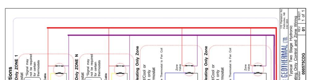
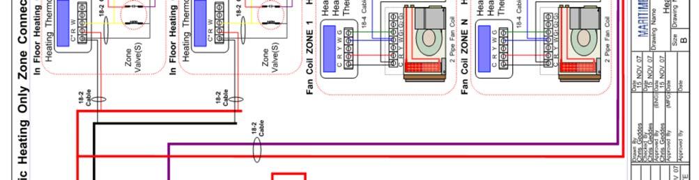
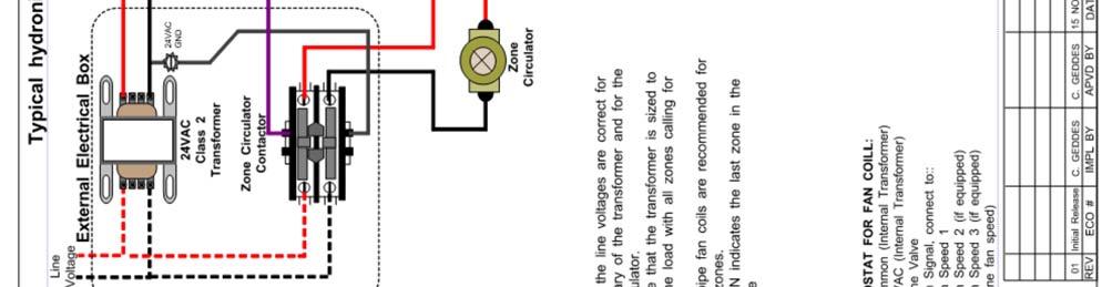
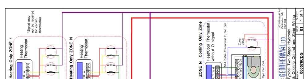
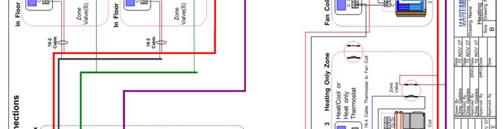
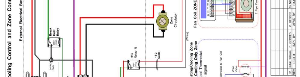
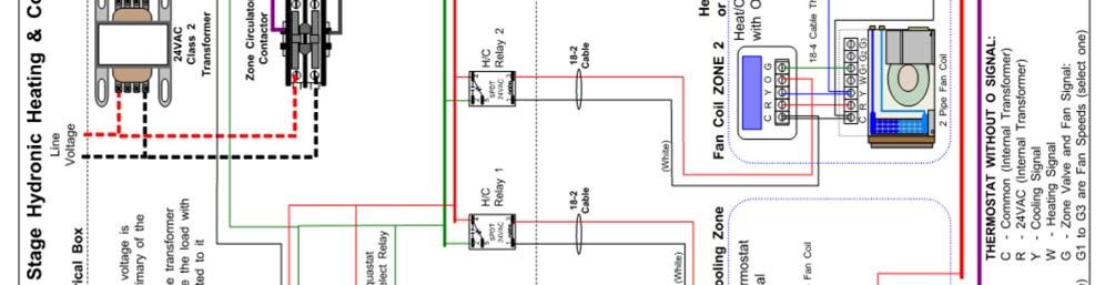
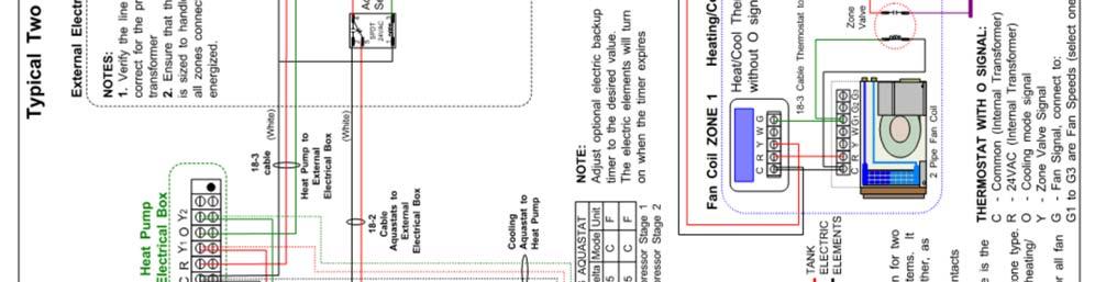
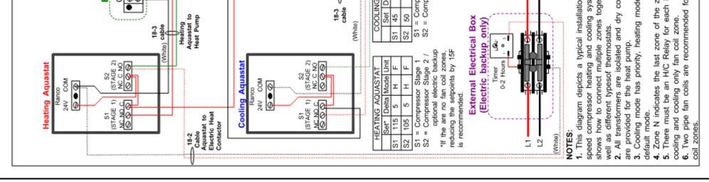
7 CONTROL REQUIREMENTS Two stage models require a two-stage heating (and two stage cooling for reversing units) control system for proper operation. The stages are S1 = Stage 1 compressor, and S2 = Stage 2 compressor. Two-stage aquastats can be purchased with the unit, or other system controllers with dry contacts may be used. This manual covers operation of the heat pump with aquastats. The electrical box diagram on the electrical box cover provides a description of the signal connections in the heat pump. They are also listed in TABLE 2 below. TABLE 2 - Control Signal Description Signal Description C 24VAC Common (Ground) R 24VAC Hot Y 1 Heat Pump Stage 1 O Cooling Mode (reversing valve) Heat Pump Stage 2 (if applicable to model) Y 2 NOTE: A few models are not available in two-stage (see Electrical Tables). The Y2 signal is not used for these units. The aquastat(s) can be placed anywhere within the range of the probe cable. The probe(s) should be inserted into a dry well in or near the top of the tank for optimal operation (refer to drawing PDG). If a dry well is not available, it may be possible to fix the probe to the tank inside the insulation. The aquastat connections and system wiring differ for heating only and heating/cooling systems. Heating only systems only require one aquastat, while heating/cooling system require two, one for heating and one for cooling. Heating/ cooling systems require extra relays to provide an isolated cooling signal to the heat pump and to disable radiant in-floor heating zones while in cooling mode. Drawing CDG shows a typical wiring diagram for a heating only setup, while drawing CDG depicts a heating/ cooling wiring diagram. These drawings represent a basic system, in which heating is the default mode and cooling has priority. It is recommended that the system be designed by a qualified system designer to ensure proper functionality. TABLE 3 shows typical settings for the aquastats. With these settings, Stage 1 will activate when the tank temperature reaches the activation point. If the load is too great, the tank temperature will continue to drop when heating (rise when cooling) until Stage 2 is activated. As the tank temperature stops dropping and begins to increase when heating (decrease when cooling), Stage 2 will turn off before Stage 1, rather than at the same time as Stage 1. There are three main advantages to this: Less aquastat probe lag leading to reduced overshoot as the tank temperature rate of change is reduced when only Stage 1 is active. Prolonged Stage 1 runtime leads to increased overall efficiency as Stage 1 has a higher COP than Stage 2. Reduced number of compressor starts. TABLE 3 - Typical Aquastat Settings HEATING AQUASTAT Stage 1 Stage 2 Item F C F C Setpoint Delta Activation * COOLING AQUASTAT Stage 1 The settings may be changed as desired; however Stage 1 setpoint for heating should not exceed 120 F (49 C); Stage 1 cooling setpoint should not be set below 43 F (6 C). Exceeding these setpoint limits will cause the heat pump operating pressures to approach the safety control settings, possibly causing nuisance shut downs. NOTE: If only floor zones are being heated, it is highly recommended to drop each of the heating setpoints by 15 F (8 C) for increased efficiency. It is recommended that a buffer tank with electric elements be selected to provide auxiliary / backup heat. The tank element thermostat can be set to maximum, allowing the electric elements to be controlled by an external contactor placed in the power supply connections. The contactor can be connected to Stage 2 of the heating aquastat via a 0-2 hour timer. Refer to drawing CDG or drawing CDG. SAFETY CONTROLS Stage 2 Item F C F C Setpoint Delta Activation * *Activation is indirectly set by the Setpoint and Delta values The heat pump has two built in safety controls which are designed to protect the unit from situations which could damage it should the operation of the refrigeration circuit fall outside the allowable operating range. A. Low Pressure Control The low pressure control monitors the compressor suction pressure and will shut the compressor down if the refrigerant evaporating pressure becomes too low, risking the danger of freezing conditions in the evaporator. There are (3) main reasons why this control would activate in response to the operating conditions of the unit while operating in heating mode: 1. Low or no outdoor loop flow. 2. Low Outdoor loop entering liquid temperature. 3. Dirty or fouled Outdoor loop heat exchanger. B. High Pressure Control The high pressure safety control monitors the compressor discharge pressure and will shut the compressor down if the condensing pressure becomes too high. Page MAN-03
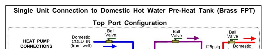
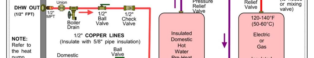
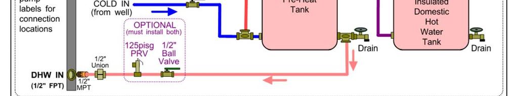
8 There are (3) main reasons why this control would activate in response to the operating conditions of the unit while operating in heating mode: 1. Low or no Indoor loop flow. 2. High Indoor loop entering liquid temperature. 3. Dirty or fouled Indoor loop heat exchanger. DOMESTIC HOT WATER CONNECTIONS (HW & HACW only) A typical piping diagram for a pre-heat tank configuration can be found in drawing PDG at the end of this section. Be sure to note the position of the check valve and the direction of water flow. Other configurations are possible, and there may be multiple units tied together in larger buildings. The unit contains a control board that monitors the safety controls and operates the compressor accordingly. Refer to APPENDIX A for control board specifications. The low pressure control is connected to LP1 and LP2. The high pressure control is connected to HP1 and HP2.! WARNING: USE ONLY COPPER LINES TO CONNECT THE DESUPERHEATER. TEMPERA- TURES COULD REACH 200F SHOULD THE DHW CUTOUT SWITCH FAIL, POTENTIALLY RUPTURING PEX PIPING. The control board also has provisions for a flow switch. The flow switch is unused from the factory and a jumper wire is placed across the FLOW SWITCH terminals. If a flow switch is desired, the jumper can be removed and the two leads from the flow switch can be connected to the FLOW SWITCH terminals on the safety board. The flow switch is ignored for 5 seconds on compressor startup to allow time for flow to be established. The high and low pressure controls are monitored at all times. The compressor will not be able to start if either of them has a fault. The control board has an on-board LED and a FAULT pin with a 24VAC output, which is routed to the L terminal of the thermostat terminal strip. An external indicator or relay can be connected across L and C on the terminal strip if external signaling is desired. Should a fault condition occur, the LED will flash the code of the fault condition while the safety control in question is open. The codes are shown in TABLE 4. The control board will lock out the compressor for five minutes when a fault occurs. The control board will then restart the compressor if the fault has been cleared. Should a second fault condition occur within a 60 minute period the control board will go into permanent lockout mode and energize the FAULT pin. The LED will flash the fault code until the control board is reset by powering down the unit.! TABLE 4 - Control Board Fault Codes Fault Code High Pressure 1 Low Pressure 2 Flow Switch (accessory) 3 WARNING: If the control board enters permanent lockout mode there is a serious problem with the system and it must be rectified if the unit is to maintain good service. Ensure the tank is filled with water and under pressure before activating the heat pump. Slightly loosen the boiler drain on the DHW Out pipe to allow air to escape from the system before the unit is started. This step will make certain that the domestic hot water circulator in the unit is flooded with water when it is started.! CAUTION: The domestic hot water pump is water lubricated; damage will occur to the pump if it is run dry for even a short period of time. Connect the brown wire with the blue insulated terminal to L1 of the compressor contactor (fuse terminal for units). Ensure the power is off when connecting the wire. The DHW loop may have to be purged of air several times before good circulation is obtained. A temperature difference between the DHW In and DHW Out can be felt by hand when the circulator pump is operating properly. For the pre-heat tank setup, the final tank should be set to 140 F(60 C), unless local code requires a higher setting. The pre-heat tank does not require electric elements. This setup takes full advantage of the desuperheater as it is the sole heat provider to the pre-heat tank. The desuperheater remains active during the compressor runtime until the pre-heat tank has been completely heated by the desuperheater alone. This setup is more energy efficient than a single tank setup.! CAUTION: If two (2) shut-off valves are located on the domestic hot water lines as shown in the diagram, a pressure relief valve must be installed to prevent possible damage to the domestic hot water circulator pump should both valves be closed.! WARNING: REPEATED RESETS OF A LOW PRES- SURE LOCKOUT COULD CAUSE THE HEAT EX- CHANGER TO FREEZE AND RUPTURE, DESTROY- ING THE HEAT PUMP & VOIDING THE WARRANTY MAN-03 Page 8
9 Page MAN-03
10 001490MAN-03 Page 10
11 Page MAN-03
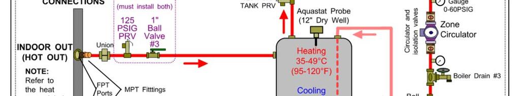
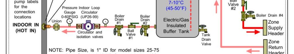
12 Sizing and Hydronics HEAT PUMP SIZING TABLE 5 depicts a rough guideline as to the size of home each heat pump size can handle for ground loop installations. TABLE 5 - Heat Pump Size vs. Heated Area for a Ground Loop System Model Size (tons) Sq.ft. Sq.m , , , , , TABLE 6 depicts a rough guideline as to the size of home each heat pump size can handle for ground water installations. TABLE 6 - Heat Pump Size vs. Heated Area for a Ground Water System Model Size (tons) Sq.ft. Sq.m , , , , , , THE TABLES ABOVE ARE FOR INFORMATION ONLY. THEY SHOULD NOT BE USED TO SELECT A UNIT SIZE. They simply show on average what size unit is required for a typical two-level home (main level and below grade basement) with R-20 walls, R-40 ceiling and average size and number of windows. The Heated Area is the area of the main level; the tables account for a basement the same size as the heated area. MARITME GEOTHERMAL LTD. HIGHLY RECOM- MENDS THAT A PROPER HEAT LOSS/GAIN ANALYSIS BE PERFORMEDE BY A PROFESSIONAL INSTALLER WITH CSA APPROVED SOFTWARE BEFORE SELECTING THE SIZE OF UNIT REQUIRED FOR THE APPLICATION. For heating dominant areas, we recommend sizing the unit to 100% of the heating design load for maximum long term efficiency with minimal supplementary heat. The unit should be installed as per CSA For ground loop applications, the ground exchanger should be designed using suitable software with a multi-year analysis. There are many factors to consider when sizing the heat pump. Some of these factors include the number of levels, the size of the windows, the orientation of the home, attached garage, bonus rooms, walk-in basement, coldest outdoor temperature, etc. The heat loss program will take all of these factors into consideration in its calculations. An undersized installation will require not be as efficient and will required expensive supplemental heat to maintain a comfortable temperature in the home, and the cost savings of having a geothermal heat pump are greatly reduced. Once the total heat loss has been calculated, the unit can be sized using the performance tables (from the specifications document) in conjunction with the minimum expected entering liquid temperature of the ground loop (well water temperature for ground water system). The heat pump output must be able to match the total heat loss at the selected entering water temperature in order to provide a comfortable environment with minimal auxiliary heat. HYDRONIC SYSTEMS - GENERAL Hydronic systems typically provide heat through two different types of media: radiant in-floor heating forced air heating via fan coil units One of the benefits of hydronic systems is the flexibility in setting up the heating system. Whereas a typical forced air system has one central thermostat controlling the entire heating system, the home may be sectioned into several areas called zones with a hydronic system. Each zone has its own thermostat, allowing simple separate temperature control of the individual areas in the home. There are other uses for hydronic systems, the two most common being on-demand domestic hot water and pool/spa heating. Drawing PDG shows the most common types of zones. A typical system consists of the heat pump, the buffer tank and the zones. The heat pump s sole purpose is to maintain the buffer tank set point. Its operation is independent of the zone operation. Drawing PDG shows a typical piping configuration for a single unit with a buffer tank. This is a guideline for a simple installation. There are many other configurations, such as separate heating and cooling buffer tanks, multiple units connected to one buffer tank, etc. It is recommended that the hydronic system be designed by a qualified system designer to ensure proper functionality. Fan coils can be used to provide heating and/or cooling for areas that do not have radiant in-floor heating. They provide a means of air heating/cooling with minimal or no ductwork. Note that the buffer tank temperature may need to be set as high as 115 F (46 C) if there are fan coils in the system. Two pipe fan coils are recommended for connection to the system if a single buffer tank is used for heating and cooling. For systems with separate hot and cold buffer tanks, two pipe fan coils are recommended for zones that provide only one function (heating or cooling), while four pipe fan coils are recommended for zones that heat and cool. These are simply suggestions, the fan coil selection will depend on the final system design. It is recommended that all piping be insulated with 3/8 thick closed cell pipe insulation. This is a MUST for any piping that is used for cooling to prevent dripping onto floors and walls. Care should be taking when wiring the system to ensure that radiant in-floor heating zones are disabled whenever the heat pump is switched to cooling mode MAN-03 Page 12
13 Page MAN-03
14 001490MAN-03 Page 14
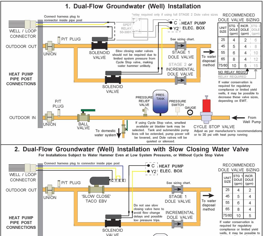
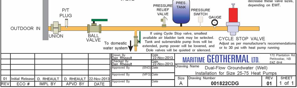
15 Ground Water Systems GENERAL REQUIREMENTS 1. The temperature of the well water should be a minimum of 41 F (5 C), and should normally be 45+ F (7 C) 2. The well system must be able to supply the required water flow as listed under the Total Flow column in TABLE 7. TABLE 7 - Required Flow and Air Tank Sizing Heat Pump Model Size Heat Pump Flow* USGPM (L/s) Home Flow USGPM (L/s) Total Flow USGPM (L/s) Minimum Air Bladder Tank** USgal (L) (0.50) 4 (0.25) 12 (0.76) 24 (91) (0.63) 4 (0.25) 14(0.88) 28 (106) (0.76) 4 (0.25) 16(1.01) 32 (121) (0.88) 4 (0.25) 18(1.14) 36 (136) (1.01) 4 (0.25) 20 (1.26) 40 (151) (1.07) 4 (0.25) 21(1.32) 42 (159) * These are minimum water requirements based on an entering water temperature of 46 F. **Based on two-minute well pump run time. Use next size larger tank if there is not a match for the value indicated. A larger tank may be used if a longer run time is desired. PLUMBING THE HEAT PUMP Plumbing lines, both supply and discharge, must be of adequate size to handle the water flow necessary for the heat pump. A 1 copper or plastic line should be run to the Outdoor IN (Supply IN) pipe of the heat pump. Similarly, a 1 ' line should be run from the Outdoor OUT (Supply Out) pipe to the method of disposal. P/T plugs should be installed at each port. See DIAGRAM A in the Ground Loop section for a description of P/T plugs. The water valve should be installed in the discharge line. Refer to drawing CDG at the end of this section for the recommended setup. Placing the water valve in the discharge line ensures that the heat exchanger inside the heat pump remains full of water when the unit is not running. Unions or some other form of disconnect should be used so that the coaxial heat exchanger may be accessed should it required cleaning. The heat pump has an electrical connector for the water valve just inside the case. After the water valve is installed, run the valve harness into the case through the hole provided. Remove the jumper plug from the Valve Connector and connect the harness in its place. Water flow to the heat pump can be controlled very accurately by the installation of a reverse action refrigeration pressure valve in the discharge line of the unit. Another more common method of regulating the flow is by the use of a DOLE Valve. This valve will automatically control the amount of water flowing through it by varying the diameter of a flexible rubber orifice through which the water passes. This minimizes the water usage of the unit and also prevents a reversing unit from running excessively low discharge pressure when in cooling mode. Dole valves can be noisy, it is recommended that they be installed outside if possible. Optionally a water flow meter can be installed in the discharge line so that the exact amount of water flowing can be determined at a glance. It should be placed between the Outdoor OUT (Supply OUT) pipe of the heat pump and the water valve. With proper flow, there should be 5-7 F (3-4 C) delta T between the IN and OUT water temperatures of the heat pump when operating in the heating mode. All water line valves on both the supply and discharge lines should be either BALL or GATE valves. GLOBE valves have a higher pressure drop, meaning more pumping power to maintain the required flow to the heat pump. PIPE INSULATION All ground water piping to and from the Outdoor Loop ports on the heat pump should be insulated with 3/8 closed cell pipe insulation, to prevent condensation and dripping onto floors or walls. WATER DISCHARGE METHODS Water disposal methods vary from area to area. However, some consideration should be made to prevent the cooled discharge water from immediately coming in contact with the supply source. Attempting to return the water to the source well will eventually cool the water so much that the heat pump will shut off on its low pressure safety control. Acceptable methods for disposing of the waste water are listed below. The waste water is clean, the heat pump has no other effect than reducing the temperature of the water. Refer to drawing INF for typical disposal method diagrams. Second well (return well) Percolation (Drain, ditch, leaching field) Pond, river or stream. ENSURE SELECTED METHOD CONFORMS TO LOCAL CODES. Ideally there will be water flow available in excess of the requirement of the heat pump. In such a situation the proper pump can be selected to maintain a pressure of 30 to 40 psig. on the lines when the heat pump is operating. However in some cases a well can supply a heat pump only if the minimum requirement for water is used. Page MAN-03

 it may be necessary to place a well cap on the well to keep the return water from flowing out the top of the well.")


16 A return well should be a minimum of 80 ft. from the supply well for residential applications. The water returned to the well will not necessarily be pumped into the same aquifer, depending on underground conditions. The return must be able to supply at least the same quantity of water as the amount you wish to recharge into it. If the static level (level when not being pumped) of a well is high (10 to 20 ft. from the surface) it may be necessary to place a well cap on the well to keep the return water from flowing out the top of the well. This cap is commonly required since a certain amount of pressure is needed to force the return water back down the well if the static level is high. Water discharged by percolation will generally soak into the ground within a distance of 50 to 100 ft. If suitable care is taken to ensure that the drain pipe runs downhill and the end of the pipe is protected by a bale of hay or spruce bows etc. the end of the pipe will not freeze as the pipe will empty out when the heat pump shuts off and the water valve closes. When snow comes it will usually cover the entire process much like a small spring. It is recommended that the pipe be below the frost line when possible for maximum freeze protection. When discharging into a river or stream, or above the surface of a pond, the same guidelines should be followed as described in the paragraph above for the percolation method. When discharging the waste water below the surface of a pond, the discharge pipe should be placed below the frost line to prevent the pipe from freezing. As opposed to the percolation method, water will remain in the end of the pipe. It is recommended that the surface of the pond be lower than the installation location of the heat pump where practical. This reduces the back pressure generated by the weight of the water in the pond MAN-03 Page 16
17 Page MAN-03
18 001490MAN-03 Page 18

; the two pump module will typically handle 4 to 6 ton systems (model sizes 55, 65, 75).")
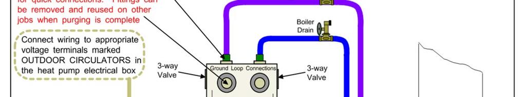
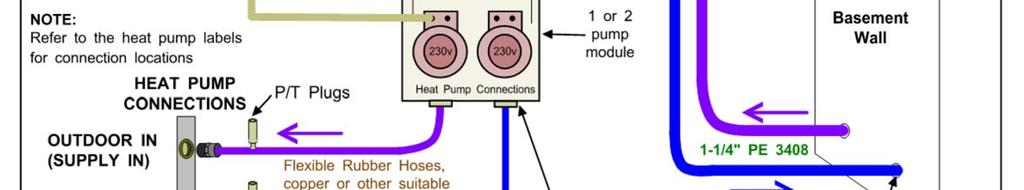
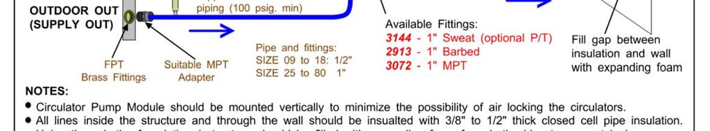
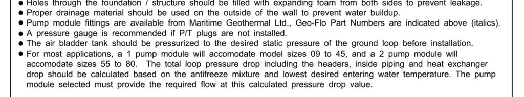
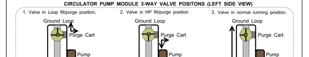
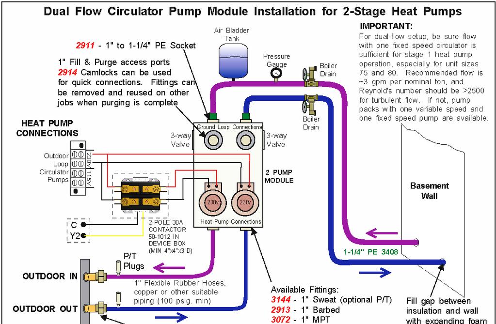
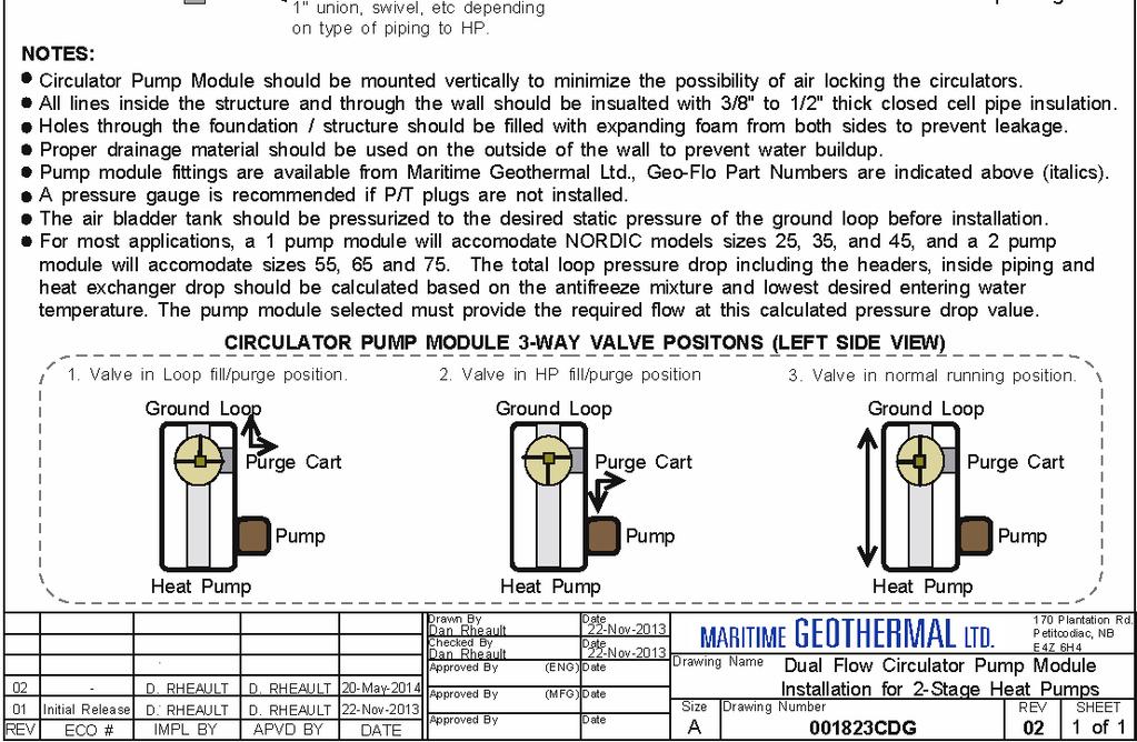
19 Ground Loop Systems Once the ground loop has been pressure tested and the header pipes have been connected to the circulator pump module, the heat pump can be connected to the circulator pump module. CIRCULATOR PUMP MODULE Maritime Geothermal Ltd. has compact pump modules with built in three way valves to facilitate filling and purging the ground loop. Refer to drawing CDG at the end of this section. Alternatively, Grundfoss Model UPS or Taco Model 0011 pumps or other brands with similar pumping capability may be used. The single pump module will typically handle systems up to 3 tons (model sizes 25-45); the two pump module will typically handle 4 to 6 ton systems (model sizes 55, 65, 75). This is based on a typical parallel system with one circuit per ton. Maritime Geothermal recommends calculating the total pressure drop of the ground loop (including headers, indoor piping and heat pump exchanger drop) based on the antifreeze type and concentration at the desired minimum loop temperature. A pump module that can deliver the flow required for the unit at the calculated total pressure drop should be selected. Refer to the Model Specific Information section for unit flow requirements. Loop pressure drops can be calculated using software such as those mentioned in the Horizontal Ground loops section, or can be calculated in a spreadsheet using the pipe manufacturer s pressure drop tables for pipe diameter and fittings. The P/T plug will allow the installer or homeowner to check water flow through the loop by measuring the pressure difference through the heat exchanger and comparing it to that listed in the Model Specific Information section, or the specifications document. Optional fittings with P/T ports are available for the circulator pump modules sold by Maritime Geothermal Ltd.. FLUSHING & PURGING THE GROUND LOOP Once the groundloop has been installed and all connections are completed between the heat pump, circulator pump module and ground loop, the entire ground loop system should be pressure tested with air to 100 PSIG to make sure there are no leaks on any of the inside fittings. Soap all joints and observe that the pressure remains constant for 1 hour. When satisfied that all connections are leak free, release the air pressure and connect a purge cart (see Diagram B) to the flushing access ports at the pump module (refer to drawing CDG). A temporary flushing system can alternately be constructed using a 45 gal. barrel and a pump with sufficient volume and head capability to circulate fluid at a velocity of at least 2 ft./min. through all parts of the loop. DIAGRAM B - Typical Purge Cart The circulator pump module must be connected to the heat pump Outdoor Loop ports with a lineset suitable for the flow required with minimum pressure drop. 1 rubber or plastic lines should be used. The installation of P/T plugs (pressure / temperature, pronounced Pete s plugs ) is recommended on both the entering and leaving lines at the heat pump (see Diagram A). DIAGRAM A - Typical P/T Pete s Plug & Thermometer Stems Adjust the circulator pump module valves to connect the purge cart to the ground loop. Begin pumping water through the ground loop, ensuring that the intake of the pump stays submerged at all times by continuously adding water. Water flowing back from the return line should be directed below the water level in the barrel or flush tank to prevent air being mixed with the outgoing water. Page MAN-03
20 Once the lines have been filled and no more air bubbles are appearing in the line, adjust the circulator pump module valves to circulate water through the heat pump using the same technique as described above. When all air is removed reverse the flow of water through the lines by interchanging the flush cart lines and purge again. You will be able to visibly tell when all air is removed. ADDING ANTIFREEZE SOLUTION In most mid and northern areas of the US and in all of Canada it is necessary to condition the loop fluid by the addition of some type of antifreeze solution so that it will not freeze during operation in the winter months. This antifreeze is required because the loop fluid will normally reach a low entering temperature of 28 F to 32 F (-2 C to 0 C) and refrigerant temperatures inside the heat pump s heat exchanger may be as low as 20 F (11 C) cooler. See TABLE 8 for details of freeze protection provided by different concentrations. TABLE 8 - Antifreeze Percentages BY VOLUME Protection to: 10 F 15 F 20 F 25 F Methanol 25% 21% 16% 10% Propylene Glycol 38% 30% 22% 15% BY WEIGHT Protection to: 10 F 15 F 20 F 25 F Methanol 16.8% 13.6% 10% 6.3% Propylene Glycol 30% 23.5% 18.3% 12.9% NOTE: Add enough antifreeze to allow for a temperature 20 F (11 C) lower than the expected lowest loop fluid temperature entering the heat pump. Although many different antifreeze solutions have been employed in geothermal systems, the alcohols such as methanol or ethanol have the most desirable characteristics for groundloop applications. The overall heat transfer characteristics of these fluids remain high although care must be taken when handling pure alcohols since they are extremely flammable. Once mixed in a typical 25% by volume ratio with water the solution is not flammable. In situations where alcohols are not allowed as a loop fluid due to local regulations then propylene glycol is a non-toxic alternative which can be substituted. Propylene glycol should only be used in cases where alcohols are not permitted since the heat transfer characteristics are less desirable and it becomes more viscous at low temperatures, increasing pumping power. The volume of fluid that your loop system holds can be closely estimated by totaling the number of ft. of each size pipe in the system and referencing TABLE 9 the for approximate volume per 100 ft. When the volume of the loop has been calculated and the appropriate amount of antifreeze is ready for addition by referencing TABLE 8, drain the equivalent amount of water from the flush cart or mixing barrel and replace it with the antifreeze. When using alcohols, be sure to inject below the water line to reduce initial volatility of the pure antifreeze. If the loop is large it may be necessary to refill the tank with antifreeze several times to get all the antifreeze into the loop. Pump the loop for 5 to 10 minutes longer to ensure the remaining fluid has been well mixed. TABLE 9 - Volume of fluid per 100 ft. of pipe Volume /100ft. Type of Pipe Diameter Igal USgal L Copper / / Rubber Hose Polyethylene 3/4 IPS SDR IPS SDR /4 IPS SDR /2 IPS SDR IPS SDR Other Item Volumes Heat Exchanger Average Purge Cart Tank See cart manual TBD INITIAL PRESSURIZATION At this point open all valves in the flow circuit and slowly close off the supply and return flush cart valves in a manner that leaves about psig. on the system. If an air bladder expansion tank is used it should be charged to the above pressure before actual water pressure is put on the system. Systems without an expansion tank will experience greater fluctuations in pressure between the heating and cooling seasons, causing pressure gauges to have different values as the loop temperature changes. This fluctuation is normal since expansion and contraction of the loop fluid must be handled by the elasticity of the plastic loop. Pressurize the loop to a static pressure of 45 psig. when installing a system in the fall going into the heating season. Pressurize the loop to a static pressure of 25 psig. when installing a system in the spring or summer going into the cooling season. After operating the heat pump for a period of time, any residual air in the system should be bled off and the static pressure should be verified and adjusted if necessary. Add additional water / antifreeze mix with the purge cart to bring the pressure back to the original setting if required. PIPE INSULATION All ground loop piping inside the structure (between the structure entry point and the heat pump) should be insulated with 3/8 thick closed cell pipe insulation to prevent condensation and dripping onto floors or walls MAN-03 Page 20

21 Page MAN-03
22 001490MAN-03 Page 22
23 Startup Procedure The following steps describe how to perform the startup procedure of the geothermal heat pump. The W-Series Two-Stage R410a Startup Record located in this manual is used in conjunction with this startup procedure to provide a detailed record of the installation. A completed copy should be left on site, a copy kept on file by the installer and a copy should be sent to Maritime Geothermal Ltd. Check the boxes or fill in the data as each step is completed. For data boxes, circle the appropriate units. Fill in the top section of all three copies, or one copy if photocopies can be made after the startup has been completed. PRE-START INSPECTION Indoor Loop (Hydronic Loop): 1. Verify that all shutoff valves are fully open and there are no restrictions in the piping from the heat pump to the indoor loop, and that full flow is available to the heat pump. 2. Verify that the entire system has been flooded and all the air has been purged as much as possible. Further purging may be required after the system has been operating for a while. 3. Verify that the loop contains the proper mix of antifreeze (if used) for the intended application. If applicable, record the type of antifreeze and the mixture value on the startup sheet, circle % Vol. or % Weight. 4. Record the static loop pressure on the startup sheet. Outdoor Loop (Ground Loop): 1. Verify that all shutoff valves are fully open and there are no restrictions in the piping from the heat pump to the ground loop, and that full flow is available to the heat pump. 2. Verify that the entire system has been flooded and all the air has been purged as much as possible. Further purging may be required after the system has been operating for a while. 3. Verify that the loop contains the proper mix of antifreeze for the intended application. Record the type of antifreeze and the mixture value on the startup sheet; circle % Vol. or % Weight. 4. Record the static loop pressure on the startup sheet. Outdoor Loop (Ground Water): 1. Verify there are no leaks in the connections to the unit. Verify the water valve is installed and properly oriented in the return line. 2. Verify that there is flow control in the return line. Domestic Hot Water (if equipped): 1. Verify that all shutoff valves are fully open and there are no restrictions in the piping from the heat pump to the domestic hot water tank. 2. Verify that the entire system has been flooded and all the air has been purged as much as possible. Further purging may be required after the system has been operating for a while. 3. Verify that the brown wire with the insulated terminal is disconnected in the electrical box. Refer to the schematic diagram for more information. Electrical: 1. Ensure the power to the unit is off. 2. Verify all high voltage connections. Ensure that there are no stray wire strands, all connections are tight and the ground wire is connected tightly to the ground connector. 3. Record the fuse / circuit breaker size and wire gauge for the heat pump. 4. Verify that the control connections to the unit are properly connected and all control signals are off, so that the unit will not start up when the power is turned on. 5. Verify that the circulator pumps are connected to the proper voltage terminals in the heat pump. Record the voltages of the circulator pumps. 6. Ensure all access panels except the one that provides access to the electrical box are in place. Page MAN-03
24 UNIT STARTUP The unit is now ready to be started. The steps below outline the procedure for starting the unit and verifying proper operation of the unit controlled by aquastats. It is recommended that safety glasses be worn during the following procedures. Preparation: 1. Remove the caps from the service ports and connect a refrigeration manifold set to the unit. 2. Turn the power on to the heat pump and set the all controls to OFF. 3. Measure the following voltages on the compressor contactor and record them on the startup sheet: L1-L2, L2-L3, L1-L3. Heating Mode: 1. Set the heating aquastat setpoints to activate Stage 1 and Stage 2. The compressor will start (allow seconds for the water valve to open for ground water systems) as well as the circulator pumps. 2. Check the refrigeration gauges. The suction and discharge pressures will depend on the loop temperatures, but they should be about PSIG and PSIG respectively for a typical start-up. 3. Monitoring the refrigeration gauges while the unit runs. Record the following after 10 minutes of runtime: 1. Suction pressure 2. Discharge pressure 3. Indoor Loop In (Hot In) temperature 4. Indoor Loop Out (Hot Out) temperature 5. Indoor Delta T (should be between 8-12 F, 4-6 C) 6. Outdoor Loop In (Supply In) temperature 7. Outdoor Loop Out (Supply Out) temperature 8. Outdoor Delta T (should be between 5-8 F, 3-4 C) 9. Outdoor flow (if available) 10. Compressor L1(C) current (black wire, place meter between electrical box and compressor) 4. Adjust the aquastat setpoint to the desired buffer tank temperature and let the unit run through a cycle. Record the setpoint and the discharge pressure when the unit shuts off. 5. For units with a desuperheater, turn the power off to the unit. Connect the brown wire with the blue insulated terminal to the compressor contactor as shown in the electrical box diagram. Turn the power to the unit on. 6. Open a zone (or zones) and let the tank cool down until Stage 2. is activated. Close the zone(s) again. 7. Verify the DHW IN and DHW OUT temperatures (if applicable) by hand (caution: pipes get hot). If the DHW OUT line does not become hotter than the DHW IN line the circulator is air locked. Bleed the air from the system and check the temperature differential again to ensure there is flow from the circulator. Cooling Mode: 1. Set the unit to cooling mode and adjust the cooling aquastat setpoints to activate Stage 1 and Stage Monitoring the refrigeration gauges while the unit runs. Record the following after 10 minutes of runtime: 1. Suction pressure 2. Discharge pressure 3. Indoor Loop In (Hot In) temperature 4. Indoor Loop Out (Hot Out) temperature 5. Indoor Delta T 6. Outdoor Loop In (Supply In) temperature 7. Outdoor Loop Out (Supply Out) temperature 8. Outdoor Delta T 3. Adjust the cooling aquastat setpoints to the desired tank temperature, and allow the unit to run through a cycle. Record the aquastat setpoint and the suction pressure when the unit shuts off. Final Inspection: 1. Turn the power off to the unit and remove all test equipment. 2. Install the electrical box cover and the access panel on the heat pump. Install the service port caps securely to prevent refrigerant loss. 3. Do a final check for leaks in the ground water / ground loop system and ensure the area is clean. 4. Turn the power on to the unit. Set the aquastats to the final settings and record the values. Startup Record: 1. The startup personnel shall sign and date the Startup Record and have the startup witness or appropriate site personnel sign as well. The startup personnel shall leave the Startup Record with the homeowner, retain a copy for filing and send a copy to Maritime Geothermal Ltd. for warranty registration MAN-03 Page 24
25 Startup Record Sheet W-Series Size Two-Stage R410a Installation Site Startup Date Installer City Company Province Check boxes unless Model Country asked to record data. Circle data units. Serial # Homeowner Name Homeowner Phone # Indoor Loop (Hydronic) Ground Loop System Ground Water System Domestic Hot Water PRE-START INSPECTION All shut-off valve are open (full flow available) Loop is full and purged of air Antifreeze type Antifreeze concentration % Volume % Weight Loop static pressure PSI kpa All shut-off valve are open (full flow available) Loop is full and purged of air Antifreeze type Antifreeze concentration % Volume % Weight Loop static pressure PSI kpa Water Valve installed in return line Flow control installed in return line All shut-off valves are open Lines are full and purged Desuperheater pump wire is disconnected Electrical High voltage connections are correct and securely fastened Circuit breaker (or fuse) size and wire gauge for Heat Pump A Ga. Circulator pump voltages (Outdoor 1, Outdoor 2, Indoor 1) V V V Low voltage connections are correct and securely fastened STARTUP DATA Preparation Voltage across L1 and L2, L1 and L3, L2 and L3 VA C Heating Mode (10 Suction Pressure / Discharge Pressure psig kpa minutes) Indoor In (Hot In), Indoor Out (Hot Out), and Delta T In Out F C Outdoor In (Supply In), Outdoor Out (Supply Out), and Delta T In Out F C Cooling Mode (10 minutes) Final Aquastat Settings Outdoor Flow Igpm USgpm L/s Compressor L1 (black wire) current Heating aquastat setpoint and discharge pressure at cycle end F C psig kpa Domestic Hot Water functioning Suction Pressure / Discharge Pressure psig kpa Indoor In (Hot In), Indoor Out (Hot Out), and Delta T In Out F C Outdoor In (Supply In), Outdoor Out (Supply Out), and Delta T In Out F C Cooling aquastat setpoint and suction pressure at cycle end F C psig kpa Heating S1 Setpoint, S1 Delta, S2 Setpoint, S2 Delta F C Cooling S1 Setpoint, S1 Delta, S2 Setpoint, S2 Delta F C Date: Startup Personnel Signature: Witness/Site Signature: A total of three copies are required, one for the site, one for the installer/startup and one to be sent to Maritime Geothermal Ltd. Page MAN-03 A
26 General Maintenance GENERAL MAINTENANCE SCHEDULE Item Interval Procedure Contactor 1 year Inspect for pitted or burned points. Replace if necessary. Heat exchanger As required* Clean as per HEAT EXHCANGER FLUSING PROCEDURE below. *Generally not required for closed loop systems. Whenever system performance is reduced for open loop. STEP 1 STEP 2 STEP 3 STEP 4 STEP 5 STEP 6 STEP 7 COAXIAL HEAT EXCHANGER FLUSHING PROCEDURE GROUNDWATER Isolate the heat exchanger by closing the valves in the IN and OUT ports to the heat exchanger. Blow out the heat exchanger into a clean 5 gallon bucket using compressed air. If a purge cart is not available, use a 5 gallon plastic bucket, a circulator and some plastic piping to create a makeshift pump system. Connect a the inlet and outlet to the heat exchanger ports.* Place 2 gallons of RYDLYME in the purge cart (or bucket). Circulate the fluid through the heat exchanger for at least 2 hours (3 recommended). Disconnect the purge system dispose of the solution. RYDLYME is non-toxic and biodegradable and as such can be poured down a drain. Connect fresh water and a drain to the heat exchanger ports and flush the exchanger for several minutes. Return the plumbing to its original configuration and open the IN and OUT valves. Operate the system and check for improved performance. *Depending on the plumbing, there should be either unions or boiler drains for to access the heat exchanger. STEP 1 STEP 2 STEP 3 COAXIAL HEAT EXCHANGER FLUSHING PROCEDURE GROUND LOOP Isolate the heat exchanger by placing the pump module valves in the exchanger flushing position. Connect a compressed air and a drain pipe to the pump module purge ports and blow the anti-freeze solution into a clean 5 gallon bucket. Connect a purge cart to the pump module purge ports. STEP 4 Place 2 gallons of RYDLYME in the purge cart. Circulate the fluid through the heat exchanger for at least 2 hours (3 recommended). STEP 5 STEP 6 STEP 7 STEP 8 STEP 9 STEP 10 Disconnect the purge cart and dispose of the solution. RYDLYME is non-toxic and biodegradable and as such can be poured down a drain. Clean the purge cart thoroughly. Connect fresh water and a drain to the pump module purge ports and flush the exchanger for several minutes. Blow the heat exchanger out with compressed air as per STEP 2 and dump the water down a drain. Connect the purge cart to the pump module purge ports. Re-fill and purge the heat exchanger with as per standard procedures (the anti-freeze from STEP 2 can be re-used). Disconnect the purge cart and set the pump module valves back to the original positions. Operate the system and check for improved performance. *Depending on the plumbing, there should be either unions or boiler drains for to access the heat exchanger MAN-03 Page 26
27 Troubleshooting Guide The following steps are for troubleshooting the geothermal heat pump. If the problem is with the domestic hot water, proceed to that section at the end of the troubleshooting guide. Repair procedures and reference refrigeration circuit diagrams can be found at the end of the troubleshooting guide. STEP 1: Verify that the display is present on the heating or cooling aquastat. If it is not present on either, proceed to POW- ER SUPPLY TROUBLE SHOOTING, otherwise proceed to STEP 2. STEP 2: Remove the door and electrical box cover and check to see if there is a fault code on the control board. If there is, record the fault code. Turn the power off, wait 10 seconds and turn the power back on. Set the appropriate aquastat for a call for heating or cooling depending on the season. STEP 3: If a 24VAC signal does not appear across Y1 and C of the terminal strip, proceed to the AQUASTAT TROUBLE SHOOTING section, otherwise proceed to STEP 4. STEP 4: If a fault code appears once a signal is present at Y1 and the compressor does not attempt to start, proceed to the FAULT CODE TROUBLESHOOTING section, otherwise proceed to STEP 5. STEP 5: If no fault codes appear and the compressor does not attempt to start, attempts to start but cannot, starts hard, or starts but does not sound normal, proceed to the COMPRESSOR TROUBLESHOOTING section, otherwise proceed to STEP 6. STEP 6: If the compressor starts and sounds normal, this means the compressor is OK and the problem lies elsewhere. Proceed to the OPERATION TROUBLESHOOTING section. NOTE: To speed up the troubleshooting process, the Test Jumper on the control board can be placed to the YES position to change the anti-short cycle timer to 5 seconds. Be sure to set it back to NO when servicing is POWER SUPPLY TROUBLESHOOTING Fault Possible Cause Verification Recommended Action No power to the heat pump Disconnect switch open (if installed) Fuse blown / Breaker Tripped. Verify disconnect switch is in the ON position. At heat pump disconnect box, voltmeter shows 230VAC on the line side but not on the load side. Determine why the disconnect switch was opened, if all is OK close the switch. Reset breaker or replace fuse with proper size and type. (Timedelay type D ) No display on either aquastat. Transformer breaker tripped. Faulty transformer Faulty wiring between heat pump and aquastats. Breaker on transformer is sticking out. Transformer breaker is not tripped, 230VAC is present across L1 and L3 of the compressor contactor but 24VAC is not present across R and C of the terminal strip. 24VAC is not present across 24V and COM at the top of the aquastat. Push breaker back in. If it trips again locate cause of short circuit and correct. Replace transformer. Correct the wiring. Faulty aquastat. 24VAC is present across 24V and COM of the aquastat but there is no display. Replace aquastat. Page MAN-03
28 AQUASTAT TROUBLESHOOTING Fault Possible Cause Verification Recommended Action No Y1 signal to heat pump Incorrect aquastat setup. Faulty aquastat to heat pump wiring. Faulty aquastat to heat pump wiring. Faulty aquastat. Aquastat does not indicate S1 on the display. 24VAC not present across Stage 1 C and COM of the aquastat. 24VAC signal present across Stage 1 NO and COM of the aquastat but not present across Y1 and C of the terminal strip. No 24VAC between Stage 1 NO and COM of the aquastat when S1 is indicated on the aquastat display. Correct the setup. Correct or replace wiring. Correct or replace wiring. Replace aquastat. Setting(s) not retained Faulty aquastat E2 error message. Can cause the unit to trip a safety control if the setting is too high or low. Replace aquastat. FAULT CODE TROUBLESHOOTING Fault Possible Cause Verification Recommended Action Fault Code 1 (High Pressure Control) Faulty High Pressure Control (open). * Must be a signal present on Y1 for this test. *HP pressures must be at static levels. Faulty control board. Verify if there is 24VAC across HP1 on the control board and C of the terminal strip, as well as HP2 and C. 24VAC is present across HP1 and C1, and HP2 and C, but no voltage is present across CC on the control board and C. Replace high pressure control if voltage is present on HP1 but not on HP2. Replace control board. Fault Code 2 (Low Pressure Control) Faulty Low pressure control (open). * Must be a signal present on Y1 for this test. *HP pressures must be at static levels. Verify if there is 24VAC across LP1 on the control board and C of the terminal strip, as well as LP2 and C. Faulty control board. 24VAC is present across LP1 and C, and LP2 and C, but no voltage is present across CC on the control board and C. Unit out of refrigerant. Check static refrigeration pressure of the unit for a very low value. Replace high pressure control if voltage is present on LP1 but not on LP1. Replace control board. Locate the leak and repair it. Spray nine, a sniffer and dye are common methods of locating a leak. Fault Code 3 (Flow Switch) Flow switch jumper removed or faulty. Verify jumper is in place between pins marked FLOW SWITCH. Place a jumper if missing. Flow switch faulty. (Only if installed) Verify 24VAC is present between each flow switch pin on the control board and the C terminal of the terminal strip while there is flow through the unit. Replace flow switch if signal is not present at both terminals on the control board. Faulty control board. 24VAC is present across each FLOW SWITCH terminal and C, but not voltage is present across CC on the control board and C. Replace control board MAN-03 Page 28
29 COMPRESSOR TROUBLESHOOTING Fault Possible Cause Verification Recommended Action Compressor will not start Faulty control board. Faulty run capacitor. (Single phase only) Loose or faulty wiring. Faulty compressor contactor. Measuring from C on the terminal strip, verify there is voltage at Y, HP1, HP2, LP1, LP2, and both flow pins but no voltage present at CC. Check value with capacitance meter. Should match label on capacitor. Compressor will hum while trying to start and then trip its overload. Check all compressor wiring, including inside compressor electrical box. Voltage on line side with contactor held closed, but no voltage on one or both terminals on the load side. Points pitted or burned. Or, 24VAC across coil but contactor will not engage. Replace control board. Replace if faulty. Fix any loose connections. Replace any damaged wires. Replace contactor. Thermal overload on compressor tripped. Burned out motor. (open winding) Burned out motor. (shorted windings) Ohmmeter shows reading when placed across R and S terminals and infinity between C & R or C & S. A valid resistance reading is present again after the compressor has cooled down. Remove wires from compressor. Ohmmeter shows infinite resistance between any two terminals Note: Be sure compressor overload has had a chance to reset. If compressor is hot this may take several hours. Remove wires from compressor. Resistance between any two terminals is below the specified value. Proceed to Operation Troubleshooting to determine the cause of the thermal overload trip. Replace the compressor. Replace the compressor. Motor shorted to ground. Remove wires from compressor. Check for infinite resistance between each terminal and ground. If any terminal to ground is not infinite replace the compressor. Seized compressor due to locked or damaged mechanism. Compressor attempts to start but trips its internal overload after a few seconds. (Run capacitor already verified) Attempt to rock compressor free. If normal operation cannot be established, replace compressor. Compressor starts hard Start capacitor faulty. (Single phase only) Check with capacitance meter. Check for black residue around blowout hole on top of capacitor. Replace if faulty. Remove black residue in electrical box if any. Potential Relay faulty. (Single phase only) Replace with new one and verify compressor starts properly. Replace if faulty. Compressor is tight due to damaged mechanism. Compressor attempts to start but trips its internal overload after a few seconds. Run capacitor has been verified already. Attempt to rock compressor free. If normal operation cannot be established, replace compressor. Compressor Stage 2 will not activate Faulty Stage 2 module. Verify if 24VAC is present across Y2 and C of the terminal strip. Replace module if signal is present. Check wiring if signal is not present. Page MAN-03
30 OPERATION TROUBLESHOOTING - HEATING MODE Fault Possible Cause Verification Recommended Action High Discharge Pressure Aquastat set too high. Verify aquastat setting Lower aquastat setting to recommended value of 115 F (46 C) Low or no Indoor loop flow. TXV adjusted too far closed. TXV stuck. Delta T across the Indoor Loop ports should be between 8-12 F (3-6 C), or compare pressure drop to the tables for the unit. Verify superheat. It should be between 8-12 F (3-6 C). Superheat will be high if TXV is closed too far. Adjusting the TXV does not affect the superheat or the suction pressure. Verify pump is working and sized correctly. Check for restrictions in the circuit, ie valve partially closed. Adjust TXV to obtain 8-12 F (3-6 C) superheat. Adjust the TXV all the way in and out a few times to loosen it. Replace TXV if this does not work. Filter-drier plugged Unit is overcharged. (Only possible if unit has been opened in the field and incorrectly charged). Feel each end of the filter- drier, it should be the same temperature. If there is a temperature difference then it is plugged. Also causes low suction pressure. High sub-cooling, low delta T across air coil. Replace filter-drier. Remove 1/2lb of refrigerant at a time and verify that the discharge pressure reduces. Low Suction Pressure Low or no Outdoor liquid flow Entering liquid temperature too cold. Dirty or fouled coaxial heat exchanger. (typically for ground water, unlikely for ground loop) Indoor Loop entering liquid temperature too cold TXV stuck almost closed or partially blocked by foreign object. Delta T across the Outdoor Loop ports should be between 5-7 F (3-4 C), or compare pressure drop to the tables for the unit. Measure the entering liquid temperature. Most likely caused by undersized ground loop. Disconnect the water lines and check the inside of the pipes for scale deposits. Measure temperature. Should be above 60 F (15 C). Adjusting the TXV does not affect the superheat or the suction pressure. TXV may be frosting up. Determine the cause of the flow restriction and correct it. Verify pumps are working and sized correctly for ground loop systems. Verify well pump and water valve is working for ground water systems. Increase the size of the ground loop. Have a qualified service technician backflush the coaxial exchanger. Restrict Indoor liquid flow temporarily until buffer tank comes up to temperature. Adjust the TXV all the way in and out a few times to loosen it. Replace TXV if this does not work. Low refrigerant charge. Faulty compressor, not pumping. Entering liquid temperature, flow and entering air temperature are good but suction is low. Check static refrigeration pressure of the unit for a very low value. Pressures change only slightly from static values when compressor is started. Locate the leak and repair it. Spray nine, a sniffer and dye are common methods of locating a leak. Replace compressor MAN-03 Page 30
31 OPERATION TROUBLESHOOTING - HEATING MODE Fault Possible Cause Verification Recommended Action High Suction Pressure (may appear to not be pumping) Compressor frosting up Leaking reversing valve. TXV adjusted too far open. TXV stuck open. See Low Suction Pressure in this section. Reversing valve is the same temperature on both ends of body, common suction line is warm, compressor is running hot. Verify superheat. It should be between 8-12 F (3-6 C). Superheat will be low if TXV is open too far. Adjusting the TXV does not affect the superheat or the suction pressure. Low super heat and discharge pressure. Replace reversing valve. Adjust TXV to obtain 8-12 F (3-6 C) superheat. Adjust the TXV all the way in and out a few times to loosen it. Replace TXV if this does not work. TXV frosting up TXV stuck almost closed or partially blocked by foreign object. Adjusting the TXV does not affect the superheat or the suction pressure. Adjust the TXV all the way in and out a few times to loosen it. Replace TXV if this does not work. Random high pressure trip (does not occur while on site) Faulty compressor contactor. Intermittent Indoor circulator. Points pitted or burned. Contactor sometimes sticks causing the compressor to run when it shouldn t, tripping the high pressure control. Verify wiring is good Replace contactor. Correct the wiring or replace the circulator. OPERATION TROUBLESHOOTING - COOLING MODE Fault Possible Cause Verification Recommended Action Heating instead of cooling Control wiring not set up properly or cooling select relays not functioning. Verify that there is 24VAC across O and C of the terminal strip when calling for cooling. Correct control wiring or replace relays. Faulty reversing valve solenoid coil. Faulty reversing valve. Verify solenoid by removing it from the shaft while the unit is running. There should be a loud whoosh sound when it is removed. A click can be heard when the coil is energized but the unit continues to heat instead of cool. Replace solenoid if faulty. Replace reversing valve. High Discharge pressure Low or no Outdoor liquid flow Entering liquid temperature too warm. Dirty or fouled coaxial heat exchanger. (typically for ground water, unlikely for ground loop) Delta T across the Outdoor Loop ports should be between 8-12 F (4-7 C), or compare pressure drop to the tables for the unit. Most likely caused by undersized ground loop. Disconnect the water lines and check the inside of the pipes for scale deposits. Determine the cause of the flow restriction and correct it. Verify pumps are working for ground loop systems. Verify well pump and water valve is working for ground water systems. Verify the ground loop sizing. Increase the size of the ground loop if undersized. Have a qualified service technician backflush the coaxial exchanger. Page MAN-03
32 OPERATION TROUBLESHOOTING - COOLING MODE Fault Possible Cause Verification Recommended Action High Discharge pressure Unit is overcharged. (Only possible if unit has been opened in the field and incorrectly charged) High sub-cooling, low delta T across water coil. Remove 1/2lb of refrigerant at a time and verify that the discharge pressure reduces. High Suction Pressure (may appear to not be pumping) TXV adjusted too far open. TXV stuck open. Verify superheat. It should be between 8-12 F (3-6 C). Superheat will be low if TXV is open too far. Adjusting the TXV does not affect the superheat or the suction pressure. Low super heat and discharge pressure. Adjust TXV to obtain 8-12 F (3-6 C) superheat. Adjust the TXV all the way in and out a few times to loosen it. Replace TXV if this does not work. Leaking reversing valve. Reversing valve is the same temperature on both ends of body, common suction line is warm, compressor is running hot. Replace reversing valve. Low Suction Pressure Aquastat set too low. Verify aquastat setting Raise aquastat setting to recommended value of 45 F (7 C) Low or no Indoor loop flow. TXV stuck almost closed or partially blocked by foreign object. Delta T across the Indoor Loop ports should be between 5-7 F (3-4 C), or compare pressure drop to the tables for the unit. Adjusting the TXV does not affect the superheat or the suction pressure. TXV may be frosting up. Verify pump is working and sized correctly. Check for restrictions in the circuit, ie valve partially closed. Adjust the TXV all the way in and out a few times to loosen it. Replace TXV if this does not work. Low or no refrigerant charge. Faulty compressor, not pumping. Entering air temperature and airflow are good but suction is low. Check static refrigeration pressure of unit for very low value. Pressures change only slightly from static values when compressor is started. Locate the leak and repair it. Spray nine, a sniffer and dye are common methods of locating a leak. Replace compressor. Compressor frosting up See Low Suction Pressure in this section. TXV frosting up TXV stuck almost closed or partially blocked by foreign object. Adjusting the TXV does not affect the superheat or the suction pressure. Adjust the TXV all the way in and out a few times to loosen it. Replace TXV if this does not work. Random Low Pressure trip (does not occur while there) Faulty compressor contactor. Points pitted or burned. Contactor sometimes sticks causing the compressor to run when it shouldn t, tripping the low pressure control. Replace contactor. Intermittent Indoor circulator. Verify wiring is good Correct the wiring or replace the circulator MAN-03 Page 32
 Visually inspect the setting. Readjust the setting to 120 F. (140 F if required by local code) Breaker tripped, or fuse blown in electrical supply to hot water tank.")
 Circulator pump not operating. Blockage or restriction in the water line or hot water heat exchanger.")
. Check contact operation. Should close at 120 F and open at 140 F.")
. Check contact operation.")
 Visually inspect the setting. Readjust the setting to 120 F.")
33 DOMESTIC HOT WATER (DHW) TROUBLE SHOOTING Fault Possible Cause Verification Recommended Action Insufficient hot water (Tank Problem) Thermostat on hot water tank set too low. Should be set at 120 F. (140 F if required by local code) Visually inspect the setting. Readjust the setting to 120 F. (140 F if required by local code) Breaker tripped, or fuse blown in electrical supply to hot water tank. Check both line and load sides of fuses. If switch is open determine why. Replace blown fuse or reset breaker. Reset button tripped on hot water tank. Check voltage at elements with multimeter. Push reset button. Insufficient hot water (Heat Pump Problem) Circulator pump not operating. Blockage or restriction in the water line or hot water heat exchanger. Visually inspect the pump to see if shaft is turning. Use an amprobe to measure current draw. Check water flow and power to pump. Check water lines for obstruction Replace if faulty. Remove obstruction in water lines. Acid treat the domestic hot water coil. Faulty DHW cutout (failed open). Check contact operation. Should close at 120 F and open at 140 F. Replace DHW cutout if faulty. Heat pump not running enough hours to make sufficient hot water. Note the amount of time the heat pump runs in any given hour. Temporarily turn up the tank thermostats until colder weather creates longer run cycles. Water is too hot. Faulty DHW cutout (failed closed). Check contact operation. Should close at 120 F and open at 140 F. Replace DHW cutout if faulty. Thermostat on hot water tank set too high. Should be set at 120 F. (140 F if required by local code) Visually inspect the setting. Readjust the setting to 120 F. (140 F if required by local code) Trouble Shooting Tools Refrigeration In-line Flowmeter Digital Multimeter - Voltmeter / Dole flow control Valve The Dole flow control is a simple, selfcleaning device designed to deliver a constant volume of water from any outlet whether the pressure is 15 psig or as high as 125 psi. The controlling mechanism consists of a flexible orifice that varies its area inversely with pressure so that a constant flow is maintained. Page MAN-03
34 REPAIR PROCEDURES STEP 1 STEP 2 STEP 3 STEP 4 STEP 5 STEP 6 PUMP DOWN PROCEDURE Connect the refrigerant recovery unit to the heat pump service ports via a refrigeration charging manifold and to a recovery tank as per the instructions in the recovery unit manual. If there was a compressor burn out, the refrigerant cannot be reused and must be disposed of according to local codes. All water coil heat exchangers must either have full flow or be completely drained of fluid before recovery begins. Failure to do so can freeze and rupture the heat exchanger, voiding its warranty. (Note that this does not apply to double wall domestic hot water exchangers (desuperheater coils) Ensure all hose connections are properly purged of air. Start the refrigerant recovery as per the instructions in the recovery unit manual. Allow the recovery unit suction pressure to reach a vacuum. Once achieved, close the charging manifold valves. Shut down, purge and disconnect the recovery unit as per the instructions in its manual. Ensure the recovery tank valve is closed before disconnecting the hose to it. Connect a nitrogen tank to the charging manifold and add nitrogen to the heat pump until a positive pressure of 5-10PSIG is reached. This prevents air from being sucked into the unit by the vacuum when the hoses are disconnected. The heat pump is now ready for repairs. Always ensure nitrogen is flowing through the system during any soldering procedures to prevent soot buildup inside the pipes. Maritime Geothermal Ltd. recommends replacing the liquid line filter-drier anytime the refrigeration system has been exposed to the atmosphere. STEP 1 STEP 2 STEP 3 STEP 4 STEP 5 VACUUM AND CHARGING PROCEDURE After completion of repairs and nitrogen pressure testing, the refrigeration circuit is ready for vacuuming. Release the refrigerant circuit pressure and connect the vacuum pump to the charging manifold. Start the vacuum pump and open the charging manifold valves. Vacuum until the vacuum gauge remains at less than 500 microns for at least 1 minute with the vacuum pump valve closed. Close the charging manifold valves then shut off and disconnect the vacuum pump. Place a refrigerant tank with the proper refrigerant on a scale and connect it to the charging manifold. Purge the hose to the tank. Weigh in the appropriate amount of refrigerant through the low pressure (suction) service port. Refer to the label on the unit or TABLE 9 - Refrigerant Charge Chart for the proper charge amount. If the unit will not accept the entire charge, the remainder can be added through the low pressure service port after the unit has been restarted. STEP 1 STEP 2 STEP 3 STEP 4 STEP 5 STEP 6 STEP 7 REPLACMENT PROCEDURE FOR A COMPRESSOR BURN-OUT Pump down the unit as per the Pump Down Procedure above. Replace the compressor. Replace the liquid line filter-drier. Vacuum the unit until it remains under 500 microns for several minutes with the vacuum pump valve closed. Charge the unit and operate it for continuously for 2 hours. Pump down the unit and replace the filter-drier. Vacuum the unit until it remains under 500 microns for several minutes with the vacuum pump valve closed. Charge the unit (refrigerant can be re-used) and operate it for 2-3 days. Pump down the unit and replace the filter-drier. Charge the unit (refrigerant can be re-used) and operate it for 2 weeks. Pump down the unit and replace the filter-drier. Charge the unit a final time. Unit should now be clean and repeated future burn-outs can be avoided MAN-03 Page 34
35 Model Specific Information This section provides general information particular to each model. For complete specifications please see the specifications document for the desired model. REFRIGERANT CHARGE CHART Table 10 - Refrigerant - R410a SIZE Lbs. kg System contains POE oil. SHIPPING INFORMATION Table 11 - Shipping Information MODEL WEIGHT DIMENSIONS in (cm) Lbs. (kg) L W H (138) 34 (86) 34 (86) 35 (89) (150) 34 (86) 34 (86) 35 (89) (177) 34 (86) 34 (86) 35 (89) (222) 45 (114) 37 (94) 37 (94) (245) 45 (114) 37 (94) 37 (94) (268) 45 (114) 37 (94) 37 (94) Table 12 - Standard Capacity Ratings - Ground Loop Heating* 60Hz EWT 104 F (40 C) STAGE 1 - ELT 41 F (5 C) STAGE 2 - ELT 32 F (0 C) Model Liquid Flow Outdoor Input Mode (Outdoor & Indoor) Pressure Drop Energy Capacity COP H USGPM L/s PSI kpa Watts BTU/Hr kw W/W Stage 1 1,290 14, Stage 2 1,635 17,300 5, Stage 1 1,760 19, Stage 2 2,455 26, Stage 1 2,740 29, Stage 2 3,270 34, Stage 1 3,120 34, Stage 2 4,025 42, Stage 1 3,765 41, Stage 2 4,630 49, Stage 1 5,860 58, * 15% NaCl by Weight Ground Loop Fluid EWT 104 F (40 C) STANDARD STADARD CAPACITY RATINGS TABLES RATINGS The The tables tables below below depict depict the the results results of of standard capacity capacity rating rating tests tests according to C to C , standards. which is C identical to is ISO identical to Stage ISO values do NOTE: not apply Some to single stage models units. are Refer only to available the Electrical as single Tables stage to at determine the present which time. models Stage are 1 data single in stage. the following tables does not apply to these units. Table 13 - Standard Capacity Ratings - Ground Water Heating 60Hz ELT 50 F (10 C) Model Liquid Flow Outdoor Input Mode (Outdoor & Indoor) Pressure Drop Energy Capacity COP H USGPM L/s PSI kpa Watts BTU/Hr kw W/W Stage 1 1,300 16, Stage 2 1,740 22, Stage 1 1,855 22, Stage 2 2,455 32, Stage 1 2,475 32, Stage 2 3,565 45, Stage 1 3,200 39, Stage 2 4,345 54, Stage 1 3,785 47, Stage 2 4,845 64, Stage 1 6,095 77, Page MAN-03
36 STANDARD CAPACITY RATINGS - continued EWT 53.6 F (12 C) Model Table 14 - Standard Capacity Ratings - Ground Loop Cooling* Liquid Flow (Outdoor & Indoor) Outdoor Pressure Drop Mode Input Energy Capacity 60Hz STAGE 1 - ELT 68 F (20 C) STAGE 2 - ELT 77 F (25 C) COP C USGPM L/s PSI kpa Watts BTU/Hr kw W/W Stage , Stage 2 1,305 21, Stage 1 1,205 23, Stage 2 2,125 31, Stage 1 1,615 31, Stage 2 2,685 40, Stage 1 1,975 39, Stage 2 3,305 49, Stage 1 2,535 45, Stage 2 3,750 55, Stage 1 4,460 66, * 15% NaCl by Weight Ground Loop Fluid EER BTUHr/W EWT 53.6 F (12 C) Table 15 - Standard Capacity Ratings - Ground Water Cooling 60Hz ELT 59 F (15 C) Model Liquid Flow Outdoor Input Mode (Outdoor & Indoor) Pressure Drop Energy Capacity COP C USGPM L/s PSI kpa Watts BTU/Hr kw W/W Stage , Stage 2 1,105 23, Stage , Stage 2 1,665 34, Stage 1 1,370 33, Stage 2 2,180 44, Stage 1 1,755 41, Stage 2 2,710 54, Stage 1 2,120 49, Stage 2 3,105 62, Stage 1 3,725 73, EER BTUHr/W NOTE: All model sizes are Energy Star rated except for size MAN-03 Page 36
37 Heating Mode (Full Load) W-25-HACW-P-1T Nominal 2 ton R410a 60 Hz Source Data (Outdoor Loop) Power Consumption Sink Data (Indoor Loop) ELT Evap. Cond. Net Flow LLT Delta T HAB Total Effective COPh EWT Flow LWT Delta T Temp Temp. Output F F USGPM F F BTU/Hr Watts Amps Watts W/W F F USGPM F F BTU/Hr C C L/s C C Watts C C L/s C C Watts ,551 1, , , , , ,713 1, , , , , ,049 1, , , , , ,379 1, , , , , ,172 1, , , , , ,705 1, , , , , ,457 1, , , , , ,180 1, , , , ,929 W-25-HACW-P-1T Source Data (Indoor Loop) CAPACITY RATINGS Compressor: ZPS20K5E-PFV Cooling Mode (Full Load) R410a 60 Hz Sink Data (Outdoor Loop) Power Consumption ELT Evap. Efficiency Temp. Cond. Flow LLT Delta T HAB Total Effective ELT Temp Flow LLT Delta T Rejection F F USGPM F F BTU/Hr Watts Amps Watts EER F F USGPM F F BTU/Hr C C L/s C C Watts COPc C C L/s C C Watts , , , , , , , , , ,122 1, , , , , ,834 1, , , , , ,229 1, , , , , ,901 1, , , , , ,545 1, , , , , ,161 1, , , , ,275 Compressor: ZPS20K5E-PFV Page MAN-03
38 CAPACITY RATINGS - continued Heating Mode (Full Load) W-45-HACW-P-1T Nominal 3 ton R410a 60 Hz Source Data (Outdoor Loop) Power Consumption Sink Data (Indoor Loop) ELT Evap. Cond. Net Flow LLT Delta T HAB Total Effective COPh EWT Flow LWT Delta T Temp Temp. Output F F USGPM F F BTU/Hr Watts Amps Watts W/W F F USGPM F F BTU/Hr C C L/s C C Watts C C L/s C C Watts ,693 2, , , , , ,499 2, , , , , ,590 2, , , , , ,692 2, , , , , ,472 2, , , , , ,502 2, , , , , ,469 2, , , , , ,629 2, , , , ,103 W-45-HACW-P-1T Source Data (Indoor Loop) Compressor: ZPS30K5E-PFV Cooling Mode (Full Load) R410a 60 Hz Sink Data (Outdoor Loop) Power Consumption ELT Evap. Efficiency Temp. Cond. Flow LLT Delta T HAB Total Effective ELT Temp Flow LLT Delta T Rejection F F USGPM F F BTU/Hr Watts Amps Watts EER F F USGPM F F BTU/Hr C C L/s C C Watts COPc C C L/s C C Watts ,366 1, , , , , ,860 1, , , , , ,355 1, , , , , ,375 1, , , , , ,427 1, , , , , ,903 1, , , , , ,354 1, , , , , ,774 2, , , , ,093 Compressor: ZPS30K5E-PFV MAN-03 Page 38
39 Heating Mode (Full Load) W-55-HACW-P-1T Nominal 4 ton R410a 60 Hz Source Data (Outdoor Loop) Power Consumption Sink Data (Indoor Loop) ELT Evap. Cond. Net Flow LLT Delta T HAB Total Effective COPh EWT Flow LWT Delta T Temp Temp. Output F F USGPM F F BTU/Hr Watts Amps Watts W/W F F USGPM F F BTU/Hr C C L/s C C Watts C C L/s C C Watts ,563 3, , , , , ,153 3, , , , , ,909 3, , , , , ,544 3, , , , , ,313 3, , , , , ,509 3, , , , , ,950 3, , , , , ,393 3, , , , ,656 W-55-HACW-P-1T Source Data (Indoor Loop) CAPACITY RATINGS - continued Compressor: ZPS40K5E-PFV Cooling Mode (Full Load) R410a 60 Hz Sink Data (Outdoor Loop) Power Consumption ELT Evap. Efficiency Temp. Cond. Flow LLT Delta T HAB Total Effective ELT Temp Flow LLT Delta T Rejection F F USGPM F F BTU/Hr Watts Amps Watts EER F F USGPM F F BTU/Hr C C L/s C C Watts COPc C C L/s C C Watts ,286 1, , , , , ,602 1, , , , , ,860 2, , , , , ,594 2, , , , , ,315 2, , , , , ,036 2, , , , , ,816 2, , , , , ,487 2, , , , ,063 Compressor: ZPS40K5E-PFV Page MAN-03
40 Heating Mode (Full Load) W-65-HACW-P-1T Nominal 5 ton R410a 60 Hz Source Data (Outdoor Loop) Power Consumption Sink Data (Indoor Loop) ELT Evap. Cond. Net Flow LLT Delta T HAB Total Effective COPh EWT Flow LWT Delta T Temp Temp. Output F F USGPM F F BTU/Hr Watts Amps Watts W/W F F USGPM F F BTU/Hr C C L/s C C Watts C C L/s C C Watts ,095 3, , , , , ,300 3, , , , , ,263 3, , , , , ,681 3, , , , , ,816 4, , , , , ,936 4, , , , , ,952 4, , , , , ,540 4, , , , ,654 W-65-HACW-P-1T Source Data (Indoor Loop) CAPACITY RATINGS - continued Compressor: ZPS51K5E-PFV Cooling Mode (Full Load) R410a 60 Hz Sink Data (Outdoor Loop) Power Consumption ELT Evap. Efficiency Temp. Cond. Flow LLT Delta T HAB Total Effective ELT Temp Flow LLT Delta T Rejection F F USGPM F F BTU/Hr Watts Amps Watts EER F F USGPM F F BTU/Hr C C L/s C C Watts COPc C C L/s C C Watts ,340 2, , , , , ,108 2, , , , , ,838 2, , , , , ,293 2, , , , , ,781 2, , , , , ,165 3, , , , , ,621 3, , , , , ,251 3, , , , ,256 Compressor: ZPS51K5E-PFV MAN-03 Page 40
41 CAPACITY RATINGS - continued Heating Mode (Full Load) W-75-HACW-P-1T Nominal 6 ton R410a 60 Hz Source Data (Outdoor Loop) Power Consumption Sink Data (Indoor Loop) ELT Evap. Cond. Net Flow LLT Delta T HAB Total Effective COPh EWT Flow LWT Delta T Temp Temp. Output F F USGPM F F BTU/Hr Watts Amps Watts W/W F F USGPM F F BTU/Hr C C L/s C C Watts C C L/s C C Watts ,577 4, , , , , ,106 4, , , , , ,549 4, , , , , ,744 4, , , , , ,409 4, , , , , ,266 4, , , , , ,104 4, , , , , ,671 4, , , , ,830 W-75-HACW-P-1T Source Data (Indoor Loop) Compressor: ZPS60K5E-PFV Cooling Mode (Full Load) R410a 60 Hz Sink Data (Outdoor Loop) Power Consumption ELT Evap. Efficiency Temp. Cond. Flow LLT Delta T HAB Total Effective ELT Temp Flow LLT Delta T Rejection F F USGPM F F BTU/Hr Watts Amps Watts EER F F USGPM F F BTU/Hr C C L/s C C Watts COPc C C L/s C C Watts ,550 2, , , , , ,721 2, , , , , ,462 3, , , , , ,355 3, , , , , ,526 3, , , , , ,825 3, , , , , ,105 3, , , , , ,428 4, , , , ,222 Compressor: ZPS60K5E-PFV Page MAN-03
42 CAPACITY RATINGS - continued Heating Mode W-80-HACW-P-1S Nominal 6 ton R410a 60 Hz Source Data (Outdoor Loop) Power Consumption Sink Data (Indoor Loop) ELT Evap. Cond. Net Flow LLT Delta T HAB Total Effective COPh EWT Flow LWT Delta T Temp Temp. Output F F USGPM F F BTU/Hr Watts Amps Watts W/W F F USGPM F F BTU/Hr C C L/s C C Watts C C L/s C C Watts ,067 5, , , , , ,322 5, , , , , ,746 5, , , , , ,774 5, , , , , ,814 5, , , , , ,881 5, , , , , ,859 6, , , , , ,755 6, , , , ,156 W-80-HACW-P-1S Source Data (Indoor Loop) Compressor: ZP70KWE-PFV Cooling Mode R410a 60 Hz Sink Data (Outdoor Loop) Power Consumption ELT Evap. Efficiency Temp. tion Cond. Flow LLT Delta T HAB Total Effective ELT Flow LLT Delta T Rejec- Temp F F USGPM F F BTU/Hr Watts Amps Watts EER F F USGPM F F BTU/Hr C C L/s C C Watts COPc C C L/s C C Watts ,484 3, , , , , ,161 3, , , , , ,642 3, , , , , ,929 3, , , , , ,881 3, , , , , ,803 4, , , , , ,065 4, , , , , ,356 4, , , , ,193 Compressor: ZP70KWE-PFV MAN-03 Page 42
43 ELECTRICAL TABLES Table 16 - Heat Pump Electrical Information (208/ ) Model Compressor In/Outdoor Circulators FLA MCA Max Fuse/ Breaker Wire Size** RLA LRA Max A Amps Amps Amps ga # # # # #6-2 80* #6-2 * Single Stage unit ** Three (3) wire required if connecting 115VAC circulators to the unit. Table 17- Heat Pump Electrical Information ( ) Model Compressor In/Outdoor Circulators FLA MCA Max Fuse/ Breaker Wire Size** RLA LRA Max A Amps Amps Amps ga # # # # #8-3 80* #8-3 * Single Stage unit ** Four (4) wire required if connecting 115VAC circulators to the unit. Table 18 - Heat Pump Electrical Information ( ) Model Compressor In/Outdoor Circulators FLA MCA Max Fuse/ Breaker Wire Size RLA LRA Max A Amps Amps Amps ga N/A # N/A # N/A # N/A # N/A # * N/A #12-3 * Single Stage unit Table 20 - Heat Pump Electrical Information ( ) Model Compressor In/Outdoor Circulators FLA MCA Max Fuse/ Breaker Wire Size RLA LRA Max A Amps Amps Amps ga # # # #8-2 75* # * Single Stage unit Table 19 - Heat Pump Electrical Information ( ) Model Compressor In/Outdoor Circulators FLA MCA Max Fuse/ Breaker Wire Size RLA LRA Max A Amps Amps Amps ga N/A # N/A # N/A # N/A # * N/A #12-3 * Single Stage unit Table 21 - Heat Pump Electrical Information ( ) Model Compressor In/Outdoor Circulators FLA MCA Max Fuse/ Breaker Wire Size RLA LRA Max A Amps Amps Amps ga # # # # # * #10-4 * Single Stage unit Page MAN-03
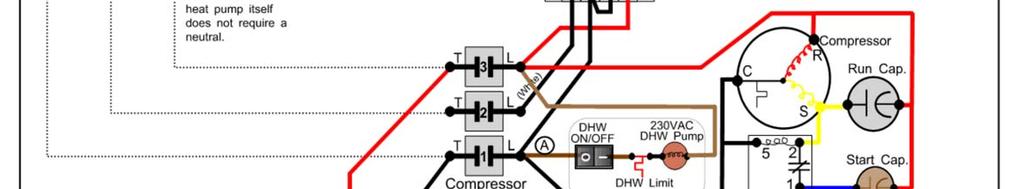
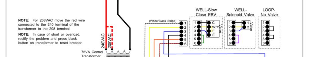
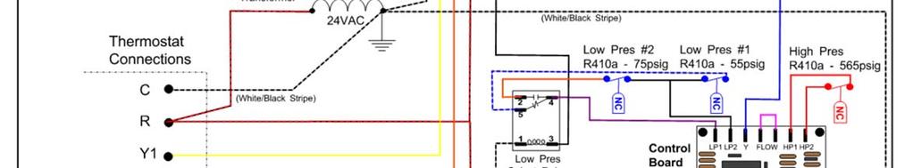
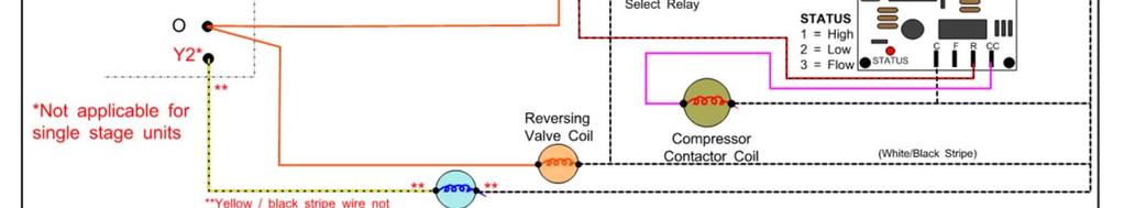
44 001490MAN-03 Page 44
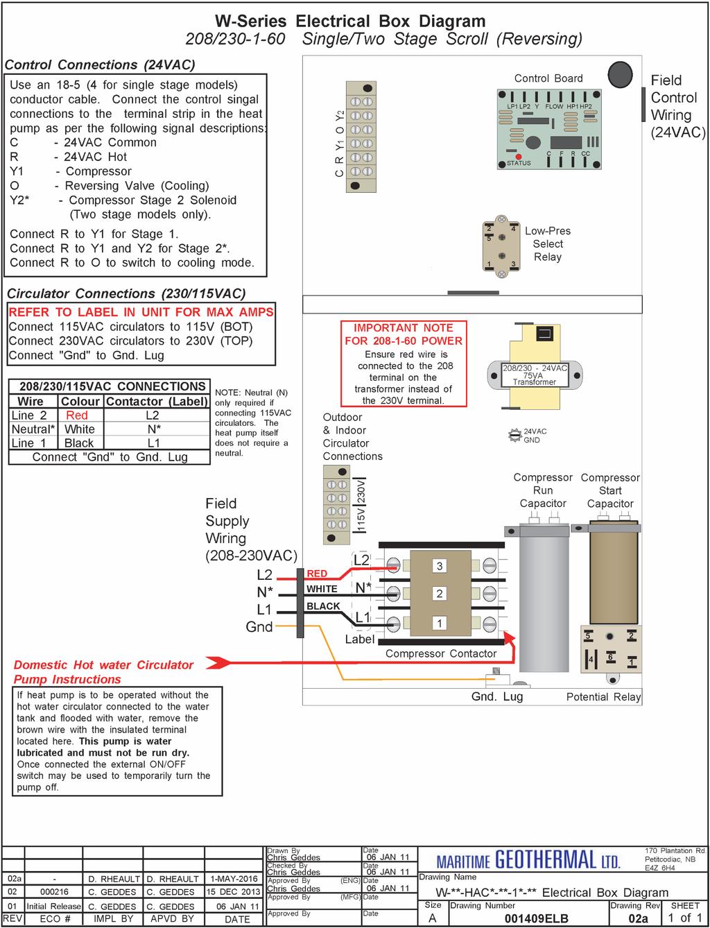
45 Page MAN-03
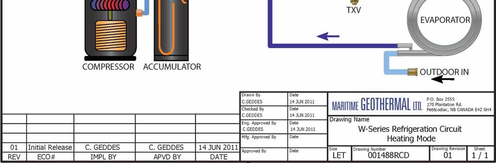
46 001490MAN-03 Page 46
47 Page MAN-03


48 DIMENSIONS Model Sizes 25 to 55 DIMENSIONS Model Sizes 65 to MAN-03 Page 48


49 APPENDIX A - Control Board Specifications Page MAN-03
50 THIS PAGE INTENTIONALLY LEFT BLANK MAN-03 Page 50
51 THIS PAGE INTENTIONALLY LEFT BLANK Page MAN-03
 or its representatives, relating to MG s products, whether oral, written or contained in any sales literature, catalogue or agreement, are")

52 LIMITED EXPRESS WARRANTY It is expressly understood that unless a statement is specifically identified as a warranty, statements made by Maritime Geothermal Ltd., a corporation registered in New Brunswick, Canada, ( MG ) or its representatives, relating to MG s products, whether oral, written or contained in any sales literature, catalogue or agreement, are not express warranties and do not form a part of the basis of the bargain, but are merely MG s opinion or commendation of MG s products. EXCEPT AS SPECIFICALLY SET FORTH HEREIN, THERE IS NO EXPRESS WARRANTY AS TO ANY OF MG S PRODUCTS. MG MAKES NO WARRANTY AGAINST LATENT DEFECTS. MG MAKES NO WARRANTY OF MERCHANTABILITY OF THE GOODS OR OF THE FITNESS OF THE GOODS FOR ANY PARTICULAR PURPOSE. LIMITED EXPRESS RESIDENTIAL WARRANTY - PARTS MG warrants its Residential Class products, purchased and retained in the United States of America and Canada, to be free from defects in material and workmanship under normal use and maintenance as follows: (1) Air conditioning, heating and/or heat pump units built or sold by MG ( MG Units ) for five (5) years from the Warranty Inception Date (as defined below). (2) Thermostats, auxiliary electric heaters and geothermal pumping modules built or sold by MG, when installed with MG Units, for five (5) years from the Warranty Inception Date (as defined below). (3) Sealed refrigerant circuit components of MG Units (which components only include the compressor, refrigerant to air/water heat exchangers, reversing valve body and refrigerant metering device) for ten (10) years from the Warranty Inception Date (as defined below). (4) Other accessories and parts built or sold by MG, when installed and purchased with MG Units, for five (5) years from the date of shipment from MG. (5) Other accessories, when purchased separately, for (1) year from the date of shipment from MG. The Warranty Inception Date shall be the date of original unit installation, as per the date on the installation Startup Record or six (6) months from date of unit shipment from MG, whichever comes first. To make a claim under this warranty, parts must be returned to MG in Petitcodiac, New Brunswick, freight prepaid, no later than ninety (90) days after the date of the failure of the part. If MG determines the part to be defective and within MG s Limited Express Residential Warranty, MG shall, when such part has been either replaced or repaired, return such to a factory recognized distributor, dealer or service organization, freight prepaid. The warranty on any part repaired or replaced under warranty expires at the end of the original warranty period. LIMITED EXPRESS RESIDENTIAL WARRANTY - LABOUR This Limited Express Residential Labour Warranty shall cover the labour incurred by MG authorized service personnel in connection with the installation of a new or repaired warranty part that is covered by this Limited Express Residential Warranty only to the extent specifically set forth in the current labour allowance schedule "A" provided by MG s Warranty Department and only as follows: (1) MG Units for two (2) years from the Warranty Inception Date. (2) Thermostats, auxiliary electric heaters and geothermal pump modules built or sold by MG, when installed with MG Units, for two (2) years from the Warranty Inception Date. (3) Sealed refrigerant circuit components of MG Units (which components only include the compressor, refrigerant to air/water heat exchangers, reversing valve body and refrigerant metering device) for five (5) years from the Warranty Inception Date. Labour costs are not covered by this Limited Express Residential Warranty to the extent they exceed the amount allowed under said allowance schedule, they are not specifically provided for in said allowance schedule, they are not the result of work performed by MG authorized service personnel, they are incurred in connection with a part not covered by this Limited Express Residential Warranty, or they are incurred more than the time periods set forth in this paragraph after the Warranty Inception Date. This warranty does not cover and does not apply to: (1) Air filters, fuses, refrigerant, fluids, oil. (2) Products relocated after initial installation. (3) Any portion or component of any system that is not supplied by MG, regardless of the cause of the failure of such portion or component. (4) Products on which the unit identification tags or labels have been removed or defaced. (5) Products on which payment to MG, or to the owner s seller or installing contractor, is in default. (6) Products subjected to improper or inadequate installation, maintenance, repair, wiring or voltage conditions. (7) Products subjected to accident, misuse, negligence, abuse, fire, flood, lightning, unauthorized alteration, misapplication, contaminated or corrosive liquid or air supply, operation at abnormal air or liquid temperatures or flow rates, or opening of the refrigerant circuit by unqualified personnel. (8) Mold, fungus or bacteria damage (9) Corrosion or abrasion of the product. (10) Products supplied by others. (11) Products which have been operated in a manner contrary to MG s printed instructions. (12) Products which have insufficient performance as a result of improper system design or improper application, installation, or use of MG s products. (13) Electricity or fuel, or any increases or unrealized savings in same, for any reason whatsoever. Except for the limited labour allowance coverage set forth above, MG is not responsible for: (1) The costs of fluids, refrigerant or system components supplied by others, or associated labour to repair or replace the same, which is incurred as a result of a defective part covered by MG s Limited Residential Warranty. (2) The costs of labour, refrigerant, materials or service incurred in diagnosis and removal of the defective part, or in obtaining and replacing the new or repaired part. (3) Transportation costs of the defective part from the installation site to MG, or of the return of that part if not covered by MG s Limited Express Residential Warranty. (4) The costs of normal maintenance. This Limited Express Residential Warranty applies to MG Residential Class products manufactured on or after February 15, MG S LIABILITY UNDER THE TERMS OF THIS LIMITED WARRANTY SHALL APPLY ONLY TO THE MG UNITS REGISTERED WITH MG THAT BEARS THE MODEL AND SERIAL NUMBERS STATED ON THE INSTALLATION START UP RECORD, AND MG SHALL NOT, IN ANY EVENT, BE LIABLE UNDER THE TERMS OF THIS LIMITED WARRANTY UNLESS THIS INSTALLATION START UP RECORD HAS BEEN ENDORSED BY OWNER & DEALER/INSTALLER AND RECIEVED BY MG LIMITED WITHIN 90 DAYS OF START UP. Limitation: This Limited Express Residential Warranty is given in lieu of all other warranties. If, not withstanding the disclaimers contained herein, it is determined that other warranties exist, any such express warranty, including without imitation any express warranties or any implied warranties of fitness for particular purpose and merchantability, shall be limited to the duration of the Limited Express Residential Warranty. LIMITATION OF REMEDIES In the event of a breach of the Limited Express Residential Warranty, MG will only be obligated at MG s option to repair the failed part or unit, or to furnish a new or rebuilt part or unit in exchange for the part or unit which has failed. If after written notice to MG s factory in Petitcodiac, New Brunswick of each defect, mal-function or other failure, and a reasonable number of attempts by MG to correct the defect, malfunction or other failure, and the remedy fails of its essential purpose, MG shall refund the purchase price paid to MG in exchange for the return of the sold good(s). Said refund shall be the maximum liability of MG. THIS REMEDY IS THE SOLE AND EXCLUSIVE REMEDY OF THE BUYER OR PURCHASER AGAINST MG FOR BREACH OF CONTRACT, FOR THE BREACH OF ANY WARRANTY OR FOR MG S NEGLIGENCE OR IN STRICT LIABILITY. LIMITATION OF LIABILITY MG shall have no liability for any damages if MG s performance is delayed for any reason or is prevented to any extent by any event such as, but not limited to: any war, civil unrest, government restrictions or restraints, strikes, or work stoppages, fire, flood, accident, shortages of transportation, fuel, material, or labour, acts of God or any other reason beyond the sole control of MG. MG EXPRESSLY DISCLAIMS AND EXCLUDES ANY LIABILITY FOR CONSEQUENTIAL OR INCIDENTAL DAMAGE IN CONTRACT, FOR BREACH OF ANY EXPRESS OR IMPLIED WARRANTY, OR IN TORT, WHETHER FOR MG s NEGLIGENCE OR AS STRICT LIABILITY. OBTAINING WARRANTY PERFORMANCE Normally, the dealer or service organization who installed the products will provide warranty performance for the owner. Should the installer be unavailable, contact any MG recognized distributor, dealer or service organization. If assistance is required in obtaining warranty performance, write or call: Maritime Geothermal Ltd Customer Service PO Box 2555 Petitcodiac, New Brunswick E4Z 6H4 (506) or to info@nordicghp.com NOTE: Some states or Canadian provinces do not allow limitations on how long an implied warranty lasts, or the limitation or exclusions of consequential or incidental damages, so the foregoing exclusions and limitations may not apply to you. This warranty gives you specific legal rights, and you may also have other rights which vary from state to state and from Canadian province to Canadian province. Please refer to the MG Installation, Installation and Service Manual for operating and maintenance instructions MAN-03 Page 52
Installation and Service Manual. Hydronic Geothermal Heat Pumps
 Installation and Service Manual Boreal W-Series (HW) Model Size 100 (9 Ton) R410a Hydronic Geothermal Heat Pumps Boreal Geothermal Inc. Phone : 450-534-0203 Fax : 450-534-1864 Email: info@boreal-geothermal.com
Installation and Service Manual
 Installation and Service Manual RS-Series Modular Design Split System Compressor Unit Two-Stage R410a Model Sizes 25-75 Liquid to Air Split System Compressor Unit Maritime Geothermal Ltd. P.O. Box 2555
Installation and Service Manual
 Installation and Service Manual TF-Series Triple Function Geothermal Heat Pump (Gen2) Two-stage R410a Model Sizes 45-80 Maritime Geothermal Ltd. P.O. Box 2555, 170 Plantation Road Petitcodiac, NB E4Z 6H4
Installation and Service Manual
 Installation and Service Manual WD-Series Wall Mounted Domestic Hot Water Water-Source Heat Pump R134a 60Hz Maritime Geothermal Ltd. P.O. Box 2555, 170 Plantation Road Petitcodiac, NB E4Z 6H4 (506) 756-8135
Installation and Service Manual
 Installation and Service Manual ATW-Series Reversing Air to Water Heat Pump Two-Stage R410a Model Sizes 25-75 Maritime Geothermal Ltd. P.O. Box 2555, 170 Plantation Road Petitcodiac, NB E4Z 6H4 (506) 756-8135
Installation and Service Manual. In-Floor Warming Module external desuperheater for 3rd party air source heat pumps
 Installation and Service Manual IFM-Series In-Floor Warming Module Model Size 48 In-Floor Warming Module external desuperheater for 3rd party air source heat pumps Maritime Geothermal Ltd. P.O. Box 2555
Installation and Service Manual. Heat Recovery Pool Conditioners
 Installation and Service Manual PC-Series Scroll R410a Model Sizes 45-80 Heat Recovery Pool Conditioners Maritime Geothermal Ltd. P.O. Box 2555 Petitcodiac, N.B. E4Z 6H4 Ph. (506)756-8135 Email: info@nordicghp.com
ENGINEERING SPECIFICATIONS
 ENGINEERING SPECIFICATIONS RH-24-HAC-P-1L-C-SDE*F Horizontal Single Stage R410a Model Size 24 Reversing (Heating AND Cooling) 208/230-1-60VAC Liquid to Air Geothermal Heat Pumps Maritime Geothermal Ltd.
ENGINEERING SPECIFICATIONS
 ENGINEERING SPECIFICATIONS RH-12-HAC-P-1L-C-SDE*F Horizontal Single Stage R410a Model Size 12 Reversing (Heating AND Cooling) 208/230-1-60VAC Liquid to Air Geothermal Heat Pumps Maritime Geothermal Ltd.
ENGINEERING SPECIFICATIONS
 ENGINEERING SPECIFICATIONS W-75-HACW-P-1T-** Liquid to Water Geothermal Heat Pump Two-Stage R410a 208/230-1-60 Maritime Geothermal Ltd. P.O. Box 2555 Petitcodiac, NB E4Z 6H4 (506)756-8135 Email: info@nordicghp.com
Installation & Operation Manual Models: TSU
 TSU-I-O Rev A Installation & Operation Manual Models: TSU 150-940 CAUTION: This appliance is not intended for potable water. This manual must only be used by a qualified heating installer / service technician.
PRE-ASSEMBLED RADIANT CONTROL PANEL INSTALLATION MANUAL
 FloorHeat PRE-ASSEMBLED RADIANT CONTROL PANEL INSTALLATION MANUAL Thank you for purchasing this radiant control panel assembly. Following are some important notes that will make the installation successful.
HPS Controls Ltd. Series 600 LFI / CFI Series 700 HFS Zone Control Stations. Heating and Radiant Floor Zone Control Stations
 Series 600 LFI / CFI Series 700 HFS Zone Control Stations Heating and Radiant Floor Zone Control Stations Installation Instructions Thank you for purchasing the finest in heating and radiant floor Control
Installation, Operating, and Maintenance Manual
 www.geo-flo.com Engineered Solutions Making Geothermal Easier Installation, Operating, and Maintenance Manual Part # 3619 Rev. 27APR2017 Geo-Booster Geo-Flo Products Corporation 905 Williams Park Drive
EarthLinked HC Series Compressor Unit R-410A Quik-Start Instructions
 EarthLinked HC Series Compressor Unit R-410A Quik-Start Instructions CONTENTS PAGE Pre-Installation 3 Placement & Mechanical Information 4 System Application Options 11 Antifreeze Protection 14 Electrical
ECO1ZN3P, ECO2ZN4P ECO
 WARNING HOT This product may have hot fluid circulating through it. DO NOT TOUCH! SOME UNION NUTS MAY BECOME LOOSE AND CONSEQUENTLY LEAK THROUGH TRANSPORTATION VIBRATION AND HANDLING. DO NOT OVERTIGHTEN
EarthLinked SW Series Compressor Unit R-410A Quik-Start Instructions
 EarthLinked SW Series Compressor Unit R-410A Quik-Start Instructions CONTENTS PAGE Pre-Installation 3 Placement & Mechanical Information 4 System Application Options 10 Antifreeze Protection 14 Electrical
Engineering Specification
 Engineering Specification W-75-HACW-P-1T-** Liquid to Water Geothermal Heat Pump 60 Hz Maritime Geothermal Ltd. P.O. Box 2555, 170 Plantation Road Petitcodiac, NB E4Z 6H4 (506) 756-8135 info@nordicghp.com
Engineering Specification
 Engineering Specification W-55-HACW-P-1T-** Liquid to Water Geothermal Heat Pump 60 Hz Maritime Geothermal Ltd. P.O. Box 2555, 170 Plantation Road Petitcodiac, NB E4Z 6H4 (506) 756-8135 info@nordicghp.com
Engineering Specification
 Engineering Specification W-25-HACW-P-1T-** Liquid to Water Geothermal Heat Pump 60 Hz Maritime Geothermal Ltd. P.O. Box 2555, 170 Plantation Road Petitcodiac, NB E4Z 6H4 (506) 756-8135 info@nordicghp.com
OWNER S MANUAL. Vintage Signature Series models: AC750, AC1050, AC1100, AC1250, AC1500, AC1750. Proudly Made in the USA.
 OWNER S MANUAL Vintage Signature Series models: AC750, AC1050, AC1100, AC1250, AC1500, AC1750 Proudly Made in the USA support@aquacomfort.com 888-475-7443 Manufacturing High Quality, High Efficiency Heat
Condensing Unit Installation and Operating Instructions
 Bulletin WCU_O&I 01 June 2003 Condensing Unit Installation and Operating Instructions WCU Air Cooled Condensing Unit Table of Contents Section 1. Section 2. Section 3. Section 4. Section 5. Section 6.
ENGINEERING SPECIFICATIONS
 ENGINEERING SPECIFICATIONS W-150-H-P-*D-PP Vertical Dual Refrigeration Circuit Scroll Compressors R410a Refrigerant Nominal Size 12 Ton Non-Reversing (Heating OR Cooling) Commercial Hydronic Geothermal
Installation and Operation Manual
 Installation and Operation Manual WT MODELS WATER-TO-WATER HEAT PUMPS REVISION C 20D218-09NN 20D218-09NN Section 1: WT Water-To-Water Unit Model Nomenclature Unit Model Nomenclature... 3 Section 2: Installation
EarthLinked SCW Series Compressor Unit R-410A Quik-Start Instructions
 EarthLinked SCW Series Compressor Unit R-410A Quik-Start Instructions CONTENTS PAGE Pre-Installation 3 Placement & Mechanical Information 6 System Application Options 12 Antifreeze Protection 13 Electrical
prestige Control Application Supplement - TriMax
 prestige Control Application Supplement - TriMax L I S T E D WARNING This document is intended to be used by a factory trained and qualified heating contractor or service technician only. Read all instructions
INSTALLATION MANUAL GEO-BOOST GROUND LOOP HEAT EXCHANGER
 1103 N HIGH CROSS RD URBANA, IL 61802 1-773-492-1893 INSTALLATION MANUAL GEO-BOOST GROUND LOOP HEAT EXCHANGER REV 1.0 The Geo-Boost system consists of the Geo-Boost heat exchanger and a relay controller
HPS Controls Ltd. Series 600 LFI / CFI Series 700 HFS Zone Control Stations. Heating and Radiant Floor Zone Control Stations
 Series 600 LFI / CFI Series 700 HFS Zone Control Stations Heating and Radiant Floor Zone Control Stations Installation Instructions Thank you for purchasing the finest in heating and radiant floor Control
WMHP Series R410a Heat Pump INSTALLATION INSTRUCTIONS
 WMHP Series R410a Heat Pump INSTALLATION INSTRUCTIONS **WARNING TO INSTALLER, SERVICE PERSONNEL AND OWNER** Altering the product or replacing parts with non authorized factory parts voids all warranty
OWNER S MANUAL. Vintage Classic HEAT COOL models. Proudly Made in the USA
 OWNER S MANUAL Vintage Classic HEAT COOL models Proudly Made in the USA support@aquacomfort.com www.aquacomfort.com/service-and-support 888-475-7443 Manufacturing High Quality, High Efficiency Heat Pump
1025, BOUL. MARCEL-LAURIN INSTRUCTION MANUAL FOR WATER COOLED ENVIROCHILL CHILLER. Prepared par Claude Gadoury, P. Eng MTL TECHNOLOGIES INC.
 WYETH-AYERST CANADA INC. 1025, BOUL. MARCEL-LAURIN S T - L A U R E N T, Q U É B E C INSTRUCTION MANUAL FOR WATER COOLED ENVIROCHILL CHILLER MODEL P448800LT--55WC--22C66S Prepared par Claude Gadoury, P.
Heat Transfer Products, Inc. 120 Braley Road East Freetown, MA The first totally integrated multiple boiler management control.
 Heat Transfer Products, Inc. 120 Braley Road East Freetown, MA 02717 The first totally integrated multiple boiler management control. USING THIS MANUAL USING THIS MANUAL A. INSTALLATION SEQUENCE Follow
water to water heat pumps
 AQUARIUS WW SERIES water to water heat pumps O ur Aquarius WW Series water-cooled modular reverse cycle chillers are designed to meet all your replacement or new construction chiller requirements. Specifically
INSTALLATION MANUAL GEO-BOOST GROUND LOOP HEAT EXCHANGER
 INSTALLATION MANUAL GEO-BOOST GROUND LOOP HEAT EXCHANGER Build Equinox support@buildequinox.com (773)-492-1893 Rev 2.0-05/10/2018 Build Equinox 2018 The Geo-Boost system consists of the Geo-Boost heat
INSTALLATION INSTRUCTIONS GEO PRIME TANK. (Patent Pending) GPC
 GPC") INSTALLATION INSTRUCTIONS GEO PRIME TANK (Patent Pending) GPC Table of Contents General Description 2 Installation 3 Flushing and Purging 5 Initial Start up 7 Adding or Checking Fluid 8 Replacing a Pump
INSTALLATION INSTRUCTIONS GEO PRIME TANK (Patent Pending) GPC Table of Contents General Description 2 Installation 3 Flushing and Purging 5 Initial Start up 7 Adding or Checking Fluid 8 Replacing a Pump
Installation & Operation Manual Forced Air
 Installation & Operation Manual Forced Air Installation & Operation Manual Engineering Specifications ECONAR ColdClimate Series Forced Air Models REC-V036 REC-V060 Table of Contents I. Key & Legend...
CROWN. Boiler Co. Santa-Fe Series. Hydronic Air Handlers INSTALLATION, OPERATION & MAINTENANCE INSTRUCTIONS
 CROWN Boiler Co Santa-Fe Series Hydronic Air Handlers INSTALLATION, OPERATION & MAINTENANCE INSTRUCTIONS These instructions must be affixed on or adjacent to the air handler Models: SAC049A20 SAC059A25
AMERICAN EQUIPMENT SYSTEMS A Division Of Trevor-Martin Corporation th Terrace North Clearwater, Florida 33762
 AMERICAN EQUIPMENT SYSTEMS A Division Of Trevor-Martin Corporation 4151 112 th Terrace North Clearwater, Florida 33762 COMMERCIAL REFRIGERANT DESUPERHEATER WASTE HEAT RECOVERY INSTALLATION/OPERATION/MAINTENANCE
AHWG Remote Mount Hot Water Generator Module for TTP Series Outdoor Split Unit
 A Remote Mount Hot Water Generator Module for TTP Series Outdoor Split Unit Installation, Operation & Maintenance Instructions 97B0080N01 B Table of Contents Model Nomenclature Example 3 Description and
3 TON Heating Performance Data TON Cooling Performance Data TON Heating Performance Data TON Cooling Performance Data...
 Table of Contents I. Key & Legend... 4 Key to Model Numbers... 4 Legend for Tables... 4 II. Warnings & Cautions... 5 III. General Information... 5 Inspection... 5 Storage 5 Protection... 5 Pre- Installation
PS SERIES PARALLEL RACK SYSTEM GLYCOL CHILLER START UP GUIDE. Master Rack Compressor Sequencer 7/21/2017
 PS SERIES PARALLEL RACK SYSTEM GLYCOL CHILLER START UP GUIDE Master Rack Compressor Sequencer 7/21/2017 1 2 Contents INTRODUCTION... 4 WARNING LABELS AND SAFETY INSTRUCTIONS... 5 PARALLEL RACK NOMENCLATURE...
Combo Geothermal Heat Pump
 Combo Geothermal Heat Pump Installation & Operating Instructions Model: RU-VE* Application Geo source, loop or ground water fluid Forced air vertical cabinet output Standard left ducting return, easily
CHILLER. Operator s & Installation Manual
 CHILLER MODELS: CH1001-A Operator s & Installation Manual Release Date: August 9, 2002 Publication Number: 620914301 Revision Date: May 6, 2010 Revision: E Visit the IMI Cornelius web site at www.cornelius.com
GTIP60 ISO GT Series, Inch Pounds - 60 Hz GT (iso) Spec Guide Drawings Spec Sheets Low Temp Heating P/T Charts
 Spec Guide Drawings Spec Sheets Low Temp Heating P/T Charts") GTIP60 ISO GT Series, Inch Pounds 60 Hz GT010070 (iso) Spec Guide Drawings Spec Sheets Low Temp Heating P/T Charts Rev: 903 Rev 1 Revisions: 31103 Changed HZ dwg to field convertible 5902 changed Unit
GTIP60 ISO GT Series, Inch Pounds 60 Hz GT010070 (iso) Spec Guide Drawings Spec Sheets Low Temp Heating P/T Charts Rev: 903 Rev 1 Revisions: 31103 Changed HZ dwg to field convertible 5902 changed Unit
EarthLinked CC Series Compressor Unit R-410A Quik-Start Instructions
 EarthLinked CC Series Compressor Unit R-410A Quik-Start Instructions CONTENTS PAGE Pre-Installation 3 Placement & Mechanical Information 4 System Application Options 11 Desuperheater Kit 15 Anti-Freeze
AHWG Remote Mount Hot Water Generator Module
 A Remote Mount Hot Water Generator Module For GT-PE (50YPS) Series Outdoor Split Unit Installation, Operation & Maintenance Instructions 97B0080N02 B Model Nomenclature Example 3 Description and Installation
OWNER S MANUAL. Models: AC110, AC125, AC150 made from 2003 through Proudly Made in the USA
 OWNER S MANUAL Models: AC110, AC125, AC150 made from 2003 through 2010 Proudly Made in the USA support@aquacomfort.com www.aquacomfort.com/service-and-support/ (888) 475-7443 Manufacturing High Quality,
INSTALLATION & MAINTENANCE MANUAL FOR QuickDraw
 INSTALLATION & MAINTENANCE MANUAL FOR QuickDraw SEMI-INSTANTANEOUS ENERGY: STEAM TO WATER U-TUBE SINGLE-WALL & DOUBLE-WALL HEAT EXCHANGERS FLOOR DRAIN Typical Construction Figure 34-1 FLOOR DRAIN 1. U-tube
Water to Water Geothermal Heat Pump
 Water to Water Geothermal Heat Pump Installation & Operating Instructions Model: THA/THT-*** Application Geo source closed loop or ground water Hydronic water heat/cool output Air handler, water coil,
4201 Lien Rd Madison, WI Owner s Manual Therma-Stor III Heat Recovery System. Installation, Operation & Service Instructions
 4201 Lien Rd Madison, WI 53704 TS-140F Revised 09-10 Owner s Manual Therma-Stor III Heat Recovery System Installation, Operation & Service Instructions Read and Save These Instructions Table Of Contents
Product Instructions. Hydronic Mixing Block Version Wiring Terminal Block Pressure/Temperature Sensor Delivery Fitting (3) Display Screen
 Display Screen") Hydronic Mixing Block Version 1.104 The Hydronic Mixing Block is a mixing device and boiler control, with a built in circulator and system controller. The block can provide either a fixed or reset water
Hydronic Mixing Block Version 1.104 The Hydronic Mixing Block is a mixing device and boiler control, with a built in circulator and system controller. The block can provide either a fixed or reset water
B. Unit construction shall comply with ASHRAE 15 Safety Code, NEC, and ASME applicable codes (U.S.A. codes).
.") Guide Specifications PART 1 GENERAL 1.01 SYSTEM DESCRIPTION Microprocessor controlled, air-cooled liquid chiller utilizing scroll compressors, low sound fans, hydronic pump system and optional fluid storage
Guide Specifications PART 1 GENERAL 1.01 SYSTEM DESCRIPTION Microprocessor controlled, air-cooled liquid chiller utilizing scroll compressors, low sound fans, hydronic pump system and optional fluid storage
Daikin Water Cooling, Heating, and High Capacity Booster Coils
 Installation and Maintenance Manual IM 900 Daikin Water Cooling, Heating, and High Capacity Booster Coils Group: Applied Air Part Number: IM 900 Date: February 2008 Types HI-F5, E-F5 2008 Daikin International
prestige Control Application Supplement - TriMax
 prestige Control Application Supplement - TriMax L I S T E D WARNING This document is intended to be used by a factory trained and qualified heating contractor or service technician only. Read all instructions
Installation & Operation Manual Hydronic
 Installation & Operation Manual Hydronic Installation & Operation Manual Engineering Specifications GeoSource Hydronic Models RGS-W036 RGS-W120 This Page Intentionally Left Blank Table of Contents I. Key
Owner s Manual Therma-Stor II Heat Recovery System
 PO Box 8680 Madison, WI 53708 TS-138C Revised 8/08 Owner s Manual Therma-Stor II Heat Recovery System Installation, Operation & Service Instructions Read and Save These Instructions Table Of Contents 1.
Engineering Specification
 Engineering Specification R-55-HACW-P-*T-*-SDE*F Liquid to Air Geothermal Heat Pump 60 Hz Maritime Geothermal Ltd. P.O. Box 2555, 170 Plantation Road Petitcodiac, NB E4Z 6H4 (506) 756-8135 info@nordicghp.com
EarthLinked SC Series Compressor Unit R-407C Quik-Start Instructions
 EarthLinked SC Series Compressor Unit R-407C Quik-Start Instructions CONTENTS PAGE Pre-Installation 3 Placement & Mechanical Information 4 System Application Options 11 Desuperheater Kit 15 Antifreeze
Engineering Specification
 Engineering Specification R-65-HACW-P-*T-*-SDE*F Liquid to Air Geothermal Heat Pump 60 Hz Maritime Geothermal Ltd. P.O. Box 2555, 170 Plantation Road Petitcodiac, NB E4Z 6H4 (506) 756-8135 info@nordicghp.com
Engineering Specification
 Engineering Specification R-55-HACW-P-*T-*-SDE*F Liquid to Air Geothermal Heat Pump 60 Hz Maritime Geothermal Ltd. P.O. Box 2555, 170 Plantation Road Petitcodiac, NB E4Z 6H4 (506) 756-8135 info@nordicghp.com
Engineering Specification
 Engineering Specification WC-55-H-C-*D-** High Temperature Cascade Water to Water Heat Pump 60 Hz Maritime Geothermal Ltd. P.O. Box 2555, 170 Plantation Road Petitcodiac, NB E4Z 6H4 (506) 756-8135 info@nordicghp.com
Bulletin (Jan 2011) And User s Guide
 And User s Guide") Bulletin 30 32 (Jan 2011) Unichiller Installation And User s Guide Customer Service If you have questions about Installation, operation and Maintenance of the Unichiller or would like to order replacement
Bulletin 30 32 (Jan 2011) Unichiller Installation And User s Guide Customer Service If you have questions about Installation, operation and Maintenance of the Unichiller or would like to order replacement
Engineering Specification
 Engineering Specification ATW-25-HACW-P-*T-* Air to Water Heat Pump 60 Hz Maritime Geothermal Ltd. P.O. Box 2555, 170 Plantation Road Petitcodiac, NB E4Z 6H4 (506) 756-8135 info@nordicghp.com www.nordicghp.com
DOUBLE O-RING GEO-PRIME TANK Non-Pressurized Flow Center System INSTALLATION INSTRUCTIONS. Model: DORGPT-1 NOTE:
 INSTALLATION INSTRUCTIONS DOUBLE O-RING GEO-PRIME TANK Non-Pressurized Flow Center System Model: DORGPT-1 NOTE: This guide provides the installer with instructions specific to the Bard Double O-Ring Geo-Prime
HPS Controls Ltd. Series 100 LTV / CTV Zone Control Stations. Heating and Radiant Floor Zone Control Stations. Installation Instructions
 Series 100 LTV / CTV Zone Control Stations Heating and Radiant Floor Zone Control Stations Installation Instructions Thank you for purchasing the finest in heating and radiant floor Control Stations. We
Installation, Operation & Service Manual
 Installation, Operation & Service Manual WARNING Improper installation, adjustment, alteration, service or maintenance can result in death, injury or property damage. Read the Installation, Operation and
G Series. G Series Air Coils Installation ti Manual ENCASED/UNCASED AIR COILS. Geothermal/Water Source Heat Pumps R-410A Refrigerant 2-5 Ton
 G Series ENCASED/UNCASED AIR COILS Geothermal/Water Source Heat Pumps R-410A Refrigerant 2- Ton Dimensional Data G Series Air Coils Installation ti Manual Installation Information Maintenance IM1018AG1
CH250 AND CH251 CHILLERS
 CH250 AND CH251 CHILLERS Operator s & Installation Manual Release Date: April 19, 2004 Publication Number: 620914801 Revision Date: May 15, 2015 Revision: G Visit the Cornelius web site at www.cornelius.com
Engineering Specification
 Engineering Specification WH-85-H-B-*S-PD High Temperature Water to DHW Heat Pump 60 Hz Maritime Geothermal Ltd. P.O. Box 2555, 170 Plantation Road Petitcodiac, NB E4Z 6H4 (506) 756-8135 info@nordicghp.com
PARALLEL RACK SYSTEM INSTALLATION & OPERATIONS MANUAL With Master Rack Compressor Sequencer
 PARALLEL RACK SYSTEM INSTALLATION & OPERATIONS MANUAL With Master Rack Compressor Sequencer 5/16 Rev. A 57-02509 2 Contents INTRODUCTION... 4 WARNING LABELS AND SAFETY INSTRUCTIONS... 5 PS SERIES PARALLEL
Operation and Maintenance Manual
 Warranty Information Ritchie Engineering guarantees YELLOW JACKET products to be free of defective material and workmanship which could affect the life of the product when used for the purpose for which
RecoverX Oil-Filled Hermetic Refrigerant Recovery System. Operation and Maintenance Manual
 RecoverX Oil-Filled Hermetic Refrigerant Recovery System Operation and Maintenance Manual Table of Contents Page General Safety Instructions 2-3 System Overview 3 Operating Guide 4 Restart Procedure 4
Installation, Operation and Maintenance Guide. Steam Coil Installation, Operation and Maintenance. steam coils
 Installation, Operation and Maintenance Guide Steam Coil Installation, Operation and Maintenance Guidelines for the installation, operation and maintenance of the Heatcraft brand of steam heating coils
Engineering Specification
 Engineering Specification WH-55-H-B-*S-** High Temperature Water to Water Heat Pump 60 Hz Maritime Geothermal Ltd. P.O. Box 2555, 170 Plantation Road Petitcodiac, NB E4Z 6H4 (506) 756-8135 info@nordicghp.com
COMPASS HIGH-EFFICIENCY WET-ROTOR CIRCULATORS
 COMPASS HIGH-EFFICIENCY WET-ROTOR CIRCULATORS INSTALLATION AND OPERATING INSTRUCTIONS File No: 10.895 Date: march 8, 014 Supersedes: 10.895 Date: december 10, 013 1.0 Symbols used in this document 1.0
GENESIS WATER-TO-WATER (GSW) SERIES. Table of Contents
 SERIES. Table of Contents") Genesis Series GSW036, 60 & 120 Water-to-Water Heat Pumps Revision: 16 Oct, 2008B GENESIS WATER-TO-WATER (GSW) SERIES Table of Contents Model Nomenclature 3 General Information 4 Physical Data 5 GSW 036
Genesis Series GSW036, 60 & 120 Water-to-Water Heat Pumps Revision: 16 Oct, 2008B GENESIS WATER-TO-WATER (GSW) SERIES Table of Contents Model Nomenclature 3 General Information 4 Physical Data 5 GSW 036
UPM I. Unit Protection Module. Installation and Operation Manual (2015/06)
") UPM I Unit Protection Module Installation and Operation Manual 6 720 220 321(2015/06) 2 Key to Symbols Contents Key To Symbols...2 Warnings...2 Specifications... 3 Unit Protection Module (UPM)....3 Power
UPM I Unit Protection Module Installation and Operation Manual 6 720 220 321(2015/06) 2 Key to Symbols Contents Key To Symbols...2 Warnings...2 Specifications... 3 Unit Protection Module (UPM)....3 Power
WILKERSON MODELS DE3, DE4 AND DE5 COMPACT HEATLESS AIR DRYERS
 INSTRUCTION MANUAL FOR WILKERSON MODELS DE3, DE4 AND DE5 COMPACT HEATLESS AIR DRYERS DE3 - DE5 OPERATIONS GENERAL This instruction manual covers the installation, operation, maintenance and troubleshooting
WP/WW SERIES. Table of Contents MODEL: WW=WATER TO WATER R-410A WP=WATER TO WATER R-22 NOMINAL CAPACITY: THOUSANDS OF BTUH - COOLING
 WP/WW SERIES Table of Contents Model Nomenclature...1 Initial Inspection...2 Installation...2 Electrical...2 Piping...3 Cooling Tower / Boiler Applications...4 Well Water Systems...4 Earth Coupled Geothermal
INSTALLATION INSTRUCTIONS TXV Horizontal Duct Coils EHD
 TXV Horizontal Duct s EHD These instructions must be read and understood completely before attempting installation. It is important that the Blower and Duct System be properly sized to allow the system
APPLICATION GUIDELINES FOR COPELAND COMPLIANT SCROLL COMPRESSORS (ZR*1 Models)
") 4-1280 Application Engineering Bulletin AE-1280R4 Revised April, 1995 APPLICATION GUIDELINES FOR COPELAND COMPLIANT SCROLL COMPRESSORS (ZR*1 Models) Introduction The Compliant Scroll Compressor has been
4-1280 Application Engineering Bulletin AE-1280R4 Revised April, 1995 APPLICATION GUIDELINES FOR COPELAND COMPLIANT SCROLL COMPRESSORS (ZR*1 Models) Introduction The Compliant Scroll Compressor has been
INSTALLATION INSTRUCTIONS WARRANTY
 QT FLOW CENTER INSTALLATION INSTRUCTIONS Fig. 1. Low Head Pump Center Flow Chart Fig. 2. High Head Pump Center Flow Chart NOTE: Read the entire instruction manual before starting the installation. WARRANTY
Condensing Unit Installation and Operating Instructions
 Bulletin ACU_O&I 02 August 2016 Condensing Unit Installation and Operating Instructions ACU Air Cooled Condensers Table of Contents Section 1. General Information... 2 Section 2. Refrigeration Piping...
Table of Contents. Installation, Operation, and Maintenance Manual ELBPxx
 Series ELBP8/ELBP30 FUSE C 4Vac R NC NO 0 min 5 Delay Off Actuator GROUND NEUTRAL LIVE Reset R CAUTION 5 VOLTS ONLY 3 4 5 6 7 8 8 Zone Wired Module 4038 Dry Contacts Pump Boiler ELBP50 GROUND NEUTRAL Reset
Single and Two-Stage Packaged Geothermal Heat Pump
 Single and Two-Stage Packaged Geothermal Heat Pump Installation & Operating Instructions Models: TVA/TVT-*** Application Forced air Geo source installation Equipped for optional AUX EL strip heat (controller
Installation instructions Danfoss heat pump DHP-R
 Installation instructions Danfoss heat pump DHP-R Table of contents DHP-R 1 Important information........................................................... 5 1.1 Refrigerant...5 1.2 Noise and vibrations...5
CAH SERIES INSTALLATION & MAINTENANCE MODELS CAH CAH
 CAH SERIES INSTALLATION & MAINTENANCE MODELS CAH 33-44-50 CAH 49-54-70 CAH VARIABLE SPEED AIR HANDLERS DIMENSIONS... 3 TECHNICAL SPECS... 4 INSTALLATION DON TS... 5 INSTALLATION DO S... 6 FREEZE STAT REQUIRED
prestige Control Application Supplement - Type 5 MCBA WARNING
 prestige Control Application Supplement - Type 5 MCBA WARNING This document is intended to be used by a factory trained and qualified heating contractor or service technician only. Read all instructions
Rev B, 9/2/2009. Kodiak Chiller Overview
 930-0001 Rev B, 9/2/2009 Kodiak Chiller Overview Presentation Outline Phone: 781-933-7300 Lytron Technical Support Contact Information 3 Introduction 4 Part I: Unpacking 5 Part II: Installation 7 Part
INSTALLATION INSTRUCTIONS
 INSTALLATION INSTRUCTIONS FOR AQUECOIL HYDRONIC HEATING UNITS GENERAL INFORMATION The AQUECOIL Hydronic Heating Unit is offered in many different capacities and physical configurations in order to match
PDF Created with deskpdf PDF Writer - Trial ::
 Instruction Manual Index Introduction Uncrating and Checking for Damage Locating Your Unit Installation Fill Tank Process Connections Pre Startup Startup Sequence Trouble Shooting Chart Operating Lights
HEATLESS DESICCANT AIR DRYER INSTRUCTION & MAINTENANCE MANUAL
 HEATLESS DESICCANT AIR DRYER INSTRUCTION & MAINTENANCE MANUAL H-Series & 203 THRU 223 SERIES ARROW PNEUMATICS, INC. REGENERATIVE DRYER DIVISION 2111 WEST 21ST STREET BROADVIEW, IL 60155 708-343-9595 708-343-1907
R.A.S.E.R.S System. Installation Guide
 R.A.S.E.R.S System Installation Guide Contents R.A.S.E.R.S System components... 1 Required components for heating, cooling, and hot water...1 Provided...1 Not provided...2 Optional components...3 R.A.S.E.R.S
95M-200. Gas-Fired Direct Vent Modulating Hot Water Boiler. Control Manual And Troubleshooting Guide. P/N , Rev.
 95M-200 Gas-Fired Direct Vent Modulating Hot Water Boiler Control Manual And Troubleshooting Guide P/N 24000604, Rev. C [04/09] WARNING! Revise boiler control parameters only if you fully understand the
DLCLRA. INSTALLATION INSTRUCTIONS Outdoor Unit Single Zone Ductless System Sizes 36 to 58 TABLE OF CONTENTS
 DLCLRA INSTALLATION INSTRUCTIONS Outdoor Unit Single Zone Ductless System Sizes 36 to 58 Fig. 1 - Size 36 TABLE OF CONTENTS PAGE SAFETY CONSIDERATIONS... 2 PARTS LIST... 3 SYSTEM REQUIREMENTS... 4 WIRING...
INSTALLATION INSTRUCTIONS TXV Horizontal Slab Coils WLSH
 TXV Horizontal Slab Coils WLSH These instructions must be read and understood completely before attempting installation. It is important that the Blower and Duct System be properly sized to allow the system
A hydronic system controls comfort by delivering heated or cooled fluid to the conditioned space through pipes.
 Introduction to Hydronics A hydronic system controls comfort by delivering heated or cooled fluid to the conditioned space through pipes. Hydronic heating systems use hot water or steam to deliver the
CHGV AIR COOLED WATER CHILLER WITH HYDRAULIC EQUIPMENT AIR / WATER 47 to 78 kw
 TECHNICAL INSTRUCTIONS CHGV AIR COOLED WATER CHILLER WITH HYDRAULIC EQUIPMENT AIR / WATER 47 to 78 kw CHGV CHGV 64 CHGV 72 CHGV 80 PHRV heat pump model also available May 2006 10 12 167 - GB - 00 MARKING
FREQUENTLY ASKED QUESTIONS
 HEAT PUMP INVERTER R-410A All-in-one, all year round heating, cooling and domestic hot water supply solution FREQUENTLY ASKED QUESTIONS WANT TO KNOW MORE? AVERAGE ANNUAL CO 2 EMISSIONS Daikin Altherma
Installation & Operations Manual
 Installation & Operations Manual HP MODELS WATER-TO-WATER HEAT PUMPS & HYDRONIC AIR HANDLERS Revision A 20D811-01NN 20D811-01NN Table of Contents Section 1: HP Unit Nomenclature HP Model Unit Nomenclature...4