User & Installer Manual SMT-400 "Enterprise" Wi-Fi Thermostat
|
|
|
- Abigail Dennis
- 5 years ago
- Views:
Transcription

1 User & Installer Manual SMT-400 "Enterprise" Wi-Fi Thermostat Ver 1.01 May 2018
2 Great care has been taken in the preparation of this manual. Smart Temp Australia P/L takes no responsibility for errors or omissions contained in this document. It is the responsibility of the user to ensure this thermostat, or the equipment connected to it is operating to their respective specifications and in a safe manner. Due to ongoing product improvement, Smart Temp Australia P/L reserves the right to change the specifications of the SMT-400 thermostat (or its components) without notice. All rights reserved. Smart Temp Australia P/L 2018 Intellectual rights apply. Manual Version History Ver1 January 2018 Initial Release - First release of the SMT-400 Manual Ver 1.01 May 2018 Small manual spelling & format corrections 2 P age
3 Contents Contents... 3 User Manual... 4 Introduction... 4 The Touch Screen - Explained... 4 Making Comfort Adjustments... 6 Turning Your SMT-400 ON or OFF... 6 Adjusting Your Set Points... 6 Adjusting Your Fan Mode & Speed... 6 Programming... 7 Using the Smart Temp Comfort App... 7 Installation Mounting the SMT-400 Thermostat Setting the Hardware Switches Typical Drawings Using Remote Temperature Sensors Attaching the Thermostat Advanced Installer Settings Control Logic Commissioning Advanced Functions Universal Input Functions V Output Functions Assignable Relay Functions ModBus Communications Outside Air Economy Cycle High and Low Balance Points High Balance Point Low Balance Point Setting Up the Heat & Cool Off Functions Belimo 6 Way Valve R30 #...#... B2 Series Supply Air Temperature Monitoring Occupancy Detection Logic Specifications Sensor Reference Table Troubleshooting P age

4 User Manual Introduction Congratulations on your purchase of the Smart Temp SMT-400 thermostat. Please take time to read and understand these simple instructions so that you may gain maximum benefit from this intuitive and powerful air conditioning control thermostat. A simple to use touch screen interface is provided that will offer you clear feedback on the comfort of your home or office and the status of your heating and air conditioning system. The SMT-400 can be used as a simple manual thermostat however when connected to your Wi-Fi network, numerous extra functions are available. Please see the section The App Explained on page 7 of this manual. Please Note: The SMT-400 thermostat can be configured by your installer to a large variety of configurations, each with specific functions so that your SMT-400 thermostat is perfect for you and your individual needs. As such, this manual may describe a function or feature not active on your thermostat. The Touch Screen - Explained Buttons A number of "buttons" or touch areas are available on the SMT-400 touchscreen. These buttons are used to adjust the heat and cool set temperature, select the heating or cooling mode or to adjust the fan speed and function. Current Room Temperature This is the temperature your SMT-400 is measuring, either with the sensor fitted directly to the SMT-400 or any remote temperature sensors wired into the SMT-400 remote temperature sensor terminals. This is the temperature your SMT- 400 will use as room temperature. Room Humidity This indicates the current level or relative humidity within the room. The SMT-400 can simply display this value or, if set by the installer, take some action to increase or decrease room humidity. Heat (or Cool) Set Temperature This part of the display shows the heat (or cool) setpoint. If the word Heat and the heat (or cool) set temperature is shown, your SMT-400 "Enterprise" is ready to heat (or cool) should the room temperature require it. If the word Heat (or Cool) in this part of the LCD is blinking, then there is a safety delay preventing the heating (or cooling) from running. This delay is up to a maximum of 4 minutes. Heat (or Cool) Set Point Adjustment Use the up or down buttons to adjust your heat (or cool) set point. 4 P age
5 Outside Air Temperature This is the current outside air temperature measured either from the hard-wired outside air sensor or from the internet for your location (if Wi-Fi is active on your SMT-400). Door / Window Open The SMT-400 has advanced energy saving functions such as door or window monitoring. (Optional door/window switch required). If enabled by the installer, when a door or window is left open for longer than a few minutes the SMT-400 will display this text and may restrict user functions until the door or window is closed. Un-Occupied Mode Indicator The SMT-400 can determine whether the room is occupied or unoccupied and alter the set points accordingly. When the room is un-occupied this text is shown to inform you the thermostat functions are locked. Set Point Limit Reached Pre-defined installer set point limits prohibit the user from apply heating set points that are too hot or cooling set points that are too cool. When the installer defined set point limit is reached the SMT-400 will chirp its beeper and flash the set point limit text on the display to indicate no further adjustment is permitted. Function Locked This Icon will be shown whenever you try and access a function or press a button that is locked out. Fault When this text is shown your SMT-400 has been provided with information from your air conditioner or building management system that a fault in the system has been detected. This may affect the function of the SMT-400 thermostat. The text Fault may be shown if your SMT-400 can connect to your wireless Wi-Fi network router however your router has lost internet access and therefore the SMT-400 cannot connect to the Smart Temp Comfort App server. Note: The text "Fault" on the SMT-400 DOES NOT indicate a fault with the SMT-400 itself. Fresh Air in Use Your SMT-400 can measure the outside air temperature and if cool enough, draw in outside air to cool your home or office. When outside air is being used this text is displayed. Communication Icon This Icon is show whenever the SMT-400 is communicating via Wi-Fi. It is shown to indicate that your SMT-400 may be receiving control information from a location other than the SMT-400 buttons. This may include set point changes, modes or other settings that affect your comfort levels. The Icon is not shown if communications are disabled or not in use. It will flash if there is a communications error or during Wi-Fi setup. Note: ModBus communications in progress is indicated by the decimal point in the room temperature flashing. Mode Adjustment Tapping this button will cycle the SMT-400 through all available modes, heating, cooling, or Auto mode. These functions are described in more below. Fan Mode Adjustment Pressing and holding this button will cycle the SMT-400 through all available fan modes being Auto Fan or Fan On mode. These functions are described in more detail below. Fan Speed Adjustment Tapping this button will cycle the SMT-400 through all available fan speeds being Low Speed, Medium Speed, High Speed or Auto Fan Speed. The SMT-400 will select the most appropriate fan speed for the current conditions. These functions are described in more detail below. 5 P age
6 Making Comfort Adjustments Turning your SMT-400 ON or OFF The mode button in the lower left of the SMT-400 changes the thermostat mode. Each tap of this button cycles the SMT- 400 through all available modes. (note, not all modes may be permitted on your SMT-400 thermostat) OFF When off is displayed your SMT-400 will not request your heating or cooling system to run. There is no active control of the room temperature. Your SMT-400 may have been configured by your installer, or via the Smart Temp Comfort App to automatically shut down if connection to the Smart Temp server is lost for more than 1 hour. (to prevent wasted energy that may occur due to your inability to remotely turn your SMT-400 off). If the SMT-400 has been shut down via this method the Text Off will flash. If you are at the SMT-400 you can simply touch the mode button to restart your heating and cooling once again. Note your SMT-400 will now continue to run until you manually select a new mode or setpoint at the thermostat or by the Smart Temp Comfort app once the server connection is restored. Heat Your SMT-400 will request your heating system to run once your room falls below your preferred heat set temperature. When Heat is shown steady your SMT-400 is ready to call for heating if needed. When Heat is flashing your SMT-400 has asked your heating system to run. E.Heat Your SMT-400 will request your Emergency heating system to automatically run once your room falls below your preferred heat set temperature or you additionally may be permitted to select E.Heat mode manually in some cases. When E.Heat is shown steady your SMT-400 is ready to call for emergency heating if needed. When E.Heat is flashing your SMT-400 has asked your emergency heating system to run. Cool Your SMT-400 will request your cooling system to run once your room raises above your preferred cool set temperature. When Cool is shown steady your SMT-400 is ready to call for cooling if needed. When Cool is flashing your SMT-400 has asked your Cooling system to run. Auto Your SMT-400 will request your Heating or Cooling system to run once your room temperature is warmer or cooler then you desire. When Heat or Cool is flashing your SMT-400 has asked your Heating or Cooling system to run. Adjusting your Set points Depending on the Mode selected as described above, the SMT-400 will show either the heat, cool or both the heat and cool set points and set point adjustment arrows. Tapping the Up or Down button will increase or decrease the set temperature by 0.5c (or 1 F) per tap. If you press and hold the up or down button for the heat or cool set point the desired temperature will move rapidly. The range of adjustment is from 5 to 50C (41 to 122F. NOTE, when in deg F mode, in the extremely unlikely event you wish to have a set point above 99F, the set Temperature display will change to show 2 large digits with a small 1 behind it. Such as 221 to indicate 122F). Please note: The SMT-400 will not permit the heating set point to be set to a higher temperature than the cooling set point. Should you attempt to adjust the heating set point above the cooling set point, or adjust the cooling set point below the heating set point the SMT-400 will push the opposing set point away. Your installer will have defined how close the heating and cooling set points can be. Adjusting your Fan mode & Speed The SMT-400 can control systems with a single Fan speed or with 3 Fan speeds. The Fan button behaves different based on how many fans speeds are being controlled. Single Speed Fan systems-. Tap this button to cycle between Continuous Fan (Fan ON) and Auto Fan. Three Speed Fan systems Tap this button to cycle between the 7 available fan modes being Low speed, Medium speed, High speed & Auto Fan speeds in Auto fan mode and then Low speed, Medium speed, High speed in Fan ON mode. 6 P age


 for the schedule to work.")


7 If the SMT-400 is OFF, tapping the FAN button will turn the fan ON or OFF as desired. If your system has 3 fan speeds these can also be selected by tapping the FAN button. Programming Although your SMT-400 is not a traditional programmable thermostat it does provide a cloud based scheduling function via the Smart Temp Comfort App. Using your app, select schedule enter your desired times and temperature settings into the app. The Smart Temp Comfort app web server will then send temperature setpoint updates to your SMT-400 Enterprise thermostats at the time scheduled. The Web Portal additionally permits you to program in holidays that will be used to control your SMT-400 Enterprise thermostat. Please note the thermostat must be set to the desired mode (Heat Cool Or Auto) for the schedule to work. Setting a scheduled cool set temperature will have no effect if your SMT-400 thermostat is in Off or Heat Only mode Using the Smart Temp Comfort App The App Explained The SMT-400 "App" will permit you to control all aspects of the wall thermostat. It will also permit you to perform many additional functions such as applying a schedule or automatically turning your home comfort system on or off as you approach or leave your home. Please refer to your App for up to date information on the functions available. Pairing your SMT-400 to Your Wi-Fi Network for the First Time Connecting your SMT-400 to the internet is a very simple process and no more difficult than connecting a lap top or other Wi-Fi device to your home or office wireless network. Step 1 Make sure your smart device is paired with the same network that you wish to pair your SMT-400 thermostat with. Example, your home Wi-Fi network if installing the SMT-400 in your home. Step 2 Download and install the "Smart Temp Comfort App" as you would any other app for your device if not previously installed. (Both Apple or Android versions available) and log into or create a new Smart Temp Comfort App account. Consult your smart device manual for help with downloading and installing apps if needed. You will need follow the prompts if setting up a new Smart Temp Comfort App account and respond to confirmation s that will be sent. Step 3 In the Smart Temp app main window, click on the + icon in the top right of the app window to add a new device. Select the Smart Wi-Fi option in the pop up box that appears. Step 4 In the Connect Window that opens, ensure the Wi-Fi network you wish to pair your SMT-400 with is shown in the Network box (this will be the same Wi-Fi network your phone is paired with. Enter the password for the shown network in the Password box. (Note -The app does not have access to your password data in the smart device, hence your need to enter this information manually) Step 5 Power up your SMT-400 Controller. After it displays the firmware version and performs a display test, the Thermostat will power up and show a typical display. The Wi-Fi symbol will flash. Simply touch the flashing Wi-Fi symbol to begin the pairing process. (The Wi-Fi symbol will time out after 2 minutes if this happen simply press and hold the display where the Wi-Fi symbol would shown for 5 seconds Just above the centre of the Mode button) 7 P age
 press the connect button on the Smart Temp Comfort App. The app will then search your paired network looking for your SMT-400.")
8 Step 6 The SMT-400 will perform a countdown from 10 to 0 as it enables, tests and resets the Wi-Fi radio within the thermostat. When the thermostat reaches 0 (zero) press the connect button on the Smart Temp Comfort App. The app will then search your paired network looking for your SMT-400. Once detected on the network the app will automatically upload the network ID and password into the SMT-400 memory. If the app fails to find your device, try the connection process again. If you have repeated failed attempts, you may need to hard reset (reboot) your smart device. Step 7 If connection is successful, your SMT-400 will display a 3-digit security code. Enter this code into the Smart Temp app in the box that has popped up. Press Enter to confirm. If you entered the correct passcode in your app the process is complete and the Smart Temp Comfort App will return to the device screen showing your SMT-400 thermostat. The Satellite icon will remain on solid confirming your connection to the building Wi-Fi router. You can now use your app from anywhere in the world that has Wi-Fi access. If you enter the incorrect passcode the SMT-400 will flash Fault. You will need re-enter your pairing code. Note On rare occasions after you pair your device the App may note advance from the connect screen, simply press connect again and re-enter enter the PIN the thermostat displayed. Adding Extra Devices to Your Account Once you have your Smart Temp "Comfort App" account setup you are free to add as many SMT-400 (and other Smart Temp Wi-Fi enabled devices) that you wish to your account. This permits you to control the SMT-400 that is installed at home, in your office or any other place that you have a Smart Temp Wi-Fi device installed and paired with the local Wi-Fi network. There are no practical limits on the number of devices you can pair to your account. Simply open the options window on your app and select "Add Device" and add the device as explained in that devices manual. Permitting Others to Control Your SMT-400 Once you have your Smart Temp "Comfort App" account set up and paired with your SMT-400 you can permit others to also have Wi-Fi control of your SMT-400. For example, a SMT-400 may be installed in a home and can then invite other family members to join in controlling the same SMT-400 thermostat. Step 1 Ensure the person you wish to add has a Smart Temp Comfort App installed on their smart device and a user account set up. Step 2 Touch the Options Window in the Smart Temp "Comfort App" and select "Add User". Step 3 Enter the account name and privilege level of the user you wish to add and press submit. This person will be sent a message on their app inviting them to share control of your thermostat. You will be sent a message informing you that the user has accepted or declined access to your SMT-400. Please Note: The SMT-400 will respond to the latest command it receives from either direct input at the thermostat or from any Wi-Fi commands. Resetting Your App Pairing If you change home or router you will need to reset your SMT-400 router pairing and set up a new connection with your new router. Step 1 If your SMT-400 fails to connect to a router stored in its memory the WiFi symbol will flash. Press the wi-fi symbol on the SMT-400 display to reset the radio back to factory settings Step 2 Follow the instructions above in Pairing you SMT-400 to the network for the First Time 8 P age
9 Wi-Fi Fault indications The Satellite symbol will flash if it cannot or is not paired with your Wi-Fi Router. Please check your Wi-Fi in your building is working and within range of the SMT-400 The satellite symbol will not be show if it has not been able to connect to your router. If after 2 minutes of power up the SMT-400 has not connected to a wi-fi router it disables the flashing wi-fi icon on the LCD (some people may not wish to use the SMT-400 Wi-fi function so the icon is disabled). If you wish to re-pair the SMT-400, simply press the location of the icon on the SMT-400 display for 5 seconds. The satellite Symbol is Shown steady, however the word Fault is flashing on the display. If the text Fault is flashing it is because your wi-fi network cannot connect to the Smart Temp server. This could be a problem with your internet service provider or an issue with the Smart Temp server. To determine if it is the Smart Temp server issue visit the server at using a web browser. Note - If the text Fault is not flashing, the SMT-400 is receiving a signal from an external device. This external device is requesting the SMT-400 to display the Text FAULT. This is NOT a fault with the SMT-400 itself 9 P age
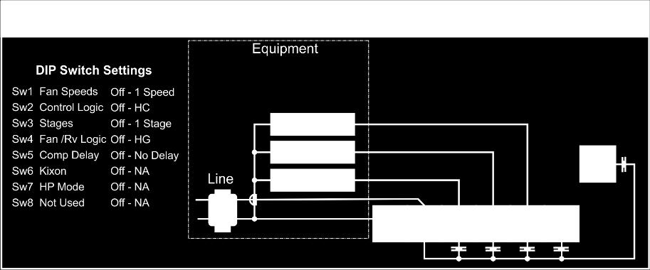
10 Installation Significant effort has been taken to make the SMT-400 thermostat system intuitive, reliable and easy to install. Using a common-sense approach to the installation will ensure this product is easily installed and to the customer s satisfaction. Please read and understand this instruction manual so that installation, testing and commissioning process is undertaken in an efficient and effective manner. As with any air conditioning project undertaken, careful installation is the key to a successful outcome. Time taken during this installation process will be rewarded with a happy customer and fewer call-backs. The steps required to install the SMT-400 thermostat are: 1. Read and understand this manual. 2. Mount the SMT-400 back plate in a suitable location. 3. Set the 8 DIP switches to match the needs of the project / user. 4. Wire the optional remote temperature sensor(s) or switches if required. 5. Power up the air conditioning system. 6. Set the installer software options (if required). 7. Test the heating, cooling, and other functions Commissioning. For convenience, the layout of this manual is in the same order as the steps listed above Mounting the SMT-400 Thermostat The SMT-400 can only be as accurate as the on-board temperature sensor or its optional remote temperature sensor(s) permits. It is therefore essential that the SMT-400 be installed in a location that is typical of the ambient room temperature. Do not install the thermostat in a draft, near a floor, behind doors or on a non-insulated external wall. Also avoid placing the thermostat in areas where the air movement is limited, affected by direct sunlight or other areas not typical of the temperature of the room. Further, when mounting the SMT-400 be aware that drafts may travel down the inside of cavity walls, (especially if mounted on external walls) and enter the back of the thermostat or sensor enclosure through the cable entry holes in the wall. It is important to fully seal these holes to prevent any drafts affecting the internally mounted temperature sensor. It is recommended to mount the SMT-400 or remote sensors between 1.5 and 1.7 metres from the floor where possible. Move the control wires through the large opening in the thermostat base plate then place the thermostat base on the wall and using appropriate screws, firmly attach the thermostat base to the wall. Block any holes where cables enter the back of the thermostat to prevent drafts entering through these holes affecting the sensor. Setting the hardware switches Switch Off On Sw1 Fan Speeds 1 Speed Fan 3 Speed Fan Sw2 Equipment Type Heat Cool Heat Pump (O/B terminals) Sw3 Stages 1 Stage 2 Stages Sw4 Reversing Valve If Sw 2= ON Heat Pump Energise in cool (O) Energise in heat (B) Sw4 Fan Mode Fan Control by Heater Fan Control by T stat (HE) If Sw 2= OFF Heat/cool (HG) Sw5 Anti Cycle Timer Off 4 Minutes Sw6 Klixon Mode Off On Sw7 Heat Pump Mode Conventional Heat Pump Fossil Fuel Mode Sw8 Not Used Typical drawings have been provided on page 11 of this manual that will assist with the selection of the correct positions for these function switches. Switch 1 Relay Assignment The SMT-400 is fitted with 5 relays capable of switching up to 1Amp. Switch 1 sets the function of these relays as either 3 fan speeds with 1 heat and 1 cool operation or single fan speed with 2 heat and 2 cool, in either HP (heat pump / reverse cycle) or HC (heat with add on cool) mode. 10 P age
 only for heating and the Y terminal(s) only for cooling. Heat Pump systems use the Y terminal(s) for BOTH heating and cooling (the compressor).")
. Switch 3 Equipment Stages When it is necessary to control a single stage A/C system fitted with auxiliary heating elements, turn Sw3 OFF thereby selecting single stage mode.")
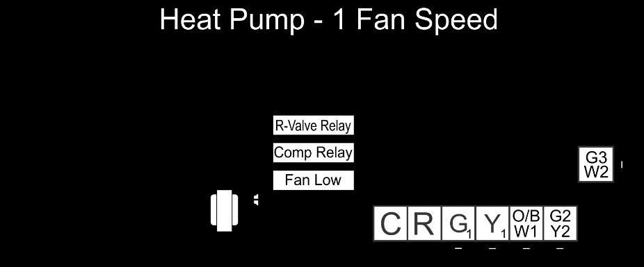
11 Switch 2 Equipment Type Both heat with add on cool or heat pump types of systems can be controlled by the SMT-400. This switch defines how the equipment relays operate. Heat Cool systems use the W terminal(s) only for heating and the Y terminal(s) only for cooling. Heat Pump systems use the Y terminal(s) for BOTH heating and cooling (the compressor). The W1 terminal controls the reversing valve which defines the heating or cooling mode and the W2 is used for Auxiliary heat or emergency heat as defined in the Installer menu (option 17 on page 18 describes this function). Switch 3 Equipment Stages When it is necessary to control a single stage A/C system fitted with auxiliary heating elements, turn Sw3 OFF thereby selecting single stage mode. Heating elements controlled by the W2 output are now assigned as stage 2 heat. (Note, if SW 1 = ON this switch function is internally set as OFF Single Stage) Switch 4 Reversing Valve or Fan Mode When the SMT-400 is set for Heat Pump mode (Sw2 is on) then this switch sets the reversing valve logic (O/B). When the SMT-400 is set for Heat Cool mode (Sw2 is off) then this switch sets the mode for the Heater Fan Logic (HG or HE mode). If SW 2 = OFF then SW 4 Off = Heating Gas. ON Heating Electric. If SW 2 = ON then SW4 Off= Rev Valve in Cool. On = Rev Valve in Heat. Switch 5 Anti Cycle Timer (Compressor Delay) To protect some A/C systems it is recommended that the compressor does not start within 4 minutes of it switching off. Note: When power is first applied to the SMT-400 it assumes that the compressor has just stopped and applies this anti cycle delay time before starting. Switch 6 Klixon mode This function uses a mechanical input to set the mode for a 2-pipe system. 2 pipe modes must be defined for one of the universal inputs in the Installer menu. Installer option 43, 44 or 45 to option 4. Switch 7 Heat Pump Mode The SMT-400 can control both a conventional Heat Pump or a Heat Pump fitted with a Fossil Fuel system. In Australia, Asia and Europe this type of heat pump is not typically used so it is recommended to leave this switch in the OFF position. North America customers may need this function depending on the type of Heat Pump under the SMT-400 control. Switch 8 Not currently used Typical Drawings The SMT-400 has the capacity to control a wide selection of heating, cooling and air conditioning systems as well as modulating valves or other devices. Using the 8 DIP switches (see page 10 and many installer software options (see page 15), the SMT-400 can provide many different control methods from its 6 fitted relays and 3 x 0-10 volt outputs. Examples of only the most common types of control wiring have been provided below. You may need to modify these drawings slightly to specifically suit your individual needs, alternatively contact Smart Temp at support@smarttemp.com.au or an authorised Smart Temp distributor for installation advice specific to your application. 11 P age
12 12 P age
13 13 P age


14 Using Remote Temperature Sensors If the SMT-400 is installed in a location not suitable for accurate temperature measurement you can connect single (or multiple) remote room air temperature sensors and wire these sensors to the SMT-400 Auxiliary input terminals. Using the remote sensor, the SMT-400 can then measure temperature at a distant location from the SMT-400 or measure temperature over a larger area and control using the average temperature of these multiple locations. The Smart Temp remote sensors have an internal switch that changes the function of each sensor in RS-1 mode or RS- 2 mode. Detail on this switch setting is provided in the manual supplied with the Smart Temp sensors. RS-1 Sensor Mode Sensor switch is ON RS-2 Sensor Mode Sensor switch is Off. Please note the configuration of the remote sensors in the examples provided taking note of the switch settings or inaccurate temperature measurement will result. Other sensor configurations are also available. Please note you must define the desired universal input for remote sensing or average temperature measurement. See installer option 40, 41 & 42 on page 21. A typical maximum of 40 meters is permitted for sensor runs with 0.3mm or larger shielded cable should be used. When used in Start/Stop commercial mode (Dip SW8=On), the afterhours run timer can be toggled on or off as required with a momentary press button on the remote sensor. As the SMT-400 auto detects sensors connected to the Auxiliary input terminals, temperature sensors can also be switched on and off as required by placing a switch in the sensor wiring to open circuit the sensor loop. Attaching the Thermostat Check that the position of the 8 DIP switches matches the requirements of the equipment being controlled and the specific requirements of the user. Detailed information on the 8 DIP switches can be found on page 10 of this manual. Check the wiring matches that of the equipment the SMT-400 is to control and that all wiring is tight and not likely to short between adjacent wires. Equipment wiring information can be found on page 11 of this manual. If using the ModBus communication capability of the SMT-400, ensure the A & B data wires are in the correct position as an error here may affect the communication of the entire network. See page 27 for detailed wiring of the communications port of the SMT P age


15 Using masking tape or similar, block the hole in the wall where the wiring enters the back of the thermostat to prevent drafts that may travel down the inside of the wall cavity affecting the accuracy of the internally fitted temperature and humidity sensor. When attaching the thermostat to the base, avoid twisting the case as this may stress the LCD and cause it to crack. Avoid running wiring near the internally fitted sensor. Take care not to damage or crush the temperature sensor between the two halves of the case when you close the case. Check this sensor location. Advanced Installer Settings The SMT-400 is fitted with many advanced functions that can be finetuned by the installer to specifically match the needs of the user s project. Normally these functions will not need to be altered from the factory default position however, there may be times when you wish to alter a setting or control capability so that the SMT-400 performance will perfectly match a particular application. On the next few pages there is detailed explanation of these functions and their range of control. While in the advanced installer menu, all SMT-400 equipment control functions will be suspended. Normal equipment operation will continue when you have exited this menu (after any anti cycle delays or safety delays have terminated). Entering the Installer Menu To enter the Installer menu, press and hold the centre of the LCD for 15 seconds. After 15 seconds, the LCD will show 15 (one five). Adjust this value to 21 (two one) the factory default PIN (or your previously selected value) by using the up ( ) or down ( ) button. Tap the centre of the LCD to enter the menu. If you have entered the correct PIN you will be given the first menu option, if you have entered an incorrect PIN you will be exited from this menu. Using the Installer Menu To move forward through the Installer menu items, tap the arrow to the lower right. To move backwards through the Installer menu items, tap the arrow to the lower left. To adjust the current option, tap the up or down arrows. To exit the installer menu, press and hold the centre of the LCD for 3 seconds or wait 60 seconds and the menu will be exited automatically. 15 P age
16 1 Keyboard Lock PIN This is the required PIN for future entry into the Installer menu. Default is 21. Range 00 to 99 in 01 steps. To prevent accidental PIN changes, you must press and hold the or buttons for longer than 1 second to change the PIN value. (Caution, if you change this value and forget your new PIN, you may need to return the SMT-400 to place of purchase for unlocking, there may be a fee for this service) 2 Beeper Controls the beeper that acknowledges each button press. 0 Beeper OFF 1 Beeper On. (Default) 3 Backlight Brightness in standby mode Controls the level of the backlight when the buttons are not pressed. Range 0-20 Default = 10 4 Auto Backlight Brightness Controls the level of the backlight based on internet dusk setting. (Note SMT-400 must be connected to internet and accurate location set) 0 Off (Default) 1 On 5 Backlight Daytime Brightness hours Controls the level of the backlight based on internet time. (Note SMT-400 must be connected to internet and accurate location set) Range 0-23 Default = 7 6 Backlight Night Time Brightness hours Controls the level of the backlight based on internet time. (Note SMT-400 must be connected to internet and accurate location set) Range 0-23 Default = 19 7 Buttons Shown This defines what buttons are shown on the SMT-400 LCD. A hidden button cannot be adjusted 0 All Buttons are shown. (Default) 1 Mode is shown but Fan is hidden 2 Fan is shown but Mode is hidden 3 Mode and Fan and hidden (Note the temperature setpoint range for Heating and Cooling can be limited in the Heat Limit & Cool Limit menu options below. Option 11 & 12 below) Note: If the mode button is hidden, the service and maintenance staff can turn the SMT-400 on or off by pressing and holding the lower left of the LCD for 15 seconds. 2 chirps indicate the SMT-400 has turned ON. 1 chirp indicates the SMT- 400 has turned off. 8 Permitted Modes The SMT-400 operational modes can be set to set to suit the demands of the user or the limits of the heating and cooling system. Selecting the options below defines how the mode button operates 0 Off and Auto (Heat & Cool). (it will NOT display current mode) 1 Off, Auto (Heat & Cool), Heat, Cool. (Default) 2 Off, Heat, Cool. 3 Off, Heat. 4 Off, Cool. 5 Off and Auto only (Heat & Cool). (Will display current mode) 16 P age
17 9 Room and Set Temperature Display The SMT-400 operational modes can be set to set to suit the demands of the user or the limits of the heating and cooling system. Selecting the options below defines how the mode button operates 0 Shows both Room and Set Temperature. (Default) 1 Displays the set Temperature only. (Note, if option 1 is selected, the main temperature display will show the current (or last mode) set point as room temperature) 10 Temperature Display Format This option effects all user and installer menu items Deg C or Deg F as the native temperature format. 0 Displays in Deg C. (Default) (Note, set point adjustment in 0.5C, temperature display in 0.1C) 1 Displays in Deg F. (Note, set point adjustment, and display in 1F) 11 High Range Limit This value sets the maximum temperature the user can select. The next highest value above this is OFF. When the user attempts to set a temperature above the Off Value the SMT will flash the padlock symbol, Display Set Point Limit Reached text and chirp the beeper twice. Note - This is NOT the Heat Set Point limit. The heat setpoint limit is option 62 on page 23 of this manual. Deg C Range is 5C to 45C (Default 30C) Deg F Range is 41 to 113 (Default 90F) 12 Low Set Temperature Range Limit This value sets the minimum temperature the user can select. The next lowest value below this is OFF. When the user attempts to set a temperature below this Off Value the SMT will flash the padlock symbol, Display Set Point Limit Reached text and chirp the beeper twice. Note - This is NOT the Cool Set Point limit. The cool setpoint limit is option 63 on page 23 of this manual. Deg C Range is 5C to 45C (Default 5C) Deg F Range is 41 to 113 (Default 41F) 13 Dead band This sets the difference that must be maintained between the heating and cooling setpoint. If when adjusting a setpoint it is too close to the other setpoint, the SMT-400 will automatically "push" the other setpoint away to maintain this dead band value. Deg C Range is 1C to 5C (Default 1C) Deg F Range is 1 to 10 (Default 2F) 14 Heat Relay Span This defines how far from the heating set point the stage 1 heat relay will energise to engage heating. If the SMT-400 is set for multistage heat control, then stage 2 also uses this value. Adjustable range Deg C 0.5c to 3c (default is 1c) (in 0.1c increments) Adjustable range Deg F 1.0F to 6F (default is 2F) (in 0.1F increments) 15 Cool Relay Span This defines how far from the heating set point the stage 1 cool relay will energise to engage cooling or compressor. If the SMT-400 is set for multistage cool control, then stage 2 also uses this value. Adjustable range Deg C 0.5c to 3c (default is 1c) (in 0.1c increments) Adjustable range Deg F 1.0F to 6F (default is 2F) (in 0.1F increments) 17 P age
18 16 Indoor Fan Reset When the SMT-400 mode is set to OFF the fan, mode will change to the settings below. 0 Fan mode will remain unchanged Continue in Fan Auto or Fan ON mode. 1 If Fan On, Fan Mode will change to Auto mode and remain in Auto. (Default) 2 If Fan On, Fan Mode will change to Auto and remain in Auto. Fan button will be hidden. 3 If Fan On, Fan mode will temporarily change to Auto and return fan on when SMT-400 is on. 4 If Fan On, Fan mode will temporarily change to Auto and return fan on when SMT-400 is on. Fan button will be hidden while mode is off. 5 If enabled, the indoor fan mode will reset to Auto Fan Mode 1 hour after the thermostat mode is set to Off. 17 Fan Purge The SMT-400 can ensure the evaporator fan runs past the heating and cooling calls if required. 0 No Fan Purge. 1 Fan Purge 1 minute. 2 Fan Purge 3 minutes. 3 Fan Purge 5 minutes. 4 Fan Purge 10 minutes. 5 Heat Only Mode Fan purge 1 Minute. 6 Heat Only Mode Fan purge 3 Minutes. 7 Heat Only Mode Fan purge 5 Minutes. 8 Heat Only Mode Fan purge 10 Minutes. 9 Cool Only Mode Fan purge 1 Minute. 10 Cool Only Mode Fan purge 3 Minutes. 11 Cool Only Mode Fan purge 5 Minutes. 12 Cool Only Mode Fan purge 10 Minutes. 18 Fan Span (3 Fan Speeds) When the SMT-400 is set for 3 fan speeds, this option defines the temperature differential between fan stages. Deg C 0.5C to 3.0C (1c Default) (Adjustment 0.1c steps) Deg F 1.0F to 6.0F (2F Default) (Adjustment 0.1F steps) 19 W2 Relay Function 0 W2 relay is used as 2nd (or 3rd) stage Auxiliary heat. (Default) Options below Only operates in single fan speed HP mode (SW1 = OFF, Sw2 = ON). 1 W2 relay is used to control an Emergency Heating system. 2 This will permit both Aux heat & Emergency Heating mode (both use W2 relay) 20 E. Heat Compressor When option 19 is set for Emergency Heat, this option will define how the Heat Pump system operates when Emergency Heat is running. 0 Compressor stops with E.Heat. (Default) 1 Compressor still runs with E.Heat. Note This function DOES NOT interlock the fan with compressor output. If you wish the fan to come on with the compressor in E.Heat mode turn on E.Heat Fan Below. 21 E. Heat Fan When option 19 is set for Emergency Heat, this option will define how the Evaporator fan operates when Emergency Heat is running. 0 Fan stops with E.Heat. (Default) 1 Fan runs with E.Heat. 18 P age
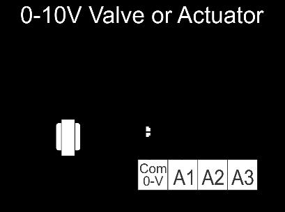
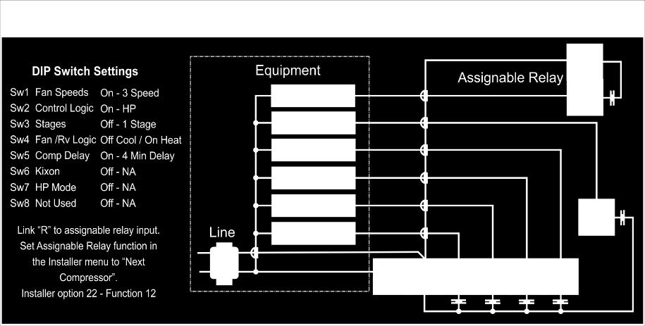
19 22 Assignable Relay Functions The SMT-400 has a volt free 24V max) relay with changeover contacts that has a selection of functions. Some functions have a threshold that can be applied to them, installer adjusts this threshold value option number 23 (below). 0 Relay not used 1 Humidity Alarm 2 Temperature Alarm 3 Occupancy Status (Relay energised when Occupied) 4 Heat Output Energised whenever SMT-400 is demanding a heat V heat Output Energises whenever SMT v heat output is not 0V 6 Cool Output Energised whenever SMT-400 is demanding a cool V cool Output Energises whenever SMT v cool output is not 0V 8 Heat & Cool Output Energised when SMT-400 is demanding heat or cool V heat & cool Energises whenever the 0-10v Heat or cool output is not 0V 10 Fan output Energised when SMT-400 Fan is running V Fan out put - Energised when SMT v Fan is not 0v 12 Next Stage compressor (permits 2 compressor systems to run with 3 fan speeds). 13 Next Stage Heating. (HC mode). 14 Next Stage Cooling (HC mode). 15 CWP mode, the relay will output when heating or cooling is needed even if the SMT-400 is in fault mode. 16 The Assignable relay will be controlled via the Smart Temp Comfort App. 23 Assignable Relay Threshold Where the assignable relay (as described above) automatically changes status based on a variable value (such as option 1 temperature or option 2 RH) this setting determines that threshold. Range is 0 to 100. This can be deg C/F for temperature or 0-100% RH for example v Output v Output v Output 3 The SMT-400 has 3 independent 0-10v outputs. Each output has the same library of functions. A more detailed description of the 0-10V output functions can be found on page 26 of this manual. 0 Modbus Network Controlled (Default). The ModBus network can write a value to this output. 1 Heat Output Used to control a valve or other heating device. 2 Cool Output Used to control a valve or other cooling device. 3 Heat and Cool Output Used to control capacity control device. 4 Fan output used to control a DC fan. 5 Fresh Air Damper Used in economy cycle damper control. 6 Return Air Damper Used in economy cycle damper control. 7 RH output to provide an output in proportion to the current RH value. 8 Belimo 6-way valve control see page 25 for more information v Heat Span This value sets how far from set point the 0-10V heat output is at 10V. Adjustable range Deg C 0.5c to 3c on 0.1c increments (default is 1c) Adjustable range Deg F 1.0F to 6F on 0.1F increments (default is 2F) v Heat Interval (PI) This value sets the time interval for the 0-10V Heat Valve Proportional Integral calculation. Range 10 to 300 Seconds. (Default 60 seconds) v Heat Direction To suit both forward and reverse action values, the 0-10V output direction for the heat valve can be defined. 0 Forward acting 0 10V 1 Reverse acting 10 0V 19 P age
20 v Heat Minimum Voltage This is the lowest voltage that will be applied to the 0-10V Heat valve when the heating is called. Adjustable range is 0.1 to 10V in 0.1v increments (default is 0.1v) v Cool Span This value sets how far from set point the 0-10V cool output is at 10V. Adjustable range Deg C 0.5c to 3c on 0.1c increments (default is 1c) Adjustable range Deg F 1.0F to 6F on 0.1F increments (default is 2F) v Cool Interval (PI) This value sets the time interval for the 0-10V Cool Valve Proportional Integral calculation. Range 10 to 300 Seconds. (Default 60 seconds) v Cool Direction To suit both forward and reverse action values, the 0-10V output direction for the cool valve can be defined. 0 Forward acting 0 10V 1 Reverse acting 10 0V v Cool Minimum Voltage This is the lowest voltage that will be applied to the 0-10V cool valve when the cooling is called. Adjustable range is 0.1 to 10V in 0.1v increments (default is 0.1v) Adjustable range Deg F 1.0F to 6F on 0.1F increments (default is 2F) v Fan Span This value sets how far from set point the 0-10V Fan output is at 10V. Adjustable range Deg C 0.5c to 3c on 0.1c increments (default is 1c) Adjustable range Deg F 1.0F to 6F on 0.1F increments (default is 2F) V Fan Interval (PI) This value sets the time interval for the 0-10V fan Proportional Integral calculation. Range 10 to 300 Seconds. (Default 60 seconds) V Fan Direction You can define the 0-10v logic for the control for 0-10V fan logic 0 Forward action 0-10V= Slow to fast 1 Reverse action 10-0V = Slow to fast V Fan Minimum Voltage To prevent a fan motor potentially running too slowly, the SMT-400 permits you to set a minimum fan run voltage. This is the lowest voltage that will be applied to the fan when the fan is running. Adjustable range is 0.1 to 10V in 0.1v increments (default is 0.1v) V Fan Maximum Voltage To prevent excessive fan noise the fan motor maximum speed can be limited. This setting defines the highest voltage that will be applied to the fan when the fan is running. Adjustable range is 0.1 to 10V in 0.1v increments (default is 10V) 20 P age
21 40 Universal Input 1 41 Universal Input 2 42 Universal Input 3 The SMT-400 has 3 independent universal inputs. Each input has the same library of functions. A more detailed description of the universal input functions can be found on page 28 of this manual 0 Input not used 1 Remote Sensor Used to replace the fitted sensor. 2 Average Use average both remote and fitted for control. 3 Data Sensor value used for Modbus only. 4 Duct sensor Used for 2 pipe mode control. 5 Outside Air Sensor Used to display outside air temperature. 6 Window Input Used to detect status of Window contact. 7 Door Input. Used to detect status of Door contact. 8 PIR Input. Used to detect status of Movement detector. 9 Fault Input. Used to shut down equipment outputs if a Fault is detected. 10 Fault Input No Indication As option 9 above but Fault is not shown on the LCD. 11 Force unoccupied Mode. Will force the use of Unoccupied set points. 12 Warm Start - will delay fan starting in electric heat mode 13 De-Ice Sensor will change reversing valve and suspend fan if condenser ices. 14 Will Force the SMT-400 mode to OFF. 43 Calibration Fitted Temperature Sensor Calibration Offset for the internal temperature sensor. Adjustable range Deg C +/- 4.5C Default value 0.0 Adjustable range Deg +/-9F. 44 Calibration Remote Temperature Sensor Calibration Offset for the remote temperature sensor (if used). Adjustable range Deg C +/- 4.5C Default value 0.0 Adjustable range Deg +/-9F. 45 Heat Off Temperature If the optional outside air temperature sensor is fitted and the outside air temperature exceeds this value by more than 1c the heating function will be suspended until the outside air temperature falls to below this threshold. The text "Heat" & "Locked" will flash to indicate heating has been disabled. Deg C Range is Off, then 5C to 45C Deg F Range is Off, then 41 to Cool Off Temperature If the optional outside air temperature sensor is fitted and the outside air temperature falls below this value by more than 1c the cooling function will be suspended until the outside air temperature raise above this threshold. The text "Cool" & "Locked" will flash to indicate heating has been disabled. Deg C Range is Off, then 5C to 45C Deg F Range is Off, then 41 to High Balance Point If the optional outside air temperature sensor is fitted and the outside air temperature exceeds this value, only stage 1 is permitted until the outside air temperature falls to below this threshold. This function operates regardless of whether the SMT-400 is in Heat cool or Heat Pump mode. Deg C Range is Off, then 5C to 45C Deg F Range is Off, then 41 to P age
22 48 Low Balance Point This function only functions when the SMT-400 is set for Heat Pump mode (Sw2=ON), if the optional outside temperature sensor is fitted and option 19 (W2 function = options 1 - Eheat) is selected. When the outside temperatures falls below this value the SMT-400 will automatically select Emergency Heat Mode. Deg C Range is Off, then 5C to 45C Deg F Range is Off, then 41 to Window Input Logic If one of the universal inputs (options or 42) are set as a window input, this register defines the logic for that input. 0 Normally Open logic (Default) 1 Normally Closed Logic 50 Window Input Delay If one of the universal inputs (options or 42) are set as a window input, this register defines how long the input must be active before the function is initiated. Range seconds (Default is 30 seconds) 51 Door Input Logic If one of the universal inputs (options or 42) are set as a door input, this register defines the logic for that input. 0 Normally Open logic (Default) 1 Normally Closed Logic 52 Door Input Delay If one of the universal inputs (options or 42) are set as a door input, this register defines how long the input must be active before the function is initiated. Range seconds (Default is 180 seconds) 53 PIR Input Delay If one of the universal inputs (options or 41) are set as a PIR input, this register defines how long the input must be active before the function is initiated. 1 to 180 minutes (3 minutes default) 54 Auto Off Timer / Commercial after hours timer The SMT-400 can be set to automatically turn itself off in a predefined time after it has been turned on. If the SMT-400 is set to commercial mode, this is the time the SMT-400 will run for before automatically returning to setback mode. Adjustable range 0-10 hours in 0.5 hour increments (Default is (1 hr = 10) 55 Unoccupied Mode Heat set point This option defines the heating temperature the will be used when the SMT-400 is in Un-occupied mode. Adjustable range is 0.1 to 10V in 0.1v increments (default is 0.1v) Adjustable range Deg F 1.0F to 6F on 0.1F increments (default is 2F) 56 Unoccupied Cool set point / Commercial Cool set back temperature This option defines the heating temperature the will be used when the SMT-400 is in Un-occupied mode. Adjustable range is 0.1 to 10V in 0.1v increments (default is 0.1v) Adjustable range Deg F 1.0F to 6F on 0.1F increments (default is 2F) 22 P age
23 57 Unoccupied Fan mode This option defines the fan mode that will apply in un-occupied or commercial mode when the building empty. In 3 Fan Speed mode, you have all options, in single Fan speed mode option 1 & 4 are permitted. 1 Low (Auto) (default) 1 Auto (single fan speed mode) 2 Med (Auto) 3 High (Auto) 4 Low (ON) 4 ON (single fan speed mode) 5 Med (ON) 6 High (ON) 58 De-ice fan 0 Evaporator Fan stops during de-ice (Default) 1 Evaporator runs during deice (limited to low fan speed if 3 speed mode selected) 59 Modbus Address This sets the SMT-400 ModBus address on the network. Range seconds (Default is 7) 60 Modbus Speed This sets the SMT-400 ModBus communications speed bps bps (Default) bps. 61 Modbus Parity This sets the SMT-400 ModBus communications parity. 0 None (Default) 1 Odd 2 Even 62 Heat setpoint limit This is the highest heat setpoint the user is permitted to set. When the user attempts to set a heating temperature above this value the thermostat will chirp and display the text Set Point Limit Reached Deg C Range is 5C to 45C (Default 30C) Deg F Range is 41 to 113 (Default 90F) 63 Cool setpoint limit? This is the lowest cool setpoint the user is permitted to set. When the user attempts to set a cooling temperature below this value the thermostat will chirp and display the text Set Point Limit Reached Deg C Range is 5C to 45C (Default 5C) Deg F Range is 41 to 113 (Default 41F) 64 Hide RH and outside air temp when OFF 0 Always display Outside air & RH values (Default) 1 Hide RH & Outside air values in OFF mode 65 Turn mode to OFF is Wi-Fi is lost 0 Disabled (Default) 1 Enabled To prevent excessive energy consumption when Wi-Fi is lost, the SMT-400 can be set to automatically turn off 30 minutes after Wi-Fi is lost. This function can also be enabled or disabled from the Smart Temp Comfort App. 23 P age
 1 Reset SMT-400 (exit to enable) Control Logic The SMT-400 will turn on the first stage of heating or cooling at the Span distance (as defined in the installer menu) from set point.")

24 R Reset SMT-400 to factory default This function clears all thermostats back to factory settings. Note, this does NOT reset the Wi-Fi Radio. 0 Off (Default) 1 Reset SMT-400 (exit to enable) Control Logic The SMT-400 will turn on the first stage of heating or cooling at the Span distance (as defined in the installer menu) from set point. It will turn stage 1 heating and cooling off at the set point. If Sw 1 is off and the room temperature reached the stage 2 heating and cooling set points the SMT-400 will turn on stage 2 outputs. Stage 2 heating or cooling will turn off at 0.3c from set point. Commissioning As with any thermostat, commissioning ensures that the thermostat and the equipment connected to it are operating correctly and as expected. Follow the steps detailed below and use the troubleshooting guide on page 31 if you encounter any problems. When the thermostat is fitted to the base plate and when 24VAC power is first applied, the LCD should briefly show all available segments (a LCD function test) then display the software version number before showing the time and operating mode etc. Test Fan Operation With the thermostat mode OFF (tap the mode button to show OFF in the LCD), simply tap the fan button to cycle through the available fan speeds. As the LCD changes to show the fan speed or fan mode you should here faint clicks as the SMT-400 internal relays change. The equipment fan speed should change accordingly. Test Heating and Cooling (if both fitted) Turn the SMT-400 to Auto season mode (if available). To change mode tap the mode button until the words Heat and Cool are shown on the LCD. Using the temp or temp button, set the desired heat temperature a few degrees above the ambient temperature. After a few moments, you will hear a click and the word Heat will flash. Verify that the heating system is on and operating correctly. If stage 2 heat is being called the full stop. between the digits of the room temperature display will flash. If Stage 3 is on the full stop will flash rapidly. Using the temp + or temp button, set the desired cool temperature a few degrees below the ambient temperature. After a few moments, you will hear a click and the word Cool will flash. Verify that the cooling system is on and operating correctly. When stage 2 cool is being called the full stop. between the digits of the room temperature display will flash. If Stage 3 is on the full stop will flash rapidly. Tap the mode button turn the SMT-400 OFF. After any necessary timers, have expired all heating, cooling and fan functions should stop. Verify that the system has shut down. Note: In HP mode (SW2=ON) it is normal for the reversing valve to remain energised after the compressor has stopped. This is done to prevent de-compression HISS and to limit the wear on the reversing valve. 30 minutes after the last reversing valve use it will de-energise to conserve power. Commissioning is complete. 24 P age
25 Advanced Functions Universal Input Functions The SMT-400 is fitted with three universal inputs. These inputs can be used for a digital (On/Off) input or a Smart Temperature sensor input. You are then able to define the function of the inputs with the options below. Remote Sensor - when this option is used, the sensor on board the SMT-400 is disabled and the remote temperature senor(s) is used exclusively for room temperature measurement. Average when averaging is selected, both the on-board and remote sensor(s) are used and the SMT-400 will display and control to the average of these two sensors. Data This option is used when you only wish to view the value on a ModBus network, such as when you need monitor the supply air temperature for example. This value does NOT have any influence on how the SMT-400 functions. It is display on ModBus Only. Duct sensor when the SMT-400 is used to control a fan coil with two pipes, strapping a sensor to the fan coil pipe will permit the SMT-400 to automatically select the appropriate mode based on pipe temperature. Outside Air Sensor the SMT-400 can display the outside air temperature for your location if you have it connected via Wi-Fi, however this internet based weather is not accurate for more advanced control functions. Fitting a wired sensor to the SMT-400 overcomes these inaccuracies. Window Input The window input will force the SMT-400 to OFF mode after a present period as defined in option 49 of the installer option menu. The SMT-400 will flash the word OFF in the display to inform that it is held off via a remote input and tapping the mode button will have no effect. The window input is designed as an energy saving feature so that if the user leaves windows (or doors) open for too long its probably pointless to run the heating and cooling system, so it is turned off until the window is closed. Door Input The door input is used for 2 functions. Firstly, it is used as part of the room occupancy detection logic to detect whether a person has entered or exited the room (used in conjunction with the SMT-400 PIR input). Secondly, the door input will force the SMT-400 to OFF mode after a present period as defined in option 51 of the installer option menu. The SMT-400 will flash the word OFF in the display to inform that it is held off via a remote input and tapping the mode button will have no effect. If the door input detects that the door is held open for too long its probably pointless to run the heating and cooling system, so it is turned off until the window is closed. PIR Input Is used as part of the room occupancy detection system by seeking movement after the door to the room is closed. If movement is seen after the door is closed then the SMT-400 is held in Occupied Mode, if no movement is seen after the door is closed the SMT-400 will be in un-occupied mode. See Occupancy detection logic on page 28 of this manual. Fault Input When this input it triggered the SMT-400 will instantly shut down, all relays off. All 0-10V at 0v (all run timers or purge periods etc will be ignored). The text Fault will be displayed on the LCD. Fault Input No LCD Indication When this input it triggered the SMT-400 will instantly shut down, all relays off. All 0-10V at 0v (all run timers or purge periods etc will be ignored). Fault will NOT be displayed on the LCD. Force unoccupied Mode Will force the use of unoccupied set points and un-occupied mode. Most useful in a hotel room with a door card system or to be used by a building management system to set the occupancy stats of the room. Warm Start If selected the SMT-400 will monitor the optional sensor mounted on the evaporator call and hold of the indoor fan starting until the coil temperature is greater than 25c or 45 seconds whatever occurs first. (only available if the SMT-400 is in HP mode; Switch 2 on). De-Ice If selected and when heating, the SMT-400 will monitor the temperature of the optional sensor installed on the condenser coil and wired to the SMT-400 universal input. If the Condenser coil temperature drops to -2c (28F) or below the SMT-400 will change the reversing valve state to heat the condenser and melt the ice. Once the condenser temperature exceeds 10c (50F) the reversing valve will change to the correct position for heating. You are permitted to select whether you require the evaporator fan to run or stop during the de-ice process (including the warm start functions as described above). 25 P age
26 Force OFF This input forced the SMT-400 mode to OFF. The word "Off" will flash in the display to indicate the remote OFF function is operating. PIR Only occupancy mode - selecting this mode the SMT-400 will monitor the input for change of status from on to off or off to on as would be expected to receive from a standard PIR sensor. After the defined period without a status change of the input the SMT-400 will replace the user setpoints with the un-occupied setpoints and display the word "Un-Occupied" on the display. 0-10V Output Functions Heat Valve Used to control a heating valve or any other device that requires a 0-10V PI output for heating. Cool Valve Used to control a cooling valve or any other device that requires a 0-10V PI output for cooling. H&C output Where you need a single 0-10v output for heating and cooling such as a 2-pipe system or for capacity control on a digital scroll for example. Fan Used to control a 0-10V DC fan. You can also set the minimum and maximum voltages that can be applied to this output. Fresh air Damper - To be used in conjunction with the fresh air economy cycle function of the SMT-400. See page 27 for more details. Return Air Damper To be used in conjunction with the fresh air economy cycle function of the SMT-400. See page 27 for more details. Assignable Relay Functions Rh The relay will energise when the wall controller RH exceeds the defined threshold as set by installer option number 47 (page 19). Temperature The relay will energise when the wall controller temperature exceeds the defined threshold as set by installer option number 47 (page 19). Occupied The relay will energise whenever the room is detected (or told via a universal input) that the room is un-occupied. This output can be used to isolate room electrics for example. Heat The relay will energise whenever the SMT-400 is calling for heat. Cool The relay will energise whenever the SMT-400 is calling for cool. Heat & cool The relay will energise whenever the SMT-400 is calling for cool or heat. Next Compressor In Heat Pump Mode. The assignable relay will be next stage compressor such as Compressor 2 in 3 fan speed mode or compressor 3 in single fan speed mode. This stage will use the span setting of the previous stage. Note. The SMT-400 will apply a 3-minute fixed timer between stages. Next Stage Heating- In Heat cool mode. The assignable relay will be Next Stage Heat such as Heat 2 in 3 fan speed mode or Heat 3 in single Fan speed Mode. This stage will use the span setting of the previous stage. Note. The SMT-400 will apply a 3-minute fixed timer between stages. Next Stage Cooling - In Heat cool mode. The assignable relay will be Next Stage Cool such as Cool 2 in 3 fan speed mode or Cool 3 in single Fan speed Mode. This stage will use the span setting of the previous stage. Note. The SMT-400 will apply a 3-minute fixed timer between stages. CWP Output The assignable relay will energise when the SMT-400 calls for heating or cooling even if the fault input is holding the equipment relays off (and 0-10V output at 0v). This function permits the SMT-400 to be used on water sourced heat pumps and to call for a water pump start if heating or cooling is needed even though the equipment outputs are held off. (see Fault input on page 25 ) 26 P age


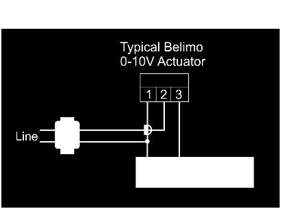
27 ModBus Communications The SMT-400 has integrated ModBus communications capabilities where using a remote PC or building Direct Digital Control (DDC) system you may view or adjust many of the SMT-400 functions remotely. A typical ModBus wiring example is given above. If using a common power supply to power all thermostats on a network, it is highly recommended that all thermostats power is wired in phase, i.e. R to R and C to C and NOT crossed. It is essential that the network be wired as a daisy chain as shown in the drawing above. The communications port of the SMT-400 has 2 terminals used for communication. A, & B. Terminals A+ & B- are used for data communication, A maximum of 255 SMT-400s can be connected to any single hub. Each SMT-400 on the hub must have a unique network address (factory default is 7). These settings are adjustable from the advanced installer menu. See installer options 54, 55 & 56 on page 23 for more detail on setting the communications address. In many cases where multiple thermostats are used in a single network node, or on a long network run the last device in the node should have a 120Ω resistor across the A B terminals. Short communication runs under 5m 1mm (18 gauge) twisted pair unshielded wire can is suitable, however for longer runs (>5M) or where electrical noise may be present twisted pair with shield should be used. The shield drain on the cable should be earthed. It is not the scope of this manual to provide detail on the communication capability of the SMT-400. Detailed ModBus communications detail is available for download from the download page at or from an authorised Smart Temp Distributor. Outside air economy cycle The SMT-400 can provide an outside air economy cycle function to help cool your home or office with the use of fresh air if suitable. The wiring diagram provided below is one example of how to wire up economy cycle function. This example is provided using Belimo 24V modulating dampers, other dampers can be used if desired. Economy cycle Logic. The SMT-400 will first check that an outside air sensor is wired to one of the Auxiliary inputs and that the input is assigned as Outside air function (I.E the SMT-400 is showing outside air temperature on the LCD), secondly the SMT-400 will check to see that at least one 0-10V output is assigned as Fresh Air or Return Air function. Should you wish you can assign one 0-10V output as Fresh Air and another 0-10V output as Return Air. If both conditions are met, then the SMT-400 will enable economy cycle. When Economy Cycle is not being used the Fresh Air damper output will be 0v. The Return Air damper will be at 10v. (The sum of both outputs always = 10V) When cooling is required and If the outside air temperature is at least 3c below the current room temperature then the SMT-400 will start Economy cycle cooling. The LCD will display the text Fresh Air in Use. If the indoor fan is in Auto Mode (Cyclic fan) and not running when the Economy Function is required, then the SMT-400 will automatically start the indoor fan. For each 0.1C the room temperature is above the cooling set point the SMT-400 will apply 2v to the Fresh Air damper (and remove 2v from the return air damper). When the room temperature is 0.5v above the Set point the SMT-400 will be on full fresh air. (Return air will be 0V and the Fresh Air will be 10v). 27 P age
28 Economy cycle will be suspended when the temperature differential between the outside air and room temperature drops to below 2c, or the room temperature increases to the point where the cooling relay (Y1) is energised or the SMT- 400 mode is turned to heat only mode or off. High and Low Balance Points The SMT-400 is fitted with both High and Low Balance Point control capability. For these functions to operate the installer setting must have one of the universal inputs set for Outside air temperature measurement, the outside air sensor must be installed and SW1 must be OFF (Single fan speed mode). High Balance Point Set the installer menu value option 13 to a temperature value that will initiate the High Balance point function. When the outside air temperature is above this value, second or third stages of heating are held off regardless of the room and set temperature. Setting this function is designed to prevent the excessive consumption of energy for heating when the outside air temperature is warm. Low Balance Point SW2=ON (Heat Pump Mode), Installer menu 17 = option 1 E.Heat (Emergency Heat Mode) Set option 13 in the installer menu to the value that when the outside air temperature is below this value the SMT-400 will automatically switch to emergency heat mode when heating is required. If the outside temperature is above this Low balance point value, the emergency heat mode can be selected manually at any time with the MODE button. Setting Up the Heat & Cool Off Functions To conserve energy, the SMT-400 can suspend the heating or cooling functions completely if the outside air temperature is outside a prescribed installer set range. If the outside air temperature as measured by the optional outside air temperature sensor is above the Heat off temperature (as defined in installer option 11) heating will not be called regardless of the room and set temperature. If the outside air temperature is below the Cool off temperature value (as defined in installer option 12), cooling will not be called regardless of the room and set temperature. The text Heat or Cool and the Locked symbol will flash on the LCD to show that these modes have been restricted. Belimo 6 Way Valve R30 #...#... B2 Series Belimo manufactures an actuator that is in full cooling at 2V, off at 6V and full heating at 10V. To use this type of actuator with the Smart Temp SMT-400 you must enter the installer menu and set valve type to Belimo Mode. The heating 0-10v output only is used in this mode As with normal valves, the 0-10V heating and cooling span settings in the installer menu scale the heating and cooling outputs. Factory default is full heating and full cooling 1 C from set point. The heating and cooling span can be adjusted independently to a maximum of full heating and full cooling 3 C from set point. The output is linear. Supply Air Temperature Monitoring Define one of the three Auxiliary Inputs for Data (see page 21) and wire the remote sensor to this input. In this mode, the SMT-400 will broadcast this sensor temperature value to ModBus ONLY. This value is not used by the SMT-400 nor is it displayed on the LCD. It is expected that this information is used for supervisory functions or equipment control feedback. Also, as this is an analogue input, by monitoring a switched resistor network your supervisory software can decode several digital states. Occupancy Detection The SMT-400 has inbuilt occupancy detection logic that can operate in either of two modes. Latched mode is used where there may be extended periods of inactivity while the space is occupied, such as in a hotel room while the guest sleeps. During these periods of inactivity in the space you do not wish the Heating, Cooling or Air Conditioning to shut down. Instant mode simply monitors a movement detector and will put the SMT-400 in un-occupied mode a set period of time after the last movement is detected. Latched mode 28 P age

29 Latched occupancy detection requires the use of two inputs in the SMT-400. Two separate inputs of the SMT-400 are used to test the traffic flow (are people entering or leaving the room). If people have entered the room the SMT-400 will remain latched into occupied mode regardless of whether the people move about or remain still. The two inputs we call Door and PIR inputs for clarity however you don t need monitor a door switch with the door input, a second PIR can be used for this purpose if desired. When the door is first opened the SMT-400 instantly enters Occupied Mode. The SMT-400 will then use the PIR sensor to detect movement in the room. If no movement is seen within the installer pre-set seek time (installer adjustable 1 to 180 minutes) the SMT-400 will enter Un-occupied mode. Should movement be detected within the installer pre-set seek time the SMT-400 will LOCK into Occupied Mode and no longer rely on continued movement within the room to remain in Occupied Mode. Next time the door is opened the SMT-400 will again begin its occupancy detection process. Note - even when the SMT-400 is in un-occupied mode it will continue to use the PIR input to determine room occupancy. For example - a couple may be staying in a hotel room and one person leaves the room leaving the other asleep in bed. As the door closes the SMT-400 will seek movement and when none is found it will enter un-occupied mode. As the sleeper wakes and then moves the SMT-400 will automatically re-enter Occupied Mode even though it may have been some time since the door was closed. Instant Mode Wiring a PIR directly to the PIR input of the SMT- 400 permits you to use the SMT-400 to automatically turn the Air conditioning on when a person enters the space (if seen by the PIR movement detector) and automatically turn if off a set period of time after they leave the space. 29 P age
T-32-TS Touchscreen Thermostat. Installation Manual
 T-32-TS Touchscreen Thermostat Installation Manual TABLE OF CONTENTS Introduction...4 Getting Started...5 Installing the Thermostat...6, 8 Disassembly...6 Thermostat Location...6 Mounting the Subbase...6,
Elegance. SMT-700 User manual. Ver
 Elegance SMT-700 User manual Ver 3.0. 0807 Congratulations on the purchase of your new Thermostat! Your new air conditioning system thermostat has been built using the best components and design philosophy
Installer Manual SMT 770 Chameleon Multifunction Thermostat. Ver 3.0
 Installer Manual SMT 770 Chameleon Multifunction Thermostat Ver 3.0 This document it not typically left with the user as it contains information on setting values which, if not correctly set may damage
Smart Temp. ApolloP/n Installation Manual. Version 1.0
 Smart Temp ApolloP/n 44-800 Installation Manual Version 1.0 TABLE OF CONTENTS Introduction...6 Getting started...7 Installing the thermostat...8 Disassembly...8 Thermostat location...8 Mounting the subbase...8,
SMART 2000 Digital Programmable Thermostat Installation Manual Robertshaw 2/
 SMART 2000 Digital Programmable Thermostat Installation Manual www.robertshaw.com 2015 Robertshaw 2/15 352-00193-001 IMPORTANT SAFETY INFORMATION WARNING: ELECTRICAL SHOCK HAZARD Turn off power at the
Comfort System T-21-P Touchscreen Thermostat Installation Manual
 Comfort System T-21-P Touchscreen Thermostat Installation Manual Version 1.40 INTRODUCTION The Comfort System T-21-P is a feature-rich touchscreen thermostat that can be battery powered or hardwired to
IT801 Thermostat. User s Manual. The complete guide to the set up and operation of your new smart Wi-Fi thermostat.
 IT801 Thermostat User s Manual The complete guide to the set up and operation of your new smart Wi-Fi thermostat. The smart Wi-Fi thermostat system learns your comfort preferences, then finds opportunities
Peak Partners Web-Programmable Thermostat Homeowner s Manual. Look inside for a complete guide to the setup and operation of your new thermostat.
 Peak Partners Web-Programmable Thermostat Homeowner s Manual Look inside for a complete guide to the setup and operation of your new thermostat. Table of Contents Step 1: Getting Started...4-6 A. Thermostat
EL-TSTAT-8820 Safety & Installation Instructions
 EL-TSTAT-8820 Safety & Installation Instructions TABLE OF CONTENTS WI-FI SETUP Wi-Fi Setup 2 INSTALLATION Installation location recommendations 3 Outdoor temperature sensor (included) 3 Remote temperature
Installation Manual for Hot Yoga Studio Electric Radiant Heating Version 3.0
 Comfort System HG-122 Universal Thermostat Installation Manual for Hot Yoga Studio Electric Radiant Heating Version 3.0 More Ah ha! Less Uhhh? For easy to follow programming instructions visit: www.heatinggreen.com/thermostatinstructions-wiring-diagrams/
Installation Manual for Hot Yoga Studio Electric Radiant Heating
 105 Comfort System HG-122 Universal Thermostat Installation Manual for Hot Yoga Studio Electric Radiant Heating Version 3.0 More Ah ha! Less Uhhh? For easy to follow programming instructions visit: www.heatinggreen.com/thermostatinstructions-wiring-diagrams/
PRO Installation. Touch Wi-Fi Thermostat
 PRO Installation Touch Wi-Fi Thermostat 1 Designed by the pros for the pros There are a lot of choices when it comes to buying a thermostat, but only one combines 125 years of experience and the latest
CONTROL ZONE Smart Temp. SMT-700 Installer Manual. Ver 3.0
 CONTROL ZONE Smart Temp SMT-700 Installer Manual Ver 3.0 This document it not typically left with the user are it contains information on setting values which, if not correctly set may damage the heating,
PRO Installation. Thermostat Wi-Fi
 PRO Installation Thermostat Wi-Fi 1 Designed by the pros for the pros There are a lot of choices when it comes to buying a thermostat, but only one combines 125 years of experience and the latest connected
PRO Installation. Touch Wi-Fi Thermostat
 PRO Installation Touch Wi-Fi Thermostat 1 Designed by the pros for the pros There are a lot of choices when it comes to buying a thermostat, but only one combines 125 years of experience and the latest
User Manual. Universal Programmable Smart Wi-Fi Thermostat. For Systems Up to 3 Heat / 2 Cool with Wireless Humidity Control*
 User Manual Universal Programmable Smart Wi-Fi Thermostat 7320 For Systems Up to 3 Heat / 2 Cool with Wireless Humidity Control* See Wi-Fi Setup Guide for Wi-Fi Setup Instructions Read all instructions
Touch Screen Thermostat. MTSC/SUPER/CO2, MTSC24/SUPER/CO2 Series. MTS/SUPER/CO2, MTS24/SUPER/CO2 Series. Owner s manual and technician settings
 Touch Screen Thermostat MTSC/SUPER/CO2, MTSC24/SUPER/CO2 Series MTS/SUPER/CO2, MTS24/SUPER/CO2 Series Owner s manual and technician settings Rev. 2.4 Index 1. Owner s Manual... 3 1.1 Quick Guide. 4 1.2
RCS Residential Control Systems Inc.
 RCS Residential Control Systems Inc. Model TZ16 Z-Wave Communicating Thermostat with Rev P HVAC Control Unit INSTALLATION AND OPERATION MANUAL DCN: 141-00882 Rev 02 5/18/06 This manual applies to the following
Smart thermostat with Humidification/De-humidification control
 x Smart thermostat with Humidification/De-humidification control Enter/Confirm Scroll Right = Increase Left = Decrease Back/Cancel TABLE OF CONTENTS Everyday Use 1. Adjusting Temperature...3 2. Adjusting
EASY ZONE TOUCH. User Manual. 6 Zone Control System with Active Temperature Management. Ver 1.0
 EASY ZONE TOUCH 6 Zone Control System with Active Temperature Management User Manual Ver 1.0 Preface Your new air conditioning zone control system has been built using the best components and design philosophy
Product Manual SZ1009
 Product Manual SZ1009 Conventional Heating & Cooling Thermostats with Heat Pump Mode Communicating Thermostats Description The SZ1009 is a microprocessor-based mable thermostats designed for conventional
Emerson Inspire 1HDEZ Installation Instructions. Thermostat/Interface Equipment Control TROUBLESHOOTING
 Emerson Inspire 1HDEZ-1521 Installation Instructions Thermostat/Interface Equipment Control TROUBLESHOOTING FAILURE TO READ AND FOLLOW ALL INSTRUCTIONS CAREFULLY BEFORE INSTALLING OR OPERATING THIS CONTROL
Analog Room Pressure Monitor RPC Series
 Description The Room Pressure Monitor is used to measure differential pressure in the range of 0.125 to 1"wc or 30 to 250 Pa. It combines precision high sensitivity silicon sensing capabilities and the
Safety & Installation Instructions
 Model 8800 Universal Communicating Thermostat Safety & Installation Instructions READ AND SAVE THESE INSTRUCTIONS Table of contents Installation Installation location recommendations... 2 Thermostat mounting...
Siemens RDY2000BN. Start Up Guide
 Siemens RDY2000BN Start Up Guide Answers for infrastructure and cities. What this slide set is about This is a start up guide for the RDY2000BN BACnet Commercial Thermostat. This procedure show how to
Carbon Monoxide Transmitter
 Introduction The CO Transmitter uses an electrochemical sensor to monitor the carbon monoxide level and outputs a field-selectable 4-20 ma or voltage signal. The voltage signal may also be set to 0-5 or
Wi-Fi Thermostat. Sensi TM INSTALLATION GUIDE. Models: 1F86U-42WF, UP500W Version: October Emerson Electric Co. All rights reserved.
 Sensi TM Wi-Fi Thermostat INSTALLATION GUIDE Models: 1F86U-42WF, UP500W Version: October 2017 2017 Emerson Electric Co. All rights reserved. CONTENTS Installation guide Downloading the Sensi app 3 Creating
2018 thesimple, Inc.
 TM User Guide 2018 thesimple, Inc. Introduction The Simple thermostat supports supports 2 heating stages and 2 cooling stages for conventional systems, and 2 heating/cooling stages for heat pumps, with
Touch Screen Thermostat. MTSC/SUPER, MTSC24/SUPER Series. MTS/SUPER, MTS24/SUPER Series. Owner s manual and technician settings
 Touch Screen Thermostat MTSC/SUPER, MTSC24/SUPER Series MTS/SUPER, MTS24/SUPER Series Owner s manual and technician settings -2 - Index 1. Owner s Manual... 4 1.1 Quick Guide. 4 1.2 Turning the unit ON
Product Manual SZ1022/SZ1031/SZ1035/
 Product Manual SZ1022/SZ1031/SZ1035/ Conventional Heating & Cooling Thermostats Communicating Thermostats Description The SZ1022, SZ1031, and SZ1035, are microprocessorbased mable thermostats designed
Daikin ENVi Thermostat installation overview
 Daikin ENVi Thermostat installation overview RESIDENTIAL LIGHT COMMERCIAL COMMERCIAL Presenter s Name Presenter s Title Daikin ENVi system overview (web based thermostat) Slide 2 Daikin ENVi System Overview
Advanced Installation and Configuration Instructions
 TP-WEM01-A Performance Series AC/HP Wi- Fi Thermostat Carrier Côr Thermostat Advanced Installation and Configuration Instructions Table of contents How to Use This Document... 3 Wiring Diagrams... 4 Installations
Smart Temp. Model
 Smart Temp Model 42-160 SINGLE STAGE PROGRAMMABLE THERMOSTAT 1 Heat / 1 Cool Single Stage Thermostat. 5+2 Programmable, Compatible with Gas Heat & Heat Pump System Installation and Operation Manual SPECIFICATIONS:--------------------------------------------------------------------------------
Phone-A-Stat. MODEL Command Center With Thermostat Operation, Maintenance & Installation Manual. Introduction.
 Introduction The UL listed Phone-A-Stat (model # 7632 ) is designed and approved for the safe operation of remotely controlling four independent loads, such as a sprinkler system or a water heater via
Wiser Air User Interface Guide. Thermostat
 Wiser Air User Interface Guide Thermostat 2 User Guide Wiser Air Scope This document outlines the user interface features of the Wiser Air smart thermostat. It is intended to support individual users and
What is the Carrier Connect Wi-Fi Thermostat?
 Wi-Fi Thermostat CARRIER CORPORATION 2018 A member of the United Technologies Corporation family Stock symbol UTX Catalog No. 11-808-579-01 10/3/2018 Verify that you have the most current version of this
Energy Plannersm Programmable Thermostat Customer Guide. Take control of your comfort and energy savings
 Energy Plannersm Programmable Thermostat Customer Guide Take control of your comfort and energy savings BLANK PLACEHOLDER FOR INSIDE FRONT COVER DO NOT PRINT Contents Introduction About this Guide... 1
Lyric T6 & T6R Smart Thermostat
 Lyric T6 & T6R Smart Thermostat EN User Guide Lyric T6 Programmable Thermostat Lyric T6R Wireless Programmable Thermostat Lyric T6 & T6R Smart Thermostat Features Connects to the Internet so you can control
RS332N BUTTON OPERATION INTRODUCTION. Installation and Operation Instructions for REMOVING THE THERMOSTAT FROM THE BACKPLATE
 Installation and Operation Instructions for RS332N 3-Heat / 2-Cool Non-Programmable Setback Thermostat with the Industry s Most Advanced Remote Sensor Bus for Gas, Electric, & Heat Pump Systems www.robertshawclimate.com
Commercial Touchscreen Thermostat
 55,13M 1/27 Supersedes 12/25 Commercial Touchscreen Thermostat 25 Lennox Industries, Inc. Dallas, Texas, USA APPLICATION Page 1 INSTALLATION INSTRUCTIONS The Lennox Commercial Touchscreen Thermostat provides
ETNC24-FC-BAC-PIR-01 Owner s manual & Technician Settings
 ETNC-FC-BAC-PIR- Rev. Index Operating instructions....- Turning the thermostat and OFF Selecting temperature scale Adjusting the Set point temperature (for set point and set points configurations) Selecting
VAV Thermostat Controller Specification and Installation Instructions. Model TRO24T4XYZ1
 Model TRO24T4XYZ1 Description The TRO24T4XYZ1 is a combination controller and thermostat. The VAV Thermostat Controller is designed for simple and accurate control of any variable air volume box in a number
TH146-N-2H1C. 1. Introduction. 2. Installation. 1.1 Applications. 2.1 Control Module (CT280-2H1C) 1.2 Supplied Parts. 1.
 1.2 Supplied Parts. 1.") TH146-N-2H1C Installation Guide Non-programmable H/C Controller Removable Connector * Removable Connector * TH146 User Console CT280-2H1C Control Module AC144-03 Outdoor Temperature Sensor * To remove
TH146-N-2H1C Installation Guide Non-programmable H/C Controller Removable Connector * Removable Connector * TH146 User Console CT280-2H1C Control Module AC144-03 Outdoor Temperature Sensor * To remove
Installation Instructions
 TSTPHA01, Côr 5 TSTWHA01 Côr 5C TSTPRH01, Côr 7 TSTWRH01 Côr 7C Residential Thermostats Installation Instructions Côr 7 Non Wi Fi, Côr 7C Wi Fi Series (Humidity Control) Côr 5 Non Wi Fi, Côr 5C Wi Fi (No
RC-112 Two Speed Heat Pump 3 Stage Heat / 2 Stage Cool With Energy Efficient Control
 O M N I S T A T ELECTRONIC COMMUNICATING THERMOSTAT Installation Manual RC-112 Two Speed Heat Pump 3 Stage Heat / 2 Stage Cool With Energy Efficient Control Document Number 13I00-5 November, 1997 CONTENTS
DAY/TIME Button: Selects hour, minute and day setting.
 MODEL 5300 USER MANUAL READ ALL INSTRUCTIONS BEFORE PROCEEDING For more information on energy savings, go to www.energystar.gov Premier Series Universal Auto Changeover Thermostat Up to 2 Heat / 2 Cool
Operation and Maintenance Manual OM 897-3
 Operation and Maintenance Manual OM 897-3 Wireless Temperature Control Use with factory or field installed Daikin WSHP wireless RCN Group: WSHP Document PN: 910203510 Date: March 2017 Part No. 668898001
ENTOUCH ONE USER GUIDE
 ENTOUCH ONE USER GUIDE v4.0 MEASURE. MANAGE. SAVE. Contents Getting Started 3 Installation 7 Using the Setup Wizard 11 Using the Home Screen 12 Using the Main Menu 16 The Setup Menu 19 Using the Web Management
Auto-Changeover: Cool Setpoint: Deadband: Dehumidify: Differential: Heat Setpoint: Humidify: Icon: Mode: Non-Programmable Thermostat:
 SM CAUTION Follow the Installation Instructions before proceeding. Set the thermostat mode to OFF prior to changing settings in setup or restoring Factory Defaults. This Explorer thermostat has the ability
CommStat 4. Controller for Redundant Telecom HVAC Systems PRODUCT DATA SHEET. Features and Benefits
 CommStat 4 PRODUCT DATA SHEET Controller for Redundant Telecom HVAC Systems General Description The CommStat 4 is an HVAC controller designed specifically for controlling two redundant air conditioners,
Model: 1 Series 12V. Available in: Sapphire Black and Glacier White
 Model: Available in: Sapphire Black and Glacier White 1 Series Table of Contents Product Image Table of Contents What is a Programmable Room Thermostat? Installation Procedure Mode Select Pairing the neohub
Model: Available in: Sapphire Black and Glacier White. 1 Series
 Model: Available in: Sapphire Black and Glacier White 1 Series Table of Contents Product Image Table of Contents What is a Programmable Room Thermostat? Installation Procedure Mode Select Pairing the neohub
SMART 1000 Touchscreen Thermostat Installation Manual
 by Uni-Line SMART 1000 Touchscreen Thermostat Installation Manual www.robertshaw.com 2015 Robertshaw 12/15 352-00242-001 IMPORTANT SAFETY INFORMATION WARNING: ELECTRICAL SHOCK HAZARD Turn off power at
RC-2000 Thermostat Installation Instructions
 RC-2000 Thermostat Installation Instructions DESCRIPTION The RC-2000 is a precision digital thermostat designed for 24 VAC heating and cooling systems. The RC-2000 will support the following systems: Single
2017 EcoFactor, Inc.
 User Guide 2017 EcoFactor, Inc. Introduction The thermostat supports up to 2 stages of heating and 2 stages of cooling for conventional systems, and 2 stages of heating/ cooling for heat pumps, with and
Safety & Installation Instructions
 8400 Series Thermostats Safety & Installation Instructions READ AND SAVE THESE INSTRUCTIONS 61000652C 8400 Tstat Install.indd 1 10/13/09 11:08:56 AM Table of contents Installation Installation location
What is the Carrier Connect Wi-Fi Thermostat?
 Wi-Fi Thermostat Installation Guide CARRIER CORPORATION 2017 A member of the United Technologies Corporation family Stock symbol UTX Catalog No. 11-808-579-01 11/3/2017 Verify that you have the most current
Operating Instructions Model: PRT-TS WiFi RF. 01/13 Version 1 Ref: PRT-TSWIFI RF
 Operating Instructions Model: PRT-TS WiFi RF 01/13 Version 1 Ref: PRT-TSWIFI RF Contents Page Setting up your WiFi Thermostat 2-6 Remote Connection Setup 6-8 Pairing with the Receiver 8-12 Display Symbols
IntelliSync Thermostat / Mobile App Frequently Asked Questions
 IntelliSync Thermostat / Mobile App Frequently Asked Questions This FAQ page addresses the most common questions on Deriva IntelliSync. Why bother setting a heating and cooling schedule? What is ENERGY
Owner s Manual. Part Number 33CSCPACHP-01
 Comfort Pro Programmable Commercial Thermostat Owner s Manual Part Number 33CSCPACHP-01 SAFETY CONSIDERATIONS Read and follow manufacturer instructions carefully. Follow all local electrical codes during
Sensi TM. Touch Wi-Fi Thermostat INSTALLATION GUIDE. Models: 1F95U-42WF, ST75 Version: October 2017
 Models: 1F95U-42WF, ST75 Version: October 2017 Sensi TM Touch Wi-Fi Thermostat INSTALLATION GUIDE CONTENTS Installation guide Downloading the Sensi app 3 Creating a Sensi account 3 Installing the Sensi
Model: Edge-HC. 1 edge-hc
 Model: Model: Edge-HC 1 edge-hc Table Of Contents Product Image Table of Contents Installation Procedure System Type LCD Display Power On/OFF Setting the Time & Date Mode Select Fan Speed Temperature Display
OPERATION MANUAL. ComfortSense 3000 Series Model No. L3021H Non Programmable Thermostat. Table of Contents. Description. Initial Thermostat Power up
 2018 Lennox Industries Inc. Dallas, Texas, USA OPERATION MANUAL ComfortSense 3000 Series Model No. L3021H Non Programmable Thermostat CONTROLS 506078-02 9/2018 Supersedes 5/2017 THIS MANUAL MUST BE LEFT
INSTALLATION & OPERATION MANUAL
 INSTALLATION & OPERATION MANUAL Model TME- * * Balance of model number is determined by customer specifi ed limits and Setbacks. AUTOMATIC SETBACK THERMOSTAT LIGHT SENSING OR CONTACT CLOSURE FOR LOW VOLTAGE
tcu.z Commercial Programmable Thermostat Installation Instructions
 Application Mercury Notice Installation The tcu.z Commercial Programmable Thermostat controls 24-VAC commercial single-zone heating, ventilating, and air conditioning (HVAC) equipment. It consists of a
i.c³ User Guide For Helmer i.series Ultra-Low Freezers A/A
 i.c³ User Guide For Helmer i.series Ultra-Low Freezers 360175-A/A Document History Revision Date CO Supersession Revision Description A 18 APR 2014* 9275 n/a Initial release. * Date submitted or change
TCONT402AN32DA. Owner s Manual. Comfort Control XR402. Pub. No Fan Mode. Filter/OD
 XR402 Comfort Control $ Fan Mode TCONT402AN32DA Comfort Control Owner s Manual Trane 6200 Troup Highway Tyler, Texas 75711 For more information contact your local dealer (distributor) Table Of Contents
Net/X US32 Universal Setback Communicating Thermostat
 Installation and Programming Instructions for Net/X US32 Universal Setback Communicating Thermostat with Advanced Remote Sensor Bus INTRODUCTION The US32 Communicating Setback Thermostat represents the
PRT-TS WiFi PRT-TS WiFi
 Model: PRT-TS WiFi Model: PRT-TS WiFi 1 Model: PRT-TS WiFi Table Of Contents Product Image 1 Frost Protection 16 Table of Contents 2 Heating ON/OFF 16 What is a Programmable Room Thermostat? Installation
CommStat 4 Controller
 CommStat 4 Controller CommStat 4 Telecom HVAC Controller The CommStat 4 is an HVAC controller designed specifically for controlling two redundant air conditioners, heat pumps and air conditioners with
Installation Instructions
 TSTPHA01, Côr 5 TSTWHA01 Côr 5C TSTPRH01, Côr 7 TSTWRH01 Côr 7C Residential Thermostats Installation Instructions Côrr7 Non - Wi - Fi, Côrr7C Wi -Fi Series (Humidity Control) Côrr5 Non - Wi - Fi, Côrr5C
ETN-24-SUPER-SF Series
 Meitav-tec Ltd (Contel group) Tel: +972 (3) 962 6462 Fax: +972 (3) 962 6620 www.meitavtec.com - support@meitavtec.com ETN-24-SUPER-SF Series Owner s Manual Installation and Operating Instructions Please
DPC-1 Programmable digital thermostat with communication Versión 2.0. Technical Information. Ref: N
 DPC-1 Programmable digital thermostat with communication Versión 2.0 Ref: N-27360 1108 Technical Information I S O 9 0 0 1 ER-0028/1991 Johnson Controls Manufacturing España, S.L. is participating in the
Installation Instructions / User s Manual TSTAT0406 and TSTAT0408
 997-060180-5 Installation Instructions / User s Manual TSTAT0406 and TSTAT0408 4 HEAT 2 COOL DUAL FUEL TSTAT0406 & TSTAT0408-4 WIRE CAPABLE THERMOSTAT (NAXA00201DB Daughter Board sold separately) LEFT
50110_HM-neoStat-2014_Layout 1 31/10/ :33 Page 1 neo
 neo Model: Available in : Sapphire Black and Glacier White 1 Wavin neo Table of Contents Product Image 1 Optional Features 19-22 Table of Contents 2 Re-calibrating the Thermostat 23 What is a Programmable
Table of Contents. Product Image Table of Contents What is a Programmable Room Thermostat? Installation Procedure
 1 Model: 1 Table of Contents Product Image Table of Contents What is a Programmable Room Thermostat? Installation Procedure 1 2 3-4 5-6 Mode Select Pairing the ProTouch iq Hub Pairing the ProTouch iq What
VisionPRO 8000 with Wi-Fi
 VisionPRO 8000 with Wi-Fi FEATURES PRODUCT DATA Thermostat acquires weather data through either a wired sensor or an Internet connection, making for a truly universal installation. U1 Terminals One set
Follett Performance Plus
 Follett Performance Plus touchscreen user guide The next level of control in undercounter refrigeration Controller Operation - Performance Plus touchscreen Use and care of the LCD Performance Plus touchscreen
ModSync Sequencing System Installation & Operation Manual. For use with Fulton Steam Boilers.
 ModSync Sequencing System Installation & Operation Manual For use with Fulton Steam Boilers. Revision 3.0 8/21/2008 - 2 - Table of Contents Introduction Page 4 Features Page 4 Sequence of Operation Page
Safety & Installation Instructions
 Model 8476 Thermostat with Event-Based Air Cleaning Safety & Installation Instructions READ AND SAVE THESE INSTRUCTIONS Table of contents Installation Installation location recommendations... 3 Outdoor
HEAT COOL. Meets Commercial California Title 24
 Digital Thermostat commercial THERMOSTAT T2900 7-DAY MABLE up to 3-heat & 2-cool HEAT COOL HEAT PUMP Control up to 3 Heat & 2 Cool Stages 3 Configurable Outputs Adjustable 2nd & 3rd Stage Timers & Deadbands
Installation and Setup Guide
 Installation and Setup Guide Color Touchscreen Programmable Commercial Thermostat ComfortSense 7500 Model: C0STAT06FF1L Cat: 13H15 507506-01 3/2016 Supersedes 10/2015 Table of Contents Shipping and Packing
Owner s Manual ENERGY EFFICIENT, AT A TOUCH OF A BUTTON TSTPRH01, CÔRR 7 TSTWRH01 CÔRR 7C RESIDENTIAL THERMOSTATS. Côrr 7 Series
 TSTPRH01, CÔRR 7 TSTWRH01 CÔRR 7C RESIDENTIAL THERMOSTATS Owner s Manual Côrr 7 Series ENERGY EFFICIENT, AT A TOUCH OF A BUTTON Designed to be as smart and smart looking as any of the other electronics
Safety & Installation Instructions
 8400 Series Thermostats Safety & Installation Instructions READ AND SAVE THESE INSTRUCTIONS 61000652A 8400 Tstat Install.indd 1 7/23/09 2:20:45 PM Table of contents Installation Installation location recommendations...
User Guide ecobee ecobee 477 Richmond St West 2nd Floor, Toronto Ontario M5V 3E7 Canada Toll free
 User Guide ecobee3 2014 ecobee 477 Richmond St West 2nd Floor, Toronto Ontario M5V 3E7 Canada Toll free 1.877.932.6233 www.ecobee.com e3-ug-r001 1 Table of Contents Overview... 4 Getting Help... 4 Touch
status AW1 WiFi Alarm System Printed in China PA : AW1-UM-EN-V1.0 User Manual 2016 Chuango. All Rights Reserved.
 status 2016 Chuango. All Rights Reserved. Printed in China PA : AW1-UM-EN-V1.0 AW1 WiFi Alarm System User Manual Foreword Contents Congratulations on your purchase of the AW1 Alarm system. Before you commence
Refrigerated air dryers
 Refrigerated air dryers OPERATING AND MAINTENANCE MANUAL Original instructions 38178800319 OPERATING AND MAINTENANCE MANUAL - Contents 1 CONTENTS CONTENTS... 1 Chapter 1 IDRY ELECTRONIC CONTROLLER...
DAY/TIME Button: Selects hour, minute and day setting.
 CONTENTS MODEL 5400 USER MANUAL READ ALL INSTRUCTIONS BEFORE PROCEEDING For more information on energy savings, go to www.energystar.gov Premier Series Universal Auto Changeover Thermostat Up to 3 Heat
SMART 2000 Digital Programmable Thermostat Owners Manual Robertshaw 2/
 SMART 2000 Digital Programmable Thermostat Owners Manual www.robertshaw.com 2015 Robertshaw 2/15 352-00194-001 IMPORTANT SAFETY INFORMATION WARNING: ELECTRICAL SHOCK HAZARD Turn off power at the main power
*IG1583EW* Aurora Touch UPC Kit Instruction Guide. Aurora Touch UPC Kit Instruction Guide
 Aurora Touch UPC Kit Instruction Guide For use in single compressor water-to-air equipment utilizing fi rmware UPCSWASTD01-01 Aurora Touch UPC Kit Instruction Guide *IG1583EW* IG1583EW 08/14 Aurora Touch
TH146-P-2H1C. 1. Introduction. 2. Installation. 1.1 Applications. 2.1 Control Module (CT280-2H1C) 1.2 Supplied Parts. 1.
 1.2 Supplied Parts. 1.") TH146-P-2H1C Installation Guide Programmable 2H1C Controller Removable Connector * Removable Connector * TH146-P User Console CT280-2H1C Control Module AC144-03 Outdoor Temperature Sensor * To remove a
TH146-P-2H1C Installation Guide Programmable 2H1C Controller Removable Connector * Removable Connector * TH146-P User Console CT280-2H1C Control Module AC144-03 Outdoor Temperature Sensor * To remove a
OT-FX2 OLED TOUCH for the FX II Touch control panel OPERATOR S MANUAL. Technicold Marine Systems
 OT-FX2 OLED TOUCH for the FX II Touch control panel OPERATOR S MANUAL Technicold Marine Systems www.technicold.com Technicold by Northern Lights 1419 W. Newport Center Drive Deerfield Beach, FL 33442 Tel:
W1/B, O, W2/E, Y1, Y2, G. Gas or electric. Wireless, 915MHz, proprietary protocol. Up to 100 feet 24VAC, 2.4VA. Molded plastic
 Wireless COMF TTM Made in the USA Application Installation Manual Model WCT-32 The WCT-32 is a 7-day programmable, battery powered thermostat that communicates via an F wireless data link to a relay control
CommStat 6. Controller for Redundant HVAC Systems PRODUCT DATA SHEET
 CommStat 6 Controller for Redundant HVAC Systems PRODUCT DATA SHEET General Description The CommStat 6 HVAC controller is designed for controlling up to six redundant air conditioners in an E-House or
User s Manual
 997-060180-4e User s Manual 8403-060 Menu Driven Display 1120-445 I. CONTROLLER OPERATION ADJUSTING TEMPERATURE (Temporary Override when in Programmable mode) 1. Before you can adjust the temperature,
Table of Contents. Model: Series. Available in : Sapphire Black and Glacier White. Product Image. 20 Table of Contents.
 1 Model: Available in : Sapphire Black and Glacier White Table of Contents Product Image 1 Frost Protection 20 Table of Contents 2 Power ON/OFF 21 What is a Programmable Room Thermostat? Installation Procedure
Added password for IP setup page : Password must be in IP format!
 NETWORK POWER MONITOR Release : 21 August 2014 Hardware Version : Version 7 Firmware version 1.00 PC Application Software : Version (latest)...2 Added password for IP setup page : Password must be in IP
OPERATION MANUAL. ComfortSense 3000 Series Model No. L3011C Non-Programmable Thermostat. Table of Contents. L3011C Thermostat
 2008 Lennox Industries Inc. Dallas, Texas, USA OPERATION MANUAL ComfortSense 3000 Series Model No. L3011C Non-Programmable Thermostat RETAIN THESE INSTRUCTIONS FOR FUTURE REFERENCE L3011C Thermostat The
Refrigeration Controller Operator s Manual (HRC) PO Box 6183 Kennewick, WA
 PO Box 6183 Kennewick, WA") Refrigeration Controller Operator s Manual (HRC) PO Box 6183 Kennewick, WA 99336 www.jmcvr.com 1-509-586-9893 Table of Contents TABLE OF FIGURES...1 OVERVIEW OF THE HRC CAPABILITIES...2 INSTALLATION AND
Refrigeration Controller Operator s Manual (HRC) PO Box 6183 Kennewick, WA 99336 www.jmcvr.com 1-509-586-9893 Table of Contents TABLE OF FIGURES...1 OVERVIEW OF THE HRC CAPABILITIES...2 INSTALLATION AND
HAI Omni-Bus Network Installation. 5. Typical Application
 HAI Omni-Bus Network Installation 5. Typical Application HAI Omni-Bus Network Installation Notes 1. Network cable 2. Crimp Connectors 3. Network Termination Plug 4. Jumpers 5. Splitters 6. Power Supply