COMPRESSED AIR AND GAS TREATMENT Catalogue
|
|
|
- Kory Ross
- 5 years ago
- Views:
Transcription

1 COMPRESSED AIR AND GAS TREATMENT 2018 Catalogue
2 CONTENTS CONTENTS Filtration and Separation 07 Compressed Air and Gas Water Separators OIL-X Grade 11 Hypersep STH and SFH Series 14 Compressed Air Drains Ecodrain ED3000 Series 45 ED4100 Series 47 CDV Series 48 Traptronic Series 49 Compressed Air Filtration Compressed Air Filters OIL-X 19 OIL-X Carbon Steel 22 Hyperfilter 24 OIL-X IP50 27 GH Series High Pressure (up to 100 bar g) 29 GH Series High Pressure (up to 350 bar g) 31 OIL-X Oil Vapour Removal 33 Compressed Air Filter Accessories All Accessories 37 Compressed Air Filter Elements OIL-X EVOLUTION 39 OIL-X Plus Advantage 39 GL 39 G 40 GH 40 LV 40 F 40 HDF Series 51 Oil/Water Separators ES2000 Series 55 Maintenance Kits 57 Compressed Air Exhaust Silencers Mist-X 61 FS Series 63 CO 2 Incident Protection PCO2 67 PCO2 Maintenance Kits 69 Gas Generators Industrial NITROSource 73 MIDIGAS 76 SmartFluxx 79 HiFluxx 81 Piccolo 84 1
3 Adsorption 85 Compressed Air Regenerative Desiccant Dryers PNEUDRI MiDAS 91 Refrigeration and Cooling 135 Compressed Air Refrigerated Dryers Starlette Plus-E 139 CONTENTS PNEUDRI MIDIplus 94 CDAS HL 97 OFAS HL 100 PNEUDRI MX HEATLESS 103 PNEUDRI MXLE 107 K-MT Series 110 KA-MT Series 112 KE-MT Series 114 WVM Series 116 HDK Series 119 HDK-MT 122 Compressed Breathing Air Purification BAF 127 BAP BAS BAS BAC BA-DME 129 BAM 132 Starlette Plus HP 142 PoleStar Smart 145 PoleStar Smart HP 150 PoleStar Twin 154 Compressed Air Hybrid Dryers Antares Series 159 Thermal and Power Management Aftercoolers Hypercool Air Cooled Aftercooler 165 Hypercool Water Cooled Aftercooler 167 Production Process Water Chillers Hyperchill Plus Industrial Water Chiller 171 Hyperchill Plus Industrial Oil Chiller 178 Hyperchill Industrial Process Chiller 184 Hyperchill Laser Industrial Process Chiller 191 Appendix 197 2


4 INTRODUCTION INTRODUCTION FOCUSED ON offering the best solutions for compressed air and gas treatment Parker engineer a comprehensive range of filtration and separation, refrigeration and adsorption technology, covering every aspect of every compressed air and gas treatment system. 3


5 INTRODUCTION As global leaders, our goal is always to provide our customers with the ideal solution combining effectiveness, efficiency and lowest total lifetime cost. FOCUSED ON TECHNOLOGY Within our European gas separation and filtration business, we bring together more than 165 years combined experience, concentrated in three centres of excellence and each focused on a specific technology: Parker domnick hunter - focused on filtration and separation; Parker Hiross - focused on refrigeration and cooling; and Parker Zander - focused on adsorption. It is this expert focus that enables us to engineer superior performance for end-users. We offer a comprehensive range, with a class-leading product for every key application. Designed to provide customers with the best equipment for their requirement, our portfolio includes: compressed air filters, elements and accessories; compressed air and gas oil and water separators; gas generators; heatless dryers; high pressure dryers; refrigeration dryers and chillers; and tandem dryers. FOCUSED ON IMPROVING PERFORMANCE Every Parker solution is developed with a combination of specialist engineering expertise, continual investment in research and technology, and a deep understanding of our customers needs. We provide outstanding products for a world of industries and markets including industrial and manufacturing, food and beverage, analytical gas, laser cutting, and biogas treatment. And wherever we operate, our focus is always on providing operators with the solutions they need for success creating value through innovation, energy efficient technology, improved productivity and profitability, reduced lifetime cost, expert service and support, and straightforward product choice. This catalogue presents our complete, current product portfolio. Organised by technology and product range, it provides all the information you need to select the appropriate equipment for every compressed air challenge. As world leaders in compressed air and gas treatment, Parker deliver solutions you can trust for outstanding performance, quality, and efficiency. 4
6 INTERNATIONAL STANDARDS ORGANISATION COMPRESSED AIR STANDARDS ISO STANDARDS The International Standards Organisation (ISO) is the world s largest developer of internationally recognised standards. As a non-governmental organisation the ISO network has members from across 159 countries, with the General Secretariat in Geneva, Switzerland. The organisation bridges relations between the public and private sectors. As a key member of national governing bodies such as the British Compressed Air Society, the German VDMA and CAGI in the USA; Parker directly contributes to the development of standards for compressed air quality and test methods. Currently there are three standards directly related to compressed air quality and testing: ISO12500 Series This standard is used to benchmark and verify the performance of compressed air filters. ISO07183 Similar to ISO12500, this standard is used to validate the performance of compressed air dryers. ISO8573 Series Consisting of nine parts, ISO8573 specifies the quality of compressed air and the test methods to identify contaminations. ISO is the principal document in this series, it stipulates the amount of contamination allowed in each cubic metre of compressed air. Listed as three main contaminants (solid particulate, water and oil), each contaminant is detailed into a different class. ISO8573-1:2010 CLASS Solid Particulate Water Oil Maximum Number of Particulates per m³ Mass Concentration mg/m³ Vapour Pressure Dewpoint Liquid g/m³ Total Oil (aerosol liquid and vapour) micron micron 1-5 micron mg/m³ 0 As specified by the equipment user or supplier and more stringent than Class , C ,000 6, C ,000 1, C , C , C C X > 10 > 10 > 10 5
7 OPTIMISED SYSTEM DESIGN From general purpose ring main to critical point of use air, the extensive range of purification equipment available from Parker means that a system can be designed to meet any need. In many cases treatment of compressed air at the point of generation is not enough to meet specific ISO classes, while over treatment at the point of generation can become a costly mistake when considering system running costs. Parker aims to work with its partners to develop the most efficient system available for the application. ISO STANDARDS ISO8573-1:2010 Compliant Equipment ISO8573-1:2010 CLASS Solid Particulate Water Oil Wet Particulate Dry Particulate Vapour Total Oil (aerosol liquid and vapour) 0 OIL-X Grade AO + AA + OVR 1 OIL-X Grade AO + AA OIL-X Grade AO (M) + AA (M) Dryer sized for -70 C PDP OIL-X Grade AO + AA + OVR OIL-X Grade AO + AA +ACS 2 OIL-X Grade AO OIL-X Grade AO (M) Dryer sized for -40 C PDP OIL-X Grade AO + AA 3 OIL-X Grade AO OIL-X Grade AO (M) Dryer sized for -20 C PDP OIL-X Grade AO 4 OIL-X Grade AO OIL-X Grade AO (M) Dryer sized for +3 C PDP OIL-X Grade AO 5 OIL-X Grade AO OIL-X Grade AO (M) Dryer sized for +7 C PDP 6 Dryer sized for +10 C PDP UNDERSTANDING ISO8573-1:2010 CLASS 0 A number of compressor manufacturers claim that their oil-free compressors deliver air in accordance with Class 0 for total oil and that little to no purification is required downstream. Class 0 does not mean zero contamination, solid particulate and water vapour would still need to be reduced to acceptable levels to achieve ISO8573-1:2010 standards, meaning additional purification equipment is essential. Typically, for critical applications in the medical and food industries guidelines state that ISO8573-1: is acceptable, but in rare cases where the application has to meet Class 0 with respect to total oil, the remaining acceptable oil concentration has to be agreed in writing and tested in-line with parts 2-9 of ISO8573-1:2010 to be in accordance with Class 0 standards. PERFORMANCE VALIDATION All Parker filters are designed to provide compressed air that meets the classification set out in ISO and when applicable are tested in accordance with ISO , ISO7183 and the related parts of ISO8573-1:2010, this is always third party witnessed and validated by Lloyds Register. 6


8 FILTRATION AND SEPARATION FOCUSED ON FILTRATION AND SEPARATION Parker is world-renowned for compressed air filtration and separation. Having invented modern filter technology, we remain at the forefront of filtration and separation innovation, fully committed to the development of more efficient and effective treatment. Our comprehensive range of filtration and separation systems includes: compressed air filters, elements and accessories; compressed air drains and exhaust silencers; compressed air and gas water separators and oil/water separators, as well as CO 2 incident protection systems and industrial nitrogen gas generators. Offering superior compressed air and gas purity, product quality, technological excellence and global support, our solutions lead the way in air filtration and separation. And with the largest range of filter types and configurations on the market, we can optimise operations in almost every industry, on every continent, including transportation/mobile equipment, industrial/plant equipment, food and beverage, life sciences, process industries, marine and power generation. OVR PCO2 OIL-X

9 FILTRATION AND SEPARATION NITROSource
10 COMPRESSED AIR AND GAS WATER SEPARATORS

11 Compressed Air and Gas Water Separators Designed to protect coalescing filters from bulk liquid contamination, Parker's comprehensive range of water separators work to the highest standard of separation efficiency. Our water separators provide high liquid removal efficiencies at all flow conditions, increasing the reliability and effectiveness of your compressed air and gas systems. COMPRESSED AIR AND GAS WATER SEPARATORS


12 COMPRESSED AIR AND GAS WATER SEPARATORS OIL-X GRADE WS Diagrams: OIL-X GRADE WS H OIL-X GRADE WC OIL-X Grade WS Die cast aluminium and fabricated carbon steel water separators for the efficient removal of bulk liquid contamination from a compressed air supply, providing flow rates up to bar g. Bulk water which exists in all compressed air systems causes problems corrosion of piping, permanent damage to valves, cylinders, pneumatic tools, machinery and reducing the effectiveness of aftercoolers/heat exchangers. Over 99% of bulk water can be easily and economically removed by installing a Parker domnick hunter OIL-X Grade WS high efficiency water separator. Now, your compressed air system will operate much more efficiently with reduced downtime and maintenance costs. Grade WS technology will also improve the effectiveness of aftercoolers, refrigerant dryers, filters and other downstream equipment. H W D D W Technical Data Grade Water Separator s Min Operating Pressure Max Operating Pressure Min Operating Temp Max Operating Temp bar g psi g bar g psi g ºC ºF ºC ºF WS P010A FX P055J FX WS P060K FX
13 Flow Rates Port Connection L/S m 3 /min m 3 /hr cfm WSP010A FX ¼" WSP010B FX WSP010C FX ½" WSP015C FX ½" WSP020D FX ¾" WSP025D FX ¾" WSP025E FX 1 " WSP030G FX 1½" WSP035G FX 1½" WSP040H FX 2" WSP045I FX 2½" WSP050I FX 2½" WSP055J FX 3 " WSP060K FX 4" Stated flows are for operation at 7 bar (g) (102 psi g) with reference to 20 C, 1 bar (a), 0% relative water vapour pressure. For flows at other pressures, apply the correction factors shown below. Water Separator Coding Example WS010 WS055 Grade WS P and 3 digit code denotes filter housing size Port Connection Letter denotes pipe size Product Selection and Correction Factors Connection Type Drain Option Incident Monitor Option G = BSPP N = NPT DN = Flanged Example code F = Float WS P010 A G F X X = None Note: Connection options s WSP010 - WSP060 G = BSPP / N = NPT. s WS800F - WS7200F DN = flanged. To correctly select a separator model, the flow rate of the separator must be adjusted for the minimum operating pressure of the system. 1. Obtain the minimum operating pressure and maximum compressed air flow rate at the inlet of the separator. 2. Select the correction factor for minimum operating pressure from the CFP table (always round down e.g. for 5.3 bar, use 5 bar correction factor) 3. Calculate the minimum filtration capacity. Minimum Filtration Capacity = Compressed Air Flow Rate x CFP 4. Using the minimum filtration capacity, select a separator model from the flow rate tables above (separator selected must have a flow rate equal to or greater than the minimum filtration capacity). COMPRESSED AIR AND GAS WATER SEPARATORS OIL-X GRADE WS CFP Correction Factor Minimum Inlet Pressure Minimum Inlet Pressure bar g psi g Correction Factor For further product information visit 12
14 Weights and Dimensions COMPRESSED AIR AND GAS WATER SEPARATORS OIL-X GRADE WS Height (H) Width (W) Depth (D) Weight mm in mm in mm in kg lbs 010A B C C C D D E G G H I I I J K

15 Hiross Hypersep STH and SFH Series Centrifugal Water Separator PED approved centrifugal water separators with low pressure drop for the removal of bulk condensate water from compressed air for industrial applications. Hypersep water separators utilise centrifugal technology for the effective removal of bulk liquid from a compressed air system; providing essential downstream protection as well as the added benefit of improving the performance of other downstream equipment. Designed to be maintenance free, Hypersep water separators are available in both threaded and flanged connections and can be installed in horizontal or vertical configuration. Requiring no external power, the easy to install Hypersep features unique Hiroshield surface protection, enabling the water separator to withstand the toughest industrial conditions. Diagrams: STH A C B STH A C B SFH A C B COMPRESSED AIR AND GAS WATER SEPARATORS HYPERSEP STH AND SFH SERIES ½" BSP ½" BSP = 1/2" BSP = 1" BSP For further product information visit 14
16 Technical Data Technical Data COMPRESSED AIR AND GAS WATER SEPARATORS HYPERSEP STH AND SFH SERIES Threaded models (aluminium) Air Flow Max. Pressure Air Connections Dimensions (mm) Weight m 3 /h m 3 /min bar g In Out A B C kg STH001N STH002N ½" ½" STH003N ¾" ¾" STH006N " 1" STH009N ¼" 1¼" STH013N ½" 1½" STH021N " 2" STH040N ½" 2½" STH046N " 3" Flanged filters SFH029N 29, DN80 DN SFH030N DN100 DN SFH037N 36, DN100 DN SFH038N DN125 DN SFH066N 65, DN125 DN SFH067N DN150 DN SFH088N 88, DN150 DN SFH089N DN200 DN SFH097N 97, DN200 DN SFH142N 141, DN250 DN SFH180N 179, DN300 DN SFH209N 209, DN350 DN Performances refer to air at FAD 20 C/1 bar, and at the following working conditions: air suction 25 C / 60%RH, 7 bar(g) working pressure, 35 C compressed air inlet temperature, 7kPa pressure drop. Separators supplied without condensate drain (see condensate drain models for matching drain). 15
17 Performance Overview STH Air Flow (m³/h) Port Connection STH001N 54 STH002N 126 ½" STH003N 180 ¾" STH006N 330 1" STH009N 540 1¼" STH013N 750 1½" STH021N " STH040N ½" STH046N " STH001A 54 STH003A 180 1½" STH013A 750 2" STH001P 54 ¾" STH003P 180 1½" STH013P 750 2" STH019P 1140 DN65 Port Connection SFH Air Flow (m³/h) In Out SFH029N 1764 DN80 DN80 SFH030N 1800 DN100 DN80 SFH037N 2196 DN100 DN100 SFH038N DN125 DN100 SFH066N 3936 DN125 DN125 SFH067N 4020 DN150 DN125 SFH088N 5304 DN150 DN150 SFH089N 5340 DN200 DN150 SFH097N 5826 DN200 DN200 SFH142N 8514 DN250 DN200 COMPRESSED AIR AND GAS WATER SEPARATORS HYPERSEP STH AND SFH SERIES SFH180N DN300 DN200 SFH209N DN350 DN200 For further product information visit 16
18 FILTER SELECTION FILTER SELECTION Coalescing filters are installed to reduce six of the ten most common compressed air contaminants (water aerosols, oil aerosols, atmospheric particulate, rust, pipescale and micro-organisms). Dry particulate filters four of the ten contaminants (atmospheric particulate, rust, pipescale and micro-organisms). To ensure consistent filtration performance, filters must be sized for the maximum flow of compressed air at the minimum system operating pressure (not the discharge pressure of the compressor). Unlike compressed air dryers or adsorption filters, only one correction factor is required. FILTER SELECTION EXAMPLE Maximum Inlet Flow Rate Minimum Inlet Pressure 1500 m³/hr 8.3 bar g Maximum Temperature 40 C Minimum Temperature 10 C Pipe Connections Required 2 1/2 Thread Type Required Filtration Grade Required Incident Monitor Required BSPP Grade AO and grade AA No 4. Using the minimum filtration capacity, select a filter model from the literature flow rate tables (filter selected must have a flow rate equal to or greater than the minimum filtration capacity) Filter model selected = 050 size 5. Select the pipe connections for the filter model selected Existing pipe connections are 2 ½ therefore model selected = P050I 1. Ensure the maximum and minimum operating temperatures and pressure are within the operational parameters of the filter range 2. Select the correction factor for minimum operating pressure from the CFP table Correction factor for 8.3 bar g = 0.94 Line Pressure Correction Factor bar g psi g Pressure (CFP) Important Notes: Pressure: Always round down to nearest factor i.e. for 8.3 bar g use correction factor for 8 bar g Flow: The filter or water separator selected must have a flow rate equal to or greater than the minimum filtration capacity 3. Calculate the minimum filtration capacity Minimum filtration capacity = Max compressed air flow rate x CFIP Minimum filtration capacity = 1500 m 3 /hr x 0.94 = 1410 m 3 /hr Port Flow Rates L/s m 3 /min m 3 /hr cfm GRADE P045I ( ) X 2 ½" GRADE P050I ( ) X 2 ½ Select thread type required for the filter model selected BSPP threads are required therefore model selected = P050IG 7. Select filtration grade or grades Grades AO and AA are required therefore models selected are AOP050IG and AAP050IG 8. Select coalescing or dry particulate use (drain selection or pressures above 16 bar g) If grade AO or AA is used as a coalescing filter then a float drain is required (up to 16 bar g). This is signified by using a letter F in the code. If grade AO or AA is used as a dry particulate filter or for pressures above 16 bar g then a manual drain is required. This is signified by using a letter M in the code. For ACS, the M for manual drain should be selected. As filters are for use as coalescing filters and operating pressure is below 16 bar g, models selected are AOP050IGF and AA050IGF. 9. Is an incident monitor required? (blockage indicator) An incident monitor is standard up to 1 ½ and is signified by the letter I. Filters from 2 to 4 are not available with an indicator from the factory (denoted by the letter X). Final part numbers for the filters selected are AOP050IGFX and AAP050IGFX. GRADE P055I ( ) X 2 ½ GRADE P055J ( ) X 3"


19 Compressed Air Filters Parker sets the standard in compressed air quality our complete range of filters provide ultimate protection against system contamination. Our compressed air filters guarantee a continuous supply of high quality compressed air, with up to % particle removal efficiency, low operational costs and minimal maintenance. COMPRESSED AIR FILTERS


20 COMPRESSED AIR FILTERS OIL-X OIL-X Coalescing / Dry Particulate / Oil Vapour Removal Compressed Air Filters High efficiency coalescing and dry particulate filters with very low pressure drop providing excellent energy savings. The Parker domnick hunter OIL-X range of die-cast compressed air filters has been designed from the outset to meet the air quality requirements of all editions of ISO8573-1, when validated in accordance with the stringent requirements of ISO An efficient and cost-effective manufacturing process is a major factor in maintaining the profitability and growth of your business. All Parker domnick hunter products are designed to not only minimise the use of compressed air and electrical energy in their operation, but also to significantly reduce the operational costs of the compressor by minimising pressure losses. OIL-X filters incorporate a number of unique and patented design features to minimise differential pressure and provide a filter and element combination where the differential pressure starts low and stays low to maximise energy savings and provide the lowest lifetime costs without compromising air quality. Diagrams: OIL-X OIL-X H H W D D W Filtration Performance Filtration Grade Filter Type Particle Removal (inc water and oil aerosols) Max Remaining Oil Content at 21 C (70 F) Filtration Efficiency Initial Dry Differential Pressure Initial Saturated Differential Pressure Change Element Every Precede with Filtration Grade AO Coalescing and Dry Particulate Down to 1 micron 0.5 mg/m ppm(w) % <70 mbar (1psi) <125 mbar (1.8psi) 12 months WS (for bulk liquid) AA Coalescing and Dry Particulate Down to 0.01 micron 0.01 mg/m ppm(w) % <70 mbar (1psi) <125 mbar (1.8psi) 12 months AO ACS Oil Vapour Removal N/A mg/m ppm(w) N/A <140 mbar (2psi) N/A When oil vapour is detected A0+AA 19
21 Technical Data Filter Grade Filter s Min Operating Pressure Max Operating Pressure Min Operating Temp Max Operating Temp bar g psi g bar g psi g ºC ºF ºC ºF AO/AA P010 P055 (Float Drain) AO/AA P010 P055 (Manual Drain) AO/AA P060 (Float Drain) AO/AA P060 (Manual Drain) ACS P010 P055 (Manual Drain) ACS P060 (Manual Drain) Flow Rates Port Connection L/S m 3 /min m 3 /hr cfm Replacement Element kit GRADE P010A I ¼" P010 GRADE 1 GRADE P010B I 3 /8" P010 GRADE 1 No. COMPRESSED AIR FILTERS OIL-X GRADE P010C I ½" P010 GRADE 1 GRADE P015C I ½" P015 GRADE 1 GRADE P020C I ½" P020 GRADE 1 GRADE P020D I ¾" P020 GRADE 1 GRADE P025D I ¾" P025 GRADE 1 GRADE P025E I 1" P025 GRADE 1 GRADE P030G I 1½" P030 GRADE 1 GRADE P035G I 1½" P035 GRADE 1 GRADE P040H X 2" P040 GRADE 1 GRADE P045I X 2½" P045 GRADE 1 GRADE P050I X 2½" P050 GRADE 1 GRADE P055I X 2½" P055 GRADE 1 GRADE P055J X 3" P055 GRADE 1 GRADE P060K X 4" P060 GRADE 3 Stated flows are for operation at 7 bar (g) (102 psi g) with reference to 20 C, 1 bar (a), 0% relative water vapour pressure. For flows at other pressures, apply the correction factors shown below. For further product information visit 20
22 Filter Coding Examples P010 P055 COMPRESSED AIR FILTERS OIL-X Grade AO Product Selection and Correction Factors To correctly select a filter model, the flow rate of the filter must be adjusted for the minimum operating pressure of the system. 1. Obtain the minimum operating pressure and maximum compressed air flow rate at the inlet of the filter. 2. Select the correction factor for minimum operating pressure from the CFP table (always round down e.g. for 5.3 bar, use 5 bar correction factor) 3. Calculate the minimum filtration capacity. Minimum Filtration Capacity = Compressed Air Flow Rate x CFP 4. Using the minimum filtration capacity, select a filter model from the flow rate tables above (filter selected must have a flow rate equal to or greater than the minimum filtration capacity). CFP Correction Factor Minimum Inlet Pressure Minimum Inlet Pressure P and 3 digit code denotes filter housing size Port Connection Letter denotes port connection Connection Type Drain Option Incident Monitor Option G = BSPP N = NPT D = Flanged Example code F = Float M = Manual I = Indicator X = None AO P010 A G F I Note: Connection options s P010 P060 G = BSPP / N = NPT. s D = flanged. bar g psi g Correction Factor When ordering a filter for pressures above 16 bar g (232 psi g), use a manual drain. Replace F with M in product code. e.g. AOP015BGFX becomes AOP015BGMX. s are not suitable for pressures above 16 bar g (232 psi g) Weights and Dimensions Height (H) Width (W) Depth (D) Weight mm in mm in mm in kg lbs 010A B C C C D D E G G H I I I J K

23 OIL-X Carbon Steel Fabricated Compressed Air Filter High efficiency compressed air filters for applications requiring large flow rates up to bar g with a maximum operating pressure of 16 bar g. The Parker domnick hunter OIL-X range of fabricated carbon steel compressed air filters combine an innovative filter housing and filter element design to achieve optimum flow characteristics with minimum pressure drop, resulting in considerable cost savings throughout the entire operating lifetime of the filter element. The filter housing has been designed for ease of maintenance. A low placed service flange, supported by a pivoting hinge joint, enables element replacement to be undertaken by a single individual. A dished housing bottom provides ample space to drain away liquids efficiently. The patented filter element design provides a secure seal to avoid any possibility of contamination bypassing the element. COMPRESSED AIR FILTERS OIL-X CARBON STEEL Diagrams: WS800F 7200F H D Approx 170mm W For further product information visit 22
24 Coding Example Grade Port Connection Connection Type Drain Option Incident Monitor Option COMPRESSED AIR FILTERS OIL-X CARBON STEEL AO 3 digit code denotes filter housing size Letter denotes port connection Example code D = Flanged F = Float M = Manual AO 065 P D F X Product Selection GRADE GRADE GRADE GRADE GRADE GRADE GRADE Correction Factors Line Pressure Port Connection L/S m 3 /min m 3 /hr cfm Replacement Element Kit 065ND X DN GRADE 1 070OD X DN GRADE 2 075PD X DN GRADE 3 080PD X DN GRADE 4 085QD X DN GRADE 6 090RD X DN GRADE SD X DN GRADE 14 X = None bar g psi g No. Correction Factor To correctly select a filter model, the flow rate of the filter must be adjusted for the minimum operating pressure of the system. 1. Obtain the minimum operating pressure and maximum compressed air flow rate at the inlet of the filter. 2. Select the correction factor for minimum operating pressure from the CFP table (always round down e.g. for 5.3 bar, use 5 bar correction factor) 3. Calculate the minimum filtration capacity Minimum Filtration Capacity = Compressed Air Flow Rate x CFP 4. Using the minimum filtration capacity, select a model from the flow rate tables above Weights and Dimensions Port Connection Height (H) Width (W) Depth (D) Weight mm in mm in mm in kg lbs 065ND DN OD DN PD DN PD DN QD DN RD DN SD DN

25 Hyperfilter Compressed Air Filter Die cast aluminium and fabricated carbon steel coalescing, dry particulate and oil vapour removal compressed air filters. Compressed air incorporates a high concentration of dirt, oil, moisture and other impurities. Failure to remove these contaminants will lead to escalating maintenance costs, lengthy downtimes and damaged finished goods. Hyperfilter coalescing, dry particulate and oil vapour removal filters have been specifically designed to prevent these undesired effects, offering a comprehensive range of compressed air filters covering all industrial needs. Available in 5 filter grades: Coarse pre-filter, general purpose and high efficiency coalescing filters, dry particulate filter and oil vapour removal filter. COMPRESSED AIR FILTERS HYPERFILTER Diagrams: HFF H HFN H HFN H W W W Filtration Performance Filtration Grade Particle Removal (inc water and oil aerosols) Max Remaining Oil Content at 21 C (70 F) Change Element Every D/Q Down to 3 micron N/A 12 months P Down to 1 micron 0.5mg/m³ 12 months S Down to 0.01 micron 0.01mg/m³ 12 months C N/A mg/m³ When Oil Vapour is Detected For further product information visit 24
26 Technical Data COMPRESSED AIR FILTERS HYPERFILTER Filtration Grade Filter Type Drain Type Port Connection Min. Operating Pressure Max. Operating Pressure Flow Rates L/s m 3 /min m 3 /hr cfm Min. Operating Temp Replacement Element Kit HFN005 ¼" ELZ HFN010 3 /8" ELZ HFN018 ½" ELZ HFN022 ¾" ELZ HFN030 ¾" ELZ HFN045 1" ELZ Max. Operating Temp bar g psi g bar g psi g ºC ºF ºC ºF Q General Purpose Float P Fine Float S Ultra Fine Float C Critical Manual D Low Dewpoint Manual Flow Rates HFN062 1¼" ELZ HFN072 1½" ELZ HFN122 1½" ELZ HFN135 2" ELZ HFN175 2" ELZ HFN205 2" ELZ HFN300 2½" ELZ HFN370 3" ELZ Stated flows are for operation at 7 bar g (102 psi g) with reference to 20 C, 1 bar (a), 0% relative water vapour pressure. Correction Factors Line Pressure Correction Factor Pressure (CFP) bar g psi g Please apply these correction factors to the flow at pressures other than 7 bar g (102 psi g). Applying Correction Factors To correctly select a filter model, the flow rate of the filter must be adjusted for the minimum operating pressure of the system. 1. Obtain the minimum operating pressure and maximum compressed air flow rate at the inlet of the filter. 2. Select the correction factor for minimum operating pressure from the CFP table (always round down e.g for 5.3 bar, use 5 bar correction factor) 3. Calculate the minimum filtration capacity : Minimum Filtration Capacity = Compressed Air Flow Rate x CFP 4. Using the minimum filtration capacity, select a filter model from the flow rate tables above (filter selected must have a flow rate equal to or greater than the minimum filtration capacity) 25
27 Weights and Dimensions Height (H) Width (W) Weight mm in mm in kg lbs HFN HFN HFN HFN HFN HFN HFN HFN HFN HFN HFN HFN HFN HFN COMPRESSED AIR FILTERS HYPERFILTER For further product information visit 26
28 COMPRESSED AIR FILTERS OIL-X IP50 OIL-X IP50 Intermediate Pressure Compressed Air Filter Compressed air filters for applications requiring operating pressures up to 50 bar g (725 psi g). OIL-X IP50 are ideally suited for food, beverage, pharmaceutical and other P.E.T applications. The removal of impurities within a compressed air system is vitally important in order to prevent contamination of downstream processes, equipment and products. Parker domnick hunter OIL-X IP50 intermediate pressure filters combine the new energy efficient OIL-Xplus filter elements with specially designed housings to provide high efficiency filtration for applications up to 50 bar g (725 psi g). Available in various filtration grades and connection sizes, they provide a level of protection tailored to your application. Typical applications: P.E.T. bottling, air blast circuit breakers, shipborne air distribution systems, engine starting and pressure testing of pipelines. Diagrams: OIL-X IP50 D H 100 mm (4"), Grades WS, AO and AA 58 mm (2,3"), Grades ACS and AR W Filtration Grades Filtration Grade Filter Type Particle Removal (inc water and oil aerosols) Max. Remaining Oil Content at 21 C (70 F) Filtration Efficiency Change Element Every Precede with Filtration Grade WS Bulk Liquid N/A N/A >90% N/A N/A AO Coalescing Down to 1 micron AA Coalescing Down to 0.01 micron 0.6 mg/m ppm(w) 0.01 mg/m ppm(w) % 12 months WS (for bulk liquid) % 12 months AO AR Dry Particulate Down to 1 micron N/A % 12 months N/A AAR Dry Particulate Down to 0.01 micron N/A % 12 months AR ACS Oil Vapour Removal N/A mg/m ppm(w) ISO when oil vapour or odour is detected AA 27
29 Technical Data / Grade *Recommended Filter Element change: 12 months or 6000 hours* *Not applicable to Grade ACS elements. Grade ACS elements should be changed after 1000 hours operation at 21 C (70 F) or before if odours can be detected. Filter Selection Initial Wet Max. Operating Min. Operating Max. Operating Initial Dry Differential Pressure Temperature Temperature Differential Pressure Pressure bar g psi g C F C F m bar psi m bar psi IP50 WS IP50 AO IP50 AA IP50 ACS IP50 AR IP50 - AAR GRADE GRADE GRADE Port Connection L/s m 3 /min m 3 /h cfm IP50 010A G X ¼" K009 IP50 020B G X 3 /8" K009 IP50 030C G X ½" K030 Replacement Element Code GRADE GRADE GRADE COMPRESSED AIR FILTERS OIL-X IP50 GRADE GRADE GRADE GRADE IP50 040D G X ¾" K030 IP50 050E G X 1" K145 IP50 060G G X 1½" K145 IP50 070H G X 2" K220 GRADE GRADE GRADE GRADE Connections option G = BSPP. Drains options F = Automatic / M = Manual. To correctly select a filter model, the flow rate of the filter must be adjusted for the minimum operating pressure of the system. 1. Obtain the minimum operating pressure and maximum compressed air flow rate at the inlet of the filter. 2. Select the correction factor for minimum operating pressure from the CFP table (always round down e.g. for 33 bar, use 30 bar correction factor). 3. Calculate the minimum filtration capacity. Minimum Filtration Capacity = Compressed Air Flow Rate x CFP. 4. Using the minimum filtration capacity, select a filter model from the flow rate tables above. (filter selected must have a flow rate equal to or greater than the minimum filtration capacity). Correction Factors IP50 Coding Examples Working Pressure bar g psi g AOIP AGFX ACSIP DGMX Correction Factor Notes: Use the correction factors above for flow rates at other working pressures. Weights and Dimensions Height (H) Width (W) Depth (D) Weight mm in mm in mm in kg lbs GRADE GRADE GRADE GRADE GRADE GRADE GRADE IP50 010A G X IP50 020B G X IP50 030C G X IP50 040D G X IP50 050E G X IP50 060G G X IP50 070H G X For further product information visit 28
30 COMPRESSED AIR FILTERS GH SERIES 100 GH Series High Pressure Compressed Air Filter (for pressures up to 100 bar g) High pressure filters for compressed air applications up to 100 bar g with optimised flow rates and improved housing design for high energy efficiency, maximum reliability and safe operation. Parker domnick hunter GH series high pressure filters are designed to be ideal for high pressure applications up to 100 bar g. The innovative construction features of the filter housing provide a reliable assembly, as well as simple and safe handling for replacing the filter element. One essential construction feature is the double O-ring seal which protects the housing thread against pollution and humidity and therefore prevents the thread from corrosion. Additionally the second O-ring prevents the filter housing parts from over winding. By fastening the filter element via its base thread screwed on the tie-rod, this provides the greatest operating safety, even under the pressure pulsations in intermittent operation that are common for high pressure applications. Highly effective pleated media in four different grades provide an element surface that is four times the size, compared to the conventional wrapped design. The result is a reduced flow speed and efficient separation simultaneously with low pressure drop, thus providing cost reduction during operation with reliable separation performance. Diagram: GH SERIES 100 W H 29
31 Filtration Grades Filtration Grade Filter Type Particle removal Max Remaining Oil Content at 20 C Change Element Every Precede with Filtration Grade Technical Data / Grade V Solid Particulate Down to 3 micron N/A 12 months N/A ZP Solid/liquid Particulate Down to 1 micron 0.5 mg/m 3 12 months Separator (for wall flow) XP Solid/liquid Particulate Down to 0.01 micron 0.01 mg/m 3 12 months ZP A Oil Vapour Removal N/A mg/m when oil vapour or odour is detected XP Max. Operating Pressure Min. Operating Temperature Max. Operating Temperature Initial Dry Differential Pressure Initial Wet Differential Pressure bar g psi g C F C F m bar psi m bar psi V < 300 < 4.35 < 350 < 5.00 ZP < 300 < 4.35 < 370 < 5.40 XP < 300 < 4.35 < 400 < 5.80 A < 300 < 4.35 N/A N/A *Recommended Filter Element change: 12 months or 6000 hours* *Not applicable to Grade ACS elements. Grade ACS elements should be changed after 1000 hours operation at 21 C (70 F) or before if odours can be detected. Filter Selection Port Connection L/s m 3 /min m 3 /h cfm GH3100 GRADE ½" GH5100 GRADE ½" Replacement Element Code GRADE GRADE COMPRESSED AIR FILTERS GH SERIES 100 GH7100 GRADE ½" GH9100 GRADE ¾" GH11100 GRADE 1" GH12100 GRADE 1½" GH13100 GRADE 1½" GRADE GRADE GRADE GRADE GRADE Correction Factors Working Pressure bar g psi g Correction Factor Use the correction factors above for flow rates at other working pressures. Note: To correctly select a filter model, the flow rate of the filter must be adjusted for the minimum operating pressure of the system. 1. Obtain the minimum operating pressure and maximum compressed air flow rate at the inlet of the filter. 2. Select the correction factor for minimum operating pressure from the CFP table (always round down e.g. for 66 bar, use 60 bar correction factor). 3. Calculate the minimum filtration capacity. Minimum Filtration Capacity = Compressed Air Flow Rate x CFP. 4. Using the minimum filtration capacity, select a filter model from the flow rate tables above. (filter selected must have a flow rate equal to or greater than the minimum filtration capacity). Weights and Dimensions Height (H) Width (W) Weight mm in mm in kg lbs GH GH GH GH GH GH GH For further product information visit 30

32 COMPRESSED AIR FILTERS GH SERIES 350 GH Series High Pressure Compressed Air Filter (for pressures up to 350 bar g) High pressure filters for compressed air applications up to 350 bar g with optimised flow rates and improved housing design for high energy efficiency, maximum reliability and safe operation. Parker domnick hunter GH series high pressure filters are designed to be ideal for high pressure applications up to 350 bar g. The innovative construction features of the filter housing provide a reliable assembly, as well as simple and safe handling for replacing the filter element. One essential construction feature is the double O-ring seal which protects the housing thread against pollution and humidity and therefore prevents the thread from corrosion. Additionally the second O-ring prevents the filter housing parts from over winding. By fastening the filter element via its base thread screwed on the tie-rod, this provides the greatest operating safety, even under the pressure pulsations in intermittent operation that are common for high pressure applications. Highly effective pleated media in four different grades provide an element surface that is four times the size, compared to the conventional wrapped design. The result is a reduced flow speed and efficient separation simultaneously with low pressure drop, thus providing cost reduction during operation with reliable separation performance. Diagram: GH SERIES 350 W H 31
33 Filtration Grades Filtration Grade Filter Type Particle Removal Max Remaining Oil Content at 20 C Change Element Every Precede with Filtration Grade Technical Data / Grade V Solid Particulate Down to 3 micron N/A 12 months N/A ZP Solid/liquid Particulate Down to 1 micron 0.5 mg/m 3 12 months Separator (for wall flow) XP Solid/liquid Particulate Down to 0.01 micron 0.01 mg/m 3 12 months ZP 3 A Oil Vapour Removal N/A mg/m when oil vapour or odour is detected Max. Operating Pressure Min. Operating Temperature Max. Operating Temperature Initial Dry Differential Pressure XP Initial Wet Differential Pressure bar g psi g C F C F m bar psi m bar psi V < 300 < 4.35 < 350 < 5.00 ZP < 300 < 4.35 < 370 < 5.40 XP < 300 < 4.35 < 400 < 5.80 A < 300 < 4.35 N/A N/A *Recommended Filter Element change:- 12 months or 6000 hours* *Not applicable to Grade ACS elements. Grade ACS elements should be changed after 1000 hours operation at 21 C (70 F) or before if odours can be detected. Filter Selection Port Connection L/s m 3 /min m 3 /h cfm Replacement Element Code GH3350 GRADE ½" GRADE GH5350 GRADE ½" GH7350 GRADE ½" GH9350 GRADE ½" GRADE GRADE GRADE COMPRESSED AIR FILTERS GH SERIES 350 GH11350 GRADE 1" GH12350GRADE 1½" GH13350GRADE 1½" GRADE GRADE GRADE Correction Factors Working bar g Pressure psi g Correction Factor Working bar g Pressure psi g Correction Factor Use the correction factors above for flow rates at other working pressures. Note: To correctly select a filter model, the flow rate of the filter must be adjusted for the minimum operating pressure of the system. 1. Obtain the minimum operating pressure and maximum compressed air flow rate at the inlet of the filter. 2. Select the correction factor for minimum operating pressure from the CFP table (always round down e.g. for 155 bar, use 150 bar correction factor). 3. Calculate the minimum filtration capacity. Minimum Filtration Capacity = Compressed Air Flow Rate x CFP. 4. Using the minimum filtration capacity, select a filter model from the flow rate tables above. (filter selected must have a flow rate equal to or greater than the minimum filtration capacity). Weights and Dimensions Height (H) Width (W) Weight mm in mm in kg lbs GH GH GH GH GH GH GH For further product information visit 32


34 COMPRESSED AIR FILTERS OIL-X OVR OIL-X OVR Oil Vapour Removal Filter Compact, modular construction oil vapour removal filters designed to reduce oil vapour when industrial applications require compressed air to meet ISO Class 0 or Class 1. OIL-X OVR Oil Vapour Removal filters are designed to reduce oil vapour and also overcome the issues of traditional loose filled carbon towers. The loose filled beds of carbon towers offer reduced contact time due to unrestricted air channelling, meaning they are prone to movement of the carbon adsorbent during operation; resulting in degrading performance, attrition of the adsorbent material, high particulate generation and blockage of downstream filters. Manufactured from extruded aluminium, the Parker domnick hunter OIL-X OVR is smaller and lighter than equivalent carbon towers. Compact activated carbon cartridges utilise a unique filling technique to maximise packing density of the adsorbent bed. Retained to prevent movement, 100% of the activated carbon bed is then utilised during operation, guaranteeing performance, whilst the heavy attrition, dusting and blocked particulate filters associated with carbon tower designs is eliminated. The use of cartridges also provides trouble free maintenance, reducing system downtime. Oil free plant air can be affected by many factors such as pressure, temperature, air flow, oil concentration and humidity. The OIL-X OVR selection process considers all of these factors to ensure consistent outlet air quality over 12 months of continuous operation. Diagrams: OVR 300 D OVR 350 OVR 550 H H W W D 33
35 Filtration Performance Filtration Grade OVR Filter Type Oil Vapour Removal Particle Removal (inc water and oil aerosols) N/A *When corrected to match system conditions Technical Data Filter Grade Filter s Max Remaining Oil Content mg/m ppm (w) Filtration Efficiency Test Method Used Inlet Challenge Concentration Initial Dry Differential Pressure N/A ISO mg/m 3 <350 mbar <5 psi Initial Saturated Differential Pressure Adsorbent Life Precede with Grade N/A *12 months AO + AA Min. Operating Pressure Max. Operating Pressure Min. Operating Temp Max. Operating Temp bar g psi g bar g psi g ºC ºF ºC ºF OVR 300H XX 500I XX Product Selection Port Connection L/s m 3 /min m 3 /hr cfm Replacement Cartridge OVR300H XX OVR 1 OVR350H XX OVR 1 OVR400H XX OVR 1 No. Required COMPRESSED AIR FILTERS OIL-X OVR OVR450I XX 2½ OVR 1 OVR500I XX 2½ OVR 1 OVR550I XX 2½ OVR 1 2 x OVR550I XX 2½ OVR 2 3 x OVR550I XX 2½ OVR 3 4 x OVR550I XX 2½ OVR 4 5 x OVR550I XX 2½ OVR 5 G=BSPP / N=NPT Stated flows are for operation at 7 bar g (100 psi g), 35 C (95 F) for flows at other conditions use Correction Factors below. CFT Correction Factors Temperature Oil Lubricated Compressors C F Correction Factor Oil Free Compressors C F Correction Factor CFP Correction Factors Pressure bar g psi g Correction Factor For further product information visit 34
36 COMPRESSED AIR FILTERS OIL-X OVR CFD Correction Factors Inlet Dewpoint CDD Dewpoint Weights and Dimensions C F Port Size Correction Factor Dry -70 to to Wet +3 and above +38 and above 4.00 It is assumed inlet oil vapour concentration does not exceed 0.05mg/m3 at 35 C (95 F). For applications with higher oil vapour concentrations, please contact Parker domnick hunter for accurate sizing. Filter Selection Grade OVR To correctly select an OVR oil vapour removal filter, the flow rate of the OVR must be adjusted for the minimum operating pressure, maximum operational temperature and pressure dewpoint of the system. 1. Obtain the minimum operating pressure, maximum inlet temperature, maximum compressed air flow rate and dewpoint of the compressed air at the inlet of the OVR. 2. Select correction factor for maximum inlet temperature from the CFT table to compressor type (always round up e.g. for 37 C use 40 C correction factor). 3. Select correction factor for minimum inlet pressure from the CFP table that corresponds type (always round down e.g. for 5.3 bar use 5 bar correction factor). 4. Select correction factor for pressure dewpoint from the CFD table. 5. Calculate minimum filtration capacity. Minimum filtration Capacity = Compressed Air Flow x CFT x CFP x CFD 6. Using the minimum filtration capacity, select an OVR model from the flow rate tables above (OVR selected must have a flow rate equal to or greater than the minimum filtration capacity). If the minimum filtration capacity exceeds the maximum values of the models shown within the tables, please contact Parker domnick hunter for advice regarding larger multi-banked units. Height (H) Width (W) Depth (D) Weight mm in mm in mm in kg lbs OVR300H XX 2" OVR350H XX 2" OVR400H XX 2" OVR450I XX 2½" OVR500I XX 2½" OVR550I XX 2½" G=BSPP / N=NPT 35


37 Compressed Air Filter Accessories To ensure consistent filtration performance in every application, we offer optional accessories and replacement spare parts for Parker compressed air filters. Available accessories include incident monitors, fixing clamps, mounting brackets, oil vapour indicators, replacement drains and O-ring kits. COMPRESSED AIR FILTER ACCESSORIES
38 Tie Rod Kits Part Number Filter /Number of Differential Pressure Monitor(s) and Gauge(s) COMPRESSED AIR FILTERS ACCESSORIES TRK1-2 TRK2-2 TRK3-2 TRK4-2 TRK x x2 and x x2 and x x2 and x x2 and x3 Filter Wall Mount Brackets (for single filter) Part Number MBK1-1 MBK2-1 MBK3-1 MBK4-1 MBK5-1 Filter /Number of 010 x x x x x1 Filter Wall Mount Brackets (for 2 or 3 in series) Part Number Filter /Number of DPIK DPI ZD90GL DP Gauge ZDE90GL DP Analogue Gauge (Calibrated with Reed contact) DPM-060 DPM kit 060 G4" ZD95FL ZDE95FL DPG Analogue for Flanged Filter DPG Analogue for Flanged Filter with REED contact Automatic Float and Manual Drains Part Number Filter /Number of PD15NO Float auto EM1 Manual drain (max op 20 bar g) HDF120A Float auto Manual drain 060 Part Number MBK1-2 MBK2-2 Filter /Number of 010 x2 and x x2 and x3 Zero Loss ED Electronic Drain MBK3-2 MBK x2 and x x2 and x3 Part Number Filter /Number of MBK x2 and x3 ED3002-G to 030 ED3004-G to 055 ED3007-G MK-G15-G10I MK-G25-G15 ED3002 mounting kit G ½" ED mounting kit G ½" Unless stated otherwise, all differential pressure monitors, gauges and drains have max operating pressure 16 bar g. 37


39 Compressed Air Filter Elements As industry leaders in filtration technology, Parker offer a range of highly specialised replacement filter elements, to ensure continuous high quality compressed air. Over time, the build-up of retained particles can drastically reduce filtration performance, so it s essential to change filter elements at the advised interval. COMPRESSED AIR FILTER ELEMENTS

 K145 (AA) K220 (AA) K330 (AA) K430 (AA) K620 (AA) K006AC K013AC K025AC K040AC K065AC K085AC 035AO")
 CP2010VL 055AA K017")
 CP2020XL 025ACS K430 (AO) CP3025A 030ACS K620 (AO) CP3025VL 035ACS K009 (AA)")
40 OIL-X EVOLUTION Part Number Part Number 040ACS K017 (AA) COMPRESSED AIR FILTERS ELEMENTS Part Number 005AO 010AO 015AO 020AO 025AO 030AO 045ACS 050ACS 055ACS 0200ACS 010AA and 010AC 015AA and 015AC 020AA and 020AC 025AA and 025DAC 025AA and 025EAC 030AA and 030AC 100OVR 300OVR 350OVR 400OVR 450OVR 500OVR GL K030 (AA) K058 (AA) K145 (AA) K220 (AA) K330 (AA) K430 (AA) K620 (AA) K006AC K013AC K025AC K040AC K065AC K085AC 035AO 550OVR 040AO 045AO 050AO 055AO OIL-X Plus Advantage 0200AO 005AA 010AA 015AA 020AA Part Number 025AA CP1008A 030AA CP1008VL 035AA CP1008ZL 040AA 045AA Part Number CP1008XL CP2010A 050AA K009 (AO) CP2010VL 055AA K017 (AO) CP2010ZL 0200AA K030 (AO) CP2010XL 005ACS K058 (AO) CP2020A 010ACS K145 (AO) CP2020VL 015ACS K220 (AO) CP2020ZL 020ACS K330 (AO) CP2020XL 025ACS K430 (AO) CP3025A 030ACS K620 (AO) CP3025VL 035ACS K009 (AA) CP3025ZL 39

41 Part Number Part Number Part Number CP3025XL 2010V 3075XP4 CP3040A CP3040VL CP3040ZL CP3040XL CP4040A CP4040VL CP4040ZL CP4040XL CP4050A CP4050VL CP4050ZL CP4050XL CP4065A CP4065VL CP4065ZL CP4065XL 2020V 2030V 2050V 3050V 3075V 5060V 5075V 1030ZP 1050ZP 1070ZP 1140ZP 2010ZP 2020ZP 2030ZP 2050ZP 3050ZP 5075XP4 1030A 1050A 1070A 1140A 2010A 2020A 2030A 2050A 3050A 5060A 3075A 5075A 1030V/LV 1050V/LV 1070V/LV COMPRESSED AIR FILTERS ELEMENTS CP5065A 5060ZP 1140V/LV CP5065VL 3075ZP 2010V/LV CP5065ZL 5075ZP 2020V/LV CP5065XL 1030XP 2030V/LV CP5080A 1050XP 2050V/LV CP5080VL 1070XP 3050V/LV CP5080ZL 1140XP 3075V/LV CP5080XL 2010XP 5060V/LV G/GH/LV/F 2020XP 2030XP 5075V/LV 1030ZP/LV 2050XP 1050ZP/LV 3050XP 1070ZP/LV 5060XP 1140ZP/LV 3075XP 2010ZP/LV 5075XP 2020ZP/LV 1030XP4 2030ZP/LV 1050XP4 2050ZP/LV 1070XP4 3050ZP/LV 1140XP4 3075ZP/LV 2010XP4 5060ZP/LV Part Number 2020XP4 5075ZP/LV 1030V 2030XP4 1030XP/LV 1050V 2050XP4 1050XP/LV 1070V 3050XP4 1070XP/LV 1140V 5060XP4 1140XP/LV For further product information visit 40
42 41 COMPRESSED AIR FILTERS ELEMENTS 41 Part Number 2010XP/LV 2020XP/LV 2030XP/LV 2050XP/LV 3050XP/LV 3075XP/LV 5060XP/LV 5075XP/LV 1030A/LV 1050A/LV 1070A/LV 1140A/LV 2010A/LV 2020A/LV 2030A/LV 2050A/LV 3050A/LV 3075A/LV 5060A/LV 5075A/LV 1030ZHTNX 1050ZHTNX 1070ZHTNX 1140ZHTNX 2010ZHTNX 2020ZHTNX 2030ZHTNX 2050ZHTNX 3050ZHTNX/WH 3075ZHTNX/WH 5060ZHTNX/WH 5075ZHTNX/WH 1030XHTNX 1050XHTNX 1070XHTNX 1140XHTNX 2010XHTNX 2020XHTNX 2030XHTNX 2050XHTNX 3050XHTNX/WH 3075XHTNX/WH Part Number 5060XHTNX/WH 5075XHTNX/WH 1030ZHTCR/V 1050ZHTCR/V 1070ZHTCR/V 1140ZHTCR/V 2010ZHTCR/V 2020ZHTCR/V 2030ZHTCR/V 2050ZHTCR/V 3050ZHTCR/VWH 3075ZHTCR/VWH 5060ZHTCR/VWH 5075ZHTCR/VWH 1030XHTCR/V 1050XHTCR/V 1070XHTCR/V 1140XHTCR/V 2010ZXHTCR/V 2020XHTCR/V 2030XHTCR/V 2050XHTCR/V 3050XHTCR/VWH 3075XHTCR/VWH 5060XHTCR/VWH 5075XHTCR/VWH

43 For further product information visit

44 COMPRESSED AIR DRAINS
45 Compressed Air Drains Parker compressed air drains are the best way to protect and extend the life of compressed air equipment such as gaskets and hoses. We offer a full range of compressed air drains to remove condensation from the air system. This includes our timer and zero loss air drains, engineered to ensure a constant air flow in critical system applications. COMPRESSED AIR DRAINS

 this can sometimes cause problems for time-controlled condensate drains.")
46 COMPRESSED AIR DRAINS ECODRAIN ED3000 SERIES Diagrams: ED3002-0,5KG ED3004-0,5KG Ecodrain ED3000 Series Electronic Level Sensing Condensate Drains Automatic zero air loss condensate drains for industrial compressed air treatment applications. When the control of a condensate drain is not level controlled but exclusively time-based, it employs preset values for valve operating times and intervals. However, since the amount of condensate in a compressed air system changes constantly (e.g. summer/winter, maximum/part load) this can sometimes cause problems for time-controlled condensate drains. ED3000 Series level sensing condensate drains use internal sensors to determine the exact moment to discharge condensate. This results in a minimised number of switching cycles and thus a maximum service life of the drain valve. ED3007-1,0KG ED3100-1,5KG ED3030-1,1KG 45
47 Technical Data Capacity Compressor 1 Capacity Dryer 1 Capacity Filter 1,2 Max. Pressure m³/h m³/h m³/h bar Power Supply Connection DIN ISO228 ED3002-G V, Hz G 3 /8 ED3004-G , V, Hz 1xG 1 /2 ED3007-G , V, Hz 2xG 1 /2 ED3030-G230 1,800 3,600 18, V, Hz 2xG 1 /2 ED3100-G230 6,000 12,000 60, V, Hz 2xG 1 /2 ED3007-G24D , V DC 2xG 1 /2 ED3030-G24D 1,800 3,600 18, V DC 2xG 1 /2 ED3100-G24D 6,000 12,000 60, V DC 2xG 1 /2 1 Calculated at 1 bar(a) and 20 C, compressed to 50 bar working pressure, compressor inlet 25 C, at 60% r.h., compressor discharge temperature 35 C, dewpoint fridge dryer 3 C 2 Condensate from aftercooler or refridgeration dryer already removed Standard version with BSP thread (G) for 230V/50-60Hz supply voltage (230). Alternatively, versions with NPT thread (N) or 115 V/50-60Hz (115) or 24 V/50-60Hz (024) are available. Service Kits SKED3000 Description ED3000 service kit COMPRESSED AIR DRAINS ECODRAIN ED3000 SERIES For further product information visit 46

48 COMPRESSED AIR DRAINS ED4100 SERIES ED4100 Series Electronic Level Sensing Condensate Drains Automatic zero air loss level sensing condensate drains for industrial compressed air treatment applications up to 50 bar g. The safe and reliable removal of large amounts of condensate, especially at critical installation points, such as compressor aftercoolers, storage vessels, and separators (where approximately 70 to 80% of condensate arises) really make Parker Zander's ED4100 range of condensate drains stand out. The ED4100's integrated dirt filter, large valve cross-section, direct controlled 2/2-way solenoid valve and capacitive level sensing allows for the safe, reliable, and economical removal of condensate, whilst simultaneously preventing any loss of compressed air. Diagrams: ED3002-0,5KG Zander Technical Data Capacity Compressor 1 Capacity Dryer 1 Capacity Filter 1,2 Max. Pressure m³/h m³/h m³/h bar Power Supply Connection ED4100/50-G230 6,000 12,000 60, V, Hz G 1 /2 ED4100/50-N115 6,000 12,000 60, V, Hz NPT 1 /2" ED4100/50-G24D 6,000 12,000 60, VDC G 1 /2 1 Calculated at 1 bar(a) and 20 C, compressed to 50 bar working pressure, compressor inlet 25 C, at 60% r.h., compressor discharge temperature 35 C, dewpoint fridge dryer 3 C 2 Condensate from aftercooler or refridgeration dryer already removed EHT-ED4100-G230 EHT-ED4100-N115 Description Heater PN30, G 1/2, 230 VAC Heater PN30, G 1/2, 115 VAC 47

49 CDV Series Time Controlled Condensate Drains Automatic time controlled condensate drains for industrial compressed air treatment applications. The Parker Hiross CDV range of time controlled drains are designed to remove condensate from compressed air systems. They use a solenoid valve in combination with an electronic timer. The drains are compact and can be installed on all compressed air system components like compressors, aftercoolers, dryers, filters and pressure vessels, regardless of their size or capacity. CDV condensate drains are ready to use directly from installation and after adjusting the interval and discharge times accordingly. Any further manual drainage can be omitted. Diagrams: Hiross COMPRESSED AIR DRAINS CDV SERIES H CDV SERIES W D Technical Data Construction Materials Air/Gas Flow Without Dryer Connections Max p. Body Float Lever m³/h m³/min In Out bar g Power Supply CDV12024 plastic / brass ½" 16 24/1/50-60 CDV plastic / brass ½" /1/50-60 CDV plastic / brass ½" /1/50-60 CDV120230HP plastic / brass ½" /1/50-60 Weights and Dimensions Dimensions (mm) Weight Width (W) Height (H) Depth (D) (kg) CDV ,7 CDV ,7 CDV ,7 CDV120230HP ,7 For further product information visit 48


50 Zander COMPRESSED AIR DRAINS TRAPTRONIC SERIES Diagrams: TRAP 2/250 2/400 TRAP 22 Traptronic TRAP Series Time Controlled Condensate Drains Time controlled condensate drains for industrial compressed air treatment applications. The Parker Zander Traptronic range of time controlled drains are designed to remove condensate from compressed air systems. They use a solenoid valve in combination with an electronic timer. The units are compact and can be installed on all compressed air system components like compressors, aftercoolers, dryers, filters and pressure vessels, regardless of their size or capacity. The condensate drain is ready to use directly after installation and adjusting the interval and discharge times. Any further manual drainage can be omitted. TRAP
51 Technical Data Capacity Compressor 1 (m³/h) Capacity Dryer 1 (m³/h) Capacity Filter 1 (m³/h) Max. Pressure (bar) Power Supply Connection DIN ISO 228 TRAP22-G230/J 4,000 8,000 24, V, Hz G 3 /8 TRAP22-G115/J 4,000 8,000 24, V, Hz G 3 /8 TRAP22-G24D/J 4,000 8,000 24, V DC G 3 /8 TRAP2/100-G230/P 4,000 8,000 24, V, Hz G 1 /4 TRAP2/100-G115/P 4,000 8,000 24, V, Hz G 1 /4 TRAP2/100-G24D/P 4,000 8,000 24, V DC G 1 /4 TRAP2/350-G230/J 4,000 8,000 24, V, Hz G 1 /4 TRAP2/350-G115/J 4,000 8,000 24, V, Hz G 1 /4 TRAP2/350-G24D/J 4,000 8,000 24, V DC G 1 /4 TRAP2/400-G230/C 4,000 8,000 24, V, Hz G 1 /4, G 3 /8 TRAP2/400-G115/C 4,000 8,000 24, V, Hz G 1 /4, G 3 /8 TRAP2/400-G24D/C 4,000 8,000 24, V DC G 1 /4, G 3 /8 1 Calculated at 1 bar(a) and 20 C at 7 bar working pressure, compressor inlet 25 C, at 60% r.h., compressor discharge temperature 35 C, dewpoint fridge dryer 3 C COMPRESSED AIR DRAINS TRAPTRONIC SERIES For further product information visit 50


52 COMPRESSED AIR DRAINS HDF SERIES Diagrams: Hiross HDF Series Zero Loss Mechanical Float Condensate Drains Parker Hiross HDF series zero loss mechanical float condensate drains for industrial compressed air treatment applications. HDF series drains are compact and highly reliable automatic float controlled condensate drains for industrial compressed air treatment applications. Due to the fact that the drain never runs completely dry, no air is lost during the discharge process. HDF series condensate drains therefore reduce the waste of compressed air which has a positive effect on the efficiency of the whole compressed air system. H HDF220 H HDF D W D W Technical Data Construction Materials Air/Gas Flow Without Dryer Connections Max p. Power Supply Body Float Lever m 3 /h m 3 /min In Out bar g External float drains (with built-in air vent) HDF120A alumin. plastic plastic /2" 1 /2" 16 - HDF180A alumin. plastic plastic " 1 /2" 16 - HDF220A alumin. plastic plastic " 1 /2" 16 - External float drains (without air vent) HDF120 alumin. plastic plastic /2" 1 /2" 16 - HDF180 alumin. plastic plastic " 1 /2" 16 - HDF220 alumin. plastic plastic " 1 /2" 16 - External float drains (NPT connection with built in vent) HDF120NPTA alumin. plastic plastic /2" NPT 1 /2" 16 - HDF180NPTA alumin. plastic plastic " NPT 1 /2" 16 - HDF220NPTA alumin. plastic plastic " NPT 1 /2" 16 - External float drains BioEnergy HDF220BE alumin. plastic/st steel plastic/st steel /2" 1-51
53 Weights and Dimensions Dimensions (mm) Weight Width (W) Height (H) Depth (D) (kg) External float drains (with built-in air vent) HDF120A ,9 HDF180A ,9 HDF220A ,9 External float drains (without air vent) HDF ,9 HDF ,9 HDF ,9 External float drains (NPT connection with built in vent) HDF120NPTA ,9 HDF180NPTA ,9 HDF220NPTA ,9 External float drains BioEnergy HDF220BE ,9 COMPRESSED AIR DRAINS HDF SERIES For further product information visit 52
54 OIL/WATER SEPARATORS

55 Oil/Water Separators Our environmentally friendly oil/water separators keep you on the right side of waste disposal regulations. Discharging oil contaminated condensate from your compressed air system can be harmful to the environment and is usually illegal. Parker oil/water separator solutions ensure full compliance through safe and efficient on-site oil disposal. OIL/WATER SEPARATORS OIL/WATER SEPARATORS ES2000 SERIES 54


56 OIL/WATER SEPARATORS OIL/WATER SEPARATORS ES2000 SERIES ES2000 Series Oil/Water Separators Providing a simple, economical and environmentally friendly solution for the effective removal of oily condensate from a compressed air system. Oil/water separators are installed as part of the compressed air purification system and are designed to reduce the oil concentration in the collected condensate. The oily condensate that is removed from the compressed air system cannot be discharged directly to the foul sewer without the oil content being reduced to within legal disposal limits. By reducing the oil concentration in water to permitted levels, discharge can be safely directed to the foul sewer meaning large volumes of clean water, up to 99.9% of the total condensate, can be safely disposed of. This leaves a relatively small amount of concentrated oil to be disposed of legitimately and economically. Oily condensate from the compressed air system enters the ES2000 series oil/water separator under pressure, and is allowed to expand in the specially designed centrifugal inlet chamber. During a six-stage process, the water and oil are separated, allowing the cleaned water to be safely discharged to the foul sewer through the outlet, whilst the drained oil is collected in an external oil container where it can be disposed of according to legal requirements. Diagrams: ES2100 H ES ES2600 H D D W W 55
57 Technical Data ES210 ES2150 ES2200 ES2300 ES2400 ES2500 ES2600 Inlet Connections 1 x 1 /2 1 x 1 /4" 1 x 1 /2 1 x 1 /4" 1 x 1 /2 1 x 1 /4" 1 x 1 /2 3 x 1 /4" 1 x 1 /2 3 x 1 /4" 1 x 1 /2 3 x 1 /4" 1 x 1 /2 3 x 1 /4" Weights and Dimensions Outlet Hose Connections Settlement Tank Capacity Max. Pressure Min./Max. Temperature C F Material (recyclable) 19mm ( 3 /4 ) 16 bar g (232 psi g) 5 to to 95 Polyethylene 25mm (1 ) 60 litres 16 US G 16 bar g (232 psi g) 5 to to 95 Polyethylene 19mm ( 3 /4 ) 75 litres 20 US G 16 bar g (232 psi g) 5 to to 95 Polyethylene 25mm (1 ) 125 litres 33 US G 16 bar g (232 psi g) 5 to to 95 Polyethylene 25mm (1 ) 185 litres 49 US G 16 bar g (232 psi g) 5 to to 95 Polyethylene 25mm (1 ) 355 litres 94 US G 16 bar g (232 psi g) 5 to to 95 Polyethylene 25mm (1 ) 485 litres 128 US G 16 bar g (232 psi g) 5 to to 95 Polyethylene Weight Height (H) Width (W) Depth (D) Empty Full mm ins mm ins mm ins kg lbs kg lbs ES ES ES ES ES OIL/WATER SEPARATORS ES2000 SERIES ES ES For further product information visit 56
58 OIL/WATER SEPARATORS ES2000 SERIES OIL/WATER SEPARATORS MAINTENANCE KITS Oil/Water Separator Maintenance Kits Replacement carbon bags and pre-filters for ES/ES2000 and SE Series oil/water separators. It is recommended to replace an oil/water separator s carbon bags every 3 months or sooner if discharged water quality is equal to or exceeds maximum permitted levels for oil in water allowed by local legislation. Each maintenance kit consists of an activated carbon bag and adsorbent pre-filter. Discharge water quality should be checked frequently. Oil in water content cannot be accurately determined from visual inspection, laboratory analysis must be used. Used carbon bags and oil removed must be disposed of in a legal and responsible manner and in accordance with local legislation. Maintenance Kits To Suit Separator s Quantity Required Maintenance Kits ES2100 and ES2100/TI 1 ESMK1 ES2150 and ES2150/TI 1 ESMK1 ES2200 and ES2200/TI 1 ESMK1 ES36 1 ESMK1 ES90 1 ESMK1 SE ESMK1 SE ESMK1 SE2030/SE2030P 2 ESMK1 ES2300 and ES2300/TI 1 ESMK2 ES125 1 ESMK2 ES2400 and ES2400/TI 2 ESMK2 2ES250 2 ESMK2 ES2500 and ES2500/TI 1 ESMK3 ES500 1 ESMK3 ES2600 and ES2600/TI 2 ESMK3 ES ESMK3 Service Kits Vent Filters Vent Filter ES2100 ES2150 ES2200 ES2300 ES2400 ES2500 ES2600 ESV1 ESV1 ESV1 ESV2 ESV2 ESV2 ESV2 57
59 Oil/Water Separator Product Selector There are many factors which play a part in the selection of a static oil/water separator, with ambient conditions of the installation and oil type being the most important. Should the oil/water separator be installed in conditions other than those shown, please contact your local Parker outlet or approved distributor/agent for correct sizing. No Refrigeration Dryer Installed in System Compressor Type L/s Rotary Screw, Vane Band A Turbine, Additive Free m 3 / min m 3 /hr cfm L/s Ambient temperature at compressor inlet Relative humidity 65% Compressor discharge temperature Refrigeration dryer dewpoint if fitted Min. system temp. without refrigeration dryer 25 C (77 F) 35 C (95 F) 2 C (35 F) 30 C (86 F) System pressure 7 bar g (102 psi g) Outlet quality Band B Oil Type Mineral, PAO, TMP, PE m 3 / min m 3 /hr cfm L/s Band C Diesters, Triesters, PAG m 3 / min <20mg/l oil in water m 3 /hr ES ES ES ES ES ES cfm OIL/WATER SEPARATORS PRODUCT SELECTOR ES Refrigeration Dryer Installed in System Compressor Type L/s Band A Turbine, Additive Free m 3 / min m3/hr cfm L/s Band B Oil Type Mineral, PAO, TMP, PE m 3 / min m 3 /hr cfm L/s Band C Diesters, Triesters, PAG m 3 / min m 3 /hr ES ES ES cfm Rotary Screw, Vane ES ES ES ES For further product information visit 58
60 COMPRESSED AIR EXHAUST SILENCERS
61 Compressed Air Exhaust Silencers Parker compressed air exhaust silencers are the environmentally friendly and efficient solution to oil mist contamination and noise pollution for pneumatic systems. Oil mist removal and noise level reduction to accepted safety standards promotes a healthier, cleaner, safer working environment. COMPRESSED AIR EXHAUST SILENCERS
62 COMPRESSED AIR EXHAUST SILENCERS MIST-X Mist-X Exhaust Silencer/ Mist Eliminator Prevents oil mist from exhausted compressed air entering the atmosphere and also reduces excessive exhaust noise to accepted safety standards, providing a healthier working environment. Exhaust air from various pneumatic components, such as valves and cylinders often contains a significant amount of oil mist, which can be harmful to the working environment. Expanding exhaust air also produces both sudden and excessive noise, at levels generally above accepted safety standards which makes the working environment both unpleasant and unsafe. By using a Parker domnick hunter Mist-X exhaust silencer/mist eliminator, oil mist is removed from the exhaust air and collected, preventing contamination entering the atmosphere. Additionally, noise is also reduced to accepted safety standards, thereby creating a healthier working environment. During operation, the Mist-X coalesces oil mist which is then collected in an integral translucent oil container. The oil is drained periodically by removing the drain cap or piped away using 6mm ( 1 /4") plastic tubing. The coalescing media is specially designed to absorb the sudden shock of exhaust air. By allowing expansion to occur in a controlled manner, noise levels are greatly reduced. The Mist-X exhaust silencer/mist eliminator is disposable and should be changed when the back pressure becomes excessive for your particular application. Diagrams: MIST-X A B C D 61
63 Technical Data Port Size BSPP/NPT Flow Rates 7 bar g (100 psi) l/s cfm m 3 /hr MIST-X " MIST-X 50 1" MIST-X " Weights and Dimensions Dimensions A B C D mm ins mm ins mm ins mm ins Weight MIST-X MIST-X MIST-X g oz COMPRESSED AIR EXHAUST SILENCERS MIST-X For further product information visit 62

 and achieve an effective degree of filtration greater than 99.99%.")
64 COMPRESSED AIR EXHAUST SILENCERS FS SERIES Diagrams: FS SERIES Zander FS Series Filter Silencers Filter silencers for noise level reduction and filtration of expanding air. Parker Zander filter silencers are the result of careful construction and manufacturing. They can be used in all industrial applications where compressed air is released from atmospheric pressure. With this tension release, solid particles, condensation and oil content represent a high burden at workplaces, together with the noise development during expansion. Parker Zander filter silencers reduce the noise level by approx. 40 db(a) and achieve an effective degree of filtration greater than 99.99%. They come ready to use and are applicable for volume flows up to 180m³/h with maximum operating temperatures of 100 C. H W Technical Data Capacity* Connection Max. Pressure m 3 /h DIN ISO 228 bar FS3 100 G 1 /2 16 FS4 100 G 3 /4 16 FS5 180 G1 16 *Calculated at 1 bar and 20 C 63
65 Weights and Dimensions Spares Dimensions (mm) Weight A B D kg FS FS FS Standard Accessories LS3/ZR LS3/ZR LS5/ZR Element Type BFH/FS3 BFH/FS4 BFH/FS5 Description Wall bracket for FS3 Wall bracket for FS4 Wall bracket for FS5 COMPRESSED AIR EXHAUST SILENCERS FS SERIES For further product information visit 64
66 CO2 INCIDENT PROTECTION
67 CO 2 Incident Protection CO 2 incident protection from Parker is the preferred choice in the global beverage industry, with systems installed in over 150 countries worldwide. Using multi-layer adsorbent technology, our systems remove a wide range of potential CO 2 impurities, guaranteeing safe, high quality gaseous carbon dioxide for use in sparkling beverage bottling. CO2 INCIDENT PROTECTION
68 CO2 INCIDENT PROTECTION PCO2 PCO2 Carbon Dioxide Quality Incident Protection Systems Guarantees in-plant CO2 quality so it remains within industry guidelines, preventing accidental product contamination during the sparkling beverage bottling process. PCO2 Carbon Dioxide Quality Incident Protection Systems from Parker domnick hunter offer a comprehensive solution to preserve and guarantee the quality of gaseous carbon dioxide used in sparkling beverage bottling. Using multi-layer adsorbent technology, the Parker domnick hunter PCO2 range includes Maxi PCO2 and Mplus PCO2 for plant scale protection. Operating as a Quality Incident Protection removing a wide range of potential carbon dioxide impurities, the system guarantees the gas quality so it remains within industry and company guidelines, preventing detrimental consequences to the end beverage, producers' reputation and their bottom-line. PCO2 is the beverage industry preferred choice and is installed in over 150 countries worldwide. Diagrams: MAXI PCO2 2-3 MAXI PCO2 0-1 MPLUS MPLUS
69 Product Selection Data is based on 20.7 bar g (300 psi g). For flow rates at other pressures, Stated flow rates are at 20.7 bar g (300 psi g). For flows at other pressures apply the correction factors shown below. Technical Data Maxi PCO2 Flow Rate Maxi PCO Maxi PCO kg/h Maxi PCO Maxi PCO MPlus PCO MPlus PCO MPlus PCO MPlus PCO Max. Operating Pressure Min. Operating Temperature Max. Operating Temperature bar g psi g C F C F 20.7 (24.1 optional) 300 (350 optional) lb/h Inlet CO 2 Quality* ISBT beverage grade CO 2 CO2 INCIDENT PROTECTION PCO2 MPlus PCO (24.1 optional) 300 (350 optional) ISBT beverage grade CO 2 *PCO2 CO 2 Systems are for gaseous CO 2 only Pressure Correction Factors Inlet Pressure bar g psi g Correction Factor Inlet Pressure bar g psi g Correction Factor Weights and Dimensions Systems Height (H) Width (W) Depth (D) Clearance * Weight Connections # mm in mm in mm in mm in kg lbs Maxi PCO2-0 G Maxi PCO2-1 G Maxi PCO2-2 G Maxi PCO2-3 G MPlus PCO G MPlus PCO G MPlus PCO G2½ MPlus PCO G #Please specify BSP or NPT 24.1 bar g (350 psi g) versions all 2 connections *Clearance required for the removal and servicing of cartridges For further product information visit 68
70 CO2 INCIDENT PROTECTION PCO2 MAINTENANCE KITS PCO2 Maintenance Kits Maintenance kits for PCO2 carbon dioxide quality incident protection systems, containing elements for pre and post filter housings, cartridges, seals and instructions. A kit will contain all components required for the recommended service. The Parker domnick hunter PCO2 range of plant scale Carbon Dioxide Quality Incident Protection Systems comprise of Maxi PCO2 and Mplus PCO2 models. The systems have been designed to incorporate six stages of purification, offering effective quality incident protection against a combination of potential contaminants. Regular planned maintenance schedules of the PCO2 System s adsorbent cartridges and pre and post filter elements are a major part in ensuring total protection from a quality incident. Complete maintenance should be undertaken every 6 months and each model has a designated maintenance kit part number. Details of the MAK and MAKE kit part numbers can be found within the user guides supplied with each system. The serial number of the unit will determine which maintenance kit is required, if unsure which please refer to this instruction: - PCO2 Systems with Oil-Xplus filters Maxi models (up to serial number PC0766) and Mplus (up to serial number MPC0151) - PCO2 Systems with Oil-X Evolution filters Maxi models (from serial number PC0766 to date) and Mplus (from serial number MPC0151 to date) It is advised that the filter elements are changed during the same planned maintenance schedule that the adsorbent cartridges are replaced. Replacing the elements during the same period will reduce downtime and the amount of time that the PCO2 system is exposed to atmosphere and potential contamination. Part Number MAKEPC MAKPC MAKEPC MAKPC MAKEPC MAKPC MAKEPC MAKPC MAKEPC MAKPC MAKEPC MAKPC MAKEPC MAKPC MAKEPC MAKPC MAKE-MPLUS MAK-MPLUS MAKE-MPLUS MAK-MPLUS MAKE-MPLUS MAK-MPLUS MAKE-MPLUS For Serial Number ABOVE All All PC0766 All PC0766 All PC0766 All PC0766 All PC0766 All PC0766 All PC0766 All MPC0151 All MPC0151 All MPC0151 All MPC0151 MAK-MPLUS All MAKE-MPLUS MPC0151 MAK-MPLUS All MAKE-MPLUS MPC0151 MAK-MPLUS All MAKE-MPLUS MPC0151 MAK-MPLUS All MAKE-MPLUS MPC0151 MAK-MPLUS All 69
71 For further product information visit
72 INDUSTRIAL GAS GENERATORS
73 Industrial Gas Generators Parker is a world-leading supplier of industrial gas generators, enabling a continuous, or on-demand supply of high-purity nitrogen. Our range of industrial gas generators use proprietary selective permeation membrane and Pressure Swing Adsorption (PSA) technologies to produce high-purity nitrogen from compressed air. INDUSTRIAL GAS GENERATORS
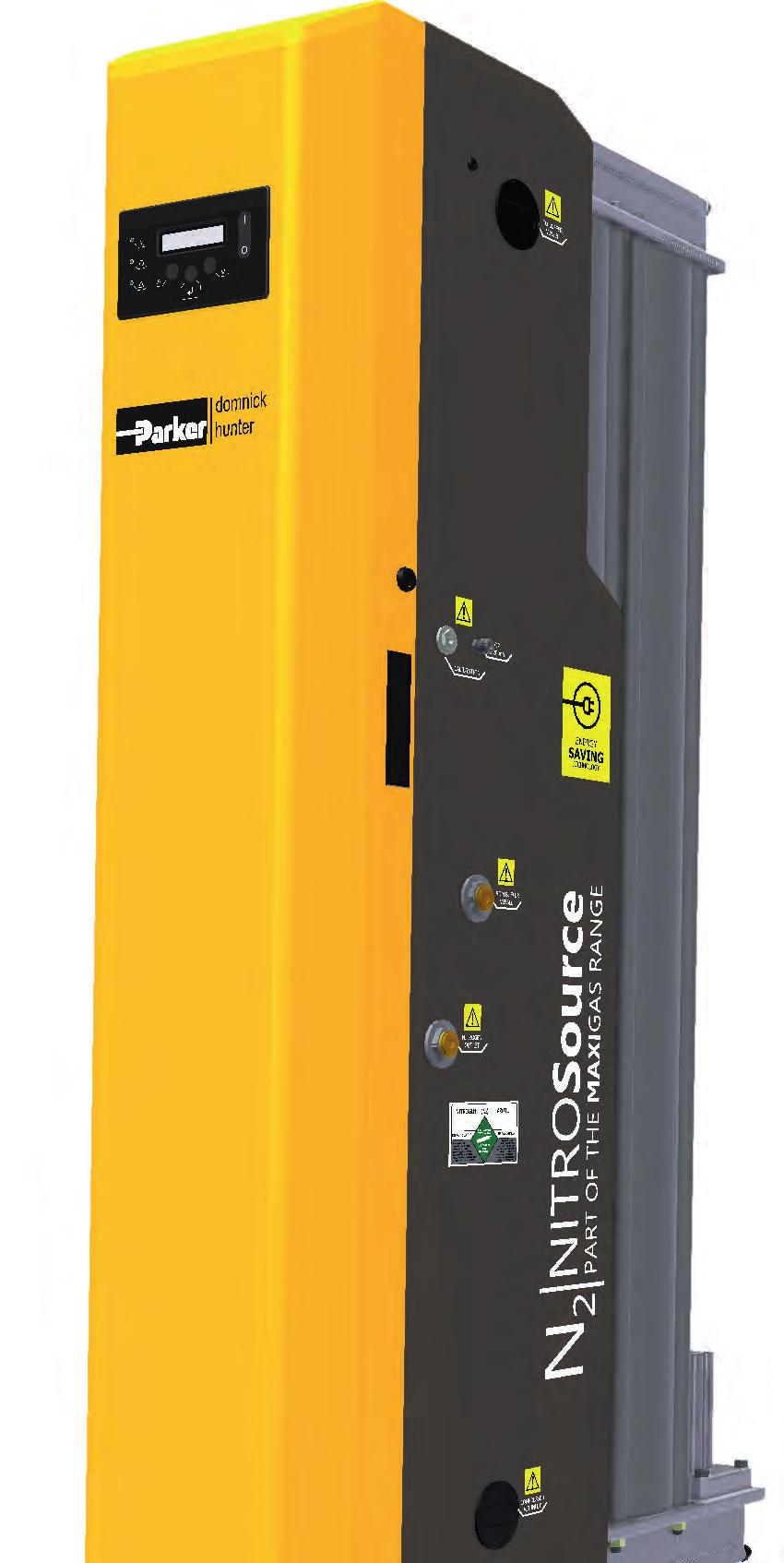
74 INDUSTRIAL GAS GENERATORS NITROSOURCE NITROSource PSA Nitrogen Gas Generator Advanced technology nitrogen gas generator for industry leading performance; a source of increased productivity, sustainability and profitability. NITROSource provides nitrogen gas of 95% to % equivalent nitrogen purity. The NITROSource nitrogen gas generators' unique design and advanced energy saving technology means less compressed air is needed to generate more nitrogen than any other gas generator currently available. Supported by substantially lower servicing costs, reduced downtime and a longer working life than comparable nitrogen generators, NITROSource offers the most cost-efficient nitrogen supply available; significantly more affordable and safer than traditional delivery methods of supply, such as gas cylinders and mini bulk storage. Diagrams: NITROSOURCE H H D W D 73
75 Product Selection Performance data is based on 7 bar g air inlet pressure and 20 C - 25 C ambient temperature. Consult Parker for performance under specific conditions. Nitrogen Flow Rates m 3 /hr vs Purity (oxygen content) 5 ppm 10ppm 50ppm 100ppm 250ppm 500ppm 0.10% 0.40% 0.50% 1% 2% 3% 4% 5% N2-20P N2-25P N2-35P N2-45P N2-55P N2-60P N2-65P N2-75P N2-80P m 3 reference standard 20 C, 1013 millibar(a), 0% relative water vapour pressure. Inlet Parameters Inlet Air Quality ISO : 2010 Class (2.2.1 with high oil vapour content) Inlet Air Pressure Range 5-13 bar g Electrical Parameters Generator Supply /- 10% Vac 50/60Hz Generator Power 55 W INDUSTRIAL GAS GENERATORS NITROSOURCE Fuse 3.15 A (Anti Surge (T), 250v, 5 x 20mm HBC, Breaking Capacity 250v, IEC 60127, UL R/C Fuse) Port Connections Air Inlet N 2 Outlet to Buffer N 2 Inlet from Buffer N 2 Outlet G1 G1 G½ G½ Weights and Dimensions Height (mm) Width (mm) Depth (mm) Weight (kg) N2-20P N2-25P N2-35P N2-45P N2-55P N2-60P N2-65P N2-75P N2-80P For further product information visit 74
76 Part Numbers - without EST Part Number O 2 Purity Flow Part Numbers - with EST Part Number O 2 Purity Flow INDUSTRIAL GAS GENERATORS NITROSOURCE N2-20PBLN Low Purity (%) Low Flow N2-20PALN High Purity (ppm) Low Flow N2-20PXLN Ultra High Purity ( 10ppm) Low Flow N2-25PBLN Low Purity (%) Low Flow N2-25PBMN Low Purity (%) Medium Flow N2-25PALN High Purity (ppm) Low Flow N2-25PXLN Ultra High Purity ( 10ppm) Low Flow N2-35PBLN Low Purity (%) Low Flow N2-35PBMN Low Purity (%) Medium Flow N2-35PALN High Purity (ppm) Low Flow N2-35PXLN Ultra High Purity ( 10ppm) Low Flow N2-45PBLN Low Purity (%) Low Flow N2-45PBMN Low Purity (%) Medium Flow N2-45PALN High Purity (ppm) Low Flow N2-45PXLN Ultra High Purity ( 10ppm) Low Flow N2-55PBLN Low Purity (%) Low Flow N2-55PBMN Low Purity (%) Medium Flow N2-55PBHN Low Purity (%) High Flow N2-55PALN High Purity (ppm) Low Flow N2-55PXLN Ultra High Purity ( 10ppm) Low Flow N2-60PBLN Low Purity (%) Low Flow N2-20PBLY Low Purity (%) Low Flow N2-20PALY High Purity (ppm) Low Flow N2-25PBLY Low Purity (%) Low Flow N2-25PBMY Low Purity (%) Medium Flow N2-25PALY High Purity (ppm) Low Flow N2-35PBLY Low Purity (%) Low Flow N2-35PBMY Low Purity (%) Medium Flow N2-35PALY High Purity (ppm) Low Flow N2-45PBLY Low Purity (%) Low Flow N2-45PBMY Low Purity (%) Medium Flow N2-45PALY High Purity (ppm) Low Flow N2-55PBLY Low Purity (%) Low Flow N2-55PBMY Low Purity (%) Medium Flow N2-55PBHY Low Purity (%) High Flow N2-55PALY High Purity (ppm) Low Flow N2-60PBLY Low Purity (%) Low Flow N2-60PBMY Low Purity (%) Medium Flow N2-60PBHY Low Purity (%) High Flow N2-60PALY High Purity (ppm) Low Flow N2-60PAMY High Purity (ppm) Medium Flow N2-65PBLY Low Purity (%) Low Flow N2-60PBMN Low Purity (%) Medium Flow N2-60PBHN Low Purity (%) High Flow N2-60PALN High Purity (ppm) Low Flow N2-60PAMN High Purity (ppm) Medium Flow N2-60PXLN Ultra High Purity ( 10ppm) Low Flow N2-65PBLN Low Purity (%) Low Flow N2-65PBMN Low Purity (%) Medium Flow N2-65PBHN Low Purity (%) High Flow N2-65PALN High Purity (ppm) Low Flow N2-65PAMN High Purity (ppm) Medium Flow N2-65PXLN Ultra High Purity ( 10ppm) Low Flow N2-75PBLN Low Purity (%) Low Flow N2-75PBMN Low Purity (%) Medium Flow N2-75PBHN Low Purity (%) High Flow N2-75PALN High Purity (ppm) Low Flow N2-75PAMN High Purity (ppm) Medium Flow N2-75PXLN Ultra High Purity ( 10ppm) Low Flow N2-80PBLN Low Purity (%) Low Flow N2-80PBMN Low Purity (%) Medium Flow N2-80PBHN Low Purity (%) High Flow N2-80PALN High Purity (ppm) Low Flow N2-80PAMN High Purity (ppm) Medium Flow N2-80PXLN Ultra High Purity ( 10ppm) Low Flow N2-65PBMY Low Purity (%) Medium Flow N2-65PBHY Low Purity (%) High Flow N2-65PALY High Purity (ppm) Low Flow N2-65PAMY High Purity (ppm) Medium Flow N2-75PBLY Low Purity (%) Low Flow N2-75PBMY Low Purity (%) Medium Flow N2-75PBHY Low Purity (%) High Flow N2-75PALY High Purity (ppm) Low Flow N2-75PAMY High Purity (ppm) Medium Flow N2-80PBLY Low Purity (%) Low Flow N2-80PBMY Low Purity (%) Medium Flow N2-80PBHY Low Purity (%) High Flow N2-80PALY High Purity (ppm) Low Flow N2-80PAMY High Purity (ppm) Medium Flow 75

77 MIDIGAS PSA Nitrogen Gas Generator The cost-effective, reliable and safe solution for small to medium nitrogen requirements. Utilising PSA technology. MIDIGAS provides nitrogen gas of 95% to % equivalent nitrogen purity. MIDIGAS nitrogen gas generators from Parker domnick hunter produce a totally on-demand nitrogen gas supply from a standard factory compressed air supply; a safe and reliable alternative to delivered gas options. The compact and lightweight modular design provides a consistent and easy to maintain solution for low to medium flow rate on-site gas requirements. When maintained in-line with Parker domnick hunter s recommendations, MIDIGAS will offer in excess of 10 years service life from the Carbon Molecular Sieve (CMS), the material that is used to separate nitrogen from compressed air. The MIDIGAS range has been designed to meet multiple industry compliance including CU TR (EAC), CE, UL, CRN and has third party verified FDA Article 21 and European Food and Pharmaceutical approval. MIDIGAS is also exempt from annual PED pressure vessel inspection resulting in minimum disruption to production. Cascading of the generators (multi-banking) is also an option with MIDIGAS meaning that 100% standby is available with the addition of one extra bank, another benefit when considering production uptime. This option also provides ease of upgrade, as and when nitrogen requirements increase. MIDIGAS is the ideal replacement to delivered nitrogen gas, eliminating the issues of administration, logistics and the potential risk of running out of gas associated with high pressure cylinders, liquid mini tanks or bulk storage vessels. INDUSTRIAL GAS GENERATORS MIDIGAS PSA Diagrams: MIDGAS4 H H D W D For further product information visit 76
78 Product Selection Performance data is based on 7 bar g (100 psi g) air inlet pressure and 20 C - 25 C (66 F - 77 F) ambient temperature. Consult Parker for performance under other specific conditions. INDUSTRIAL GAS GENERATORS MIDIGAS PSA MIDIGAS2 MIDIGAS4 MIDIGAS6 Outlet Pressure Nitrogen Flow Rates m 3 /hr vs Purity (oxygen content) Unit 10ppm 100ppm 250ppm 500ppm 0.1% 0.5% 1% 2% 3% 4% 5% m 3 /hr cfm m 3 /hr cfm m 3 /hr cfm bar g psi g m 3 reference standard = 20 C, 1013 millibar(a), 0% relative water vapour pressure. Inlet Parameters Inlet Air Quality Inlet Air Pressure Range Electrical Parameters Supply Voltage Power ISO :2010 Class (2.2.1 with high oil vapour content) 6-13 bar g psi g 115 / 230 ±10% V ac 50/60Hz 80 W Fuse 3.15A (Anti Surge (T), 250v, 5 x 20mm HBC, Breaking Capacity 250v, UL Listed) Port Connections Air Inlet N 2 Outlet to Buffer N 2 Inlet from Buffer N 2 Outlet G½ G½ G½ G½ Weights and Dimensions Height (H) Width (W) Depth (D) Weight mm in mm in mm in kg lb MIDIGAS MIDIGAS MIDIGAS
79 Part Numbers Part Number MIDIGAS 2 without analyser ppm MIDIGAS 2 O 2 analyser ppm MIDIGAS 2 without analyser % MIDIGAS 2 O 2 analyser % MIDIGAS 2 O 2 analyser % high p MIDIGAS 4 O 2 analyser ppm MIDIGAS 4 without analyser % MIDIGAS 4 O 2 analyser % MIDIGAS 4 without analyser % high p MIDIGAS 4 O 2 analyser % high p MIDIGAS 6 O 2 analyser ppm MIDIGAS 6 without analyser % MIDIGAS 6 O 2 analyser % MIDIGAS 6 O 2 analyser % high p MIDIGAS2NCALN MIDIGAS2NCALA MIDIGAS2NCBLN MIDIGAS2NCBLA MIDIGAS2NCBHA MIDIGAS4NCALA MIDIGAS4NCBLN MIDIGAS4NCBLA MIDIGAS4NCBHN MIDIGAS4NCBHA MIDIGAS6NCALA MIDIGAS6NCBLN MIDIGAS6NCBLA MIDIGAS6NCBHA INDUSTRIAL GAS GENERATORS MIDIGAS PSA For further product information visit 78

80 INDUSTRIAL GAS GENERATORS SMARTFLUXX SmartFluxx Nitrogen Gas Membrane Modules SmartFluxx design optimizes highest nitrogen capacity and lowest feed-air consumption, keeping the modules the smallest available on the market. SmartFluxx provides nitrogen gas of 90% to 99.5% equivalent nitrogen purity. Parker hollow-fibre membrane modules produce nitrogen gas from compressed air to offer a cost-effective, reliable and safe solution to on-site nitrogen gas generation. SmartFluxx nitrogen membrane modules are manufactured with a life-expectancy of over 10 years, with no performance decrease over time due to fibre ageing during the manufacturing process. More nitrogen per fibre is produced from Parker hollow fibre membranes than any other in the world, together with the lowest module pressure drop, meaning fewer membranes are needed per nitrogen system. Gas is generated via a low pressure standard industrial compressor resulting in operational energy savings. The correct purity is available instantly as there is no need to heat up the membrane to open the polymer structure, further reducing the energy consumption, resulting in reduced CO 2 emissions. SmartFluxx offers flexible mounting solutions, a small system footprint and no serviceable parts, meaning it operates maintenance free. 79
81 Performance Data SA604 Feed-air Consumption SA708 Feed-air Consumption SA1508 Feed-air Consumption SA1508SS Feed-air Consumption Flow Rates m 3 /hr Max. Min. Max. Temperature Temperature Operating Pressure C F C F bar g psi g bar g psi g bar g psi g bar g psi g bar g psi g bar g psi g bar g psi g bar g psi g INDUSTRIAL GAS GENERATORS SMARTFLUXX SA15020 Feed-air Consumption bar g psi g bar g psi g m 3 /hr refers to conditions at 1013 mbar(a) and 20 C at 7 bar g Weights, Dimensions and Connections Connections Height (H) Width (W) Depth (D) Weight Feed-air Nitrogen Oxygen mm in mm in mm in kg lbs SA604 G ⅜" G ⅜" G ⅜" SA708 G ¾" G ¾" G1" SA1508 G ¾" G ¾" G1" SA1508SS G ¾" G ¾" G1" SA15020 G 2½" G 2½" 3.9" For further product information visit 80

82 INDUSTRIAL GAS GENERATORS HIFLUXX HiFluxx Nitrogen Gas Membrane Modules Membrane modules for producing nitrogen gas at pressures up to 13 bar g from a standard compressed air supply. HiFluxx provides nitrogen gas of 95% to 99.5% equivalent nitrogen purity. Nitrogen is used as a clean, dry, inert gas primarily for removing oxygen from products and/or processes. Parker modules can be built into a custom-made nitrogen generator or can be integrated with your (production) process to provide an on-demand, continuous source of nitrogen gas. This nitrogen gas can be used in a wide range of industries including food, beverage, pharmaceutical, laboratory, chemical, heat treatment, electronics, transportation, oil and gas, mining and marine. Performance Data Flow Rates m 3 /hr Max. Operating Pressure Min. Temperature Max. Temperature C F C F ST304 Feed-air Consumption DT304 Feed-air Consumption bar g psi g bar g psi g bar g psi g bar g psi g
83 Performance Data TT304 Feed-air Consumption ST504 Feed-air Consumption ST604 Feed-air Consumption DT604 Feed-air Consumption TT604 Feed-air Consumption ST608 Feed-air Consumption ST6010 Feed-air Consumption ST1506 Feed-air Consumption DT Feed-air Consumption ST1508 Feed-air Consumption ST1508SS Feed-air Consumption ST Feed-air Consumption Flow Rates m 3 /hr Max. Operating Pressure Min. Temperature Max. Temperature C F C F bar g psi g bar g psi g bar g psi g bar g psi g bar g psi g bar g psi g bar g psi g bar g psi g bar g psi g bar g psi g bar g psi g bar g psi g bar g psi g bar g psi g bar g psi g bar g psi g bar g psi g bar g psi g bar g psi g bar g psi g bar g psi g bar g psi g bar g psi g bar g psi g INDUSTRIAL GAS GENERATORS HIFLUXX m 3 /hr refers to conditions at 1013 mbar(a) and 20 C at 7 bar g For further product information visit 82
84 Weights, Dimensions and Connections INDUSTRIAL GAS GENERATORS HIFLUXX Connections Height (H) Width (W) Depth (D) Weight Feed-air Nitrogen Vent mm inch mm inch mm inch kg ST304 G ⅜" G ⅜" G ⅜" DT304 G ⅜" G ⅜" G ⅜" TT304 G ⅜" G ⅜" G ⅜" ST504 G ⅜" G ⅜" G ⅜" ST604 G ⅜" G ⅜" G ⅜" DT604 G ⅜" G ⅜" G ⅜" TT604 G ⅜" G ⅜" G ⅜" ST608 G ¾" G ¾" G1" ST6010 G1" G1" G1" ST1506 G ¾" G ¾" G1" DT (<8 bar g) G ¾" G ¾" G1" DT (9-13 bar g) G ¾" G ¾" 2x G1" ST1508 G ¾" G ¾" G1" DT1508SS G ¾" G ¾" 2x G1" ST G2 ⅜" G2 ⅜" 100mm

85 Piccolo Nitrogen Gas Membrane Module Small flow nitrogen membrane module, Piccolo provides nitrogen gas of 95% to 98% equivalent nitrogen purity. Nitrogen is used as a clean, dry, inert gas primarily for removing oxygen from products and/or processes. Parker modules can be built into a custom-made nitrogen generator or can be integrated with your (production) process to provide an on-demand, continuous source of nitrogen gas. This nitrogen gas can be used in a wide range of industries including food, beverage, pharmaceutical, laboratory, chemical, heat treatment, electronics, transportation, oil and gas, mining and marine. Piccolo Nitrogen Gas Membrane Modules are capable of producing nitrogen gas for applications requiring small flow with low purity, 95 to 98%. Flow rates range between bar g for 98% to bar g for 95%. INDUSTRIAL GAS GENERATORS PICCOLO 243 Performance Data Flow Rates m 3 /hr Max. Operating Pressure Min. Temperature Max. Temperature bar g C C Piccolo m 3 /hr refers to conditions at 1013 mbar(a) and 20 C at 7 bar g Weights, Dimensions and Connections Connection Height (H) Width (W) Weight Inlet Outlet mm mm kg Piccolo 243 G ⅛" G ⅛" Note Parker membrane systems produce both nitrogen and oxygen enriched air. Nitrogen enriched air can cause suffocation and oxygen enriched air causes increased fire hazards. The oxygen enriched air is available at ambient pressure and pressure build-up of enriched oxygen at the outlet must be prevented, otherwise a serious (reversible) decrease in performance will result. The nitrogen enriched air produced should be treated as pressurised air. For further product information visit 84


86 ADSORPTION FOCUSED ON ADSORPTION Parker are world leaders in compressed air drying. Our range of adsorption dryers is built on unrivalled engineering expertise, and specified with a host of innovative technology and features. Our mission is to deliver 100% validated air quality together with world-leading standards of efficiency and cost-effectiveness. Using our advanced desiccant drying process, we offer comprehensive adsorption solutions for every system, from compressor room to in-line and point-of-use applications providing optimum performance, reliability and ease of use across the range of flow rates and dewpoints. Equipment includes a complete range of heatless dryers (including oil free) and vacuum regenerated dryers. Whatever the application, Parker adsorption solutions are always designed to deliver maximum productivity, total peace of mind and increased economy for industrial users all with the reassurance of Parker engineering excellence. OFAS CDAS KE-MT


87 ADSORPTION MX Series
88 DRYER SELECTION DRYER SELECTION Compressed air dryers are installed to reduce the amount of water vapour in compressed air. To ensure consistent outlet dewpoint, dryers must be sized for the maximum amount of water vapour in the compressed air system (worst case conditions). Water vapour content is highest when system pressure is lowest, system temperature is highest and air flow (usage) is at maximum. In the first instance, dryer selection should be carried out using the Parker sizing and selection software. If selection software is unavailable, correction factors should be applied to the dryer flow rates shown within this document. Apply correction factors if the minimum operating parameters are different to the reference conditions shown. DRYER SELECTION EXAMPLE Maximum Inlet Flow Rate 1500 m³/hr Minimum Temperature 10 C Minimum Inlet Pressure 8.3 bar g Thread Type Required BSPP Maximum Temperature 40 C Maximum Ambient Temperature 30 C Controller Required Energy Management System Required Smart Yes Dewpoint of Compressed Air -40 C 1. Select an appropriate dryer range from the flow rate tables Dryer ranges providing -20 C PDP / -40 C PDP / -70 C PDP Heatless Flows (m³/hr) Flows (cfm) MiDAS - DAS MIDI - DME CDAS HL OFAS HL MX 102c K-MT K-MT Low Energy Dryers Flows (m³/hr) Flows (cfm) MXLE 102c Antares ATT WVM Ensure the maximum and minimum operating temperatures and pressure are within the operational parameters of the dryer range 3. Select the correction factor for maximum inlet temperature from the CFIT table Maximum Inlet Temperature C F Correction Factor Correction Factor for 40 C =
89 4. Select the correction factor for maximum ambient temperature Maximum Ambient Temperature C F Correction Factor Correction Factor for 30 C = Select the correction factor for minimum inlet pressure from the CFP table Minimum Inlet Pressure Correction Factor for 8.3 bar g = 0.89 bar g psi g Correction Factor DRYER SELECTION 6. Select the correction factor for the required dewpoint from the CFD Maximum Inlet Temperature C F Correction Factor Correction Factor for -40 C PDP = 1.00 Important notes: Temperature: Always round up to the next correction factor i.e. for 38 C select the correction factor for 40 C Pressure: Always round down to nearest factor i.e. for 8.3 bar g select the correction factor for 8 bar g Flow: The dryer selected must have a flow rate equal to or greater than the minimum filtration capacity 7. Calculate the minimum drying capacity Minimum drying capacity = Compressed air flow rate x CFIT x CFAT x CFP x CFD Minimum drying capacity = 1500 m³/hr x 1.04 x 1.00 x 0.89 x 1.00 = 1388 m³/hr Using the minimum drying capacity, select an MX dryer model from the literature flow rate tables selected = MX106 m 3 /hr Flow cfm MX 102C MX 103C Single Bank MX MX MX MX MX MX Which controller is required? Smart controller is required therefore model selected = MXS Is DDS Energy Management System required? DDS Energy Management system is required therefore model selected = MXS106DS For further product information visit 88
90 COMPRESSED AIR REGENERATIVE DESICCANT DRYERS

91 Compressed Air Regenerative Desiccant Dryers Using the adsorption method, Parker regenerative desiccant dryers remove unwanted moisture from compressed air. Water vapour molecules are attracted and retained when the air is passed over a regenerative desiccant material a drying process designed to provide reliable and cost-effective water vapour removal. COMPRESSED AIR REGENERATIVE DESICCANT DRYERS

92 COMPRESSED AIR REGENERATIVE DESICCANT DRYERS PNEUDRI MIDAS Diagrams: DAS1-7 H PNEUDRI MiDAS Small Flow Heatless Compressed Air Dryer Small flow compressed air dryers providing pressure dewpoints of -70 C and -40 C with flow rates up to 34 7 bar g. Compressed air contamination problems can be simply avoided by installing a Parker domnick hunter PNEUDRI MiDAS high efficiency compressed air dryer package fitted with integrated high efficiency filtration. The packages are suitable for use with any compressor type and are suited to point of use applications. Parker domnick hunter's PNEUDRI MiDAS heatless compressed air dryers provide clean, oil-free and dry compressed air in accordance with all editions of ISO8573-1, the international standard for compressed air quality. They are energy efficient and can provide pressure dewpoints of -70 C and -40 C with flow rates up to 34 7 bar g (100 psi g). Clean, dry air improves production efficiency and reduces maintenance costs and downtime. Only an adsorption dryer can provide the highest levels of dry compressed air. W D Dryer Performance Dewpoint (Standard) ISO8573-1:2010 Classification (Standard) Dewpoint (Option 1) C F C F ISO8573-1:2010 Classification (Option 1) MiDAS Class Class ISO Classifications when used with Parker domnick hunter OIL-X pre / post filtration 91
93 Technical Data Min. Operating Pressure Max. Operating Pressure Min. Operating Temperature Max. Operating Temperature Max. Ambient Temperature Electrical Supply (Standard) Electrical Supply (Optional) Filter Thread Connections bar g psi g bar g psi g C F C F C F db(a) DAS Flow Rates Port Connection BSPP or NPT Product Selection and Correction Factors 230 / 1ph / 50Hz Inlet Flow Rate 115 / 1ph / 60Hz L/s m 3 /min m 3 /hr cfm DAS 1 3 / DAS 2 3 / DAS 3 3 / DAS 4 3 / DAS 5 3 / DAS 6 3 / DAS 7 3 / Stated flows are for operation at 7 bar (g) (102 psi g) with reference to 20 C, 1 bar (a), 0% relative water vapour pressure. For flows at other pressures, apply the correction factors shown below. Noise Level BSPP or NPT <75 For correct operation, compressed air dryers must be sized using for the minimum pressure, maximum temperature and maximum flow rate of the installation. To select a dryer, first calculate the MDC (Minimum Drying Capacity) using the formula below then select a dryer from the flow rate table above with a flow rate equal to or above the MDC. Minimum Drying Capacity = System Flow x CFIT x CFAT x CFP x CFD CFIT - Correction Factor Maximum Inlet Temperature Maximum Inlet Temperature C F Correction Factor CFAT - Correction Factor Maximum Ambient Temperature Maximum Ambient Temperature C F Correction Factor CFP - Correction Factor Minimum Inlet Pressure COMPRESSED AIR REGENERATIVE DESICCANT DRYERS PNEUDRI MIDAS Minimum Inlet Pressure bar g psi g Correction Factor CFD - Correction Factor Dewpoint Maximum Inlet Temperature C F Correction Factor For further product information visit 92
94 Controller Functions Controller Function COMPRESSED AIR REGENERATIVE DESICCANT DRYERS PNEUDRI MIDAS Power On Indication Visual Fault Indication Recommended Filtration Dewpoint Display DDS - Energy Saving Technology Filter Service Indicator Dryer Service Indicator DAS *PNEUDRI MiDAS dryers include integral high efficiency pre and general purpose dust filters. Part Numbers Filter Port Connection BSPP or NPT Inlet General Purpose Pre-filter Inlet High Efficiency Filter Fault Relay: Power Loss Dewpoint Alarm Sensor Failure 4-20mA Dewpoint Re-transmission Outlet Dust Filter DAS1 3 /8" AO005B FX Integrated* Integrated* DAS2 3 /8" AO005B FX Integrated* Integrated* DAS3 3 /8" AO005B FX Integrated* Integrated* DAS4 3 /8" AO005B FX Integrated* Integrated* DAS5 3 /8" AO005B FX Integrated* Integrated* DAS6 3 /8" AOP0010B F Integrated* Integrated* DAS7 3 /8" AOP0010B F Integrated* Integrated* Weights and Dimensions Port Connection Dimensions Height (H) Width (W) Depth (D) = B (BSPT) or N (NPT) Weight mm ins mm ins mm ins kg lbs DAS1 3 /8" DAS2 3 /8" DAS3 3 /8" DAS4 3 /8" DAS5 3 /8" DAS6 3 /8" DAS7 3 /8" DAS -40 C 230V /1ph/50Hz DAS -40 C 115V /1ph/60Hz DAS1 DAS2 DAS3 DAS4 DAS5 DAS6 DAS7 DAS CSA DAS CSA DAS CSA DAS CSA DAS CSA DAS CSA DAS CSA For a -70 C PDP application please consult the factory. 93

95 PNEUDRI MIDIplus Medium Flow Heatless Compressed Air Dryer Medium flow compressed air dryers providing pressure dewpoints of -70 C and -40 C with flow rates up to bar g. Compressed air contamination problems can be simply avoided by installing a Parker domnick hunter PNEUDRI MIDIplus high efficiency compressed air dryer package fitted with OIL-X EVOLUTION filtration. The packages are suitable for use with any compressor type and are suited to point-of-use applications. Parker domnick hunter's PNEUDRI MIDIplus heatless compressed air dryers provide clean, oil-free and dry compressed air in accordance with all editions of ISO8573-1, the international standard for compressed air quality. They are energy efficient and can provide pressure dewpoints of -70 C and -40 C with flow rates up to bar g (100 psi g). Clean, dry air improves production efficiency and reduces maintenance costs and downtime. Diagrams: DME 012 H Zander COMPRESSED AIR REGENERATIVE DESICCANT DRYERS PNEUDRI MIDIPLUS W D Dryer Performance Dewpoint (Standard) ISO :2010 Classification (standard) ºC ºF ºC ºF Dewpoint (Option 1) ISO :2010 Classification (Option 1) DME Class Class 1 DMOP Class Class 1 For further product information visit 94
96 Technical Data COMPRESSED AIR REGENERATIVE DESICCANT DRYERS PNEUDRI MIDIPLUS Min. Operating Max. Operating Min. Operating Max. Operating Max. Ambient Noise Electrical Electrical Pressure Pressure Temperature Temperature Temperature Thread Level Supply Supply Connection bar g psi g bar g psi g C F C F C F (Standard) (Optional) db(a) DME Flow Rates 230V 1ph 50/60Hz 110V 1ph 50/60Hz BSPP or NPT Port Connection¹ L/S m 3 /min m 3 /hr cfm DME012 / DMO012P G 3 / Stated flows are for operation at 7 bar g (100 psi g) with reference to 20 C, 1 bar a, 0% relative water vapour pressure. For flows at other pressures, apply the correction factors shown. 1 BSPP or NPT threads available. Please state at time of ordering. CFT Correction Factor Temperature Maximum Inlet Temperature C F CFT CFP Correction Factor Pressure Minimum Inlet Pressure bar g psi g CFP CFD Correction Factor Dewpoint Required Dewpoint Controller Functions Controller Options PDP C PDP F CFD Power On Indication Fault Indication Display Fault Condition Values Service Interval Indication Function Service Contdown Timers Configurable Alarm Settings Remote Volt Free Alarm Contacts DME (Electronic control) Filter Service Timer <75 DDS Energy Management System DME DDS DM0P Please state dewpoint at the time of ordering Recommended Filtration Filter Port Connection BSPT or NPT Inlet General Purpose Pre-filter Inlet High Efficiency Filter Outlet Dust Filter DME012 / DMO012P 3 /4" -- AAP020D FI AOP020D -MI Weights and Dimensions = B (BSPT) or N (NPT) Port Connection Inlet / Outlet Dimensions Weight Height (H) Width (W) Depth (D) mm ins mm ins mm ins kg lbs DME012 3 /4"
97 Part Numbers Part Number DME012BFK DME012BFK-70 DME012DSBFK DME012DSBFK-70 DMP012-ATEX COMPRESSED AIR REGENERATIVE DESICCANT DRYERS PNEUDRI MIDIPLUS For further product information visit 96


.")

98 COMPRESSED AIR REGENERATIVE DESICCANT DRYERS CDAS HL Diagrams: CDAS HL50-70 H Zander CDAS HL Medium Flow Heatless Compressed Air Dryer System Medium flow compressed air treatment systems providing pressure dewpoints of -70 C, -40 C or -20 C at flow rates up to bar g. Suitable for all industrial compressed air applications. Compressed air contamination problems can be simply avoided by installing a Parker Zander CDAS HL Clean Dry Air System (including OIL-X filtration). The fully integrated heatless compressed air dryer and filtration packages are suitable for use with any compressor type and can be installed in the compressor room or at point-of-use. Parker Zander's CDAS HL Clean Dry Air Systems provide clean, dry compressed air in accordance with all editions of ISO8573-1, the international standard for compressed air quality. They are energy efficient and can provide pressure dewpoints of -70 C, -40 C or -20 C with flow rates up to bar g (102 psi g). Clean, dry air improves production efficiency and reduces maintenance costs and downtime. Many products claim to provide this, however only CDAS HL Clean Dry Air Systems provide the highest levels of dry compressed air with validated performance. CDAS HL75-85 H W D W D Dryer Performance Dewpoint (Standard) ISO8573-1:2010 Classification (Standard) Dewpoint (Option 1) ISO8573-1:2010 Classification (Option 1) Dewpoint (Option 2) C F C F C F ISO8573-1:2010 Classification (Option 2) CDAS HL Class Class Class ISO Classifications when used with Parker domnick hunter OIL-X pre / post filtration 97
99 Technical Data CDAS HL Flow Rates Min. Operating Pressure Max. Operating Pressure Min. Operating Temperature Product Selection and Correction Factors Max. Operating Temperature Max. Ambient Temperature Electrical Supply (Standard) Electrical Supply (Optional) Filter Thread Connections bar g psi g bar g psi g C F C F C F db(a) Port Connection BSPP or NPT V 1ph 50/60Hz Inlet Flow Rate For correct operation, compressed air dryers must be sized using for the minimum pressure, maximum temperature and maximum flow rate of the installation. To select a dryer, first calculate the MDC (Minimum Drying Capacity) using the formula below then select a dryer from the flow rate table above with a flow rate equal to or above the MDC. Minimum Drying Capacity = System Flow x CFIT x CFAT x CFP x CFD Noise Level 24V DC BSPP or NPT <75 L/s m 3 /min m 3 /hr cfm CDAS HL 50 1 / CDAS HL 55 1 / CDAS HL 60 1 / CDAS HL 65 1 / CDAS HL 70 3 / CDAS HL CDAS HL CDAS HL / CFIT - Correction Factor Maximum Inlet Temperature Maximum Inlet Temperature C F Correction Factor CFAT - Correction Factor Maximum Ambient Temperature Maximum Ambient Temperature C F COMPRESSED AIR REGENERATIVE DESICCANT DRYERS CDAS HL Correction Factor CFP - Correction Factor Minimum Inlet Pressure Minimum Inlet Pressure bar g psi g Correction Factor CFD - Correction Factor Dewpoint Maximum Inlet Temperature C F Correction Factor For further product information visit 98
100 Controller Functions Controller Function COMPRESSED AIR REGENERATIVE DESICCANT DRYERS CDAS HL Power On Indication Included Filtration Visual Fault Indication Dewpoint Display Port Connection BSPP or NPT EST - Energy Saving Technology Inlet General Purpose Pre-filter Filter Service Indicator Inlet High Efficiency Filter Dryer Service Indicator Fault Relay: Power Loss Dewpoint Alarm Sensor Failure Oil Vapour Removal Filter 4-20mA Dewpoint Re-transmission CDAS HL Outlet Dust Filter CDAS HL 50 1 /2 AOP015CGFI AAP015CGFI - AOP015CGMI CDAS HL 55 1 /2 AOP015CGFI AAP015CGFI - AOP015CGMI CDAS HL 60 1 /2 AOP020CGFI AAP020CGFI - AOP020CGMI CDAS HL 65 1 /2 AOP020CGFI AAP020CGFI - AOP020CGMI CDAS HL 70 3 /4 AOP025DGFI AAP025DGFI - AOP025DGMI CDAS HL 75 1 AOP025EGFI AAP025EGFI - AOP025EGMI CDAS HL 80 1 AOP025EGFI AAP025EGFI - AOP025EGMI CDAS HL /2 AOP030GGFI AAP030GGFI - AOP030GGMI Weights and Dimensions Port Connection Inlet / Outlet Dimensions Height (H) Width (W) Depth (D) Weight mm ins mm ins mm ins kg lbs General Purpose Coalescing Filter Inlet High Efficiency Coalescing Filter Outlet General Purpose Dry Particulate Filter CDAS HL 50 ½ AOP015C AAP015C AOP015C CDAS HL 55 ½ AOP015C AAP015C AOP015C CDAS HL 60 ½ AOP020C AAP020C AOP020C CDAS HL 65 ½ AOP020C AAP020C AOP020C CDAS HL 70 3/ AOP025D AAP025D AOP025D CDAS HL AOP025E AAP025E AOP025E CDAS HL AOP025E AAP025E AOP025E CDAS HL 85 1½ AOP030G AAP030G AOP030G Part Numbers -20 C PDP / -40 C PDP BSPP -70 C PDP BSPP CDAS HL 50 CDASHL050-40G16AE CDASHL050-70G16AE CDAS HL 55 CDASHL055-40G16AE CDASHL055-70G16AE CDAS HL 60 CDASHL060-40G16AE CDASHL060-70G16AE CDAS HL 65 CDASHL065-40G16AE CDASHL065-70G16AE CDAS HL 70 CDASHL070-40G16AE CDASHL070-70G16AE CDAS HL 75 CDASHL075-40G16AE CDASHL075-70G16AE CDAS HL 80 CDASHL080-40G16AE CDASHL080-70G16AE CDAS HL 85 CDASHL085-40G16AE CDASHL085-70G16AE 99

.")


101 Zander OFAS HL Medium Flow Oil Free Heatless Compressed Air Dryer System Medium flow compressed air treatment systems with oil vapour removal, providing ISO Class 0 air at flow rates up to bar g. Suitable for all industrial compressed air applications. Compressed air contamination problems can be simply avoided by installing a Parker Zander OFAS HL Oil Free Air System fitted (including OIL-X filtration). The fully integrated heatless compressed air dryer and filtration packages are suitable for use with any compressor type and can be installed in the compressor room or at point-of-use. Fitted with a third adsorbent column for oil vapour removal, Parker Zander's OFAS HL Clean Dry Air Systems have been third party validated by Lloyds Register to provide ISO Class 0, with respect to total oil from both oil lubricated and oil free compressors, ensuring the highest quality air at the point-of-use for critical applications. Clean, dry, oil free air improves production efficiency and reduces maintenance costs and downtime. Only OFAS HL Oil Free Air Systems can provide the highest levels of clean, dry, oil free compressed air with validated performance. Diagrams: OFAS HL50-55 H H OFAS HL60-70 OFAS HL50-55 H COMPRESSED AIR REGENERATIVE DESICCANT DRYERS OFAS HL W D W D W D Dryer Performance Dewpoint (Standard) ISO8573-1:2010 Classification (Standard) Dewpoint (Option 1) ISO8573-1:2010 Classification (Option 1) Dewpoint (Option 2) C F C F C F ISO8573-1:2010 Classification (Option 2) CDAS HL Class Class Class ISO Classifications when used with Parker domnick hunter OIL-X pre / post filtration For further product information visit 100
102 Technical Data COMPRESSED AIR REGENERATIVE DESICCANT DRYERS OFAS HL OFAS HL Flow Rates Min. Operating Pressure Max. Operating Pressure Min. Operating Temperature Product Selection and Correction Factors Max. Operating Temperature Max. Ambient Temperature Electrical Supply (Standard) Electrical Supply (Optional) Filter Thread Connections bar g psi g bar g psi g C F C F C F db(a) Port Connection BSPP or NPT V 1ph 50/60Hz Inlet Flow Rate For correct operation, compressed air dryers must be sized using for the minimum pressure, maximum temperature and maximum flow rate of the installation. To select a dryer, first calculate the MDC (Minimum Drying Capacity) using the formula below then select a dryer from the flow rate table above with a flow rate equal to or above the MDC. Minimum Drying Capacity = System Flow x CFIT x CFAT x CFP x CFD Noise Level 24V DC BSPP or NPT <75 L/s m 3 /min m 3 /hr cfm OFAS HL 50 1 / OFAS HL 55 1 / OFAS HL 60 1 / OFAS HL 65 1 / OFAS HL 70 3 / OFAS HL OFAS HL OFAS HL / Stated flows are for operation at 7 bar (g) (102 psi g) with reference to 20 C, 1 bar (a), 0% relative water vapour pressure. For flows at other pressures, apply the correction factors shown below. CFIT - Correction Factor Maximum Inlet Temperature Maximum Inlet Temperature C F Correction Factor CFAT - Correction Factor Maximum Ambient Temperature Maximum Ambient Temperature C F Correction Factor CFP - Correction Factor Minimum Inlet Pressure Minimum Inlet Pressure bar g psi g Correction Factor CFD - Correction Factor Dewpoint Maximum Inlet Temperature C F Correction Factor
103 Controller Functions Controller Function Power On Indication Included Filtration Visual Fault Indication Dewpoint Display Port Connection BSPP or NPT EST - Energy Saving Technology Inlet General Purpose Pre-filter Filter Service Indicator Inlet High Efficiency Filter Dryer Service Indicator Fault Relay: Power Loss Dewpoint Alarm Sensor Failure Oil Vapour Removal Filter 4-20mA Dewpoint Re-transmission OFAS HL Outlet Dust Filter OFAS HL 50 1 /2 AOP015CGFI AAP015CGFI Included AOP015CGMI OFAS HL 55 1 /2 AOP015CGFI AAP015CGFI Included AOP015CGMI OFAS HL 60 1 /2 AOP020CGFI AAP020CGFI Included AOP020CGMI OFAS HL 65 1 /2 AOP020CGFI AAP020CGFI Included AOP020CGMI OFAS HL 70 3 /4 AOP025DGFI AAP025DGFI Included AOP025DGMI OFAS HL 75 1 AOP025EGFI AAP025EGFI Included AOP025EGMI OFAS HL 80 1 AOP025EGFI AAP025EGFI Included AOP025EGMI OFAS HL /2 AOP030GGFI AAP030GGFI Included AOP030GGMI Weights and Dimensions Port Connection Inlet / Outlet Dimensions Inlet Outlet Height (H) Width (W) Depth (D) Weight mm ins mm ins mm ins kg lbs General Purpose Coalescing Filter High Efficiency Coalescing Filter General Purpose Dry Particulate Filter OFAS HL 50 ½ AOP015C AAP015C AOP015C OFAS HL 55 ½ AOP015C AAP015C AOP015C OFAS HL 60 ½ AOP020C AAP020C AOP020C OFAS HL 65 ½ AOP020C AAP020C AOP020C OFAS HL 70 3/ AOP025D AAP025D AOP025D OFAS HL AOP025E AAP025E AOP025E COMPRESSED AIR REGENERATIVE DESICCANT DRYERS OFAS HL OFAS HL AOP025E AAP025E AOP025E OFAS HL 85 1½ AOP030G AAP030G AOP030G Part Numbers -20 C PDP / -40 C PDP BSPP -70 C PDP BSPP OFAS HL 50 OFASHL050-40G16AE OFASHL050-70G16AE OFAS HL 55 OFASHL055-40G16AE OFASHL055-70G16AE OFAS HL 60 OFASHL060-40G16AE OFASHL060-70G16AE OFAS HL 65 OFASHL065-40G16AE OFASHL065-70G16AE OFAS HL 70 OFASHL070-40G16AE OFASHL070-70G16AE OFAS HL 75 OFASHL075-40G16AE OFASHL075-70G16AE OFAS HL 80 OFASHL080-40G16AE OFASHL080-70G16AE OFAS HL 85 OFASHL085-40G16AE OFASHL085-70G16AE For further product information visit 102
104 COMPRESSED AIR REGENERATIVE DESICCANT DRYERS PNEUDRI MX Diagrams: MX 102c 108 H Zander PNEUDRI MX Large Flow Heatless Compressed Air Dryer Large flow modular compressed air dryers providing pressure dewpoints of -70 C and -40 C with flow rates up to bar g, even greater flow rates can be achieved by multi-banking the dryers. PNEUDRI MX heatless compressed air dryers provide clean, oil-free and dry compressed air in accordance with all editions of ISO8573-1, the international standard for compressed air quality. They are energy efficient and use a modular construction making them less than half the size of conventional dryers. The PNEUDRI MX's modular construction allows greater flexibility, it can be multi-banked to provide extra compressed air drying capacity should demand increase. This distinctive feature allows 100% stand by at a fraction of the cost of a traditional twin tower dryer and also allows individual dryers to be easily isolated for routine service work, whilst maintaining the plants clean, dry air supply. W D Dryer Performance Dewpoint (Standard) ISO8573-1:2010 Classification (Standard) Dewpoint (Option 1) ISO8573-1:2010 Classification (Option 1) Dewpoint (Option 2) C F C F C F ISO8573-1:2010 Classification (Option 2) MX Class Class Class ISO Classifications when used with Parker domnick hunter OIL-X pre / post filtration 103
105 Technical Data MX102c Flow Rates Min. Operating Pressure Max. Operating Pressure Min. Operating Temperature Max. Operating Temperature Max. Ambient Temperature Electrical Supply (Standard) Electrical Supply (Optional) Filter Thread Connections bar g psi g bar g psi g C F C F C F db(a) Port Connection V 1ph 50/60Hz Inlet Flow Rate Noise Level N/A BSPP or NPT <75 L/s m 3 /min m 3 /hr cfm MX 102C MX 103C MX MX / MX / MX / MX / MX / x MX / x MX / x MX / x MX / x MX / x MX / x MX / Stated flows are for operation at 7 bar (g) (102 psi g) with reference to 20 C, 1 bar (a), 0% relative water vapour pressure. For flows at other pressures, apply the correction factors shown below. Product Selection and Correction Factors For correct operation, compressed air dryers must be sized using for the minimum pressure, maximum temperature and maximum flow rate of the installation. To select a dryer, first calculate the MDC (Minimum Drying Capacity) using the formula below then select a dryer from the flow rate table above with a flow rate equal to or above the MDC. Minimum Drying Capacity = System Flow x CFIT x CFAT x CFP x CFD CFIT - Correction Factor Maximum Inlet Temperature Maximum Inlet Temperature C F Correction Factor COMPRESSED AIR REGENERATIVE DESICCANT DRYERS PNEUDRI MX CFAT - Correction Factor Maximum Ambient Temperature Maximum Ambient Temperature C F Correction Factor CFP - Correction Factor Minimum Inlet Pressure Minimum Inlet Pressure bar g psi g Correction Factor CFD - Correction Factor Dewpoint Maximum Inlet Temperature C F Correction Factor For further product information visit 104
106 Controller Functions Controller Function COMPRESSED AIR REGENERATIVE DESICCANT DRYERS PNEUDRI MX Power On Indication Visual Fault Indication Dewpoint Display EST - Energy Saving Technology Filter Service Indicator Important notes regarding the ordering of PNEUDRI MX dryers Dryer Service Indicator MXS Please note that when ordering PNEUDRI MX heatless dryers, the following items must be ordered separately. Dryer model Inlet / outlet flange kit (BSPP or NPT) Pre / post filtration (grades AO / AA/ AO) FCD (flow control device) - only required for multi-bank installations QRV - quick repressurisation valve part number is required for operating pressures above 9 bar g Fault Relay: Power Loss Dewpoint Alarm Sensor Failure 4-20mA Dewpoint Re-transmission MXS DS Option MXA Required Filtration Port Connection BSPP or NPT Inlet General Purpose Pre-filter Inlet High Efficiency Filter Oil Vapour Removal Filter Outlet Dust Filter MX 102C 2" AOP040HGFX AAP040HGFX * AOP040HGMX MX 103C 2" AOP040HGFX AAP040HGFX * AOP040HGMX MX 103 2" AOP040HGFX AAP040HGFX * AOP040HGMX MX /2 AOP045IGFX AAP045IGFX * AOP045IGMX MX /2" AOP050IGFX AAP050IGFX * AOP050IGMX MX /2" AOP050IGFX AAP050IGFX * AOP050IGMX MX /2" AOP055IGFX AAP055IGFX * AOP055IGMX MX /2" AOP055IGFX AAP055IGFX * AOP055IGMX *Note: Technically Oil Free Air to ISO8573-1:2010 Class 0 (<0.003mg/m 3 ) for Total Oil can be easily achieved by selecting an optional OIL-X OVR grade filter (refer to pages 7-8 of this document). Weights and Dimensions Port Connection Dimensions Height (H) Width (W) Depth (D) Weight mm ins mm ins mm ins kg lbs MX 102C 2" MX 103C 2" MX 103 2" MX / MX / MX / MX / MX /
107 Part Numbers -20 and -40 MX -20 and -40 MX DDS -20 and -40 MX Advanced -20 and -40 MXP Pneumatic MXS102C-40BP MXS102CDS-40BP MXA102C-40 MXP102C-40-ATEX MXS103C-40BP MXS103CDS-40BP MXA103C-40 MXP103C-40-ATEX MXS103-40BP MXS103DS-40BP MXA MXP ATEX MXS104-40BP MXS104DS-40BP MXA MXP ATEX MXS105-40BP MXS105DS-40BP MXA MXP ATEX MXS106-40BP MXS106DS-40BP MXA MXP ATEX MXS107-40BP MXS107DS-40BP MXA MXP ATEX MXS108-40BP MXS108DS-40BP MXA MXP ATEX MXS102C-70BP MXS102CDS-70BP MXA102C-70 MXP102C-70-ATEX MXS103C-70BP MXS103CDS-70BP MXA103C-70 MXP103C-70-ATEX MXS103-70BP MXS103DS-70BP MXA MXP ATEX MXS104-70BP MXS104DS-70BP MXA MXP ATEX MXS105-70BP MXS105DS-70BP MXA MXP ATEX MXS106-70BP MXS106DS-70BP MXA MXP ATEX MXS107-70BP MXS107DS-70BP MXA MXP ATEX MXS108-70BP MXS108DS-70BP MXA MXP ATEX COMPRESSED AIR REGENERATIVE DESICCANT DRYERS PNEUDRI MX For further product information visit 106

108 Zander COMPRESSED AIR REGENERATIVE DESICCANT DRYERS PNEUDRI MXLE Diagrams: MXLE102c - MXLE105 SINGLE VACUUM PUMP MXLE106 - MXLE108 DUPLEX VACUUM PUMP PNEUDRI MXLE Large Flow Low Energy Heatless Compressed Air Dryer Large flow low energy modular compressed air dryers providing pressure dewpoints of -70 C and -40 C with flow rates up to bar g, even greater flow rates can be achieved by multi-banking the dryers. The PNEUDRI MXLE ADVANTAGE compressed air dryer has been specifically designed to provide all of the benefits of the PNEUDRI MX heatless adsorption dryer with the additional benefits of lower energy costs and lower environmental impact via its vacuum regeneration method, allowing around 17% more of the generated clean, dry compressed air to be used across the plant. At full load conditions, PNEUDRI MXLE has an average 60% lower energy consumption than a comparative heatless dryer and an average 39% lower energy consumption than a comparative heat regenerative dryer. These energy savings increase in periods of low air demand due to the integrated Energy Management System which is fitted as standard. The modular construction allows greater flexibility; like PNEUDRI MX, models can be multi-banked to provide extra compressed air drying capacity should demand increase. This distinctive feature allows 100% stand by at a fraction of the cost of a traditional twin tower dryer and also allows individual dryers to be easily isolated for routine service work, whilst maintaining the plants clean, dry air supply. The PNUEDRI MXLE also offers the extra security of a full back up mode, and in the unlikely event of a fault occurring with the vacuum pump, the dryer can be operated in full heatless mode to keep the plant operational. DRYER H VACUUM PUMP W H W D D Dryer Performance Dewpoint (Standard) ISO8573-1:2010 Classification (Standard) Dewpoint (Option 1) ISO8573-1:2010 Classification (Option 1) Dewpoint (Option 2) C F C F C F ISO8573-1:2010 Classification (Option 2) MXLE Class Class Class ISO Classifications when used with Parker domnick hunter OIL-X pre / post filtration
109 Technical Data MXLE 102c Flow Rates Min. Operating Pressure Max. Operating Pressure Min. Operating Temperature Product Selection and Correction Factors Max. Operating Temperature Max. Ambient Temperature Electrical Supply (Standard) Electrical Supply (Optional) Filter Thread Connections bar g psi g bar g psi g C F C F C F db(a) Port Connection Inlet Flow Rate L/s m 3 /min m 3 /hr cfm MXLE 102C MXLE 103C MXLE MXLE / MXLE / MXLE / MXLE / MXLE / V +/-10% 3PH 50Hz Stated flows are for operation at 7 bar (g) (102 psi g) with reference to 20 C, 1 bar (a), 0% relative water vapour pressure. For flows at other pressures, apply the correction factors shown below. 460V +/-10% 3PH 60Hz Vacuum Pump kw For correct operation, compressed air dryers must be sized using for the minimum pressure, maximum temperature and maximum flow rate of the installation. To select a dryer, first calculate the MDC (Minimum Drying Capacity) using the formula below then select a dryer from the flow rate table above with a flow rate equal to or above the MDC. Minimum Drying Capacity = System Flow x CFIT x CFAT x CFP x CFD CFIT - Correction Factor Maximum Inlet Temperature Maximum Inlet Temperature Noise Level BSPP <75 kw 50Hz Pump kw 60Hz Pump MXLE 102C MXLE 103C MXLE MXLE MXLE MXLE MXLE MXLE C F Correction Factor CFAT - Correction Factor Maximum Ambient Temperature Maximum Ambient Temperature C F COMPRESSED AIR REGENERATIVE DESICCANT DRYERS PNEUDRI MXLE Correction Factor CFP - Correction Factor Minimum Inlet Pressure Minimum Inlet Pressure bar g psi g Correction Factor CFD - Correction Factor Dewpoint Maximum Inlet Temperature C F Correction Factor
110 Controller Functions Controller Function COMPRESSED AIR REGENERATIVE DESICCANT DRYERS PNEUDRI MXLE Power On Indication Included Filtration Visual Fault Indication Dewpoint Display Port Connection BSPP EST - Energy Saving Technology Inlet General Purpose Pre-filter Filter Service Indicator Inlet High Efficiency Filter Dryer Service Indicator Fault Relay: Power Loss Dewpoint Alarm Sensor Failure Oil Vapour Removal Filter 4-20mA Dewpoint Re-transmission MXLE Outlet Dust Filter MXLE 102C 2 AOP040HGFX AAP040HGFX * AOP040HGMX MXLE 103C 2 AOP040HGFX AAP040HGFX * AOP040HGMX MXLE AOP040HGFX AAP040HGFX * AOP040HGMX MXLE /2 AOP045IGFX AAP045IGFX * AOP045IGMX MXLE /2 AOP050IGFX AAP050IGFX * AOP050IGMX MXLE /2 AOP050IGFX AAP050IGFX * AOP050IGMX MXLE /2 AOP055IGFX AAP055IGFX * AOP055IGMX MXLE /2 AOP055IGFX AAP055IGFX * AOP055IGMX *Note: Technically Oil Free Air to ISO8573-1:2010 Class 0 (<0.003mg/m 3 ) for Total Oil can be easily achieved by selecting an optional OIL-X OVR grade filter (refer to pages 7-8 of this document). Weights and Dimensions Port Connection Dryer Dimensions Height (H) Width (W) Depth (D) Weight mm ins mm ins mm ins kg lbs MXLE102c 2" MXLE103c 2" MXLE103 2" MXLE / MXLE / MXLE / MXLE / MXLE / Vacuum Pump Dimensions Height (H) Width (W) Depth (D) Weight mm ins mm ins mm ins kg lbs MXLE102c MXLE103c MXLE MXLE MXLE MXLE MXLE MXLE Part Numbers -20 C PDP / -40 C PDP BSPP -70 C PDP BSPP 50Hz Vacuum Pump 60Hz Vacuum Pump MXLE102C MXLE102C0 MXLE102C-70 MXLEP2C-E MXLEP2C-E-60 MXLE103C MXLE103C0 MXLE103C-70 MXLEP3C-E MXLEP3C-E-60 MXLE103 MXLE1030 MXLE MXLEP3-E MXLEP3-E-60 MXLE104 MXLE1040 MXLE MXLEP4-E MXLEP4-E-60 MXLE105 MXLE105 MXLE MXLEP5-E MXLEP5-E-60 MXLE106 MXLE106 MXLE MXLEP6-E MXLEP6-E-60 MXLE107 MXLE107 MXLE MXLEP7-E MXLEP7-E-60 MXLE108 MXLE108 MXLE MXLEP8-E MXLEP8-E


111 K-MT Series Heatless Compressed Air Dryers Heatless compressed air dryers for industrial compressed air treatment applications and volume flows up to 940 m³/h and dewpoints of -25 C to -70 C. The Parker Zander K-MT range of heatless adsorption dryers are designed to dry industrial compressed air reliably and efficiently down to a pressure dewpoint of -70 C. The units are compact and are designed to be installed free-standing. They come equipped with integrated high performance pre and post filtration and are capable of volume flows up to 940 m³/h. Diagrams: K-MT 1-4 Zander K-MT COMPRESSED AIR REGENERATIVE DESICCANT DRYERS K-MT SERIES H H W D W D For further product information visit 110
112 Technical Data COMPRESSED AIR REGENERATIVE DESICCANT DRYERS K-MT SERIES Capacity 1 m³/h Connection DIN ISO 228 Pressure (bar max) Part Number 2 Part Number 3 K-MT /4 16 K1/16D2-G230M K1/16D2-G230MT K-MT /4 16 K2/16D2-G230M K2/16D2-G230MT K-MT /4 16 K3/16D2-G230M K3/16D2-G230MT K-MT /4 16 K4/16D2-G230M K4/16D2-G230MT K-MT /2 16 K35/16D2-G230M K35/16D2-G230MT K-MT /2 16 K45/16D2-G230M K45/16D2-G230MT K-MT K60/16D2-G230M K60/16D2-G230MT K-MT K75/16D2-G230M K75/16D2-G230MT K-MT /2 16 K95/16D2-G230M K95/16D2-G230MT K-MT 1 - K-MT 4 includes pre- and afterfilter of GL series, K-MT 3 - K-MT 4 acc. to PED 97/23/EC, module A. K-MT 35 - K-MT 95 includes pre- and afterfilter of GL series, K-MT 35 - K-MT 95 acc. to PED 97/23/EC, module B+D. 1 calculated at 1 bar (abs.) and 20 C, compressed to 7 bar g and 35 C inlet temperature, for press. dewpoint - 40 C. 2 multitronic plus, retrofittable with dewpoint sensor ZHM Pressure dewpoint control device - multitronic-plus with ZHM100 for reduction in purge-air consumption. Correction Factors Pressure (bar) Temperature ( C) bar bar bar bar bar bar bar bar bar bar bar Conversion factor pressure/temp. for press. dewpoint - 40 C Weights and Dimensions Dimensions (mm) Width (W) Height (H) Depth (D) Weight (kg) K-MT K-MT K-MT K-MT K-MT K-MT K-MT K-MT K-MT


.")
113 KA-MT Series Compressed Air Adsorption Dryers Compact, heatless compressed air adsorption dryers with activated carbon stage for industrial applications and volume flows up to 940 m³/h and dewpoints of -25 C to -70 C. The Parker Zander KA-MT range of heatless adsorption dryers with integrated activated carbon stage are designed to dry industrial compressed air reliably and efficiently down to a pressure dewpoint of -70 C and to a remaining oil content of 0,003 mg/m³. The units are compact and are designed to be installed free-standing. Compressed air dryers of the KA-MT series come with an integrated activated carbon stage for the removal of oil vapours and pre and post filtration of the GL series, they are capable of volume flows up to 940 m³/h in a system operating at 7 bar g (100 psi g). Diagrams: KA-MT 1-8 Zander KA-MT COMPRESSED AIR REGENERATIVE DESICCANT DRYERS KA-MT SERIES H H W D W D For further product information visit 112
114 Technical Data Capacity 1 m³/h Connection DIN ISO 228 Pressure (bar) Part Number 2 Part Number 3 COMPRESSED AIR REGENERATIVE DESICCANT DRYERS KA-MT SERIES KA-MT /4 16 K1/16DA2-G230M K1/16DA2-G230MT KA-MT /4 16 K2/16DA2-G230M K2/16DA2-G230MT KA-MT /4 16 K3/16DA2-G230M K3/16DA2-G230MT KA-MT /4 16 K4/16DA2-G230M K4/16DA2-G230MT KA-MT /2 16 K35/16DA2-G230M K35/16DA2-G230MT KA-MT /2 16 K45/16DA2-G230M K45/16DA2-G230MT KA-MT K60/16DA2-G230M K60/16DA2-G230MT KA-MT K75/16DA2-G230M K75/16DA2-G230MT KA-MT /2 16 K95/16DA2-G230M K95/16DA2-G230MT KA-MT 1 - KA-MT 4 includes pre- and afterfilter of GL series. KA-MT 3 - KA-MT 4 acc. to PED 97/23/EC, module A. KA-MT 35 - KA-MT 95 includes pre- and afterfilter of GL series. KA-MT 35 - KA-MT 95 acc. to PED 97/23/EC, module B+D. 1 Calculated at 1 bar (abs.) and 20 C, compressed to 7 bar g and 35 C inlet temperature, for press. dewpoint - 40 C. 2 Multitronic plus, retrofittable with dewpoint sensor ZHM Pressure dewpoint control device - multitronic-plus with ZHM100 for reduction of purge-air consumption. Correction Factors Temperature ( C) Pressure bar bar bar bar bar bar bar bar bar bar bar Conversion factor pressure/temp. for press. dewpoint - 40 C Weights and Dimensions Dimensions (mm) Width (W) Height (H) Depth (D) Weight (kg) KA-MT KA-MT KA-MT KA-MT KA-MT KA-MT KA-MT KA-MT KA-MT

115 KE-MT Series Large Flow Heatless Compressed Air Dryer Large flow heatless compressed air dryers with available flow rates up to 7 bar g and pressure dewpoints of -25 C to -70 C, for industrial compressed air treatment applications. Parker Zander KE-MT Series heatless adsorption dryers are designed to supply high quality dry compressed air reliably and efficiently down to a pressure dewpoint of -70 C. They are capable of volume flows of up to 6100m³/h at operating conditions of 7 bar g (100 psi g). The KE-MT Series is offered with energy saving dewpoint dependent switching (DDS) as an option. Where an application calls for a unit able to cope with variations in operating pressure and load, the installation of a dewpoint sensor at the outlet of the dryer is available. In such an operating mode, the changeover cycle between vessels only takes place when required, and is dependent on the required dewpoint being achieved. Only upon reaching this adjustable set dewpoint, does changeover to the regenerated vessel occur. This feature enables the drying phase to be lengthened and thus avoids the unnecessary use of purge air for regeneration and consequently provides significant energy savings. When there is a further requirement for compressed air to be delivered free from oil vapour and odours, as well as clean and dry, the units can be supplied with an additional third vessel filled with activated carbon, the KEA-MT Series. KEA-MT is ideal for use in laboratory, food, beverage and pharmaceutical applications. Diagrams: Zander COMPRESSED AIR REGENERATIVE DESICCANT DRYERS KE-MT SERIES KE-MT SERIES H W D For further product information visit 114
116 Technical Data Capacity 1 m³/h Connection DIN ISO 228 Pressure (bar max) Part Number 2 Part Number 3 COMPRESSED AIR REGENERATIVE DESICCANT DRYERS KE-MT SERIES KE-MT DN50 10 K120/10D1-F230M K120/10D1-F230MT KE-MT DN65 10 K150/10D1-F230M K150/10D1-F230MT KE-MT DN65 10 K200/10D1-F230M K200/10D1-F230MT KE-MT DN80 10 K250/10D1-F230M K250/10D1-F230MT KE-MT DN80 10 K300/10D1-F230M K300/10D1-F230MT KE-MT DN K380/10D1-F230M K380/10D1-F230MT KE-MT DN K500/10D1-F230M K500/10D1-F230MT KE-MT DN K600/10D1-F230M K600/10D1-F230MT KE-MT KE-MT 600 excludes pre- and afterfilters KE-MT KE-MT 600 acc. to PED 97/23/EC, module B+D. 1 calculated at 1 bar (abs.) and 20 C, compressed to 7 bar g and 35 C inlet temperature, for press. dewpoint 40 C 2 multitronic plus, retrofittable with dewpoint sensor ZHM100 3 Pressure dewpoint control device - multitronic-plus with ZHM100 for reduction in purge-air consumption Product Selection and Correction Factors For correct operation, compressed air dryers must be sized using for the minimum pressure, maximum temperature and maximum flow rate of the installation. To select a dryer, first calculate the MDC (Minimum Drying Capacity) using the formula below then select a dryer from the flow rate table above with a flow rate equal to or above the MDC. Minimum Drying Capacity = System Flow x CFIT x CFAT x CFP x CFD CFIT - Correction Factor Maximum Inlet Temperature Maximum Inlet Temperature C F Correction Factor CFAT - Correction Factor Maximum Ambient Temperature Maximum Ambient Temperature C F Correction Factor CFP - Correction Factor Minimum Inlet Pressure Minimum Inlet Pressure bar g psi g Correction Factor CFD - Correction Factor Dewpoint Maximum Inlet Temperature Weights and Dimensions C F Correction Factor Dimensions (mm) Width (W) Height (H) Depth (D) Weight (kg) KE-MT KE-MT KE-MT KE-MT KE-MT KE-MT KE-MT KE-MT


117 Diagrams: WVM SERIES Zander WVM Series Large Flow Low Energy Vacuum Regenerated Compressed Air Dryer For large flow industrial compressed air applications providing volume flows of up to 14500m³/h and pressure dewpoints down to -70 C, with energy savings of up to 25%. Parker Zander WVM compressed air dryers provide an energy efficient heat regenerated compressed air drying solution for large scale compressed air applications. Ideal for electronics and automotive production plants but suitable for all general manufacturing industries where typically high volume flows and low pressures are required. Providing energy savings of up to 25% compared to conventional systems, WVM series compressed air dryers can be equipped with heat exchangers that allow steam or other available process heat sources to be used for heat regeneration. This alternative regeneration process can be employed in addition to or instead of the standard electrical heaters, resulting in even higher energy savings. COMPRESSED AIR REGENERATIVE DESICCANT DRYERS WVM SERIES H W D For further product information visit 116
118 Technical Data Capacity 1,2 m³/h Connection EN Pressure (bar max) Power (kw) Power (kwh/h) Part Number 3 Part Number 4 COMPRESSED AIR REGENERATIVE DESICCANT DRYERS WVM SERIES WVM W40/10VM4-F400CT W40/10VM4-F400CT/I WVM W50/10VM4-F400CT W50/10VM4-F400CT/I WVM W65/10VM4-F400CT W65/10VM4-F400CT/I WVM W85/10VM4-F400CT W85/10VM4-F400CT/I WVM W120/10VM4-F400CT W120/10VM4-F400CT/I WVM W150/10VM4-F400CT W150/10VM4-F400CT/I WVM W200/10VM4-F400CT W200/10VM4-F400CT/I WVM W235/10VM4-F400CT W235/10VM4-F400CT/I WVM W300/10VM4-F400CT W300/10VM4-F400CT/I WVM W355/10VM4-F400CT W355/10VM4-F400CT/I WVM W410/10VM4-F400CT W410/10VM4-F400CT/I WVM W475/10VM4-F400CT W475/10VM4-F400CT/I WVM W525/10VM4-F400CT W525/10VM4-F400CT/I WVM W620/10VM4-F400CT W620/10VM4-F400CT/I WVM W710/10VM4-F400CT W710/10VM4-F400CT/I WVM W800/10VM4-F400CT W800/10VM4-F400CT/I WVM W920/10VM4-F400CT W920/10VM4-F400CT/I WVM W1080/10VM4-F400CT W1080/10VM4-F400CT/I WVM W1230/10VM4-F400CT W1230/10VM4-F400CT/I WVM W1450/10VM4-F400CT W1450/10VM4-F400CT/I 1 Calculated at 1 bar (abs.) and 20 C, compressed to 7 bar g and 35 C inlet temperature, for pressure dewpoint -40 C 2 Thermal insulation recommended in order to prevent heat and energy loss 3 Pressure dewpoint control device ZDMC2 with dewpoint-sensor ZHM100 4 With additional insulation of vessel shell and protection against contact Correction Factors Pressure/Temperature Minimum Operating Pressure (bar) Inlet Temperature ( C) For Pressure Dewpoint PDP -25 C/-40 C Correction factors relating to the respective, nominal performance at PDP -40 C Example for a maximum suction-side volume flow of 4095m 3 /h, at a minimum of 9 bar, 30 C inlet temperature: 4095m 3 /h x 0.85 = m 3 /h WVM 355 selected for a pressure dewpoint of -40 C 117
119 Weights and Dimensions Dimensions (mm) Weight (kg) Width (W) Height (H) Depth (D) WVM WVM WVM WVM WVM WVM WVM WVM WVM WVM WVM WVM WVM WVM WVM WVM WVM WVM WVM WVM COMPRESSED AIR REGENERATIVE DESICCANT DRYERS WVM SERIES For further product information visit 118

120 COMPRESSED AIR REGENERATIVE DESICCANT DRYERS HDK SERIES Diagrams: HDK SERIES Zander HDK Series High Pressure Compressed Air Dryers (25 and 50 Bar) For applications requiring high pressure compressed air or nitrogen gas up to 50 bar with volume flows of up to 1180m³/h and pressure dew points down to -25/-40 C. The Parker Zander HDK range of high pressure compressed air dryers are designed to dry compressed air and gaseous nitrogen at high pressure levels of up to 50 bar reliably and efficiently down to a pressure dew point of -40 C. HDK series dryers come equipped with integrated pre- and after filtration and are capable of volume flows up to 1180 m³/h. H D W D 119
121 Technical Data Capacity 1 m³/h Connection DIN ISO 228 Pressure bar max. Part Number 2 Part Number 3 HDK 18 / G 1 /2 25 H18/25D0-G230M H18/25D0-G230MT HDK 40 / G 1 /2 25 H40/25D0-G230M H40/25D0-G230MT HDK 80 / G 1 /2 25 H80/25D0-G230M H80/25D0-G230MT HDK 120 / G 1 /2 25 H120/25D0-G230M H120/25D0-G230MT HDK 160 / G 3 /4 25 H160/25D0-G230M H160/25D0-G230MT HDK 210 / G 3 /4 25 H210/25D0-G230M H210/25D0-G230MT HDK 360 / G 3 /4 25 H360/25D0-G230M H360/25D0-G230MT HDK 550 / G 3 /4 25 H550/25D0-G230M H550/25D0-G230MT HDK 18 / G1 /2 50 H18/50D0-G230M H18/50D0-G230MT HDK 40 / G 1 /2 50 H40/50D0-G230M H40/50D0-G230MT HDK 80 / G 1 /2 50 H80/50D0-G230M H80/50D0-G230MT HDK 120 / G 1 /2 50 H120/50D0-G230M H120/50D0-G230MT HDK 160 / G 3 /4 50 H160/50D0-G230M H160/50D0-G230MT HDK 210 / G 3 /4 50 H210/50D0-G230M H210/50D0-G230MT HDK 360 / G 3 /4 50 H360/50D0-G230M H360/50D0-G230MT HDK 550 / G 3 /4 50 H550/50D0-G230M H550/50D0-G230MT 1 Calculated at 1 bar (abs.) and 20 C, compressed to nominal pressure and 35 C inlet temperature for press. dewpoint - 40 C 2 Multitronic plus, retrofittable with dewpoint sensor ZHM100 3 Pressure dewpoint control device - multitronic-plus with ZHM100 for reduction in purge-air consumption. Higher capacities, operating pressures, inlet temperatures or lower pressure dewpoints on request. Correction Factors Pressure/Temperature For pressure dewpoint - 40 C Pressure (bar) Inlet Temperature ( C) COMPRESSED AIR REGENERATIVE DESICCANT DRYERS HDK SERIES For further product information visit 120
122 Weights and Dimensions Dimensions (mm) Width (W) Height (H) Depth (D) Weight (kg) COMPRESSED AIR REGENERATIVE DESICCANT DRYERS HDK SERIES HDK 18 / HDK 40 / HDK 80 / HDK 120 / HDK 160 / HDK 210 / HDK 360 / HDK 550 / HDK 18 / HDK 40 / HDK 80 / HDK 120 / HDK 160 / HDK 210 / HDK 360 / HDK 550 /


123 Zander HDK-MT Series High Pressure Compressed Air Dryers (100 and 350 Bar) For applications requiring high pressure compressed air or nitrogen gas up to 350 bar with volume flows of up to 1180m³/h and pressure dew points down to -40 C. Parker Zander HDK-MT series high pressure dryers are designed for applications requiring high pressure compressed air or nitrogen gas up to 350 bar. The patent protected HDK-MT concept is unique in its compact design. HDK-MT combines a vibration resistant, torsion rigid dryer unit, made of high precision vessel pipes and valve blocks, with a pre-stressed filling of highly active desiccant beads. HDK-MT dryers come mounted with GH series filters, incorporating tie-rod fixed filter elements, which provide almost no target for torsional forces and abrasion. This provides a safe, reliable, and robust operation under pressure variations and constant vibration, typical for discontinuous operation in high pressure ranges. The choice of corrosion resistant materials, like the hard coated aluminium valve blocks, seamless vessels and stainless steel fittings make HDK-MT series dryers ideally suited for harsh environments. Compact and robust in design HDK-MT dryers are ideally suited for installations in tight spaces, like compressor skids, as well as installations on ships, platforms, and in containers. COMPRESSED AIR REGENERATIVE DESICCANT DRYERS HDK-MT HDK-MT SERIES H D W D For further product information visit 122
124 Technical Data Capacity 1 m³/h Connection DIN ISO 228 Pressure bar max. Part Number COMPRESSED AIR REGENERATIVE DESICCANT DRYERS HDK-MT HDK-MT 15 / G 1 /2 100 H15/100D2-G230MT HDK-MT 20 / G1 /2 100 H20/100D2-G230MT HDK-MT 25 / G 1 /2 100 H25/100D2-G230MT HDK-MT 30 / G 1 /2 100 H30/100D2-G230MT HDK-MT 40 / G 3 /4 100 H40/100D2-G230MT HDK-MT 50 / G 3 /4 100 H50/100D2-G230MT HDK-MT 70 / G 3 /4 100 H70/100D2-G230MT HDK-MT 15 / G1 /2 350 H15/350D2-G230MT HDK-MT 20 / G 1 /2 350 H20/350D2-G230MT HDK-MT 25 / G 1 /2 350 H25/350D2-G230MT HDK-MT 30 / G 3 /4 350 H30/350D2-G230MT HDK-MT 40 / G 3 /4 350 H40/350D2-G230MT HDK-MT 50 / G 3 /4 350 H50/350D2-G230MT HDK-MT 70 / G 3 /4 350 H70/350D2-G230MT 1 Calculated at 1 bar (abs.) and 20 C, compressed to nominal pressure and 35 C inlet temperature for pressure dewpoint - 40 C Higher capacities, operating pressures, inlet temperatures or lower pressure dewpoints on request. Correction Factors Temperature (HDK-MT 100 bar) Temperature C Correction Factor Correction Factors Pressure (HDK-MT 100 bar) Pressure bar g Correction Factor Correction Factors Temperature (HDK-MT 350 bar) Temperature C Correction Factor Correction Factors Pressure (HDK-MT 350 bar) Temperature bar g Correction Factor
125 Weights and Dimensions Dimensions (mm) Width (W) Height (H) Depth (D) Weight (kg) HDK-MT 15 / HDK-MT 20 / HDK-MT 25 / HDK-MT 30 / HDK-MT 40 / HDK-MT 50 / HDK-MT 70 / HDK-MT 15 / HDK-MT 20 / HDK-MT 25 / HDK-MT 30 / HDK-MT 40 / HDK-MT 50 / HDK-MT 70 / COMPRESSED AIR REGENERATIVE DESICCANT DRYERS HDK-MT For further product information visit 124
126 COMPRESSED BREATHING AIR PURIFICATION


127 Compressed Breathing Air Purification Parker is the industry leader in compressed breathing air purification we ve been providing effective protection from harmful substances for more than 30 years. Parker compressed breathing air purification products meet all European Pharmacopoeia and other international breathing air standards. Please see Appendix on page 193 for International Breathing Air Standards COMPRESSED BREATHING AIR PURIFICATION

128 COMPRESSED BREATHING AIR PURIFICATION BREATHING AIR PURIFIERS WITHOUT CO/CO 2 Diagrams: BAF H BAP015 Breathing Air Purifiers without CO/CO 2 BAF010 BAF015 The Parker domnick hunter BAF010 and BAF015 two stage pointof-use breathing air filter sets combine high efficiency coalescing pre-filtration with activated carbon oil odour and vapour removal filtration. These filter sets include a pressure regulator/gauge to allow airline pressure adjustment to users requirements and mounting brackets for ease of installation. BAP015 To facilitate breathing air applications for three personnel, the Parker domnick hunter BAP015 is a portable breathable air purification package consisting of a high efficiency coalescing filter and an activated carbon filter to remove oil vapour and odours. These sets include a pressure regulator/gauge, all mounted in a lightweight, stable framework. BAS-2010 The Parker domnick hunter BAS-2010 is a very robust and weatherproof portable breathing air purifier. Consisting of a high efficiency coalescing filter and an activated carbon filter to remove oil vapour and odours, this purifier includes a pressure regulator/gauge and can facilitate up to four users simultaneously. BAS-3015 The Parker domnick hunter BAS-3015 is a portable breathing air purifier housed in a compact, weatherproof, impact resistant case. Consisting of a general purpose pre-filter, a high efficiency coalescing filter and an activated carbon filter to remove oil vapour and odours, this purifier includes a pressure regulator/ gauge and can facilitate up to five users simultaneously. The BAS-3015 is also available with an optional CO monitor. H D W W D 127
129 Diagrams: BAS-2010 Technical Specifications Operation Pressure Recommended Operating Temperature Corrections Factors Line Pressure BAF010, BAF015, BAS3015, BAS2010, BAP015 Max. 10 bar g (145 psi g) Min. 4 bar g (58 psi g) Max. Min. 30 C (86 F) 1.5 C (35 F) bar g psi g Correction Factor Flow Rates Connections Flow 7 bar g (100 psi g) Inlet Inlet Outlet L/s cfm BAF010 ¼ 6 13 BAF BAS2010* ½" Hose safety coupler 4x G¼ BAS3015* ½" Hose safety coupler 5x G¼ BAP015* ½" Hose safety coupler 3x Weights and Dimensions D To reduce the following contaminants H W Solid Particles Water Aerosols Oil Aerosols Water Vapour X Oil Vapour Carbon Monoxide X Odours and Fumes Carbon Dioxide X Dimensions Height (H) Width (W) Depth (D) Weight (approx.) mm ins mm ins mm ins kg lbs BAF BAS-3015 D H W COMPRESSED BREATHING AIR PURIFICATION BREATHING AIR PURIFIERS WITHOUT CO/CO 2 BAF BAS2010* BAS3015* BAP015* For further product information visit 128

130 COMPRESSED BREATHING AIR PURIFICATION BREATHING AIR PURIFIERS WITH CO/CO 2 Diagrams: BAC-4015 BA-DME D H W BA-DME040 H Breathing Air Purifiers with CO/CO 2 BAC-4015 The Parker domnick hunter BAC-4015 is a fully pneumatic, portable breathing air purifier designed to provide complete protection for up to four personnel. Five purification stages will ensure the highest quality air that is free from particulate dusts, vapours, odours, carbon dioxide (CO 2) and carbon monoxide (CO). The flow rate is easily adjustable from a pressure regulator and monitored by inlet/outlet pressure gauges on the front facia. The BAC-4015 is housed in an extremely strong and robust lockable case for total security. BA-DME E The Parker domnick hunter BA-DME range of breathing air purifiers is ideal for point-of-use multiple personnel protection at medium flow rates. At the inlet, a general purpose filter removes particles, dirt and aerosols, followed immediately by a second stage high efficiency coalescing filter to reduce oil and water content and a third stage activated carbon filter to remove oil vapour and odours. The fourth stage adsorption dryer reduces the water vapour content of the compressed air (to -40 C pdp) and CO 2, NO and NO 2 levels to below the legal permissible limits. Downstream of the adsorption dryer, a catalyst converts carbon monoxide to carbon dioxide, again, to below the legal limits. A final dust filter captures any particulates carried over from the adsorption materials. W H H D W D W 129
131 Diagrams: BA-DME H To reduce the following contaminants Technical Specifications For flow rates at other pressures, apply the factor shown Correction Factors Line Pressure BA-DME W D W D Solid Particles Water Aerosols Oil Aerosols Water Vapour Oil Vapour Carbon Monoxide Odours and Fumes Carbon Dioxide Min. Operating Max. Operating Min. Operating Max. Operating Electrical Pressure Pressure Temp Temp Thread Noise Level supply Connections bar g psi g bar g psi g C F C F (standard) db (A) BAC Pneumatic BSPP <75 BA DME-012E - BA DME-040E v/1ph/50Hz BSPP <75 BA DME-050E - BA DME-080E v/1ph/50Hz BSPP <75 MODELS 012E - 040E only bar g psi g Correction Factor Flow Rates Inlet Connections Flow 7 bar g (100 psi g) Outlet Inlet Outlet l/s cfm L/s cfm BA-DME012E G½" G BA-DME015E G½" G¾" BA-DME020E G½" G¾" H COMPRESSED BREATHING AIR PURIFICATION BREATHING AIR PURIFIERS WITH CO/CO 2 BA-DME025E G½" G¾" BA-DME030E G½" G¾" BA-DME040E G¾" G¾" BA-DME050E G1" G1" BA-DME060E G1" G1" BA-DME080E G1" G1" BAC-4015 G½" G¼" For further product information visit 130
132 Weights and Dimensions COMPRESSED BREATHING AIR PURIFICATION BREATHING AIR PURIFIERS WITH CO/CO 2 Dimensions Height Width Depth Weight (approx.) mm ins mm ins mm ins kg lbs BA-DME012E BA-DME015E BA-DME020E BA-DME025E BA-DME030E BA-DME040E BA-DME050E BA-DME060E BA-DME080E BAC


133 Diagrams: BAM10-70 H Breathing Air Purifiers Skid mounted, six stage breathing air systems provide purified breathing air with CO/CO 2 reduction for high-capacity multiple personnel breathing air applications. Hazardous vapours, gases and fumes can be released at various stages within manufacturing applications. Whether the risk is from noxious fumes, particulate or contamination from a compressed air system, effective respiratory protection for the user is essential. In compressed air fed systems, ambient air is drawn into the compressor, therefore any contaminants present in the ambient air, plus those introduced by the compressor itself, will be present unless removed by a purification system. The Parker domnick hunter BAM breathing air purifiers consist of six purification stages mounted on a portable skid for high-capacity multiple personnel breathing air applications. At the inlet, a water separator removes bulk water, followed immediately by a high efficiency coalescing filter to reduce oil and water content, an activated carbon filter then removes oil vapour and odours. The fourth stage of purification is an adsorption dryer that reduces the water vapour content of the compressed air (to -40 C pdp) and CO 2 to below the legal permissible limits. Downstream of the adsorption dryer, a catalyst converts carbon monoxide to carbon dioxide, again, to below the legal limits. A final dust filter captures any particulates carried over from the adsorption materials. COMPRESSED BREATHING AIR PURIFICATION BAM BREATHING AIR PURIFIERS W D Performance Data Pressure Dewpoint (Standard) ISO :2010 Water Classification C F (Standard) All s Class 2 ISO classifications apply when the dryer is installed with the filtration supplied For further product information visit 132
134 Operating Data COMPRESSED BREATHING AIR PURIFICATION BAM BREATHING AIR PURIFIERS Flow Rates Min Operating Pressure Inlet Connections Flow 7 bar g (100 psi g) Outlet Stated flows are for operation at 7 bar g (100 psi g / 0.7 MPa g) with reference to 20ºC, 1 bar a, 0% relative water vapour pressure. Inlet Outlet L/s cfm l/s cfm BAM10 G2" G2" BAM20 G2" G2" BAM30 G2" G2" BAM40 G2" G2" BAM50 G2½" G2½" BAM70 G2½" G2½" Weights and Dimensions Max Operating Pressure Min Operating Temp Dimensions Max Operating Temp Electrical Supply (standard) Thread Connections Noise Level bar g psi g bar g psi g C F C F db (A) BAM Height Width Depth V 1ph 50/60Hz BSPP <75 Weight (approx.) mm ins mm ins mm ins kg lbs BAM BAM BAM BAM BAM BAM
135 For further product information visit

136 REFRIGERATION AND COOLING FOCUSED ON REFRIGERATION AND COOLING For over 50 years, Parker Hiross has been a leader in the development and manufacture of refrigeration and cooling equipment for compressed air and gas treatment. Featuring outstanding engineering quality, advanced energy saving technology, and low maintenance design, our refrigeration and cooling systems have been engineered to eliminate the risk of contamination, whilst also reducing energy consumption and cost, and delivering maximum up time. Overall, it means that end users can enjoy increased productivity with greater peace of mind, together with lower lifetime cost. We offer a complete range of solutions for almost every industry application. Our equipment includes refrigeration dryers, chillers, aftercoolers and tandem technology dryers trusted by thousands of customers around the world. Hyperchill Laser PoleStar Starlette


137 Antares REFRIGERATION AND COOLING
138 COMPRESSED AIR REFRIGERATED DRYERS
139 Compressed Air Refrigerated Dryers With outstanding reliability and incredible system efficiency, our innovative refrigerated dryers are ideal for all industrial compressed air users. Engineered to provide quality treatment for compressed air, Parker refrigerated dryers combine excellent performance with compact dimensions and weight for a superior drying solution. COMPRESSED AIR REFRIGERATED DRYERS
 from compressed air at low operating costs. They are dual frequency ready, with volume flows up to 600m³/h (50Hz) or 689m³/hr (60Hz) @ 7 bar g.")
140 COMPRESSED AIR REFRIGERATED DRYERS STARLETTE PLUS-E Diagrams: Hiross Starlette Plus-E Small to Medium Flow Compressed Air Refrigeration Dryers Starlette Plus-E refrigeration dryers ensure effective removal of water vapour (to +3 C pdp) from compressed air at low operating costs. They are dual frequency ready, with volume flows up to 600m³/h (50Hz) or 689m³/hr 7 bar g. Parker Hiross Starlette Plus-E Series refrigerated dryers (SPE) are the perfect solution for the efficient removal of water vapour from compressed air. Starlette Plus-E combines quality and efficiency in a reliable design, providing the least impact on the environment and operating costs. Thanks to the highly efficient heat exchanger (E-Pack) design, the refrigerant circuit absorbs less power and requires less refrigerant than other comparative dryers, making Starlette Plus-E the refrigerant dryer in the market with the lowest running costs and the most environmentally friendly. Starlette Plus-E is also available with the additional 'Energy Save' feature, on models from SPE026. When equipped with the Energy Save feature, the SPE models will save additional energy at partial load by cycling the dryer's compressor activity and using the cold reserve stored in the E-Pack mass to cool the inlet air. SPE H D W D Dryer Performance Dewpoint (Standard) ISO8573-1:2010 Classification (Standard) Dewpoint (Option 1) ISO8573-1:2010 Classification (Option 1) Dewpoint (Option 2) C F C F C F ISO8573-1:2010 Classification (Option 2) SPE Class Class Class ISO Classifications when used with Parker domnick hunter OIL-X pre / post filtration 139
141 Technical Data SPE SPE Flow Rates Min. Operating Pressure Max. Operating Pressure Min. Operating Temperature Max. Operating Temperature Max. Ambient Temperature Electrical Supply (Standard) Electrical Supply (Optional) Filter Thread Connections bar g psi g bar g psi g C F C F C F db(a) CFIT - Correction Factor Maximum Inlet Temperature Maximum Inlet Temperature Correction Factor Port Connection Inlet Flow Rate 50Hz Inlet Flow Rate 60Hz 230V 1ph 50Hz / 60Hz 230V 1ph 50Hz / 60Hz L/s m 3 /min m 3 /hr cfm L/s m 3 /min m 3 /hr cfm SPE /2" SPE /2" SPE /2" SPE / SPE /4" SPE 026 1" SPE SPE SPE /2" SPE /2" SPE /2" SPE /2" Noise Level N/A BSPP <75 N/A BSPP <75 Absorbed Power Stated flows are for operation at 7 bar (g) (102 psi g) with reference to 20 C, 1 bar (a), 0% relative water vapour pressure. For flows at other pressures, apply the correction factors shown below. Product Selection and Correction Factors C F z Hz Hz kw 60Hz kw SPE ,16 SPE ,17 SPE ,19 SPE ,18 SPE ,20 SPE ,36 SPE ,37 SPE ,38 SPE ,56 SPE ,69 SPE ,90 SPE ,91 For correct operation, compressed air dryers must be sized using for the minimum pressure, maximum temperature and maximum flow rate of the installation. To select a dryer, first calculate the MDC (Minimum Drying Capacity) using the formula below then select a dryer from the flow rate table above with a flow rate equal to or above the MDC. Minimum Drying Capacity = System Flow x CFIT x CFAT x CFP x CFD COMPRESSED AIR REFRIGERATED DRYERS STARLETTE PLUS-E CFAT - Correction Factor Maximum Ambient Temperature Maximum Ambient Temperature Correction Factor C F z Hz CFP - Correction Factor Minimum Inlet Pressure Minimum Inlet Pressure CFD - Correction Factor Dewpoint bar g psi g Correction Factor Pressure Dewpoint Correction Factor C F z Hz For further product information visit 140
142 Controller Functions COMPRESSED AIR REFRIGERATED DRYERS STARLETTE PLUS-E Power On Indication Recommended Filtration Port Connection BSPP General Purpose Coalesing Filter High Efficiency Coalesing Filter Oil Vapour Removal Filter SPE /2" AOP010CGFI AAP010CGFI - SPE /2" AOP015CGFI AAP015CGFI - SPE /2" AOP015CGFI AAP015CGFI - SPE /4 AOP020DGFI AAP020DGFI - SPE /4" AOP020DGFI AAP020DGFI - SPE 026 1" AOP025EGFI AAP025EGFI - SPE AOP025EGFI AAP025EGFI - SPE AOP025EGFI AAP025EGFI - SPE /2" AOP030GGFI AAP030GGFI - SPE /2" AOP030GGFI AAP030GGFI - SPE /2" AOP035GGFX AAP035GGFX - SPE /2" AOP035GGFX AAP035GGFX - Weights and Dimensions Visual Fault Indication Dewpoint Display EST - Energy Saving Technology Controller Function Filter Service Indicator Dimensions (mm) Dryer Service Indicator Width Height Depth (W) (H) (D) Fault Relay: Power Loss Dewpoint Alarm Sensor Failure SPE SPE SPE SPE SPE SPE SPE SPE mA Dewpoint Re-transmission SPE On E-Saving s On E-Saving s Weight (kg) SPE SPE SPE SPE Part Numbers Timed Drain Electronic Drain Energy Saving SPE 004 SPE004-A2301DF16TIS SPE004-A2301DF16EXS - SPE 007 SPE007-A2301DF16TIS SPE007-A2301DF16EXS - SPE 009 SPE009-A2301DF16TIS SPE009-A2301DF16EXS - SPE 014 SPE014-A2301DF16TIS SPE014-A2301DF16EXS - SPE 018 SPE018-A2301DF16TIS SPE018-A2301DF16EXS - SPE 026 SPE026-A2301DF16TIS SPE026-A2301DF16EXS SPE026-A2301DF16EXSES SPE 032 SPE032-A2301DF16TIS SPE032-A2301DF16EXS SPE032-A2301DF16EXSES SPE 040 SPE040-A2301DF16TIS SPE040-A2301DF16EXS SPE040-A2301DF16EXSES SPE 052 SPE052-A2301DF16TIS SPE052-A2301DF16EXS SPE052-A2301DF16EXSES SPE 062 SPE062-A2301DF16TIS SPE062-A2301DF16EXS SPE062-A2301DF16EXSES SPE 080 SPE080-A2301DF14TIS SPE080-A2301DF14EXS SPE080-A2301DF14EXSES SPE 100 SPE100-A2301DF14TIS SPE100-A2301DF14EXS SPE100-A2301DF14EXSES 141
 models feature stainless steel plate heat exchangers and stainless-steel separators and air pipes.")
 and can cope with wide operating limits up to 50 C ambient and 65 C inlet temperature.")
 Dewpoint (Option 2) C F C F C F ISO8573-1:2010 Classification (Option 2) SPH +3 +37 Class 2.4.2 +7 +45 Class 2.5.2 +10 +50 Class 2.6.2 Technical Data Max.")
143 Hiross High Pressure Starlette Plus Air Refrigeration Dryers Designed for the efficient removal of water from compressed air in PET molding, but also suitable for any application up to 50bar, Starlette Plus HP (SPH) models feature stainless steel plate heat exchangers and stainless-steel separators and air pipes. All units are equipped with programmable timed drain and available in 50Hz version (60Hz on request). Low absorbed power and low pressure drops guarantee efficient operations and low running costs. The refrigerant circuits utilise environmentally friendly refrigerants (R134a) and can cope with wide operating limits up to 50 C ambient and 65 C inlet temperature. Diagrams: SPH H SPH H COMPRESSED AIR REFRIGERATED DRYERS STARLETTE PLUS HP W D W D Dryer Performance Dewpoint (Standard) ISO8573-1:2010 Classification (Standard) Dewpoint (Option 1) ISO8573-1:2010 Classification (Option 1) Dewpoint (Option 2) C F C F C F ISO8573-1:2010 Classification (Option 2) SPH Class Class Class Technical Data Max. Operating Pressure Min. Air Inlet Temperature Max. Air Inlet Temperature Max. Ambient Temperature bar g psi g C F C F C F Electrical Supply (Standard) Electrical Supply (Optional) Thread Connections Noise Level db(a) SPH V 1ph 50Hz 60Hz on request BSPT-F <55 All units fitted with timed drain. All models are air-cooled. For further product information visit 142
144 Flow Rates Absorbed Power kw COMPRESSED AIR REFRIGERATED DRYERS STARLETTE PLUS HP Port Connection Inlet Flow Rate L/s m 3 /min m 3 /hr cfm SPH /2" SPH /2" SPH /2" SPH /2" Performances refer to air-cooled model with air suction of FAD 20 C / 1 bar A, and at the following operating conditions: air suction 25 C / 60%RH, 40 bar g working pressure, 25 C cooling air temperature, 35 C compressed air inlet temperature and pressure dewpoint in accordance with ISO All indicated data refers to DIN ISO SPH supplied with refrigerant R134a. All models designed for operation up to 50 bar g. Data refers to 50Hz models. CFIT - Correction Factor Maximum Inlet Temperature Maximum Inlet Temperature kw SPH SPH SPH SPH C F Correction Factor s CFAT - Correction Factor Maximum Ambient Temperature Maximum Ambient Temperature C F Correction Factor CFP - Correction Factor Minimum Inlet Pressure Minimum Inlet Pressure bar g psi g Correction Factor CFD - Correction Factor Dewpoint Pressure Dewpoint C F Correction Factor Calculate Minimum Drying Capacity = System Flow x CFIT x CFAT x CFP x CFD and select dryer from table above Controller Functions Controller Power On Indication Dewpoint Indication SPH 143
145 Weights and Dimensions Port Connection Dimensions Height (H) Width (W) Depth (D) Weight mm ins mm ins mm ins kg lbs SPH /2" SPH /2" SPH /2" SPH /2" Part Numbers SPH004 SPH006 SPH012 SPH018 Part Number SPH004-A TXS SPH006-A TXS SPH012-A TXS SPH018-A TXS COMPRESSED AIR REFRIGERATED DRYERS POLESTAR SMART For further product information visit 144


146 Hiross COMPRESSED AIR REFRIGERATED DRYERS POLESTAR SMART PoleStar Smart Medium to Large Flow Compressed Air Refrigeration Dryers High efficiency, energy saving, refrigeration dryers that provide low pressure drops resulting in lower operational costs. 50 bar high pressure and 60Hz models are available in the range. PoleStar Smart refrigeration dryers have been designed for the efficient removal of water from compressed air. Equipped with the patented SmartSave energy-saving feature, PoleStar Smart refrigeration dryers continually and precisely modulates its mode of operation to meet prevailing operating conditions, resulting in accurate dewpoint monitoring with corresponding aligned power consumption. Furthermore, indirect cost savings, reducing the hidden costs of pressure drop are maximised by the use of a patented all-in-one aluminium heat-exchanger-smartpack. Here the provision of large open channels and no interconnecting pipe-work enables the free, un-interrupted passage of air through the dryer, resulting in pressure drops second to none. Diagrams: PST H PST H W D W D H PST H PST W D W D 145
147 Dryer Performance Technical Data PST PST Min. Operating Pressure Max. Operating Pressure Min. Operating Temperature Max. Operating Temperature Max. Ambient Temperature bar g psi g bar g psi g C F C F C F Flow Rates - 50Hz s Dewpoint (Standard) Port Connection ISO8573-1:2010 Classification (Standard) Dewpoint (Option 1) Inlet Flow Rate ISO8573-1:2010 Classification (Option 1) L/s m 3 /min m 3 /hr cfm PST 120 2" PST 140 2" PST 180 2" PST /2" PST /2" PST /2" PST /2" PST 460 DN PST 520 DN PST 630 DN Electrical Supply (Standard) 400V 3ph 50Hz 460V 3ph 60Hz Dewpoint (Option 2) C F C F C F Electrical Supply (Optional) On Request On Request Thread Connections BSPP and DIN Flange NPT and ANSI Flange Absorbed Power kw ISO8573-1:2010 Classification (Option 2) PST Class Class Class ISO Classifications when used with Parker domnick hunter OIL-X pre / post filtration Noise Level db(a) <75 <75 kw PST PST PST PST PST PST PST PST PST PST COMPRESSED AIR REFRIGERATED DRYERS POLESTAR SMART PST 750 DN PST 900 DN PST 1200 DN PST 1500 DN PST 1800 DN PST PST PST PST PST Stated flows are for operation at 7 bar (g) (102 psi g) with reference to 20 C, 1 bar (a), 0% relative water vapour pressure. For flows at other pressures, apply the correction factors shown below. Product Selection and Correction Factors For correct operation, compressed air dryers must be sized using for the minimum pressure, maximum temperature and maximum flow rate of the installation. To select a dryer, first calculate the MDC (Minimum Drying Capacity) using the formula below then select a dryer from the flow rate table above with a flow rate equal to or above the MDC. Minimum Drying Capacity = System Flow x CFIT x CFAT x CFP x CFD CFIT - Correction Factor Maximum Inlet Temperature Maximum Inlet Temperature C F Correction Factor s For further product information visit 146
148 CFAT - Correction Factor Maximum Ambient Temperature COMPRESSED AIR REFRIGERATED DRYERS POLESTAR SMART Maximum Ambient Temperature CFP - Correction Factor Minimum Inlet Pressure Minimum Inlet Pressure CFD - Correction Factor Dewpoint Pressure Dewpoint Controller Functions Power On Indication Recommended Filtration C F Correction Factor bar g psi g Correction Factor C F Correction Factor Visual Fault Indication Dewpoint Display Port Connection BSPP / DIN EST - Energy Saving Technology Filter Service Indicator General Purpose Coalesing Filter Dryer Service Indicator High Efficiency Coalesing Filter Fault Relay: Power Loss Dewpoint Alarm Sensor Failure PST Oil Vapour Removal Filter PST 120 2" AOP040HGFX AAP040HGFX - PST 140 2" AOP040HGFX AAP040HGFX - PST /2" AOP045IGFX AAP045IGFX - PST /2" AOP050IGFX AAP050IGFX mA Dewpoint Re-transmission PST /2" AOP055IGFX AAP055IGFX - PST /2" AOP055IGFX AAP055IGFX - PST /2" AOP055IGFX AAP055IGFX - PST 460 DN100 AO070ODFX AO070ODFX - PST 520 DN100 AO070ODFX AA070ODFX - PST 630 DN100 AO070ODFX AA070ODFX - PST 750 DN150 AO075PDFX AA075PDFX - PST 900 DN150 AO075PDFX AA075PDFX - PST 1200 DN150 AO080PDFX AA080PDFX - PST 1500 DN200 AO085QDFX AA085QDFX - PST 1800 DN200 AO085QDFX AA085QDFX - 147
149 Weights and Dimensions Dimensions (mm) Width (W) Height (H) Depth (D) Weight (kg) PST PST PST PST PST PST PST PST PST PST PST PST PST PST PST Part Numbers 50Hz s Air-cooled with Electronic Drain Water-cooled with Electronic Drain PST120 PST120-A EI n/a PST140 PST140-A EI n/a PST180 PST180-A EI n/a COMPRESSED AIR REFRIGERATED DRYERS POLESTAR SMART PST220 PST220-A EI PST220-W EI PST260 PST260-A EI PST260-W EI PST300 PST300-A EI PST300-W EI PST350 PST350-A EI PST350-W EI PST460 PST460-A EI PST460-W EI PST520 PST520-A EI PST520-W EI PST630 PST630-A EI PST630-W EI PST750 PST750-A EI PST750-W EI PST900 PST900-A EI PST900-W EI PST1200 PST1200-A EI PST1200-W EI PST1500 PST1500-A EI PST1500-W EI PST1800 PST1800-A EI PST1800-W EI For further product information visit 148
150 Part Numbers 60Hz s COMPRESSED AIR REFRIGERATED DRYERS POLESTAR SMART Air-cooled with Electronic Drain Water-cooled with Electronic Drain PST130 PST130-A EI n/a PST150 PST150-A EI n/a PST175 PST175-A EI n/a PST250 PST250-A EI PST250 W EI PST280 PST280-A EI PST280 W EI PST340 PST340-A EI PST340 W EI PST390 PST390-A EI PST390 W EI PST490 PST490-A EI PST490 W EI PST560 PST560-A EI PST560 W EI PST700 PST700-A EI PST700 W EI PST840 PST840-A EI PST840 W EI PST1020 PST1020-A EI PST1020 W EI PST1320 PST1320-A EI PST1320 W EI PST1650 PST1650-A EI PST1650 W EI PST1980 PST1980-A EI PST1980 W EI 149
 models feature stainless steel plate heat exchangers and stainless-steel separators and air pipes.")
 and can cope with wide operating limits up to 50 C ambient and 65 C inlet temperature.")
151 Diagrams: Hiross High Pressure PoleStar Smart Air Refrigeration Dryers Designed for the efficient removal of water from compressed air in PET molding, but also suitable for any application up to 50bar, PoleStar Smart HP (PSH) models feature stainless steel plate heat exchangers and stainless-steel separators and air pipes. All units are equipped with programmable timed drain and available in 50Hz version (60Hz on request). Low absorbed power and low pressure drops guarantee efficient operations and low running costs. The refrigerant circuits utilise environmentally friendly refrigerants (R407C) and can cope with wide operating limits up to 50 C ambient and 65 C inlet temperature. COMPRESSED AIR REFRIGERATED DRYERS POLESTAR SMART HP PSH PSH PSH H H H D W D W W D For further product information visit 150
152 Dryer Performance COMPRESSED AIR REFRIGERATED DRYERS POLESTAR SMART HP Dewpoint (Standard) ISO8573-1:2010 Classification (Standard) Dewpoint (Option 1) ISO8573-1:2010 Classification (Option 1) Dewpoint (Option 2) C F C F C F ISO8573-1:2010 Classification (Option 2) PSH Class Class Class Technical Data Max. Operating Pressure Min. Air Inlet Temperature Max. Air Inlet Temperature Max. Ambient Temperature bar g psi g C F C F C F PSH PST All units fitted with integral timed drain. All models are air-cooled; water cooled available from model PSH290 Flow Rates Port Connection Inlet Flow Rate Electrical Supply (Standard) 230V 1ph 50Hz 400V 3ph 50Hz L/s m 3 /min m 3 /hr cfm PSH /4" PSH /4" PSH /4" PSH /4" PSH /4" PSH /4" PSH /4" PSH /4" PSH /2" ANSI PSH /2" ANSI PSH /2" ANSI Electrical Supply (Optional) 60Hz on request 60Hz on request Thread Connections Noise Level db(a) BSPT-F 55 BSPT-F and 21 /2 Flange ANSI 300/600 lb Absorbed Power kw 58 kw PSH PSH PSH PSH PSH PSH PSH PSH PSH PSH PSH PSH /2" ANSI PSH /2" ANSI PSH /2" ANSI PSH /2" ANSI PSH PSH PSH PSH Performances refer to air-cooled model with air suction of FAD 20 C / 1 bar A, and the following operating conditions: air suction 25 C / 60%RH, 40 bar g working pressure, 25 C cooling air temperature, 35 C compressed air inlet temperature and pressure dewpoint in accordance with ISO All indicated data refers to DIN ISO All models supplied with refrigerant R407c. All models designed for operation up to 50 bar g. Data refers to 50Hz models. CFIT - Correction Factor Maximum Inlet Temperature Maximum Inlet Temperature C F Correction Factor s
153 CFAT - Correction Factor Maximum Ambient Temperature Maximum Ambient Temperature C F Correction Factor CFP - Correction Factor Minimum Inlet Pressure Minimum Inlet Pressure bar g psi g Correction Factor CFD - Correction Factor Dewpoint Pressure Dewpoint C F Correction Factor Calculate Minimum Drying Capacity = System Flow x CFIT x CFAT x CFP x CFD and select dryer from table above Controller Functions Power On Indication Fault Indication Digital Dewpoint Indicator Function Display Fault Condition Values Configurable Alarm Settings Remote Volt Free Alarm Contacts PSH From model PSH120 From model PSH120 From model PSH120 Weights and Dimensions Port Connection Dimensions Height (H) Width (W) Depth (D) Weight mm ins mm ins mm ins kg lbs PSH /4" PSH /4" PSH /4" COMPRESSED AIR REFRIGERATED DRYERS POLESTAR SMART HP PSH /4" PSH /4" PSH /4" PSH /4" PSH /4" PSH /2" ANSI PSH /2" ANSI PSH /2" ANSI PSH /2" ANSI PSH /2" ANSI PSH /2" ANSI PSH /2" ANSI For further product information visit 152
154 Part Numbers Air-cooled Version Water-cooled Version COMPRESSED AIR REFRIGERATED DRYERS POLESTAR SMART HP PSH030 PSH030-A TI n/a PSH045 PSH045-A TI n/a PSH065 PSH065-A TI n/a PSH090 PSH090-A TI n/a PSH120 PSH120-A TI n/a PSH160 PSH160-A TI n/a PSH200 PSH200-A TI n/a PSH230 PSH230-A TI n/a PSH290 PSH290-A TI PSH290-W TI PSH380 PSH380-A TI PSH380-W TI PSH460 PSH460-A TI PSH460-W TI PSH630 PSH630-A TI PSH630-W TI PSH800 PSH800-A TI PSH800-W TI PSH1000 PSH1000-A TI PSH1000-W TI PSH1200 PSH1200-A TI PSH1200-W TI 153


155 Hiross Diagrams: PST PST2400 PoleStar Smart Twin Dryers Large capacity models with PoleStar Smart technology and benefits. The PoleStar Smart twin dryer models combine the advantages of two individual PST refrigeration dryers operated as one single unit to achieve larger flow rates. One of the two standard PST dryers acts as the master controller of the twin configuration. The twin package includes two PST units, inlet-outlet air manifolds, one pre-filter and one master controller. All the benefits and features of the PoleStar Smart models remain available in the twin configuration. COMPRESSED AIR REFRIGERATED DRYERS POLESTAR TWIN PST For further product information visit 154
156 Dryer Performance COMPRESSED AIR REFRIGERATED DRYERS POLESTAR TWIN Dewpoint (Standard) ISO8573-1:2010 Classification (Standard) Dewpoint (Option 1) ISO8573-1:2010 Classification (Option 1) Dewpoint (Option 2) C F C F C F ISO8573-1:2010 Classification (Option 2) PST Class Class Class ISO Classifications when used with Parker domnick hunter OIL-X pre / post filtration Technical Data Min. Operating Pressure Max. Operating Pressure Min. Operating Temperature Max. Operating Temperature Max Ambient Temperature Electrical Supply (Standard) Electrical Supply (Optional) Thread Connections Noise Level bar g psi g bar g psi g C F C F C F db(a) PST Flow Rates Port Connection Inlet Flow Rate 400V 3ph 50Hz L/s m 3 /min m 3 /hr cfm PST 2400 DN PST 3000 DN PST 3600 DN Stated flows are for operation at 7 bar (g) (102 psi g) with reference to 20 C, 1 bar (a), 0% relative water vapour pressure. For flows at other pressures, apply the correction factors shown below. *Twin models supplied with master controller, electronic integral drains, manifolds, manual valves and a class 3 coarse grade Parker Hiross pre-filter with automatic drain. Product Selection and Correction Factors N/A DIN Flange <75 Absorbed Power kw kw PST PST PST For correct operation, compressed air dryers must be sized using for the minimum pressure, maximum temperature and maximum flow rate of the installation. To select a dryer, first calculate the MDC (Minimum Drying Capacity) using the formula below then select a dryer from the flow rate table above with a flow rate equal to or above the MDC. Minimum Drying Capacity = System Flow x CFIT x CFAT x CFP x CFD CFIT - Correction Factor Maximum Inlet Temperature Maximum Inlet Temperature C F Correction Factor s CFAT - Correction Factor Maximum Ambient Temperature Maximum Ambient Temperature C F Correction Factor CFP - Correction Factor Minimum Inlet Pressure Minimum Inlet Pressure bar g psi g Correction Factor CFD - Correction Factor Dewpoint Pressure Dewpoint C F Correction Factor
157 Controller Functions Controller Function Power On Indication Visual Fault Indication Dewpoint Display EST - Energy Saving Technology Filter Service Indicator Dryer Service Indicator Fault Relay: Power Loss Dewpoint Alarm Sensor Failure PST Part Numbers Air-cooled Version Water-cooled Version PST2400 PST2400-A EITF PST2400-W EITF PST3000 PST3000-A EITF PST3000-W EITF PST3600 PST3600-A EITF PST3600-W EITF 4-20mA Dewpoint Re-transmission COMPRESSED AIR REFRIGERATED DRYERS POLESTAR TWIN For further product information visit 156
158 COMPRESSED AIR HYBRID DRYERS


159 Compressed Air Hybrid Dryers Parker s Tandem Technology compressed air hybrid dryers integrate the two classic drying principles into a single compact compressed air treatment package. This unique combination of refrigeration and adsorption boasts a reduction in energy consumption of up to 60% against traditional heatless desiccant dryers. COMPRESSED AIR HYBRID DRYERS

160 COMPRESSED AIR HYBRID DRYERS ANTARES Hiross Antares Series Low Energy Tandem Technology Compressed Air Dryer Compact, energy efficient Tandem Technology dryers for compressed air applications in industrial and processing markets. Available for volume flows up to bar g and dewpoints between plus 3 C to -70 C. Parker Hiross Antares dryers with Tandem Technology are an innovative family of compressed air dryers for volume flows from 150 to bar g / PDP -40 C. Tandem Technology from Parker Hiross is a further development of the standard hybrid compressed air drying process. Compared to the conventional hybrid compressed air treatment process which is a simple lining-up of a refrigeration and an adsorption dryer, the Tandem Technology goes one step further and fully integrates the two classic drying principles in a compact compressed air treatment package. This unique combination enables high-quality compressed air to be provided to the end-user at low energy consumption levels when compared to more traditional adsorption dryers. Diagrams: ATT025 AND ATT040 H W ATT060 AND ATT090 W ATT140 ATT260 AND ATT340 H H H W W D D D D Dryer Performance Dewpoint (Standard) ISO8573-1:2010 Classification (Standard) Dewpoint (Option 1) ISO8573-1:2010 Classification (Option 1) Dewpoint (Option 2) C F C F C F ISO8573-1:2010 Classification (Option 2) Antares Class Class Class ISO Classifications when used with Parker domnick hunter OIL-X pre / post filtration 159
161 Technical Data ATT ATT ATT ATT Flow Rates Min. Operating Pressure Max. Operating Pressure Min. Operating Temperature Max. Operating Temperature Max. Ambient Temperature bar g psi g bar g psi g C F C F C F Port Connection Inlet Flow Rate L/s m 3 /min m 3 /hr cfm ATT 025 G ATT 040 G ATT 060 G 11 / ATT 090 G 11 / ATT 140 G ATT 260 G 21 / ATT 340 G 21 / Electrical Supply (Standard) 230V 1ph 50Hz 230V 1ph 50Hz 400V 3ph 50Hz 400V 3ph 50Hz Stated flows are for operation at 7 bar (g) (102 psi g) with reference to 20 C, 1 bar (a), 0% relative water vapour pressure. For flows at other pressures, apply the correction factors shown below. Electrical Supply (Optional) Thread Connections Noise Level db(a) N/A BSPP <75 N/A BSPP <75 N/A BSPP <75 N/A BSPP <75 Average Power kw kw ATT ATT ATT ATT ATT ATT ATT COMPRESSED AIR HYBRID DRYERS ANTARES Product Selection and Correction Factors For correct operation, compressed air dryers must be sized using for the minimum pressure, maximum temperature and maximum flow rate of the installation. To select a dryer, first calculate the MDC (Minimum Drying Capacity) using the formula below then select a dryer from the flow rate table above with a flow rate equal to or above the MDC. Minimum Drying Capacity = System Flow x CFIT x CFAT x CFP x CFD CFIT - Correction Factor Maximum Inlet Temperature Maximum Inlet Temperature C F Correction Factor CFAT - Correction Factor Maximum Ambient Temperature Maximum Ambient Temperature C F Correction Factor Correction Factor CFP - Correction Factor Minimum Inlet Pressure Minimum Inlet Pressure bar g psi g Correction Factor Correction Factor N/A N/A N/A N/A CFD - Correction Factor Dewpoint Pressure Dewpoint C F Correction Factor For further product information visit 160
162 Controller Functions COMPRESSED AIR HYBRID DRYERS ANTARES Power On Indication Included Filtration Visual Fault Indication Port Connection Dewpoint Display EST - Energy Saving Technology Refrigeration Circuit Pre-filter "Oil/Water and Particulate" Filter Service Indicator Dryer Service Indicator Desiccant Pre-filter "Oil/Water-aerosol and Particulate" Fault Relay: Power Loss Dewpoint Alarm Sensor Failure ATT Desiccant After-filter "particulate" ATT 025 G 1 GL9ZLP GL9XLP GL9ZLP 4-20mA Dewpoint Re-transmission ATT 040 G 1 GL11ZLP GL11XLP GL11ZLP ATT 060 G 11 /2 GL11ZLP GL11XLP GL11ZLP ATT 090 G 1 1 /2 GL12ZLP GL12XLP GL12ZLP ATT 140 G 2 GL14ZLP GL14XLP GL14ZLP ATT 260 G 2 1 /2 GL19ZLP GL19XLP GL19ZLP ATT 340 G 2 1 /2 GL19ZLP GL19XLP GL19ZLP Weights and Dimensions Width (W) mm Height (H) mm Depth (D) mm ATT Weight (kg) ATT ATT ATT ATT ATT ATT Part Numbers Standard Configuration By-pass ATT025 ATT025-A TI n/a ATT040 ATT040-A TI n/a ATT060 ATT060-A TI ATT060-A TITB ATT090 ATT090-A TI ATT090-A TITB ATT140 ATT140-A EI ATT140-A EITB ATT260 ATT260-A EI ATT260-A EITB ATT340 ATT340-A EI ATT340-A EITB 161
163 Touch Screen By-pass and Touch Screen ATT025 n/a n/a ATT040 n/a n/a ATT060 n/a n/a ATT090 n/a n/a ATT140 ATT140-A EITS ATT140-A EITBTS ATT260 ATT260-A EITS ATT260-A EITBTS ATT340 ATT340-A EITS ATT340-A EITBTS External Electronic Drain External Electronic Drain and By-pass ATT025 ATT025-A EX n/a ATT040 ATT040-A EX n/a ATT060 ATT060-A EX ATT060-A EXTB ATT090 ATT090-A EX ATT090-A EXTB ATT140 n/a n/a ATT260 n/a n/a ATT340 n/a n/a Automatic Amb. Temp. Dependent Dewpoint Setting Automatic Amb. Temp. Dependent Dewpoint Setting and By-pass ATT060 ATT060-A TITP ATT060-A TITBTP ATT090 ATT090-A TITP ATT090-A TITBTP ATT140 ATT140-A EITP ATT140-A EITBTP ATT260 ATT260-A EITP ATT260-A EITBTP ATT340 ATT340-A EITP ATT340-A EITBTP For further product information visit 162

164 THERMAL AND POWER MANAGEMENT
165 Aftercoolers Parker s highly effective aftercoolers reduce maintenance costs, optimise operations and improve the quality of compressed air and gas systems. Installed immediately downstream of compressors or blowers, Parker s range of aftercoolers eliminate over 80% of water present in the system. THERMAL AND POWER MANAGEMENT


166 THERMAL AND POWER MANAGEMENT HYPERCOOL AIR COOLED AFTERCOOLER Diagrams: Please note, Hypersep water separator sold separately. Please see page 14. Hypercool Air Cooled Aftercooler Highly efficient air cooled aftercoolers for the removal of water vapour and cooling of compressed air downstream from compressors and blowers. The Parker Hiross Hypercool range of air cooled aftercoolers represents a cost-effective solution to easily remove water vapour from compressed air and cool it to safe usable levels for many industrial applications. Hypercool air cooled aftercoolers can be used when cooling water is not available, limiting costs and plant complexity and will prepare the air for further filtration and drying. The aftercoolers can be installed immediately downstream of compressors or blowers in order to remove up to 80% of the condensate, protecting the entire compressed air system or production process. A high quality aftercooler, properly sized, is an excellent investment that can help ensure that the compressed air system works efficiently, thereby guaranteeing the quality of the finished product
167 Technical Data Weights and Dimensions Air Flow Design Pressure Cooler Air Electrical Supply Adsorbed Current Pressure Drop at Nominal Conditions Noise Level at 10m m 3 /h m 3 /min bar g conn. V/ph/Hz A kpa db(a) ADS , /4" 230/1/50 0, ,2 ADS , /4" 230/1/50 0, ,2 ADS ,5 16 1½" 230/1/50 0, ,1 ADS ,5 16 1½" 230/1/50 0, ,1 ADT ,5 16 1½" 400/3/50 0, ,1 ADT ,5 16 1½" 400/3/50 0, ,1 ADT ½" 400/3/50 0, ,2 ADT " 400/3/50 0, ,5 ADT " 400/3/50 0, ,1 ADT018 1, DN /3/50 1, ,6 ADT028 1, DN /3/50 2, ,3 ADT038 2, DN /3/50 2, ,3 ADT048 2, DN /3/50 5, ,0 ADT064 3, DN /3/50 5, ,0 ADT075 4, DN /3/50 5, ,0 Performances refer to models in standard materials, operating with clean cooler, with air at FAD 20 C / 1 bar A, and at the following working conditions: air suction 25 C/60 % RH, 7 bar g working pressure, 120 C compressed air inlet temperature (for water-cooled models), temperature approach between air outlet and water inlet (water-cooled models) or cooling air (air-cooled models) of ca. 10 C. The performance of models with non standard materials may differ from those quoted above. Dimensions (mm) A B C D ADS ,0 ADS ADS ADS ADT ADT ADT ADT ADT Weight (kg) THERMAL AND POWER MANAGEMENT HYPERCOOL AIR COOLED AFTERCOOLER ADT ADT ADT ADT ADT ADT For further product information visit 166

168 THERMAL AND POWER MANAGEMENT HYPERCOOL WATER COOLED AFTERCOOLER Diagrams: (WITH SEPARATOR STH) Hypercool Water Cooled Aftercooler Highly efficient water cooled aftercoolers for the removal of water vapour and cooling of compressed air and gases downstream from compressors and blowers. Compressed air and gases contain high levels of liquid water vapour. Effective water removal leads to reduced maintenance costs, enhanced system operation and improved product quality. Hypercool water cooled aftercoolers represent the vital first step in this process, installed immediately downstream of compressors or blowers they eliminate over 80% of the water present within compressed air and gas systems. Controlled compressed air or gas temperature is essential for many industrial applications for efficient operation. The air or gas temperature can be very high at the compressor outlet. Hypercool water cooled aftercoolers can control this. They have been specifically designed to achieve maximum cooling at minimum cost, within a package designed to withstand the rigors of modern industry. The ribbed tubing design offers high heat exchange efficiency with minimal pressure drops. Hypercool s extensive range of models includes those with fixed and removable aftercoolers, high pressure configurations and versions with special materials for any gas and water quality requirement. A high quality aftercooler properly sized is an excellent investment that can help ensure that the compressed air or gas system works properly thereby guaranteeing the quality of the finished product (WITH SEPARATOR SFH) Additional models available upon request Please note, Hypersep water separator sold separately. Please see page
169 Technical Data - Standard Version Air Flow Max. Pressure Cooler Connections m 3 /h m 3 /min bar g Air Water WFN , /4" 3 /8" WFN ,5 16 1½" ½" WFN ,5 16 1½" 3 /4" WFN " 3 /4" WFN " 3 /4" WFN DN80 1" WFN DN100 1¼" WFN DN100 1¼" WFN DN125 1¼" WFN DN150 1¼" WFN DN200 1¼" Weights and Dimensions - Standard Version Dimensions (mm) A B C WFN ,5 WFN ,5 WFN WFN ,5 WFN WFN WFN WFN WFN WFN WFN Weight (kg) Performances refer to clean Cooler conditions with air at FAD 20 C / 1 bar A, and at the following working conditions: air suction 25 C / 60%RH, 7 bar g working pressure, 120 C compressed air inlet temperature, temperature approach between air outlet and water inlet of ca. 10 C. Maximum air inlet temperature: 200 C (for higher temperatures and other gases contact Parker Sales Companies). THERMAL AND POWER MANAGEMENT HYPERCOOL WATER COOLED AFTERCOOLER For further product information visit 168
170 Technical Data - Removable Tube-bundle THERMAL AND POWER MANAGEMENT HYPERCOOL WATER COOLED AFTERCOOLER Air Flow Dimensions (mm) Max. Pressure A B C Cooler Connections m 3 /h m 3 /min bar g Air Water WRN DN50 ½" WRN DN50 ½" WRN DN65 3 /4" WRN DN80 3 /4" WRN DN100 1" WRN DN100 1" WRN DN100 1" WRN DN100 1" WRN DN125 1¼" WRN DN125 1¼" WRN DN125 1¼" WRN DN150 WRN DN200 1¼" WRN DN250 1½" WRN DN300 2" WRN DN350 2" WRN DN350 DN65 WRN DN450 DN80 WRN DN500 DN100 WRN DN600 DN100 Weights and Dimensions - Removable Tube-bundle WRN WRN WRN WRN WRN WRN WRN WRN WRN WRN WRN WRN WRN WRN Weight (kg) WRN WRN WRN , WRN , WRN , WRN Performances refer to clean Cooler conditions with air at FAD 20 C / 1 bar A, and at the following working conditions: air suction 25 C / 60%RH, 7 bar g working pressure, 120 C compressed air inlet temperature, temperature approach between air outlet and water inlet of ca. 10 C. Maximum air inlet temperature: 200 C (for higher temperatures and other gases contact Parker Sales Companies). 169

171 Production Process Water Chillers The Parker heat exchanger offering is a simple but effective solution to optimise production processes within water usage applications. As the leading supplier of production process water chillers, Parker implements innovative technology to provide a highly efficient range of compact and configurable fluid coolers. THERMAL AND POWER MANAGEMENT
172 THERMAL AND POWER MANAGEMENT HYPERCHILL PLUS INDUSTRIAL WATER CHILLER Diagrams: ICEP 002 ICEP W D H H ICEP ICEP W Hyperchill Plus Industrial Water Chiller Hyperchill Plus industrial water chillers are designed to provide precise and accurate temperature control of low viscosity industrial cooling fluids for a wide variety of industrial applications, with cooling capacities from 1.7kW to 23.6kW. Extremely compact and easy to use, Hyperchill Plus is designed for safe and reliable operation in the most varied working conditions, providing precise and accurate control of low viscosity process fluid temperature. The availability of a wide range of accessories and options makes Hyperchill Plus a very flexible solution that fits the needs of a wide variety of industrial applications. With a non-ferrous hydraulic circuit, Hyperchill Plus is suitable for cooling low viscosity cooling fluids including water and water-glycol mixtures. Hyperchill Plus ensures stable working conditions combined with improved efficiency and productivity of the process. Hyperchill Plus contributes significantly to the reduction of plant downtime and maintenance costs due to inconsistent cooling of low viscosity cooling fluids. Each individual Hyperchill Plus unit is extensively tested to guarantee efficient operation and reliability in most working conditions. D H H W D W D 171
173 Technical Data Cooling Capacity 1 (kw) Technical Data Compressor Technical Data Axial Fans Quantity Compressor Abs. Power 1 (kw) Power Supply V/ph/Hz Max. Abs. Power 1 Fan (kw) Protection Index ICEP002-W 1 0, Air Flow m 3 /h ICEP003-W 1 0, ICEP005-W 1 0, ICEP007-W 1 0, ICEP010-W 1 0, ICEP014-W 1 0, Refrigerant ICEP002-W 1,7 0,7 230/1/ R407c ICEP003-W 3,3 1,3 230/1/ R407c ICEP005-W 5,2 1,4 230/1/ R407c ICEP007-W 7,8 1,7 400/3/50 54 R407c ICEP010-W 10,8 2,5 400/3/50 54 R407c ICEP014-W 14,6 3,2 400/3/50 54 R407c ICEP020-W 20,3 4,4 400/3/50 54 R407c ICEP024-W 23,6 5,4 400/3/50 54 R407c Type Compressors/Circuits Max Abs, Power 1 Comp. (kw) ICEP002-W hermetic pistons 1/1 0,7 ICEP003-W hermetic pistons 1/1 1,3 ICEP005-W hermetic pistons 1/1 1,5 ICEP007-W scroll 1/1 2,4 ICEP010-W scroll 1/1 3,8 ICEP014-W scroll 1/1 4,4 ICEP020-W scroll 1/1 5,7 ICEP024-W scroll 1/1 6,6 THERMAL AND POWER MANAGEMENT HYPERCHILL PLUS INDUSTRIAL WATER CHILLER ICEP020-W 2 0, ICEP024-W 2 0, For further product information visit 172
174 Technical Data Water Cooled Version Condenser Water Flow m 3 /h Condenser Connections in THERMAL AND POWER MANAGEMENT HYPERCHILL PLUS INDUSTRIAL WATER CHILLER Technical Data Pump P30 ICEP002-W N/A N/A ICEP003-W N/A N/A ICEP005-W N/A N/A ICEP007-W N/A N/A ICEP010-W N/A N/A ICEP014-W 1,5 3 /4" ICEP020-W 2,1 3 /4" ICEP024-W 2,5 3 /4" Max. Abs. Power 1 kw Water Flow (nom/max) 1 m 3 /h Head Pressure (nom/max) 1 m H 2 0 ICEP002-W 0,4 0,3/1,9 35/5 ICEP003-W 0,4 0,6/1,9 33/5 ICEP005-W 0,4 0,9/1,9 26/5 ICEP007-W 0,9 1,3/4,8 30/12,8 ICEP010-W 0,9 1,8/4,8 29/12,8 ICEP014-W 1,0 2,5/6 29/21 ICEP020-W 1,3 3,4/9,6 29/17,3 ICEP024-W 1,3 4,9/9,6 28/17,3 Technical Data Noise Weights and Dimensions Width mm Depth mm Height mm Connections in Tank Capacity l Sound Pressure (axial) 2 db(a) ICEP002-W 52 ICEP003-W 52 ICEP005-W 52 ICEP007-W 53 ICEP010-W 53 ICEP014-W 50 ICEP020-W 50 ICEP024-W 50 1) at water in/out temperature 20/15 C, glycol 0%, either 25 C ambient temperature (air-cooled models) or 25 C condenser water inlet temperature with 35 C condensing temperature (water-cooled models) 2) referred to axial fan version in free field conditions at a distance of 10m from until, measured on condenser side, 1m from ground Weight (axial) kg Weight (water cooled) kg ICEP002-W /2" ICEP003-W /4" ICEP005-W /4" 22, ICEP007-W /4" ICEP010-W /4" ICEP014-W /4" ICEP020-W " ICEP024-W "
175 Correction Factors Ambient Temperature o C (f1) 1,05 1,05 1,05 1,05 1 0,94 0,89 0,84 0,80 Water Outlet Temperature o C (f2) 0,76 0,87 1 1,04 1,04 Glycol (in weight) % (f3) 1 0,99 0,98 0,97 0,96 Condenser Water Inlet Temp. o C (f4) 1,05 1 0,95 0,9 0,85 To obtain the required cooling capacity, multiply the value at nominal conditions by the above correction factors (i.e. cooling capacity = Pxf1xf2xf3xf4, where P is the cooling capacity at the water outlet temperature of 15 C). Hyperchill Plus, in its standard configuration, can operate up to ambient temperatures of max. 48 C and min. 5 C and water temperatures of max. 30 C inlet and min. 0 C outlet. The above correction s are approximative: for a precise selection, always refer to the software selection programme. Product Codes Product Code Example: ICEP007-WATP3T0L20001 ICEP Cooling Capacity - Fluid To Be Cooled Condensation Power Supply Pumps Tank Hyperchill Plus xxx kw W Water A Air Axial S 230V/1Ph/50Hz P1 W Water T 400V/3Ph/50Hz P3 T Tropicalised E 115V/1Ph/60Hz P5 B Air Axial Bioenergy Single pump 1,5 bar Single pump 3 bar Single pump 5 bar F 230V/1Ph/60Hz 00 No Pump G 460V/3Ph/60Hz H L 380V/3Ph/60Hz 230V/3Ph/60Hz Control Water Temp Low Ambient Low Water Antifreeze Fill Kit Mounted Options C Close control FS 0 No control L1 L2 Fan speed control (Low Ambient -10 C) Low ambient -10 C (fan step control) Low ambient -20 C X Special LW Low water A With antifreeze 0 Without fill kit P 00 No low water 0 Without antifreeze 00 No low ambient Ambient manual fill kit Ambient automatic fill kit Pressurised fill kit S D C F T 0 With Tank Without Tank Harting Plug for signals Siemens Electrical Components Differential Dynamic set point Control Panel Cover Water Filter THERMAL AND POWER MANAGEMENT HYPERCHILL PLUS INDUSTRIAL WATER CHILLER 1 (NO DIGIT) Manual External By-pass No options For further product information visit 174
176 Hyperchill Plus Water Range 50Hz Hyperchill Plus Axial Hyperchill Plus Air Axial (open hydraulic circuit with P30 pump) THERMAL AND POWER MANAGEMENT HYPERCHILL PLUS INDUSTRIAL WATER CHILLER Part Number ICEP002-W ICEP002-WASP3T ICEP003-W ICEP003-WASP3T ICEP005-W ICEP005-WASP3T Hyperchill Plus Axial Hyperchill Plus Air Axial (pressurised closed hydraulic circuit with P30 pump) Part Number ICEP005-W ICEP005-WASP3T ICEP007-W ICEP007-WATP3T ICEP010-W ICEP010-WATP3T ICEP014-W ICEP014-WATP3T ICEP020-W ICEP020-WATP3T0L10000 ICEP024-W ICEP024-WATP3T0L10000 Hyperchill Plus Water Cooled Hyperchill Plus Air Axial (pressurised closed hydraulic circuit with P30 pump) Part Number ICEP014-W ICEP014-WWTP3T ICEP020-W ICEP020-WWTP3T ICEP024-W ICEP024-WWTP3T Hyperchill Plus Water Range 60Hz 1 Hyperchill Plus Axial Hyperchill Plus Air Axial (open hydraulic circuit with P30 pump) Part Number ICEP002-W ICEP002-WASP3T ICEP003-W ICEP003-WASP3T ICEP005-W ICEP005-WASP3T Hyperchill Plus Axial Hyperchill Plus Air Axial (pressurised closed hydraulic circuit with P30 pump) Part Number ICEP005-W ICEP005-WASP3T ICEP007-W ICEP007-WATP3T ICEP010-W ICEP010-WATP3T ICEP014-W ICEP014-WATP3T ICEP020-W ICEP024-W ICEP020-WATP3T0L10000 ICEP024-WATP3T0L ICEP002: UL compliant ICEP : UL listed 175
177 Hyperchill Plus Options Hyperchill Plus Axial Options No water tank ICEP002-W ICEP003-W ICEP005-W ICEP007-W Water tank Standard Standard Standard Standard Differential pressure switch Standard Standard Standard Standard Close control n/a Fan speed control (-10 C) FS n/a n/a n/a Low amb. temp. (-10 C with fan step control) L1 n/a n/a n/a n/a Low amb. temp. (-20 C with crankcase heater, electrical cabinet heaters and fan speed control) L2 n/a n/a n/a Low water temp. (-10 C) n/a n/a n/a Anti-freeze heating n/a n/a n/a BioEnergy aggressive ambients n/a n/a n/a Eyebolts Standard Standard Standard Standard Tropicalization (53 C, without ambient fill kit) n/a n/a n/a n/a Harting Plug Differential dynamic set point n/a n/a n/a Siemens electrical components (no control) On req. On req. On req. On req. No pump P15 pump n/a n/a n/a P30 pump Standard Standard Standard Standard P50 pump Twin P30# pumps n/a n/a n/a n/a No water tank Hyperchill Plus Axial Options ICEP010-W ICEP014-W ICEP020-W ICEP024-W Water tank Standard Standard Standard Standard Differential pressure switch Standard Standard Standard Standard Close control Fan speed control (-10 C) FS Low amb. temp. (-10 C with fan step control) L1 n/a n/a Standard Standard Low amb. temp. (-20 C with crankcase heater, electrical cabinet heaters and fan speed control) L2 Low water temp. (-10 C) Anti-freeze heating BioEnergy aggressive ambients Eyebolts Standard Standard n/a n/a Tropicalization (53 C, without ambient fill kit) Harting Plug Differential dynamic set point n/a Siemens electrical components (no control) On req. On req. On req. On req. No pump THERMAL AND POWER MANAGEMENT HYPERCHILL PLUS INDUSTRIAL WATER CHILLER P15 pump P30 pump Standard Standard Standard Standard P50 pump Twin P30# pumps n/a n/a n/a n/a For further product information visit 176
178 Hyperchill Plus Kits THERMAL AND POWER MANAGEMENT HYPERCHILL PLUS INDUSTRIAL WATER CHILLER Fill kits 1 ambient manual Fill kits 1 ambient automatic Fill kits 1 pressurised automatic Hyperchill Plus Axial Kits ICEP002-W ICEP003-W ICEP005-W ICEP007-W Part Number Part Number Part Number Part Number 398H H Remote control - base 398H H H H Remote control - advanced 398H Wheels 398H H H H Control panel cover 1 398H Water filter 1 398H H H H Manual external by-pass 1 398H H H ambient manual and automatic fill kit are supplied already installed; pressurised automatic fill kit, control panel cover, water filter (from mod. ICEP007) and manual external by-pass (from mod. ICEP007) can be supplied already installed or loose. Fill kits 1 ambient manual Fill kits 1 ambient automatic Fill kits 1 pressurised automatic Hyperchill Plus Axial Kits ICEP010-W ICEP014-W ICEP020-W ICEP024-W Part Number Part Number Part Number Part Number 398H H H H Remote control - base 398H H H H Remote control - advanced 398H H H H Wheels 398H H Control panel cover 1 398H H H H Water filter 1 398H H n/a n/a Manual external by-pass 1 398H H H H ambient manual and automatic fill kit are supplied already installed; pressurised automatic fill kit, control panel cover, water filter (from mod. ICEP007) and manual external by-pass (from mod. ICEP007) can be supplied already installed or loose. 177

179 Hyperchill Plus Industrial Oil Chiller Industrial oil chillers designed to provide precise and accurate temperature control of industrial oils and cutting fluids for a wide variety of industrial applications, with cooling capacities from 1.6kW to 21kW. Extremely compact and easy to use, Hyperchill Plus is designed for safe and reliable operation in the most varied working conditions, providing precise and accurate control of the oil/ cutting fluid temperature. The availability of a wide range of accessories and options makes Hyperchill Plus a very flexible solution that fits the needs of a wide variety of industrial applications. With a stainless steel hydraulic circuit, Hyperchill Plus is suitable for cooling industrial oils or cutting liquids. Hyperchill Plus ensures stable working conditions, combined with improved efficiency and productivity of the process. Hyperchill Plus contributes significantly to the reduction of plant downtime and maintenance costs due to inconsistent cooling of industrial oils and cutting liquids. Each individual Hyperchill Plus unit is extensively tested to guarantee efficient operation and reliability in most working conditions. Diagrams: ICEP 002 ICEP H H W ICEP H D W D ICEP H THERMAL AND POWER MANAGEMENT HYPERCHILL PLUS INDUSTRIAL OIL CHILLER W D W D For further product information visit 178
180 Technical Data Cooling Capacity 1 kw Compressor Abs. Power 1 kw Power Supply V/ph/Hz Protection Index Refrigerant THERMAL AND POWER MANAGEMENT HYPERCHILL PLUS INDUSTRIAL OIL CHILLER ICEP002-O 1,6 0,6 230/1/50 33 R407c ICEP003-O 3,5 1,6 230/1/50 33 R407c ICEP005-O 4,4 1,6 230/1/50 33 R407c ICEP007-O 7,3 1,9 400/3/50 54 R407c ICEP010-O 9,8 2,9 400/3/50 54 R407c ICEP014-O 13,9 3,6 400/3/50 54 R407c ICEP020-O 18,2 4,8 400/3/50 54 R407c ICEP024-O 21 6,0 400/3/50 54 R407c Technical Data Compressor Type Compressors/Circuit Max. Abs. Power 1 Compressor kw ICEP002-O hermetic pistons 1 / 1 0,7 ICEP003-O hermetic pistons 1 / 1 1,3 ICEP005-O hermetic pistons 1 / 1 1,5 ICEP007-O scroll 1 / 1 2,4 ICEP010-O scroll 1 / 1 3,8 ICEP014-O scroll 1 / 1 4,4 ICEP020-O scroll 1 / 1 5,7 ICEP024-O scroll 1 / 1 6,6 Technical Data Axial Fans Quantity Max. Abs. Power 1 Fan kw Air Flow m 3 /h ICEP002-O 1 0, ICEP003-O 1 0, ICEP005-O 1 0, ICEP007-O 1 0, ICEP010-O 1 0, ICEP014-O 1 0, ICEP020-O 2 0, ICEP024-O 2 0,
181 Technical Data Water Cooled Version Condenser Water Flow m 3 /h Condenser Connections in Technical Data Noise Level ICEP002-O N/A N/A ICEP003-O N/A N/A ICEP005-O N/A N/A ICEP007-O N/A N/A ICEP010-O N/A N/A ICEP014-O 1,5 3 /4" ICEP020-O 2,1 3 /4" ICEP024-O 2,5 3 /4" 1 At oil in/out temperature 40/30 C, oil ISO VG 32, 32 C ambient temperature (air-cooled models) or 30 C condenser water inlet temperature with 40 C condensing temperature (water-cooled models) 2 Referred to axial fan version in free field conditions at a distance of 10m from until, measured on condenser side, 1m from ground Correction Factors Ambient Temperature o C (air cooled models) (f1) Oil Outlet Temperature o C Sound Pressure (axial) 2 db(a) ICEP002-O 52 ICEP003-O 52 ICEP005-O 52 ICEP007-O 53 ICEP010-O 53 ICEP014-O 50 ICEP020-O 50 ICEP024-O ,18 1,18 1,12 1,07 1,04 1,00 0,97 0, (f2) 0,76 0,85 1 1,1 Oil Type ISO VG 10 ISO VG 22 ISO VG 32 ISO VG 46 ISO VG 68 THERMAL AND POWER MANAGEMENT HYPERCHILL PLUS INDUSTRIAL OIL CHILLER FILTRATION & SEPARATION (f3) 1,15 1,1 1 0,9 0,82 To obtain the required cooling capacity, multiply the value at nominal conditions by the above correction factors (i.e. cooling capacity = Px f1 x f2 x f3, where P is the cooling capacity at the oil type ISO VG 32, oil outlet temperature of 30 C, ambient conditions of 32 C). The above correction factors are approximate: for a precise selection, always refer to the software selection programm. For further product information visit 180
182 Weights and Dimensions THERMAL AND POWER MANAGEMENT HYPERCHILL PLUS INDUSTRIAL OIL CHILLER Width (W) Depth (D) Height (H) Connections in/out Weight (axial) Weight (water cooled) mm mm mm in kg kg ICEP002-O /2" 30 N/A ICEP003-O /4" 68 N/A ICEP005-O /4" 70 N/A ICEP007-O /4" 125 N/A ICEP010-O /4" 130 N/A ICEP014-O /4" 140 N/A ICEP020-O " ICEP024-O " Product Codes Product Code Example: ICEP007-OATPO0FS Cooling Capacity - Fluid To Be Cooled Condensation Power Supply Pumps ICEP Hyperchill Plus xxx kw O Oil A Air Axial S 230V/1Ph/50Hz P1 Control Water Temp Low Ambient Options C Close control FS 0 No control L1 L2 Fan speed control (Low Ambient -10 C) Low ambient -10 C (fan step control) Low ambient -20 C P S D 00 No low ambient C (NO DIGIT) Harting Plug for signals Siemens Electrical Components Differential Dynamic set point Control Panel Cover No options W Water T 400V/3Ph/50Hz P3 T Tropicalised E 115V/1Ph/60Hz P5 Single pump 1,5 bar Single pump 3 bar Single pump 5 bar F 230V/1Ph/60Hz PO Oil pump G 460V/3Ph/60Hz 00 No pump H L X 380V/3Ph/60Hz 230V/3Ph/60Hz Special 181
183 Hyperchill Plus Oil Range 50Hz Hyperchill Plus Oil Range Axial Hyperchill Plus Air Axial Std (without pump and without tank) ICEP002-O ICEP003-O ICEP005-O ICEP007-O ICEP010-O ICEP014-O ICEP020-O ICEP024-O Part Number ICEP002-OAS00000 ICEP003-OAS00000 ICEP005-OAS00000 ICEP007-OAT00000 ICEP010-OAT00000 ICEP014-OAT00000 ICEP020-OAT000L1 ICEP024-OAT000L1 Hyperchill Plus Oil Range Water Cooled Hyperchill Plus Air Axial (pressurised closed hydraulic circuit with P30 pump) ICEP014-O ICEP020-O ICEP024-O Hyperchill Plus Oil Range 60Hz 1 1 ICEP002: UL compliant ICEP : UL listed Part Number ICEP014-OWT00000 ICEP020-OWT00000 ICEP024-OWT00000 Hyperchill Plus Oil Range Axial Hyperchill Plus Air Axial Std (without pump and without tank) ICEP002-O ICEP003-O ICEP005-O ICEP007-O ICEP010-O ICEP014-O ICEP020-O ICEP024-O Hyperchill Plus Oil Range Options Part Number ICEP002-OAF00000 ICEP003-OAF00000 ICEP005-OAF00000 ICEP007-OAG00000 ICEP010-OAG00000 ICEP014-OAG00000 ICEP020-OAG000L1 ICEP024-OAG000L1 Hyperchill Plus Oil Axial Options ICEP002-O ICEP003-O ICEP005-O ICEP007-O Oil tank n/a n/a n/a n/a Close control n/a Fan speed control (-10 C) FS n/a n/a n/a Low amb. temp. (-10 C with fan step control) L1 n/a n/a n/a n/a Low amb. temp. (-20 C) L2 n/a n/a n/a THERMAL AND POWER MANAGEMENT HYPERCHILL PLUS INDUSTRIAL OIL CHILLER Eyebolts Standard Standard Standard Standard Tropicalization (53 C, without ambient fill kit) n/a n/a n/a n/a Harting Plug Differential dynamic set point n/a n/a n/a Siemens electrical components (no control) On req. On req. On req. On req. No pump Standard Standard Standard Standard Oil pump On req. On req. On req. On req. For further product information visit 182
184 Hyperchill Plus Oil Range Options Hyperchill Plus Oil Axial Options THERMAL AND POWER MANAGEMENT HYPERCHILL PLUS INDUSTRIAL OIL CHILLER ICEP010-O ICEP014-O ICEP020-O ICEP024-O Oil tank n/a n/a n/a n/a Close control Fan speed control (-10 C) FS Low amb. temp. (-10 C with fan step control) L1 n/a n/a Standard Standard Low amb. temp. (-20 C) L2 Eyebolts Standard Standard n/a n/a Tropicalization (53 C, without ambient fill kit) Harting Plug Differential dynamic set point n/a Siemens electrical components (no control) On req. On req. On req. On req. Hyperchill Plus Oil Range Kits No pump Standard Standard Standard Standard Oil pump On req. On req. On req. On req. Hyperchill Plus Oil Axial Kits ICEP002-O ICEP003-O ICEP005-O ICEP007-O Part Number Part Number Part Number Part Number Remote control - base 398H H H H Remote control - advanced 398H Wheels 398H H H H Control panel cover 1 1 Control panel cover can be supplied loose or already installed. Hyperchill Plus Oil Axial Kits 398H ICEP010-O ICEP014-O ICEP020-O ICEP024-O Part Number Part Number Part Number Part Number Remote control - base 398H H H H Remote control - advanced 398H H H H Wheels 398H H Control panel cover 1 398H H H H Control panel cover can be supplied loose or already installed. 183

185 Hyperchill Industrial Process Chiller Extremely compact and easy to use, Hyperchill ensures an accurate control of water temperature. Each model is designed for safe and reliable operation in the most varied working conditions, thanks to the modern technical solutions used and the availability of a wide range of accessories and options. Each individual Hyperchill unit is extensively tested to guarantee efficient operation and reliability in all working conditions. Hydraulic circuit: water tank, immersed evaporator, pump with bypass provide a compact and easy to install solution Electronic controllers with proprietary software provide access to all the parameters of the units and allow special management for any specific need Available with remote monitoring Completely configurable with many options and kits to fit many industrial applications needs Condenser filters Independent condensing plenum Full access and easy service design THERMAL AND POWER MANAGEMENT HYPERCHILL INDUSTRIAL PROCESS CHILLER For further product information visit 184
186 Technical Data Cooling Capacity 1 kw Compressor abs. Power 1 kw Power Supply V/ph/Hz Protection Index Refrigerant THERMAL AND POWER MANAGEMENT HYPERCHILL INDUSTRIAL PROCESS CHILLER ICE029 28,1 5,7 400/3/50 no neutral 54 R407C ICE039 38,2 7,7 400/3/50 no neutral 54 R407C ICE046 45,2 10,1 400/3/50 no neutral 54 R407C ICE057 56,4 12,3 400/3/50 no neutral 54 R407C ICE076 76,0 15,4 400/3/50 no neutral 54 R407C ICE090 90,2 20,3 400/3/50 no neutral 54 R407C ICE ,5 24,9 400/3/50 no neutral 54 R407C ICE ,2 30,8 400/3/50 no neutral 54 R407C ICE ,3 40,1 400/3/50 no neutral 54 R407C ICE ,4 400/3/50 no neutral 54 R407C ICE /3/50 no neutral 54 R407C ICE /3/50 no neutral 54 R407C 1 At water in/out temperature = 20/15 C, glycol 0 %, either 25 C ambient temperature (air-cooled models) or 25 C condenser water inlet temperature with 35 C condensing temperature (water-cooled models) Technical Data Compressor Type Compressors / Circuit Max. abs. Power 1 Comp. kw ICE029 Ermetic scroll 1/1 7,8 ICE039 Ermetic scroll 1/1 11,1 ICE046 Ermetic scroll 1/1 13,7 ICE057 Ermetic scroll 1/1 16,8 ICE076 Ermetic scroll 2/2 11,1 ICE090 Ermetic scroll 2/2 13,7 ICE116 Ermetic scroll 2/2 16,8 ICE150 Ermetic scroll 4/2 11,1 ICE183 Ermetic scroll 4/2 13,7 ICE230 Ermetic scroll 4/2 16,8 ICE310 Ermetic scroll 4/2 23,3 ICE360 Ermetic scroll 4/2 28,7 Technical Data Axial Fans Quantity Max. abs. Power 1 Fan kw Air Flow m 3 /h ICE , ICE , ICE , ICE , ICE , ICE , ICE , ICE ICE ICE ICE ICE
187 Technical Data Centrifugal Fans Quantity Max. abs. Power 1 Fan kw Air Flow m 3 /h Head Pressure Pa ICE , ICE , ICE , ICE , ICE , ICE , ICE , ICE ICE ICE ICE310 n/a n/a n/a n/a ICE360 n/a n/a n/a n/a Technical Data Water Cooled Version Technical Data Pump P30 Condenser Water Flow m 3 /h Condenser Connections in ICE029 2,4 1 1 /4" ICE039 4,0 1 1 /4" ICE046 5,6 1 1 /4" ICE057 8,0 1 1 /4" ICE076 11,1 1 1 /4" ICE090 11,5 1 1 /4" ICE116 16,6 1 1 /4" ICE150 19,2 1 1 /4" ICE183 31,0 1 1 /4" ICE230 33,0 1 1 /2" ICE310 n/a n/a ICE360 n/a n/a Max. abs. Power kw Water Flow (nom/max) 1 m 3 /h Head Pressure (nom/min) 1 m H 2 0 ICE029 1,3 4,8/9,6 27/17 ICE039 1,3 6,6/9,6 24/17 ICE046 2,3 7,8/18 28/22 ICE057 2,3 9,7/18 27/22 ICE076 2,5 13/31 23/13 ICE090 2,7 15/27 28/16 ICE116 2,7 20/27 25/16 THERMAL AND POWER MANAGEMENT HYPERCHILL INDUSTRIAL PROCESS CHILLER ICE150 4,5 25/50 34/20 ICE183 4,5 30/50 32/20 ICE230 4,5 39/50 26/20 ICE310 8,4 53/90 26/19 ICE360 8,4 62/90 23/19 1 At water in/out temperature = 20/15 C, glycol 0 %, either 25 C ambient temperature (air-cooled models) or 25 C condenser water inlet temperature with 35 C condensing temperature (water-cooled models) For further product information visit 186
188 Technical Data Noise Level Sound Pressure (axial) 2 db(a) THERMAL AND POWER MANAGEMENT HYPERCHILL INDUSTRIAL PROCESS CHILLER Weights and Dimensions Width mm ICE ICE ICE ICE ICE ICE ICE ICE ICE ICE ICE ICE Referred to axial fan version in free field conditions at a distance of 10m from unit, measured on condenser side, 1m from ground. Correction Factors Ambient Temp. (air-cooled models) o C Correction Factor (f1) 1,05 1,05 1,05 1,05 1 0,95 0,89 0,83 0,77 Water Outlet Temperature o C Correction Factor (f2) 0,72 0, Glycol % Correction Factor (f3) 1 0,99 0,98 0,97 0,96 0,94 Condenser Water Inlet Temp. (watercooled models) o C Correction Factor (f4) 1,05 1 0,95 0,9 0,85 To obtain the required cooling capacity multiply the value at nominal conditions by the above correction factors (i.e. cooling capacity = Pxf1xf2xf3xf4, where P is the cooling capacity at conditions (1)). Hyperchill, in its standard configuration, can operate up to ambient temperatures of max 45 C and min. 5 C and water temperatures of max 30 C inlet and min. 0 C outlet. The above correction factors are approximative: for a precise selection always refer to the software selection program. Depth mm Height mm Connections in Tank Capacity l Weight (axial) kg Weight (centrifugal) kg ICE /2" ICE /2" ICE /2" ICE /2" Weight (water cooled) kg ICE " ICE " ICE " ICE /2" ICE /2" ICE /2" ICE " n/a n/a ICE " n/a n/a 187
189 Hyperchill Axial Hyperchill Air Axial Ferrous Standard Version Part Number ICE029 ICE029A P30FF ICE039 ICE039A P30FF ICE046 ICE046A P30FF ICE057 ICE057A P30FF ICE076 ICE076A P30FF ICE090 ICE090A P30FF ICE116 ICE116A P30FF ICE150 ICE150A P30FF ICE183 ICE183A P30FF ICE230 ICE230A P30FF ICE310 ICE310A F00LA000 ICE360 ICE360A F00LA000 Hyperchill Centrifugal Hyperchill Air Centrifugal Ferrous Standard Version Part Number ICE029 ICE029C P30FF ICE039 ICE039C P30FF ICE046 ICE046C P30FF ICE057 ICE057C P30FF ICE076 ICE076C P30FF ICE090 ICE090C P30FF ICE116 ICE116C P30FF ICE150 ICE150C P30FF ICE183 ICE183C P30FF ICE230 ICE230C P30FF Hyperchill Water Cooled Hyperchill Air Centrifugal Ferrous Standard Version Part Number ICE029 ICE029W P30FF ICE039 ICE039W P30FF ICE046 ICE046W P30FF ICE057 ICE057W P30FF ICE076 ICE076W P30FF ICE090 ICE090W P30FF ICE116 ICE116W P30FF ICE150 ICE150W P30FF ICE183 ICE183W P30FF ICE230 ICE230W P30FF THERMAL AND POWER MANAGEMENT HYPERCHILL INDUSTRIAL PROCESS CHILLER For further product information visit 188
190 Hyperchill Options Hyperchill Axial Options THERMAL AND POWER MANAGEMENT HYPERCHILL INDUSTRIAL PROCESS CHILLER ICE029 ICE039 ICE046 ICE057 ICE076 ICE090 Water tank Standard Standard Standard Standard Standard Standard Close control "Non-Ferrous" Low amb. temp. (-10 C) 1 Low amb. temp. (-20 C) 1,2 Low water temp. (-10 C) Anti-freeze heating BioEnergy aggressive ambients 1 No pump P15 pump P30 pump Standard Standard Standard Standard Standard Standard P50 pump Twin P30 pump 3 Hyperchill Axial Options ICE116 ICE150 ICE183 ICE230 ICE310 ICE360 Water tank Standard Standard Standard Standard Close control n/a n/a "Non-Ferrous" Not available Not available Low amb. temp. (-10 C) 1 Standard Standard Low amb. temp. (-20 C) 1,2 On req. On req. Low water temp. (-10 C) On req. On req. Anti-freeze heating On req. On req. BioEnergy aggressive ambients 1 No pump Standard Standard P15 pump On req. On req. P30 pump Standard Standard Standard Standard P50 pump Twin P30 pump 3 1 Not available for centrifugal and water cooled versions 2 Low ambient temperature -20 C includes fan speed control, compressor crankcase heater and electrical panel heater 3 Twin pumps refers to 2 pumps installed in parallel within the chiller itself, with the second pump acting as a reserve for the first. The pumps are controlled automatically. 189
191 Hyperchill Kits Fill kits ambient manual Fill kits ambient automatic Fill kits pressurised automatic ICE029 ICE039 ICE046 ICE057 Part Number Part Number Part Number Part Number 398H H H H H H H H H H H H Remote control base 398H H H H Remote control - advanced 398H H H H Control panel cover 398H H H H Fill kits ambient manual Fill kits ambient automatic Fill kits pressurised automatic ICE076 ICE090 ICE116 ICE150 Part Number Part Number Part Number Part Number 398H H H H H H H H H H H H Remote control base 398H H H H Remote control - advanced 398H H H H Control panel cover 398H H H H Fill kits ambient manual Fill kits ambient automatic Fill kits pressurised automatic ICE183 ICE230 ICE310 ICE360 Part Number Part Number Part Number Part Number 398H H H H H H Remote control base 398H H H H Remote control - advanced 398H H H H Control panel cover 398H H H H THERMAL AND POWER MANAGEMENT HYPERCHILL INDUSTRIAL PROCESS CHILLER For further product information visit 190


 lasers, excimer lasers, ion lasers, solid-state lasers, and")

192 THERMAL AND POWER MANAGEMENT HYPERCHILL LASER INDUSTRIAL PROCESS CHILLER Diagrams: ICEP002 ICEP ICEP HLS Hyperchill Laser Industrial Process Chiller Ideal for the precision cooling of water used typically in laser marking, cutting and welding processes. The performance of high-powered lasers depends on effective cooling. High-powered lasers generate a significant amount of heat that must be removed from the laser system to avoid overheating critical components. Carbon dioxide (CO 2) lasers, excimer lasers, ion lasers, solid-state lasers, and dye lasers all use liquid cooling to remove excess heat. Laser liquid cooling can help accomplish three goals: Maintaining a precise laser wavelength and higher output efficiency Achieving desired beam quality Reducing thermal stress on a laser system. 191
193 Technical Data Cooling Capacity 1 kw Technical Data - Compressors Compressor Abs. Power 1 kw Cooling Capacity 2 kw Compressor Abs. Power 2 kw Power Supply V/ph/Hz Protection Index Refrigerant HLS029 28,1 5,7 25,6 6,9 400/3/50 no neutral 54 R407c HLS039 38,2 7,7 34,0 9,4 400/3/50 no neutral 54 R407c HLS046 45,2 10,1 43,0 12,6 400/3/50 no neutral 54 R407c HLS057 56,4 12,3 52,9 15,3 400/3/50 no neutral 54 R407c HLS076 76,0 15,4 67,1 18,7 400/3/50 no neutral 54 R407c HLS090 90,2 20,3 79,9 24,2 400/3/50 no neutral 54 R407c HLS ,5 24,9 101,3 29,9 400/3/50 no neutral 54 R407c Type Compressors/Circuits Max Abs, Power 1 Comp. kw HLS029 hermetic scroll 1/1 7,8 HLS039 hermetic scroll 1/1 11,1 HLS046 hermetic scroll 1/1 13,7 HLS057 hermetic scroll 1/1 16,8 HLS076 hermetic scroll 2/2 11,1 HLS090 hermetic scroll 2/2 13,7 HLS116 hermetic scroll 2/2 16,8 Technical Data - Axial Fans Quantity Max. Abs. Power 1 Fan kw Air Flow m 3 /h HLS , HLS , HLS , HLS , HLS , HLS , HLS , THERMAL AND POWER MANAGEMENT HYPERCHILL LASER INDUSTRIAL PROCESS CHILLER For further product information visit 192
194 Technical Data Pump P30 THERMAL AND POWER MANAGEMENT HYPERCHILL LASER INDUSTRIAL PROCESS CHILLER Technical Data Pump P50 Max. Abs. Power 1 kw Max Abs. Power kw Water Flow (nom/max) 1 m 3 /h Water Flow (nom/max) 1 m 3 /h Head Pressure (nom/min) 1 m H 2 0 HLS029 1,3 4,8/9,6 27/17 HLS039 1,3 6,6/9,6 24/17 HLS046 2,3 7,8/18 28/23 HLS057 2,3 9,7/18 27/23 HLS076 2,7 13,1/27 30/18 HLS090 2,7 15,5/27 28/18 HLS116 2,7 19,8/27 25/18 Head Pressure (nom/min) 1 m H 2 0 HLS029 2,6 4,8/9 55/38 HLS039 3,1 6,6/13 48/37 HLS046 3,1 7,8/13 47/37 HLS057 3,7 9,7/13 52/46 HLS076 4,5 13,2/27 47/30 HLS090 4,5 15,5/27 45/30 HLS116 4,5 19,8/27 40/30 Technical Data - Noise Sound Pressure (axial) db(a) HLS HLS HLS HLS HLS HLS HLS (1) at water inlet/outlet temperature = 20/15 C, glycol 0 %, ambient temperature 25 C. Net cooling capacity, without pump heat load. (2) at water inlet/outlet temperature = 25/20 C, glycol 0 %, ambient temperature 35 C. Net cooling capacity, without pump heat load. 193
195 Correction Factors Ambient Temperature o C (f1) 1,05 1,05 1,05 1,05 1 0,95 0,89 0,84 0,77 Water Outlet Temperature o C (f2) 0,72 0, Glycol (in weight) % (f3) 1 0,99 0,98 0,97 To obtain the required cooling capacity multiply the value at nominal conditions by the above correction factors (i.e. cooling capacity = Pxf1xf2xf3, where P is the cooling capacity at conditions (1). Hyperchill Laser, in its standard configuration, can operate up to ambient temperatures of max 48 C for ICEP models, 45 C for HLS models and min 5 C and water temperatures of max 30 C inlet and min. 0 C outlet. The above correction factors are approximative: for a precise selection always refer to the software selection program. Weights and Dimensions Width mm Depth mm Height mm Connections in Tank Capacity l Weight (axial) kg HLS " HLS ¼" HLS ¼" HLS ½" HLS " HLS " HLS " Product Codes Product Code Example: ICE029A P15FFC00000 Cooling Capacity - Condensation Power Supply Pumps Material ICE Hyperchill xxx kw A Air Axial V/3Ph/50Hz 1P15 HLS Hyperchill laser W Water V/3Ph/60Hz 1P30 C Centrifugal V/3Ph/60Hz 2P30 B Air Axial Bioenergy xxxxxx Special 1P50 Control Water Temp Low Ambient Low Water Antifreeze C Close control LA Low ambient LW Low water A With antifreeze 0 No control 00 No low ambient 00 No low water 0 Without antifreeze Single pump 1,5 bar Single pump 3 bar Twin pumps 3 bar Single pump 5 bar 0000 No pump FF NF SS F0 Ferrous with tank Non ferrous with tank Stainless steel with tank Ferrous no tank THERMAL AND POWER MANAGEMENT HYPERCHILL LASER INDUSTRIAL PROCESS CHILLER For further product information visit 194
196 Hyperchill Laser Range 50Hz HLS029 Part Number HLS029A P30SS THERMAL AND POWER MANAGEMENT HYPERCHILL LASER INDUSTRIAL PROCESS CHILLER Hyperchill Laser Options HLS039 HLS046 HLS057 HLS076 HLS090 HLS116 HLS039A P30SSCLA000 HLS046A P30SSCLA000 HLS057A P30SSCLA000 HLS076A P30SSCLA000 HLS090A P30SSCLA000 HLS116A P30SSCLA000 HLS029 HLS039 HLS046 HLS057 Close control Standard Standard Standard Anti-freeze heating Low amb. temp. (-10 C) Standard Standard Standard P30 pump Standard Standard Standard Standard P50 pump HLS076 HLS090 HLS116 Close control Standard Standard Standard Anti-freeze heating Low amb. temp. (-10 C) Standard Standard Standard P30 pump Standard Standard Standard P50 pump Hyperchill Laser Kits HLS029 HLS039 HLS046 HLS057 Part Number Part Number Part Number Part Number Remote control - base 398H H H H Remote control - advanced Fill kits ambient manual 398H H H H Standard Standard Standard Standard Control panel cover 398H H H H Hydraulic by-pass 398H H H H Flow switch 398H H H H Automatic check valves kit 398H H H H HLS076 HLS090 HLS116 Part Number Part Number Part Number Remote control - base 398H H H Remote control - advanced Fill kits ambient manual 398H H H Standard Standard Standard Control panel cover 398H H H Hydraulic by-pass On Request On Request On Request Flow switch On Request On Request On Request Automatic check valves kit On Request On Request On Request 195

197 For further product information visit
PNEUDRI High Efficiency Compressed Air Dryers.
 PNEUDRI High Efficiency Compressed Air Dryers www.domnickhunter.com 1 PNEUDRI High Efficiency Compressed Air Dryers Compressed air plays an important role in modern industry. The decisions you make regarding
Modular Adsorption Dryers
 01 GB Modular Adsorption Dryers Highly efficient air treatment Innovative compressed air treatment A-Series Totally dry and clean air The A-Series modular compressed air dryers - a dedicated solution for
HIGH QUALITY COMPRESSED AIR FROM GENERATION TO APPLICATION A GUIDE TO THE ISO 8573 AND ISO SERIES OF COMPRESSED AIR QUALITY STANDARDS
 HIGH QUALITY COMPRESSED AIR FROM GENERATION TO APPLICATION A GUIDE TO THE ISO 8573 AND ISO 12500 SERIES OF COMPRESSED AIR QUALITY STANDARDS CONTAMINATION > PARTICULATE TO UNDERSTAND THE NEED FOR AN INTERNATIONAL
PNEUDRI High Efficiency Compressed Air Dryers
 PNEUDRI High Efficiency Compressed Air Dryers www.domnickhunter.com 1 PNEUDRI High Efficiency Compressed Air Dryers Compressed air plays an important role in modern industry. The decisions you make regarding
Modular Adsorption Dryers
 INDUSTRIALS GROUP Modular Adsorption Dryers Innovative compressed air treatment GDX Series GARDNER DENVER COMPRESSED AIR TECHNOLOGIES Compressed air dryers - The heart of the compressed air treatment solution
High quality compressed air from generation to application
 01 02 Introduction High quality compressed air from generation to application aerospace climate control electromechanical filtration fluid & gas handling hydraulics pneumatics process control sealing &
Modular Adsorption Dryers
 02 GB Modular Adsorption Dryers Highly efficient air treatment Innovative compressed air treatment A-Series Totally dry and clean air The A-Series modular compressed air dryers - a dedicated solution for
pneudri modular dessicant dryer
 Distributors For: Branch Directory: 149 Glasgow Road Wishaw Lanarkshire ML2 7QJ Tel 01698 355711 Fax 01698 359299 Wellheads Road Farburn Industrial Estate Dyce, Aberdeen AB21 7HG Tel 01224 723434 Fax 01224
High Efficiency Compressed Air Dryers. Adsorption Dryers Modular System INTELLIGENT AIR TECHNOLOGY
 High Efficiency Compressed Air Dryers Adsorption Dryers Modular System INTELLIGENT AIR TECHNOLOGY Adsorption Dryers Modular System Compressed air purification equipment must deliver uncompromising performance
Downstream Equipment. Intelligent Air Technology
 Downstream Equipment Intelligent Air Technology The Clean Air Solution The advanced range of CompAir inline equipment has been specially developed to meet the needs of modern manufacturing and processing
ultra-high purity compressed air dryers flow capacity: scfm ( Nm 3 /hr)
") snowstorm filled ultra-high purity compressed air dryers flow capacity: 3-1110 scfm (5-1900 Nm 3 /hr) D 1 2 3 ultra-high purity compressed air dryers flow capacity: 3-1110 scfm (5-1900 Nm 3 /hr) D 1 2
snowstorm filled ultra-high purity compressed air dryers flow capacity: 3-1110 scfm (5-1900 Nm 3 /hr) D 1 2 3 ultra-high purity compressed air dryers flow capacity: 3-1110 scfm (5-1900 Nm 3 /hr) D 1 2
PNEUDRI. Compressed Air Desiccant Dryers Sizing and Selection Guide ENGINEERING YOUR SUCCESS.
 PNEUDRI Compressed Air Desiccant Dryers Sizing and Selection Guide ENGINEERING YOUR SUCCESS. Selecting the right dryer for your compressed air system To achieve the degree of air quality specified by ISO8573-1:2010,
D-Series 2 D 3. ultra-high purity compressed air dryers. Flow Capacity: Nm 3 /hr ( scfm)
") -Series ultra-high purity compressed air dryers Flow Capacity: 5-1900 Nm 3 /hr (3-1110 scfm) 1 2 3 -Series ultra-high purity compressed air dryers Flow Capacity: 5-1900 Nm 3 /hr (3-1110 scfm) 1 2 3 nano-porous
-Series ultra-high purity compressed air dryers Flow Capacity: 5-1900 Nm 3 /hr (3-1110 scfm) 1 2 3 -Series ultra-high purity compressed air dryers Flow Capacity: 5-1900 Nm 3 /hr (3-1110 scfm) 1 2 3 nano-porous
PNEUDRI MXLE ADVANTAGE. Low energy heatless dryers ENGINEERING YOUR SUCCESS. mb air systems ltd
 aerospace climate control electromechanical filtration fluid & gas handling hydraulics pneumatics process control sealing & shielding PNEUDRI MXLE ADVANTAGE Low energy heatless dryers ENGINEERING YOUR
 www.compressedairsystems.com PURIFICATION SOLUTIONS D-Series1 ultra-high purity compressed air dryers flow capacity: 3-177 scfm (5-301 Nm /hr) 3 D 1 D-Series 1 ultra-high purity compressed air dryers D
PNEUDRI MiDAS - Mini Dry Air System
 PNEUDRI MiDAS - Mini Dry Air System The problem Compressed air is an essential power source that is widely used throughout industry. This safe, powerful and reliable utility can be the most important part
PNEUDRI MiDAS A totally clean and dry compressed air system (CDA)
") PNEUDRI MiDAS A totally clean and dry compressed air system (CDA) www.domnickhunter.com 1 PNEUDRI MiDAS PNEUDRI MiDAS - Mini Dry Air System The Problem Compressed air is an essential power source that
PNEUDRI MiDAS A totally clean and dry compressed air system (CDA) www.domnickhunter.com 1 PNEUDRI MiDAS PNEUDRI MiDAS - Mini Dry Air System The Problem Compressed air is an essential power source that
Atlas Copco. Heat-of-compression rotary drum dryers ND series ( l/s, cfm)
") Atlas Copco Heat-of-compression rotary drum dryers ND series (1000-2500 l/s, 2290-5297 cfm) Cost-effective dry air for your application Dry and clean compressed air is essential for a broad range of industrial
Atlas Copco Heat-of-compression rotary drum dryers ND series (1000-2500 l/s, 2290-5297 cfm) Cost-effective dry air for your application Dry and clean compressed air is essential for a broad range of industrial
High Efficiency Compressed Air Dryers. Adsorption Dryers Modular System INTELLIGENT AIR TECHNOLOGY
 High Efficiency Compressed Air Dryers Adsorption Dryers Modular System INTELLIGENT AIR TECHNOLOGY Adsorption Dryers Modular System Compressed air purification equipment must deliver uncompromising performance
High efficiency compressed air filtration. Truly Innovative Compressed Air Purification. LF Series
 01 AU High efficiency compressed air filtration Truly Innovative ompressed Air Purification LF Series LF Series Filters A filter range you can trust Protect your equipment while saving money The reliability
Filters & Centrifugal Separators
 www.kaeser.com s & Centrifugal Separators Flow rates 0.8 to 8 m³/min Why use compressed air filters? On average, a compressor sucks in up to 90 million particles of dirt, hydrocarbons, viruses and bacteria
twin tower desiccant compressed air dryers flow capacity: 200-9,000 scfm (340-15,300 Nm3/hr)
") D twin tower desiccant compressed air dryers flow capacity: 200-9,000 scfm (340-1,300 Nm3/hr) D D D twin tower desiccant compressed air dryers flow capacity: 200-9,000 scfm (340-1,300 Nm 3 /hr) Leading
D twin tower desiccant compressed air dryers flow capacity: 200-9,000 scfm (340-1,300 Nm3/hr) D D D twin tower desiccant compressed air dryers flow capacity: 200-9,000 scfm (340-1,300 Nm 3 /hr) Leading
Pneumatech: Your guarantee of highquality. air and gas
 Pure air Pure gas Pneumatech: Your guarantee of highquality compressed air and gas Automotive Textile Power Generation General Industry Oil & Gas Food & Beverage Electronics Since 1966, Pneumatech has
Heatless Desiccant Compressed Air Dryers
 Heatless Desiccant Compressed Air Dryers Pro Dry Heatless Desiccant Compressed Air Dryer Inspired by its sophisticated predecessor, SMC can now boast an additional ten models to enhance the current Pro
SD Membrane Dryers Quality Air Solutions
 SD Membrane Dryers Quality Air Solutions High Performance in Extreme Conditions Total capability, total responsibility Right at the heart of your business, Atlas Copco delivers quality compressed air for
High Efficiency Compressed Air Dryers. Adsorption Dryers Classical System INTELLIGENT AIR TECHNOLOGY
 High Efficiency Compressed Air Dryers Adsorption Dryers Classical System INTELLIGENT AIR TECHNOLOGY Heatless Regenerative Adsorption Dryers A18TX A930TX and A18TXA A157TXA Compressed air purification equipment
HEATLESS REGENERATED ADSORPTION DRYER ULTRAPAC SMART
 HEATLESS REGENERATED ADSORPTION DRYER ULTRAPAC SMART Ultrapac Smart Compressed air purification in three stages COMPRESSED AIR PURIFICATION IN THREE STAGES ECO Adsorption drying - why? Compressed air is
Atlas Copco. Quality Air Solutions SD Membrane Dryers
 Atlas Copco Quality Air Solutions SD Membrane Dryers Total capability, total responsibility Right at the heart of your business, Atlas Copco delivers quality compressed air for superior operational capacity.
Adsorption Air Dryers
 Adsorption Air Dryers ADS 1 to 215 Clean and dry air. Prevent the risks, enjoy the benefits. AVAILABILITY PARTNERSHIP SERVICEABILITY TECHNOLOGY YOU CAN TRUST RELIABILITY SIMPLICITY AVAILABILITY PARTNERSHIP
High quality compressed air for the beverage and bottling industries
 High quality compressed air for the beverage and bottling industries aerospace climate control electromechanical filtration fluid & gas handling hydraulics pneumatics process control sealing & shielding
Atlas Copco. Refrigerant air dryers FX 1-21 ( l/s, cfm)
") Atlas Copco Refrigerant air dryers FX 1-21 (7-1236 l/s, 1-2516 cfm) Air treatment a smart investment Why invest in dry quality air? Wherever you go in the world, whatever application you look at, you will
Atlas Copco Refrigerant air dryers FX 1-21 (7-1236 l/s, 1-2516 cfm) Air treatment a smart investment Why invest in dry quality air? Wherever you go in the world, whatever application you look at, you will
Product Catalogue Edition 1
 Product Catalogue 2018 Edition 1 Pneumatech Air Treatment Contents Adsorption Dryers... 7 PH 2-45 - Extruded profile heatless adsorption dryers...8 PH 55-550 - Extruded profile heatless adsorption dryers...10
Refrigerant air dryers. FD series ( l/s, cfm)
") Refrigerant air dryers FD series (6-4000 l/s, 13-8480 cfm) Why dry your compressed air? Compressed air is used in a wide variety of industrial applications. Wherever it is used, compressed air must be
Refrigerant air dryers FD series (6-4000 l/s, 13-8480 cfm) Why dry your compressed air? Compressed air is used in a wide variety of industrial applications. Wherever it is used, compressed air must be
Desiccant Dryers DC Series (Heatless regenerated) Air flow rates 0.15 to m³/min.
 Air flow rates 0.15 to m³/min.") Desiccant Dryers DC Series (Heatless regenerated) Air flow rates 0.5 to 54.53 m³/min www.hpccompressors.co.uk Why is it necessary to dry compressed air? The atmospheric air drawn into a compressor is a
Desiccant Dryers DC Series (Heatless regenerated) Air flow rates 0.5 to 54.53 m³/min www.hpccompressors.co.uk Why is it necessary to dry compressed air? The atmospheric air drawn into a compressor is a
High Efficiency Compressed Air Dryers. Adsorption Dryers Classical System INTELLIGENT AIR TECHNOLOGY
 02 High Efficiency Compressed Air Dryers Adsorption Dryers Classical System INTELLIGENT AIR TECHNOLOGY Heatless Regenerative Adsorption Dryers A18TX - A930TX and A18TXA - A157TXA Compressed air purification
Ingersoll Rand. Heatless and Heated Blower Desiccant Air Dryers ,900 m 3 /hr
 Ingersoll Rand Heatless and Heated Blower Desiccant Air Dryers 160-14,900 m 3 /hr Innovative Design is Now Within Reach Ingersoll Rand Ingersoll Rand heatless and heated blower desiccant dryers are engineered
ADSORPTION DRYING: WHY?
 ADSORPTION DRYERDB ADSORPTION DRYING: WHY? Modern industries require compressed air that is increasingly filtered with low dew point and condensate. Today, the equipment is more sophisticated as there
WFH Series. High Efficiency Filters
 WFH Series High Efficiency Filters Save Energy Dollars Protect Your Air System Your compressed air is contaminated! Airborne water vapor and dust are drawn into your compressor intake. The compressor adds
DESICCANT AIR DRYERS. BD + CD + CD series
 DESICCANT AIR DRYERS BD + CD + CD series AIR TREATMENT, A CRUCIAL INVESTMENT WHY YOU NEED QUALITY AIR Compressed air contains oil, solid particles and water vapors. Together, they form an abrasive, often
Cold Energy Saver. Thermal Mass Cycling Refrigerated Air Dryers ( scfm)
") aerospace climate control electromechanical filtration fluid & gas handling hydraulics pneumatics process control sealing & shielding Cold Energy Saver Thermal Mass Cycling Refrigerated Air Dryers (200-1000
aerospace climate control electromechanical filtration fluid & gas handling hydraulics pneumatics process control sealing & shielding Cold Energy Saver Thermal Mass Cycling Refrigerated Air Dryers (200-1000
Atlas Copco Stationary Air Compressors. GA30-90C WorkPlace Air System TM 30-90kW/40-125HP oil-injected rotary screw compressors
 Atlas Copco Stationary Air Compressors GA30-90C WorkPlace Air System TM 30-90kW/40-125HP oil-injected rotary screw compressors Introducing the WorkPlace Air System The only compressed air system that can
PET Drying Technology
 PET Drying Technology Introduction Industry s increasing demand for clean, reliable sources of high pressure compressed air require that system designers become more educated in dehydration and filtration
Moduflex. Desiccant Air Dryer P3TJA13A1AN - P3TJA13A7AN. USER GUIDE (Original Language) Dry Air System NL DE FR FI SV NO DA EL ES PT IT PL SK CS ET HU
 Dry Air System NL DE FR FI SV NO DA EL ES PT IT PL SK CS ET HU") Moduflex Dry Air System Desiccant Air P3TJA13A1AN - P3TJA13A7AN EN USER GUIDE (Original Language) NL DE FR FI SV NO DA EL ES PT IT PL SK CS ET HU LV LT RU SL TR MT CONTENTS 1 Safety Information...2 1.1
Moduflex Dry Air System Desiccant Air P3TJA13A1AN - P3TJA13A7AN EN USER GUIDE (Original Language) NL DE FR FI SV NO DA EL ES PT IT PL SK CS ET HU LV LT RU SL TR MT CONTENTS 1 Safety Information...2 1.1
DESICCANT AIR DRYERS. BD + CD + CD series
 DESICCANT AIR DRYERS BD + CD + CD series AIR TREATMENT, A CRUCIAL INVESTMENT WHY YOU NEED QUALITY AIR Compressed air contains oil, solid particles and water vapors. Together, they form an abrasive, often
New standard in compressed air treatment, providing Energy Savings up to 99%
 PCM Series Specification for APAC Model Flow Capacity (Nm 3 /min) Pressure Dew Point ( ) Power Consumption (kw) Power Supply (V/Ph/Hz) Inlet/Outlet Connections Weight (kg) Dimensions (H x W x D mm) Refrigerants
SYNRAD Technical Bulletin # 0015d
 Page 1 of 6 SYNRAD Technical Bulletin # 0015d Technical Issue: Purge Gas Conditioning for f201/f400, i401, & p100/p250 Lasers Date: 30 July 2014 Description: This Technical Bulletin describes how to prevent
Global Leader in Efficiently Treating Compressed Air EXCELLENCE IN DESIGN, MANUFACTURING AND SERVICE
 Global Leader in Efficiently Treating Compressed Air EXCELLENCE IN DESIGN, MANUFACTURING AND SERVICE REFRIGERATED AIR DRYING TECHNOLOGIES HPR SERIES REFRIGERATED DRYERS Dry Compressed Air... Pure and Simple
SR Series Refrigerated Dryers SCFM
 SR Series Refrigerated Dryers 5 3000 SCFM SR Dryer 5-3000 scfm SRHT Dryer 15-100 scfm SRHP Dryer 250-2400 scfm 60 HZ Models Solving the Problems of Moisture Contamination The importance of Clean, Dry,
FACT SHEET 3. Efficient Compressed Air Treatment. How to save energy, reduce costs and help the environment
 FACT SHEET 3 How to save energy, reduce costs and help the environment COMPRESSED AIR TREATMENT All compressed air needs some form of treatment to achieve the desired air quality. This guide investigates
Compressed Air Filters
 Compressed Air Filters Superior Filtration for Increased Productivity What happens when you don t use an air filter? Kaeser Gives You the Air Quality You Require Ambient air contains contaminants that
Desiccant Dryers DC Series (Heatless regenerated) Air flow rates 0.15 to m³/min.
 Air flow rates 0.15 to m³/min.") Desiccant Dryers DC Series (Heatless regenerated) Air flow rates.5 to 5.5 m³/min www.kaeser.com Why is it necessary to dry compressed air? The atmospheric air drawn into a compressor is a mixture of gases
Desiccant Dryers DC Series (Heatless regenerated) Air flow rates.5 to 5.5 m³/min www.kaeser.com Why is it necessary to dry compressed air? The atmospheric air drawn into a compressor is a mixture of gases
MMD SERIES MODULAR DESICCANT DRYERS EXPERIENCE THE REVOLUTION
 MMD SERIES MODULAR DESICCANT DRYERS EXPERIENCE THE REVOLUTION MMD SERIES MODULAR DESICCANT DRYER Moisture is a big problem for compressed air users Moisture is one of the major contaminants in compressed
The Highest Quality Compressed air treatment Refrigerant dryers CFM 0.33 to 91.1 M/min
 The Highest Quality Compressed air treatment Refrigerant dryers 12-3234 CFM 0.33 to 91.1 M/min web: www.accltd.com Air. CompressedAir. BogeAir. Solutions to improve air quality Guidance on the treatment
CFH Series High Efficiency Filters
 CFH Series High Efficiency Filters Intelligent Air Technology Save energy, dollars & protect your air system The Compressed Air Challenge, a government/ industry sponsored energy savings awareness program,
clean, dry compressed air
 clean, dry compressed air Adsorption Air Dryers Air and gas purification have been at the core of Xebec adsorption technology since 1967. We have built, installed and continue to service over 9000 dryers.
Atlas Copco Quality Air Solutions. SD Membrane Dryers
 Atlas Copco Quality Air Solutions SD Membrane Dryers Right at the heart of your business, Atlas Copco delivers quality compressed air for superior operational capacity. From compressed air generation to
Reliability & efficiency without compromise
 01 GB Reliability & efficiency without compromise Rotary Screw Compressors Premium compressor design L50, L80, L140 First-class efficiency Efficiency Leader The L-Series from CompAir Well known in the
CLEAN, DRY COMPRESSED AIR
 CLEAN, DRY COMPRESSED AIR Adsorption Air Dryers Air and gas purification have been at the core of Xebec adsorption technology since 1967. We have built, installed and continue to service over 9000 dryers.
Pro SFD. The ultimate filtration & drying technology. The Company. The need for clean and dry compressed air. Energy efficiency
 The ultimate filtration & drying technology ro SFD The Company Walker Filtration are one of the leading manufacturers of high efficiency compressed air filtration and drying equipment. The Company has
Desiccant Dryers. Desiccant Dryers. Heatless Heated Purge Blower Purge Modular
 Desiccant Dryers Desiccant Dryers Heatless Heated Purge Blower Purge Modular Desiccant Air Dryers Quincy desiccant air dryers purify compressed air by adsorbing water vapor. Pressure dewpoints of -40 F
Rotary Screw Compressors CSD Series With the world-renowned SIGMA PROFILE Free air deliveries 5.5 to 12 m³/min, Pressure 5.
 www.kaeser.com Rotary Screw Compressors CSD Series With the world-renowned SIGMA PROFILE Free air deliveries. to m³/min, Pressure. to bar What do you expect from a compressor system? As a compressed air
Condensate Management Solutions
 Condensate Management Solutions Quality Condensate Management How and where is condensate formed? When air is compressed, so is the moisture it contains that, when cooled, becomes a liquid condensate and
ingersoll rand desiccant dryers
 Distributors For: Branch Directory: 149 Glasgow Road Wishaw Lanarkshire ML2 7QJ Tel 01698 355711 Fax 01698 359299 Wellheads Road Farburn Industrial Estate Dyce, Aberdeen AB21 7HG Tel 01224 723434 Fax 01224
DELTA FILTER. G 3/8 to G 2
 DELTA FILTER G 3/8 to G 2 901 Type Delta The Delta s ensure high quality air preparation for high flow rates of up to 2,000 m 3 /h and more. Used for air preparation on air compressors, supply lines and
REFRIGERATED AIR DRYERS
 QUINcy qpnc series NON-CYCLING Quincy QRHT Series High temp REFRIGERATED AIR DRYERS Non-cycling designs for maximum system efficiency NON-CYCLING DRYERS 10 to 3000 CFM Quincy refrigerated air dryers are
FOCUSED ON TOTAL EFFICIENCY. The complete solution for compressed air treatment
 FOCUSED ON TOTAL EFFICIENCY The complete solution for compressed air treatment FOCUSED ON PRODUCTIVITY Compressed air is the lifeblood of a modern factory, with the compressor room at its heart. And as
V A C U U M A N D P R E S S U R E T E C H N O L O G Y
 Medical Air System Totally Oil Free ULTRAAR Series 4 EN ISO 7396-1 / HTM 0201 220V - 400V / 50Hz 60Hz SPECIFICATION ULTRAAR The ULTRAAR Medical Air System Totally Oil Free shall conform to ISO 7396-1 and
100% Oil-Free - Guaranteed
 01 GB 100% Oil-Free - Guaranteed Premium Oil-Free Rotary Scroll Compressors Innovative oil-free compressed air technologies S04 - S15D Single & Multi Stage Specialist in oil-free technologies Cutting edge
20 21,250 SCFM GLOBAL AIR TREATMENT. FIL Series
 20 21,250 SCFM GLOBAL AIR TREATMENT FIL Series World Class Filtration FIL Series Filters provide your compressed air system with premium quality filtration for the three typical contaminant types Solid
Making Compressed Air and Gas Work Better
 Making Compressed Air and Gas Work Better About Van Air Systems Compressed Air: Industry s Fourth Utility Compressed air is an essential utility in virtually all industrial settings. Compressed air is
QUINCY QPNC SERIES NON-CYCLING QUINCY QRHT SERIES HIGH TEMP
 QUINCY QPNC SERIES NON-CYCLING QUINCY QRHT SERIES HIGH TEMP REFRIGERATED AIR DRYERS NON-CYCLING DESIGNS FOR MAXIMUM SYSTEM EFFICIENCY NON-CYCLING DRYERS 10 TO 3000 CFM Quincy refrigerated air dryers are
domnick hunter PNEUDRI DME012-RX - DME080-RX USER GUIDE Original Language
 dh domnick hunter PNEUDRI DME012-RX - DME080-RX USER GUIDE Original Language EN Contents 1. Safety Information 4 1.1 Markings and symbols 5 1.2 Hazardous Substances 5 2. Description 6 2.1 Technical Specification
Air Treatment Solutions. kaeser.com
 Air Treatment Solutions kaeser.com Air Treatment Why air treatment? Dirt, water vapor, and other impurities enter the compressor with the atmospheric air. During the compression process, oil (liquid and
Adsorption Dryers for Compressed Air
 Adsorption Dryers for Compressed Air ADS 1 to 215 Clean and dry air. Prevent the risks, enjoy the benefits. AVAILABILITY PARTNERSHIP SERVICEABILITY TECHNOLOGY YOU CAN TRUST RELIABILITY SIMPLICITY AVAILABILITY
Titus Air Systems. TDD Series. The need for clean and dry compressed air. Energy efficiency
 Titus Air Systems TDD Series The Company Since 1986, our company has been known for delivering high quality compressed air and gas system solutions. In moving from being a local sales and service provider
EXTERNALLY HEATED BLOWER PURGE DESICCANT AIR DRYERS. GBPD Series
 EXTERNALLY HEATED BLOWER PURGE DESICCANT AIR DRYERS GBPD Series GARDNER DENVER GBPD DESICCANT AIR DRYERS Why Dry Compressed Air? Compressed air has long been described as the fourth utility after electricity,
The intelligent adsorption compressed air dryer. Maxi/Maxi PLUS
 PNEUDRI Maxi/Maxi PLUS The intelligent adsorption compressed air dryer Compressed Air contains water, oil and dirt The Problem Compressed air is an essential power source that is widely used throughout
Rotary Screw Compressors SX Series With the world-renowned SIGMA PROFILE Free air delivery 0.26 to 0.80 m 3 /min, Pressures bar
 www.kaeser.com Rotary Screw Compressors SX Series With the world-renowned SIGMA PROFILE Free air delivery 0. to 0.0 m /min, Pressures What do users expect from a compressor system? They expect maximum
Compressed Air Quality Audit ISO 8573
 Service BEKO TECHNOLOGIES Service Compressed Air Quality Audit ISO 8573 The Quality Of Your Compressed Air Better through Responsibility The importance of air quality: ISO standard Experience gained over
Membrane Dryer. Air inflow rate KMM Series to m 3 /min
 Membrane Dryer Air inflow rate KMM Series 0.08 to. m /min Why is it necessary to dry compressed air? The atmospheric air drawn into a compressor is a mixture of gases that always contains water vapour.
Reliability & efficiency without compromise
 01 GB Reliability & efficiency without compromise Rotary Screw Compressors Premium compressor design L160 L290 L160RS L290RS Fixed & Regulated Speed Where reliability is key The L-Series from CompAir Well
Distributed by: 2008 Ingersoll-Rand Company CCN IRITS
 Ingersoll Rand Industrial Technologies provides products, services and solutions that enhance our customers energy efficiency, productivity and operations. Our diverse and innovative products range from
Compressed air treatment for applications up to 2,500 m³/h and 16 bar
 Compressed air treatment for applications up to 2,500 m³/h and 16 bar Good to know What is? Compressed air is energy in the form of compressed ambient air. Compressed air is permanently trying to expand
CMMD Series Membrane Air Dryer
 CMMD Series Membrane Air Dryer NEW Engineered to Save CMMD Series Compressed Air Dry Air Membrane Drying CompAir s CMMD Series membrane air dryer offers a pointofuse alternative for low dew point applications
Desiccant Dryers DC Series (Heatless regenerated) Air flow rates 0.15 to m³/min.
 Air flow rates 0.15 to m³/min.") Desiccant Dryers DC Series (Heatless regenerated) Air flow rates.5 to 54.53 m³/min www.kaeser.com Why is it necessary to dry compressed air? The atmospheric air drawn into a compressor is a mixture of
Desiccant Dryers DC Series (Heatless regenerated) Air flow rates.5 to 54.53 m³/min www.kaeser.com Why is it necessary to dry compressed air? The atmospheric air drawn into a compressor is a mixture of
CLEARPOINT THE WINNING COMBINATION FOR CLEAN COMPRESSED AIR
 CLEARPOINT THE WINNING COMBINATION FOR CLEAN COMPRESSED AIR CLEARPOINT COST SAVINGS BASED ON ENERGY COST REDUCTION THE BIGGEST POTENTIAL FOR SAVINGS IS IN THE REDUCTION OF YOUR ENERGY AND MAINTENANCE COSTS.
High-Capacity Cycling Refrigerated Compressed Air Dryer. RTM Series
 High-Capacity Cycling Refrigerated Compressed Air Dryer RTM Series ié~çáåö íüé t~ó áå ^áê mìêáñáå~íáçå As one of the world s leading manufacturers of compressed air purification equipment, Aircel has built
AirCel. Heated Regenerative Desiccant Dryers. AEHD Externally Heated, HRE Blower Purge, and HRS-L Zero Purge Series
 AirCel Heated Regenerative Desiccant Dryers AEHD Externally Heated, HRE Blower Purge, and HRS-L Zero Purge Series ié~çáåö=íüé=t~ó=áå=^áê=mìêáñáå~íáçå As one of the world s leading manufacturers of compressed
CRV Variable Operation Refrigeration Dryers scfm
 CRV Variable Operation Refrigeration Dryers 1200-2400 scfm www.domnickhunter.com load 1 Energy Saving Refrigeration Dryers Why an energy saving refrigeration air air dryer? dyer? The Problem Compressed
Compressed Air. Filtration. Balston Membrane Nitrogen Generators. 157 Parker Hannifin Corporation
 Filtration Balston Membrane Nitrogen Generators Compressed Air Dryers 157 Parker Hannifin Corporation Membrane Air Dryers Provide Clean, Dry Compressed Air Offer a reliable, efficient, and economical alternative
CNC Series Refrigerated Air Dryer CFM
 CNC Series Refrigerated Air Dryer 10 3000 CFM NEW Engineered to Save CNC Value CompAir leads the way in providing value to our customers We looked beyond the typical refrigerated air dryer and designed
Permutadores de calor
 refrigerados a água - Hypercool Aftercoolers can be installed immediately downstream of compressors or blowers in order to remove over 80 % of the condensate. Their function is to protect the entire compessed
EXTERNALLY HEATED DESICCANT AIR DRYERS. GEHD Series
 EXTERNALLY HEATED DESICCANT AIR DRYERS GEHD Series GARDNER DENVER GEHD DESICCANT AIR DRYERS Why Dry Compressed Air? Compressed air has long been described as the fourth utility after electricity, natural
QUALITY DRY AIR. Atlas Copco Air dryers SOLICITAR INFORMACIÓN MILLIE LÓPEZ ANTONIO ARROYO. FD refrigeration air dryer series Hz (477)
") Atlas Copco Air dryers FD refrigeration air dryer series 50-60 Hz SOLICITAR INFORMACIÓN MILLIE LÓPEZ (477) 718 2021 ventas@axncompresores.com.mx ANTONIO ARROYO (477) 793 3983 antonio.arroyo@grupoaxn.com
Atlas Copco Air dryers FD refrigeration air dryer series 50-60 Hz SOLICITAR INFORMACIÓN MILLIE LÓPEZ (477) 718 2021 ventas@axncompresores.com.mx ANTONIO ARROYO (477) 793 3983 antonio.arroyo@grupoaxn.com
F o r Te x t i l e I n d u s t r y
 For Textile Industry Applications : Compressed air is a vital part in textile industry in all phases of spinning, weaving, loom and knitting. The quality of compressed air required to be on various specification
Adsorption Dryers. AD 7 to 1300
 AD Adsorption Dryers AD 7 to 1300 ALUP s heritage Founded in Germany in 1923, the company derives its name of the automotive products that were manufactured in the Köngen mechanical workshop where ALUP
RN SERIES REFRIGERATED COMPRESSED AIR DRYERS NON-CYCLING REFRIGERATEDERATED COMPRESSED AIR DRYERS SCFM
 RN SERIES REFRIGERATED COMPRESSED AIR DRYERS NON-CYCLING REFRIGERATEDERATED COMPRESSED AIR DRYERS 10-30000 SCFM SOME COMPANIES ARE FOUNDED ON HARD WORK. OTHERS ARE FOUNDED ON IDEALS. FS-CURTIS WAS FOUNDED
Atlas Copco. Refrigerant Air Dryers FX Hz
 Atlas Copco Refrigerant Air Dryers FX1-21 60 Hz Total capability, total responsibility Right at the heart of your business, Atlas Copco delivers quality compressed air for superior operational capacity.
Refrigeration Dryers TG TI Series
 www.kaeser.com Refrigeration Dryers TG TI Series Flow rate. to. m³/min Why is it necessary to dry compressed air? The atmospheric air drawn into a compressor is a mixture of gases that always contains
DESICCANT AIR DRYERS FOR SUPERIOR PRODUCTIVITY
 DESICCANT AIR DRYERS FOR SUPERIOR PRODUCTIVITY CD+ series (500 l/s, 5968 cfm) BD+ series (00000 l/s, 660 cfm) XD+ series (550600 l/s, 65768 cfm) COMPLETE PROTECTION FOR YOUR APPLICATION Dry and clean compressed