Part 2: Installation Instructions cl
|
|
|
- Lee Price
- 5 years ago
- Views:
Transcription
1 Contents Page: Part 2: Installation Instructions cl Delivery scope General and Transportation safety precautions Stand installation 3.1 Installing stand parts Completing table top and fastening to the stand Setting working height Installing and connecting sewing motor 4.1 General Fitting sewing motor under the table top Installing machine head 5.1 Inserting machine head Fitting the keys Placing and tensioning the V-belt Fitting the pedal Fastening the knee lever Fitting the control panel Fitting the sewing lamp Electrical connection 6.1 General Checking nominal voltage Connecting sewing motor Connection bushes on control box Establishing cable connections Installing the positioner Equipotential bonding Checking the direction of rotation Checking the positioning Setting the positions Pneumatic connection Oil lubrication Sewing test
2 L = H E? J H % 2 - % & " # $ '!
3 1. Delivery scope The scope of delivery depends on your order. Before installing, please check whether all the required parts are available. Equipment (depending on the sub-class): 1 Sewing lamp 2 Machine head 3 Table top 4 Drawer 5 Stand 6 Thread unwinder 7 Positioner 8 Belt guard 9 Control panel 10 Main switch 11 Knee lever 12 Sewing motor 13 Conditioning unit 14 Pedal linkage 15 Pedal Belt pulley and V-belt Small parts in the accessories 2. General and Transportation safety precautions NOTE! The special sewing machine should be operated exclusively by qualified operators. If you have received a special sewing machine that has been prepared for a safe transportation, remove following safety elements: Safety bands and wooden ledges on the machine head, on the table and on the stand Safety block and bands on the sewing motor 3
4
5 3. Stand installation 3.1 Installing stand parts Install individual parts of the stand as shown in the illustration. Slip-on the available stand feet 15. Loosen slightly the screws 14 on both lateral and transversal struts 16 and ensure that the stand stands safely. The stand should rest on the ground with all its four feet! 3.2 Completing table top and fastening to the stand Insert machine head support 1 into the bore-hole of the table top. Insert the hinge bottoms 2 for the machine head into the recesses of the table top 4 and screw up. Insert rubber corner 8. Pull-in rest plugs 3 and slip-on pressure spring. Screw drawer 5 with its holders on the left under the table top. Screw main switch 12 on the right under the table top. Screw cable duct 10 behind main switch 12 under the table top. Screw the holder 9 for the strain relief of the connection cables behind the cable duct 10 under the table top. Screw the sewing lamp transformer 11 (additional equipment) under the table top. Fasten the oil collector 13 in the table top recess by nails. (For distance, see the sketch., nails in the accessories) Fasten the table top 4 on the stand by wood screws (B8 x 35).(for position, see the sketch) Introduce the thread unwinder 7 into the bore-hole in the table topand fasten by nuts and shims. Fit and align thread reel holder and unwinder arm. The thread reel holder and the unwinder arm should be vertically superposed.. Screw the holder for the oil can 6 to the left stand strut. 25 mm 30 mm 13 5
6
7 3.3 Setting working height The working height is adjustable between 750 and 900 mm (measured from the upper edge of the table top). Loosen the screws 4 on both stand struts. Adjust the table top horizontally for the desired working level. For avoiding tilting, pull out or push in the table top equally on both sides. Retighten both screws Installing and connecting sewing motor 4.1 General Motor package Under the ref. no the will be supplied with a complete motor package, including following elements: Sewing motor DC1600 / DA82GA 3239 Main switch with connection cables Control panel Pedal linkage Belt pulley V-belt Connection diagram Fastening and connection material. 4.2 Fitting sewing motor under the table top Fasten the sewing motor 3 with its base 2 to the underside of the table top. Turn the 3 hexagon screws 6 (M8x35) with the shims 5 into the nuts 1 of the table top. 7

8
9 5. Installing machine head 5.1 Insert machine head Insert machine head 1 into the cut-out of the table top. 5.2 Fitting the keys The tension plate has 3 threaded holes for fastening the keys. Fasten the key 11 to the tension plate by 2 screws as shown in the illustration on side 10. Two screws are included in the accessories. 2 positions are possible. In the right hand position there is more space at the lever for connecting and disconnecting the needles. Remove the bobbin cover and pass the incoming cable through its duct. Pass the plug through the table top cut-out and introduce into the bush B3 of the drive controller. 5.3 Placing and tensioning the V-belt Remove the safety devices Remove the belt guard cover 6 from the sewing motor. Place V-belt in position and fit belt guard 3 on the machine head Fasten belt pulley 8 (in the accessories) on the shaft of the sewing motor. Place the V-belt 4 through belt guard on the belt pulley 2 of the machine head. Pass the V-belt 4 down through the cut-out in the table top. Tilt the machine head backwards. Place the V-belt 4 onto the belt pulley 8 of the sewing motor. Return the machine head into its initial position.. When tilting, the belt guard should freely enter the cut-out in the table top. Screw up the belt guard on the machine head. Tensioning the V-belt Loosen the screw 7 on the base of the sewing motor. Tension the V-belt by swinging the sewing motor 9. When the tension of the V-belt is correct and when the belt is pressed in its middle (without any excessive force) it must yield inwards about 10 mm. Re-tighten the screws 7. 9
10 L = H E? J H % 2 - % & " # $ '! Setpoint generator 6 Sewing motor with control box
11 Fitting the belt guard on the sewing motor Adjust the safety devices of the belt guard 6 (adjustable cams or squares, depending on the motor type) as follows (see page 8): After tilting the machine head, the V-belt 4 (seepage 8) must still rest on its pulley. See also the available operating instructions of the motor manufacturer! Replace the cover of the belt guard 6 (see page 8) and fasten it by screws. 5.4 Fitting the pedal Fasten the pedal 8 to the stand strut 7. For ergonomic reasons, adjust the pedal 8 sideways as follows: The middle of the pedal must stand more or less under the needle. The stand strut contains longitudinal holes for the adjustment of the pedal. Screw the spherical bolts from the middle into the front bore-hole of the lever 2. Hang-in pedal rods 3. Loosen slightly screw 4. Adjust the height of the pedal rods 3 as follows: The released pedal 8 should have an inclination of about. 10. Re-tighten screw Fastening the knee lever The knee lever 5 is used for mechanical lifting of the sewing feet. Hang-in knee lever 5. Loosen the screws on the joint 9. Adjust the knee lever so that it can be conveniently operated by the right knee. Re-tighten the screws on the joint 9. Loosen screw 10. Adjust knee pad. Re-tighten screw 10. NOTE! Remove the knee lever 5 before tilting the machine head. 11
12 2 % & '! L = H E? J H % " # $
13 5.6 Fitting the control panel The machine head provides 2 threaded holes for fastening the control panel. Fasten the external control panel 2 by a square and 2 screws at a side of the sewing machine head. Lead the connection cable of the control panel 2 through the table top cut-out and pass it down. Introduce the plug of the connection cable into the bush B776 of the drive controller. 5.7 Fitting the sewing lamp NOTE! The sewing lamp will be supplied with current also when the main switch is turned off. Stick the adhesive label with the safety indication to the front of the main switch. Remove the bobbin cover. Fasten the holder 3 to the bobbin cover by the screw 4 and the toohted washer 5 (see picture). Place the sewing lamp. Install the incoming cable in its duct. Lead the connection cable through the hole in the table top and pass it down. Fasten the sewing lamp transformer by chip board screws to the table top. Fasten the connection cable by cable binder under the table top. Connect the incoming cable to the sewing lamp transformer by a plug-in connector. 13
14 6. Electrical connection 6.1 General NOTE! Any work on the electrical equipment of the special sewing machine should be carried out exclusively by qualified electricians or by accordingly instructed persons. The mains plug must have been pulled out! It is absolutely necessary to note the Operating Instructions of the manufacturer, supplied together with the sewing motor! Connection package and grounding set The electrical connection package and the grounding set are included in the accessories of the special sewing machine. The connection package includes all parts that are necessary for the electrical connection of the sewing machine head to the sewing motor. The grounding set serves for grounding the sewing machine head. For connecting, see chapter Checking nominal voltage NOTE! The rated voltage and the nominal voltage, stated on the rating plate, must agree. The direct current drives, where used, are driven by single-phase alternating voltage. For avoiding overloading of a single phase when connecting several machines to a three-phase mains, please note the following: The connections of the individual machines must be evenly distributed to the phases of the three-phase mains (for cabling, see the circuit diagram). 6.3 Connecting the sewing motor Pass the incoming cable of the main switch through the cable duct to the sewing motor. Connect the commutation transmitter and the setpoint generator (pedal). Pass the mains cable of the main switch through the cable duct and through the holder. Secure the mains cable by a strain relief clamp. 14
15 6.4 Connection bushes on control box Connection bush B1 B2 B3 B4 B5 B18 B80 B776 ST2 Assignment Positioner Commutation transmitter for DC motor Key block (on sewing machine arm) not assigned! not assigned! not assigned! Setpoint generator (pedal) Control panel Variocontrol Inputs and outputs (sewing machine head) 15

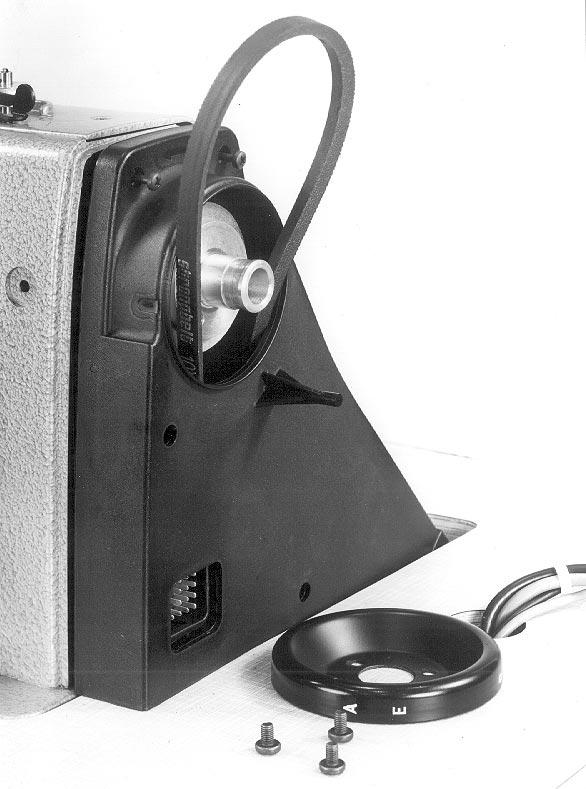
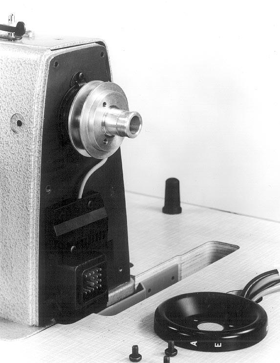
16 Establishing cable connections The electrical connections to the machine head are passed through the central plug-in connector 1. Introduce the plug into the bush of the sewing machine head. Pass the plug through the table top opening and introduce into the bush ST2 of the drive controller. 6.6 Installing the positioner Slip the positioner 3 onto the handwheel flange. The slot 6 on the positioner housing must catch over the anti-rotation element 5 on the belt guard. Tighten both threaded pins 2 on the position transmitter ring 4. Lead the connection cable 7 through the table top bore-hole and pass it down. Introduce the plug of the connection cable into the bush B1 of the drive controller. 16
17 6.7 Equipotential bonding 1 2 The grounding cable 1 (in the accessories) guides the static charges of the machine head via the sewing motor to the ground. Fasten the cable lug of the grounding cable by the screw (M4) and by the shim to the base of the sewing motor. Pass up the grounding cable. Fasten the grounding cable 1 by flat connector 2 to the machine base plate. 17
18 6.8 Checking the direction of rotation NOTE! It is absolutely necessary to check the direction of rotation of the sewing motor prior to putting the special sewing machine into operation. Damages can result if the special sewing machine is started to run in the wring direction of rotation. The arrow in the illustration shows the proper direction of rotation (counter clockwise rotation). The special sewing machines, that are supplied fully assembled, have been factory-set for the counter clockwise rotation (when looking at the belt pulley. If the special sewing machine is supplied by single components, check the direction of rotation. The direction of rotation is set on the control panel by means of the parameter F-161 (dre). For checking the direction of rotation: Introduce the mains plug. Turn on main switch. Call on the control panel the parameter F-161 of the technician level. The parameter must be set to the value " 1 " (counter clockwise rotation). If required, correct the parameter value. NOTE! Following a change of the direction of rotation, the positions must be programmed once again. 18
19 6.9 Checking the positioning Reference position The reference position is the starting point for all factory-set positions. In the reference position, the point of the lowered needle stands level with the top of the throat plate. Position 1 The 1st position serves for starting the cutting process if the sewing machine is supplied with a thread cutter. The sewing machine is then 2 mm behind its lower dead point. Position 2 In the 2ne position, the thread take-up lever must be in its upper position. Checking the positioning After thread cutting, the sewing machine must stop in the 2nd position (thread take up lever in upper position). Turn on main switch. Lower the pedal briefly forwards. Lower the pedal backwards completely and hold it lowered. The thread will be cut. The sewing machine will stop in the 2nd position (thread take-up lever in upper position). Check whether the thread take-up lever stands in its upper dead position. Normally, here ends the checking process. Should it be necessary to correct the factory setting, proceed for programming the positions as follows Setting the positions It is necessary to proceed to a new setting of the position transmitter after following operations: Fitting the position transmitter when installing the special sewing machine Removing the position transmitter Replacing the position transmitter Replacing the complete drive controller The digital position transmitter does not require any mechanical adjustments. It is only necessary to set the reference position when taking the machine into service for the first time. The machine positions are sensed by steps (increments) by the position transmitter and they are shown by the display. One rotation of the handwheel corresponds to 512 steps. The change of the display is done by 2 steps. A change from one display value to the other corresponds consequently to a rotation angle of about 1,4. The angle position of the positions 1 and 2 in respect top the reference position is defined by a certain number of increments. 19
20 Programming steps: 1. Calling up programming mode - Turn off main switch. - Operate the key "P" and hold it operated. - Turn on main switch. The display will show "C-0000". - Release the key "P". 2. Changing over to the technician level - Enter code number "1907" by the digital keys "1...0". - Operate the key "E". The controller will change over to the technician level ". The display will show the parameter no. "F-100". - If a wrong code number is entered, the display will show "C-0000 Info F1". Enter again. 3. Programming reference position - Enter parameter number "170" by the digital keys "1...0". - Operate the key "E". The display swill show the parameter "F-170" together with the code designation "Sr1" (Service routine 1). The LED above the key "F" will be blinking. - Operate the key "F". The display will show "Position 0". - Turn the handwheel until the reference position is attained (Needle point flush with the throat plate level). - Operate the key "P". The position set will be memorised. 4. Programming position 1 - Enter parameter no. "171" by the digital keys "1...0". - Operate the key "E". The display will show the parameter "F-171" together with the code designation "Sr2" (Service routine 2). The LED above the key "F" will be blinking. - Operate the key "F". The display will show "Position 1" and the respective number of increments. Pos1 = 151, Pos1a = Turn the handwheel until the 1st position is attained. 5. Programming 2nd position - Operate the key "E". The display will show "Position 2" and the respective number of increments. Pos2 = 460, Pos2a = Turn the handwheel until the 2nd position is attained. 20
21 6. Parameter setting Following parameters must be set before putting the machine into operation. (see also the parameter sheet PB05) F-111 n2 = 2500 upper limit of the maximum speed F-115 n6 = 250 Softstart speed F-119 nst = 2 Speed graduation slightly progressive F-190 ifa = 300 Engagement angle FA F-191 FSA = 100 Disengagement delay of the thread tension release F-202 br1 = 5 Braking effect 7. Leaving correction mode - Operate the key "P". 8. Memorizing the setting - Tread the pedal briefly forwards. - Tread the pedal completely backwards. The threads will be cut. The sewing feet will be lifted. The corrected setting will be memorised. - The sewing machine is ready to operate. NOTE! For terminating the correction process it is absolutely necessary to sew a short distance. This will finally memorise the modified setting. If no sewing is done, the setting will be lost after turning off the main switch. 21
22
23 7. Pneumatic connection NOTE! A perfect function of the pneumatic elements will only be ensured if the line pressure ranges between 8 and 10 bar. The service pressure of the special sewing machine amounts to 6 bar. Pneumatic connection package Under the ref. no you can order a pneumatic connection package for stands with compressed air conditioning unit. It includes following parts:: - Connection hose, 5 m long Ø = 9 mm - Hose nozzles and hose binders - Coupling socket and coupling plug Connecting compressed air conditioning unit Fasten the compressed air conditioning unit 1 to the stand strut by a square, by screws and by a shackle. Connect the compressed air conditioning unit to the compressed air line by the connecting hose 2 ( Ø = 9 mm) and by the hose coupling R1/4" Connecting the compressed air conditioning unit to the sewing machine head Connect the hose 4 (in the accessories) with the distribution plate on the machine head. Setting the service pressure Set the service pressure to 6 bar. It is shown by the pressure gauge 5 For setting the service pressure, pull up the rotary handle 3 and turn it. Increase the pressure = by turning the rotary handle 3 clockwise Reduce the pressure = By turning the rotary handle 3 counter clockwise 3 23
24 L = H E? J H % % & ' " # $ 2 -!
25 8. Oil lubrication Caution: Danger of bodily injuries! Oil can cause skin irritations. Avoid longer contacts with the skin. Wash the contaminated skin thoroughly. ACHTUNG! The handling and the disposal of the mineral oil is subjected to legal rules. Take the used oil to an authorised disposal centre. Protect the environment. Take care not to spill any oil. For replenishing the oil container use exclusively the oil quality ESSO SP-NK 10 or an equal oil grade with following specifications: Viscosity at 40 C : 10 mm 2 /s Flash point: 150 C ESSO SP-NK 10 can be obtained from sales centres of DÜRKOPP ADLER AG under following reference numbers: 2 litre container: litre container: Lubrication of the machine head Fill the container with oil up to the mark "max.". Hook lubrication Lubricate the points 2 and 3 by some drops of oil. Check whether the felt 4 under the hook drives is sufficiently lubricated. If necessary, lubricate the felt 4 at the open right and left corner when installing. The toothed wheels of the hook drive have oil felts, supplied with oil by the felt 4. The felt 4 must be in contact with the oil felts of the hook drive. Oiling wicks and felt parts When installing and after longs periods of standstill oil slightly the wicks and the felt parts of the sewing machine. 25
26 9. Sewing test Following the installation, proceed to a sewing test! Introduce the mains plug. Caution: danger of bodily injuries! Turn off main switch. Switch off the sewing machine before threading the needle and the hook. Thread the bobbin (see the Operating Instructions). Turn on main switch. Fill the bobbin at low speed. Thread the needle and the hook (see the Operating Instructions). Select the material to be sewn. Conduct the sewing test first at low speed and then at an increasingly higher speed. Check whether the seems are meeting the requirements. If the requirements are not met, modify thread tensions (see the Operating Instructions). If required, check and, if necessary, also correct the settings specified in the Service Instructions. 26
Spezialnähmaschine. Betriebsanleitung. Instruction manual
 669 Spezialnähmaschine Betriebsanleitung Instruction manual D GB Postfach 17 03 51, D-33703 Bielefeld Potsdamer Straße 190, D-33719 Bielefeld Telefon +49 (0) 521 / 9 25-00 Telefax +49 (0) 521 / 9 25 24
Part 1: class 69 operating instructions
 Contents Page: Preface and general safety instructions Part 1: class 69 operating instructions 1. Product description............................ 5 2. Designated use.............................. 5 3.
ENGINEER S MANUAL No.01
 1-NEEDLE, UNISON FEED, LOCKSTITCH MACHINE (AUTOMATIC LUBRICATION) LU-1510 1-NEEDLE, UNISON FEED, LOCKSTITCH MACHINE WITH AUTOMATIC THREAD TRIMMER (AUTOMATIC LUBRICATION) LU-1510-7 1-NEEDLE, UNISON FEED,
PREMIER SERIES BY P1255RBL-18 P2339RBL-18
 PREMIER SERIES BY P1255RBL-18 P2339RBL-18 P2339RBL-18 P1255RBL-18 P2339RBL- P1255RB- P2339RBL- 1. P2339RBL 18 Machine casting components Line Part Number Description Qt. Notes 1 300 1002 Machine
Part 3: Service manual, class
 Contents Page: Part : Service manual, class 7-75. General.................................................. Gauges................................................. 4. Description and adjustment of the
CNC Knopfannähautomat CNC Automat for Button Sewing
 531 CNC Knopfannähautomat CNC Automat for Button Sewing Bedienanleitung / Operating Instructions Aufstellanleitung / Installation Instructions Serviceanleitung / Service Instructions 1 3 Postfach 17 03
IMPORTANT SAFETY INSTRUCTIONS
 CONTENTS 1.SPECIFICATIONS... 1 2.INSTALLATION... 1 3.INSTALLATION OF THE SYNCHRONIZER... 2 4.ASSEMBLY OF HAND WHEEL... 2 5.INSTALLATION OF HAND WHEEL... 2 6.INSTALLING THE BELT COVER... 3 7.ADJUSTING THE
Please read this manual before using the machine. Please keep this manual within easy reach for quick reference.
 DA-927A DA-928A INSTRUCTION MANUAL Please read this manual before using the machine. Please keep this manual within easy reach for quick reference. TWIN NEEDLE / THREE NEEDLE FEED OFF THE ARM DOUBLE CHAIN
DA-9270 TWIN NEEDLE (THREE NEEDLE) FEED OFF THE ARM DOUBLE CHAIN STITCHER. English
 FEED OFF THE ARM DOUBLE CHAIN STITCHER. English") TWIN NEEDLE (THREE NEEDLE) FEED OFF THE ARM DOUBLE CHAIN STITCHER English Thank you very much for buying a BROTHER sewing machine. Before using your new machine, please read the safety instructions below
TWIN NEEDLE (THREE NEEDLE) FEED OFF THE ARM DOUBLE CHAIN STITCHER English Thank you very much for buying a BROTHER sewing machine. Before using your new machine, please read the safety instructions below
Speedpocket. Sewing unit for runstitching of rectangular piped pockets. Operating Instructions. Installation Instructions. Service Instructions
 745-34 Speedpocket Sewing unit for runstitching of rectangular piped pockets Operating Instructions Installation Instructions Service Instructions Instructions for programming DAC 1 3 4 Postfach 17 03
Please read this manual before using the machine. Please keep this manual within easy reach for quick reference.
 INSTRUCTION MANUAL Please read this manual before using the machine. Please keep this manual within easy reach for quick reference. HIGH SPEED SINGLE NEEDLE STRAIGHT LOCK STITCHER Thank you very much for
M-TYPE CLASSIC M-TYPE PREMIUM. Additional Instructions. Electropneumatic needle cooling
 M-TYPE CLASSIC M-TYPE PREMIUM Additional Instructions Electropneumatic needle cooling IMPORTANT READ CAREFULLY BEFORE USE KEEP FOR FUTURE REFERENCE All rights reserved. Property of Dürkopp Adler AG and
Please read this manual before using the machine. Please keep this manual within easy reach for quick reference.
 INSTRUCTION MANUAL Please read this manual before using the machine. Please keep this manual within easy reach for quick reference. SINGLE NEEDLE DIRECT DRIVE STRAIGHT LOCK STITCHER WITH THREAD TRIMMER
MNEFDD54 & MNBCDD54 GALVANIZED WALL FANS Installation, Operation, and Maintenance Instructions
 FARM PRODUCTS DIVISION MEMBER OF AMCA AMERICAN COOLAIR CORPORATION P.O. BOX 2300 JACKSONVILLE, FLORIDA 32203 PHONE (904) 389-3646 FAX (904) 387-3449 E-MAIL - fans@coolair.com MNEFDD54 & MNBCDD54 GALVANIZED
Industrial Sewing Machine TECHNICAL MANUAL SEWING MACHINE HEAD. Electronic Pattern Sewing Machine. Model PLK-G1010 A180E593P03
 Industrial Sewing Machine TECHNICAL MANUAL SEWING MACHINE HEAD Electronic Pattern Sewing Machine Model PLK-G1010 A180E593P03 FOR SAFE USE Before the installation, operation, and inspection for this product,
CONTENTS 1. SPECIFICATIONS SET-UP FOR THE OPERATOR MAINTENANCE... 34
 ENGLISH ii CONTENTS. SPECIFICATIONS... 2. SET-UP.... Installing the motor unit... 2. Installing the control box... 3. Installing the belt... 2 4. Adjusting the pulley cover... 2 5. Installation and adjustment
Industrial Sewing Machine TECHNICAL MANUAL SEWING MACHINE HEAD. Electronic Pattern Sewing Machine. Model PLK-G2516 A180E621P01
 Industrial Sewing Machine TECHNICAL MANUAL SEWING MACHINE HEAD Electronic Pattern Sewing Machine Model PLK-G2516 A180E621P01 FOR SAFE USE Before the installation, operation, and inspection for this product,
Technical Data. Name: ERIKA Automat fully automatic machine to divide and to round dough pieces of the same size
 AUTOMAT MANUAL 1 Technical Data Name: ERIKA Automat fully automatic machine to divide and to round dough pieces of the same size Type Divisions Dough Portions (in ounces) Plate Nos. 3 30 1.0 3.5 #35 4/40A
PLC-1700 Series PLC-1710, , 1760, , 1760L
 Post-bed, Unison-feed, Lockstitch Machine PLC-1700 Series PLC-1710, 1710-7, 1760, 1760-7, 1760L ENGINEER S MANUAL 40040656 No.E372-00 Introduction This Engineer s Manual is for technical service engineers.
SC-922 InStruCtIon Manual
 SC-922 Instruction Manual CONTENTS I. SPECIFICATIONS... 1 II. SET-UP... 1 1. Installing to the table...1 2. Installing the motor unit...2 3. Installing the control box...2 4. Installing the belt...3 5.
MB-1800 Series INSTRUCTION MANUAL
 MB-800 Series INSTRUCTION MANUAL CONTENTS!. SPECIFICATIONS... @. NAME OF EACH COMPONENT.... Name of the main unit... #. INSTALLATION... $. PREPARATION OF THE SEWING MACHINE...7. Attaching the needle...
Industrial Sewing Machine TECHICAL MANUAL SEWING MACHINE HEAD. Electronic Pattern Sewing Machine. Model PLK-G1010 A180E593P02
 Industrial Sewing Machine TECHICAL MANUAL SEWING MACHINE HEAD Electronic Pattern Sewing Machine Model PLK-G1010 A180E593P02 FOR SAFE USE Before the installation, operation, and inspection for this product,
MSK-8900M Industrial Sewing Machine. Instruction Manual
 MSK-8900M Industrial Sewing Machine Instruction Manual CONTENTS Operation instruction. Brief introduction. Main specifications. Main parts name 4. The method of installation 5 5. Pareparation before sewing
MITSUBISHI. Industrial Sewing Machine. Model PLK-E1010 TECHNICAL MANUAL MECHANICAL VERSION. Electronic Pattern Sewing Machine A180E494P01
 MITSUBISHI Industrial Sewing Machine TECHNICAL MANUAL MECHANICAL VERSION Electronic Pattern Sewing Machine Model PLK-E00 A80E9P0 FOR YOUR SAFETY! If you operate the sewing machine first time, please make
Parts and Service Manual
 Section II Parts and Service Manual (70241A) CLARKE TECHNOLOGY Operator's Manual - MINI MAX Page -29- Frame and Front Cover Assembly Drawing 2/01 Page -30- CLARKE TECHNOLOGY Operator's Manual -MINI MAX
USER S MANUAL. SS-7350 Series. Small cylinder bed interlock sewing machine
 R USERS MANUAL SS-7350 Series Small cylinder bed interlock sewing machine R Best Quality Best Price Best Service 1. Thank you for purchasing our product. Based on the rich expertise and experience accumulated
ORIGINAL SPARE PARTS CHD-6330
 ORIGINAL SPARE PARTS CHD-6330 85010075/02 Revision 02/2013 FRAME 1.0 FRAME 1.0 Rif Code Description 1 *4399880 SCREW TE 10x40 2 *4399378 WASHER D.10 (10,5x21x2) 3 *6611330 SUPPORT 4 *7910913 CHUCK 5 *4399288
Please read this manual before using the machine. Please keep this manual within easy reach for quick reference.
 INSTRUCTION MANUAL Please read this manual before using the machine. Please keep this manual within easy reach for quick reference. SINGLE NEEDLE DIRECT DRIVE LOCK STITCHER WITH ELECTRONIC FEEDING SYSTEM
Spezialnähmaschine. Bedienanleitung. Operating Instructions. Instructions de maniement
 367 Spezialnähmaschine Bedienanleitung Operating Instructions Instructions de maniement D GB F Postfach 17 03 51, D-33703 Bielefeld Potsdamer Straße 190, D-33719 Bielefeld Telefon +49 (0) 5 21/ 9 25-00
Hakki Pilke Raven spare parts manual
 1 ENGLISH Hakki Pilke Raven spare parts manual Valimotie 1, FI-85800 Haapajärvi, FINLAND Tel. +358 8 772 7300, Fax +358 8 772 732 info@maaselankone.fi, www.maaselankone.fi 2 Table of contents 1 Upper section
Please read this manual before using the machine. Please keep this manual within easy reach for quick reference.
 INSTRUCTION MANUAL Please read this manual before using the machine. Please keep this manual within easy reach for quick reference. SINGLE NEEDLE DIRECT DRIVE LOCK STITCHER WITH ELECTRONIC FEEDING SYSTEM
Industrial Sewing Machine TECHNICAL MANUAL MECHANICAL VERSION. Electronic Pattern Sewing Machine. Model PLK-E2010R A180E530P01
 Industrial Sewing Machine TECHNICAL MANUAL MECHANICAL VERSION Electronic Pattern Sewing Machine Model PLK-E2010R A180E530P01 FOR YOUR SAFETY! If you are operating the sewing machine for first time, please
BAS-300G-484 BAS-300G-484 SF
 BAS-300G-484 BAS-300G-484 SF DIRECT DRIVE PROGRAMMABLE ELECTRONIC PATTERN SEWER Please read this manual before using the machine. Please keep this manual within easy reach for quick reference.
Spezialnähmaschine. Betriebsanleitung. Instruction manual
 669 Spezialnähmaschine Betriebsanleitung Instruction manual D GB Postfach 17 03 51, D-33703 Bielefeld Potsdamer Straße 190, D-33719 Bielefeld Telefon +49 (0) 521 / 9 25-00 Telefax +49 (0) 521 / 9 25 24
Installation Instructions
 GE Consumer & Industrial Appliances Installation Instructions Junction Box Cover Within this user bag, you will find a junction box cover and a #10 hex head screw used to attach the junction box cover
SuperKlean Washdown Products
 DURAREEL DR8 & DR8S INSTALLATION AND MAINTENANCE INSTRUCTIONS **DO NOT THROW AWAY AFTER INSTALLATION** **SAVE AND DISPLAY PROMINENTLY WHERE THIS EQUIPMENT IS USED** GENERAL WARNINGS High pressure and hot
Special Sewing Machine
 884 Special Sewing Machine Instruction manual Postfach 17 03 51, D-33703 Bielefeld Potsdamer Straße 190, D-33719 Bielefeld Telefon +49 (0) 521 / 9 25-00 Telefax +49 (0) 521 / 9 25 24 35 www.duerkopp-adler.com
RH-981A ENGLISH ELECTRONIC EYELET BUTTON HOLER
 ENGLISH ELECTRONIC EYELET BUTTON HOLER Thank you very much for buying a BROTHER sewing machine. Before using your new machine, please read the safety instructions below and the explanations given in the
Built-In Dishwasher. Installation Instructions. BEFORE YOU BEGIN Read these instructions completely and carefully. IMPORTANT The dishwasher MUST be
 Installation Instructions Built-In Dishwasher If you have questions, call 800.GE.CARES (800.432.2737) or visit our website at: www.ge.com BEFORE YOU BEGIN Read these instructions completely and carefully.
AK-154 INSTRUCTION MANUAL
 AK-154 INSTRUCTION MANUAL 1 CONTENTS 1. FEATURES... 1 2. INSTALLATION... 2 3. HOW TO SELECT THE FUNCTION OF AUTO-LIFTER... 5 4. OTHERS (Advanced edition)... 6 4-1. Function for reducing the presser foot
Instruction Manual and Parts List. Ultra High Speed Overedge and Safety Stitch Machine
 Instruction Manual and Parts List Ultra High Speed Overedge and Safety Stitch Machine 32D 3M-04 3M-04 / KS 32M-05 34M-04 24M-24 24M-24 / KS 244M-24 25M-35 25M-35 / KH 25M-55 25M-55 / KH 25M-56 25H-56 /
MODEL: PE770 Published: Jul.,2009 Revised: Feb.,2013
 MODEL: PE770 Published: Jul.,2009 Revised: Feb.,2013 MODEL LIST Model Countries (Added Date) PE770 USA, ARG, PRY, BRA120V, BRA220V (Feb / 2011) PE770 AUS&NZL (Jul / 2012) Country Code & Abbreviation of
USER S MANUAL. KM-1060BL Series KM-1060BL KM-1060BL-7 KM-1062BL KM-1062BL-7
 USER S MANUAL KM-1060BL Series KM-1060BL KM-1060BL-7 KM-1062BL KM-1062BL-7 R Best Quality Best Price Best Service 1. Thank you for purchasing our product. Based on the rich expertise and experience accumulated
PARTS LIST. CoverPro 900CP & 1000CP
 PARTS LIST CoverPro 900CP & 00CP 1 5 2 7 9 3 6 11 20 23 12 13 1 19 21 2 26 17 16 1 22 15 25 1 No. Part number Description 1 79560300 Face cover unit 2 79501600 Face cover 3 0602006 Thread cutter unit 000115700
PLC-2700 Series INSTRUCTION MANUAL
 PLC-2700 Series INSTRUCTION MNUL CONTENTS 1. SPECIFICTIONS... 1 2. INSTLLTION... 4 2-1. Installation of the sewing machine...4 2-2. djusting the belt tension (PLC-2710, 2760, 2760L, 2765)...6 2-3. Pneumatic
ORIGINAL SPARE PARTS CHD-6330
 ORIGINAL SPARE PARTS CHD-6330 85010075/00 Revision 07/2008 FRAME 1.0 FRAME 1.0 Rif Code Description 1 *4399880 SCREW TE 10x40 2 *4399378 WASHER D.10 (10,5x21x2) 3 *6611330 SUPPORT 4 *7910913 CHUCK 5 *4399288
KE-430HX KE-430HS BE-438HX
 KE-430HX KE-430HS BE-438HX INSTRUCTION MANUAL Please read this manual before using the machine. Please keep this manual within easy reach for quick reference. ELECTRONIC DIRECT DRIVE LOCKSTITCH BAR TACKER
INLET DAMPER WALL FAN UNIT
 FARM PRODUCTS DIVISION MEMBER OF AMCA AMERICAN COOLAIR CORPORATION P.O. BOX 2300 JACKSONVILLE, FLORIDA 32203 PHONE (904) 389-3646 FAX (904) 387-3449 E-MAIL - agfans@coolair.com INLET DAMPER WALL FAN UNIT
Model PLK-G5050 PLK-G10050
 Industrial Sewing Machine TECHNICAL MANUAL SEWING MACHINE HEAD Electronic Pattern Sewing Machine Model PLK-G5050 PLK-G10050 A180E686P01 FOR SAFE USE Before the installation, operation, and inspection for
PARTS LIST. Specification code: (JAI 45231) (JA) (JCA) (JUK) (JHBV)
 (JA) (JCA) (JUK) (JHBV)") PARTS LIST Specification code: 832-711-004 (JAI 45231) 832-712-005 (JA) 832-713-006 (JCA) 832-714-007 (JUK) 832-716-009 (JHBV) 14 13 1 2 6 10 12 9 11 8 7 3 5 4 7 1 KEY PART NO. NO. NAME 1 832649011 Needle
PARTS LIST Specification code: 832-711-004 (JAI 45231) 832-712-005 (JA) 832-713-006 (JCA) 832-714-007 (JUK) 832-716-009 (JHBV) 14 13 1 2 6 10 12 9 11 8 7 3 5 4 7 1 KEY PART NO. NO. NAME 1 832649011 Needle
Exploded View - Model J-7020M/J-7040M Miter Cut-off Saw Base
 22 Exploded View - Model J-7020M/J-7040M Miter Cut-off Saw Base Parts List - Model J-7020M/J-7040M Miter Cut-off Saw Base 1 J-5507591 Base, Machine 1 1-1 5512197 Plug, Drain (3/8in, PT) 2 5507592 Screw,
Liste de pièces Lista de Piezas Parts List
 H74 Liste de pièces Lista de Piezas Parts List 104 23 73-96 17 Nov 2011 A 2 Singer H74 Pos Part No Description 1 416484501 THREAD TAKE UP LEVER COMPLETE 2 416147701 THREAD TAKE UP LEVER SUPPORTER 3 416116001
Spezialnähmaschine. Betriebsanleitung. Instruction manual
 838 Spezialnähmaschine Betriebsanleitung Instruction manual DE EN Postfach 7 03 5, D-33703 Bielefeld Potsdamer Straße 90, D-3379 Bielefeld Telefon +49 (0) 52 / 9 25-00 Telefax +49 (0) 52 / 9 25 24 35 www.duerkopp-adler.com
SIMPLICITY MODEL LVPB7200
 SIMPLICITY MODEL 7200 LVPB7200 BODY GROUP 7200 BODY GROUP 7200 Key Part No Description Key Part No Description 1 7.8-PLAIN Simplicity 7000 Paper Bag 29 D625-0231 Suction Inlet Complete 2 B221-0213 Dust
Installation Instructions
 Installation Instructions Built-In Dishwasher If you have questions, call 800-GECARES or visit our website at: www.geappliances.com BEFORE YOU BEGIN Read these instructions completely and carefully. IMPORTANT
INSTALLATION AND MAINTENANCE OF THE "THOMPSON-BRITISH" AUTOMATIC PLATEN
 INSTALLATION AND MAINTENANCE OF THE "THOMPSON-BRITISH" AUTOMATIC PLATEN Installation and Maintenance of The "Thompson-British" Auto Platen Lifting Bolt. Motor. Direction of rotation. Oiling. The machine
568X, 587X, 588X Series
 Please read and save this Repair Parts Manual. Read this manual and the General Operating Instructions carefully before attempting to assemble, install, operate or maintain the product described. Protect
Spezialnähmaschine. Betriebsanleitung. Instruction manual
 887 Spezialnähmaschine Betriebsanleitung Instruction manual Postfach 17 03 51, D-33703 Bielefeld Potsdamer Straße 190, D-33719 Bielefeld Telefon +49 (0) 521 / 9 25-00 Telefax +49 (0) 521 / 9 25 24 35 www.duerkopp-adler.com
Cable Drum Machine. Operation Manual 40 SERIES. Cleans 2" to 4" lines up to 75' N O T F O R R O O T S
 Cable Drum Machine Operation Manual 40 SERIES Cleans 2" to 4" lines up to 75' Used For: Sinks, Showers & Floor Drains N O T F O R R O O T S WARNING - Read All Instructions, When Using Electric Tools, Basic
Nilfisk Inc Winnetka Avenue North Minneapolis, MN REV.03( ) VF80189
 VF80189") Nilfisk Inc. 9435 Winnetka Avenue North Minneapolis, MN 55445 www.usviper.com REV.03(05-) VF8089 SAFETY PRECAUTIONS This machine is intended for commercial use. It is constructed for use in an indoor
Nilfisk Inc. 9435 Winnetka Avenue North Minneapolis, MN 55445 www.usviper.com REV.03(05-) VF8089 SAFETY PRECAUTIONS This machine is intended for commercial use. It is constructed for use in an indoor
Please read this manual before using the machine. Please keep this manual within easy reach for quick reference.
 INSTRUCTION MANUAL Please read this manual before using the machine. Please keep this manual within easy reach for quick reference. ELECTRONIC DIRECT DRIVE LOCKSTITCH BUTTON HOLER Thank you very much for
INSTALLATION, OPERATION, AND MAINTENANCE MANUAL
 INSTALLATION, OPERATION, AND MAINTENANCE MANUAL TUBE AXIAL FANS BTA, WTA, HTA, DDA The purpose of this manual is to aid in the proper installation and operation of the fans. These instructions are intended
LK-1903B/BR35 INSTRUCTION MANUAL
 LK-1903B/BR35 INSTRUCTION MANUAL CONTENTS I. SPECIFICATIONS...1 1. Specifications... 1 2. Model classification according to the button size... 2 3. Shape of buttons... 2 II. NAME OF EACH COMPONENT...3
USER S MANUAL. SPS/E-1507 Series. Electronically Controlled Pattern Sewing Machine (Mechanical Part)
") R USERS MANUAL SPS/E-1507 Series Electronically Controlled Pattern Sewing Machine (Mechanical Part) R Best Quality Best Price Best Service 1. Thank you for purchasing our product. Based on the rich expertise
R USERS MANUAL SPS/E-1507 Series Electronically Controlled Pattern Sewing Machine (Mechanical Part) R Best Quality Best Price Best Service 1. Thank you for purchasing our product. Based on the rich expertise
User s Manual: WERI Mini Applicator
 User s Manual: User s Manual Page 1 of 15 Table of Content 1 Document revision history... 2 2 Important warnings... 3 3 Symbols... 4 4 Identification... 5 5 Technical data... 5 6 Installation (trained
Refrigerator BRFB1920SS BRFB1900FBI BRFB1920FBI
 Refrigerator BRFB1920SS BRFB1900FBI BRFB1920FBI Table of Contents Symbols and Their Meanings... 3 Product weight... 5 Load bearing capacity of the doors... 5 Climate class... 5 Product Information:...
DDL-900A INSTRUCTION MANUAL
 DDL-900A INSTRUCTION MANUAL COVERI CONTENTS I. SPECIFICATIONS... 1 II. SET-UP... 3 1. Installation...3 2. Installing the pedal sensor...4 3. Installing the power switch (for CE)...4 4. Connecting the connector...5
KE-430D BE-438D ELECTRONIC DIRECT DRIVE LOCKSTITCH BAR TACKER ELECTRONIC DIRECT DRIVE LOCKSTITCH BUTTON SEWER
 KE-430D ELECTRONIC DIRECT DRIVE LOCKSTITCH BAR TACKER BE-438D ELECTRONIC DIRECT DRIVE LOCKSTITCH BUTTON SEWER Thank you very much for buying a BROTHER sewing machine. Before using your new machine, please
Spezialnähmaschine. Betriebsanleitung. Instruction manual
 869 Spezialnähmaschine Betriebsanleitung Instruction manual D GB Postfach 17 03 51, D-33703 Bielefeld Potsdamer Straße 190, D-33719 Bielefeld Telefon +49 (0) 521 / 9 25-00 Telefax +49 (0) 521 / 9 25 24
60" Tulle PatioTM. Instruction Manual. A Kichler Select ceiling fan
 60" Tulle PatioTM A Kichler Select ceiling fan cul Certified for Wet Location Kichler Lighting 7711 East Pleasant Valley Road P.O. Box 318010 Cleveland, Ohio 44131-8010 Customer Service 866.558.5706 8:30
42 Kevlar. Instruction Manual. Kichler Lighting 7711 East Pleasant Valley Road P.O. Box Cleveland, Ohio
 42 Kevlar Kichler Lighting 7711 East Pleasant Valley Road P.O. Box 318010 Cleveland, Ohio 44131-8010 Customer Service 866.558.5706 8:30 AM to 5:00 PM EST, Monday - Friday Instruction Manual 1 1. SAFETY
RICCAR VIBRANCE VIBC.2
 RICCAR VIBRANCE VIBC.2 LRPB-VIBC.2 BODY GROUP BODY GROUP Key Part No Description Key Part No Description 1 D224-0630 Dust Cover Assembly 25 B210-0605 Rear Wheel Axle 2 A732-5300 Combination Washer and
DDL-900BB INSTRUCTION MANUAL
 DDL-900BB INSTRUCTION MANUAL CONTENTS I. SPECIFICATIONS... 1 II. SET-UP... 3 1. Installation...3 2. Installing the pedal sensor...4 3. Installing the power switch (for CE)...5 4. Connecting the connector...6
DAGNY LK. Ceiling Mounted Rotational Fan READ AND SAVE THESE INSTRUCTIONS. FAN RATING AC 110V~60Hz
 DAGNY LK Ceiling Mounted Rotational Fan READ AND SAVE THESE INSTRUCTIONS FAN RATING AC 110V~60Hz Please do not use any electric or battery powered tools in the assembly and installation of this or any
TS-49 PART # DPEC DATE: REVISED:
 36-6022 COMPACT PORTABLE TABLE SAW - w/mobile STAND 38 73 325 176 x2 x4 x2 324 326 323 x2 P1 36-6022 COMPACT PORTABLE TABLE SAW - w/mobile STAND 116 191 P2 36-6022 COMPACT PORTABLE TABLE SAW - w/mobile
LK3 B434E LK3-B434EX LK3 B434EX/SF Electronic Lockstitch Pattern Tacker Electronic Lockstitch Pattern Tacker with Stepping Foot
 LK3 B434E LK3-B434EX LK3 B434EX/SF Electronic Lockstitch Pattern Tacker Electronic Lockstitch Pattern Tacker with Stepping Foot Specifications Model LK3 B434E LK3 B434EX LK3 B434EX / SF Application Thin,
Altra Series Dampener
 Crestline TM Altra Series Dampener Installation Instructions Heidelberg MO X88-66 10/97 Rev-A GENERAL INFORMATION ATTENTION CRESTLINE ALTRA SERIES TM DAMPENER OWNER! Accel Graphic Systems provides parts
Cleaning unit for coolant. :_decftez`_>r_fr] Book No.: V2
![Cleaning unit for coolant. :_decftez`_>r_fr] Book No.: V2](/thumbs/90/104143238.jpg "Cleaning unit for coolant. :_decftez`_>r_fr] Book No.: V2") Cleaning unit for coolant :_decftez`_>r_fr] Book No.: 1271526-02 V2 Alfa Laval Separation AB Separator Manuals, dept. SKEL S-147 80 Tumba, Sweden Telephone: +46 8 53 06 50 00 Telefax: +46 8 53 03 10 40
Cleaning unit for coolant :_decftez`_>r_fr] Book No.: 1271526-02 V2 Alfa Laval Separation AB Separator Manuals, dept. SKEL S-147 80 Tumba, Sweden Telephone: +46 8 53 06 50 00 Telefax: +46 8 53 03 10 40
TK-1801, TK-1811 TK-1801, TKR-1811
 TK-1801, TK-1811 TK-1801, TKR-1811 Pneumatic Zero Energy Band Room Thermostats General Instructions APPLICATION For proportional control of pneumatically-operated sequenced heating and cooling valves and/or
REMOVE AND INSTALL AIR CLEANER ASSEMBLY
 REMOVE AND INSTALL AIR CLEANER ASSEM 50 DISASSEM AND ASSEM- REMOVE AND INSTALL AIR CLEANER ASSEM Cover Connector Air cleaner assembly Place the machine on a level ground, lower the work equipment to the
50 Disassembly and assembly Cab and its attachments
 When adjustment is needed after performing check in step 8; 3) Close front window assembly (1). 4) Loosen locknuts (26) of right and left rubber stoppers (24) and move the stoppers backward so that front
888 Operating Instructions
 888 Operating Instructions All rights reserved. Property of Dürkopp Adler AG and copyrighted. Reproduction or publication of the content in any manner, even in extracts, without prior written permission
DDL-8700B-7 INSTRUCTION MANUAL
 DDL-8700B-7 INSTRUCTION MANUAL I CONTENTS I. SPECIFICATIONS... 1 II. SET-UP... 3 1. Installation...3 2. Installing the pedal sensor...4 3. Connecting the connector...4 4. How to install the power plug...5
OWNERS MANUAL FOR MEC 300E ATA
 OWNERS MANUAL FOR MEC 300E ATA PLEASE READ AND FULLY UNDERSTAND THE INSTRUCTIONS PRIOR TO SETTING OR TUNING THE MACHINE. CAUTION: ANY MEC CLAY TARGET MACHINE MUST BE IN THE DISARMED STATE WITH THE BATTERY
Gen II Entree Bath. Maintenance Manual. All Models. Important Safety Instructions Read & Follow All Instructions Thoroughly
 Gen II Entree Bath All Models Maintenance Manual Important Safety Instructions Read & Follow All Instructions Thoroughly Note: The serial tag is at the first page of this manual package. The Standards
Maintenance 5-1. Good maintenance is essential for cleaning results, and long economical life of the washer.
 Maintenance 5-1 5 Maintenance Purpose This chapter discusses the maintenance of your StingRay Parts Washer. In general, the washer is not maintenance-intensive. A few key items, however, need regular,
Installation and Operating Instructions
 ELECTRICALLY OPERATED FOLDING STAIRS Installation and Operating Instructions Premier Loft Ladders ltd Registered Office: 2 Dawson Drive, Trimley St Mary, Felixstowe, Suffolk. IP11 0YW Registered in England
/11, -14/31 INSTRUCTION MANUAL. This instruction manual applies to machines from the following serial numbers onwards: #
 3834-4/, -4/3 INSTRUCTION MANUAL This instruction manual applies to machines from the following serial numbers onwards: # 2 733 53 296-2-8 936/002 Betriebsanleitung engl. 06.09 This Instruction manual
PARTS BOOK GT-541 GARMENT PRINTER. The latest parts information, refer to the Parts Navigation.
 GT-541 PARTS BOOK GARMENT PRINTER The latest parts information, refer to the Parts Navigation. http://partsbook.brother.co.jp/partsnavi_em/eng/ Notes for using this parts book 1. This book was prepared
AMS-224EN4530R / AW-3 AMS-224EN6030R / AW-3 INSTRUCTION MANUAL
 AMS-224EN4530R / AW-3 AMS-224EN6030R / AW-3 INSTRUCTION MANUAL 1 CONTENTS 1. GENERAL...1 1-1. Specifications of AW-3...1 1-2. Configuration...2 2. INSTALLATION...4 2-1. Installation procedure...4 2-2.
Select. Sutter PlaceTM. Instruction Manual. A Kichler Select ceiling fan
 Sutter PlaceTM A Kichler ceiling fan Kichler Lighting 7711 East Pleasant Valley Road P.O. Box 318010 Cleveland, Ohio 44131-8010 Customer Service 866.558.5706 8:30 AM to 5:00 PM EST, Monday - Friday Instruction
BARRACUDA 200ZW PORTABLE WALKING FOOT SEWING MACHINE INSTRUCTION MANUAL
 BARRACUDA 00ZW PORTABLE WALKING FOOT SEWING MACHINE INSTRUCTION MANUAL THE BARRACUDA 00ZW PORTABLE WALKING FOOT SEWING MACHINE INSTRUCTION MANUAL MATERIAL IS OWNED BY RELIABLE AND MAY NOT BE REPRODUCED
Fig. 1. Bottle Height---Top of bottle MUST be at this height or slightly higher.
 P12 Corker Addendum: Setup and Maintenance Read this addendum and the MEP manual carefully before operating the corker. One person should be assigned to maintain the corker. Only this primary operator
Chapter 3 Cooling, heating and ventilation systems
 3 1 Chapter 3 Cooling, heating and ventilation systems Contents Antifreeze mixture..............................see Chapter 1 Cooling fan assembly - testing, removal and refitting.............8 Cooling
Installation Instructions
 Installation Instructions For Fully Integrated NoFrost Combined Refrigerator-Freezers HC 2062 HCB 2062 HC/HCB 20 7082 373-00 Important PLEASE READ AND FOLLOW THESE INSTRUCTIONS These instructions contain
Bead Roller Operating, Servicing, and Safety Instruction Manual
 Bead Roller Operating, Servicing, and Safety Instruction Manual CAUTION: Read and Understand These Operating, Servicing, and Safety Instructions, Before Using This Machine. 1-800-67-26 10 Cooperative Way
INSTRUCTION MANUAL. This instruction manual applies to machines from the following serial numbers onwards: #
 245 246 INSTRUCTION MANUAL This instruction manual applies to machines from the following serial numbers onwards: # 6 500 24 296-2-9 99/002 Betriebsanleitung engl. 05.2 This Instruction Manual is valid
OPERATING MANUAL Gfp 255C Please read this manual carefully before operating!
 OPERATING MANUAL Gfp 255C Please read this manual carefully before operating! Unpacking, assembly, and operating videos are available at www.gfpsmoothstart.com 1 Table of Contents Gfp 255C March 2015 Contents
Spezialnähmaschine. Betriebsanleitung. Instruction manual
 171 173 Spezialnähmaschine Betriebsanleitung Instruction manual D GB Postfach 17 03 51, D-33703 Bielefeld Potsdamer Straße 190, D-33719 Bielefeld Telefon +49 (0) 521 / 9 25-00 Telefax +49 (0) 521 / 9 25
OPERATING MANUAL Gfp 800 Series
 OPERATING MANUAL Gfp 800 Series Please read this manual carefully before operating! 1 Contents Table of Contents Page 1. Introduction 3 2. Important Safety Instructions.. 3 3. Installation Safeguards..