Installation Instructions
|
|
|
- Barnaby Turner
- 5 years ago
- Views:
Transcription

1 PAGE 1 Installation Instructions Important information about your new a/c system. Please read the following directions prior to installing this a/c system. PN: CK6772-1CHPU Chevy PU A/C Kit Contact us by or phone if you need any assistance or information regarding this a/c system SALES@NACKITS.COM
2 Important information about your system, and warranty DO NOT ADD ANY OIL TO ANY PART OF THE SYSTEM. DO NOT USE THE SIGHT GLASS TO CHARGE THE SYSTEM. DO NOT OVERCHARGE THE SYSTEM. Th Kit is designed to work with R134a refrigerant, not any other refrigerant (freon). The system has been designed and tested using R134a refrigerant. The systems performance with this freon was as expected. Vent temperature of F Degrees, and a high side pressure reading at psi. The system should not exceed 250psi on the high side, and the low side will stabilize if all is installed correctly. WE NEED THE HIGH SIDE GAUGE READING IN ORDER TO HELP WITH ANY PROBLEMS. The system needs to be evacuated for maximum performance. The system will take 1.50 lbs of R134a refrigerant, or two cans. You want the high side to be psi when the system is on and the is idle. DO NOT ADD DYE TO CHECK THE SYSTEM. WE HAVE HAD PROBLEMS WITH THE EXPANSION VALVES GETTING CLOGGED. If you have a problem with the system we ask to call before diagnosing or changing any parts. We can fix problems easier if the system is not tampered with. If you have a warranty claim you need to call prior to shipping any parts back. OUR POLICY IS TO GET THE OLD PART BACK PRIOR TO SHIPPING ANY NEW PARTS OUT. We are not responsible for the following: Clogged expansion valve from too much oil, or dye Cracked compressors from improper installation Compressor with broken valves from overcharging of oil or refrigerant Burned up clutches from to high of head pressure We will be here to serve you seven days a week by phone and / or Please contact us if you need assistance
3 PAGE 2 The Nostalgic AC Parts team would like to thank you for your recent purchase of a complete a/c kit for your car or truck. There are a few steps that must be followed in order for your a/c system to operate properly. The HIGH SIDE gauge reading should not exceed 220 PSI. We MUST have the HIGH SIDE gauge reading if you need any assistance in correcting a potential problem. If you purchased the a/c compressor from NAC, DO NOT ADD ANY OIL, DYE, LEAK SEALANTS OR OTHER ADDITIVES TO ANY PART OF THE SYSTEM. If oil is required NAC will provide an additional sheet with directions on filling the system with oil. Be sure you have the correct pulleys for the engine prior to installing the kit. Pulleys are not included unless specified when the kit is ordered. Insulation is very important. Be sure to insulate the firewall and floorboard prior to installing the evaporator unit. It is very important to insulate the floor and firewall behind the evaporator unit. There should be adequate airflow from the radiator fan, and a sufficient amount of room between the condenser and radiator. Make sure the CONDENSER HAS A TUNNEL EFFECT OF AIRFLOW THAT FLOWS THROUGH THE CONDENSER AND RADIATOR. Foam can be put in between condenser and the radiator edges to achieve a proper airflow effect. There should be ¼ to 1 gap in between the radiator and condenser. EFFECTS OF INADEQUATE AIRFLOW: the compressor may act like it is locking up, warm air only from the vents, overheating of the engine, high head pressure, air blows cold at idle and blows warm while driving, and more. Find the proper flow of the water prior to installing the heater control valve. Water should be turned off prior to entering the evaporator / heating unit. It should only be turned off when the heat is needed. If you are experiencing warm air out of the evaporator check the compressor low side fitting. If it is ice cold then the heater valve is not hooked up properly. DO NOT USE THE SIGHT GLASS! The system should be charged with R- 134a ONLY. If you do not follow this instruction your warranty may be void and you may not be eligible for technical assistance. EFFECTS OF OVERCHARGING: Compressor is noisy, engine overheating, warm air only from the vents, and more. If a problem exists after checking all these conditions you may call or for technical assistance. IF YOU DO NOT HAVE THE HIGH SIDE GAUGE READING WE WILL NOT BE ABLE TO ASSIST YOU IN FIXING THE PROBLEM.
4 PAGE 3 PARTS CHECKLIST Compressor with Oil PN: Evaporator Unit PN: UD-140 Drier PN: High Low Pressure switch PN: Binary Pig Tail PN: Condenser PN: Engine Mount kit (Engine specific) Hardware bag kit PN: Includes: Four grommets 12 self tapping screws #6,8,10 O-rings Cork tape Evap. Mount Brackets Drain Tube Nuts / Bolts / Washers Hose Kit R-134a Sticker Directions PN:HK-920 PN: SZ100


5 PAGE 4 Installing the Evaporator unit: STEP ONE 1) The evaporator is going to mount under the dashboard from the passenger side to the right of the steering column. The unit will hit the factory heater box so it will have to be trimmed. You do not have remove the box to trim it. ) After the hole is cut into the heater box use the foam enclosed with the kit to cover the hole. When covering the hole push the foam into the heater box. IE: you want to cover the hole, but the foam will be indented into the heater box.


6 PAGE 5 ) IF THE EXPANSION VALVE IS NOT MOUNTED FOLLOW STEPS FIVE AND SIX. The expansion valve will require a # 8 O-ring when connecting it to the evaporator. The bulb on the valve will attach to the large tube on the evaporator, see pictures for details. There will be a C clip in the package to attach the bulb. Fig. 1.1 Bulb and C clip attached to the evaporator tubes. ) After the expansion valve bulb and C clip are attached place some black insulation (cork) tape over the tubes and expansion valve. Do not cover the threads or hex area of the tube. More tape will be needed later to cover all the connections and fittings. Fig. 1.2 ) At this point the evaporator can be mounted but it may have to be dismounted to attach the a/c hoses. See step six.
 Prior to installing the a/c lines find a location in the firewall to run the hoses through.")
7 PAGE 6 ) When mounting the evaporator you will use the L bracket on the right side of the unit, and use the mount on the driver side of the unit. The brackets fasten to the bottom of the dash using self tapping screws. ) Prior to installing the a/c lines find a location in the firewall to run the hoses through. Select according to which side of the unit the fittings are on and which side of the engine the compressor is on. Be sure to use the grommets to protect the hoses when running them through the firewall. The grommets will require a 1-1/4 hole, unless it is a large single grommet for both hoses. Our recommendation for the firewall holes is as follows: Mount the unit in its mounting location. Take the # 6 (5/16 hose) and the # 10 (1/2 hose) and push a 90 degree fitting into each. Attach the fittings (finger tight) to the evaporator. If the hoses will run straight back to the firewall without any kinks make a small mark where the hose meets the firewall, Figure 1.3. That will be the location for the grommet. If the hose is kinked or tight try a straight fitting on the evaporator connection. We do carry many fittings if a 45 or 180 degree is needed please contact us. ) If you are using a bulkhead fitting on the firewall mount the evaporator unit first then find an area for the bulkhead fitting on the firewall. Mark where the bulkhead fitting will mount then run the hoses to that point on the firewall. If the hoses are not kinked, and out of the way the bulkhead will be ok to mount.
 The drains need to be run through the floorboard; the hole for the drain tube should be ¾.")
8 PAGE 7 The bulkhead can be mounted at your discretion. We normally mount the bulkhead during step six. It is better to have all of the components in the vehicle before cutting holes into the firewall. Figure 1.4(The picture is of a heat and air system, we have bulkheads for a/c only also. ) The drains need to be run through the floorboard; the hole for the drain tube should be ¾. Both drains have to be hooked up into the drain hose. Please remember if the evaporator unit is mounted on an angle greater than 45 degrees the evaporator may blow water out of the vents. If the unit is not draining properly there may be a sour milk smell from the stagnate water in the evaporator housing. The drain hose should be attached without any kinks. Make sure the drain flows down; the water will not drain if the tubes go up from the evaporator box to the firewall. The drain can be located anywhere the installer chooses. 1 ) We recommend keeping the drain out of sight, out of the feet area, and not draining onto the exhaust. Figure ) After the a/c hoses are connected use the black cork tape to cover the metal fittings, and connections at the evaporator box. See figure 1.6 Fig. 1.3 Fig. 1.4 Fig. 1.6 Fig. 1.5
9 PAGE 8 STEP TWO Wiring the system: 1) Most underdash units will have all the wires already hooked up except for the blower motor ground, 12 volt wire, and the compressor wire. If you are using 2) The first wire is the ground wire on the blower motor. The blower motor should have a black wire with a loop connector. Ground this wire to any metal surface on the vehicle. If the wire is to short extend the wire with the proper wire connectors. Do not leave wire without insulation exposed. 3) The second wire is the 12 volt lead, this wire can be any color but it is normally red or blue. The easiest way to recognize it is by the inline fuse. This wire is to be hot when the key is on. Find an ignition source in fuse box to tap into. After the ground wire and the power wire are connected you can test the blower motor on the unit. If the motor does not have three speeds or the motor is not working check that the blower wheels move free. Sometimes the motors will get jarred during shipping causing the wheels to bind in the blower motor housing. If the wheels are stuck remove the clip holding the wheel and readjust the wheel so it moves freely. If the evaporator does not have three speeds call us for technical service. 4) The last wire is the compressor lead. This wire will run to the high / low (binary) pressure switch then to the compressor. The high low pressure switch should be mounted in the drier. See the drier installation for high low pressure switch mounting. We recommend hooking up this wire last. The barrel connector on the wire will match the compressor connector; two spade connectors will be required to hook up the binary switch. The compressor lead wire can attach to either side of the binary pressure switch. 5) DO NOT HOOK UP THE COMPRESSOR WIRE UNTIL THE SYSTEM IS READY TO BE CHARGED, DOING SO COULD CAUSE MAJOR HARM TO THE COMPRESSOR.

10 PAGE 9 STEP THREE Installing the condenser: 1) There are three different style condensers, a horizontal condenser that is used on most cars from 1951 and newer vehicles, a vertical condenser that is used on 1950 and older vehicles, and the remote condenser which is mounted in locations other than in front of the radiator. Any condenser, regardless of style will have to be mounted so the small fitting, #6, is on the bottom, and the large fitting is at the top. If you are mounting a remote condenser it must be on a slight angle so the refrigerant and oil can flow downward. 2) When mounting the condenser in front of the radiator, make sure the small fitting is on the bottom, and the large fitting is on the top. Use the flat brackets to install the condenser, with the included screws attach the brackets to the radiator core support and to the condenser. 3) DO NOT INSTALL THE CONDENSER ON THE INSIDE OF THE RADIATOR, between the motor and the radiator. 4) Please be sure not to puncture the condenser when installing it, there are holes designated for the mounting brackets. 5) Vertical condensers should be installed the same as the horizontal. 6) Remote condensers will require a trinary switch to run the fan. These condensers should be mounted on an angle, and in a location where damage from road debris is minimal and airflow is available. 7) The condenser should be a 1/4 to 1 away from the radiator, if more space is needed be sure to fill the sides of the condenser in with a foam fill. The object is to get a tunnel effect of air through the condenser and radiator; you do not want air to escape between the two. Fig. 3.1

11 PAGE 10 STEP FOUR Installing the drier and binary switch: 1) The drier can be installed in any location you choose, be sure to mount the drier so the fittings are on the top. The drier has to be vertical, if you would like a horizontal mount drier please contact us. The drier can lay on an angle, for example, on the inside of a fender well it will lay at a slight angle 10 to 20 degrees. 2) The drier says IN on the top, the IN should be facing the front of the car, the hoses will run from the condenser IN the drier and out to the expansion valve. 3) If you are using R-134a refrigerant DO NOT USE THE SIGHT GLASS. 4) The binary switch is to be mounted in the drier. There are two plugs (hex head bolts) on both sides of the drier (some driers only have one). Unscrew one plug and install the binary into the switch port. Be sure the o-ring is on the binary switch. 5) The binary switch should be tightened one quarter of a turn past snug. 6) The binary switch is a round switch with a green boot covering the threads. We put the binary in the bag with the fittings when you purchase one of our a/c kits. Remove the green boot to install it into the drier. Fig. 4.1 Hose to bottom IN on drier Binary pressure switch of condenser with binary plug Large fitting on the condenser
12 PAGE 11 STEP FIVE Installing the mount kit and compressor: 1) The mount kit will include directions for installation, please use those directions. Please note that mount kits are designed for specific engines, but many engines are built with components that do not match applications to the original setup. If the bracket does not fit exact please understand some minor fabrication may be required. 2) When installing the bracket, leave the bolts loose until the compressor is mounted. It is very easy to crack a compressor if the bracket is not installed properly. Please tighten the entire bracket in a random order, while tightening do not put strain any one point. 3) If a belt is not included, use a small diameter rope to measure the length of the belt, or refer to the mount kit directions for the belt size. 4) Pulleys are not included with kits, unless it is specified. Chevy engines require double groove water pump pulley, triple groove crank pulley if running power steering, and a double groove power steering pulley. 5) When mounting the compressor be sure to make sure the hoses and charging ports clear the hood and the inner fender. 6) The compressor can be mounted with the fittings pointing in any direction. If the fittings are pointed at any angle lower than 45 degrees be sure to attach the crimped a/c hoses first. It is not recommended to mount the compressor on any angle over 45 degrees, only do so if the bracket is designed to fit the compressor at an odd angle. If the hoses are not attached first the oil can drain out, which can cause a system failure 7) THE COMPRESSOR IS FULL OF OIL NO ADDITIONAL OIL IS REQUIED TO ANY PART OF THE SYSTEM. Attach the hoses, and leave the oil alone, don t add any oil to any part of the system. If oil is added the system could have many problems. A few are a sour milk smell from the vents, improper cooling, low side pressure is low, expansion valve failure, and a noisy compressor.
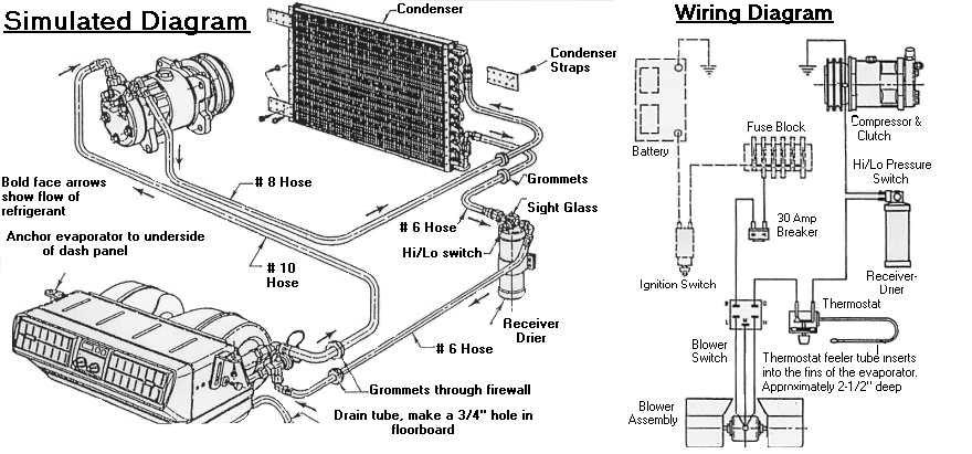
13 PAGE 12 A/C hose routing and installation: STEP SIX 1) The a/c hoses are to be crimped with an a/c hose-crimping tool. Most a/c stores and some auto parts stores have crimping tools. The hoses can be hooked up in any order you choose. The hose kit is a universal hose kit there will be left over fittings and hose when the job is done. The charge ports are normally attached to the compressor fittings. They do not have to be put on the compressor; it is up to the installer. Prior to having the hoses crimped together. Put the fittings on the hose with masking tape around each end to mark with a marker for clocking. Do not crimp the fittings over the tape. 2) Starting with the large hose #10 or ½. This hose goes from the large fitting on the compressor to the evaporator unit. The compressor will get the fitting with the charging port, low side. This hose will run through the firewall so be sure to use a grommet, 1-1/4 hole required. 3) The next size hose is #8 or 13/32. This hose runs from the compressor to the condenser. The compressor will get the fitting with the high side charging port. The condenser fitting connects to the fitting at the top of the condenser. When running the hose through or around the core support make sure it is protected with loom. A hole can be rubbed into the hoses if the hose is against metal edges. 4) The third and fourth hose to install is the # 6 or 5/16 hose. Start with the # 6 hose that runs from the bottom fitting on the condenser to the IN fitting on the drier. From the drier the hose will go through the firewall and grommet, 1-1/4 hole, to the expansion valve on the evaporator. After this hose is attached, place the black insulation tape over the fittings that are attached to the evaporator. Keep the #10 and #6 hoses close together when routing through the firewall, it makes the evaporator installation process easier. 5) The fittings included with the hose kit can be used in any manner necessary to run the hoses without kinking the lines. Make sure the hoses do not rub on metal edges without protection, and be sure to put O-rings on all the fitting connections. Oil is not necessary on the O-rings, it can be added to the threads on the fittings to stop them from seizing. DO NOT USE TEFLON TAPE. Tie the hoses down from flopping around, and keep the hoses off of the exhaust. 6) See the diagram at the end of the directions for hose routing.
14 PAGE 13 STEP SEVEN Installing the drain tube: 1) If the evaporator drain tube was not installed during step one you can do it now. This section serves as a reminder to install it. The drain tube goes from the drain outlets on the evaporator through the floorboard of the vehicle. The hole should be ¾ and the drain tube should be straight without any kinks. Do not let the drain hose rub on any sharp edges that can cut a hole in it. Charging the system: STEP EIGHT 1) DO NOT ADD OIL TO ANY PART OF THE SYSTEM. DO NOT USE DYE, LEAK SEALANTS, OR ALTERNATIVE REFRIGERANTS IN THE SYSTEM. We are not able to diagnose problems if the directions are not followed. 2) The system should be evacuated in order to achieve maximum cooling from the system. Evacuate the system for minutes. If the system is not evacuated the system may not cool properly. 3) After the system is evacuated and ready to charge, plug the compressor wire in. 4) When charging the system start with 1.5 LBS of R-134a refrigerant. The ideal pressures of the system are on the low side and on the high side. If the system is not within this range with 1.5lbs of R-134a add more R-134a in.25lb increments. If the high side gets high, and the low side stays low you have a condenser-cooling problem. Please see the first page.
15 PAGE 14
TOYOTA FJ-40 DIRECTIONS
 PAGE 1 TOYOTA FJ-40 DIRECTIONS Please read the following directions prior to installing this a/c system. Contact us by email or phone if you need any assistance or information regarding this a/c system.
Camaro A/C Install Instructions
 1967-1968 Camaro A/C Install Instructions This kit is designed for the 1967-1968 non A/C equipped Camaro. This kit can be used with or without Astro vents Step One Remove the following factory components:
JOHN DEERE GATOR HPX/XUV 2 PASSENGER HEATER INSTALLATION INSTRUCTIONS (p/n: 9PH20S30)
") P. 1 of 12 JOHN DEERE GATOR HPX/XUV 2 PASSENGER HEATER INSTALLATION INSTRUCTIONS (p/n: 9PH20S30) Item: Qty: Description: 1 2 1 x 1 x 5/8 Tee Fitting 2 2 Plastic Snap-in Hose Grommet 3 4 1-1/2" Hose Clamps
P. 1 of 12 JOHN DEERE GATOR HPX/XUV 2 PASSENGER HEATER INSTALLATION INSTRUCTIONS (p/n: 9PH20S30) Item: Qty: Description: 1 2 1 x 1 x 5/8 Tee Fitting 2 2 Plastic Snap-in Hose Grommet 3 4 1-1/2" Hose Clamps
Installation Manual Mopar Engine Compartment Upgrade Kit
 Installation Manual 64-75 Mopar Engine Compartment Upgrade Kit Congratulations... You have just purchased the highest quality, best performing A/C system upgrade ever designed for your Classic Vehicle.
PERFECT FIT IN-DASH HEAT/ COOL/ DEFROST PLYMOUTH BELVEDERE
 PERFECT FIT IN-DASH HEAT/ COOL/ DEFROST 1966-67 PLYMOUTH BELVEDERE CONTROL & OPERATING INSTRUCTIONS The controls on your new Perfect Fit system. Offers complete comfort capabilities in virtually every
PERFECT FIT IN-DASH HEAT/ COOL/ DEFROST 1968 CHEVROLET IMPALA
 specializing in AIR CONDITIONING, PARTS AND SYSTEMS for your classic vehicle PERFECT FIT IN-DASH HEAT/ COOL/ DEFROST 1968 CHEVROLET IMPALA CONTROL & OPERATING INSTRUCTIONS The controls on your new Perfect
an ISO 9001:2008 Registered Company GOLL ST. - SAN ANTONIO, TX ph fax MINI SPACE SAVER HEAT /COOL
 an ISO 9001:2008 Registered Company 18865 GOLL ST. - SAN ANTONIO, TX. - 78266 - ph.210-654-7171 - fax 210-654-3113 MINI SPACE SAVER HEAT /COOL 01000-QUX-A 01000-VUX-A 900101-VUX-A REV C 3/5/14, MINI SPACE
specializing in AIR CONDITIONING, PARTS AND SYSTEMS for your classic hi l PERFECT FIT SERIES IN-DASH HEAT/ COOL/ DEFROST FORD TRUCK
 specializing in AIR CONDITIONING, PARTS AND SYSTEMS for your classic hi l PERFECT FIT SERIES IN-DASH HEAT/ COOL/ DEFROST 1967-72 FORD TRUCK CONTROL & OPERATING INSTRUCTIONS The controls on your new Perfect
PERFECT FIT IN-DASH HEAT/ COOL/ DEFROST FORD PICKUP
 specializing in AIR CONDITIONING, PARTS AND SYSTEMS for your classic vehicle PERFECT FIT IN-DASH HEAT/ COOL/ DEFROST 1960-66 FORD PICKUP CONTROL & OPERATING INSTRUCTIONS The controls on your new Perfect
MINI SLIMLINE COOL VUY-A VUY-A
 an ISO 900:2008 Registered Company MINI SLIMLINE COOL 030-VUY-A 040-VUY-A 8865 GOLL ST. - SAN ANTONIO, TX. - 78266 ph.20-654-77 - fax 20-654-33 900302 REV D 0/28/4, MINI SLIMLINE COOL PG OF Table of Contents
PERFECT FIT SERIES IN-DASH HEAT/ COOL/ DEFROST CHEVROLET NOVA
 specializing in AIR CONDITIONING, PARTS AND SYSTEMS for your classic PERFECT FIT SERIES IN-DASH HEAT/ COOL/ DEFROST 1966-67 CHEVROLET NOVA CONTROL & OPERATING INSTRUCTIONS The controls on your new Perfect
an ISO 9001:2015 Registered Company
 an ISO 9001:2015 Registered Company Mark IV (672001-VHY) 18865 Goll St. San Antonio, TX 78266 Phone: 800-862-6658 Sales: sales@vintageair.com Tech Support: tech@vintageair.com www.vintageair.com 902001-VHY
PERFECT FIT IN-DASH HEAT/ COOL/ DEFROST EARLY 1955 CHEVROLET PICKUP
 specializing in AIR CONDITIONING, PARTS AND SYSTEMS for your classic vehicle PERFECT FIT IN-DASH HEAT/ COOL/ DEFROST 1947 - EARLY 1955 CHEVROLET PICKUP CONTROL & OPERATING INSTRUCTIONS The controls on
an ISO 9001:2008 Registered Company MINI SPACE SAVER HEAT /COOL/DEFROST QUZ-A VUZ-A
 an ISO 900:2008 Registered Company MINI SPACE SAVER HEAT /COOL/DEFROST 0000-QUZ-A 0000-VUZ-A 8865 GOLL ST. - SAN ANTONIO, TX. - 78266 - ph.20-654-77 - fax 20-654-33 90000-VUZ-A REV E 3/5/4, MINI SPACE
BC BRONCOS AIR CONDITIONING UNIT
 BC BRONCOS AIR CONDITIONING UNIT CAUTION If you are not familiar with the principals of air conditioning, have an authorized air conditioning technician evacuate and charge the system. Serious damage to
PERFECT FIT SERIES IN-DASH HEAT/ COOL/ DEFROST CHEVROLET CHEVELLE/ EL CAMINO NOTE: INSTRUCTIONS DEPICT CHEVELLE
 specializing in AIR CONDITIONING, PARTS AND SYSTEMS for your classic vehicle PERFECT FIT SERIES IN-DASH HEAT/ COOL/ DEFROST 1964-65 CHEVROLET CHEVELLE/ EL CAMINO NOTE: INSTRUCTIONS DEPICT CHEVELLE CONTROL
PERFECT FIT SERIES IN-DASH HEAT/ COOL/ DEFROST MUSTANG
 specializing in AIR CONDITIONING, PARTS AND SYSTEMS for your classic vehicle PERFECT FIT SERIES IN-DASH HEAT/ COOL/ DEFROST 1965-66 MUSTANG CONTROL & OPERATING INSTRUCTIONS The controls on your new Perfect
ULTIMATE A/C BANTAM SYSTEM. INSTALLATION INSTRUCTIONS 2019 RestomodAir / 03.19
 ULTIMATE A/C BANTAM SYSTEM INSTALLATION INSTRUCTIONS 2019 RestomodAir / 03.19 ULTIMATE A/C BANTAM SYSTEM Congratulations, you ve got a Bantam... the highest performing, compact A/C in the aftermarket.
COMPAC GEN II HEAT/COOL VUX-A. an ISO 9001:2008 Registered Company #10 SUCTION HOSE COMPRESSOR #8 DISCHARGE HOSE EVAPORATOR DRIER CONDENSER
 an ISO 900:2008 Registered Company COMPAC GEN II HEAT/COOL 68000-VUX-A EVAPORATOR #0 SUCTION HOSE COMPRESSOR #8 DISCHARGE HOSE DRIER #6 LIQUID LINE CONDENSER 90680-VUX-A REV E 2/28/4, INST. GEN II COMPAC
an ISO 9001:2008 Registered Company ShortPac HEAT/COOL (05000-QUX-A/05000-VUX-A)
") an ISO 9001:2008 Registered Company ShortPac (05000-QUX-A/05000-VUX-A) 18865 GOLL ST. - SAN ANTONIO, TX. - 78266 - ph.210-654-7171 - fax 210-654-3113 900499 REV C 3/7/14, ShortPac EVAPORATOR KIT PG 1 OF
an ISO 9001:2008 Registered Company ShortPac (05000-QUX-A/05000-VUX-A) 18865 GOLL ST. - SAN ANTONIO, TX. - 78266 - ph.210-654-7171 - fax 210-654-3113 900499 REV C 3/7/14, ShortPac EVAPORATOR KIT PG 1 OF
Attach the drain tube through the hole.
 HEATER ONLY AND FACTORY A/C CARS Reinstall the centre bezel using original hardware. Check for the seal around the centre louver as to not block the air. HEATER CARS A/C CARS The drivers side ball louver
Heavy Duty Heater / Air Conditioner Model R-8545
 Heavy Duty Heater / Air Conditioner Model R-8545 INSTALLATION INSTRUCTIONS NOTE 1. Please read instructions all the way through, making sure you have all the parts and tools 2. While working on or around
HEAT/ COOL/ DEFROST FORD THUNDERBIRD
 specializing in AIR CONDITIONING, PARTS AND SYSTEMS for your classic vehicle PERFECT FIT IN-DASH HEAT/ COOL/ DEFROST 1964-66 FORD THUNDERBIRD CONTROL & OPERATING INSTRUCTIONS The controls on your new Perfect
SUPER GEN II HEAT/COOL VUX-A. an ISO 9001:2008 Registered Company EVAPORATOR #10 SUCTION HOSE COMPRESSOR #8 DISCHARGE HOSE DRIER CONDENSER
 an ISO 900:2008 Registered Company SUPER GEN II HEAT/COOL 6005-VUX-A EVAPORATOR #0 SUCTION HOSE COMPRESSOR #8 DISCHARGE HOSE DRIER #6 LIQUID LINE CONDENSER 90606-VUX-A REV E 2/28/4, INST. GEN II SUPER
Installation Manual Mustang DOCUMENT # ClassicAutoAir / 3.12vs.a
 Installation Manual 1971-1973 Mustang DOCUMENT #1-2028 2012 ClassicAutoAir / 3.12vs.a CAA 2028 Installation.indd 1 Congratulations... You have just purchased the highest quality, best performing A/C system
A/C-HEATER SYSTEM - MANUAL
 A/C-HEATER SYSTEM - MANUAL 1986 Isuzu Trooper II 1986 A/C-HEATER SYSTEM Isuzu A/C-Heater Systems - Manual P UP, Trooper II * PLEASE READ THIS FIRST * CAUTION: When discharging air conditioning system,
Kawasaki Teryx Firestorm Heater Kit Instructions.
 Please read all instructions before beginning installation. When working on cooling systems always allow vehicles to cool to avoid being burned or scalded by hot coolant. Always disconnect vehicle s negative
1956 FORD F-100 TRUCK
 an ISO 9001:2008 Registered Company INSTALLATION INSTRUCTIONS FOR 1956 FORD F-100 TRUCK HEAT/COOL/DEFROST 75456-LFZ-A 18865 GOLL ST. - SAN ANTONIO, TX. - 78266 - ph.210-654-7171 - fax 210-654-3113 905456-LFZ-A
Installation Manual Mustang
 Installation Manual 1971-1973 Mustang DOCUMENT #1-2028 2013 ClassicAutoAir / 2-1vs.b Congratulations... You have just purchased the highest quality, best performing A/C system ever designed for your Classic
Chevrolet Corvette Auxiliary Electric Condenser Fan Kit with Trinary Switch ( CCA)
") an ISO 900:2008 Registered Company 968-76 Chevrolet Corvette Auxiliary Electric Condenser Fan Kit with Trinary Switch (302686-CCA) 8865 Goll St. San Antonio, TX 78266 Phone: 800-862-6658 Sales: sales@vintageair.com
an ISO 900:2008 Registered Company 968-76 Chevrolet Corvette Auxiliary Electric Condenser Fan Kit with Trinary Switch (302686-CCA) 8865 Goll St. San Antonio, TX 78266 Phone: 800-862-6658 Sales: sales@vintageair.com
INSTALLATION AND COMMISSIONING MANUAL. Neos 100S Integra 20X, 30S, 35X, 40X, 50X
 Installation Truck Refrigeration & Commissioning Manual: INSTALLATION AND COMMISSIONING MANUAL for Neos 100S Integra 20X, 30S, 35X, 40X, 50X Direct Drive Refrigeration Units 2017 Carrier Corporation Printed
WELCH INDUSTRIES - PAGE 1 OF 5
 MCI 9, 96A & 102 RE-2 Auxiliary Installation Look over all components in order to familiarize yourself with the complete system. The compressor mounts over the gear-box between radiators, driven by the
R-2000 HEADLINER Air Conditioner Unit
 RED DOT UNITS ON ROAD R-2000 HEADLINER Air Conditioner Unit TRUCKS MOTOR HOMES VANS REFUSE The compact, low profile design of the R-2000 allows an out of the way ceiling mount in virtually any vehicle.
1969 Camaro DOCUMENT # ClassicAutoAir / 3.12vs.a
 1969 Camaro DOCUMENT #1-2056 2012 ClassicAutoAir / 3.12vs.a Congratulations... You have just purchased the highest quality, best performing A/C system ever designed for your Classic Vehicle. To obtain
INSTALLATION INSTRUCTIONS PT-A HEAT/AC STANDARD KIT FORD E-SERIES VANS
 INSTALLATION INSTRUCTIONS PT-A-402 - HEAT/AC STANDARD KIT 2007-2014 FORD E-SERIES VANS with Gas engine (To be used with 2007 and newer Prisoner Transport Inserts ONLY) Warning do not attempt to install
Ford Falcon, Ranchero Condenser Kit with Drier (014150)
") an ISO 900:2008 Registered Company 964-65 Ford Falcon, Ranchero Condenser Kit with Drier (0450) 8865 Goll St. San Antonio, TX 78266 Phone: 20-654-77 Fax: 20-654-33 www.vintageair.com 903250 REV A 06/23/5,
an ISO 900:2008 Registered Company 964-65 Ford Falcon, Ranchero Condenser Kit with Drier (0450) 8865 Goll St. San Antonio, TX 78266 Phone: 20-654-77 Fax: 20-654-33 www.vintageair.com 903250 REV A 06/23/5,
Heater with Air Conditioning. E-Series Ford Aeromaster
 Service Guide Heater with Air Conditioning E-Series Ford Aeromaster Contents Blower Motor...2 Plenum Removal...3 Control Module...6 Servo Motors...8 Coolant Valve and Servo Motor...8 Evaporator Recirculation
an ISO 9001:2008 Registered Company
 an ISO 900:2008 Registered Company 964-67 Pontiac GTO Condenser Kit without Drier (02676) Please Note: Installation for 964 Models is covered on Pages 4-8 Installation for 965-67 Models is covered on Pages
INSTALLATION INSTRUCTIONS John Deere One Series; 1023E, 1025R and 1026R Models A HEATER KIT. Figure 1 (General Layout and Parts I.D.
 A-11978 HEATER KIT Figure 1 (General Layout and Parts I.D.) Read these instructions and identify all components. Please retain these instructions for future reference and parts ordering information. Refer
Toyota FJ40 Evaporator Upgrade Add-On Kit (751202)
") an ISO 900:2008 Registered Company 968-83 Toyota FJ40 Evaporator Upgrade Add-On Kit (75202) TOYOTA 8865 Goll St. San Antonio, TX 78266 Phone: 800-862-6658 Sales: sales@vintageair.com Tech Support: tech@vintageair.com
an ISO 900:2008 Registered Company 968-83 Toyota FJ40 Evaporator Upgrade Add-On Kit (75202) TOYOTA 8865 Goll St. San Antonio, TX 78266 Phone: 800-862-6658 Sales: sales@vintageair.com Tech Support: tech@vintageair.com
Chevrolet Chevelle Condenser Kit with Drier (021166)
") an ISO 900:008 Registered Company 964-67 Chevrolet Chevelle Condenser Kit with Drier (066) SS 8865 Goll St. San Antonio, TX 7866 Phone: 0-654-77 Fax: 0-654-33 www.vintageair.com 90366 REV D 08//5, PG OF
an ISO 900:008 Registered Company 964-67 Chevrolet Chevelle Condenser Kit with Drier (066) SS 8865 Goll St. San Antonio, TX 7866 Phone: 0-654-77 Fax: 0-654-33 www.vintageair.com 90366 REV D 08//5, PG OF
SEA FROST SHORE ASSIST SA-1 R-12 THIS MANUAL IS SUPPLEMENTAL TO THE SEA FROST R-12 ENGINE DRIVE MANUAL INSTALLATION INSTRUCTIONS
 148 OLD CONCORD TURNPIKE BARRINGTON, NH 03825 USA TEL (603) 868-5720 FAX (603) 868-1040 1-800-435-6708 E-Mail:sales@seafrost.com www.seafrost.com SEA FROST SHORE ASSIST SA-1 R-12 THIS MANUAL IS SUPPLEMENTAL
Heating and ventilation system,
 Page 1 of 24 87-151 Heating and ventilation system, servicing Instrument panel air outlets and air guide ducts CAUTION! Before working on the electrical system: Obtain security code for anti-theft radio.
A HEATER KIT With Diesel Engine Connection Fittings
 A-12142 HEATER KIT With Diesel Engine Connection Fittings Figure 1 (General Layout and Parts I.D.) Page 1 of 6 Read these instructions and identify all components. Please retain these instructions for
Performance Automotive Air Conditioning
 Performance Automotive Air Conditioning The Basics 18865 GOLL ST. - SAN ANTONIO, TX. - 78266 ph.210-654-7171 - fax 210-654-3113 The Basics of Performance Air Conditioning 1. Primary purpose of air conditioning
This site is based on a but applies to all 1971-on Saab 99 and Saab 900.
 by Mark Jeter updated: December 8, 2004 originally web-published June 27, 2001 This document shows how the original waterpump in a Saab "B" engine can be eliminated and replaced with a reliable, efficient
Chevrolet Pickup Condenser Kit with Drier with Condenser Mounted Forward From Stock Position (021553)
") an ISO 900:2008 Registered Company 97-55 Chevrolet Pickup Condenser Kit with Drier with Condenser Mounted 3 8 Forward From Stock Position (02553) 8865 Goll St. San Antonio, TX 78266 Phone: 20-65-77 Fax:
an ISO 900:2008 Registered Company 97-55 Chevrolet Pickup Condenser Kit with Drier with Condenser Mounted 3 8 Forward From Stock Position (02553) 8865 Goll St. San Antonio, TX 78266 Phone: 20-65-77 Fax:
2002 Dodge Caravan SE
 EVAPORATOR (FRONT) Removal 1. Remove the HVAC housing from the vehicle. See HVAC HOUSING (FRONT). Remove the heater hoses from the heater core. 2. Remove and discard the foam seal from the HVAC housing
ENSPECO Recovery/ Recycle/ Evacuate/ Recharge
 ENSPECO Recovery/ Recycle/ Evacuate/ Recharge RMS 3012 RMS 3034 Approved by UL/SAE to J-1991 R12 Purity Standards Approved by UL/SAE to J-2210 R134 Purity Standards This semi-automatic machine will recover
Installation Instructions. For the 18 Built-In Dishwasher and Front Color Panels
 Installation Instructions For the 18 Built-In Dishwasher and Front Color Panels Printed in USA 154232102 Before You Begin DO NOT INSTALL DISHWASHER UNTIL YOU HAVE READ ALL INSTRUCTIONS. FOR YOUR SAFETY,
an ISO 9001:2008 Registered Company
 an ISO 900:2008 Registered Company 964-67 Pontiac GTO Condenser Kit with Drier (0206) Please Note: Installation for 964 Models is covered on Pages 4-3 Installation for 965-67 Models is covered on Pages
Chevrolet Impala Condenser Kit with Drier (021062)
") an ISO 900:2008 Registered Company 96-63 Chevrolet Impala Condenser Kit with Drier (02062) 8865 Goll St. San Antonio, TX 78266 Phone: 20-654-77 Fax: 20-654-33 www.vintageair.com 90063 REV D 03/22/6, PG
an ISO 900:2008 Registered Company 96-63 Chevrolet Impala Condenser Kit with Drier (02062) 8865 Goll St. San Antonio, TX 78266 Phone: 20-654-77 Fax: 20-654-33 www.vintageair.com 90063 REV D 03/22/6, PG
CIRRUS AIRPLANE MAINTENANCE MANUAL
 COOLING 1. DESCRIPTION On aircraft serials 183 and subsequent, an optional air condition system is available. This section contains the maintenance practices pertinent to this system. Cabin ventilation
INSTALLATION & OWNER S MANUAL
 Rev. A, p. 1 of 8 INSTALLATION & OWNER S MANUAL HONDA PIONEER 700-2 AND 700-4 HEATER INSTALLATION p/n: 9PH20S64 The contents of this envelope are the property of the owner. Be sure to leave with the owner
MANUAL CONTROL HEATING, VENTILATION, AND AIR CONDITIONING SYSTEM
 SECTION 7B MANUAL CONTROL HEATING, VENTILATION, AND AIR CONDITIONING SYSTEM CAUTION: Disconnect the negative battery cable before removing or installing any electrical unit or when a tool or equipment
TOOLS REQUIRED: Crimping tool A/C Recovery Unit Wrench set up to 1 ¼ 4 Hole saw
 INSTALL INSTRUCTIONS PT-A-401 HVAC UNIT for 2003-2018 CHEVROLET/GMC VAN (For 2007 ALL WHITE Prisoner Transport Inserts ONLY) Not Recommended for diesel engine application because of lack of space needed
HEATING AND AIR CONDITIONING
 WJ HEATING AND AIR CONDITIONING 24-1 HEATING AND AIR CONDITIONING TABLE OF CONTENTS page SERVICE PROCEDURES REFRIGERANT OIL LEVEL...1 REFRIGERANT RECOVERY....1 REFRIGERANT SYSTEM CHARGE...1 REFRIGERANT
OWNER S MANUAL CAVN SERIES SELF CONTAINED RETRACTABLE NOZZLE VACUUM SEALER WITH GAS PURGE
 OWNER S MANUAL CAVN SERIES SELF CONTAINED RETRACTABLE NOZZLE VACUUM SEALER WITH GAS PURGE WHAT S IN THE PACKAGE? This Operation Manual. (1) Vacuum Sealer. (1) E-(unit size) Heating Element, inside the
1964 ½-66 Ford Mustang Condenser Kit with Drier with Driver Side Connections (011065)
") an ISO 900:2008 Registered Company 964 ½-66 Ford Mustang Condenser Kit with Drier with Driver Side Connections (0065) *For Use With: Standard Hose Kit 5268 Modified Hose Kit 56268 8865 Goll St. San Antonio,
an ISO 900:2008 Registered Company 964 ½-66 Ford Mustang Condenser Kit with Drier with Driver Side Connections (0065) *For Use With: Standard Hose Kit 5268 Modified Hose Kit 56268 8865 Goll St. San Antonio,
SPX SERIES PACKAGED AIR CONDITIONING/HEAT PUMP UNITS INSTALLATION, OPERATION AND MAINTENANCE INSTRUCTIONS
 SPX SERIES PACKAGED AIR CONDITIONING/HEAT PUMP UNITS INSTALLATION, OPERATION AND MAINTENANCE INSTRUCTIONS **WARNING TO INSTALLER, SERVICE PERSONNEL AND OWNER** Altering the product or replacing parts with
π H-2268 SANITAIRE UPRIGHT VACUUM SAFETY uline.com
 π H-2268 SANITAIRE UPRIGHT VACUUM 1-800-295-5510 uline.com SAFETY PAGE 1 OF 7 NOTE: When using an electrical appliance, basic precautions should always be followed, including the following: READ ALL INSTRUCTIONS
Chevrolet Camaro Condenser Kit with Drier (021179)
") an ISO 900:008 Registered Company 978-8 Chevrolet Camaro Condenser Kit with Drier (079) 8865 Goll St. San Antonio, TX 7866 Phone: 0-65-77 Fax: 0-65-33 www.vintageair.com 9085 REV C 03/8/6, PG OF 3 Table
an ISO 900:008 Registered Company 978-8 Chevrolet Camaro Condenser Kit with Drier (079) 8865 Goll St. San Antonio, TX 7866 Phone: 0-65-77 Fax: 0-65-33 www.vintageair.com 9085 REV C 03/8/6, PG OF 3 Table
Installation Manual. Truck Edition V-520 RT Series Model 10, 20, 30 and 50 Single Temperature Systems. TK IM (Rev.
 Installation Manual Truck Edition V-520 RT Series Model 10, 20, 30 and 50 Single Temperature Systems TK 54987-1-IM (Rev. 2, 03/12) Installation Manual Truck Edition V-520 RT Series Models 10, 20, 30 and
HEATING AND AIR CONDITIONING
 PL HEATING AND AIR CONDITIONING 24-1 HEATING AND AIR CONDITIONING TABLE OF CONTENTS page REMOVAL AND INSTALLATION EVAPORATOR CORE R. H. D....1 HEATERCORE R.H.D...3 page SPECIFICATIONS TORQUE SPECIFICATIONS...6
CABS/BLADES/ SPREADERS/ACCESSORIES
 JOHN DEERE 3000 SERIES (4200/4300/4400) (4210/4310/4410) (3120/3320/3520/3720) JOHN DEERE 4000 SERIES (4500/4600/4700) (4510/4610/4710) (4120/4320/4520/4720) OPTIONAL AUXILIARY HEATER INSTALLATION (p/n
1. SAFETY RULES WARNING WARNING. 8. Avoid placing objects in the path of the blades.
 1 1. SAFETY RULES 1. To reduce the risk of electric shock, insure electricity has been turned off at the circuit breaker or fuse box before beginning. 2. All wiring must be in accordance with the National
PRELIMINARY INSTALLATION. Operation & Service Manual. Carrier Transicold Europe 03/09/07 Viento - Installation/Rev- #1/56
 INSTALLATION Carrier Transicold Europe 03/09/07 Viento - Installation/Rev- #1/56 INSTALLATION Table of content Introduction...4 Preparation before installation...5 Vehicle partition... 6 Box preparation...7
 Section 12-00: Climate Control System Service 1997 Town Car Workshop Manual DIAGNOSIS AND TESTING Procedure revision date: 06/29/2000 Climate Control System Inspection and Verification 1. Verify the customer's
INSTALLATION INSTRUCTIONS
 INSTALLATION INSTRUCTIONS Accessory Application Publication No. HEATER KIT P/N 0SE01-HL3-102 (SXS700M2/M4) P/N 0SE01-HL3-103 (SXS700M2D/M4D) SXS700M2/M2D/M4/M4D MII 14607-15172 Issue Date REVISED: June
GETZ EQUIPMENT INNOVATORS PART NO.: 9G58619 MODEL: SV1 150 PR VACUFILL SYSTEM (Revised 2/25/14)
") GETZ EQUIPMENT INNOVATORS PART NO.: 9G58619 MODEL: SV1 150 PR VACUFILL SYSTEM (Revised 2/25/14) !!WARNING!! SEVERE DAMAGE AND/OR INJURY MAY RESULT DO NOT DISCHARGE ANY EXTINGUISHER CYLINDER EXCEEDING 195
GETZ EQUIPMENT INNOVATORS PART NO.: 9G58619 MODEL: SV1 150 PR VACUFILL SYSTEM (Revised 2/25/14) !!WARNING!! SEVERE DAMAGE AND/OR INJURY MAY RESULT DO NOT DISCHARGE ANY EXTINGUISHER CYLINDER EXCEEDING 195
Warning Do not attempt to install A/C units unless you are experienced with servicing A/C systems! Wire Cutter / Crimper Socket set
 INSTALLATION INSTRUCTIONS PT-A-405 Rear HVAC System for 2014-2018 RAM PROMASTER with OEM rear AC/Heat Prep Package Fittings For Installation with Havis Prisoner Transport Insert Warning Do not attempt
INSTALLATION INSTRUCTIONS
 Accessory Application Publication No. INSTALLATION INSTRUCTIONS HEATER KIT P/N 0SE01-HL3-101 SXS700M4/M2 Honda Dealer: Please give a copy of these instructions to your customer. PARTS LIST REPAIR KIT (P/N
R-8725/R-8730 Underdash Drop In Evaporator
 RED DOT UNITS HEATER-A/C FORD R-8725/R-8730 Underdash Drop In Evaporator FOR FORD L SERIES The R-8725/R-8730 drop-in evaporator kit takes advantage of the OEM housing and blower motor assembly. Includes
Enspeco RMS. The Enspeco Refrigerant Management. The following instructions will INSTRUCTIONS
 Enspeco AUTOMOTIVE REFRIGERANT MANAGEMENT SYSTEMS RMS 5000 INSTRUCTIONS The Enspeco Refrigerant Management System 5000 provides fast and efficient recovery, recycling and charging of automotive air conditioning
GENERAL 2004 HVAC SYSTEMS. Manual HVAC System - Sorento SPECIFICATIONS. Fig. 1: Air Conditioner Specifications Courtesy of KIA MOTORS AMERICA, INC.
 Fig. 2: Blower & Evaporator Unit Specifications 2004 HVAC SYSTEMS Manual HVAC System - Sorento GENERAL SPECIFICATIONS AIR CONDITIONER Fig. 1: Air Conditioner Specifications BLOWER AND EVAPORATOR UNIT HEATER
1 of 5 6/28/17, 1:54 PM
 1 of 5 6/28/17, 1:54 PM Procedure A Use this procedure if there is sufficient clearance to insert the drain hose past the brake pipes. If clearance is restricted, go to Procedure B. ENDEAVOR FWD 1. Open
Product Support Bulletin
 MODEL: SUBJECT: CONVENTIONAL, W/ C7 CAT ENGINE WEBASTO TSL-17 HEATER Body DATE: APRIL 13, 2004 INDEX: 6 PAGE: 1 OF 16 Before you start this procedure, perform Freightliner Service Bulletin #20-7 first.
42 Kevlar. Instruction Manual. Kichler Lighting 7711 East Pleasant Valley Road P.O. Box Cleveland, Ohio
 42 Kevlar Kichler Lighting 7711 East Pleasant Valley Road P.O. Box 318010 Cleveland, Ohio 44131-8010 Customer Service 866.558.5706 8:30 AM to 5:00 PM EST, Monday - Friday Instruction Manual 1 1. SAFETY
TOP AND CONSOLE PARTS
 TOP AND CONSOLE PARTS 27" ELECTRIC DRYER 6 12 Printed in U.S.A. (GG)(bay) 1 Part No. Rev. A TOP AND CONSOLE PARTS 1 Literature Parts W10392124 Installation, Diagnostic Guide W10388780 Guide, Use & Care
Chevrolet Pickup Evaporator Kit (754563)
") an ISO 9001:2008 Registered Company 1954-55 Chevrolet Pickup Evaporator Kit (754563) 18865 Goll St. San Antonio, TX 78266 Phone: 210-654-7171 Fax: 210-654-3113 www.vintageair.com 905459 REV B 10/05/15,
an ISO 9001:2008 Registered Company 1954-55 Chevrolet Pickup Evaporator Kit (754563) 18865 Goll St. San Antonio, TX 78266 Phone: 210-654-7171 Fax: 210-654-3113 www.vintageair.com 905459 REV B 10/05/15,
60" Tulle PatioTM. Instruction Manual. A Kichler Select ceiling fan
 60" Tulle PatioTM A Kichler Select ceiling fan cul Certified for Wet Location Kichler Lighting 7711 East Pleasant Valley Road P.O. Box 318010 Cleveland, Ohio 44131-8010 Customer Service 866.558.5706 8:30
OWNER S MANUAL CAVS SERIES SELF CONTAINED RETRACTABLE NOZZLE VACUUM SEALER
 OWNER S MANUAL CAVS SERIES SELF CONTAINED RETRACTABLE NOZZLE VACUUM SEALER WHAT S IN THE PACKAGE? This Operation Manual. (1) Vacuum Sealer. (1) E-(unit size) Heating Element, inside the manual sheet protector.
Mopar B-Body Condenser Kit with Drier
 an ISO 900:2008 Registered Company 966-70 Mopar B-Body Condenser Kit with 05066 Fits: Plymouth: Belvedere, Satellite, Road Runner (Except 970), GTX Dodge: Charger (Except 966-67), Coronet, Super Bee 8865
an ISO 9001:2008 Registered Company CORVETTE REV A 11/1/10, COVETTE EVAP INST PG 1 OF 24
 an ISO 9001:2008 Registered Company 1961-62 CORVETTE 561060 901047 REV A 11/1/10, 61-62 COVETTE EVAP INST PG 1 OF 24 Table of Contents PAGES 1. COVER 2. TABLE OF CONTENTS 3. PACKING LIST / PARTS DISCLAIMER
Installation Instructions
 Installation Instructions For Fully Integrated NoFrost Combined Refrigerator-Freezers HC 2060/2061 HCB 2060/2061 7084 349-00 Important Please Read and Follow these Instructions These instructions contain
Installation Instructions
 Installation Instructions Before you begin... 2 Location... 2 Recommended grounding instructions... 2 Electrical requirements... 2 Exhaust requirements... 3 Water supply and drain requirements... 3 Please
Installation Instructions T 9822 Gas Dryer. en - US, CA. To prevent accidents
 Installation Instructions T 9822 Gas Dryer To prevent accidents en - US, CA and appliance damage read these instructions before installation or use. M.-Nr. 07 431 110 2 WARNING For your safety the information
Installation instructions for the T 9820 Gas Dryer
 Installation instructions for the T 9820 Gas Dryer The T 9820 gas dryer is only approved for use in the USA and Canada. It is not approved for use in Mexico. To prevent accidents en - US, CA and machine
Hoshizaki America, Inc.
 Hoshizaki America, Inc. Stackable Crescent Cuber Models KM-1301SAH/3 KM-1301SWH/3 KM-1301SRH/3 A Superior Degree of Reliability INSTRUCTION MANUAL www.hoshizaki.com Issued: 9-4-2008 Revised: 2-5-2013 IMPORTANT
OWNER S MANUAL AVN SERIES RETRACTABLE NOZZLE VACUUM SEALER WITH GAS PURGE
 OWNER S MANUAL AVN SERIES RETRACTABLE NOZZLE VACUUM SEALER WITH GAS PURGE WHAT S IN THE PACKAGE? This Operation Manual. (1) Vacuum Sealer. (1) E-(unit size) Heating Element, inside the manual sheet protector.
Homestyle Stacked Washer/ Dryer
 Homestyle Stacked Washer/ Dryer Parts Refer to Page 3 for Model Numbers SWD441C_801998 www.alliancelaundry.com Part No. 801998R6 January 2018 Table of Contents Title Page Parts Ordering Information...
Truck Edition V-520 RT Series Models 10, 20, 30 and 50 Single Temperature Systems TK IM (Rev. 8, 1/16)
") Installation Manual Truck Edition V-520 RT Series Models 10, 20, 30 and 50 Single Temperature Systems TK 54987-18-IM (Rev. 8, 1/16) Installation Manual Truck Edition V-520 RT Series Models 10, 20, 30
Installation Manual Truck Edition V-520 RT Series Models 10, 20, 30 and 50 Single Temperature Systems TK 54987-18-IM (Rev. 8, 1/16) Installation Manual Truck Edition V-520 RT Series Models 10, 20, 30
SEA FROST BD 12 OR 24-VOLT D.C. AIR-COOLED SYSTEM
 148 OLD CONCORD TURNPIKE BARRINGTON, NH 03825 USA TEL (603) 868-5720 FAX (603) 868-1040 1-800-435-6708 E-Mail:sales@seafrost.com www.seafrost.com SEA FROST BD 12 OR 24-VOLT D.C. AIR-COOLED SYSTEM CONDENSING
2000 Crown Victoria/Grand Marquis Workshop Manual
 SECTION 412-02: Heating and Ventilation 2000 Crown Victoria/Grand Marquis Workshop Manual REMOVAL AND INSTALLATION Procedure revision date: 06/21/1999 Evaporator Core Housing Removal 1. Disconnect the
Home Stack Washer/Dryers
 Home Stack Washer/Dryers Refer to Page 3 for Model Numbers Parts SWD456C_806093 www.alliancelaundry.com Part No. 806093R1 December 2016 Table of Contents Title Page Parts Ordering Information... 2 Serial
TABLE OF CONTENTS Contact Information:
 TABLE OF CONTENTS Contact Information: INTRODUCTION BEFORE YOU USE YOUR OWNER S MANUAL, PLEASE READ THIS INTRODUCTION ALL THE WAY THROUGH. WHEN THE MACHINE IS DELIVERED: BEFORE OPERATING THE MACHINE: WARRANTY:
WB Holden Aircondtioning Re-Instalation
 WB Holden Aircondtioning Re-Instalation My Ute has the rudimentary remains of the Airconditioning System in the form of the Evaporator/Heater airbox mounted forward and aft of the firewall. The original
Component. Maintenance. Manual Z SERIES. Evaporator Assembly
 Component Maintenance Manual with Illustrated Parts List for Z21-701-SERIES Evaporator Assembly 1 of 16 Record of Revision REVISION ISSUE POSTED NO: DATE DATE INSERTED BY: 2 of 16 List of Effective Pages
Home Stacked Washer/Dryer
 Home Stacked Washer/Dryer Refer to Page 3 for Model Numbers Parts SWD443C_802107 www.comlaundry.com Part No. 802107R6 August 2014 Table of Contents Title Page Parts Ordering Information... 2 Serial Plate
1. SAFETY RULES. 8. Avoid placing objects in the path of the blades.
 1 1. SAFETY RULES 1. To reduce the risk of electric shock, insure electricity has been turned off at the circuit breaker or fuse box before beginning. 2. All wiring must be in accordance with the National