Operating manual. Recirculating Coolers. English
|
|
|
- Bennett Sanders
- 5 years ago
- Views:
Transcription
1 RS232 ALARM C English Operating manual Recirculating Coolers FL2503 FL2506 FL4003 FL4006 FLW2503 FLW2506 FLW4003 FLW4006 FL V2 10/13 JULABO GmbH Seelbach / Germany Tel. +49 (0) 7823 / 51-0 Fax +49 (0) 7823 / info@julabo.de V2.doc Print date:

2 Congratulations! You have made an excellent choice. JULABO thanks you for the trust you have placed in us. This operating manual has been designed to help you gain an understanding of the operation and possible applications of our circulators. For optimal utilization of all functions, we recommend that you thoroughly study this manual prior to beginning operation. The JULABO Quality Management System Temperature control devices for research and industry are developed, produced, and distributed according to the requirements of ISO 9001 and ISO Certificate Registration No Unpacking and inspecting Unpack the recirculating cooler and accessories and check for damages incurred during transit. These should be reported to the responsible carrier, railway, or postal authority, and a request for a damage report should be made. These instructions must be followed fully for us to guarantee our full support of your claim for protecting against loss from concealed damage. The form required for filing such a claim will be provided by the carrier. Lifting device for transportation by crane see page 20 Printed in Germany Changes without prior notification reserved Important: keep operating manual for future use 2
3 TABLE OF CONTENTS 1. Intended use Description Operator responsibility Safety instructions Disposal EC Conformity Technical specifications Cooling water connection Safety notes for the user Explanation of safety notes Explanation of other notes Safety instructions Installation Tubing Operating controls and functional elements Operating procedures Bath fluids Power connection Filling Switching on / Start - Stop Setting the feed pressure Setting the temperatures AUTOSTART ON / OFF Remote control: activate deactivate Safety installations Excess temperature protection Low level protection Troubleshooting guide / Error messages Electrical connections Remote control Setup for remote control Communication with a PC or a superordinated data system List of commands Status messages Error messages Cleaning / repairing the unit JULABO Service Online remote diagnosis Draining Adequate storing of operating manual Warranty conditions
4 1. Intended use JULABO recirculating coolers have been designed for temperature application to specific fluids. The pump connections can be used for cooling applications in an external circuit at a constant temperature. JULABO water baths are not suitable for direct temperature control of foods, semiluxury foods and tobacco, or pharmaceutical and medical products. Direct temperature control means unprotected contact of the object with the bath medium (bath fluid) Description The recirculating coolers are operated via the splash-proof keypad. The implemented microprocessor technology allows to set and to store the setpoint that can be indicated on the LED temperature display. The PID temperature regulation is used to withdraw heat from the bath fluid by means of the cooling machine and to automatically regulate the required need. PID1 RS232 Electrical connections: 1. The serial interface RS232 allows modern process technology without additional interface. 2. Alarm output for external alarm message. Manually adjustable by-pass (handwheel) to reduce the pump capacity (e. g. for glass equipment). 2. Operator responsibility Safety instructions The products of JULABO ensure safe operation when installed, operated, and maintained according to common safety regulations. This section explains the potential dangers that may arise when operating the circulator and also specifies the most important safety precautions to preclude these dangers as far as possible. The operator is responsible for the qualification of the personnel operating the units. The personnel operating the units should be regularly instructed about the dangers involved with their job activities as well as measures to avert these dangers. Make sure all persons tasked with operating, installing, and maintaining the unit have read and understand the safety information and operating instructions. When using hazardous materials or materials that could become hazardous, the unit may be operated only by persons who are absolutely familiar with these materials and the unit. These persons must be fully aware of possible risks. If you have any questions concerning the operation of your unit or the information in this manual, please contact us! Contact JULABO GmbH Eisenbahnstraße Seelbach / Germany Tel info@julabo.de Fax
 or contamination. Make sure the product is regularly checked for proper condition.")
5 Safety recommendations for the operator You received a product conceived for industrial use. Nevertheless, avoid strikes to the housing, vibrations, damages to the keypad foil (keys, display) or contamination. Make sure the product is regularly checked for proper condition. Regularly check (at least every 2 years) the proper condition of the mandatory, warning, prohibition and safety labels. Take care that the mains supply features a low impedance to avoid any negative affects on the instrument being operated in the same mains. This unit is designed for operation in a controlled electromagnetic environment. This means that transmitting devices (e.g. cellular phones) should not be used in the immediate vicinity. Magnetic radiation may influence other units with components susceptible to magnetic fields (e.g. a monitor). We recommend to keep a minimum distance of 1 m. Permissible ambient temperature: max. 40 C, min. 5 C. Permissible relative air humidity: 50 % (40 C). Do not store in an aggressive atmosphere. Protect from contaminations. Do not expose to sunlight. Appropriate Operation Only qualified personnel is authorized to perform configuration, installation, maintenance and repairs of the water bath. Routine operation can also be carried out by untrained personnel who should however be instructed by trained personnel. Use For the use according to the intended purpose, special material requirements have to be respected (bath fluids). Only use non-acid and non corroding materials. Observe all warnings for the used materials (bath fluids) and the respective instructions (safety data sheets). Only use the unit in well ventilated areas. (see page 16). The recirculating coolers are not for use in explosive atmosphere When using hazardous materials or materials that could become hazardous, the operator must affix the enclosed safety labels (1 + 2) to the front of the unit so they are highly visible: 1 Warning label W00: Colors: yellow, black Danger area. Attention! Observe instructions. (operating manual, safety data sheet) 2 or Mandatory label M018: Colors: blue, white Carefully read the user information prior to beginning operation. Scope: EU 2 Semi S Table A1-2 #9 Carefully read the user information prior to beginning operation. Scope: USA, NAFTA Observe the instructions in the manuals for instruments of a different make that you connect to the circulator, particularly the corresponding safety instructions. Also observe the pin assignment of plugs and technical specifications of the products. 5
6 2.1. Disposal This unit contains the refrigerantr R404A, which at this time is not considered harmful to the ozone layer. However, over the long operating period of the unit, disposal rules may change. Therefore, only qualified personnel should handle the disposal. Valid in EU countries See the current official journal of the European Union WEEE directive. Directive of the European Parliament and of the Council on waste electrical and electronic equipment (WEEE). This directive requires electrical and electronic equipment marked with a crossedout trash can to be disposed of separately in an environmentally friendly manner. Contact an authorized waste management company in your country. Disposal with household waste (unsorted waste) or similar collections of municipal waste is not permitted! 6
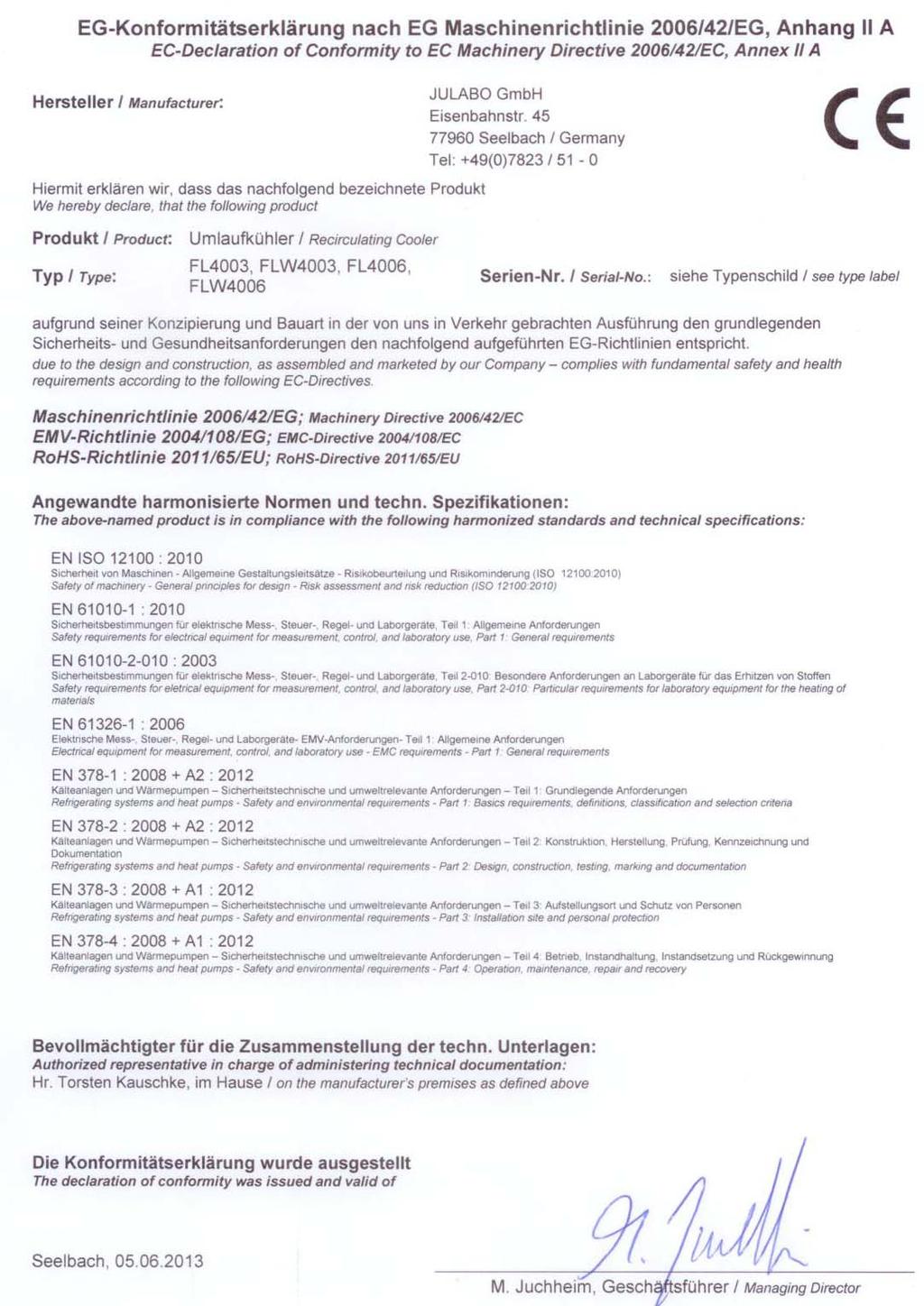
7 2.2. EC Conformity 7
8 8
9 3. Technical specifications Recirculating Cooler FL2503 FLW2503 Cooling air cooled water cooled Working temperature range C Temperature stability C ±0.5 Temperature selection: digital via key pad indication on LED-DISPLAY remote control via personal computer indication on monitor Temperature indication: LED-DISPLAY Resolution C 0.1 Temperature control PID 1 Temperature sensor Pt 100 Excess temperature protection 85 C - fixed value Low liquid level protection float switch Cooling capacity C Medium: Mixture water-glycol kw Cooling compressor 1-stage Refrigerant R404A Electrical connections: Computer interface Alarm output RS232 for external alarm signal Circulating pump: discharge, max. at 0 bar l/min pressure, adjustable at 0 Liter bar Feed pressure indication bar Manometer Manometer Filling level indicator sight glass Filling volume from... to liters Dimensions (WxLxH) cm 60x76x115 Weight kg Ambient temperature range C Return flow temperature C 80 max. Cooling water Flow rate at 20 C inlet temperature l/min IP class according to IEC IP 21 Mains power connection 230 V/50 Hz V/ Hz / / 50 Current draw at 230 V A Mains power connection V/60 Hz V/ Hz / / 60 Current draw at 208V / 220 V A All measurements have been carried out at: rated voltage and frequency, ambient temperature: 20 C 9
10 Recirculating Cooler FL2506 FLW2506 Cooling air cooled water cooled Working temperature range C Temperature stability C ±0.5 Temperature selection: digital via key pad indication on LED-DISPLAY remote control via personal computer indication on monitor Temperature indication: LED-DISPLAY Resolution C 0.1 Temperature control PID 1 Temperature sensor Pt 100 Excess temperature protection 85 C - fixed value Low liquid level protection float switch Cooling capacity C Medium: Mixture water-glycol kw Cooling compressor 1- stage Refrigerant R404A Electrical connections: Computer interface Alarm output RS232 for external alarm signal Circulating pump: discharge, max. at 0 bar l/min pressure, adjustable at 0 Liter bar Feed pressure indication bar Manometer Manometer Filling level indicator sight glass Filling volume from... to liters Dimensions (WxLxH) cm 60x76x115 Weight kg Ambient temperature range C Return flow temperature C 80 max. Cooling water Flow rate at 20 C inlet temperature l/min IP class according to IEC IP 21 Mains power connection 230 V/50 Hz V/ Hz / / 50 Current draw at 230 V A Mains power connection V/60 Hz V/ Hz / / 60 Current draw at 208V / 220 V A All measurements have been carried out at: rated voltage and frequency, ambient temperature: 20 C 10
11 Recirculating Cooler FL4003 FLW4003 Cooling air cooled water cooled Working temperature range C Temperature stability C ±0.5 Temperature selection: digital via key pad indication on LED-DISPLAY remote control via personal computer indication on monitor Temperature indication: LED-DISPLAY Resolution C 0.1 Temperature control PID 1 Temperature sensor Pt 100 Excess temperature protection 85 C - fixed value Low liquid level protection float switch Cooling capacity C Medium: Mixture water-glycol kw Cooling compressor 1- stage Refrigerant R404A Electrical connections: Computer interface Alarm output RS232 for external alarm signal Circulating pump: discharge, max. at 0 bar l/min pressure, adjustable at 0 Liter bar Feed pressure indication bar Manometer Manometer Filling level indicator sight glass Filling volume from... to liters Dimensions (WxLxH) cm 60x76x115 Weight kg Ambient temperature range C Return flow temperature C 80 max. Cooling water Flow rate at 20 C inlet temperature l/min IP class according to IEC IP 21 Mains power connection 400 V/3PNPE/50 Hz V/ Hz /3PNPE/ /3PNPE/50 Current draw at 230 V A 8 8 Mains power connection 230 V/3PPE/60 Hz V/ Hz /3PPE/ /3PPE/60 Current draw at 208V / 220 V A All measurements have been carried out at: rated voltage and frequency, ambient temperature: 20 C 11
12 Recirculating Cooler FL4006 FLW4006 Cooling air cooled water cooled Working temperature range C Temperature stability C ±0.5 Temperature selection: digital via key pad indication on LED-DISPLAY remote control via personal computer indication on monitor Temperature indication: LED-DISPLAY Resolution C 0.1 Temperature control PID 1 Temperature sensor Pt 100 Excess temperature protection 85 C - fixed value Low liquid level protection float switch Cooling capacity C Medium: Mixture water-glycol kw Cooling compressor 1- stage Refrigerant R404A Electrical connections: Computer interface Alarm output RS232 for external alarm signal Circulating pump: discharge, max. at 0 bar l/min pressure, max. at 0 liter bar pressure, adjustable at 0 Liter Feed pressure indication bar Manometer Manometer Filling level indicator sight glass Filling volume from... to liters Dimensions (WxLxH) cm 60x76x115 Weight kg Ambient temperature range C Return flow temperature C 80 max. Cooling water Flow rate at 20 C inlet temperature l/min IP class according to IEC IP 21 Mains power connection 400 V/3PNPE/50 Hz V/ Hz /3PNPE/ /3PNPE/50 Current draw at 230 V A Mains power connection 230 V/3PPE/60 Hz V/ Hz /3PPE/ /3PPE/60 Current draw at 208V / 220 V A All measurements have been carried out at: rated voltage and frequency, ambient temperature: 20 C 12
13 Warning functions and safety installations Excess temperature protection 85 C - fixed value Low liquid level protection float switch Alarm message optical + audible (permanent) Excess temperature - Warning function 75 C Overload protection for compressor and pump motor Classification according to DIN class I Environmental conditions according to IEC : Use only indoor. Altitude up to 2000 m - normal zero. Ambient temperature: C Air humidity: Max. rel. humidity 80 % for temperatures up to +31 C, linear decrease down to 50 % relative humidity at a temperature of +40 C Max. mains fluctuations of ±10 % are permissible. The unit corresponds to Class I Overvoltage category II Pollution degree 2 Caution: The unit is not for use in explosive atmosphere Standards for interference resistance according to EN This unit is an ISM device classified in Group 1 (using high frequency for internal purposes) Class A (industrial and commercial range). 13
14 3.1. Cooling water connection Only for water cooled models - FLW: Cooling water pressure (IN / OUT ) max. 6 bar Difference pressure (IN - OUT ) 2 6 bar Flow rate on FLW250x typical 4,1 l/min Flow rate on FLW400x typical 6,6 l/min Cooling water temperature <20 C Recommended quality of cooling water: ph value 7,5 to 9,0 Sulfate [SO4 2- ] < 100 ppm Hydrocarbonate [HCO3- ] / Sulphate [SO4 2-] > 1 ppm Hardness [Ca2+, Mg2+] / [HCO3-] > 0,5 dh Alkalinity 60 ppm < [HCO3-] < 300 ppm Conductivity < 500 μs / cm Chloride (CL-) < 50 ppm Phosphate (PO43-) < 2 ppm Ammonia (NH3) < 0,5 ppm Free Chlorine < 0,5 ppm Ferri Ions (Fe3+ ) < 0,5 ppm Mangano Ions (Mn2+) < 0,05 ppm Carbon dioxide (CO2) < 10 ppm Hydrosulfide (H2S) < 50 ppm Content of oxygen < 0,1 ppm Algae growth impermissible Suspended solids impermissible Notice: Danger of corrosion of heat exchanger due to unsuitable quality of cooling water. Due to its high content of lime hart water is not suitable for cooling and causes calcination of the heat exchanger. Ferrous water or water containing ferrous particles will cause formation of rust even in heat exchangers made of stainless steel. Chlorous water will cause pitting corrosion in heat exchangers made of stainless steel. Due to its corrosive characteristics distilled and deionized water is unsuitable and will cause corrosion of the bath.. Due to its corrosive characteristics sea water is not suitable. Due to its microbiological (bacteria) components which settle in the heat exchanger untreated and unpurified river water and water from cooling towers is unsuitable. Avoid particulate matter in cooling water. Avoid putrid water. Notice: Cooling water circuit Risk of oil leaking from the cooling circuit (compressor) of the recirculating cooler into the cooling water in case of a fault in the circuit! Observe the laws and regulations of the water distribution company valid in the location where the unit is operated. 14
15 4. Safety notes for the user 4.1. Explanation of safety notes In addition to the safety warnings listed above, warnings are posted throughout the manual. These warnings are designated by an exclamation mark inside an equilateral triangle. Warning of a dangerous situation (Attention! Please follow the documentation). The danger is classified using a signal word. Read and follow these important instructions. Warning: Describes a possibly highly dangerous situation. If these instructions are not followed, serious injury and danger to life could result. Caution: Describes a possibly dangerous situation. If this is not avoided, slight or minor injuries could result. A warning of possible property damage may also be contained in the text. Notice: Describes a possibly harmful situation. If this is not avoided, the product or anything in its surroundings can be damaged Explanation of other notes Note! Draws attention to something special. Important! Indicates usage tips and other useful information Safety instructions Follow the safety recommendations to prevent damage to persons or property. Further, the valid safety instructions for working places must be followed. Only connect the unit to a power socket with earthing contact (PE protective earth)! The power supply plug serves as a safe disconnecting device from the line and must always be easily accessible. Place the instrument on an even surface on a pad made of non-inflammable material. Do not stay in the area below the unit. Make sure you read and understand all instructions and safety precautions listed in this manual before installing or operating your unit. Never operate the unit without bath fluid in the bath. Do not drain the bath fluid while it is hot or cold! Check the temperature of the bath fluid prior to draining (by switching the unit on for a short moment for example). Use suitable connecting tubing. Avoid sharp bends in the tubing, and maintain a sufficient distance from 15
16 surrounding walls. Make sure that the tubing is securely attached. Regularly check the tubing for material defects (e.g., for cracks). Never operate damaged or leaking equipment. Always turn off the unit and disconnect the mains cable from the power source before performing any service or maintenance procedures, or before moving the unit. Always turn off the unit and disconnect the mains cable from the power source before cleaning the unit. Always empty the bath before moving the unit. Transport the unit with care. Sudden jolts or drops may cause damage in the interior of the unit. Observe all warning labels. Never remove warning labels. Never operate equipment with damaged mains power cables. Repairs are to be carried out only by qualified service personnel. Risk of injury for hands. Close cover carefully. Notice: Recommendation in case of single-phase current supply (e.g. FL250x): The safety cutouts of the house wiring should have the trait C (C16A). 16
17 5. Installation Place the unit on an even surface on a base made of nonflammable material. Using the castors (10a, 10b) move the unit to the intended location. For better stability, apply the holding breaks on the front casters (10a). Cooling machine, pump motor and electronics produce intrinsic heat that is dissipated via the venting openings.! Never cover these openings! Keep at least 20 cm of open space on the front and rear venting grids. The place of installation should be large enough and provide sufficient air ventilation to ensure the room does not warm up excessively because of the heat the instrument rejects to the environment. For a fault (leakage) in the refrigeration system, the standard EN 378 prescribes a certain room space to be available for each kg of refrigerant. > For 0.52 kg of refrigerant R-404A, 1 m3 of space is required. Rear view Example: FL2503 Connect the tubings for cooling the external system to the pump connectors M16x1 for feed and return (14) min on the rear of the recirculating cooler. Return - Feed IN OUT Connect a piece of tubing to the overflow connector (15) and drain into a suitable vessel, which always has to be placed lower thant the exit Overflow. Turn the adjusting valve (13) counter-clockwise to set the lowest manometric pressure. Do not set up the unit in the immediate vicinity of heat sources and do not expose to sun light. Before operating the unit after transport, wait about one hour after setting it up. This will allow any oil that has accumulated laterally during transport to flow back down thus ensuring maximum cooling performance of the compressor. OUT Example: PVC-tubing Only water cooled models - FLW: Ensure circulation of cooling water by connecting the tubing to cooling water inlet (IN)and outlet (OUT) on the rear (18) of the recirculating cooler. IN 12 mm inner dia. Cooling water see page 14. Cooling water connectors G3/4" external thread Tubing 12 mm inner dia. tubing IN Cooling water inlet OUT Cooling water outlet 17
18 Even high quality heat exchangers as they are installed in our equipment can be damaged by unsuitable cooling water. The quality of the cooling water depends on the local conditions. The heat exchanger may become leaky due to corrosion or it may become clogged due to particulate matter Caution: Pump pressure Determine and check the max. admissible pressure for the external circuit before putting the unit into operation. The max. pressure is determined by the weakest element in the circuit (e. g. glass equipment). Securely attach all tubing to prevent slipping. Notice: Flood hazard!. In case the system to be cooled is located at a higher level than the recirculating cooler, take note of bath liquid flowing back when the unit is switched off. Return flow safety device Should the filling volume of the bath tank not be sufficient, prevent the liquid from flowing back by using shut-off valves.. Order No. Description Suitable for Shut-off valve G ¾ FL(W) 2503/ Shut-off valve G 1¼ FL(W) 2506/4006 The following questions shall help to recognize possible dangers and to reduce the risks to a minimum. Are all tubes and electrical cables connected and installed? Note: sharp edges, hot surfaces in operation, moving machine parts, etc. What to do when a dangerous substance was spilled on or in the unit? Before starting to work, obtain information concerning the substance and determine the method of decontamination. 18
19 5.1. Tubing Caution: Employ suitable connecting tubing. Make sure that the tubing is securely attached. Avoid sharp bends in the tubing, and maintain a sufficient distance from surrounding walls. Regularly check the tubing for material defects (e.g. for cracks). Preventive maintenance: Replace the tubing from time to time. Recommended tubing: Order No. Description Suitable for m Reinforced tubing ¾ inner dia. ( C) FL(W) 2503/ m Reinforced tubing 1 inner dia. ( C) FL(W) 2506/4006 Tubing insulation m Insulation, 29 mm inner dia. Reinforced tubing ¾ inner dia m Insulation, 35 mm inner dia. Reinforced tubing 1 inner dia. Tube clamps Tube clamps, size 4 Reinforced tubing ¾ inner dia Tube clamps, size 5 Reinforced tubing 1 inner dia. 19
20 Mains RS232 ALARM C C OUT IN 6. Operating controls and functional elements Example: FL25xx Front view Rear view FL IN OUT a 11 10b Draufsicht Push 12 4 Protection lid for fill in opening Push 12 Protection lid for storing place of operating manual 4 Lifting device for transportation by crane 1 ON power switch 20
21 2.0 Keypad, spash-water protected 2.1 Edit keys (set point increase or decrease) 2.2 Enter key Store set point value / parameter 3.0 Indication 3.1 C LED temperature display 3.2 Control indicator Cooling 3.3 Control indicator Alarm 4 Protection lid for fill in opening 5 Feed pressure indication: Manometer 6 Interface RS232: remote control via personal computer RS232 7 Alarm output (for external alarm signal) 8 Filling level indication 9 Drain tap with drain port 10a Castor with brake (at the front) 10b Castor without brake (at the back) 11 Venting grid, removable 12 Protection lid for storing place of operating manual 13 Feed pressure adjusting valve 14 Pump connector OUT pressure pump Pump connector IN Return FL/FLW2503 G ¾ external thread FL/FLW4003 G ¾ external thread FL/FLW2506 G 1¼ FL/FLW4006 G 1¼ 15 Overflow connector 16 Mains circuit breakers (resettable) FL250x 2 Mains circuit breakers (resettable) 4 A (for Electronics) 2 Mains circuit breakers (resettable) 10 A (for Pump motor) F1, F2, F3, F4 16 Mains circuit breakers (resettable) FL400x 1 1 Motor protection switch for compressor motor 0 2 Mains circuit breakers (resettable) 4 A (for Electronics) F1, F2, F3, F4 2 Mains circuit breakers (resettable) 10 A (for Pump motor) 17 Mains power cable with plug 18 OUT IN Only water cooled models IN Cooling water inlet OUT Cooling water outlet G3/4" external thread 12 mm inner dia. tubing 21
22 7. Operating procedures 7.1. Bath fluids Caution: No liability for use of other bath liquids! Please contact JULABO before using other than recommended bath fluids. JULABO takes no responsibility for damages caused by the selection of an unsuitable bath fluid Do not use alcohols. Water: The quality of water depends on local conditions. Due to the high concentration of lime, hard water is not suitable for temperature control because it leads to calcification in the bath. Ferrous water can cause corrosion - even on stainless steel. Chloric water can cause pitting corrosion. Distilled and deionized water is unsuitable. Their special properties cause corrosion in the bath, even in stainless steel. No liablity for use with water. Danger of freezing at working temperatures <5 C. Recommended bath fluids: Bath fluids Temperature range soft/decalcified water 5 C to 80 C See website for list of recommended bath fluids. Contact: see page Power connection Caution: Only connect the unit to a power socket with earthing contact (PE protective earth)! The power supply plug serves as safe disconnecting device from the line and must be always easily accessible. Never operate equipment with damaged mains power cables. Regularly check the mains power cables for material defects (e.g. for cracks). We disclaim all liability for damage caused by incorrect line voltages! Recommendation in case of single-phase current supply (e.g. FL250x): The safety cutouts of the house wiring should have the trait C (C16A). Make sure that the line voltage and frequency match the supply voltage specified on the type plate. 22
23 ON C 7.3. Filling Notice: Risk of injury for hands. Close cover carefully. Top view Take care that no liquid enters the interior of the circulating cooler. Connect the tubing from the external system to the pump connectors and check for leaks Push Push Respect instructions from page 16 to page 19! Check to make sure that the drain tap (9) is closed. Unlock and open lid of fill in opening (4) by slightly pushing. Fill in tempering fluid up to marking H of the filling level indicator. H L Turn the mains switch (1) on (Switching on - see page 23) Switch on unit. To do so press button for approx. 4 seconds. Tempering fluid is pumped into the externally connected system. Refill fluid up to marking H. The recirculating cooler is ready for operation Switching on / Start - Stop Switching on: The recirculating cooler is turned on and off with the mains switch. The unit performs a self-test. All segments of the 4-digit LED temperature DISPLAY and all indicator lights will illuminate (as illustrated on the left). Then the software version and the type of unit is indicated. Examples: (v 1.02) (FL2506) The display "OFF" indicates the unit is ready to operate (standby mode). Start: Press enter for about 4 seconds. The LED temperature DISPLAY indicates the actual bath temperature. Stop: 1. Press enter for about 4 seconds. 2. Wait until the LED display stops blinking! 3. Turn the unit off with the mains power switch. 23
24 7.5. Setting the feed pressure max. Set the max. permissible feed pressure (example: 2 bar) by slowly closing the adjusting valve (13) on the rear and looking at the manometer (5). The max. pressure is determined by the weakest element in the circuit (e. g. glass equipment) Setting the temperatures Factory setting: 25 C Setting can be carried out in the start/stop condition. 1. Press one of the keys for a short moment. The setpoint value instead of the actual value is indicated on the display for about 8 seconds. The value can now be changed. 2. Change value: Press to set a higher value. Press to set a lower value. Keep the keys depressed for the value to change fast. 3. Press enter to store the value AUTOSTART ON / OFF The recirculating cooler has been configured and supplied by JULABO according to N.A.M.U.R. recommendations. This means for the start mode, that the unit must enter a safe operating state after a power failure (non-automatic start mode). This safe operating state is indicated by OFF on the LED temperature display. A complete shutdown of the main functional elements such as compressor and circulating pump is effected simultaneously. Should such a safety standard not be required, the AUTOSTART function (automatic start mode) may be activated, thus allowing the start of the circulator directly by pressing the mains power switch. Keep depressed enter and turn on the unit with the mains power switch. For a short while the LED DISPLAY indicates the effective start mode: AUTOSTART on. AUTOSTART off. Warning: For supervised or unsupervised operation with the AUTOSTART function, avoid any hazardous situation to persons or property. The circulator does no longer conform to N.A.M.U.R. recommendations. 24
25 7.8. Remote control: activate deactivate The recirculating cooler is to be prepared for remote control by a personal computer via the serial interface RS232. Set the interface item from >IOFF< to >ION<. Remote control: activate deactivate: (Interface OFF) Switch off recirculating cooler by pressing the mains switch and wait approx. 5 seconds. (Interface On) Keep depressed the keys and enter simultaneously and turn on the unit with the mains power switch. >I OFF< No remote control via RS232 (Factory setting) >I On< Remote control via RS232 The software version and the type of unit is indicated (see example on the left). The display "roff" indicates the unit is ready to be operated via remote control. 8. Safety installations 8.1. Excess temperature protection + This safety installation is independent of the control circuit. When the temperature of the bath fluid has reached the safety temperature (85 C), a complete shutdown of the compressor and pump is effected. The alarm is indicated by optical and audible signals (continuous tone) and on the LED-DISPLAY appears the error message "Error 14" Low level protection + This safety installation is independent of the control circuit. If the low liquid level protection device is triggered, a complete shutdown of the compressor and circulating pump is effected. The alarm is indicated by optical and audible signals (continuous tone) and on the LED-DISPLAY appears the error message "Error 01". Turn off the unit with the mains switch, refill bath fluid and turn the unit on again! Caution: For refill always use the same bath fluid type that is already in the bath. Notice: Check the low liquid level protection device at least twice a year! To execute a functional test, drain the liquid until the alarm for low liquid level is triggered. Refill liquid afterwards. 25
26 9. Troubleshooting guide / Error messages + Whenever the microprocessor electronics registers a failure, a complete shutdown of the compressor and circulating pump is performed. The alarm light " " illuminates and a continuous signal tone sounds. The LED temperature display indicates the cause for the alarm in form of a code. Press enter to quit the audible signal. The recirculating cooler is operated without bath fluid, or the liquid level is insufficient. Replenish the bath tank with the bath fluid. Tube breakage has occured (insufficient filling level due to excessive bath fluid pumped out). Replace the tubing and replenish the bath tank with the bath fluid. Cable of the working temperature sensor interrupted or short-circuited. Error in A/D converter The return temperature is above the switch-off value of the high temperature protection (85 C). Check dimensioning of application. Use a stronger recirculating cooler if necessary. The motor protection switch for the compressor motor is off. Set motor protection switch to >1<. Check the fuses. The pressure sensor of low pressure side (evaporation pressure) is faulty, short-circuited or has a line interruption. Have the repair done by a specialist. The motor protection switch for the compressor motor is off. Set motor protection switch to >1<. Check the fuses. The pressure sensor of high pressure side is faulty, short-circuited or has a line interruption. Have the repair done by a specialist. The suction gas temperature sensor is faulty, short-circuited or has a line interruption. Have the repair done by a specialist. After eliminating the malfunction, press the mains power switch off and on again to cancel the alarm state. If the unit cannot be returned to operation, contact an authorized service station. 26
27 Warning without a complete shutdown of the unit Excess temperature warning starting at 75 C The return temperature soon reaches the swith-off value of the high temperature protection (85 C). Cooling of the condenser is affected. (see page 32) Clean air-cooled condenser. Check the flow rate and cooling water temperature on water-cooled condenser. If the unit cannot be returned to operation, contact an authorized JULABO service station. Disturbances that are not indicated. Overload protection:: a) for cooling machine b) for pump motor After a short cooling interval, the unit will automatically start running. Mains circuit breakers (resettable) FL250x 2 Mains circuit breakers (resettable) 4 A (for Electronics) 2 Mains circuit breakers (resettable) 10 A (for Pump motor) F1, F2, F3, F4 1 0 F1, F2, F3, F4 Mains circuit breakers (resettable) FL400x 1 Motor protection switch for compressor motor 2 Mains circuit breakers (resettable) 4 A (for Electronics) 2 Mains circuit breakers (resettable) 10 A (for Pump motor) 27
28 10. Electrical connections Notice: Use shielded cables only. The shield of the connecting cable is electrically connected to the plug housing. The unit ensures safe operation if connecting cables with a maximum length of 3 m are used. The use of longer cables does not affect proper performance of the unit, however external interferences may have a negative impact on safe operation. RS232 serial interface This port can be used to connect a computer with an RS232 cable for remote control of the recirculating cooler RS232C Pin assignments RS232: Pin 2 RxD Receive Data Pin 3 TxD Transmit Data Pin 5 0 V Signal GND Pin 7 RTS Request to send Pin 8 CTS Clear to send Pin 1; 4; 6, 9 Reserved - do not use! Accessories: Order No. Description RS232 interface cable 9-pol./9-pol., 2,5 m USB interface adapter cable Alarm output Potential-free change-over contact for external alarm signal. Pin 2 and 3 are connected in case of an alarm. Pin 2 and 1 are connected in normal condition or mains switch "Off". or Switching capacity max. 30 W / 30 VA Switching voltage max. 30 V/ Switching current max. 1 A 28
29 11. Remote control Setup for remote control RS232 Check the interface parameters for both interfaces (on recirculating cooler and PC) and make sure they match. Interface parameters are pre-determined. Type RS232 Baudrate 4800 bauds Parity even Handshake hardware handshake Communication with a PC or a superordinated data system If the recirculating cooler is put into remote control mode the MULTI-DISPLAY (LED) will read R -OFF- = REMOTE STOP. The recirculating cooler is now operated via the computer. In general, the computer (master) sends commands to the recirculating cooler (slave). The recirculating cooler sends data (including error messages) only when the computer sends a query. In remote control mode: After a power interruption the order to start and all values which have to be adjusted must be resent from the personal computer via the interface. AUTOSTART is not possible. A transfer sequence consists of: command out/in command space (; Hex: 20) out/in command parameter (the character separating decimals in a group is the period) out command end of file (; Hex: 0D) out/in command The response (data string) after an in command is always followed by a line feed (LF, Hex: 0A). Important times for a command transmission: To ensure a safe data transfer, the time gap between two commands should be at least 250 ms. The recirculating cooler automatically responds to an in command with a data string followed by a LF (Line Feed). The next command should only be sent after 10 ms. The commands are divided into in or out commands. in commands: asking for parameters to be displayed out commands: setting parameters 29
30 The out commands are valid only in remote control mode. Examples: Command to set the working temperature to15,5 C: out_sp_ Command to ask for the working temperature in_sp_00 Response from the recirculating cooler: 15.5 LF List of commands out commands: Setting parameters or temperature values. Command Parameter Response of recirculating cooler out_mode_05 0 Stop the unit = R OFF-. out_mode_05 1 Start the unit. out_sp_00 xxx.xx Set working temperature in commands: Asking for parameters or temperature values to be displayed. Command Parameter Response of recirculating cooler version none Number of software version (V X.xx) status none Status message, error message (see page 30 ) in_pv_00 none Actual bath temperature. in_sp_00 none Working temperature in_mode_05 none Recirculating cooler in Stop/Start condition: 0 = Stop 1 = Start Status messages Status messages Description 00 MANUAL STOP Recirculating cooler in OFF state. 01 MANUAL START Recirculating cooler in keypad control mode. 02 REMOTE STOP Recirculating cooler in r OFF state. 03 REMOTE START Recirculating cooler in remote control mode. 30
31 11.5. Error messages Error messages Description -01 LOW LEVEL ALARM Low liquid level alarm. -05 WORKING SENSOR ALARM Working temperature sensor short-circuited or interrupted. -03 EXCESS TEMPERATURE WARNING High temperature warning. Starting at 75 C (no deactivation) The return temperature soon reaches the switch-off value of the high temperature warning function (85 C) -07 I 2 C-BUS ERROR Internal error when reading or writing the I 2 C bus. -08 INVALID COMMAND Invalid command. -09 COMMAND NOT ALLOWED IN CURRENT OPERATING MODE Invalid command in current operating mode. -10 VALUE TOO SMALL Entered value too small. -11 VALUE TOO LARGE Entered value too large. -12 TEMPERATURE MEASUREMENT ALARM -14 EXCESS TEMPERATURE PROTECTOR ALARM -20 WARNING: CLEAN CONDENSOR OR CHECK COOLING WATER CIRCUIT OF REFRIGERATOR -51 PRESSURE SENSOR ALARM LOW PRESSURE SIDE Error in A/D converter. The return temperature is above the switch-off value of the high temperature warning function of 85 C. Check dimensioning of application. Use a stronger recirculating cooler if necessary. Cooling of the condenser is affected. Clean air-cooled condenser. Check the flow rate and cooling water temperature on water-cooled condenser. The motor protection switch for the compressor motor is off. Set motor protection switch to >1<. Check the fuses. The pressure sensor of low pressure side (evaporation pressure) is faulty, short-circuited or has a line interruption. Have the repair done by a specialist. -52 PRESSURE SENSOR ALARM HIGH PRESSURE SIDE The motor protection switch for the compressor motor is off. Set motor protection switch to >1<. Check the fuses. The pressure sensor of high pressure side is faulty, short-circuited or has a line interruption. Have the repair done by a specialist. -53 SUCTION GAS TEMPERATURE SENSOR ALARM The suction gas temperature sensor is faulty, shortcircuited or has a line interruption. Have the repair done by a specialist. 31
32 RS232 C ALARM 12. Cleaning / repairing the unit Caution: Always turn off the unit and disconnect the mains cable from the power source before cleaning the unit. Prevent humidity from entering into the circulator. Service and repair work may be performed only by authorized electricians. Notice: Risk of injury for hands when mounting the venting grid. Maintaining the cooling performance Air cooled models = FL To maintain the full cooling performance, clean the condenser from time to time. Switch off the unit, disconnect mains power cable. Hold the venting grid, pull out and remove. Clean the ribbed condenser with a vacuum cleaner. Replace the venting grid. Switch on the unit. OUT Water cooled models = FLW In order to maintain a good condition of the cooling compressor, the sieve in the cooling water input should be cleaned in regular intervals. IN Switch the unit off, disconnect the power plug. Interrupt the cooling water input. Disconnect the tubing from the nozzle IN and take out the dirty sieve. Clean the sieve. Put in the sieve and reconnect the tubing. Open the cooling water input. Take care the tubing connection is not leaking. The unit is ready to operate again. 32
33 Cleaning: Clean the outside of the unit using a wet cloth and low surface tension water. The recirculating cooler is designed for continuous operation under normal conditions. Periodic maintenance is not required. The tank should be filled only with a bath fluid recommended by JULABO. To avoid contamination, it is essential to change the bath fluid from time to time. Repairs: Before asking for a service technician or returning a JULABO instrument for repair, please contact an authorized JULABO service station. When returning the unit: Clean the unit in order to avoid any harm to the service personnel Attach a short fault description. When returning a unit, take care of careful and adequate packing. During transport the unit has to stand upright. Mark the packing correspondingly. JULABO is not responsible for damages that might occur from insufficient packing. JULABO reserves the right to carry out technical modifications with repairs for providing improved performance of a unit. 33


34 12.1. JULABO Service Online remote diagnosis JULABO circulators of the HighTech series are equipped with a black box. This box is implemented in the controller and records all significant data for the last 30 minutes. In case of a failure, this data can be read out from the unit by using special software. This software is available as a free download from \ EasyBlackBox. Installation is easy and is performed step by step. Please observe the instructions. Data read-out is possible in the conditions OFF, R OFF or ALARM. Connect the circulator to the computer using an interface cable. Start the EasyBlackBox program. The program asks for the port used (COM1,...) and the baud rate of the unit. You do not have this information on hand? Simply try it out! The program continues to send the request until the correct settings are made. Data is read out and shown on the monitor divided in the sections >Einstellungen/Settings<, >Alarmspeicher/Alarms stored<, >Blackbox< see example After pressing >Speichern/Save< a text file is compiled. The program proposes a filename - >C:\model description and barcode no.<. Modifications are possible. this file to ServiceUSA@Julabo.com, JULABO's service department. JULABO is thus able to provide rapid support. 34
35 C C RS232 ALARM RS232 ALARM Draining Notice: Store and dispose the used bath fluid according to the laws for environmental protection. Risk of injury for hands when mounting the venting grid. Turn off the unit and disconnect the mains cable from the power source. Hold the venting grid, pull out and remove. Slide a short piece of tube onto the drain port and hold it into a pail. Open the drain tap and empty the unit completely. Close the drain tap and replace the venting grid. 13. Adequate storing of operating manual Store the operating manual at the foreseen place at the unit and lock it by means of the protection lid (18). 35
36 14. Warranty conditions JULABO GmbH warrants its products against defects in material or in workmanship, when used under appropriate conditions and in accordance with appropriate operating instructions for a period of ONE YEAR. Extension of the warranty period free of charge With the 1PLUS warranty the user receives a free of charge extension to the warranty of up to 24 months, limited to a maximum of working hours. To apply for this extended warranty the user must register the unit on the JULABO web site indicating the serial no. The extended warranty will apply from the date of JULABO GmbH s original invoice. JULABO GmbH reserves the right to decide the validity of any warranty claim. In case of faults arising either due to faulty materials or workmanship, parts will be repaired or replaced free of charge, or a new replacement unit will be supplied. Any other compensation claims are excluded from this guarantee. 36
Operating manual. Recirculating Coolers FL300 FL601. English V2.doc FL300
 Operating manual Recirculating Coolers FL300 FL601 FL300 RS232 ALARM English 19514818-V2.doc 08.10.13 Congratulations! You have made an excellent choice. JULABO thanks you for the trust you have placed
Operating manual. Recirculating Coolers FLW1703 FL1203. English
 English Operating manual Recirculating Coolers FL1201 FL1203 FL1203 RS232 ALARM FL1701 FL1703 FLW1701 FLW1703 1.951.4822-V2 10/13 Druck: 08.10.2013 JULABO GmbH 77960 Seelbach / Germany Tel. +49 (0) 7823
Operating manual. Recirculating Coolers FL11006 FLW English. Innovative Temperature Technology
 RS232 C ALARM English Operating manual Recirculating Coolers FL7006 FLW7006 FL7006 FL11006 FLW11006 Innovative Temperature Technology Changes without prior notification reserved Printed in Germany 1.951.4828
Operating manual. Recirculating Coolers. English
 RS232 ALARM C English Operating manual Recirculating Coolers FL2503 FL2506 FL4003 FL4006 FLW2503 FLW2506 FLW4003 FLW4006 FL2506 1.951.4829-V6 07/17 19514829-V6.docx Print date: 20.07.2017 Congratulations!
Operating Manual. Recirculating Cooler. Original Operating Manual
 Operating Manual Recirculating Cooler F250 F500 Original Operating Manual 1.951.4806-V0 12/12 Proj. 1789 JULABO GmbH 77960 Seelbach / Germany Tel. +49 (0) 7823 / 51-0 Fax +49 (0) 7823 / 24 91 info@julabo.de
Operating manual. English. Heating Immersion Circulator
 English Operating manual Heating Immersion Circulator Innovative Temperature Technology 1.951.0232BE0 11/06 JULABO Labortechnik GmbH 77960 Seelbach / Germany +49 (0) 7823 / 51-0 +49 (0) 7823 / 24 91 info@julabo.de
English. Operating manual F32-EH F33-EH F34-EH. Refrigerated and Heating Circulators
 English Operating manual Refrigerated and Heating Circulators F12-EH F25-EH F32-EH F33-EH F34-EH 1.951.0253-V2 06/13 JULABO GmbH 77960 Seelbach / Germany Tel. +49 (0) 7823 / 51-0 Fax +49 (0) 7823 / 24
Operating manual. Recirculating Coolers FL300 FL601. English _a.doc FL300
 Operating manual Recirculating Coolers FL300 FL601 FL300 RS232 ALARM English 19534818_a.doc 02.05.11 Congratulations! You have made an excellent choice. JULABO thanks you for the trust you have placed
Operating manual. Recirculating Coolers FL20006 FLW English
 English Operating manual Recirculating Coolers FL20006 FLW20006 JULABO USA, Inc. 884 Marcon Boulevard Allentown, PA 18109 Phone: +1(610) 231-0250 Fax: +1(610) 231-0260 info @ julabo.com www.julabo.com
Operating manual. Recirculating Coolers FLW1703 FL1203. English
 English Operating manual Recirculating Coolers FL1201 FL1203 FL1203 RS232 ALARM FL1701 FL1703 FLW1701 FLW1703 JULABO USA, Inc. 884 Marcon Boulevard Allentown, PA 18109 Phone: +1(610) 231-0250 Fax: +1(610)
Refrigerated Circulators F12-MP / F25-MP / F26-MP
 ! Refrigerated Circulators F12-MP / F25-MP / F26-MP! 1a 1.951.0722BE4 01/03 19510722.DOC Congratulations! You have made an excellent choice. JULABO thanks you for the trust you have placed in us. This
Operating Manual. English. Refrigerators for chemicals KRC 50 KRC 180
 English Operating Manual Refrigerators for chemicals KRC 50 KRC 180 1.951.6610-V1 12/12 JULABO GmbH 77960 Seelbach / Germany Tel. +49 (0) 7823 / 51-0 Fax +49 (0) 7823 / 24 91 info@julabo.de www.julabo.de
Operating manual. English. Cryo-Compact Circulators. The Economy-Series
 English Operating manual Cryo-Compact Circulators The Economy-Series CF30 CF40 JULABO USA, Inc. 884 Marcon Boulevard Allentown, PA 18109 Phone: +1(610) 231-0250 Fax: +1(610) 231-0260 info @ julabo.com
Circulators MV-4/ MV-6/ MV-12/ MV-26 MW-4/ MW-6/ MW-12/ MW-26 MW-Z
 Circulators MV-4/ MV-6/ MV-12/ MV-26 MW-4/ MW-6/ MW-12/ MW-26 MW-Z! 1.951.1402BE2 01/03 19511402.doc Operating controls and functional elements Congratulations! You have made an excellent choice. JULABO
R -OFF- 11. Remote control Setup for remote control. S xxxx I xxxx
 11. Remote control 11.1. Setup for remote control SERIAL R -OFF- S xxxx I xxxx 1. Check the interface parameters for both interfaces (on circulator and PC) and make sure they match. (Serial interface see
Operating Manual. Refrigerated and Heating Circulators. English F12-MA FP35-MA F25-MA FP40-MA F33-MA FP50-MA F32-MA F34-MA FPW50-MA
 English Operating Manual Refrigerated and Heating Circulators F12-MA FP35-MA F25-MA FP40-MA F33-MA FP50-MA F32-MA F34-MA FPW50-MA Original Operating Manual 1.951.0366-V2 05/14 JULABO GmbH 77960 Seelbach
Operating Manual. Refrigerated and Heating Circulators. English F12-MA FP35-MA F25-MA FP40-MA F33-MA FP50-MA F32-MA F34-MA FPW50-MA
 English Operating Manual Refrigerated and Heating Circulators F12-MA FP35-MA F25-MA FP40-MA F33-MA FP50-MA F32-MA F34-MA FPW50-MA Original Operating Manual 1.951.0366 10/12 JULABO Labortechnik GmbH 77960
Operating Manual. Recirculating Cooler F250 F500 F1000
 Operating Manual Recirculating Cooler F250 F500 F1000 Original Operating Manual Proj. 1789 JULABO USA, Inc. 884 Marcon Boulevard Allentown, PA 18109 Phone: +1(610) 231-0250 Fax: +1(610) 231-0260 info @
Operating Manual. SemiChill Recirculating Coolers. Eco-Serie. SC 5000a air cooled. SC 5000w water cooled. SC 10000w water cooled
 Flow Cond. C 60 30 10 C 130 180 220 A US T- O N E NERGENCY S TOP OFF ON Operating Manual SemiChill Recirculating Coolers Eco-Serie ES SC 5000a air cooled SC 10000 SC 5000w water cooled SC 10000w water
Operating manual. English. Water Baths TW2 TW8 TW12 TW20
 English Operating manual Water Baths TW2 TW8 TW12 TW20 C JULABO USA, Inc. 884 Marcon Boulevard Allentown, PA 18109 Phone: +1(610) 231-0250 Fax: +1(610) 231-0260 info @ julabo.com www.julabo.com 19536062_a.doc
Operating manual. English. Shaking Water Baths SW22 SW23
 English Operating manual Shaking Water Baths SW22 SW23 1.951.4023-V1 05/13 JULABO GmbH 77960 Seelbach / Germany Tel. +49 (0) 7823 / 51-0 Fax +49 (0) 7823 / 24 91 info@julabo.de www.julabo.de 19514023-V1.doc
Operating Manual. Refrigerated and Heating Circulators. English F12-MA FP35-MA F25-MA FP40-MA F33-MA FP50-MA F32-MA F34-MA FPW50-MA
 English Operating Manual Refrigerated and Heating Circulators F12-MA FP35-MA F25-MA FP40-MA F33-MA FP50-MA F32-MA F34-MA FPW50-MA Original Operating Manual JULABO USA, Inc. 884 Marcon Boulevard Allentown,
Operating manual. English
 English Operating manual Open Heating Bath Circulators MB-13A / MB-19A MB-13 / MB-17 / MB-19 Heating Circulators with Open Bath MB-5A / MB-7A / MB-5M MB-5 1.951.0306 01/11 JULABO Labortechnik GmbH 77960
Operating Manual. Refrigerated and Heating Circulators F25-ME F26-ME F32-ME F33-ME F34-ME FP40-ME FP50-ME. English. water-cooled FPW50-ME
 English Operating Manual ME Refrigerated and Heating Circulators F25-ME F26-ME F32-ME F33-ME F34-ME FP40-ME FP50-ME water-cooled FPW50-ME Translation of the Original Operating Manual 19530512-V1.doc 14.03.16
Artisan Technology Group is your source for quality new and certified-used/pre-owned equipment
 Artisan Technology Group is your source for quality new and certified-used/pre-owned equipment FAST SHIPPING AND DELIVERY TENS OF THOUSANDS OF IN-STOCK ITEMS EQUIPMENT DEMOS HUNDREDS OF MANUFACTURERS SUPPORTED
Operating Manual. Refrigerated and Heating Circulators. air cooled F25-HE F32-HE F34-HE FP40-HE FP50-HE FPW50-HE. English.
 English Operating Manual Refrigerated and Heating Circulators air cooled F25- F32- F34- FP40- FP50- water cooled FPW50- Original Operating Manual 1.951.2460-V6 06/18 JULABO GmbH 77960 Seelbach / Germany
Operating Manual. Ultra-Low Refrigerated Circulators. English. air-cooled FP52-SL FP55-SL FP90-SL. water-cooled FPW52-SL FPW55-SL FPW90-SL FPW91-SL
 English Operating Manual Ultra-Low Refrigerated Circulators air-cooled FP52-SL FP55-SL FP90-SL water-cooled FPW52-SL FPW55-SL FPW90-SL FPW91-SL upgradable with supplementary pump - HSP upgradable with
Operating Manual. High Dynamic Temperature System with integrated programmer LH 46 LH85
 Operating Manual High Dynamic Temperature System with integrated programmer LH 46 LH85 1.951.2785-V1 12/12 JULABO GmbH 77960 Seelbach / Germany Tel. +49 (0) 7823 / 51-0 Fax +49 (0) 7823 / 24 91 info@julabo.de
Operating Manual. Refrigerated/Heating Circulators F25-HL F32-HL F33-HL FP35-HL FP40-HL FP45-HL FP50-HL FPW50-HL. English. air-cooled.
 English Operating Manual Refrigerated/Heating Circulators air-cooled F25-HL F32-HL F33-HL FP35-HL FP40-HL FP45-HL FP50-HL water-cooled FPW50-HL Original Operating Manual JULABO USA, Inc. 884 Marcon Boulevard
Operating Manual. Ultra-Low Refrigerated Circulators. English. air-cooled FP52-SL FP55-SL FP90-SL. water-cooled FPW52-SL FPW55-SL FPW90-SL FPW91-SL
 English Operating Manual Ultra-Low Refrigerated Circulators air-cooled FP52- FP55- FP90- water-cooled FPW52- FPW55- FPW90- FPW91- upgradable with supplementary pump - HSP upgradable with supplementary
Operating Manual. Visco-Baths ME-31A ME-16G ME-18V. English
 English Operating Manual Visco-Baths -31A -16G -18V -18V 1.951.0504-V3 03/16 JULABO GmbH 77960 Seelbach / Germany Tel. +49 (0) 7823 / 51-0 Fax +49 (0) 7823 / 24 91 info.de@julabo.com www.julabo.com 19510504-V3.doc
AIRGOCLEAN 10 E OPERATING MANUAL AIR CLEANER TRT-BA-AIRGOCLEAN10E-TC-001-EN
 AIRGOCLEAN 10 E EN OPERATING MANUAL AIR CLEANER TRT-BA-AIRGOCLEAN10E-TC-001-EN Table of contents Notes regarding the operating manual... 1 You can download the current version of the operating manual and
OPERATING MANUAL English Chemical Resistant Diaphragm Pump
 OPERATING MANUAL English Chemical Resistant Diaphragm Pump C300 / C400/ C410 / C510/ C600 / C610 Room 303, Hall C, Office Building M8, No. 1 Jiuxianqiao East Road, Chaoyang District, Beijing 100015, China
Operating instructions Page 12
 Operating instructions Page 12 Refrigerator with explosion-proof interior container Read the operating instructions before switching on for the first time 7082 271-00 LKEXv 910 Disposal notes The appliance
SHAKING WATER BATHS ENGLISH
 SHAKING WATER BATHS ENGLISH Display Technical Features Operation Easy to read Large LED temperature display for actual value and setpoint (display resolution 0.1 C) Several values at a glance Large Multi-Display
TIH 300 S / TIH 400 S / TIH 500 S / TIH 700 S / TIH 900 S / TIH 1100 S
 TIH 300 S / TIH 400 S / TIH 500 S / TIH 700 S / TIH 900 S / TIH 1100 S EN OPERATING MANUAL INFRARED HEATING PANEL TRT-BA-TIH300S-TIH400S-TIH500S-TIH700S-TIH900S-TIH1100S-TC-002-EN Table of contents Notes
Recirculating Coolers
 09 Recirculating Coolers (chillers) General Recirculating Coolers Low Temp. Recirculating Coolers Advanced Low Temp. Recirculating Coolers High Temp. Recirculating Coolers Compact Recirculating Cooler
Installation, Operation and Maintenance Manual
 Installation, Operation and Maintenance Manual Packaged Chiller Models CC 6601, 6501, 6401, 6301, 6201, 6101 For Service, please contact Pfannenberg Service Company: U.S.A. Pfannenberg Inc. 68 Ward Road.
Operator s Manual. Histology Bath
 Operator s Manual Histology Bath 110-827 05.09.12 Table of Contents Introduction... 2 General Safety Information... 2 Safety Recommendations... 3 Unpacking Your Histology Bath...4 Contents...4 Components
Refrigerated Incubator Model and Operating Instructions
 Refrigerated Incubator Model 165000 and 165000-2 Operating Instructions N2400379 - Rev. 1 08May2018 1 Contents 1. SAFETY...3 1.1. EMF INTERFERENCE...4 1. PRODUCT INFORMATION...5 1.1 INTRODUCTION...5 2.
Installation and Operating Instructions DÜRR Regeneration Unit for X-ray developers XR 24, XR24 II, XR 24 Nova, XR 24 Pro
 Installation and Operating Instructions DÜRR Regeneration Unit for X-ray developers XR 24, XR24 II, XR 24 Nova, XR 24 Pro 2006/01 Content Important Information 1. Notes... 3 1.1 CE - Labeling... 3 1.2
Operating instructions Page 14. Refrigerator Read the operating instructions before switching on for the first time
 Operating instructions Page 14 Refrigerator Read the operating instructions before switching on for the first time 7085 039-00 LKv 5710 Content Disposal notes... 14 Description of the appliance... 14 Safety
NON-CYCLING REFRIGERATED AIR/GAS DRYERS QPNC 75 to QPNC 250 OPERATOR S MANUAL
 NON-CYCLING REFRIGERATED AIR/GAS DRYERS QPNC 75 to QPNC 250 OPERATOR S MANUAL DATE OF PURCHASE: MODEL: SERIAL NO.: Record above information from nameplate. Retain this information for future reference.
Series Temperature Controller Instruction Sheet
 Series Temperature Controller Instruction Sheet Thank you very much for purchasing DELTA A Series. Please read this instruction sheet before using your A series to ensure proper operation and please keep
Operator s Manual. IP-100 Immersion Probe Cooler
 Operator s Manual IP-100 Immersion Probe Cooler 110-810 04.27.11 Table of Contents Introduction... 3 General Information... 3 General Safety Information... 3 Safety Recommendations... 4 Unpacking Your
User Manual GV25 GV35 GV702. Company information: Original instructions GV12066 (1)
") User Manual Original instructions GV25 GV35 GV702 Company information: www.vipercleaning.eu info-eu@vipercleaning.com GV12066 (1) 2012-04-10 USER MANUAL ENGLISH TABLE OF CONTENTS Introduction... 4 Manual
User Manual Original instructions GV25 GV35 GV702 Company information: www.vipercleaning.eu info-eu@vipercleaning.com GV12066 (1) 2012-04-10 USER MANUAL ENGLISH TABLE OF CONTENTS Introduction... 4 Manual
TTK 75 ECO OPERATING MANUAL DEHUMIDIFIER TRT-BA-TTK75ECO-TC-002-EN
 TTK 75 ECO EN OPERATING MANUAL DEHUMIDIFIER TRT-BA-TTK75ECO-TC-002-EN Table of contents Notes regarding the operating manual... 01 Information about the device... 02 Safety... 04 Transport...05 Start-up...05
Part 3 Troubleshooting
 Part Troubleshooting What is in this part? This part contains the following chapters: Chapter See page Troubleshooting 2 Error Codes: Hydro-box 7 Error Codes: Outdoor Units Error Codes: System Malfunctions
Digital 7 Square Plate Magnetic Stirrer
 Digital 7 Square (Hotplate) Magnetic Stirrer User Manual MS7-Pro Digital 7 Square Plate Magnetic Stirrer MS7-H550-Pro Digital 7 Square Hotplate Magnetic Stirrer Please read the User Manual carefully before
testo Leakage detector for refrigerants Bedienungsanleitung Instruction manual
 testo 316-4 Leakage detector for refrigerants Bedienungsanleitung Instruction manual de en 12 Safety and environment Safety and environment On this document Read this document through carefully, and familiarize
Operating instructions
 The right temperature worldwide Operating instructions Microcool MC 250, MC 350, MC 600, MC 1200, MC 1200 W Circulation chiller Read the operating manual before starting all work. LAUDA DR. R. WOBSER GMBH
K Operating Instructions. Before first use of the unit read these operating instructions and act in accordance with them.
 K 1.100 Operating Instructions Before first use of the unit read these operating instructions and act in accordance with them. www.kaercher.com/register-and-win 59651430 (10/13) Contents General information..............
Operating instructions Page 14
 Operating instructions Page 14 Refrigerator with explosion-proof interior container Read the operating instructions before switching on for the first time 7085 479-00 LKexv Inhalt Disposal notes... 14
Operating instructions Page 14. Refrigerator Read the operating instructions before switching on for the first time
 Operating instructions Page 14 Refrigerator Read the operating instructions before switching on for the first time 7085 473-00 MKv Content Disposal notes... 14 Description of the appliance... 14 Safety
TTV 1500 / TTV 3000 OPERATING MANUAL CONVEYING FAN TRT-BA-TTV TC EN
 TTV 1500 / TTV 3000 EN OPERATING MANUAL CONVEYING FAN TRT-BA-TTV1500-3000-TC2016-26-004-EN Table of contents Notes regarding the operating manual... 2 You can download the current version of the operating
USER MANUAL FOR OPERATING SYSTEM
 P2262 ALARM PANEL USER MANUAL FOR OPERATING SYSTEM 21765-07 September 1999 Associated Controls (Aust) PTY. LTD. 29 Smith Street, Hillsdale, NSW, 2036. PH (02) 9311 3255, FAX (02) 9311 3779 Page 1 of 177
Residential Gas Condensing Boiler Greenstar ZBR16/21/28/35/42-3A... ZWB28/35/42-3A...
 70 80 99-00-O Residential Gas Condensing Boiler ZBR//8/35/4-3A... ZWB8/35/4-3A... 70 80 993 (03/03) CA/US Operating Instructions Contents Contents Key to symbols and safety instructions............................
APC BC300 Series 40kW 208/450/480V User Guide
 APC BC300 Series 40kW 208/450/480V User Guide Copyright 2002 APC Denmark ApS This manual is subject to change without notice and does not represent a commitment on the part of the vendor Thank You Thank
Millo / Millo pro. Nr x000 / 1805-x000. Ideen für die Dentaltechnik A
 Millo / Millo pro Nr. 1804-x000 / 1805-x000 0609 21-6543 A Ideen für die Dentaltechnik 1 2 3 4 5 6 7 8 9 10 11 12 Millo / Millo pro No. 1804-x000 / 1805-x000 ENGLISH Content Introduction... 15 Symbols...
MS-H-Pro-T Magnetic Hotplate-Stirrer with Timer
 MS-H-Pro-T Magnetic Hotplate-Stirrer with Timer User Manual MS-H-Pro T Magnetic Hotplate-Stirrer with Timer Please read the User Manual carefully before use, and follow all operating and safety instructions!
Warning: 230V / 1ph / 50Hz V / 3ph / 50Hz. Remarks: Make sure that you have enough power. (See page 15 Cable table)
") 1 2 Warning: - Do not place your hand or any other objects into the air outlet and fan. It could damage the heat pump and cause injuries; - In case of any abnormality with the heat pump, cut off the power
1 2 Warning: - Do not place your hand or any other objects into the air outlet and fan. It could damage the heat pump and cause injuries; - In case of any abnormality with the heat pump, cut off the power
smardy - pure water Reverse osmosis system YR100-A 75 GPD
 smardy - pure water Reverse osmosis system YR100-A 75 GPD Instruction manual [EN] Please read this manual carefully before operating the device and subsequently keep the instruction manual safely and within
E21.X.01.6C-05 Operating Manual EB2000 MC page 1. Operating manual EB2000 MC. for up to 9 sensor modules. Version 3.0
 E21.X.01.6C-05 Operating Manual EB2000 MC page 1 Operating manual EB2000 MC EASYBUS-display with MIN-/MAX-alarm for up to 9 sensor modules Version 3.0 Pursuant to EN 50 081-1 and EN 50 082-2 for unlimited
Model No.: PS08-01 PS10-01 Ref: KY80 KY100
 8,000/10,000/12,000 BTU Portable Air Conditioner Operating Instructions Model No.: PS08-01 PS10-01 Ref: KY80 KY100 Model No.: PS12-03 Ref: KY120 3119233 V160310 Thank you for choosing a Soleus Air Portable
testo Leakage detector for gas Instruction manual
 testo 316-2 Leakage detector for gas Instruction manual 2 Safety and environment Safety and environment On this document > Read this document through carefully, and familiarize yourself with the product
G-10s. Instruction Manual. G-Series Cooler UPRIGHT COOLER. Part No.11IPA
 G-Series Cooler UPRIGHT COOLER Part No.11IPA-062800 Instruction Manual FOR YOUR FUTURE REFERENCE Thank you for using our product. This manual will guide you in getting the best use of your cooler. Remember
User instructions DHP-AT
 User instructions DHP-AT VUGFC202 If these instructions are not followed during installation and service, Danfoss A/S liability according to the applicable warranty is not binding. Danfoss A/S retains
GF-3000 Ground Fog Machine. user manual
 GF-3000 Ground Fog Machine user manual Musikhaus Thomann Thomann GmbH Hans-Thomann-Straße 1 96138 Burgebrach Germany Telephone: +49 (0) 9546 9223-0 E-mail: info@thomann.de Internet: www.thomann.de 19.08.2015,
Digital Heat Block User Manual
 Digital Heat Block User Manual Quidel Digital Heat Block Page 1 of 10 General Information Quidel Contact Information Contact Quidel Technical Support from 8:00 a.m. to 5:00 p.m. EST Tel: 800.874.1517 (in
OWNER S MANUAL FOR AIR ADMIRAL VACUUM/PRESSURE STATION MODELS:
 OWNER S MANUAL FOR AIR ADMIRAL VACUUM/PRESSURE STATION MODELS: 79202-00 79202-05 79202-30 79202-35 Approval Agency s Model 79202-00 & 79202-05 Model 79202-30 & 79202-35 Not recommended for pumping acid,
Installation instructions and operating manual. Sauna control system FCU1000 / FCU1200
 Series FCU1x00 Installation instructions and operating manual Sauna control system FCU1000 / FCU1200 only sauna FCU1000 additional humidity FCU1200 Doc-ID: B_M_FCU1xxx-A5_EN Version: V 1.06 certificated
USERS MANUAL FOR GAS BOILERS
 USERS MANUAL FOR GAS BOILERS PLEASE READ THE MANUAL CAREFULLY: IT CONTAINS IMPORTANT INFORMATION REGARDING SAFETY, INSTALLATION, USE AND MAINTENANCE OF THE APPLIANCE MODELS: NOVADENS 24 NOVADENS 24C NOVADENS
CHESNEY S. Bio-Ethanol Installation & User Manual. model: EFB1200. Issue 01
 CHESNEY S Bio-Ethanol Installation & User Manual model: EFB1200 Issue 01 1 2 Thank you for choosing this Chesney s Bio-Ethanol fire. Please read this information guide carefully in order to safely install,
EN - english. Instructions for installation and operation. Mobile humidity meter DP 207
 EN - english Instructions for installation and operation Mobile humidity meter DP 207 Dear customers, Thank you very much for deciding in favour of the mobile humidity measuring instrument DP 207. Please
Operation Manual Airbrush Compressor AH28A ARTICLE 34247
 Operation Manual Airbrush Compressor AH28A ARTICLE 34247 Read and follow the operating instructions and safety information before using for the first time. Technical changes reserved! Due to further developments,
Tel.: 016/ Fax: 016/
 4The HAAKE C/DC Circulator Range Inexpensive circulators with a high power capacity The HAAKE C/DC circulators are inexpensive units with a high power capacity. These circulators are small, slimline units
Operating instructions Page 14. Refrigerator Read the operating instructions before switching on for the first time
 Operating instructions Page 14 Refrigerator Read the operating instructions before switching on for the first time 7084 309-00 LKUv Disposal notes The appliance contains reusable materials and should be
Sierra Model 951 Digital Flo-Box. Instruction Manual Part Number IM-951 Revision A 09-05
 Sierra Model 951 Digital Flo-Box Instruction Manual Part Number IM-951 Revision A 09-05 5 Harris Court, Building L Monterey, CA 93940 (831) 373-0200 (800) 866-0200 Fax (831) 373-4402 www.sierrainstruments.com
Vacuum Controller with Control Unit VC 900
 Operating Instructions Read and observe these operating instructions! Vacuum Controller with Control Unit VC 900 KNF Neuberger GmbH Alter Weg 3 79112 Freiburg Germany Tel. +49 (0)7664 / 5909-0 Fax +49
Cabinet Refrigerators/Freezers Instruction manual
 Cabinet Refrigerators/Freezers Instruction manual Model DL893-A/DL894-A/DL895-A/DL896-A/DL897-A/DL898-A/DL899-A /CK480-A Safety Tips Position on a flat, stable surface. A service agent/qualified technician
User Manual. MS7-H550-Pro MS7-H550-S MS7-Pro MS7-S
 User Manual MS7-H550-Pro MS7-H550-S MS7-Pro MS7-S LCD Digital 7 Square Hotplate Magnetic Stirrer LED Digital 7 Square Hotplate Magnetic Stirrer LCD Digital 7 Square Plate Magnetic Stirrer Classic 7 Square
OPTISENS TUR 2000 Technical Datasheet
 OPTISENS TUR 2000 Technical Datasheet Sensor for turbidity measurement in water and wastewater Rugged design for harsh applications Integrated transmitter with direct 4...20 ma output Near infrared light
ELECTRIC BOILERS FOR CENTRAL HEATING
 ELECTRIC BOILERS FOR CENTRAL HEATING TermoMax INSTRUCTIONS FOR INSTALLATION INSTRUCTIONS FOR INSTALLATION We reserve the right of alternations WE ARE NOT LIABLE FOR DAMAGES RESULTING FROM NON- OBSERVING
MODEL 7000 SUCTION UNIT
 MODEL 7000 SUCTION UNIT OPERATOR S MANUAL Caution Federal law restricts this device to sale by or on order of a physician, or any other practitioner licensed by the law of the State in which he practices
SELF-PRIMING JET PUMPS
 SS Anti-Rust SS Shaft Copper & Cold-rolled SELF-PRIMING JET PUMPS CONTENTS 1. Applications.... Model Description.... Technical Data... 4. Implementation Standards... 5. Safety Precautions... 6. Product
CHESNEY S. Bio-Ethanol Installation & User Manual. model: EFB1200 with resevoir. Issue 01
 CHESNEY S Bio-Ethanol Installation & User Manual model: EFB1200 with resevoir Issue 01 1 2 Thank you for choosing this Chesney s Bio-Ethanol fire. Please read this information guide carefully in order
Bedienungsanleitung. Ideas for dental technology. Made in Germany C
 Bedienungsanleitung 216604 C 01022013 Made in Germany Ideas for dental technology GLISH Instruction manual 1. Introduction...1 1.1 Employed Symbols...1 2. Safety...2 2.1 Intended use...2 2.2 Improper use...2
Dear Valued Customer:
 Dear Valued Customer: Thank you for purchasing CARON Products & Services equipment. We appreciate your business and look forward to being your preferred supplier of controlled environment equipment products
Decentralised ventilation units
 Notes on installation Decentralised ventilation units FSL / SCHOOLAIR GB/en TROX GmbH Heinrich-Trox-Platz 47504 Neukirchen-Vluyn Germany Phone: +49 (0) 2845 2020 Fax: +49 (0) 2845 202265 E-mail: trox@trox.de
RCM-77. Instruction Manual. G-Series Cooler. U.S. Patent No. 8,215,125 RECHARGE COLD MERCHANDISER
 G-Series Cooler RECHARGE COLD MERCHANDISER U.S. Patent No. 8,215,125 Instruction Manual FOR YOUR FUTURE REFERENCE This easy-to-use manual will guide you in getting the best use of your cooler. Remember
Instruction manual ROTACOOL
 Instruction manual ROTACOOL 2 Key Page 2 1 Cover 2 Cooling liquid connection 3 Right threaded socket 4 Left threaded socket Page 3 5 Cup 6 Display 7 Cooling LED 8 Pump LED 9 On/Off button 10 Main switch
RCM-77. Instruction Manual. G-Series Cooler. Manual is for the following model: RCM-77-N23EB. U.S. Patent No. 8,215,125 RECHARGEABLE COLD MERCHANDISER
 G-Series Cooler RCM-77 RECHARGEABLE COLD MERCHANDISER Manual is for the following model: RCM-77-N23EB U.S. Patent No. 8,215,125 Instruction Manual Manual is for the following model: RCM-77-N23EB Instruction
Silent TS. Nr / Ideas for dental technology / A. Made in Germany
 Silent TS Nr. 2921-0050 / 2921-1050 21-9191 30102012 / A Made in Germany Ideas for dental technology 1 2 3 4 5 6 7 8 9 10 11 12 13 14 15 16 17 18 19 20 21 22 23 24 25 26 27 28 29 30 31 Silent TS Nr. 2921-0050
OWNER S MANUAL DLFCAB / DLFCHB / DLFDAB / DLFDHB High Wall Ductless System Sizes 09 36
 OWNER S MANUAL DLFCAB / DLFCHB / DLFDAB / DLFDHB High Wall Ductless System Sizes 09 36 TABLE OF CONTENTS PAGE SAFETY PRECAUTIONS... 2 GENERAL... 2 INDOOR UNIT PART NAMES... 3 REMOTE CONTROL PART NAMES...
IMR IX176 Portable Gas Detector User Manual
 IMR Portable Gas Detector User Manual Read this manual carefully before using this device. (727) 328-2818 / (800) RING-IMR Fax: (727) 328-2826 www.imrusa.com Ver. 1.0A4 CONTENTS SERVICE GUIDELINES... 3
Model MKFT 115 Dynamic climate chambers for rapid temperature changes with humidity control and extended low temperature range
 Model MKFT 115 Dynamic climate chambers for rapid temperature changes with humidity control and extended low temperature range The BINDER MKFT series environmental simulation chamber for low temperature
Instruction Manual. For All Corning Hot Plates, Stirrers, Stirrer/Hot Plates with Digital Displays, and External Temperature Controller (6795PR)
") Instruction Manual For All Corning Hot Plates, Stirrers, Stirrer/Hot Plates with Digital Displays, and External Temperature Controller (6795PR) Corning Cat. No. 230V 230V Model No. Product Top Plate Size
Instruction Manual For All Corning Hot Plates, Stirrers, Stirrer/Hot Plates with Digital Displays, and External Temperature Controller (6795PR) Corning Cat. No. 230V 230V Model No. Product Top Plate Size
Read these instructions before using and keep them available at all times!
 Rimi 700220 V3/0214 GB/UK ENGLISH Translation of the original instruction manual Read these instructions before using and keep them available at all times! 1. General information... 18 1.1 Information
Owner's Manual TABLE OF CONTENTS
 40MAQ High Wall Ductless System Sizes 09 to 36 Owner's Manual TABLE OF CONTENTS PAGE A NOTE ABOUT SAFETY... 2 GENERAL... 2 PART NAMES... 3 FUNCTION BUTTONS... 4 DISPLAY PANELS... 5 REMOTE CONTROL... 6
SILENT compact /
 SILT compact 2934 0000 / 2934 1000 TRANSLATION OF THE ORIGINAL INSTRUCTIONS FOR USE Made in Germany Ideas for dental technology 21-2245 21052015 / A Contents 1. Introduction...3 1.1 Symbols...3 2. Safety...3