INSTALLATION & MAINTENANCE MANUAL GAS FIRED DOOR HEATER Series 79, DH22 AND DH24
|
|
|
- Frank White
- 5 years ago
- Views:
Transcription


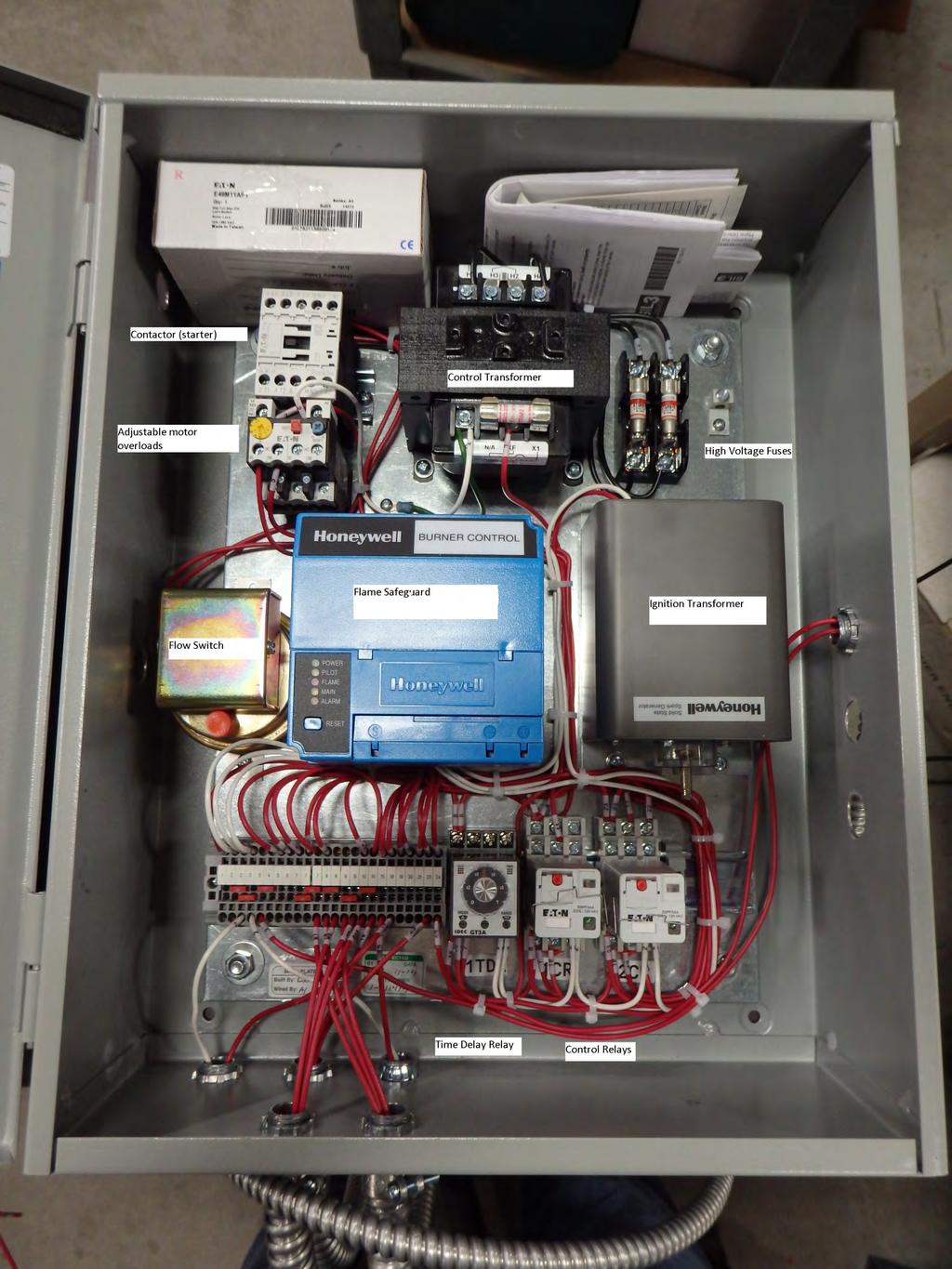
1 INSTALLATION & MAINTENANCE MANUAL GAS FIRED DOOR HEATER Series 79, DH22 AND DH24 DM018 REV 4/23/18 Order # Model # Mounting Position Wiring Dia. Symbol MFR S NAME PART NO. PUBLICATION NO. DESCRIPTION HARTZELL DM018 INSTALLATION INSTRUCTIONS CRE HONEYWELL RM7890AI056 FLAME SAFEGUARD FLS ANTUNES SMDJ DIFFERENTIAL PRESSURE SWITCH M CUTLER HAMMER XTCE SERIES SEE WIRING DIA. MOTOR STARTER WITH OVERLOADS IV ASCO JB C SAFETY SHUTOFF GAS VALVE W/POC IPS ANTUNES MANUAL LOW GAS PRESSURE SWITCH 2PS ANTUNES MANUAL HIGH GAS PRESSURE SWITCH 2THS THERM-O-DISC 60T HI TEMPERATURE LIMIT 2V ASCO SV311A02N6BF5 V8523R1 GAS PILOT VALVE SC HONEYWELL C7027A1072 FORM102 ULTRA-VIOLET SCANNER (FLAME SENSOR) HARTZELL E029REV 19 WIRING SCHEMATIC/BILL OF MATERIAL HARTZELL EP01 REV 3 PLUMBING DIAGRAM W/BILL OF MATERIAL HARTZELL DM018 INSTALLATION AND OPERATION MANUAL

2 HARTZELL GAS FIRED DOOR HEATER SERIES 79 MODELS DH22 & DH24 1. DESCRIPTION The Hartzell Gas-Fired Door Heater is designed to instantly direct a high velocity of heated air towards a large door opening, when the door is opened in cold weather. It utilizes a ring type burner operating on natural gas. The propeller is a special Hartzell Ductaxial, one piece, solid aluminum casting, direct connected to an industrial duty, totally enclosed motor. The direct fired burner was designed and is manufactured by Hartzell, based on many years of experience in the direct fired gas make up air and crop dryer markets. Products of combustion, which are discharged directly into the main airstream, consist of carbon dioxide and water vapor. At maximum rated heat output the concentration of C02 is approximately 2000 PPM (parts per million) compared with a maximum allowable* of 5000 PPM. Although the water vapor of combustion is added, relative humidity is actually reduced, owing to the heat that is added to the air. At maximum rated heat output, and assuming 60 F. saturated entering air, the discharge air is less than 5% RH. 2. MOUNTING POSITIONS (A) Burner: The standard unit may be installed at any angle between horizontal and vertical down airflow. The control cabinet is on the left-hand side, when facing the airstream. The back panel of the cabinet must lie in a vertical plane; i.e., the burner house cannot be rotated, thus rolling the cabinet toward the top or bottom of the burner house. Plumbing: The gas piping elbows up and into the burner house on the bottom centerline. During installation, by loosening the union just outside the heater, the piping train may be rotated to any desired direction, assuring gas valves are properly oriented. (See CAUTION in Section 7.) 3. INSTALLATION (MECHANICAL) One, 24 Door Heater will handle up to approximately a 12' x 16' door opening. Larger opening require two or more heaters. See sizing chart on page 3. CAUTION: No door heater can substitute for a Tempered Intake Air Unit. I f i n -plant negative pressure exists because of exhaust ventilation, a makeup air unit must be provided before a door heater can be expected to function properly. See your local Hartzell representative. Your door heater should be aimed at a spot on the floor about four or five feet inside, and midway across, the door. At the inlet end there should be no obstructions to the airflow closer than 20" - 24". At the outlet end, of course, there should be nothing obstructing the airstream. Around the sides of the heater there should be no combustible material closer than three feet. Always make sure you leave access room for maintenance.
3 Dimensions, Rating Table and Door Heater Sizing
4 4. GAS PRESSURE REGULATOR Gas pressure regulator can be specified at the time of ordering, allowing proper line pressure reduction to 6" - 8" W. C. for 24 units and 5 7 W.C. for 22 units. Regulator can be supplied by customer. It s suggested that a 1/8" or 1/4" I.P.S. test connection be provided in the gas supply line downstream of the regulator to facilitate taking pressure readings at time of startup and adjustment of burner equipment. Make sure that your regulator is installed in the line with the arrow on the body pointing in the direction of the flow of the fuel. With the regulator properly installed in the line, the following procedure is suggested when ready to light off and adjust the burner. (A) Remove the "top cap" of the regulator and check for shipping block or rod installed between spring and top cap. Remove, if found. Remove plug, in vent opening of diaphragm housing. (Connect vent to outside building, if required.by plant or insurance regulations.) The setting of the spring beneath the "top cap" on the regulator determines the outlet pressure. Screwing in on it increases the outlet pressure. Screwing out reduces the outlet pressure. The outlet pressure from the regulator will not necessarily be the same at full fire as under static conditions of no flow. Therefore, when adjusting gas pressure to very heat output, do so with the heater in operation. (See Section 9 table 1.) *** Add a gas line manual shut off valve just upstream of the regulator for maintenance reasons. 5. SUGGESTIONS FOR REGULATOR VENTING. One purpose of the vent connection is to provide a safe means of venting gas if the regulator diaphragm should fail. The vent also provides relief from the space above the diaphragm as it moves during regulation. A restriction in the vent line can result in poor regulator performance. The vent line should normally be piped outside the building, with as short a run of pipe as possible. There should be a minimum number of bends, and the pipe should be as large as practical, using the vent-hole size as a guide. When tubing is used, care must be exercised to avoid sharp bends and the resultant reduction in area. Grouping vent lines together into a common header is not normally recommended. If they must be grouped, the header cross-sectional area should be at least equal to the sum of the individual vent areas. The outside end of the vent line should either have a weatherproof vent cap or should be directed downward for weather protection. It should also be screened to prevent foreign material or insects from entering the line. Naturally, the end of the line should be located in an area where it is safe to release gas. A high percentage of regulator problems are due to improper venting. Remember the space over the diaphragm must be able to breathe for proper regulation. If there is any regulation problem, disconnect the vent line at the regulator to see if proper venting is the solution. Then look for undersized lines, crimped tubing, clogged lines, back pressure caused by draft effect at end of vent or pressure effect from other regulators in a grouped system.
5 6. INSTALLATION (ELECTRICAL). Confirm your supply voltage matches the controls ordered on this unit. It should be 230 or 460 or 575 only. All 115 volt wiring for the door switch and remote station is picked up in the control cabinet. All internal electric wiring is factory installed. It is only necessary to connect main power leads to (Ll - L2 - L3) to the disconnect switch (if provided). or top of starter contacts. Then wires between remote station, and door switch back to terminal block in units control cabinet. The remote station (see DWG E029 P2) may be installed at any location for convenience in switching the heater from "OFF" or "SUM" in warm weather or WIN for heat. The DOOR LIMIT SWITCH must be installed on the door frame in such a way that it is tripped as soon as the door begins opening. A switch having 2 poles, 1 normally open and 1 normally closed, is furnished so that whichever pole is closed by the opening of the door, it will actuate the heater. (Reference Hartzell Drawing E029). This door switch must trip as soon as your door starts up and trip again just before your door closes. This prevents large volumes of cold air to be drawn into your facility. 7. INSTALLATION (GAS PIPING) Read Section 2B. CAUTION: When making up gas piping, be sure all valves are in a horizontal portion of the gas line, with valve body properly positioned: (A) (C) (D) Main line safety valve (1V**), solenoid type. Valve is 1 with proof of closure switch and 115 volt. Pilot solenoid gas valve (2V**). Valve is ¼ and 115 Volt. Gas regulator should be mounted a few feet upstream of the unit. A manual shutoff valve should be placed just ahead (upstream) of the regulator. High and Low gas pressure switches (manual reset). See section 8 on safety devices.
6 8. SAFETY DEVICES (A) High & Low Gas Pressure Switches: Two manual switches when tripped turn on the green flame out/turn reset light on the remote station. Manual reset gas pressure switches are used for safety if supply pressure falls below or rises above the proper operating range. (See wiring diagram for proper setting.) Switches are pre-set at the factory during testing/inspection. Both switches have a vent connection for venting gas in case of a ruptured diaphragm. Connect vent to atmosphere per Section 5 above. The switches lock out if tripped, and must be manually reset. Thus, whenever gas is turned off manually, 1PS (Low Gas Pressure Switch) must be reset. (C) (D) (E) (F) (G) (H) (I) Safety Shut-Off Valve: This heater is equipped with a solenoid type gas valve with proof of closure. It s a fast-open, instant close valve meeting the requirements of FM, UL, and CGA. Valve includes proof of closure which confirms valve is closed prior to attempting ignition. Hi-Temperature Limit: The "Therm-O-Disc" limit switch is located near the discharge end of the heater, mounted on the top outside of the duct. This is a U.L. approved manual-reset device. Airflow Switch: A UL/FM approved differential pressure switch in the control cabinet senses velocity plus static pressure of the airflow from the propeller. This air pressure switch closes its contact when airflow is proved. The flame safeguard is a Honeywell RM7890A1056, which utilizes an ultraviolet flame scanner for monitoring both pilot and main flame. At any time that it doesn t sense flame when it should, or it sees flame when it shouldn t, the flame safe guard locks out which will not allow the burner to operate. When this happens, you will have to manually reset the flame safe guard in your control cabinet. Unit will start back through the ignition cycle. If electric power to the control circuit fails for any reason, whether intentional or otherwise, and no matter how briefly, the flame safeguard gives a safe start component check when power is restored. If a flame simulating component failure exists it will not proceed to the ignition cycle and will not energize the main gas valve component check when power is restored. Fan Starter: Although not normally considered a safety device, the fan starter is wired so that its interlock powers the control system. Thus the main fan must be energized before the gas system can be powered. This provides one more assurance, in addition to the Airflow Switch, that the fan is operating before heat comes on. Optional outdoor thermostat (1THS) can be provided. This thermostat will not let your unit light off if the winter mode when the outdoor temperature exceeds this thermostats setting. Both the primary and secondary sides of the control voltage transformer (1T) are protected with fuses. Motor starter overloads. Preset at Hartzell for correct motor protection.
7 9. Start UP Procedure Make sure remote station and door switch are wired and mounted Double check supply voltage matches unit. 230 or 460 or 575 volts Turn on gas and Leak check all plumbing up through gas main blocking valve. Press Manual Reset on the Low gas pressure switch. Confirm your supply gas pressure is between 5 and 9 Turn on disconnect switch From Floor level, flip remote station selector switch to SUM (fan should start) and back to off. Make sure your prop rotation is clockwise when looking in the units discharge. Turn your remote station selector switch to the WIN position and open you door. Fan should start as soon as the door starts up and within a few seconds you should be able to see a golf ball size pilot flame then almost immediate burner flame. Pilot flame will discontinue after 5 seconds. IF unit doesn t start on first try, turn remote station from winter to summer and back to winter to reset controls and let unit try again for ignition. Make a final gas pressure setting of your supply gas regulator with your unit running. See chart on page 3 of IOM for gas pressure settings. Close door and make sure unit shuts down properly. ****** On first time start-up you may need to cycle the unit two or three times to clear the gas line of air. If you are having problems during new unit start up or need technical support please contact us Direct at or and ask for one of our Make-Up Air specialist MAINTENANCE (Note: See wiring diagram for part number and manufacturer of any control component. See manufacturer's instruction sheets for more information.) (A) (C) Fan Motor Bearings: Most fan motors n o w have double shielded bearings and will never require re-lubrication. Burner: Side plates and their air holes should be checked periodically to be sure these parts are not fouled or plugged. A simple cleaning with a wire brush is required. Confirm pilot barrier is still in place. Drilling of gas ports is required every heating season. Use a #47 or 5/64 drill bit, with drill bit extension, to remove any carbon build up in these ports. (D) (E) (F) Fireye: The Honeywell RM flame safeguard utilizes solid state components. The only required maintenance is on its external components; i.e., the Ultra-Violet Scanner. U.V. Scanner: Remove scanner occasionally, clean lens with soft cloth and be sure that mounting pipe nipple is clear of insects and dirt. Spark Igniter: Ignition takes place - by means of a spark jumping from the igniter to the side plate of the burner. The spark gap should be 1/8" to 3/16 and located downstream of an air mixing hole, so there is a gas-air mixture to be ignited. Check for carbon bridge" between electrode and burner which may short out spark and prevent ignition. Remove protective boot and clean connection between ignition cable and igniter.
8 11. TROUBLE SHOOTING (A) Fan Won't Start- (1) Selector in "OFF position. (2) Check to see if motor overload relays are tripped. Press reset. (3) Check 3-phase line leads for power across all 3 phases. If one line is dead, check fuses or breaker in main disconnect. (4) Check fuse on control circuit transformer 1T. You should have 115 volts off the secondary. (5) Try "SUM setting. If fan runs, but won't run on "WIN", check I THS outdoor thermostat (if used) for open R-B contact; check limit switch on door for open contact. Fan only Operates, Gas Pilot Will Not Ignite, Green TURN RESET" Does Not Light:- (1) Selector in "SUM" position. Turn to "WIN". (2) Check wire 6 to ground 115V (defective selector switch or wiring to same). (3) Check wire 7 to ground (bad Auxiliary contact on starter). (4) 9 to ground (bad R-W contact in lo-gas switch). (5) 10 to ground (bad R-B contact in hi-gas switch). (6) 11 to ground (bad 4-5 contact in control relay). (7) 12 to ground (bad C-NO contact in airflow switch; pressure setting too high, tum adjustment screw CCW until switch trips; clogged tubing in airstream). (8) 13 to ground (reset Therm-O-Disc, inside "handy-box"). (9) Check toggle switch in mounting base of Fireye (must be left in ON position). (C) Fan Operates, Gas Pilot Will Not Ignite, Green "TURN RESET" Lights Continuously Whenever Fan Runs: (1) Defective time delay TDR. (Pull from socket, tum RESET, and try again.) (2) One or both gas pressure switches tripped. Press reset lever. If low pressure can t be reset, check for cause of inadequate pressure. Check supply pressure ahead of regulator; if pressure exceeds rating of regulator, it may pass no gas or fail to regulate. (D) Fan Operates, Gas Pilot Will Not Ignite, Green LOCKOUT Lights Continuously Whenever Fan Runs: (1) Press reset button on Fireye. (2) If Fireye won t reset, check for presence of continuous gas pilot flame.
9 CAUTION In this case turn off manual cock in pilot line before stopping fan. Then investigate cause of pilot valve IV sticking open. (3) If Fireye can be reset, but on next try-for-ignition, "TURN RESET" lights, refer to Section E or F. If "LOCKOUT" lights refer to Section G. (E) Fan Operates, Little or No Pilot Flame and "TURN RESET" Lights after 5 Seconds: (1) Check gas pilot manual cock; should be left in open position. (2) Check all gas lines for clogging and for purging of entrapped air. (3) Check for moisture and/or conducting dirt on Sparktrode; check electrode for carbon bridge to burner, which may short out ignition spark. (4) Check for adequate pilot flame. Pilot flame should be a visible golf ball size flame. (5) Take a volt reading with your VOM meter to confirm ultra-violet scanner is seeing the pilot flame. (F) Fan Operates; Pilot Ignites Normally, then Goes Out as "TURN RESET" Lights: (1) Check all manual cocks in main gas line; these should be left open in normal operation. (2) Check scanner, remove and clean lens; check mounting pipe nipple for clogging by insects, dirt, or rust. (3) With selector in WIN but unit not operating (i.e., door switch open-contact with door closed), hold match or lighter flame in front of scanner. Flame relay in Fireye chassis should pull in with audible click. If not, proceed to step 4. CAUTION- Before proceeding to step 4 or 5, tum selector to "OFF", make the changes suggested, and then return the selector to "WIN'". This is important, because in "WIN" position, the Fireye is energized and electrical shock could result. (4) Detach #20 and #21leads from installed scanner, attach a known good scanner to terminals #20 and #21,-and repeat step 3. If flame relay now pulls in, install new scanner. If not, re-install leads from original scanner and proceed to step 5. (5) Replace Fireye chassis, 'inside control cabinet, with a known good unit, and repeat step 3. If flame relay still does not pull in, have -scanner and chassis checked by Fireye distributor or by Hartzell factory. (G) Fan Operates, Pilot Ignites Normally; then Goes Out as LOCKOUT Lights: (1) With fan operating momentarily jumper circuit #7 to #8, this should result in control relay CR pulling in, lighting "TURN RESET" pilot and extinguishing "LOCKOUT". If so, insert new TDR relay (Amperite 115N05). If not, proceed to step 2. (2) With fan operating, check for 115 volts across circuits #8 and #2 (at coil connections of CR control relay). If no voltage, jumper per step 1 above. If still no voltage backtrack through circuits 8, 7, 6, and 5, to determine where break in circuit exists. If 115 volts is measure but relay does not pull in, or if relay does pull in but LOCKOUT remains lit, replace CR relay. (3) After either step 1 or 2 corrective action has been taken, continue with Sections E or F, as indicated by symptoms.
10
Indirect gas-fired air heater
 Indirect gas-fired air heater SERIES HD INSTALLATION AND SERVICE MANUAL MANUFACTURED BY : BROTHERS LIMITED WARNING Improper installation, modification, adjustment or maintenance may cause damage, injury
LATTNER BOILER COMPANY 9.5 HP Low-NOx Installation and Start-Up Checklist for Dry Cleaners
 1 1. General Installation Information (to be completed by technician) Date installed: Location (city & state): Cleaner s name: National Board number (boiler): Installed by (company): Installed by (technician):
ECLIPSE INFORMATION GUIDE
 ECLIPSE INFORMATION GUIDE JUNIOR INDUSTRIAL BURNERS Models 0 & 6 JIB Info 80 0/9 Easy to install and operate. Rugged construction for long life in industrial environments. Protection against overheating
KEES, INC. Installation & Maintenance Manual DFG Series Direct Gas Fired Make-up Air Heaters. Table of Contents FOR YOUR SAFETY.
 KEES, INC. Installation & Maintenance Manual DFG Series Direct Gas Fired Make-up Air Heaters Table of Contents FOR YOUR SAFETY Page # Topic If you smell gas: 1 Description of Operation 1 Receiving the
Packaged Gas/Electric Units. Owner s Guide to Operating and Maintaining Your Gas/Electric Unit
 Packaged Gas/Electric Units Owner s Guide to Operating and Maintaining Your Gas/Electric Unit ELECTRICAL SHOCK HAZARD. FIRE OR EXPLOSION HAZARD Disconnect power at fuse box or service panel before performing
Installation, Operation and Maintenance Instructions. for MAKE-UP AIR UNITS
 Part # 456857 Installation, Operation and Maintenance Instructions for MAKE-UP AIR UNITS with Direct Fired Gas Heater Option (for natural or LP gas) R C ETL Listed R WARNING: Improper installation, adjustment,
Flame Safeguard Fault Code Diagnostics
 Vino s Vine Tech Tips Series 02/2013 Flame Safeguard Fault Code Diagnostics As manager of Tech Services, it probably comes as no surprise I spend some time discussing fault codes and corresponding corrective
SERVICE AND INSTALLATION MANUAL MODELS HDO(H) OIL FOR YOUR SAFETY
 OIL FOR YOUR SAFETY") Bousquet Technologies Inc. 2121, Nobel, Ste Julie, Quebec, Canada, J3E1Z9 SERVICE AND INSTALLATION MANUAL MODELS HDO(H) OIL Oil-Fired air heater for industrial and commercial use. FOR YOUR SAFETY Do not
Bousquet Technologies Inc. 2121, Nobel, Ste Julie, Quebec, Canada, J3E1Z9 SERVICE AND INSTALLATION MANUAL MODELS HDO(H) OIL Oil-Fired air heater for industrial and commercial use. FOR YOUR SAFETY Do not
HEATEC TEC-NOTE. Operation and maintenance Heatec thermal fl uid heaters industrial series IMPOPRTANT NOTICE! CONTENTS. Publication No.
 HEATEC TEC-NOTE Operation and maintenance Heatec thermal fl uid heaters industrial series CONTENTS Important Notice...1 Intended users...2 Scope...2 Prior to initial startup...2 Preliminary tasks...2 Purging
USER'S MANUAL PGE Single Package Rooftop
 USER'S MANUAL PGE Single Package Rooftop Gas Heating/Electric Cooling Units Sizes 036-150 3 to 12-1/2 Tons NOTE TO INSTALLER: This manual should be left with the equipment owner. WARNING: If the information
STR-Series Indirect-Fired Air Turnover Units
 STR-Series Indirect-Fired Air Turnover Units Equipment Specifi cations 1.800.589.3691 www.weather-rite.com GAS/OIL HEATING ONLY INDIRECT-FIRED AIR TURNOVER UNIT GUIDE SPECIFICATIONS PART 1 GENERAL [Gas][Oil][Gas/Oil
Direct Fired Heater Model AD Specification
 Direct Fired Heater Model AD Specification Description A Direct-fired gas heating and ventilating unit(s), as indicated on the drawings shall be furnished. Unit(s) shall be tested in accordance with ANSI
Installation & Service Instructions for Jackson & Church Flexaire Packaged Furnaces SDF-125 thru SDF-400 Gas Firing
 Installation & Service Instructions for Jackson & Church Flexaire Packaged Furnaces SDF-125 thru SDF-400 Gas Firing Important: To protect the unit and avoid damage to the heat exchanger, the blower speed
Internal ridged board 1" x 1.5 foil face installation shall be installed on roof, walls and base of casing.
 A-D WITH MPU SPECIFICATION WRITTEN SPECIFICATION Description A Modular Packaged Heating, Cooling and ventilating unit(s), as indicated on the drawings shall be furnished. Direct Fired Gas Unit(s) shall
OWNER S MANUAL Manufactured Home Downflow Gas Furnace: MGD-B Series
 OWNER S MANUAL Manufactured Home Downflow Gas Furnace: MGD-B Series Heat Controller, Inc. 1900 Wellworth Ave. Jackson, MI 49203 (517)787-2100 www.heatcontroller.com Owner s Manual MGD-B SERIES GAS FURNACE
USERS INFORMATION MANUAL FOR GAS FIRED BOILERS
 USERS INFORMATION MANUAL FOR GAS FIRED BOILERS CATALOG NO.: 2000.52G Effective: 06-01-00 Replaces: 07-01-94 WARNING: If the information in this manual is not followed exactly, a fire or explosion may result
TEMPERATURE CONTROLLERS
 Instruction Manual: H1 T-12 Thermostat PILOT GUARD INTRODUCTION: SCOPE: This instruction manual includes installation, operation, and parts information for the Kimray Thermostat and Pilot Guard. Refer
Service Manual Model 3163
 Service Manual Model 3163 Contents Important Safety Information.......... 1 Specifications.................. 2 General Information.............. 2 Direct Vent Requirements........... 2 Propane System................
ZG Shown READ ALL INSTRUCTIONS IN THIS MANUAL AND RETAIN FOR FUTURE REFERENCE WARNING
 See unit nameplate for manufacturer and address. 507258-04 7/2018 Supersedes 10/2017 ZG 036, 048, 060, 072, 074 (3, 4, 5 and 6 Tons) ZG 092, 102, 120, 150 (7-1/2, 8-1/2, 10 and 12 Tons) ROOFTOP UNITS ZG
AXIAL HEATER TROUBLE SHOOTING GUIDE. Models: AX24 N/PV, AX24 N/PV LT, AX24 LP AX26 N/PV, AX26 N/PV LT, AX26 LP AX28 N/PV, AX28 N/PV NT, AX28 LP
 AXIAL HEATER TROUBLE SHOOTING GUIDE Page 1 July 2009 Table of Contents Frequently Asked Questions... 3 Axial Heater CONTROL (Siemens LME69) Troubleshooting Chart... 4 Axial Heater BURNER Troubleshooting
Line Pressure ( w.c.) Gas Supply Min. Max. Pressure ( w.c.) Natural Gas Propane Gas
 Gas Supply Min. Max. Pressure ( w.c.) Natural Gas Propane Gas") HVAC Guideline Specifications WHISPER-JET: SET SERIES Two Stage Positive Pressure Gas-Fired Infrared Radiant Tube Type Heater Commercial/Industrial Applications Technical Summary Input Range: 80,000/60,000
HVAC Guideline Specifications WHISPER-JET: SET SERIES Two Stage Positive Pressure Gas-Fired Infrared Radiant Tube Type Heater Commercial/Industrial Applications Technical Summary Input Range: 80,000/60,000
User s Information Manual
 48AJ,AK,AW,AY020-060 Single-Package Rooftop Gas Heating Units with COMFORTLINK Controls and Scroll Compressors User s Information Manual NOTE TO INSTALLER This manual should be left with the equipment
User s Information Manual
 48N2,N3,N4,N5,N6,N7,N8,N9 75-150 Ton Gas Heating/Electric Cooling Units with ComfortLink Controls User s Information Manual NOTE TO INSTALLER: This manual should be left with the equipment owner. : If
24 VAC SYSTEM CONTROL KIT
 24 VAC SYSTEM CONTROL KIT Model: CK-92F and CK-92FG Designed for use with the SWG Series Power Venter for controlling Natural Gas or L.P. Gas appliances with a 24 VAC Gas Valve and a 30-millivolt controlled
Packaged Gas/Electric
 Packaged Gas/Electric Units Owner's Guide to Operating and Maintaining Your Gas/Electric Unit ELECTRICAL SHOCK HAZARD. FIRE OR EXPLOSION HAZARD Failure to follow this warning can result in Disconnect power
Burn Easy Installation Instructions LP or Natural Gas Fired Units. Cremator Setup:
 Burn Easy Installation Instructions LP or Natural Gas Fired Units Cremator Setup: 1. Place cremator, outdoor on a solid base consisting of concrete or gravel. Keep this site free of all vegetation. Combustibles
INSTALLATION & MAINTENANCE MANUAL FOR QuickDraw
 INSTALLATION & MAINTENANCE MANUAL FOR QuickDraw SEMI-INSTANTANEOUS ENERGY: STEAM TO WATER U-TUBE SINGLE-WALL & DOUBLE-WALL HEAT EXCHANGERS FLOOR DRAIN Typical Construction Figure 34-1 FLOOR DRAIN 1. U-tube
Eclipse 90 UV Scanner Model A Version 1
 85 Instruction Manual 10/14/010 Eclipse 90 UV Model 5600-90A Version 1 C US Introduction This sensor features a high sensitivity ultraviolet (UV) tube for monitoring gas or oil flames that cycle on and
Fire Bowls and Fire Bowl Inserts (Automated Operation) Operating and Maintenance Instructions
 Operating and Maintenance Instructions") Table of Contents Section 1: Gas and Electric Requirements... 1 Section 2: Installation... 2 Section 3: Burner Setup and Adjustment... 8 Burner Adjustment... 9 Section 4: Maintenance... 10 Section 5: Operation...
Table of Contents Section 1: Gas and Electric Requirements... 1 Section 2: Installation... 2 Section 3: Burner Setup and Adjustment... 8 Burner Adjustment... 9 Section 4: Maintenance... 10 Section 5: Operation...
TECHNICAL SERVICE DEPARTMENT Technical Service Bulletin Ultra Low NOx PowerVent with Honeywell Electronic Control California Only
 Error Code Flash TECHNICAL SERVICE DEPARTMENT Gas Valve Status Flash Code Short flash once every four seconds "Heartbeat", alternates bright/dim One Flash, three second pause Two Flash, three second pause
BGH Series Hot Surface Ignition Control
 Installation Instructions BGH Series Issue Date April 14, 2011 BGH Series Hot Surface Ignition Control Application The BASO Gas Products BGH Series Hot Surface Ignition (HSI) control is microprocessor
24 VAC SYSTEM CONTROL KIT
 24 VAC SYSTEM CONTROL KIT Model: CK-91F and CK-91FG Designed for use with the SWG Series Power Venter for controlling Natural Gas or L.P. Gas draft induced appliances with a 24 VAC Gas Valve and a 30-millivolt
User s Information Manual
 62DA,DB,DC,DD07-38 Vertical or Horizontal Dedicated 100% Outdoor Air Unit with Optional Gas Heat User s Information Manual NOTE TO INSTALLER This manual should be left with the equipment owner. : If the
FIREYE M4RT1 FLAME SAFEGUARD CONTROLS DESCRIPTION
 M-4000 JANUARY 29, 200 FIREYE M4RT1 FLAME SAFEGUARD CONTROLS WARNING: Selection of this control for a particular application should be made by a competent professional, licensed by a state or other government
ELECTRONIC FLAME SUPERVISION MULTI-BURNER
 MULTI-BURNER MODEL: SENS-A-FLAME II Revision: 0 7112 DESCRIPTION Model 7112 Sens-A-Flame II is a second generation solid-state programmable combustion safeguard for supervising multiple burner ovens, furnaces,
FURNACE OPERATION OVERVIEW
 You ve had a fun day but now it s getting chilly, so you decide to fire up the RV furnace. You flip the thermostat on, set the temperature and wait expectantly, but no heat comes from the outlets. It s
USER S INFORMATION MANUAL
 USER S INFORMATION MANUAL HOT WATER HEATING BOILERS DOMESTIC WATER HEATERS 150,000-300,000 Btu/hr MODELS EB-EWU-02 IMPORTANT INSTALLER - AFFIX INSTALLATION MANUAL ADJACENT TO THE BOILER CONSUMER - RETAIN
Technical Data TYPE T14 & T14D TEMPERATURE PILOT SPENCE ENGINEERING COMPANY, INC. 150 COLDENHAM ROAD, WALDEN, NY SD 4511A T14 PILOT
 Technical Data SD 4511A SPENCE ENGINEERING COMPANY, INC. 150 COLDENHAM ROAD, WALDEN, NY 12586-2035 TYPE T14 & T14D TEMPERATURE PILOT PRINTED IN U.S.A. SD 4511A/9811 5 13 /16 D 4 7 /8 1 13 /16 T14 PILOT
UV Scanner. Model Specification. Introduction. 854 Instruction Manual
 854 Instruction Manual 10/11/010 UV Model 5600-91 C US Introduction This sensor features a high temperature and high sensitivity ultraviolet (UV) tube for monitoring gas or oil flames in applications that
Electrical. Bi-Metallic Thermal Cutouts. Linear Thermal Cutouts
 Standard Construction Control Options HEATREX offers a broad range of electrical components for temperature, safety, and power control. For most applications, the Control Option system, described in the
USER S, MAINTENANCE and SERVICE INFORMATION MANUAL
 CONTENTS SAFETY INFORMATION................ 2 FOR YOUR SAFETY....................... 2 SYSTEM OPERATION.................. 2 THERMOSTATS.......................... 2 INTERMITTENT IGNITION DEVICE...........
PART 0 A/E INSTRUCTIONS 0.01 DESIGN REQUIREMENTS
 PART 0 A/E INSTRUCTIONS 0.01 DESIGN REQUIREMENTS A. General: 1. To obtain maintenance and repair standards for boiler burners (Section 15555A) and boiler tubes (Section 15555B), contact the DPS Project
KG 092 SHOWN READ ALL INSTRUCTIONS IN THIS MANUAL AND RETAIN FOR FUTURE REFERENCE WARNING
 See unit nameplate for manufacturer and address. 507350-03 3/2016 Supersedes 9/2015 KG 024, 030, 036, 048, 060, 072, 074, 090 (2, 2-1/2, 3, 4, 5, 6 and 7-1/2 Tons) KG 092, 102, 120, 150 (7-1/2, 8 1/2,
Fig. 1 - Unit PGD4, PGS4, WPG4
 OWNER S MANUAL 14 SEER Single -Package Air Conditioner and Gas Furnace System with R -410A Refrigerant Single Phase 2 to 5 Nominal Tons Three Phase 3 to 5 Nominal Tons PGD4andPGS4SeriesE,WPG4SeriesB Fig.
120 VAC SYSTEM CONTROL KIT
 120 VAC SYSTEM CONTROL KIT Designed for use on SWG Series Power Vent Hoods for controlling oil fired heating appliances with 120 VAC controls. Model: CK-63 The CK-63 control has the ability to operate
WD7664 / WD7663 Maxon Burner Ellis Whisper Dryer Installation & Start UP
 WD7664 / WD7663 Maxon Burner Ellis Whisper Dryer Installation & Start UP Receiving Do a quick visual inspection on the truck for any major damage prior to signing the paperwork. Damage should be noted
KGA092 SHOWN READ ALL INSTRUCTIONS IN THIS MANUAL AND RETAIN FOR FUTURE REFERENCE WARNING
 See unit nameplate for manufacturer and address. 506380 01 11/2009 KGA024, 030, 036, 048, 060, 072 (2, 2 1/2, 3, 4, 5, and 6 Tons) KGA092, 102, 120, 150 (7 1/2, 8-1/2, 10, and 12 Tons) KGA180, 210, 240,
Engineering Bulletin. Gas Heat. for M-Series and T-Series Climate Changer Air Handlers CLCH-PRB010-EN. March 2004
 Engineering Bulletin Gas Heat for M-Series and T-Series Climate Changer Air Handlers March 2004 CLCH-PRB010-EN Preface Gas heat can be a good heating option for any of the following applications: Climates
USER S INFORMATION MANUAL (2,4)SG13B
SG13B") USER S INFORMATION MANUAL (2,4)SG13B Series Gas Heating/Electric Cooling Package Unit Congratulations......your outdoor heating/cooling package unit is a valuable piece of equipment, designed and manufactured
USER S INFORMATION MANUAL (2,4)SG13B Series Gas Heating/Electric Cooling Package Unit Congratulations......your outdoor heating/cooling package unit is a valuable piece of equipment, designed and manufactured
FEATURES AND BENEFITS
 FEATURES AND BENEFITS Product Features and Benefits Full Product Line Offering Feature All models are 80% thermally efficient Blower performance up to 3.0 W.C. DX or chilled water section with factory
A. Product Data: Include rated capacities, furnished specialties and accessories.
 BASE BID: SECTION 15542 FUEL-FIRED RADIANT HEATERS PART 1 - GENERAL 1.1 SUMMARY A. Furnish and install a Co-Ray-Vac Low Intensity Vented Infrared Radiant Vacuum Gas Heating System. System must be certified
Corn Flame Energy Corn Stove Model 3000
 Corn Flame Energy Corn Stove Model 3000 Installation and Operation Guide Read thoroughly before starting installation Save this manual for future reference SAFETY NOTICE If this stove is not properly installed,
USER S, MAINTENANCE and SERVICE INFORMATION MANUAL
 CONTENTS SAFETY INFORMATION................ 2 FOR YOUR SAFETY...................... 2 SYSTEM OPERATION.................. 2 THERMOSTATS.......................... 2 INTERMITTENT IGNITION DEVICE..........
Dexter Industrial On Premise Dryer. Troubleshooting, Fault Codes, And Schematics. Starting serial number Part # /13
 Dexter Industrial On Premise Dryer Troubleshooting, Fault Codes, And Schematics Starting serial number Dryer Trouble Shooting Symptom Probable Cause Suggested Remedy Tumbler does not turn Drive belts Check
USER S INFORMATION MANUAL
 USER S INFORMATION MANUAL UPFLOW/HORIZONTAL & DOWNFLOW TWO STAGE INDUCED DRAFT GAS FURNACES Recognize this symbol as an indication of Important Safety Information If the information in this manual is not
Gas-Fired Indoor and Outdoor Duct Furnaces
 July, 2008 Gas-Fired Indoor and Outdoor Duct Furnaces INDOOR GRAVITY VENTED DFG, DBG, DCG INDOOR SEPARATED COMBUSTION DFS, DBS, DCS OUTDOOR GRAVITY AND POWER EXHAUSTED H Series table of contents A complete
Construction Electrical
 INDEECO offers a broad range of electrical components for temperature, safety, and power control. For most applications, the Control Option system, described in the previous section, makes it easy to specify
SYSTEM CONTROL KIT. Model: CK-62. Designed for use on SWG Series Power Vent Hoods for controlling oil fired heating appliances with 120 VAC controls.
 SYSTEM CONTROL KIT Model: CK-62 Designed for use on SWG Series Power Vent Hoods for controlling oil fired heating appliances with 120 VAC controls. ITEMS INCLUDED IN KIT: 1) Junction box with mounted pressure
LGB Gas fired boiler
 LGB Gas fired boiler Control Supplement LGB-5 Series 2 Propane gas CSD-1 Control System Part Number 550-110-682/0304 Please read this page first Hazard definitions To the installer... The following terms
SECTION GAS-FIRED RADIANT HEATERS
 SECTION 23 55 23 PART 1 - GENERAL 1.1 DESCRIPTION SPEC WRITER NOTES: 1. Use this section only for NCA projects. 2. Delete between // // if not applicable to project. Also delete any other item or paragraph
Owner s Information Manual
 48ES---A and 48VL---A Comfort and Performance 13 and 14 SEER Single Packaged Air Conditioner and Gas Furnace System With Puron (R---410A) Refrigerant Single and Three Phase 2---5 Nominal Tons (Sizes 24---60)
Installation & Maintenance Instructions
 B2451 & B2452 Series Wall Heaters SPECIFICATIONS MODEL VOLTS HZ AMPS WATTS BTUH B2451 120 60 12.5 1500 5120 B2452 240 60 8.3 2000 6826 208 60 7.2 1500 5120 DIMENSIONS OVERALL Height - 14 1/4 Width - 11
National Comfort Products 539 Dunksferry Road Bensalem, PA (215) Fax: (215)
 Fax: (215)") National Comfort Products 539 Dunksferry Road Bensalem, PA 19020 (215) 244-1400 1-800-523-7138 Fax: (215) 639-1674 14299575-10/29/2014 NOTE: These installation and maintenance instructions should be left
National Comfort Products 539 Dunksferry Road Bensalem, PA 19020 (215) 244-1400 1-800-523-7138 Fax: (215) 639-1674 14299575-10/29/2014 NOTE: These installation and maintenance instructions should be left
Dexter Commercial Vended Stack Washer Dryer. Dryer Troubleshooting, Fault Codes, And Schematics. Starting serial number (12/13)
") Dexter Commercial Vended Stack Washer Dryer Dryer Troubleshooting, Fault Codes, And Schematics Starting serial number 481983 8533-070-001 (12/13) Dryer Trouble Shooting Electronic Control Diagnostic Lights
Dexter Commercial Vended Stack Washer Dryer Dryer Troubleshooting, Fault Codes, And Schematics Starting serial number 481983 8533-070-001 (12/13) Dryer Trouble Shooting Electronic Control Diagnostic Lights
24 VAC SYSTEM CONTROL KIT Model: CK-91F and CK-91FG
 24 VAC SYSTEM CONTROL KIT Model: CK-91F and CK-91FG Designed for use with the SWG Series Power Venter for controlling Natural Gas or L.P. Gas draft induced appliances with a 24 VAC Gas Valve and a 30-millivolt
WD7664 / WD7663 Maxon Burner. Ellis Whisper Dryer Installation & Start UP
 Title WD7664 / WD7663 Maxon Burner Ellis Whisper Dryer Procedure No. Installation & Start UP Procedure Author Chris Giordano Effective 1/23/17 Revision A Submitted By Chris Giordano Supersedes Date Revision
Distributed By: M&M Control Service, INC
 Sales@mmcontrol.com APPROVED The information provided in this bulletin is directed to competent boiler and combustion service technicians who are experienced in the installation and operation of Fireye
MBCE-110/230UV Flame Sensor Module
 MBCE-1002 FEBRUARY 3, 2017 MBCE-110/230UV Flame Sensor Module DESCRIPTION The MBCE-110/230UV modules provide visual indication and electrical outputs that signal the user regarding flame presence in a
southbend A MIDDLEBY COMPANY INSTALLATION AND OPERATION MANUAL CG214 (E) CG314 (E) CG414 (E) CG220 (E) CG320 (E) CG325 (E) GAS BOILERS MODELS:
 CG314 (E) CG414 (E) CG220 (E) CG320 (E) CG325 (E) GAS BOILERS MODELS:") INSTALLATION AND OPERATION MANUAL GAS BOILERS MODELS: CG214 (E) CG314 (E) CG414 (E) CG220 (E) CG320 (E) CG325 (E) southbend A MIDDLEBY COMPANY 1100 Old Honeycutt Road Fuquay-Varina, NC 27526 (919) 552-9161
INSTALLATION AND OPERATION MANUAL GAS BOILERS MODELS: CG214 (E) CG314 (E) CG414 (E) CG220 (E) CG320 (E) CG325 (E) southbend A MIDDLEBY COMPANY 1100 Old Honeycutt Road Fuquay-Varina, NC 27526 (919) 552-9161
Distributed By: M&M Control Service, INC
 APPROVED The UV1A3/6, UV2/UV2A6/UV2C, 45UV2, 45UV3, UV90-3/6/9 Scanners are used with the M-Series, M-Series II, MicroM, FlameWorx, MB-2 and D-Series controls as well as the Fireye FLAME-MONITOR TM, BurnerLogix
Type CG Series Forced Draft Gas Burner
 Type CG Series Forced Draft Gas Burner Designed and built by Canadians for Canadian Winters By PENDELL BURNERS Office & Plant Address: 155 Regina Road, Unit #3 Woodbridge, Ontario L4L 8L9 Telephone: (416)
TGIF-1. Indirect Fired Heating Systems. Technical Guide for: IF Indoor Installations. IFW Outdoor Installations. Applied Air. Keeps You.
 TGIF- Indirect Fired Heating Systems Technical Guide for: IF Indoor Installations IFW Outdoor Installations Applied Air Keeps You Warm Indirect Fired Heating Systems Technical Guide In the business of
Columbia Boiler Company
 EMG Series Boilers Available in Natural Gas & Propane Rev 12012 Columbia Boiler Company PO Box 1070 Pottstown, PA 19464 Tel (610) 473-8457 Fax (610) 367-6800 Website www.columbiaboiler.com Email cbcsales@ptd.net
QHT Manual for: SU-2A Gas Burner
 1 QHT Manual for: SU-2A Gas Burner 50,000 BTU/H to 250,000 BTU/H The burner shall be used only with NATURAL GAS or LP GAS. Warning: If the following instructions are not followed exactly, a fire or explosion
POWDER GUIDE. Trouble shooting tips to maximise the benefits of Apcoshield Powder Coatings
 POWDER GUIDE From ASIAN PAINTS (I) LTD Trouble shooting tips to maximise the benefits of Apcoshield Powder Coatings Section A : Powder Application Problems Trouble Possible Causes Solutions 1. Poor charging
MULTIPLEX SELF RECUPERATIVE gas burner
 Installation - Maintenance MULTIPLEX SELF RECUPERATIVE gas burner SERIES MPSR The Nu-way Multiplex Recuperative System offers the alternative of a self-recuperative burner or a separate recuperator and
T-SERIES Air Conditioner. T43 Model INSTRUCTION MANUAL nvent Rev. I P/N
 T-SERIES Air Conditioner T43 Model INSTRUCTION MANUAL Rev. I P/N 10-1008-145 TABLE OF CONTENTS Warranty and Return Policy...2 IMPORTANT NOTICE...2 RECEIVING THE AIR CONDITIONER...3 HANDLING AND TESTING
THC 85 INDUSTRIAL / COMMERCIAL SPACE HEATER
 A Division of THC 85 INDUSTRIAL / COMMERCIAL SPACE HEATER Certified to / Certifié à CGA 2.14 M2000 Conforms to / Conforme à ANSI std Z83.7 2000 Suitable for indoor or outdoor installation / Unvented /
TGA/KGA024, 030, 036, 048, 060, 072, 090 (2, 2 1/2, 3, 4, 5, 6, and 7 1/2 TONS)
") See unit nameplate for manufacturer and address. 506003 01 5/2009 Supersedes 1/2008 TGA/KGA024, 030, 036, 048, 060, 072, 090 (2, 2 1/2, 3, 4, 5, 6, and 7 1/2 TONS) TGA090, 102, 120, 150, TGA120 SHOWN (7
See unit nameplate for manufacturer and address. 506003 01 5/2009 Supersedes 1/2008 TGA/KGA024, 030, 036, 048, 060, 072, 090 (2, 2 1/2, 3, 4, 5, 6, and 7 1/2 TONS) TGA090, 102, 120, 150, TGA120 SHOWN (7
Power Flame Incorporated
 Power Flame Incorporated SUGGESTED SPECIFICATION FOR MODEL NVC2 THRU NVC6 ULTRA LOW NOx GAS BURNERS SUB 9 PPM NOx WITH CONTROLINKS CONTROLS THE POWER TO MANAGE ENERGY 2001 South 21st Street, Parsons, Kansas
Series 1140 and 1141 Temperature Regulators
 Hoffman Specialty Installation & Maintenance Instructions HS-504(E) Series 1140 and 1141 Temperature Regulators! CAUTION FOLLOW ALL INSTALLATION AND OPERATING INSTRUCTIONS. TURN OFF WATER OR STEAM BEFORE
ADF/ADFH 300 and 500
 MODEL ADF/ADFH DIRECT-FIRED SYSTEMS TECHNICAL DATA Four Sizes - 300, 500, 700, 1200 Horizontal Configuration with Full Curb Cap Base Horizontal or Vertical (down) Discharge Indoor/Outdoor Installation
Field Start-Up Sheet Direct Fired Gas Equipment
 Customer: Sales Representative: Model Number: Serial Number: Field Start-Up Sheet Direct Fired Gas Equipment ***Please Print*** INITIAL INSPECTION I. Installer Responsibilities 1. Remote Panel: All interconnecting
Industrial Space Heating Direct Gas-Fired Heating. Greenheat 50/50 Recirculation
 Industrial Space Heating Direct Gas-Fired Heating Greenheat 00% Outdoor Air Greenheat 50/50 Recirculation 80/0 Recirculation March 008 Product Overview Industrial Space Heating Greenheck s space heating
THC 85N / 175N INDUSTRIAL / COMMERCIAL SPACE HEATER
 THC 85N / 175N INDUSTRIAL / COMMERCIAL SPACE HEATER Certified to / Certifié à CGA 2.14 M2000 Conforms to / Conforme à ANSI std Z83.7 2000 Suitable for indoor or outdoor installation / Unvented / Unattended
MODEL ADF/ADFH 300 and 500 INDOOR/OUTDOOR DIRECT-FIRED GAS HEATING/MAKEUP AIR SYSTEM FOR INDUSTRIAL & COMMERCIAL APPLICATIONS
 MODEL ADF/ADFH 300 and 500 FOR INDUSTRIAL & COMMERCIAL APPLICATIONS Model ADF CSA 3.7 ANSI Z83.4 Non-Recirculating Industrial Air Heaters WARNING: GAS-FIRED APPLIANCES ARE NOT DESIGNED FOR USE IN HAZARDOUS
G71MPP WARNING. WARNING Sharp edges. Be careful when servicing unit to avoid sharp edges which may result in personal injury. Service Literature
 Service Literature Corp. 0804 L2 Revised 05 05 2008 G71MPP G71MPP SERIES UNITS G71MPP series units are high efficiency multi position (upflow, downflow, horizontal right and left) gas furnaces equipped
FIREYE C9707A ALL FUEL SCANNER
 65-8065 APRIL 11, 2013 FIREYE C9707A ALL FUEL SCANNER The C9707A All Fuel Scanner is used with the FIREYE R9107A Flame Controller to provide continuous monitoring of burner flames in industrial and utility
Fully-automatic Gas tankless Water Heater USER'S MANUAL FOR MODEL EZ-101 ISO9001 certified
 Fully-automatic Gas tankless Water Heater USER'S MANUAL FOR MODEL EZ-101 ISO9001 certified Thank you for purchasing our fully-automatic gas-fired tankless water heater. Please completely read this Manual
User s Information Manual
 48TJD005-014 48TJE004-014 48TJF004-012 Single-Package Rooftop Heating/Cooling Units User s Information Manual NOTE TO INSTALLER This manual should be left with the equipment owner. FOR YOUR SAFETY Do not
V SERIES HDR GAS RANGES
 SERVICE MANUAL ONE POWERFUL PACKAGE V SERIES HDR GAS RANGES TOPS Open Top Hot Top Griddle Top Work Surface BASES Standard Oven Convection Oven Cabinet Base - NOTICE - This manual is prepared for use by
user s information manual
 user s information manual SINGLE PACKAGE ROOFTOP GAS HEATING/ELECTRIC COOLING UNITS 580F Sizes 036-150 3 to 12 1 / 2 Tons Cancels: New OM11-18 10/15/00 NOTE TO INSTALLER This manual should be left with
Refer to the Page 23 (inside back cover) for Model Nomenclature. Table of Contents
 for Model Nomenclature. Table of Contents") TABLE OF CONTENTS A complete line of commercial, industrial, and residential heating equipment is offered. This catalog describes in detail the gas-fired, gravity and power vented, commercial/ industrial
TABLE OF CONTENTS A complete line of commercial, industrial, and residential heating equipment is offered. This catalog describes in detail the gas-fired, gravity and power vented, commercial/ industrial
Owner's Guide to Operating and Maintaining Your Gas/Electric Unit
 Packaged Gas Heat/Electric Cooling Units Owner's Guide to Operating and Maintaining Your Gas/Electric Unit ELECTRICAL SHOCK. FIRE OR EXPLOSION Failure to follow this warning could result in personal injury,
Refer to Bulletin E-1101 for detailed information on the FLAME-MONITOR System.
 The Fireye EP260, EP270 (early spark termination), or EP265 (pilot stabilization) programmer modules are used with the FLAME-MONITOR Burner Management Control System (P/N E110). Several operational characteristics
PBG PACKAGED GAS BURNER
 INSTRUCTIONS PBG PACKAGED GAS BURNER WARNING These instructions are intended for use only by experienced, qualified combustion start-up personnel. Adjustment of this equipment and its components by unqualified
HG Million Btu/Hr Gas-Fired Heater
 HG-1-1142 1-Million Btu/Hr Gas-Fired Heater PAGE -2 of 30 HG-1-1142 GAS-FIRED HEATER Table of Contents Warnings... 1-2 Specifications... 3 Preliminary Checks Prior to Initial Operation... 4 Adjusting the
Title: YALE OFFICE OF FACILITIES PROCEDURE MANUAL Chapter: 01 - Yale Design Standard Division: HVAC Standards
 Date Description of Change Pages / Sections Modified ID 6/15/16 Entire document - mgl44 PART 1 - INTRODUCTION 1.1 PURPOSE A. This section is intended to define the general installation and minimum product
Service Manual For model N260 - a 2.4 cu. ft., 2-way refrigerator. For model N a 2.4 cu. ft., 3-way refrigerator.
 Service Manual For model N260 - a 2.4 cu. ft., 2-way refrigerator. For model N260.3 - a 2.4 cu. ft., 3-way refrigerator. NORCOLD, Inc. P.O. Box 4248 Sidney, OH 45365-4248 Part No. 619260A (4-98) Table
G60UH(X) WARNING. WARNING Sharp edges. Be careful when servicing unit to avoid sharp edges which may result in personal injury. Service Literature
 WARNING. WARNING Sharp edges. Be careful when servicing unit to avoid sharp edges which may result in personal injury. Service Literature") Service Literature Corp. 0204 L2 Revised 11 2006 G60UH(X) G60UH(X) SERIES UNITS G60UH(X) series units are mid efficiency gas furnaces used for upflow or horizontal applications only, manufactured with
Service Literature Corp. 0204 L2 Revised 11 2006 G60UH(X) G60UH(X) SERIES UNITS G60UH(X) series units are mid efficiency gas furnaces used for upflow or horizontal applications only, manufactured with