TECHNICAL & SERVICE MANUAL
|
|
|
- Adela Riley
- 5 years ago
- Views:
Transcription
1 TECHNICAL & SERVICE MANUAL INDOOR UNIT: MCAF94MR5IAA MCAF124MR5IAA MCAF184MR5IAA MCAF244MR5IAA NOV.2003 Destination: General area (50Hz) Europe (50Hz) Australia (50Hz) General area (60Hz) DC INVERTER MULTI-SYSTEM AIR CONDITIONER Capacity Indoor Model No. Product Code No. 2.8 kw 3.6 kw 5.0 kw 7.0 kw MCAF94MR5IAA MCAF124MR5IAA MCAF184MR5IAA MCAF244MR5IAA Wall Mounted Type Indoor Unit < Combined Outdoor unit > GRF194MR5IAA (2-room multi unit) AGRF244MR5IAA (3-room multi unit) GRF314MR5IAA (4-room multi unit) MCAF94MR5IAA NOTE 1. The indoor unit MCAF244MR5IAA can only be combined with a 4-room multi unit. Therefore, do not combine it with a 2- room multi unit or 3-room multi unit. 2. For details about the combinations, refer to Unit Combination Table in the T. Service Manual for the Multi Outdoor Units. MCAF124MR5IAA MCAF184MR5IAA IMPORTANT These air conditioners employ new refrigerant R410A. Pay special attention when servicing the unit. MCAF244MR5IAA W
2 Table of Contents Page 1. OPERATING RANGE SPECIFICATIONS 2-1. Unit Specifications Major Component Specifications Other Component Specifications DIMENSIONAL DATA REFRIGERANT FLOW DIAGRAM PERFORMANCE DATA 5-1. Air Throw Distance Chart ELECTRICAL DATA 6-1. Electrical Characteristics INSTALLATION INSTRUCTIONS 7-1. Indoor Unit Connecting Indoor Units Test Run FUNCTIONS 8-1. Operation Functions Protective Functions TROUBLESHOOTING APPENDIX ii
3 Important! Please Read Before Starting This air conditioning system meets strict safety and operating standards. As the installer or service person, it is an important part of your job to install or service the system so it operates safely and efficiently. For safe installation and trouble-free operation, you must: Carefully read this instruction booklet before beginning. Follow each installation or repair step exactly as shown. Observe all local, state, and national electrical codes. Pay close attention to all warning and caution notices given in this manual. This symbol refers to a hazard or WARNING unsafe practice which can result in severe personal injury or death. This symbol refers to a hazard or CAUTION unsafe practice which can result in personal injury or product or property damage. If Necessary, Get Help These instructions are all you need for most installation sites and maintenance conditions. If you require help for a special problem, contact our sales/service outlet or your certified dealer for additional instructions. In Case of Improper Installation The manufacturer shall in no way be responsible for improper installation or maintenance service, including failure to follow the instructions in this document. Special Precautions WARNING When Wiring ELECTRICAL SHOCK CAN CAUSE SEVERE PERSONAL INJURY OR DEATH. ONLY A QUALIFIED, EXPERIENCED ELECTRICIAN SHOULD ATTEMPT TO WIRE THIS SYSTEM. Do not supply power to the unit until all wiring and tubing are completed or reconnected and checked. Highly dangerous electrical voltages are used in this system. Carefully refer to the wiring diagram and these instructions when wiring. Improper connections and inadequate grounding can cause accidental injury or death. Ground the unit following local electrical codes. Connect all wiring tightly. Loose wiring may cause overheating at connection points and a possible fire hazard. When Transporting Be careful when picking up and moving the indoor and outdoor units. Get a partner to help, and bend your knees when lifting to reduce strain on your back. Sharp edges or thin aluminum fins on the air conditioner can cut your fingers. When Installing In a Ceiling or Wall Make sure the ceiling/wall is strong enough to hold the unit s weight. It may be necessary to construct a strong wood or metal frame to provide added support. In a Room Properly insulate any tubing run inside a room to prevent sweating that can cause dripping and water damage to walls and floors. In Moist or Uneven Locations Use a raised concrete pad or concrete blocks to provide a solid, level foundation for the outdoor unit. This prevents water damage and abnormal vibration. In an Area with High Winds Securely anchor the outdoor unit down with bolts and a metal frame. Provide a suitable air baffle. In a Snowy Area (for Heat Pump-type Systems) Install the outdoor unit on a raised platform that is higher than drifting snow. Provide snow vents. When Connecting Refrigerant Tubing Use the flare method for connecting tubing. Apply refrigerant lubricant to the matching surfaces of the flare and union tubes before connecting them, then tighten the nut with a torque wrench for a leakfree connection. Check carefully for leaks before starting the test run. When Servicing Turn the power off at the main power box (mains) before opening the unit to check or repair electrical parts and wiring. Keep your fingers and clothing away from any moving parts. Clean up the site after you finish, remembering to check that no metal scraps or bits of wiring have been left inside the unit being serviced. Others CAUTION Ventilate any enclosed areas when installing or testing the refrigeration system. Escaped refrigerant gas, on contact with fire or heat, can produce dangerously toxic gas. Confirm upon completing installation that no refrigerant gas is leaking. If escaped gas comes in contact with a stove, gas water heater, electric room heater or other heat source, it can produce dangerously toxic gas. Do not install only a single indoor unit. i
4 1. OPERATING RANGE Cooling Heating Temperature Indoor Air Intake Temp. Outdoor Air Intake Temp. Maximum 32 C D.B. / 23 C W.B. 43 C D.B. Minimum 19 C D.B. / 14 C W.B. 19 C D.B. Maximum 27 C D.B. 24 C D.B. / 18 C W.B. Minimum 16 C D.B. / 15 C W.B. 1
5 2. SPECIFICATIONS 2-1. Unit Specifications Indoor Unit MCAF94MR5IAA Type Wall hang type indoor unit Power Source V ~ 50Hz 220V ~ 60Hz Voltage rating 230 V 220 V Performance Cooling Heating Cooling Heating Capacity kw 2.8 ( ) 4.0 ( ) 2.8 ( ) 4.0 ( ) Air circulation (Hi / Me / Lo) m 3 /h 620 / 510 / / 520 / / 510 / / 520 / 460 Moisture removal (High) Liters/h Electrical Rating Cooling Heating Cooling Heating Available voltage range V 198 ~ ~ 242 Running amperes A Power input W Features Controls / Temperature control Microprocessor / I.C. thermostat Control unit Wireless remote control unit Timer ON/OFF 24 hours & Daily program,1-hour OFF Fan speeds 3 and Auto Airflow direction (Indoor) Horizontal Manual Vertical Auto Air filter Washable, Anti-Mold Operation sound Hi / Me / Lo db-a 41 / 38 / / 39 / / 38 / / 39 / 34 Refrigerant tubing connections Flare type Refrigerant Narrow tube mm (in.) 6.35(1/4) tube diameter Wide tube mm (in.) 9.52(3/8) Refrigerant g R410A Refrigerant tube kit Optional Dimensions & Weight Unit dimensions Height mm 275 Width mm 805 Depth mm 178 Package dimensions Height mm 335 Width mm 860 Depth mm 252 Weight Net kg 8.5 Shipping kg 12 Shipping volume m DATA SUBJECT TO CHANGE WITHOUT NOTICE. 2
6 Indoor Unit MCAF124MR5IAA Type Wall hang type indoor unit Power Source V ~ 50Hz 220V ~ 60Hz Voltage rating 230 V 220 V Performance Cooling Heating Cooling Heating Capacity kw 3.6 ( ) 4.8 ( ) 3.6 ( ) 4.8 ( ) Air circulation (Hi / Me / Lo) m 3 /h 580 / 450 / / 600 / / 450 / / 600 / 500 Moisture removal (High) Liters/h Electrical Rating Cooling Heating Cooling Heating Available voltage range V 198 ~ ~ 242 Running amperes A Power input W Features Controls / Temperature control Microprocessor / I.C. thermostat Control unit Wireless remote control unit Timer ON/OFF 24 hours & Daily program,1-hour OFF Fan speeds 3 and Auto Airflow direction (Indoor) Horizontal Manual Vertical Auto Air filter Washable, Anti-Mold Operation sound Hi / Me / Lo db-a 46 / 39 / / 40 / / 39 / / 40 / 34 Refrigerant tubing connections Flare type Refrigerant Narrow tube mm (in.) 6.35(1/4) tube diameter Wide tube mm (in.) 9.52(3/8) Refrigerant g R410A Refrigerant tube kit Optional Dimensions & Weight Unit dimensions Height mm 285 Width mm 805 Depth mm 219 Package dimensions Height mm 342 Width mm 859 Depth mm 289 Weight Net kg 9.5 Shipping kg 12 Shipping volume m DATA SUBJECT TO CHANGE WITHOUT NOTICE. 3
7 Indoor Unit MCAF184MR5IAA Type Wall hang type indoor unit Power Source V ~ 50Hz 220V ~ 60Hz Voltage rating 230 V 220 V Performance Cooling Heating Cooling Heating Capacity kw 5.0 ( ) 7.1 ( ) 5.0 ( ) 7.1 ( ) Air circulation (Hi / Me / Lo) m 3 /h 680 / 620 / / 720 / / 620 / / 720 / 630 Moisture removal (High) Liters/h Electrical Rating Cooling Heating Cooling Heating Available voltage range V 198 ~ ~ 242 Running amperes A Power input W Features Controls / Temperature control Microprocessor / I.C. thermostat Control unit Wireless remote control unit Timer ON/OFF 24 hours & Daily program,1-hour OFF Fan speeds 3 and Auto Airflow direction (Indoor) Horizontal Manual Vertical Auto Air filter Washable, Anti-Mold Operation sound Hi / Me / Lo db-a 49 / 44 / / 49 / / 44 / / 49 / 44 Refrigerant tubing connections Flare type Refrigerant Narrow tube mm (in.) 6.35(1/4) tube diameter Wide tube mm (in.) 9.52(3/8) Refrigerant g R410A Refrigerant tube kit Optional Dimensions & Weight Unit dimensions Height mm 285 Width mm 805 Depth mm 219 Package dimensions Height mm 342 Width mm 859 Depth mm 289 Weight Net kg 9.5 Shipping kg 12 Shipping volume m DATA SUBJECT TO CHANGE WITHOUT NOTICE. 4
8 Indoor Unit MCAF244MR5IAA Type Wall hang type indoor unit Power Source V ~ 50Hz 220V ~ 60Hz Voltage rating 230 V 220 V Performance Cooling Heating Cooling Heating Capacity kw 7.0 ( ) 8.0 ( ) 7.0 ( ) 8.0 ( ) Air circulation (Hi / Me / Lo) m 3 /h 1100/1000/920 / 1170/1070/980 / 1100/1000/920 / 1170/1070/980 / Moisture removal (High) Liters/h Electrical Rating Cooling Heating Cooling Heating Available voltage range V 198 ~ ~ 242 Running amperes A Power input W Features Controls / Temperature control Microprocessor / I.C. thermostat Control unit Wireless remote control unit Timer ON/OFF 24 hours & Daily program,1-hour OFF Fan speeds 3 and Auto Airflow direction (Indoor) Horizontal Manual Vertical Auto Air filter Washable, Anti-Mold Operation sound Hi / Me / Lo db-a 47 / 43 / / 43 / / 43 / / 43 / 38 Refrigerant tubing connections Flare type Refrigerant Narrow tube mm (in.) 6.35(1/4) tube diameter Wide tube mm (in.) 12.7(1/2) Refrigerant g R410A Refrigerant tube kit Optional Dimensions & Weight Unit dimensions Height mm 330 Width mm 1,140 Depth mm 228 Package dimensions Height mm 406 Width mm 1,231 Depth mm 325 Weight Net kg 18 Shipping kg 20 Shipping volume m DATA SUBJECT TO CHANGE WITHOUT NOTICE. 5
9 2-2. Major Component Specifications Indoor Unit Indoor Unit MCAF94MR5IAA Control PCB Part No. POW-K5DHV5-A1 Controls Microprocessor Control circuit fuse 2.50V 3.15A Remote Control Unit RCS-3MVHPS4E Fan & Fan Motor Type Fan / Fan motor Cross-flow / DC motor Q ty Dia. and length mm 1 D92 Fan motor model Q ty DR A 1 No. of poles 8 Nominal output W 30 Coil resistance (Ambient temp. 20 C) Ω RED WHT: 3.70 WHT BLU: 3.70 BLU RED: 3.70 Safety devices Type Operating temp. Open C Close Run capacitor µf VAC Flap Motor and Louver Motor Type Stepping motor Model MP24S2-5V Rating DC5V Coil resistance (Ambient temp. 25 C) Ω WHT BLU (respectively 4 wires): 70 ± 7% Heat Exchanger Coil Coil Aluminum plate fin / Copper tube Rows 2 Fin pitch mm 1.3 Face area m DATA SUBJECT TO CHANGE WITHOUT NOTICE. 6
10 Indoor Unit MCAF184MR5IAA MCAF124MR5IAA Control PCB Part No. POW-K5DHV5-A Controls Microprocessor Control circuit fuse 2.50V 3.15A Remote Control Unit RCS-3MVHPS4E Fan & Fan Motor Type Fan / Fan motor Cross-flow / DC motor Q ty Dia. and length mm 1 D100 Fan motor model Q ty DR No. of poles 8 Nominal output W 30 Coil resistance (Ambient temp. 20 C) Ω RED WHT: 3.70 WHT BLU: 3.70 BLU RED: 3.70 Safety devices Type Operating temp. Open C Close Run capacitor µf VAC Flap Motor and Louver Motor Type Stepping motor Model MP24S2-5V Rating DC5V Coil resistance (Ambient temp. 25 C) Ω WHT BLU (respectively 4 wires): 70 ± 7% Heat Exchanger Coil Coil Aluminum plate fin / Copper tube Rows 2 Fin pitch mm 1.3 Face area m DATA SUBJECT TO CHANGE WITHOUT NOTICE. 7
11 Indoor Unit MCAF184MR5IAA Control PCB Part No. POW-KMRV243GJ Controls Microprocessor Control circuit fuse 2.50V 3.15A Remote Control Unit RCS-3MVHPS4E Fan & Fan Motor Type Fan / Fan motor Cross-flow / AC motor Q ty Dia. and length mm 1 D100 Fan motor model Q ty KFG4X-31B6P-S 1 No. of poles rpm (220V, High) Nominal output W 30 Coil resistance (Ambient temp. 20 C) Ω BRN WHT: ORG YEL: 26.9 WHT VLT: 11.6 YEL BLK: 22.8 VLT ORG: 68.7 BLK PNK: Safety devices Type Thermal protector Operating temp. Open C 130 ± 8 Close C 79 ± 15 Run capacitor µf 1.5 VAC 480 Flap Motor and Louver Motor Type Stepping motor Model MP24GA Rating DC 12V Coil resistance (Ambient temp. 20 C) Ω Each terminal (1-2, 1-3, 1-4, 1-5): 400 ± 7% Heat Exchanger Coil Coil Aluminum plate fin / Copper tube Rows 2 Fin pitch mm 1.3 Face area m DATA SUBJECT TO CHANGE WITHOUT NOTICE. 8
12 2-3. Other Component Specifications Indoor Unit MCAF94MR5IAA MCAF124MR5IAA MCAF184MR5IAA MCAF244MR5IAA Indoor air temp sensor Indoor heat exchanger sensor Resistance (Ω) Resistance (Ω) Temperature ( C) Temperature ( C) Humidity sensor Resistance (Ω) C Relative humidity (%) 9
13 3. DIMENSIONAL DATA Indoor Unit MCAF94MR5IAA (3) Remote control unit Center of tubing hole (2 places) Drain hose ø16 Narrow tube ø6.35 (1/4") Wide tube ø9.52 (3/8") unit: mm 10
14 Indoor Unit MCAF124MR5IAA MCAF184MR5IAA (3) Remote control unit Center of tubing hole (2 places) Drain hose ø16 Narrow tube ø6.35 (1/4") Wide tube ø9.52 (3/8") unit: mm 11
15 Indoor Unit MCAF244MR5IAA 1, Remote control unit Center of tubing hole (2 places) 135 Narrow tube ø6.35(1/4") Wide tube ø12.7 (1/2") Drain hose ø unit: mm 12
16 MCAF94MR5IAA MCAF124MR5IAA MCAF184MR5IAA MCAF244MR5IAA
17 5. PERFORMANCE DATA 5-1. Air Throw Distance Chart Indoor Unit MCAF94MR5IAA Cooling Room air temp. : 27 C Fan speed : High Horizontal distance (m) Axis air velocity (m/s) Vertical distance (m) : Flap angle 0, : Axis air velocity 0 : Flap angle 30, : Axis air velocity 30 Heating Room air temp. : 20 C Fan speed : High Horizontal distance (m) Axis air velocity (m/s) Vertical distance (m) : Flap angle 45, : Axis air velocity 45 : Flap angle 60, : Axis air velocity 60 14
18 Indoor Unit MCAF124MR5IAA Cooling Room air temp. : 27 C Fan speed : High Horizontal distance (m) Axis air velocity (m/s) Vertical distance (m) : Flap angle 0, : Axis air velocity 0 : Flap angle 30, : Axis air velocity 30 Heating Room air temp. : 20 C Fan speed : High Horizontal distance (m) Axis air velocity (m/s) Vertical distance (m) : Flap angle 45, : Axis air velocity 45 : Flap angle 60, : Axis air velocity 60 15
19 Indoor Unit MCAF184MR5IAA Cooling Room air temp. : 27 C Fan speed : High Horizontal distance (m) Axis air velocity (m/s) Vertical distance (m) : Flap angle 0, : Axis air velocity 0 : Flap angle 30, : Axis air velocity 30 Heating Room air temp. : 20 C Fan speed : High Horizontal distance (m) Axis air velocity (m/s) Vertical distance (m) : Flap angle 45, : Axis air velocity 45 : Flap angle 60, : Axis air velocity 60 16
20 Indoor Unit MCAF244MR5IAA Cooling Room air temp. : 27 C Fan speed : High Horizontal distance (m) Axis air velocity (m/s) Vertical distance (m) : Flap angle 0, : Axis air velocity 0 : Flap angle 30, : Axis air velocity 30 Heating Room air temp. : 20 C Fan speed : High Horizontal distance (m) Axis air velocity (m/s) Vertical distance (m) : Flap angle 45, : Axis air velocity 45 : Flap angle 60, : Axis air velocity 60 17
21 6. ELECTRICAL DATA 6-1. Electrical Characteristics Indoor Unit MCAF94MR5IAA WARNING To avoid electrical shock hazard, be sure to disconnect power before checking, servicing and/or cleaning any electrical parts. BK W R Inter-unit cables Terminal board Flap motor Fan motor W(BK) GY GY GY GY R W BL (W) (W) (W) (R) BK BK BK BK GRN /Y BK (ORG) BK (ORG) To heat exchanger Room temperature sensor Heat exchanger temperature sensor Humidity sensor BK Control panel (W) (GRN) W GY GY GY GY GY GY Display/ receiver panel (GRN) (W) (W) BK: Black W: White R: Red GRN: Green Y: Yellow BL: Blue GY: Gray 18
22 Indoor Unit MCAF124MR5IAA MCAF184MR5IAA WARNING To avoid electrical shock hazard, be sure to disconnect power before checking, servicing and/or cleaning any electrical parts. BK W Inter-unit cables R Terminal board Flap motor Fan motor W(BK) GY GY GY GY R W BL (W) (W) (W) (R) BK BK BK BK BK BK GRN /Y To heat exchanger Room temperature sensor Heat exchanger temperature sensor Humidity sensor BK (W) Control panel (GRN) W GY GY GY GY GY GY Display/ receiver panel (GRN) (W) (W) BK: Black W: White R: Red GRN: Green Y: Yellow BL: Blue GY: Gray 19
23 Indoor Unit MCAF244MR5IAA WARNING To avoid electrical shock hazard, be sure to disconnect power before checking, servicing and/or cleaning any electrical parts. Fan motor FM BLK YEL ORG VLT WHT GRY BRN PNK Connector (WHT) BLK WHT GRN/YEL WHT Terminal plate From Outodoor Unit PNK BRN GRY WHT VLT ORG YEL BLK Capacitor FM HH H M L LL SUP 5P (BLK) Trans-P 3P (WHT) Trans-S 2P (WHT) WHT WHT BRN BRN Power transformer Connector (WHT) (WHT) (WHT) WHT BLU FLP BLU BLU BLU Flap motor (Upper) Flap 1 5P (WHT) Lamp.1 5P (WHT) Lamp.2 5P (WHT) WHT GRY WHT GRY GRY GRY GRY IND lamp assy Connector (WHT) (GRN) WHT BLU FLP BLU BLU BLU Flap motor (Lower) (BLK) Flap 2 5P (BLK) Controller Room/Coil 4P (WHT) Room thermistor BLK BLK BLK BLK Coil thermistor BLK Humidity sensor R. IN 5P (BLK) HUM 2P (Red) BLK BLK 20
24 7. INSTALLATION INSTRUCTIONS Installation Site Selection 7-1. Indoor Unit WARNING To prevent abnormal heat generation and the possibility of fire, do not place obstacles, enclosures, and grilles in front of or surrounding the air conditioner in a way that may block air flow. AVOID: direct sunlight. nearby heat sources that may affect performance of the unit. areas where leakage of flammable gas may be expected. placing or allowing any obstructions near the A/C inlet or outlet. Indoor unit installing in rooms that contain instant-on (rapidstart) fluorescent lamps. (These may prevent the A/C from receiving signals.) places where large amounts of oil mist exist. installing in locations where there are devices that generate high-frequency emissions. Drain hose DO: select an appropriate position from which every corner of the room can be uniformly cooled. (High on a wall is best.) Outside drainage Fig. 1 select a location that will hold the weight of the unit. select a location where tubing and drain hose have the shortest run to the outside. (Fig. 1) allow room for operation and maintenance as well as 15 cm min. 15 cm min. 15 cm min. unrestricted air flow around the unit. (Fig. 2) install the inter-unit cable more than 1 meter away from any antenna or power lines or connecting wires used for television, radio, telephone, security system, or intercom. Electrical noise from any of these sources may affect operation. Front View Fig. 2 21
25 install in a sturdy manner to avoid increased operating noise. install the unit within the maximum elevation difference (H1, H2, H3, H4) above or below the outdoor unit and within a total tubing length (L1+L2, L1+L2+L3, L1+L2+L3+L4) from the outdoor unit as detailed in Table 1 and Fig. 3a. H4 INDOOR UNIT (1) Elevation difference (H1) INDOOR UNIT (4) Tubing length (L1) OUTDOOR UNIT L4 L2 L3 INDOOR UNIT (2) INDOOR UNIT (3) H2 H3 Table 1 Max. Allowable Tubing Limit of Total Tubing Limit of Elevation Model Length per unit Length (L1+L2), (L1+L2+L3) Difference (H) (Outdoor unit) (m) or (L1+L2+L3+L4) (m) (m) Fig. 3a GRF194MR5IAA (L1+L2) 10 GRF244MR5IAA (L1+L2+L3) 10 GRF314MR5IAA (L1+L2+L3+L4) 10 CAUTION For stable operation of the air conditioner, do not install wall-mounted type indoor units less than 1.5 m from floor level. Indoor unit Minimum height from floor level 1.5 m Wall 7-2. Connecting Indoor Units (1) Connecting indoor unit types ( ) for GRF194MR5IAA Floor level Fig. 3b Note: It is not possible to connect the outdoor unit for 2 rooms to indoor unit type 70. (A) Outdoor unit Indoor unit φ6.35 (9-12 types) A φ6.35 B (18 type) φ12.7 Flare Union φ12.7 (More than 17 m) Union φ12.7 Flare A joint for connecting tubes of different sizes (φ12.7 ) ( φ12.7) Fig. 4a (B) Outdoor unit A B φ6.35 (Less than 17 m) φ6.35 (50 type) Indoor unit (28-36 types) Fig. 4b 22
26 (2) Connecting indoor unit types ( ) for GRF244MR5IAA Note: It is not possible to connect the outdoor unit for 3 rooms to indoor unit type 70. (A) Outdoor unit Indoor unit φ6.35 (9-12 types) A φ6.35 (9-12 types) B φ6.35 (18 type) C φ12.7 Flare Union φ12.7 (More than 17 m) Union φ12.7 Flare A joint for connecting tubes of different sizes (φ12.7 ) ( φ12.7) Fig. 4c (B) A B C Outdoor unit φ6.35 φ6.35 (Less than 17 m) φ6.35 Indoor unit (9-12 types) (9-12 types) (18 type) Fig. 4d (3) Connecting indoor unit types ( ) for GRF314MR5IAA (A) Connecting indoor unit types 28 to 36 at D A B C D φ12.7 Outdoor unit Flare φ12.7 (φ12.7 ) Union φ6.35 φ6.35 φ6.35 Fig. 4e φ6.35 Indoor unit (9-12 types) (9-12 types) (9-12 types) (9-12 types) 23
27 (B) Connecting indoor unit type 18 at D (Length of tube: more than 17 m) A B C D φ12.7 Outdoor unit φ6.35 φ6.35 φ6.35 φ12.7 (More than 17 m) Fig. 4f φ6.35 Indoor unit Union φ12.7 Flare (φ12.7 ) (9-12 types) (9-12 types) (9-12 types) (18 type) (C) Connecting indoor unit type 18 at D (Length of tube: less than 17 m) A B C D φ12.7 Outdoor unit Flare φ12.7 (φ12.7 ) φ6.35 Union φ6.35 φ6.35 Fig. 4g φ6.35 (50 type) Indoor unit ( 9-12 types) ( 9-12 types) ( 9-12 types) (D) Connecting indoor unit type 24 at D Outdoor unit φ6.35 Indoor unit A B C D φ12.7 φ6.35 φ6.35 φ12.7 φ6.35 ( 9-12 types) ( 9-12 types) ( 9-12 types) (18 type) Fig. 4h 24
28 7-3. Test Run (1) Turn the indoor unit selector switch to the ON position. (Fig. 5) (2) With the remote controller, start heating or cooling operation. (3) Turn the selector switch to TEST RUN. (The indicator lamp blinks during test run operation.) (4) After the test run is completed, turn the selector switch to ON. Operation stops, and remote controller control becomes possible. Fig. 5 If the OPERATION lamp only blinks or the outdoor unit does not start approximately 5 minutes after the start of the test run, perform self-diagnosis by switching to OFF. Follow the self-diagnosis procedure listed on the right inside of the grille. The combination of the 3 indicator lamps indicates the condition of the system. (Fig. 6) Fig. 6 25
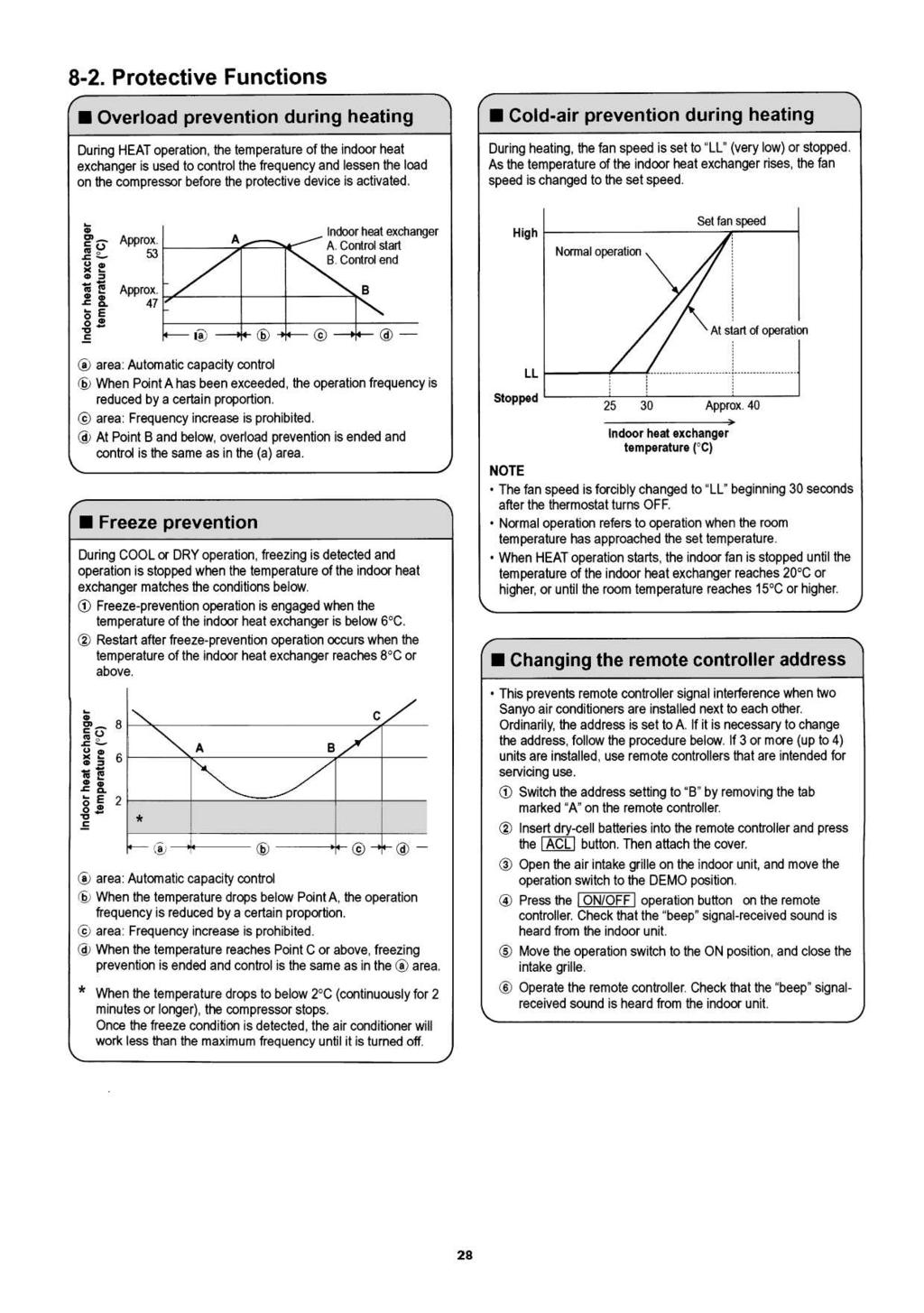
29 8. FUNCTIONS 8-1. Operation Functions Functions of the main unit controller 1 OFF : Used to stop the unit when the remote (Self-diagnostics) controller is unavailable. Used when service inspection is performed. 2 ON : During normal operation: Starts operation from the remote controller. Emergency operation: When the remote controller is unavailable, moving this switch from the OFF position to the ON position starts automatic operation. 3 TEST : Used when operating performance are checked. Used when pump-down is carried out. (Operates at the rated frequency. At this time, the main unit lamp flashes, and the remote controller signal cannot be received.) 4 DEMO : This function is for shop displays. Ordinarily it is not used. Used during servicing. Automatic operation Operating mode selection When automatic operation is selected, the indoor and outdoor temperature sensors function, and either HEAT, DRY, or COOL mode operation is selected automatically. Outdoor air temperature (Approx.) 22 C 20 C 18 C When multiple indoor units are connected and this unit is started while another indoor unit is operating, the operating mode is as shown in the table below. Operating mode before change HEAT COOL DRY Indoor temperature (Approx.) 15 C 22 C 27 C HEAT mode COOL DRY HEAT HEAT DRY mode Multi operating mode COOL mode Set temperature (standard) DRY DRY HEAT HEAT 27 C Temperature at which operation starts (Range: C) 24 C Operating mode after change If the remote controller is used to start automatic operation, a differing-mode check is performed if the operating modes are not the same. Desired-temperature memory The set temperature in the program can be changed as desired within the range of ±4 C. This temperature can then be stored. During automatic operation, press the temperature setting buttons to change the temperature. SENSOR DRY During automatic operation, the system adjusts the room temperature and fan speed according to the conditions in the room, in order to maintain a comfortable room environment. SENSOR DRY operation DRY operation is as shown in the figure below. Load DRY A The compressor operation frequency varies depending on the relative humidity. The indoor fan operates with 1/f fluctuation. DRY B The compressor operates at a low operating frequency. The indoor fan operates with 1/f fluctuation. Monitor COOL zone A zone B zone Conditions are monitored at all times when the room temperature is below 15 C. Monitoring operation takes place when the room temperature is below 15 C. When the monitoring range is entered, the compressor stops, and the indoor fan operates at LL. PAM-α control In order to further improve inverter performance, control is switched between PWM control at low operation speeds, and PAM control at high operation speeds, making the most effective use of power. 26
30 HIGH POWER Raises the power but remains in the same operating mode. This function is set with the HIGH POWER button on the remote controller. (It is set regardless of the temperature and fan speed settings.) HIGH POWER operation from the remote controller The unit operates at maximum output for 15 minutes, regardless of the desired temperature. The fan speed is 1 step above High. Frequency MAX 0 Start End NOTE When HIGH POWER operation ends, the unit operates at low Hz for 5 minutes, regardless of the thermostat OFF conditions. When in DRY mode, operation is in the cooling zone. When in HEAT mode, defrosting does not occur during HIGH POWER operation. If HIGH POWER is set while defrosting is in progress, HIGH POWER operation begins after defrosting ends. HIGH POWER operation cannot be set from the remote controller when the unit is stopped. HIGH POWER operation and ECONOMY operation cannot be used at the same time. The function set last takes priority. ECONOMY 15 min. 5 min. Time When ECONOMY operation is set, the temperature and fan speed settings will be adjusted automatically to allow comfortable sleep. When ECONOMY operation is set, mark appears on the remote controller. COOL and DRY modes The indoor unit fan speed is automatically lowered for quiet operation. The temperature setting is raised by 1 C one hour after ECONOMY operation is set. HEAT mode The indoor unit and outdoor unit fan speeds are automatically lowered for quiet operation. The temperature setting is lowered by 3 C one hour after ECONOMY operation is set. In addition, the temperature setting is lowered by 4 C after two hours have passed. Lamp colors Operation lamp HEAT operation : Red DRY operation : Orange COOL operation : Green TIMER lamp : Green ON timer operation Operation starts when the time set for the ON timer is reached. When a time is set, the TIMER lamp illuminates. The below comfort timer programming is performed. A comfort time is calculated from the set temperature and the room temperature, either 60 minutes prior or 30 minutes prior to the set ON timer time, and operation is started in advance of the set ON time. (The indoor fan speed is Medium. ) [COOL] Indoor temperature Set temperature = Temperature difference [HEAT] Set temperature Indoor temperature = Temperature difference Temperature difference ( C) NOTE This function does not operate if the ON timer standby time is less than 30 minutes. OFF timer operation Operation stops when the time set for the OFF timer is reached. When a time is set, the TIMER lamp illuminates. Timer backup Advance start time (min.) 12 < Temperature difference 60 6 < Temperature difference 30 If the indoor unit is unable to receive the timer time-end signal when the ON or OFF time is reached, then timer time-end occurs according to the indoor unit backup timer within approximately 26 minutes. Operation stops if there are no operator controls for 25 hours or longer after unit operation switched from OFF to ON by use of ON timer operation. 27
31
32 9. TROUBLESHOOTING Precautions before performing inspection or repair After checking the self-diagnostics monitor, turn the power OFF before starting inspection or repair. High-capacity electrolytic capacitors are used inside the outdoor unit controller (inverter). They retain an electrical charge (charging voltage DC 280 V) even after the power is turned OFF, and some time is required for the charge to dissipate. Be careful not to touch any electrified parts before the controller LED (red) turns OFF. If the outdoor controller is normal, approximately 30 seconds will be required for the charge to dissipate. However, allow at least 5 minutes for the charge to dissipate if there is thought to be any trouble with the outdoor controller. After inspection or repair is completed, be sure to move the operation switch to the DEMO position, turn the power ON, and erase the diagnostics contents. Method of self-diagnostics If the indoor unit operation lamp is flashing every 0.5 seconds, follow the procedure below to perform detailed trouble diagnostics. NOTE 1: If the operation lamp flashes every 0.5 seconds immediately when the power is turned ON, there is an external ROM (OTP data) failure on the indoor circuit board or ROM socket insertion problem, or the ROM has not been installed. 2: The failure mode is stored in memory even when the power is not ON. Follow the procedure below to perform diagnostics. DEMO TEST ON OFF Operation selector Ordinarily, this switch should be in the ON position. The OFF, TEST, and DEMO positions are used for inspection. PROCEDURE 1 Turn the power switch ON. 2 Move the operation selector on the main unit to OFF (self-diagnostics). 3 If there is a sensor failure or a protective function has activated, self-diagnostics lamps 1, 2, and 3 will illuminate in the following pattern: 5 seconds flashing (illuminated) + 2 seconds OFF. (Buzzer sounds once while lamps are OFF.) Note: If there is no trouble, then self-diagnostics lamps 1, 2, and 3 do not illuminate, and the buzzer does not sound. 4 Diagnostics is completed when the buzzer sounds 3 beeps. 5 After inspection or repair is completed, be sure to move the operation selector to the DEMO position, turn the power ON, and erase the diagnostics contents. Then move the selector to the OFF position and check that the diagnostics contents have been erased before using the unit. 29
33 Details of Self-Diagnostics When the operation selector on the indoor unit is moved from the ON or TEST position to the OFF (Self-diagnostics) position, the indicator lamps on the indoor unit will flash (or remain ON) for 5 seconds and then turn OFF for 2 seconds (buzzer sounds once) to indicate the presence of a sensor failure or the activation of a protective function. Self-diagnostics is completed when the buzzer sounds 3 beeps. If there is no trouble, the lamps do not flash (illuminate). Also note that the corresponding parts listed below may not be present in some models. Indication on indoor unit Timer Operation... OFF Code Diagnostics item Diagnostics contents S01 S02 Room temperature sensor failure Indoor heat exchanger sensor failure 1 Sensor open circuit or short circuit 2 Contact failure at connector or open circuit at terminal crimping location (short-circuit detection only for the humidity sensor) 3 Indoor/outdoor circuit board failure Humidity sensor failure S03... Flashing... ON S04 S05 S06 Compressor temperature sensor failure SH sensor failure Outdoor heat exchanger sensor failure Outdoor narrow tubing sensor failure Outdoor air temperature sensor failure Outdoor wide tubing sensor failure 1 Sensor open circuit or short circuit 2 Contact failure at connector or open circuit at terminal crimping location 3 Outdoor circuit board failure S07 E01 E02 E03 E04 E05 E06 E07 E08 E09 E10 E11 E12 E13 Outdoor electrical current sensor failure Indoor/outdoor communications failure (serial communications) HIC circuit failure Power Tr circuit failure Outdoor unit external ROM failure Peak current cut-off PAM circuit failure Active circuit failure Compressor discharge overheat prevention Indoor fan operating failure 4-way valve switching failure Indoor zero-cross failure No-refrigerant protection DC compressor drive circuit failure Outdoor AC fan operating failure Outdoor system communications failure Outdoor Hi-pressure SW, OLR operation Outdoor power supply open phase, outdoor coil freezing Freeze-prevention operation Outdoor circuit board failure 1 Miswiring 2 AC power failure 3 Blown fuse 4 Power relay failure 5 Indoor or outdoor circuit board failure 1 HIC or power Tr failure 2 Outdoor fan does not turn. 3 Instantaneous power outage 4 Service valve not opened. 5 Outdoor fan blocked. 6 Continuous overload operation 7 Compressor failure 8 Outdoor circuit board failure 1 External ROM data failure 2 Outdoor circuit board failure 1 Instantaneous power outage 2 HIC or power Tr failure 3 Outdoor circuit board failure 1 Outdoor circuit board failure 2 Outdoor power supply voltage failure 1 Electric expansion valve failure 2 Capillaries blocked. 3 No gas 4 Continuous overload operation 5 Outdoor fan does not turn. 6 Outdoor circuit board failure 1 Fan motor failure 2 Contact failure at connector 3 Indoor circuit board failure 1 4-way valve failure 2 Outdoor circuit board failure 1 Service valve not opened. 2 No refrigerant 1 Open phase 2 Outdoor circuit board failure 1 Fan motor failure 2 Contact failure at connector 3 Outdoor circuit board failure 1 Miswiring 2 Blown fuse 3 Power relay failure 4 Open phase 5 Outdoor circuit board failure 6 Compressor failure 1 Indoor fan system failure 2 No refrigerant 3 Low-temperature operation NOTE : If the operation lamp continues to flash (orange) even when the indoor unit operation selector has been moved to the OFF position, an indoor unit external ROM failure has occurred. (E14) After inspection or repair is completed, be sure to move the operation selector to the DEMO position, turn the power ON, and erase the diagnostics contents. 30
34 If the self-diagnostics function fails to operate Check the indoor unit. Is the fuse blown? Normal Replace the controller. No indicators illuminate and the indoor fan does not turn. Check the power voltage. Blown Replace the circuit board or the fuse. <Checking the indoor and outdoor units> Checking the indoor unit No. Control Check items (unit operation) 1 Set operation selector of indoor unit to The rated voltage must be present between inter-unit cables 1 and 2. DEMO and start operation using the remote Connect a 5 kω resistor between inter-unit cables 2 and 3. When the controller. voltage at both ends is measured, approximately V DC must be output and the needle must fluctuate once every 8 seconds. In addition, insert an LED jig and check that the LED flickers once every 8 seconds. If there are no problems with the above, then check the outdoor unit. Checking the outdoor unit No. Control Check items (unit operation) 1 Apply the rated voltage between outdoor The control panel LED (red) must illuminate. unit terminals 1 and 2. 2 Short-circuit the outdoor unit COM terminal The compressor and fan motor must turn ON. to the T-RUN terminal. If there are no problems with the above, then check the indoor unit. Using the TEST/T-RUN terminals T-RUN : Test run (compressor and fan motor turn ON.) TEST/MV : Compresses time to 1/60th (accelerates operation by 60 times faster than normal). Fully opens the electric expansion valve. TEST/T-RUN terminals TEST/MV T-RUN COM Checking the serial communications Initial selfdiagnostics Control 1 Short-circuit terminals 2 and 3 on the indoor unit 3P terminal block. Control 2 Short-circuit terminals 2 and 3 on the indoor unit 3P terminal block. Probable location of malfunction No change Indoor unit circuit board failure (1) illuminate Change: (1) and (3) illuminate, Change: (1) and (3) illuminate, Outdoor unit circuit board failure and (2) flashes. and (2) flashes. Change: (1) and (3) illuminate, Change: (1) illuminates Failure (open circuit, contact failure, etc.) and (3) flashes. in the inter-unit cable (1) and (3) illuminate, and (2) flashes. Indoor unit circuit board failure Turn the power OFF before performing short circuiting work. During the self-diagnostics check, the check results are the first indication when the operation switch is moved to OFF while the indicators are flashing after power ON DEMO (5 seconds) ON. So that the check can be made quickly, indicators flash at first communication after power ON. Before performing the above checks, perform DEMO operation, and check that AC 220 V is output to terminals 1 and 2. If it is not output, there is a failure related to the indoor unit power. 31
35 <Noise malfunction and electromagnetic interference> An inverter A/C operates using pulse signal control and high frequencies. Therefore, it is susceptible to the effects of external noise, and is likely to cause electromagnetic interference with nearby wireless devices. A noise filter is installed for ordinary use, preventing these problems. However, depending on the installation conditions, these effects may still occur. Please pay attention to the points listed below. Noise malfunction This refers to the application of high-frequency noise to the signal wires, resulting in abnormal signal pulses and malfunction. Locations most susceptible to noise 1. Locations near broadcast stations where there are strong electromagnetic waves 2. Locations near amateur radio (short wave) stations 3. Locations near electronic sewing machines and arc-welding machines Trouble Either of the following trouble may occur. 1. The unit may stop suddenly during operation. 2. Indicator lamps may flicker. Correction (The fundamental concept is to make the system less susceptible to noise.) Insulate for noise or distance from the noise source. 1. Use shielded wires. 2. Move unit away from the noise source. Electromagnetic interference This refers to the noise generated by high-speed switching of the microcomputer and compressor. This noise radiates through space and returns to electric wiring, affecting any wireless devices (televisions, radios, etc.) located nearby. Locations most susceptible to noise 1. A television or radio is located near the A/C and A/C wiring. 2. The antenna cable for a television or radio is located close to the A/C and A/C wiring. 3. Locations where television and radio signals are weak. Trouble 1. Noise appears in the television picture, or the picture is distorted. 2. Static occurs in the radio sound. Correction 1. Select a separate power source. 2. Keep the A/C and A/C wiring at least 1 meter away from wireless devices and antenna cables. 3. Change the wireless device's antenna to a highsensitivity antenna. 4. Change the antenna cable to a BS coaxial cable. 5. Use a noise filter (for the wireless device). 6. Use a signal booster. 32
36 APPENDIX INSTRUCTION MANUAL Wall Mounted Type Indoor Unit 33
37 Features This air conditioner is equipped with cooling, heating, and drying functions. Details on these functions are provided below; refer to these descriptions when using the air conditioner. Microprocessor Controlled Operation The interior compartment of the remote control unit contains several features to facilitate automatic operation, easy logically displayed for easy use. Simple One-touch Wireless Remote Control The remote control unit has several features to facilitate automatic operation. 24-Hour ON or OFF Timer This timer can be set to automatically turn the unit on or off at 10 minutes intervals within a 24 hour period. 1-Hour OFF Timer This timer can be set to automatically turn off the unit at any time after one hour. ECONOMY Mode Pressing this button changes the setting of the room temperature thermostat, allowing you to set the temperature at whatever level that you find comfortable. Automatic and 3-step Fan Speed Auto/High/Medium/Low Air Sweep Control This function moves a flap up and down in the air outlet, directing air in a sweeping motion around the room and providing comfort in every corner. High Power Cooling When a cooling or drying operation is to be performed, the air conditioner operates for 15 minutes in the high power mode. Odor Reduction Mode When a cooling or drying operation is to commence, the indoor fan motor is shut down for 40 seconds to minimize the odors which are produced when operation starts up. Mold Inhibiting Mode Upon completion of a cooling or drying operation, the indoor fan motor operates in the fan mode for 30 seconds to prevent condensation inside the indoor unit and inhibit the growth of mold. Anti-Mold Filter This unit is equipped with an anti-mold filter that inhibits the growth of mold and bacteria. Air Clean Filter An air filter that uses antibacterial filter to eliminate unpleasant odors and clean the air. 2 OI EG
38 Contents Page Features... 2 Product Information... 3 Alert Symbols... 3 Installation Location... 4 Electrical Requirements... 4 Safety Instructions... 4 Names of Parts... 5 Using the Remote Control Unit Operation with the Remote Control Unit Automatic Operation Manual Operation Adjusting the Fan Speed ECONOMY Mode Special Remarks Setting the Timer Setting the 1-Hour OFF Timer Setting the HIGH POWER Operation Tips for Energy Saving Adjusting the Airflow Direction Operation without the Remote Control Unit Care and Cleaning Troubleshooting Operating Range Product Information If you have problems or questions concerning your Air Conditioner, you will need the following information. Model and serial numbers are on the nameplate on the bottom of the cabinet. Model No. Serial No. Date of purchase Dealer s address Phone number DECLARATION OF CONFORMITY This product is marked as it satisfies EEC Directive No. 89/336/ EEC, 73/23/EEC and 93/68/EEC. This declaration will become void in case of mis-usage and/or from non observance though partial of Manufacturer s installation and/or operating instructions. Alert Symbols The following symbols used in this manual, alert you to potentially dangerous conditions to users, service personnel or the appliance: This symbol refers to a hazard or unsafe practice which can result in severe personal injury or death. CAUTION This symbol refers to a hazard or unsafe practice which can result in personal injury or product or property damage. OI EG 3
39 Installation Location We recommend that this air conditioner be installed properly by qualified installation technicians in accordance with the Installation Instructions provided with the unit. Before installation, check that the voltage of the electric supply in your home or office is the same as the voltage shown on the nameplate. Do not install this air conditioner where there are fumes or flammable gases, or in an extremely humid space such as a greenhouse. Do not install the air conditioner where excessively high heatgenerating objects are placed. Avoid: To protect the air conditioner from heavy corrosion, avoid installing the outdoor unit where salty sea water can splash directly onto it or in sulphurous air near a spa. Electrical Requirements 1. All wiring must conform to the local electrical codes. Consult your dealer or a qualified electrician for details. 2. Each unit must be properly grounded with a ground (or earth) wire or through the supply wiring. 3. Wiring must be done by a qualified electrician. Safety Instructions Read this Instruction Manual carefully before using this air conditioner. If you still have any difficulties or problems, consult your dealer for help. This air conditioner is designed to give you comfortable room conditions. Use this only for its intended purpose as described in this Instruction Manual. Never use or store gasoline or other flammable vapor or liquid near the air conditioner it is very dangerous. This air conditioner has no ventilator for intaking fresh air from outdoors. You must open doors or windows frequently when you use gas or oil heating appliances in the same room, which consume a lot of oxygen from the air. Otherwise there is a risk of suffocation in an extreme case. CAUTION Do not turn the air conditioner on and off from the power mains switch. Use the ON/OFF operation button. Do not stick anything into the air outlet of the outdoor unit. This is dangerous because the fan is rotating at high speed. Do not let children play with the air conditioner. Do not cool or heat the room too much if babies or invalids are present. 4 OI EG
40 Names of Parts Air intakes INDOOR UNIT Air outlet Remote control unit Drain hose Refrigerant tubes OUTDOOR UNIT Air outlet NOTE This illustration is based on the external view of a standard model. Consequently, the shape may differ from that of the air conditioner which you have selected. This air conditioner consists of an indoor unit and an outdoor unit. You can control the air conditioner with the remote control unit. Air Intake Air Outlet Remote Control Unit Refrigerant Tubes Drain Hose Outdoor (Condensing) Unit Air from the room is drawn into this section and passes through air filters which remove dust. Conditioned air is blown out of the air conditioner through the air outlet. The wireless remote control unit controls power ON/OFF, operation mode selection, temperature, fan speed, timer setting, and air sweeping. The indoor and outdoor units are connected by copper tubes through which refrigerant gas flows. Moisture in the room condenses and drains off through this hose. The outdoor unit contains the compressor, fan motor, heat exchanger coil, and other electrical components. OI EG 5
41 Unit Display and Operation Selector MCAF94/124/184MR5IAA INDOOR UNIT Operation selector MCAF244MR5IAA INDOOR UNIT Operation selector TIMER lamp OPERATION lamp SERVICE lamp TIMER lamp OPERATION lamp REMOTE CONTROL recelver IMPORTANT Avoid using radio equipment such as mobile phone near (within 1 m) the remote control receiver. Some radio equipment may cause malfunction of the unit. If the trouble happens, disconnect power and restart the air conditioner after a few minutes. REMOTE CONTROL receiver Operation selector ON position OFF position WARNING This section picks up infrared signals from the remote control unit (transmitter). This position is for operating the air conditioner with the wireless remote control unit. Set the selector normally in this position. Switch the selector to the OFF position if you are not going to use the air conditioner for a few days or longer. The OFF position does not disconnect the power. Use the main power switch to turn off power completely. TEST position CAUTION This position is used only when servicing the air conditioner. Do not set at the TEST position for normal operation. DEMO position OPERATION lamp TIMER lamp SERVICE lamp This position is used only when setting address of the remote control unit. This lamp lights when the system is in the continuous AUTO (red, orange or green), HEAT (red), DRY (orange) and COOL (green) mode. This lamp lights when the system is being controlled by the timer. When a fault occurs in the air conditioner, this lamp turns on or flashes in combination with the other two lamps to indicate the type of fault. 6 OI EG
42 Remote Control Unit (Display) Displayed when setting temperature in automatic operation Displayed when transmitting data Displayed when indoor unit sensor is in use Displayed when setting timer Displayed when setting temperature Symbols (1) Operation mode AUTO... HEAT... (5) ECONOMY... (6) High power operation... (7) Flap indication DOUBLE SENSOR DRY... Auto. flap indication... COOL... Flap angle indication... (2) Confirmation of transmission... (3) Set temperature C When set to 28 C... (4) Timer Current temperature indication... ON Timer... Sweep indication... (8) Fan speed Automatic operation... HIGH... MEDIUM... OFF Timer... LOW... 1-hour OFF Timer... OI EG 7
43 Remote Control Unit Sensor Transmitter Display (Cover closed) HIGH POWER button 1 HR. TIMER button OFF TIME setting button ON TIME setting button Return button Advance button SET button CANCEL button CLOCK button ON/OFF operation button Temperature setting buttons (TEMP.) ECONOMY button MODE selector button FAN SPEED selector button FLAP button A/C SENSOR button ADDRESS switch Battery compartment (Pull off the cover to expose the batteries.) ACL button Model No.: RCS-3MVHPS4E NOTE The illustration above pictures the remote control unit after the cover has been lowered and removed. Transmitter When you press the buttons on the remote control unit, the mark appears in the display to transmit the setting changes to the receiver in the air conditioner. Sensor A temperature sensor inside the remote control unit senses the room temperature. Display Information on the operating conditions is displayed while the remote control unit is switched on. If the unit is turned off, only the mode that was set previously is still displayed. HIGH POWER button : When you press this button, the current operation mode is set to the HIGH POWER mode, and the unit is operated in this mode for 15 minutes. ON/OFF operation button This button is for turning the air conditioner on and off. 1 HR. TIMER button (1-HOUR OFF TIMER) Temperature setting buttons (TEMP.) : When you press this button, regardless of whether the unit is operating or stopping, the unit operates for one hour and then shuts down. Press the button to increase the set temperature. Press the button to reduce the set temperature. For details, see Automatic operation and Manual operation. 8 OI EG
TECHNICAL DATA & SERVICE MANUAL
 TECHNICAL DATA & SERVICE MANUAL INDOOR UNIT: CAF97R5IAA CAF98MR5IAA CAF127R5IAA CAF128MR5IAA CAF187R5IAA SPLIT SYSTEM AIR CONDITIONER Model No. CAF97R5IAA CAF127R5IAA CAF187R5IAA CAF98MR5IAA CAF128MR5IAA
DC INVERTER MULTI-SYSTEM AIR CONDITIONER
 AIR CONDITIONER AIR CONDITIONER TECHNICAL & SERVICE MANUAL INDOOR UNIT : KMS0772 FILE NO. KMS0972 KMS1272 KMS1872 KMS2472 Destination: North America DC INVERTER MULTI-SYSTEM AIR CONDITIONER Capacity 7,500BTU
DC INVERTER SPLIT SYSTEM AIR CONDITIONER
 AIR CONDITIONER TECHNICAL & SERVICE MANUAL KS1872 + C1872 + CL1872 KS2472 + C2472 + CL2472 FILE NO. Destination: North America DC INVERTER SPLIT SYSTEM AIR CONDITIONER Indoor Model No. KS1872 KS2472 Product
TECHNICAL DATA & SERVICE MANUAL SPLIT SYSTEM AIR CONDITIONER INDOOR UNIT: AW22AL AW28AL AW38AL AW42AL AW22AL AW28AL AW38AL
 TECHNICAL DATA & SERVICE MANUAL INDOOR UNIT: AW22AL AW28AL AW38AL AW42AL SPLIT SYSTEM AIR CONDITIONER Model No. Product Code No. AW22AL 387030005 AW28AL 387030006 AW38AL 387030007 AW42AL 387030094 0.8180.467.0
TECHNICAL DATA & SERVICE MANUAL
 TECHNICAL DATA & SERVICE MANUAL OUTDOOR UNIT:. TRIAL SPLIT SYSTEM AIR CONDITIONER Model No. Product Code No. 38.7107.102. 0.8180.611.02 09/2012 IMPORTANT! Please read before installation This air conditioning
DC INVERTER MULTI-SYSTEM AIR CONDITIONER Capacity 7,500BTU / h 9,000BTU / h 11,900BTU / h 17,500BTU / h 24,200BTU / h
 AIR CONDITIONER AIR CONDITIONER TECHNICAL & SERVICE MANUAL INDOOR UNIT : CS-MKS7NKU CS-MKS9NKU CS-MKS12NKU CS-MKS18NKU CS-MKS24NKU DC INVERTER MULTI-SYSTEM AIR CONDITIONER Capacity 7,500BTU / h 9,000BTU
DC INVERTER MULTI-SYSTEM AIR CONDITIONER
 TECHNICAL & SERVICE MANUAL OUTDOOR UNIT : CLM97 CLM7 CLM7 FILE NO. Destination: North America DC INVERTER MULTI-SYSTEM AIR CONDITIONER Capacity at 0V 9,700 BTU/h,00 BTU/h 0,600 BTU/h Outdoor Model No.
TECHNICAL DATA & SERVICE MANUAL
 TECHNICAL DATA & SERVICE MANUAL OUTDOOR UNIT: GRF188R5TAA GRF228R5TAA GRF228R7TAA SPLIT SYSTEM AIR CONDITIONER Model No. Product Code No. GRF188R5TAA 38.7107.083 GRF228R5TAA 38.7107.084 GRF228R7TAA 38.7107.085
DC INVERTER MULTI-SYSTEM AIR CONDITIONER
 AIR CONDITIONER AIR CONDITIONER TECHNICAL & SERVICE MANUAL INDOOR UNIT : MCAF78MR5I MCAF98MR5I MCAF128MR5I MCAF188R5I MCAF248R5I FILE NO. Destination: Europe DC INVERTER MULTI-SYSTEM AIR CONDITIONER Capacity
TECHNICAL DATA & SERVICE MANUAL SPLIT SYSTEM AIR CONDITIONER INDOOR UNIT: ASR609CL ASR612CL ASR609CL ASR612CL
 TECHNICAL DATA & SERVICE MANUAL INDOOR UNIT: ASR609CL ASR612CL SPLIT SYSTEM AIR CONDITIONER Model No. Product Code No. ASR609CL 387006970 ASR612CL 387006971 0.8180.250.0 05/2002 IMPORTANT! Please read
TECHNICAL & SERVICE MANUAL SPLIT SYSTEM AIR CONDITIONER
 TECHNICAL & SERVICE MANUAL SAP K161GJA SAP K181GJA SAP K181MBA SAP K241GJA SAP K241MBA + SAP C161GA + SAP C161JA + SAP C181GA + SAP C181JA + SAP C181MA + SAP C181BA + SAP C241GA + SAP C241JA + SAP C241MA
TECHNICAL DATA & SERVICE MANUAL
 TECHNICAL DATA & SERVICE MANUAL OUTDOOR UNIT: AE726SCL AE752SCL AE71SCL3 AE735SCL AE752SCL3 AE100SCL3 AE764SCL3 AE125SCL3 SPLIT SYSTEM AIR CONDITIONER Model No. AE726SCL AE735SCL AE752SCL AE752SCL3 AE764SCL3
TECHNICAL DATA & SERVICE MANUAL SPLIT SYSTEM AIR CONDITIONER INDOOR UNIT: CAF94R5 CAF124R5 CAF94R
 TECHNICAL DATA & SERVICE MANUAL INDOOR UNIT: CAF94R5 CAF124R5 SPLIT SYSTEM AIR CONDITIONER Model No. Product Code No. CAF94R5 387106979 CAF124R5 387106980 0.8180.361.0 07/2005 IMPORTANT! Please read before
DC INVERTER SPLIT SYSTEM AIR CONDITIONER
 AIR CONDITIONER TECHNICAL & SERVICE MANUAL MCAF94R5IAA + GRF97R5I MCAF124R5IAA + GRF127R5I FILE NO. Destination: Europe DC INVERTER SPLIT SYSTEM AIR CONDITIONER Indoor Model No. Product Code No. MCAF94R5IAA
TECHNICAL DATA & SERVICE MANUAL SPLIT SYSTEM AIR CONDITIONER OUTDOOR UNIT: AE22AC/ACL/AH AE28AC/ACL/AH AE38AC/ACL/AH AE42AC/ACL/AH
 TECHNICAL DATA & SERVICE MANUAL OUTDOOR UNIT: AE22AC/ACL/AH AE28AC/ACL/AH AE38AC/ACL/AH AE42AC/ACL/AH SPLIT SYSTEM AIR CONDITIONER Model No. Product Code No. AE22AH 387031006 AE28AH 387031007 AE38AH 387031008
TECHNICAL DATA & SERVICE MANUAL
 TECHNICAL DATA & SERVICE MANUAL OUTDOOR UNIT: DUAL SPLIT SYSTEM AIR CONDITIONER Model No. Product Code No. 38.7107.098 38.7107.103 38.7107.106 0.8180.597.03 09/2012 IMPORTANT! Please read before installation
DC INVERTER MULTI-SYSTEM AIR CONDITIONER
 TECHNICAL & SERVICE MANUAL INDOOR UNIT : CS-MKE9NB4U & CZ-18BT1U CS-MKE12NB4U & CZ-18BT1U CS-KE18NB4UW & CZ-18BT1U DC INVERTER MULTI-SYSTEM AIR CONDITIONER Capacity 9,000BTU / h 11,900BTU / h 17,500BTU
7-5. Remove the Grille to Install the Indoor Unit
 7-5. Remove the Grille to Install the Indoor Unit Basically, these models can be installed and wired without removing the grille. If access to any internal part is needed, follow the steps as given below.
TECHNICAL DATA & SERVICE MANUAL
 TECHNICAL DATA & SERVICE MANUAL HEAT PUMP MODELS INDOOR UNIT: MPAF188R5TAA MPAF228R5TAA COOLING MODELS MPAF188C5TAA MPAF228C5TAA SPLIT SYSTEM AIR CONDITIONER Model No. Product Code No. MPAF188R5TAA 38.7104.033
DC INVERTER MULTI-SYSTEM AIR CONDITIONER
 TECHNICAL & SERVICE MANUAL INDOOR UNIT : MPAF90MRI MPAF0MRI MPAF80RI MPAF0RI DC INVERTER MULTISYSTEM AIR CONDITIONER Capacity Indoor Model No..6 kw.0 kw. kw 7.0 kw MPAF90MRI MPAF0MRI MPAF80RI MPAF0RI Wall
SPLIT SYSTEM AIR CONDITIONER
 TECHNICAL DATA & SERVICE MANUAL INDOOR UNIT: MRAF99R5IAA MRAF129R5IAA MPAF99R5IAA MPAF129R5IAA SPLIT SYSTEM AIR CONDITIONER Model No. Product Code No. MRAF99R5IAA 38.7104.065 MRAF129R5IAA 38.7104.062 MPAF99R5IAA
TECHNICAL DATA & SERVICE MANUAL
 TECHNICAL DATA & SERVICE MANUAL XH7R / CH7R, C7R XH7R / CH7R, C7R XH7R / CH7R, C7R TH7R / CH7R, C7R TH7R / CH7R, C7R TH7R / CH7R, C7R THH7R / CH7R THH7R / CH7R FILE NO. KH7R / CH7R, C7R KH07R / CH07R,
TECHNICAL & SERVICE MANUAL SAP K181A + SAP C181A
 TECHNICAL & SERVICE MANUAL SAP K181A SAP K241A + SAP C181A + SAP C241A FILE NO. Destination: Australia SPLIT SYSTEM AIR CONDITIONER Indoor Model No. Product Code No. SAP K181A S 1 852 068 06 SAP K241A
INSTALLATION INSTRUCTIONS
 INSTALLATION INSTRUCTIONS - Wall-mount indoor unit - OPERATING LIMITS Cooling Maximum conditions Heating Maximum conditions Outdoor temperature : 122 F (50 C) D.B. Outdoor temperature : 75 F (24 C) D.B.
DC INVERTER SPLIT SYSTEM AIR CONDITIONER
 AIR CONDITIONER TECHNICAL & SERVICE MANUAL MCAF88R5I + GRF86R5I MCAF48R5I + GRF46R5I FILE NO. Destination: Europe DC INVERTER SPLIT SYSTEM AIR CONDITIONER Indoor Model No. Product Code No. MCAF88R5I MCAF88R5IAA
DC INVERTER SPLIT SYSTEM AIR CONDITIONER
 AIR CONDITIONER TECHNICAL & SERVICE MANUAL KS0971 + C0971 + CL0971 KS1271 + C1271 + CL1271 FILE NO. Destination: North America DC INVERTER SPLIT SYSTEM AIR CONDITIONER Indoor Model No. KS0971 KS1271 Product
TECHNICAL & SERVICE MANUAL SPLIT SYSTEM AIR CONDITIONER SAP K301AH + SAP C301AH FILE NO. SAP K301AH SAP C301AH REFERENCE NO.
 TECHNICAL & SERVICE MANUAL SAP K301AH + SAP C301AH FILE NO. Destination: Australia SPLIT SYSTEM AIR CONDITIONER Indoor Model No. Product Code No. SAP K301AH S 1 852 071 34 Outdoor Model No. Product Code
DC INVERTER SPLIT SYSTEM AIR CONDITIONER
 TECHNICAL & SERVICE MANUAL XHS1271 & PNR-XS1872 + CH1271 XHS1872 & PNR-XS1872 + CH1872 FILE NO. Destination: North America DC INVERTER SPLIT SYSTEM AIR CONDITIONER Indoor Model No. Body (Panel) XHS1271
TECHNICAL & SERVICE MANUAL SPLIT SYSTEM AIR CONDITIONER SAP K303A + SAP C303A FILE NO. REFERENCE NO. SM Destination: Australia
 AIR CONDITIONER TECHNICAL & SERVICE MANUAL SAP K303A + SAP C303A FILE NO. Destination: Australia SPLIT SYSTEM AIR CONDITIONER Indoor Model No. Product Code No. SAP K303A A 1 852 098 83 Outdoor Model No.
Features. Simple One-touch Wireless Remote Control The remote control unit has several features to facilitate automatic operation.
 01_KMS1872_En.fm Page 2 Monday, November 14, 2005 1:28 PM Features This air conditioner is an inverter type unit that automatically adjusts capacity as appropriate. Details on these functions are provided
TECHNICAL DATA & SERVICE MANUAL MTF94C5TAA
 TECHNICAL DATA & SERVICE MANUAL MTF94C5TAA 0.8180.472.0 07/2005 Page 1. SPECIFICATIONS 3 1-1 Unit Specifications 3 1-2 Major Component Specifications 4 2. DIMENSIONAL DATA 6 2-1 Unit Dimensions 6 3. ELECTRICAL
TECHNICAL & SERVICE MANUAL WIRED REMOTE CONTROLLER STK-RCS-7TWSUA FILE NO. Product Code No Model No. STK-RCS-7TWSUA
 TECHNICAL & SERVICE MANUAL STK-RCS-7TWSUA FILE NO. Destination: North America WIRED REMOTE CONTROLLER Model No. STK-RCS-7TWSUA Product Code No. 1 852 353 85 REFERENCE NO. SM700799 Important! Please Read
XS1271 XS1872 INSTRUCTION MANUAL MODE D EMPLOI This air conditioner uses the new refrigerant R410A.
 XS1271 XS1872 COOL/DRY Model INSTRUCTION MANUAL Inverter-Controlled Split System Air Conditioner MODE D EMPLOI Climatiseur de type séparé contrôlé par inverseur This air conditioner uses the new refrigerant
DC INVERTER SPLIT SYSTEM AIR CONDITIONER
 TECHNICAL & SERVICE MANUAL XS171 & PNRXS187 + C171 XS171 & PNRXS187 + CL171 XS187 & PNRXS187 + CH187 XS187 & PNRXS187 + CL187 FILE NO. Destination: North America DC INVERTER SPLIT SYSTEM AIR CONDITIONER
DC INVERTER SPLIT SYSTEM AIR CONDITIONER
 AIR CONDITIONER TECHNICAL & SERVICE MANUAL CS-KS30NKU + CU-KS30NKUA CS-KS36NKU + CU-KS36NKUA DC INVERTER SPLIT SYSTEM AIR CONDITIONER Indoor Model No. CS-KS30NKU CS-KS36NKU Product Code No. 852 360 86
KMHS1872 KMHS2472 INSTRUCTION MANUAL MODE D EMPLOI. COOL/DRY/HEAT Model. Save These Instructions! Conserver ce mode d emploi
 INSTRUCTION MANUAL MODE D EMPLOI Inverter-Controlled Split System Air Conditioner Climatiseur de type séparé contrôlé par inverseur KMHS1872 KMHS2472 This air conditioner uses the new refrigerant R410A.
TECHNICAL & SERVICE MANUAL WINDOW TYPE AIR CONDITIONER SA 128S5 FILE NO. SA 128S5 REFERENCE NO. SM700338
 TECHNICAL & SERVICE MANUAL SA 128S5 FILE NO. WINDOW TYPE AIR CONDITIONER Model No. Product Code No. Destination SA-128S5-A 1 851 004 09 General (50Hz) & Europe SA 128S5 REFERENCE NO. SM700338 IMPORTANT!
TECHNICAL & SERVICE MANUAL WINDOW TYPE AIR CONDITIONER SA 123A FILE NO. SA 123A REFERENCE NO. SM700513
 TECHNICAL & SERVICE MANUAL SA 123A FILE NO. WINDOW TYPE AIR CONDITIONER Model No. Product Code No. Destination SA-123A 1 851 006 95 Australia SA 123A REFERENCE NO. SM700513 IMPORTANT! Please Read Before
TECHNICAL & SERVICE MANUAL WINDOW TYPE AIR CONDITIONER SA 183A FILE NO. SA 183A REFERENCE NO. SM Destination Australia SA-183A
 TECHNICAL & SERVICE MANUAL SA 183A FILE NO. WINDOW TYPE AIR CONDITIONER Model No. Product Code No. SA-183A 1 851 006 96 Destination Australia SA 183A REFERENCE NO. SM700514 IMPORTANT! Please Read Before
INVERTER SPLIT SYSTEM AIR CONDITIONER
 TECHNICAL & SERVICE MANUAL SAP-KRV91EH + SAP-CRV91EH FILE NO. INVERTER SPLIT SYSTEM AIR CONDITIONER Indoor Model No. Product Code No. Outdoor Model No. Product Code No. Destination SAP-KRV91EH 1 852 065
XHS1271 XHS1872. This air conditioner uses the new refrigerant R410A. COOL/DRY/HEAT Model
 XHS1271 XHS1872 COOL/DRY/HEAT Model INSTRUCTION MANUAL Inverter-Controlled Split System Air Conditioner MODE D EMPLOI Climatiseur de type séparé contrôlé par inverseur This air conditioner uses the new
TECHNICAL DATA & SERVICE MANUAL MULTI-SPLIT SYSTEM AIR CONDITIONER
 TECHNICAL DATA & SERVICE MANUAL Outdoor Unit GR54M2C Indoor Unit MCA27MC (X2) MULTI-SPLIT SYSTEM AIR CONDITIONER Indoor Unit Outdoor Unit MCA27MC GR54M2C 0.8180.195.0 04/2001 IMPORTANT! Please Read Before
TECHNICAL DATA & SERVICE MANUAL DISEGNO MACCHINA
 TECHNICAL DATA & SERVICE MANUAL DISEGNO MACCHINA ARGO 245C / 3SC Cooling only model ARGO 235H / 3HP Heat pump model 0.8180.405.2 09/2006 Table of contents Page A SPECIFICATIONS 1) Unit specifications 3
DC INVERTER SPLIT SYSTEM AIR CONDITIONER
 TECHNICAL & SERVICE MANUAL KHS308 + CH308 KHS368 + CH368 FILE NO. Destination: North America DC INVERTER SPLIT SYSTEM AIR CONDITIONER Indoor Model No. KHS308 KHS368 Product Code No. 85 354 8 85 354 9 Outdoor
DC INVERTER SPLIT SYSTEM AIR CONDITIONER
 AIR CONDITIONER TECHNICAL & SERVICE MANUAL CS-KE30NKU + CU-KE30NKU CS-KE36NKU + CU-KE36NKU DC INVERTER SPLIT SYSTEM AIR CONDITIONER Indoor Model No. CS-KE30NKU CS-KE36NKU Product Code No. 1 852 360 88
TECHNICAL DATA & SERVICE MANUAL SPLIT SYSTEM AIR CONDITIONER INDOOR UNIT: MCAF72R5TA- MCAF92R5TA- MCAF122R5TA-
 TECHNICAL DATA & SERVICE MANUAL INDOOR UNIT: MCAF72R5TA- MCAF92R5TA- MCAF122R5TA- SPLIT SYSTEM AIR CONDITIONER Model No. Product Code No. MCAF72R5TA- 387104015 MCAF92R5TA- 387104016 MCAF122R5TA- 387104017
IU-PSINV-HW12R IU-PSINV-HW16R IU-PSINV-HW18R IU-PSINV-HW25R
 OI825001_Airwell-PAC-i_COVER.fm Page 2 Thursday, July 2, 2009 3:52 PM Save These Instructions! Conserver ce mode d emploi Bewahren Sie bitte diese Bedienungsanleitung auf. Conservate queste istruzioni
TECHNICAL & SERVICE MANUAL WINDOW TYPE AIR CONDITIONER SA 93AH FILE NO. SA 93AH REFERENCE NO. SM700510
 TECHNICAL & SERVICE MANUAL SA 93AH FILE NO. WINDOW TYPE AIR CONDITIONER Model No. Product Code No. Destination SA-93AH 1 851 006 97 Australia SA 93AH REFERENCE NO. SM700510 IMPORTANT! Please Read Before
Operating Instructions Air Conditioner
 Operating Instructions Air Conditioner Model No. OUTDOOR UNIT Single Split (Single-phase) Type PZ2 U-100PZ2R5 U-125PZ2R5 U-140PZ2R5 Single Split (3-phase) Type PZ2 U-100PZ2R8 U-125PZ2R8 U-140PZ2R8 Connectable
TECHNICAL & SERVICE MANUAL SPLIT SYSTEM AIR CONDITIONER
 TECHNICAL & SERVICE MANUAL AWR222CLE - AER222SC AWR222CLE - AER222SC3 SPLIT SYSTEM AIR CONDITIONER 0.8180.076.0 03/00 Important! Please Read Before Starting This air conditioning system meets strict safety
DC INVERTER SPLIT SYSTEM AIR CONDITIONER
 TECHNICAL & SERVICE MANUAL XHS7 & PNRXS87 + CH7 XHS87 & PNRXS87 + CH87 FILE NO. Destination: North America DC INVERTER SPLIT SYSTEM AIR CONDITIONER Indoor Model No. Body (Panel) XHS7 (PNRXS87) XHS87 (PNRXS87)
DC INVERTER MULTI-SYSTEM AIR CONDITIONER
 TECHNICAL & SERVICE MANUAL OUTDOOR UNIT : CU-3KE19NBU CU-4KE24NBU CU-4KE31NBU DC INVERTER MULTI-SYSTEM AIR CONDITIONER Capacity at 0V 19,100 BTU/h,200 BTU/h 30,600 BTU/h Outdoor Model No. CU-3KE19NBU CU-4KE24NBU
INSTALLATION INSTRUCTIONS
 05-355 KMS0772_indoor 3/16/06 5:27 PM Page a INSTALLATION INSTRUCTIONS Inverter Split System Air Conditioner COOL/ DRY Model This air conditioner uses the new refrigerant R410A. For Indoor Unit Contents
Using the Remote Control Unit
 Remote Control Unit (continued) SENSOR button Temperature Display Selector button Time Display Selector button ACL button (ALL CLEAR) When you press this button (use a small-tipped object such as a ballpoint
SPLIT SYSTEM AIR CONDITIONER
 TECHNICAL DATA & SERVICE MANUAL INDOOR UNIT: MPAFIA0R5IAA SPLIT SYSTEM AIR CONDITIONER Model No. Product Code No. MPAFIA0R5IAA 38.7104.074 0.8180.590.01 10/2012 IMPORTANT! Please read before installation
MULTI-SPLIT SYSTEM AIR CONDITIONER
 TECHNICAL & SERVICE MANUAL SAP KM97AHA ( 2) + SAP CM1827AHA FILE NO. Destination: Australia MULTI-SPLIT SYSTEM AIR CDITIER Indoor Model No Product Code No. Outdoor Model No. Product Code No. SAP KM97AHA
DC INVERTER MULTI-SYSTEM AIR CONDITIONER
 TECHNICAL & SERVICE MANUAL OUTDOOR UNIT : SAP-CMRVEH FILE NO. Destination: Europe DC INVERTER MULTI-SYSTEM AIR CONDITIONER Capacity 0.0kW Outdoor Model No. SAP-CMRVEH-F Product Code No. 8 8 SAP-CMRVEH
INSTALLATION INSTRUCTIONS
 INSTALLATION INSTRUCTIONS Solenoid Valve Kit For 3WAY VRF System CZ-PXXXHR3 () IMPORTANT! Please Read Before Starting This solenoid Valve kit must be installed by the sales dealer or installer. This information
SPLIT TYPE ROOM AIR CONDITIONER. WALL MOUNTEDtype INVERTER. Models Indoor unit Outdoor unit AOU 9RLFW1 AOU12RLFW1 ASU 9RLF1 ASU12RLF1 R410A
 SERVICE INSTRUCTION SPLIT TYPE ROOM AIR CONDITIONER WALL MOUNTEDtype INVERTER Models Indoor unit Outdoor unit ASU 9RLF ASURLF AOU 9RLFW AOURLFW R40A CONTENTS. DESCRIPTION OF EACH CONTROL OPERATION. COOLING
Part 3 Troubleshooting
 Part Troubleshooting What is in this part? This part contains the following chapters: Chapter See page Troubleshooting 2 Error Codes: Hydro-box 7 Error Codes: Outdoor Units Error Codes: System Malfunctions
TECHNICAL DATA & SERVICE MANUAL DISEGNO MACCHINA
 TECHNICAL DATA & SERVICE MANUAL DISEGNO MACCHINA ARGO 245SCH2O( I ) Cooling only model ARGO 235HPH2O( I ) Heat pump model 0.8180.519.1 11 / 2007 Table of contents Page A SPECIFICATIONS 1) Unit specifications
This air conditioner uses the new refrigerant R410A.
 COP-INVERTER-ARGO.qxd 6-02-2004 16:07 Pagina 1 OPERATING INSTRUCTIONS NOTICE D UTILISATION BEDIENUNGSANLEITUNG ISTRUZIONI D USO INSTRUCCIONES DE USO This air conditioner uses the new refrigerant R410A.
R410A. WALL MOUNTEDtype INVERTER SPLIT TYPE ROOM AIR CONDITIONER. Models Indoor unit Outdoor unit AOYG07LEC AOYG09LEC AOYG12LEC AOYG14LEC
 SERVICE INSTRUCTION SPLIT TYPE ROOM AIR CONDITIONER WALL MOUNTEDtype INVERTER Models Indoor unit Outdoor unit ASYG07LECA ASYG09LECA ASYG12LECA ASYG14LECA AOYG07LEC AOYG09LEC AOYG12LEC AOYG14LEC R410A CONTENTS
OWNER S MANUAL. R 410A Ductless Split System Air Conditioner and Heat Pump
 R 410A Ductless Split System Air Conditioner and Heat Pump Models DLC4(A/H) Outdoor Unit, DLF4(A/H) Indoor Unit Sizes 9K, 12K, 18K, 24K, 30K and 36K Please read the operating instructions and safety precautions
R410A. WALL MOUNTEDtype INVERTER SPLIT TYPE ROOM AIR CONDITIONER. Models Indoor unit Outdoor unit AO*G09LTCN AO*G12LTCN AO*G14LTCN
 SERVICE INSTRUCTION SPLIT TYPE ROOM AIR CONDITIONER WALL MOUNTEDtype INVERTER Models Indoor unit Outdoor unit AS*G09LTCB AS*GLTCB AS*G4LTCB AO*G09LTCN AO*GLTCN AO*G4LTCN R40A CONTENTS. DESCRIPTION OF EACH
SERVICE INSTRUCTION R410A. WALL MOUNTEDtype SPLIT TYPE ROOM AIR CONDITIONER INVERTER. Models Indoor unit Outdoor unit AO* R09LECN AO* R12LECN
 SERVICE INSTRUCTION SPLIT TYPE ROOM AIR CONDITIONER WALL MOUNTEDtype INVERTER Models Indoor unit Outdoor unit AS* A09LEC AS* A12LEC AO* R09LECN AO* R12LECN R410A CONTENTS 1. DESCRIPTION OF EACH CONTROL
SERVICE INSTRUCTION R410A. WALL MOUNTEDtype INVERTER SPLIT TYPE ROOM AIR CONDITIONER. Models Indoor unit Outdoor unit AOU9RLS2H AOU12RLS2H AOU15RLS2H
 SERVICE INSTRUCTION SPLIT TYPE ROOM AIR CONDITIONER WALL MOUNTEDtype INVERTER Models Indoor unit Outdoor unit ASU9RLS ASURLS ASU5RLS AOU9RLSH AOURLSH AOU5RLSH R40A CONTENTS. DESCRIPTION OF EACH CONTROL
Installation Instructions
 40MBFQ Floor Console Ductless System Sizes 09 to 58 Installation Instructions TABLE OF CONTENTS PAGE SAFETY CONSIDERATIONS... 2 PARTS LIST... 3 SYSTEM REQUIREMENTS... 4 WIRING... 4 DIMENSIONS... 5 CLEARANCES...
INVERTER ONE-TWO/ONE-THREE/ONE-FOUR/ONE-FIVE SPLIT-TYPE AIR CONDITIONER
 INVERTER ONE-TWO/ONE-THREE/ONE-FOUR/ONE-FIVE SPLIT-TYPE AIR CONDITIONER Owner s Manual Model: 3554190/3554191/3554192/3554193 3554194/3554195/3554196/3554197 IMPORTANT NOTE: Read this manual carefully
Room Air Conditioner CONTENTS CS-E9BKP CU-E9BKP5 CS-E12BKP CU-E12BKP5. Order No: MAC C2
 Order No: MAC008C Room Air Conditioner CS-E9BKP CU-E9BKP5 CS-EBKP CU-EBKP5 CONTENTS Page Page Features Functions Product Specifications 6 Dimensions 0 5 Refrigeration Cycle Diagram 6 Block Diagram 7 Wiring
Operating Instructions Air Conditioner
 Operating Instructions Air Conditioner Low Silhouette Ducted (Type F1) INDOOR UNIT Low Silhouette Ducted (Type F1) S-60PF1R5A S-71PF1R5A S-100PF1R5A S-125PF1R5A S-140PF1R5A OUTDOOR UNIT Single Split (Single-phase)
YC ON-OFF SERIES. Service Manual
 YC ON-OFF SERIES Service Manual CONTENTS 1. Precaution... 3 1.1 Safety Precaution... 3 1.2 Warning... 3 2. Model Lists... 6 3. Dimension... 7 3.1 Indoor Unit... 7 3.2 Outdoor Unit... 11 4. Refrigerant
Owner s Manual Super-Slim Four-Way Cassette
 CASSETTE- TYPE AIR CONDITIONER Owner s Manual Super-Slim Four-Way Cassette IMPORTANT NOTE: Read this manual carefully before installing or operating your new air conditioning unit. Make sure to save this
Owner s Manual. Middle Static Pressure Duct Type MEU-18MPH2 MEU-24MPH2 MEU-36MPL2 MEU-48MPL2 MIDDLE STATIC PRESSURE DUCT TYPE AIR CONDITIONER
 MIDDLE STATIC PRESSURE DUCT TYPE AIR CONDITIONER Owner s Manual Middle Static Pressure Duct Type MEU-18MPH2 MEU-24MPH2 MEU-36MPL2 MEU-48MPL2 IMPORTANT NOTE: Read this manual carefully before installing
AUTO COOL DRY FAN SPEED AIR SWING OFF ON TIMER TIMER OFF/ON FAN SPEED MODE TEMP AIR SWING TIMER ON SET OFF CANCEL AC RC SET CHECK CLOCK RESET
 AUTO COOL DRY MODE TIMER ON OFF TIMER OFF/ON TEMP ON TIMER FAN SPEED AIR SWING SET 1 2 3 FAN SPEED AIR SWING OFF CANCEL AC RC SET CHECK CLOCK RESET Order No: PAPAMY1611008CE Indoor Unit CS-MPS9SKH CS-MPS12SKH
INVERTER WALL MOUNTED TYPE ROOM AIR-CONDITIONER (Split system, air to air heat pump type)
") TECHNICAL MANUAL & PARTS LIST DRAFT INVERTER WALL MOUNTED TYPE ROOM AIR-CONDITIONER (Split system, air to air heat pump type) SRK20ZD-S - 1 - INDOOR UNIT Model SRK20ZD-S OUTDOOR UNIT Model SRC20ZD-S REMOTE
TECHNICAL MANUAL & PARTS LIST DRAFT INVERTER WALL MOUNTED TYPE ROOM AIR-CONDITIONER (Split system, air to air heat pump type) SRK20ZD-S - 1 - INDOOR UNIT Model SRK20ZD-S OUTDOOR UNIT Model SRC20ZD-S REMOTE
KSD-35 DR11 KUE-35 DVN11
 FLOOR-STANDING TYPE AIR CONDITIONER Owner s Manual Floor-Standing Type KSD-35 DR11 KUE-35 DVN11 IMPORTANT NOTE: Read this manual carefully before installing or operating your new air conditioning unit.
OWNER S MANUAL. High-Wall Fan Coil Unit CONTENTS
 OWNER S MANUAL High-Wall Fan Coil Unit Page GENERAL 2,3 OPERATING MODES 2 REMOTE CONTROL 2 OPERATION 3-9 REMOTE CONTROL OPERATION 3 INDOOR UNIT DISPLAY 5 EMERGENCY OPERATION 5 PRESSING THE ON/OFF BUTTON
Owner s Manual TABLE OF CONTENTS
 40MBDQ Ducted Style Ductless System Sizes 18 to 48 Owner s Manual TABLE OF CONTENTS PAGE A NOTE ABOUT SAFETY... 2 GENERAL... 2 PARTS LIST... 3 DISPLAY PANELS... 4 FUNCTION BUTTONS... 5 REMOTE CONTROL...
DESIGN & TECHNICAL MANUAL
 AIR CONDITIONER Wall mounted type DESIGN & TECHNICAL MANUAL INDOOR ASYG07KGTA ASYG09KGTA ASYG12KGTA ASYG14KGTA OUTDOOR AOYG07KGCA AOYG09KGCA AOYG12KGCA AOYG14KGCA DR_AS049EF_02 2017.10.11 Notices: Product
TEST RUN SERVICE MANUAL
 TEST RUN SERVICE MANUAL Model No. Outdoor Unit ME Class Model Name HP U-MEE 0HP U-0MEE HP U-MEE HP U-MEE HP U-MEE HP U-MEE 0HP U-0MEE U-MEEE U-0MEEE U-MEEE U-MEEE U-MEEE U-MEEE U-0MEEE Indoor Unit Class
Owner s Manual INVERTER ONE-TWO/ONE-THREE /ONE-FOUR/ONE-FIVE SPLIT-TYPE AIR CONDITIONER
 INVERTER ONE-TWO/ONE-THREE /ONE-FOUR/ONE-FIVE SPLIT-TYPE AIR CONDITIONER Owner s Manual IMPORTANT NOTE: Read this manual carefully before installing or operating your new air conditioning unit. Make sure
Owner's Manual TABLE OF CONTENTS
 40MAQ High Wall Ductless System Sizes 09 to 36 Owner's Manual TABLE OF CONTENTS PAGE A NOTE ABOUT SAFETY... 2 GENERAL... 2 PART NAMES... 3 FUNCTION BUTTONS... 4 DISPLAY PANELS... 5 REMOTE CONTROL... 6
Installation Instructions
 40MAQ High Wall Ductless Split System Sizes 09 to 36 Installation Instructions NOTE: Read the entire instruction manual before starting the installation TABLE OF CONTENTS PAGE SAFETY CONSIDERATIONS 2 PARTS
Owner s Manual INVERTER ONE-TWO/ONE-THREE /ONE-FOUR/ONE-FIVE SPLIT-TYPE AIR CONDITIONER
 INVERTER ONE-TWO/ONE-THREE /ONE-FOUR/ONE-FIVE SPLIT-TYPE AIR CONDITIONER Owner s Manual IMPORTANT NOTE: Read this manual carefully before installing or operating your new air conditioning unit. Make sure
COMPACT PORTABLE AIR CONDITIONER USER MANUAL
 COMPACT PORTABLE AIR CONDITIONER USER MANUAL Thank you for choosing ElectriQ Please read this user manual before using this innovative Air Conditioner and keep it safe for future reference. Visit our page
INSTALLATION INSTRUCTIONS
 INSTALLATION INSTRUCTIONS Inverter Split System Air Conditioner COOL/ DRY Model This air conditioner uses the new refrigerant R410A. Contents Page Model Combinations IMPORTANT! Please Read Before Starting...
Installation Instructions
 40MBFQ Floor Console Ductless System Sizes 09 to 12 Installation Instructions TABLE OF CONTENTS PAGE SAFETY CONSIDERATIONS... 2 PARTS LIST... 3 SYSTEM REQUIREMENTS... 4 DIMENSIONS... 5 CLEARANCES... 5
AIR CONDITIONER SERVICE MANUAL SPLIT WALL TYPE
 -(1) SERVICE MANUAL AIR CONDITIONER SPLIT WALL TYPE RAS-24UKHP-E3 / RAS-24UAH-E3 RAS-18UKHP-E3 / RAS-18UAH-E3 RAS-24UKP-E3 / RAS-24UA-E3 RAS-18UKP-E3 / RAS-18UA-E3 RAS-24UKP-AR3 / RAS-24UA-AR3 RAS-18UKP-AR3
High Wall Split Systems Cool Only 9K - 12K - 18K - 24K. Auto. Auto. Fan Speed. Smart LCD Wireless Control. Auto Mode.
 HFC4 1 0 A 0-40V ~, 0Hz 1Ph High Wall Split Systems Cool Only 9K - 1K - 18K - 4K R-410A IAQ $ Auto Auto Fan Speed Timer s Easy Flexible Installation Smart LCD Wireless Control Auto Mode Auto Restart Easy
OWNER'S MANUAL R-410A Duct Free Split System Air Conditioner and Heat Pump
 R-10A Duct Free Split System Air Conditioner and Heat Pump Product Family: DFF(A/H)H, DFC(A/H) Please read the operating instructions and safety precautions carefully and thoroughly before installing and
SERVICE MANUAL MUZ-FH25VE MUZ-FH35VE MUZ-FH50VE OUTDOOR UNIT. No. OBH624. Models HFC. Revision A: MUZ-FH50VE- E1 has been added. Please void OBH624.
 SPLIT-TYPE AIR CONDITIONERS Revision A: MUZ-FH50VE- E1 has been added. Please void OBH624. OUTDOOR UNIT SERVICE MANUAL HFC utilized R410A. OBH624 REVISED EDITION-A Models MUZ-FH25VE MUZ-FH35VE MUZ-FH50VE
OWNER S MANUAL DLFCAB / DLFCHB / DLFDAB / DLFDHB High Wall Ductless System Sizes 09 36
 OWNER S MANUAL DLFCAB / DLFCHB / DLFDAB / DLFDHB High Wall Ductless System Sizes 09 36 TABLE OF CONTENTS PAGE SAFETY PRECAUTIONS... 2 GENERAL... 2 INDOOR UNIT PART NAMES... 3 REMOTE CONTROL PART NAMES...
Hi Wall Split Air Conditioners
 R22 220-240V ~, 50Hz Hi Wall Split Air Conditioners 53QPCT 18C-24C Cool Only 53QPCT 18H-24H Heat Pump OWNER S MANUAL Carrier is committed to continuously improving its products according to national and
Reverse Cycle Split System Air Conditioner
 PROTECT YOUR WARRANTY This unit must be installed by a registered, licensed installer as required by Government regulations. Reverse Cycle Split System Air Conditioner USER MANUAL Model Number AK-12000-RC
Inverter Split-type Room Air Conditioner
 OWNER S MANUAL Inverter Split-type Room Air Conditioner Please read the operating instructions and safety precautions carefully and thoroughly before installing and operating your room air conditioner.
DESIGN & TECHNICAL MANUAL
 AIR CONDITIONER Wall mounted type DESIGN & TECHNICAL MANUAL INDOOR ASYG18KLCA ASYG24KLCA OUTDOOR AOYG18KLTA AOYG24KLTA DR_AS069EF_01 2018.03.16 Notices: Product specifications and design are subject to
HEAT PUMP INSTALLATION MANUAL
 DUCTLESS INVERTER HEAT PUMP INSTALLATION MANUAL Models: TERRA09HP230V1A TERRA12HP230V1A TERRA18HP230V1B TERRA24HP230V1B Thank you for choosing a Gree Terra Ductless Heat Pump for your customer. Please
SiBE04-808_C. Service Manual. Inverter Pair Wall Mounted Type G-Series. [Applied Models] Inverter Pair : Cooling Only Inverter Pair : Heat Pump
![SiBE04-808_C. Service Manual. Inverter Pair Wall Mounted Type G-Series. [Applied Models] Inverter Pair : Cooling Only Inverter Pair : Heat Pump](/thumbs/88/114609417.jpg "SiBE04-808_C. Service Manual. Inverter Pair Wall Mounted Type G-Series. [Applied Models] Inverter Pair : Cooling Only Inverter Pair : Heat Pump") Service Manual Inverter Pair Wall Mounted Type G-Series [Applied Models] Inverter Pair : Cooling Only Inverter Pair : Heat Pump Inverter Pair Wall Mounted Type G-Series Cooling Only Indoor Unit FTXS20G2V1B
Service Manual Inverter Pair Wall Mounted Type G-Series [Applied Models] Inverter Pair : Cooling Only Inverter Pair : Heat Pump Inverter Pair Wall Mounted Type G-Series Cooling Only Indoor Unit FTXS20G2V1B
SERVICE INSTRUCTION R410A. WALL MOUNTEDtype INVERTER SPLIT TYPE ROOM AIR CONDITIONER. Models Indoor unit Outdoor unit AO*G24LFL AO*G24LFCC AO*G30LFT
 SERVICE INSTRUCTION SPLIT TYPE ROOM AIR CONDITIONER WALL MOUNTEDtype INVERTER Models Indoor unit Outdoor unit AS*G4LFCA AS*G4LFCC AS*G0LFCA AO*G4LFL AO*G4LFCC AO*G0LFT R40A CONTENTS. DESCRIPTION OF EACH