P-Series, Vertical Floor-Mount Units
|
|
|
- Josephine Reynolds
- 5 years ago
- Views:
Transcription


1 MISSION CRITICAL Air Conditioning Systems P-Series, Vertical Floor-Mount Units Installation Manual ClimateWorx International Inc. 14 Chelsea Lane, Brampton, Ontario, Canada L6T 3Y4
2 - 2 - SP-IM2018
3 Table of Contents: 1.0 Site Preparation Location Consideration... 5 Positioning of Indoor Units... 5 Positioning of Outdoor Heat Rejection Devices Installation Handling and Unpacking Equipment Electrical Connection Interconnecting Wiring Auto Transfer Switch ( ATS) ATS Principle of Operation ATS Features Refrigerant Pipe work Installation Recommended Pipe Size for Remote Condenser Hot Gas Line Liquid Line Fan Speed Control System Head Pressure Control System Water / Glycol / Chilled-water Pipe work Installation Piping Connection Sizes Glycol Water Make-up and Charging Appendix A: Electrical Schematic Diagrams SP-IM2018 3
4 1.0 Site Preparation In order to maximize operation efficiency and performance, the following areas should be observed in the site planning stage: - A vapor seal to eliminate moisture migration through the building structure should surround the room. Windows should be sealed and at least doubleglazed to prevent sweating. All doors jams should fit tightly and should not have any grilles in them. Polyethylene film type ceiling, vinyl wallpaper or plastic base paint on the walls and slab are recommended to minimize absorption and transmission of moisture into the room. - Owing to the general nature of small population, a typical room should have outdoor fresh air kept at only about 5% of the recirculated air. This provides enough ventilation for personnel and pressurizes the room to prevent dust from entering through leaks. The incoming fresh air must be filtered very closely, and preferably pretreated. Otherwise heating, cooling, humidifying and dehumidifying loads of the incoming fresh air should be taken into account in determining total loading requirements. - All cables and piping should be carefully routed to lower resistance to the distribution of conditioned air and to avoid the blockage of air-path to any portion of the room. As a good practice, all cables and piping running under the raised floor should be mounted horizontally and whenever possible, routed to run in parallel with the air-path. - In order to obtain the most effective air distribution, units should not be located too close together. Attention should be taken to avoid locating the units in an alcove or an extreme end of a long narrow room
5 2.0 Location Consideration Positioning of Indoor Units Typical Downflow Unit on Raised Floor System The units are designed to be free standing on an accessible raised flooring system provided with sufficient pedestal supports underneath. However, it is highly recommended to use a separate floorstand as a support, which is independent of the raised flooring system. This allows the unit to be installed prior to erecting the raised flooring system thus providing much easier access to piping and electrical connections. Floor stands with turning vanes have a minimum height of 12 inches. The floor stand or unit should be isolated using a suitable isolation method. ClimateWorx OEM floor stands use a two-nut system for the floor stand feet. Use both nuts, the top nut for leveling and the bottom nut to lock the leveling nut in place. The room layout should provide 33 service clearance in the front of the unit for routine service and maintenance
6 Positioning of Outdoor Heat Rejection Devices The outdoor heat rejection devices such as air-cooled condensers and glycol coolers should be located as close to the indoor unit as possible. From a security and environment standpoint, the outdoor heat rejection devices should be installed away from public access and occupied spaces where low ambient sound level is required. Louvers/Fences 4 ft (1.25 M) Min. Min 80 % Free Area Multiple Units 8 ft (2.50 m) Min. Side By Side 4 ft (1.25 m) Min. End to End Walls or Obstructions 4 ft (1.25 M) Min. Overhead Obstructions Not Permitted 4 ft (1.25 M) Min. 8 ft (2.50 M) Min. 4 ft (1.25 M) Min Units in Pits 8 ft (2.50 M) Min. Top of Condenser Must be Level with or Above Top of Pit 8 ft (2.50 M) Min. 8 ft (2.50 M) Min. In order to avoid short-circuiting and inter unit recirculation, outdoor heat rejection devices should be located as per above. To ensure maintenance-free operation, outdoor heat rejection devices should be located away from areas continuously exposed to loose dirt and foreign materials that may clog the coil. The outdoor heat rejection devices should be firmly secured on steel supports or concrete plinths

 whether visible or concealed. Any damage(s) noted should be immediately reported to the transport carrier.")

7 3.0 Installation 3.1 Handling and Unpacking Equipment Initial Inspection Upon arrival of the ClimateWorx unit and prior to unpacking it, please conduct a visual inspection of the unit. Check for external damage(s) whether visible or concealed. Any damage(s) noted should be immediately reported to the transport carrier. Damage(s) claimed must be made towards the carrier Uncrating The ClimateWorx units are: Wrapped with cardboard corners, tops and sides. Crated with wood strapping. To Unpack the Unit : Remove Outer Packaging Shrink wrapped with clear film. 1. Carefully remove wooden crate (strapping) using a crowbar. 2. Remove shrink wrapping. 3. Remove cardboard tops and sides. Mounted on a wooden skid. PLEASE NOTE: Units shipped in dedicated trucks will typically have all the items above without the Wood Strapping
 for exact location: 2. Use a forklift to physically remove unit from skid.")

8 3.1.3 Removing Unit from Skid: 1. To begin separating the unit from skid, remove lag bolts located on each corner on the bottom of the unit. To gain access to these 4 bolts open the unit end doors. See photo (to the right) for exact location: 2. Use a forklift to physically remove unit from skid. 3. Align the forklift with either the front or rear side of the unit. Y E S NO 4. Make sure forklift forks are full into unit do not lift unit if forks are halfway in doing so will damage the unit frame. 5. Lift the unit Remove the skid from under the unit Unit now ready to be placed on floor or floor stand
. The power cables should be sized in accordance with local and national codes.")

.")
9 3.2 Electrical Connection All models are fitted with one (two when ATS is provided), 3-pole mains isolators, neutral and earth terminal, which are located in the electrical power panel. The isolators and terminals will accept cables up to #2 AWG (35 mm²). The power cables should be sized in accordance with local and national codes. Refer to the "Electrical Data" section in the Technical Data Manual for current requirements. The disconnect switch on the front of the unit is mechanically connected to power source disconnect switch. Opening the disconnect switch will turn off both the sources of power to the unit. 3.3 Interconnecting Wiring All the units internal wiring are completed and tested prior to delivery. A numbered terminal block for field installed control wiring is provided at the upper area of the power panel. The numbered terminal block will accept control wiring up to #12 AWG (4 mm²). The terminal assignment is listed as follows: Terminal Function Requirement Standby enable Normally open output Common alarm (General) Normally open output Common alarm (Critical) Normally open output Remote on / off Normally open dry contact input Standby start Normally open dry contact input Fire alarm Normally closed dry contact input 23 thru 28 Condenser/Pump interlock Normally open dry contact output Compressor disable (optional) Normally open dry contact input Remote on/off Interrupt (optional) Normally open dry contact input Unit Status (optional) Normally open dry contact output Custom Fault1/2 (optional) Normally closed dry contact input Liquid High Limit (optional) Normally closed dry contact input Hum/ Reheat disable (optional) Normally open dry contact input Damper Motor Interlock (optional)normally open dry contact output Damper End Switch (optional) Normally open dry contact input - 9 -

10 4.0 Auto Transfer Switch ( ATS) 4.1 ATS Principle of Operation ClimateWorx Electrical Panel c/w A T S Components and power source selector switch The Auto Transfer Switch monitors the availability of power from either source to the unit using phase monitor devices and automatically switches to the secondary source of power when the primary source fails using mechanically and electrically interlocked contactors. A selector switch is provided to allow the operator to choose either A grid as primary and B grid as secondary or B grid as primary and A grid as secondary. Once the primary source of power is restored the unit will automatically switch back to primary power (i.e Automatic transfer switch shall auto reset on a return to normal/clean power). Independent and interlocked timing relays ensure the components in the unit shut down during the change over. They allow the microprocessor to perform the normal component sequencing to minimize the load on the power sources during the times of transfer and limit the stress on the components normally associated with transferring power under load


11 4.2 ATS Features The Auto Transfer Switch, (ATS) feature of the ClimateWorx unit must be powered from two separate independent sources to function properly. There are two nonfused disconnect switches in the unit, one for the primary power source A and one for primary power source B. Opening the disconnect using the handle on the outside of the electrical panel will disconnect both sources of power. The customer must choose which source will be the primary source, A or B using a switch inside the electrical panel. There are two phase loss monitors, F19 and F20 connected to each of the primary power sources, A and B on the load side of each respective disconnect. They are protected with their own over current device B23 and B


12 Each power source has its own control transformer, T3 and T4 which have over current protection, B21 and B24 on the primary winding and B22 and B25 secondary winding. The secondary voltage is 24 volts AC. Each power source has a change over time delay relay, D8 and D9 that causes a minimum time delay before any change over of the ATS. The timers are adjustable and factory set for 18 seconds. The purpose of the time delay is to ensure that any power is stable prior to initializing the transfer contactor. Additional unit restart delays may be programmed directly into the M52 microprocessor. The transfer of power to the unit components is achieved using mechanically and electrically linked contactors, K24 and K25. The ATS has a selector switch which enables the operator to manually select which source will be the primary source, A or B. 4.3 ATS - Sequence of Operation Selector Switch Operation in A Position: When the selector switch is set to A, and the disconnect switch is closed, the A power source Phase Loss Monitor, F19 auxiliary contacts, F19-1 and F19-2 are energized and power source A becomes the primary power source. The unit remains off during this time delay. DO NOT PANIC! The D8 timer begins to run and the D9 timer is de-energized. If the K25 contactor was engaged it will disengage. After the D8 time delay elapses the K24 contactor energizes powering the unit components and causes the M52 microprocessor to initiate normal unit start-up and operating sequences. See M52 Users Guide, Sequence of Operation. Field contacts X61 and X62 close and indicates that the unit is operating on power source A. Panel mounted Pilot Lights on unit front panel indicate that Power Source A is on
13 If power source A is interrupted or if a phase deteriorates beyond the limit of the F19, F19-2 opens which disables D8 timer and releases the K24. Field contacts X61 and X62 open and indicate that the unit is not operating on power source A and the Pilot Light goes out. Unit operation stops immediately. At the same time K19-1 closes and the D9 timer starts timing. The unit remains off during this time delay. AGAIN, DO NOT PANIC! If the Primary source is still not available after D9 elapses the K25 contactor energizes powering the unit components and causes the M52 microprocessor to initiate normal unit start-up and runs operating sequences. Field contacts X63 and X64 close and indicates that the unit is operating on power source B. The panel mounted Pilot Light in the front of the unit indicates that Power Source B is on. If the B source is interrupted the unit will stop immediately and will not restart until either power source is restored. Once the primary A source becomes available and is stable through the D8 time delay period the unit will revert back to A power. Field contacts X61 and X62 close and indicates that the unit is operating on power source A, X63 and X64 open, Power Source B Pilot Light goes out and Pilot Light A Power Source turns on Selector Switch Operation in B Position: When the selector switch is set to B, and the disconnect switch is closed, the B power source Phase Loss Monitor, F20 auxiliary contacts, F20-1 and F20-2 are energized and power source B becomes the primary power source. The unit remains off during this time delay. DO NOT PANIC! The D9 timer begins to run and the D8 timer is de-energized. If the K24 contactor was engaged it will disengage. After the D9 time delay elapses the K25 contactor energizes powering the unit components and causes the M52 microprocessor to initiate normal unit start-up and operating sequence. See M52 Users Guide, Sequence of Operation. Field contacts X63 and X64 close and indicates that the unit is operating on power source B. The panel mounted Pilot Light in the front of the unit indicates that Power Source B is on. If power source B is interrupted or if a phase deteriorates beyond the limit of the F20, F20-2 opens which disables D9 timer and releases the K25. Field contacts X63 and X64 open and indicate that the unit is not operating on power source B and the Pilot Light goes out. Unit operation stops immediately. At the same time K20-1 closes and the D8 timer starts timing. The unit remains off during this time delay. AGAIN, DO NOT PANIC! If the Primary source is still not available after D8 elapses the K24 contactor energizes powering the unit components and causes the M52 microprocessor to initiate normal unit start-up and runs operating sequence. Field contacts X61 and X62 close and indicates that the unit is operating on power source A. The panel mounted Pilot Light in the front of the unit indicates that Power Source A is on. If the A source is interrupted the unit will stop immediately and will not restart until either power source is restored. Once the primary B source becomes available and is stable through the D9 time delay period the unit will revert back to B power. Field contacts X63 and X64 close and indicates that the unit is operating on power source B. X61 and X62 open, Power Source A Pilot Light goes out and Pilot Light B Power Source turns on
14 Refrigerant Pipe work Installation Good practices should always be followed when connecting refrigerant piping in systems. As many of the operational problems encountered in a refrigeration system can be traced back to improper design and installation of refrigerant piping, it is essential that the following guidelines be observed: 1. Use clean and dehydrated refrigeration quality tubing purchased with both ends sealed. 2. Cut and form tubes carefully to avoid getting dirt or metal particles into the refrigeration lines. Never use a hacksaw to cut the tubing. 3. Once opening the system, complete the work as quickly as possible to minimize ingress of moisture and dirt into the system. Always put caps on ends of tubes and parts not being worked on. 4. To prevent scaling and oxidation inside the tubing, pass an inert gas such as nitrogen through the line while carrying out brazing, silver soldering or any other welding processes. 5. It is recommended that refrigeration quality solder (95% tin, 5% silver) be used for its excellent capillary action. 6. Use minimum amount of solder flux to prevent internal contamination of the piping. Use flux with care as it is usually acidic in nature. 7. Install a trap at the bottom of the vertical riser of a hot gas line and a trap for every 20 ft. (6m) in elevation to collect refrigerant and lubrication oil during off cycle. A discharge line trap is an important function both during the compressor on and during the compressor off cycle. During the on cycle, the trap collects oil droplets and carries them efficiently up the elevated discharge line. During the off cycle, the traps captures and retains oil residing on the pipe walls that would otherwise drain back to the compressor head, causing damage on startup. 8. Install inverted trap whenever a condenser is located above the compressor. An inverted trap or check valve should be installed at the condenser inlet and outlet to prevent liquid refrigerant from flowing backwards into the compressor during off cycles. 9. Insulate the suction line and insulate liquid lines that may be subjected to high heat gains. Insulate low level discharge lines to avoid burning due to accidental contact. 10. Design and arrange refrigerant piping for the remote condenser in such a way so that adequate velocity of refrigerant can be maintained to prevent oil trapping. Under sizing discharge lines will reduce compressor capacity and increase compressor load. Over sizing
15 discharge lines increases the initial cost of the project and can reduce the refrigerant gas velocity to a level where oil is not returned to the compressor.recommended pipe sizes are tabulated as follows: Recommended Pipe Size for Remote Condenser Evacuation Hot Gas Line (check with factory for correct model number) Model - PAD / PAU ft. equivalent pipe length 7 / 8 7 / 8 7 / 8 7 / 8 7 / / / / ft. equivalent pipe length 7 / / / / / / / / ft. equivalent pipe length 1 1 / / / / / / / / ft. equivalent pipe length 1 1 / / / / / / / / 8 Liquid Line (check with factory for correct model number) Model - PAD / PAU ft. equivalent pipe length 1 / 2 5 / 8 1 / 2 5 / 8 5 / 8 5 / 8 3 / 4 3 / ft. equivalent pipe length 5 / 8 5 / 8 5 / 8 5 / 8 5 / 8 3 / 4 3 / 4 7 / ft. equivalent pipe length 5 / 8 3 / 4 5 / 8 3 / 4 3 / 4 3 / 4 7 / 8 7 / ft. equivalent pipe length 5 / 8 3 / 4 3 / 4 3 / 4 3 / 4 3 / 4 7 / 8 7 / 8 NOTE: 028 and 034 are Single Circuit remaining Models are Dual Circuit. The procedure for leakage testing and evacuation of the system is as follows: 1. Disconnect all line voltage fuses except the fuses for control transformers. Using the test mode, energize fan and all solenoid valves. (See M52 User s Guide) Open liquid line hand valve. 2. Connect a gauge manifold to the compressor suction and discharge rotalock valve. 3. Close the compressor discharge and suction ports and open all service valves. 4. Charge the system with dry nitrogen to approximately 150 psig (not to exceed 350 psig). 5. Leave pressure in system for at least 12 hours. If pressure holds, continue with next step. If the pressure drops detect and seal leak before continuing. 6. Release all pressure.connect a vacuum pump to the compressor suction and discharge rotalock valves with refrigerant or high vacuum hoses. Provide an isolating valve and a pressure gauge for pressure checking. 8. Evacuate the system to an absolute pressure not exceeding 1500 microns. Break the vacuum to 2psig with dry nitrogen. Repeat the evacuation process and then re-break the vacuum with dry nitrogen. 9. Open the compressor discharge and suction ports. Evacuate to an absolute pressure not exceeding 500 microns. Let the vacuum pump run without interruption for minimum two hours
16 Fan Speed Control System The fan speed control system maintains not only a constant condensing pressure over a wide range of climatic conditions but also high sensible cooling for the evaporator so that re-humidification is rarely required throughout the year.a pressure-sensitive fan speed controller is employed in the fan speed control system. It regulates the condenser head pressure at low ambient temperatures by varying the airflow volume through the condenser. Upon engaging the interlock contact in the indoor unit, the fan speed controller will directly sense the changes in the refrigerant head pressure and vary the speed of the first fan only. On Condensers with additional fans these fans are controlled by pressure activation controls and should be set to cut in at the following pressures. Stage psi. Stage psi. Stage psi. Charging Calculate the total charge required using this formula: Indoor Unit Charge + Liquid Line Charge + Condenser Charge + Hot gas Line Charge = Total Charge Proper performance of the system depends largely on proper charging. Adhere to the following guidelines for charging: 1. Open the main isolator and insert the fuses for the fans, control transformers and the compressor. 2. Close the main isolator and allow the compressor crankcase heater to operate for at least one hour. 3. Connect the gauge manifold to both discharge and suction rotalock valves, with a common connection to the refrigerant cylinder. Purge the lines by opening the refrigerant cylinder vapor valve. 4. Connect the refrigerant cylinder to recovery unit and charge system with 90% of calculated amount. 5. Start the unit using the test mode to energize the main fan and compressor. Please make sure outdoor condenser (if any) is powered. 6. Add additional refrigerant to the system until the sight glass is clear of bubbles and subcooling is measured between 10-15psi. 7. Run system to maintain a hot gas (discharge) pressure based on refrigerant used and R22 then re-check subcooling, Add refrigerant if subcooling has dropped below 10psi. 8. The system is now correctly charged for operating under fan speed control. It is a good practice to weigh the amount of additional refrigerant that was added and keep a record of the total charge in the system
17 Head Pressure Control System For condensers possibly subjected to extremely low ambient temperature, it is recommended that a head pressure control system be installed. This avoids starving the evaporator coil, with the consequence of oil clogging; short cycling on low pressure control, reduction of the system capacity and erratic expansion valve operation. A drop in the condensing pressure often occurs in air-cooled systems as a result of low ambient conditions encountered during fall-winter-spring operation. Head pressure control renders part of the condenser surface inactive. The reduction of active condensing surface results in a rise in condensing pressure and hence provides a sufficient liquid line pressure for normal system operation. The head pressure control system allows operation at extremely low ambient temperature down to -40 F. ClimateWorx uses a two-valve head pressure control with receiver, for factory ordered condensers. The ORI is located in the liquid drain line between the condenser and the receiver, and the ORD is located in a hot gas line bypassing the condenser. During periods of low ambient temperature, the condensing pressure falls until it approaches the setting of the ORI valve. The ORI then throttles, restricting the flow of liquid from the condenser. This causes refrigerant to back up in the condenser thus reducing the active condenser surface. This raises the condensing pressure. Since it is really the receiver pressure that needs to be maintained, the bypass line with the ORD is required. The ORD opens after the ORI has offered enough restriction to cause the differential between condensing pressure and receiver pressure to exceed 20psi. The hot gas flowing through the ORD serves to heat up the cold liquid being passed by the ORI. Thus the liquid reaches the receiver warm and with sufficient pressure to assure proper expansion valve operation. As long as sufficient refrigerant charge is in the system, the two valves modulate the flow automatically to maintain proper receiver pressure regardless of outside ambient. On Condensers with multiple fans these additional fans are controlled by pressure activation controls and should be set to cut in at the following pressures. Stage psi. Stage psi. Stage psi. Charging Calculate the total charge required using this formula: Indoor Unit Charge + Liquid Line Charge + Condenser Charge + Hot gas Line Charge + 20% of Receiver volume = Total Charge When head pressure control is utilized, there must be enough refrigerant to flood the condenser at the lowest expected ambient and still have enough charge in the system for proper operation. After completing the evacuation procedures as in the fan speed control system, follow the following guidelines for charging:
18 1. Open the main isolator and insert the fuses for the fans, control transformers and the compressor. 2. Close the main power and allow the compressor crankcase heater to operate for at least one hour. 3. Connect the gauge manifold to both discharge and suction rotalock valves, with a common connection to the refrigerant cylinder. Purge the lines by opening the refrigerant cylinder vapor valve. 4. Connect the refrigerant cylinder to recovery unit and charge system with 90% of calculated amount. 5. Start the unit using the test mode to energize the main fan and compressor. Please make sure outdoor condenser (if any) is powered. 6. Add additional refrigerant to the system until the sight glass is clear of bubbles. 7. Run system to maintain a hot gas (discharge) pressure based on refrigerant used and R22 by adjusting ORI valve(s) then re-check subcooling, Add refrigerant if subcooling has dropped below 10psi. 8. The system is now correctly charged for operating under head pressure control at the ambient temperature charging is being carried out. It is a good practice to weigh the amount of additional refrigerant that was added and keep a record of the total charge in the system. 9. If the system is designed to operate at ambient below the ambient that exists during charging, additional charge will have to be added now. Method to Determine Additional Refrigerant Charge to Operate to an Expected Minimum Ambient Temperature Example for KS Ambient Temp at Time of Charging = 60 F to Operate to -30 F Step 1. At the ambient temperature at the time of charging the system (e.g 60 F) Read from the table % of Condenser to be Flooded (e.g - 10 %) Step 2. At the expected minimum ambient Temperature (e.g F ) Read from the table - % of the Condenser to be Flooded (e.g - 77 %) Step 3. Calculate the difference of the above two values ( 77 % - 10 % = 67 % ) Step 4. From the Air Cooled Condenser Guide read Winter Flooded ( -40 F ) Refrigerant Charge ( 6.4 lbs ) Step 5. Multiply the value found in Step 4 by the difference in % s calculated in Step 3. Additional Required Charge = 6.4 lb * ( 67 % ) = 4.30 lb / Condenser ( If Two (2) Circuit Condenser 2.15 lb / Ref Circuit
19 Water / Glycol / Chilled-water Pipe work Installation The Water / Glycol / Chilled-water pipe work in all systems should be installed in accordance with the following recommendations: 1. A manual shut-off valve should be installed at the supply and return pipes of each indoor unit for routine service and emergency isolation of the unit. 2. Joints installed inside the room must be kept to a minimum. The system drain discharge point should be installed outside the room. 3. Piping inside the building should be insulated to eliminate the possibility of condensation under low ambient conditions. 4. Always use the reverse return system when two or more indoor units are served by the same source. Chilled Water / Glycol Source Reverse Return VFM Water/Glycol/ Chilled Water Units 5. For condensing water supplied from a cooling tower which is located in a poor environment or when water quality is poor, adequate filtration and an inhibitor should be added at a correct quantity to prevent the formation of scale and corrosion. 6. Only ethylene glycol containing a corrosion inhibitor should be used. Automotive anti-freeze is unacceptable and must not be used in the Glycol system. 7. Concentration of glycol required depends on the minimum ambient temperature. The following glycol concentration is recommended: % of Ethylene Glycol by Weight Minimum Operating Temp C ( F) 0 (32) - 5 (23) (11) - 20 (-4) (-26)
20 Piping Connection Sizes Model no. Suffix (consult factory for correct model number) Liquid Refrigerant -ODM 1/2 1/2 1/2 5/8 5/8 5/8 5/8 5/8 7/8 7/8 Hot Gaseous Refrigerant -ODM 7/8 7/8 7/8 1-1/8 1-1/8 1-1/8 1-1/8 1-1/8 1-3/8 1-3/8 Hot Water -ODM 3/ /8 1-1/8 1-1/8 1-1/8 1-1/8 Steam -MPT 7/8 7/8 7/8 7/8 7/8 7/8 7/8 7/8 7/8 7/8 Steam Condensate -ODM 3/4 3/4 3/4 3/4 3/4 3/4 3/4 3/4 3/4 3/4 Humidifier Water -ODM 1/4 1/4 1/4 1/4 1/4 1/4 1/4 1/4 1/4 1/4 Cooling Coil Condensate -ODM 3/4 3/4 3/4 3/4 3/4 3/4 3/4 3/4 3/4 3/4 Chilled Water -ODM 1-1/8 1-1/8 1-5/8 1-5/8 1-5/8 2-1/8 2-1/8 2-1/8 2-1/8 2-1/8 Condensing Water -ODM 1-1/8 1-1/8 1-3/8 1-3/8 1-3/8 1-3/8 1-5/8 1-5/8 2-1/8 2-1/8 Glycol Solution -ODM 1-5/8 1-5/8 2-1/8 2-1/8 2-1/8 2-1/8 2-1/8 2-1/8 2-1/8 2-1/8-20 -
21 Glycol Water Make-up and Charging The following outlines the procedure for the initial charge and subsequent make-up of glycol water for the 9G, 9F and 9E systems: 1. Pressurize the system with water and observe any leakage or pressure drop in the system. 2. After making sure that the system is leak free, drain out the water and if the volume of the system is unknown, measure the volume of water used. 3. If the filling or subsequent making-up volume of water is considerable, provide a meter to measure the water volume so that correct amount of glycol required can be calculated. 4. Calculate the volume of glycol required. 5. Open all the manual bleed valves. 6. With a pump, charge glycol and water through the lowest point of the system. Following the fluid flow, shut off the various manual bleed valves once the fluid reaches them. 7. After completing the filling, start the system pump and intermittently open the manual bleed valves to release the entrapped air. 8. Close all the manual bleed valves and the system is ready to operate
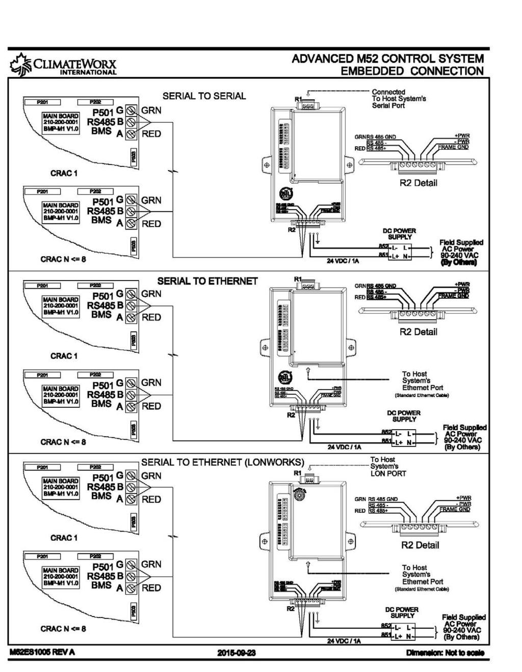
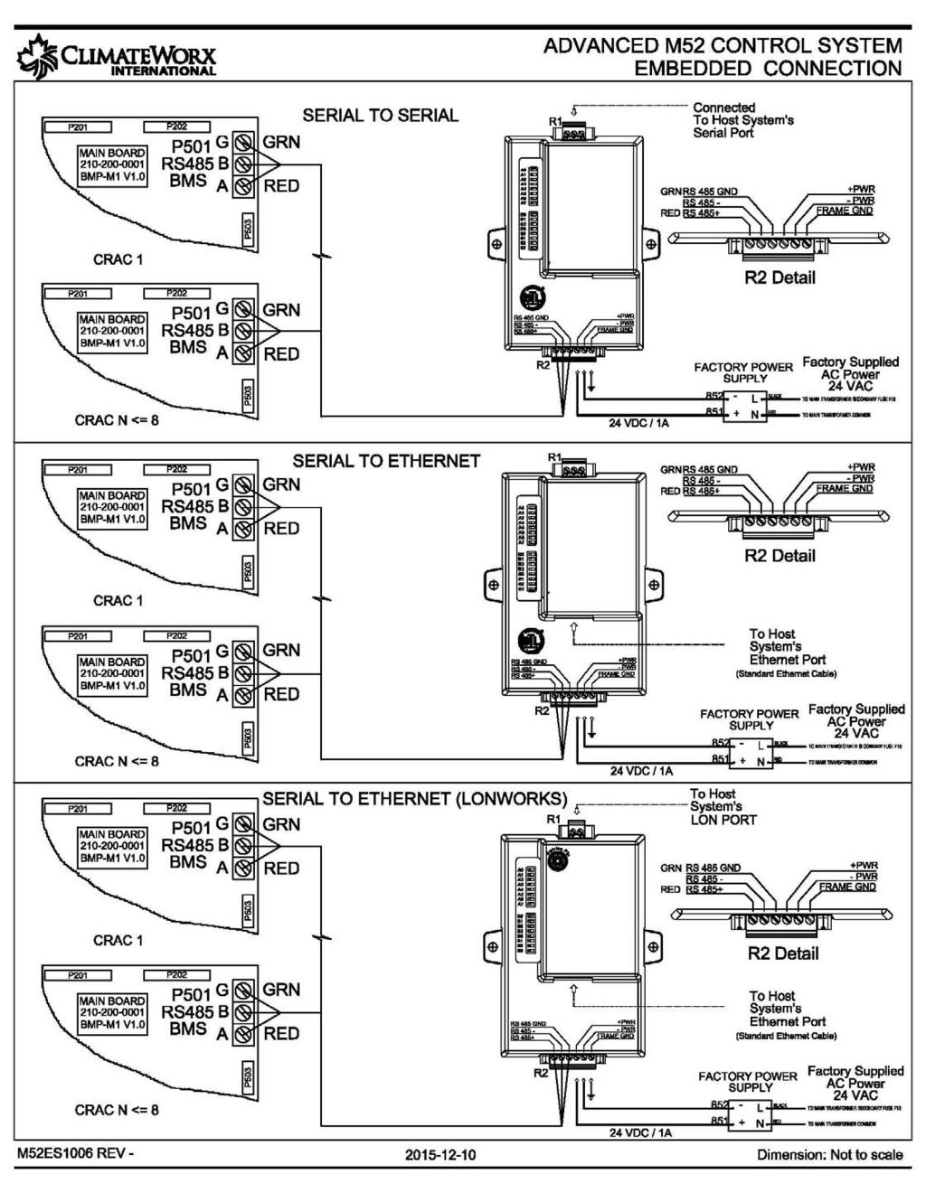
22 Appendix A: Electrical Schematic Diagrams Drawing Title Electric Schematic Air-Cooled General, Electric Schematic Water/ Glycol-Cooled General, Electric Schematic Chilled Water General, Electric Schematic Dual Cooling Air General, Electric Schematic Dual Cooling Water or Glycol General, Electric Schematic Free Cooling General, Electric Schematic Field Wiring Standby Start/ Standby Enable, For automatic change over Electric Schematic Co-Work I2C Interconnection Link Electric Schematic RS485 ModBus RTU Connection, Serial Communication Link Electric Schematic Embedded Connection, Serial to Serial or Ethernet Communication Link remote power Electric Schematic Embedded Connection, Serial to Serial or Ethernet Communication Link factory power Drawing no. ES9030 ES9065 ES9050 ES9030 ES9040 ES9070 M52ES05 M52ES1003 M52ES1004 M52ES1005 M52ES
23 - 23 -
24 - 24 -
25 - 25 -
26 - 26 -
27 - 27 -
28 - 28 -
29 - 29 -
30 - 30 -
31 - 31 -
32 - 32 -
33 - 33 -
34 - 34 -
Series 6, Vertical Floor-Mount Units
 MISSION CRITICAL Air Conditioning Systems Series 6, Vertical Floor-Mount Units Installation Manual ClimateWorx International Inc. 14 Chelsea Lane, Brampton, Ontario, Canada L6T 3Y4 2 Table of Contents
Series 6, Vertical Floor-Mount Units
 MISSION CRITICAL Air Conditioning Systems Series 6, Vertical Floor-Mount Units Installation Manual ClimateWorx International Inc. 14 Chelsea Lane, Brampton, Ontario, Canada L6T 3Y4 2 Table of Contents
12 In Row. Installation Manual. MISSION CRITICAL Air Conditioning Systems. ClimateWorx International Inc.
 MISSION CRITICAL Air Conditioning Systems 12 In Row Installation Manual ClimateWorx International Inc. 14 Chelsea Lane, Brampton, Ontario, Canada L6T 3Y4 2 Table of Contents Table of Contents... 3 Site
Series 11, Ceiling Units
 MISSION CRITICAL Air Conditioning Systems Series 11, Ceiling Units Installation Manual ClimateWorx International Inc. 14 Chelsea Lane, Brampton, Ontario, Canada L6T 3Y4 Table of Contents Table of Contents...
Series 11, Ceiling Units
 MISSION CRITICAL Air Conditioning Systems Series 11, Ceiling Units Installation Manual ClimateWorx International Inc. 14 Chelsea Lane, Brampton, Ontario, Canada L6T 3Y4 Table of Contents Table of Contents...
Series 9. Commissioning Checklist. MISSION CRITICAL Air Conditioning Systems. ClimateWorx International Inc.
 MISSION CRITICAL Air Conditioning Systems Series 9 Commissioning Checklist S9-CL2017.doc ClimateWorx International Inc. 14 Chelsea Lane, Brampton, Ontario, Canada L6T 3Y4 2 S9-CL2017.doc Commissioning
Condensing Unit Installation and Operating Instructions
 Bulletin WCU_O&I 01 June 2003 Condensing Unit Installation and Operating Instructions WCU Air Cooled Condensing Unit Table of Contents Section 1. Section 2. Section 3. Section 4. Section 5. Section 6.
Condensing Unit Installation and Operating Instructions
 Bulletin ACU_O&I 02 August 2016 Condensing Unit Installation and Operating Instructions ACU Air Cooled Condensers Table of Contents Section 1. General Information... 2 Section 2. Refrigeration Piping...
CS/CD/CP AIR COOLED CONDENSING UNITS (P/N E207120C R2)
") CS*/CD*/CP* Series Air Cooled Condensing Units Operating and Installation Manual CS/CD/CP AIR COOLED CONDENSING UNITS (P/N E207120C R2) TABLE OF CONTENTS I. Receipt of Equipment 2 II. Piping...4 III. System
CS*/CD*/CP* Series Air Cooled Condensing Units Operating and Installation Manual CS/CD/CP AIR COOLED CONDENSING UNITS (P/N E207120C R2) TABLE OF CONTENTS I. Receipt of Equipment 2 II. Piping...4 III. System
Air Cooled Condenser Installation and Operating Instructions
 Bulletin CAC_O&I 02 August 2016 Air Cooled Condenser Installation and Operating Instructions CAC Air Cooled Condensers Table of Contents Section 1. General Information... 2 Section 2. Refrigeration Piping...
Service Step by Step Trouble-Shooting Check-List
 WARNING: Only Data Aire trained technician or experience technicians should be working on Data Aire Equipment. Protect yourself at all times and work safe. Date: Dates at the job site: From: to Job#: Serial#:
PARALLEL RACK SYSTEM INSTALLATION & OPERATIONS MANUAL With Master Rack Compressor Sequencer
 PARALLEL RACK SYSTEM INSTALLATION & OPERATIONS MANUAL With Master Rack Compressor Sequencer 5/16 Rev. A 57-02509 2 Contents INTRODUCTION... 4 WARNING LABELS AND SAFETY INSTRUCTIONS... 5 PS SERIES PARALLEL
PDF Created with deskpdf PDF Writer - Trial ::
 Instruction Manual Index Introduction Uncrating and Checking for Damage Locating Your Unit Installation Fill Tank Process Connections Pre Startup Startup Sequence Trouble Shooting Chart Operating Lights
Eclipse Technical Training CME686 CME810 CP686 CP886 CP1086
 Eclipse Technical Training CME686 CME810 CP686 CP886 CP1086 In This Presentation What Eclipse is Components and their functions Installation Operation Maintenance Service Diagnosis The Eclipse System The
DTW Works Master Specification Version 2006 Issued 2006/08/01 Section15621 Packaged Reciprocating Water Chillers Page 1 of 5
 Issued 2006/08/01 Section15621 Packaged Reciprocating Water Chillers Page 1 of 5 PART 1 GENERAL 1.1 RELATED SECTIONS.1 Section 01330 Submittal Procedures..2 Section 01355 Waste Management and Disposal..3
Installation, Operation, and Maintenance Information
 Installation, Operation, and Maintenance Information Air Cooled Condensers 8-2016 Rev 0 Table of Contents General Safety Information 2 Inspection 2 Installation 2 6 Rigging and Assembly 2 Unit Location
TECHNICAL GUIDE DESCRIPTION SPLIT-SYSTEM AIR-COOLED CONDENSING UNITS MODELS: HF-07 FEATURES B-0703
 TECHNICAL GUIDE SPLIT-SYSTEM AIR-COOLED CONDENSING UNITS MODELS: HF-07 DESCRIPTION These Sunline 2000 units are completely assembled, piped and wired at the factory to provide one-piece shipment and rigging.
Contour TM Screw Compressors
 Contour TM Screw Compressors Semi-Hermetic Compact Operating Instruction SCH1 High Temp Compressors Form No. 99-77 1. Introduction This series of semi-hermetic compact screw compressors is designed for
WMHP Series R410a Heat Pump INSTALLATION INSTRUCTIONS
 WMHP Series R410a Heat Pump INSTALLATION INSTRUCTIONS **WARNING TO INSTALLER, SERVICE PERSONNEL AND OWNER** Altering the product or replacing parts with non authorized factory parts voids all warranty
YCIV Hz & Hz
 YCIV 0590-1500 50Hz & 0157-0397 60Hz Start-up Checklist SERVICE POLICY & PROCEDURES Supersedes: Nothing Form 201.23-CL1 (309) Commissioning PREPARATION Commissioning of this unit should only be carried
1025, BOUL. MARCEL-LAURIN INSTRUCTION MANUAL FOR WATER COOLED ENVIROCHILL CHILLER. Prepared par Claude Gadoury, P. Eng MTL TECHNOLOGIES INC.
 WYETH-AYERST CANADA INC. 1025, BOUL. MARCEL-LAURIN S T - L A U R E N T, Q U É B E C INSTRUCTION MANUAL FOR WATER COOLED ENVIROCHILL CHILLER MODEL P448800LT--55WC--22C66S Prepared par Claude Gadoury, P.
Direct Drive Fluid Coolers
 H-IM-68 March 2000 Part No. 25001301 Replaces H-IM-44 Direct Drive Fluid Coolers Installation and Maintenance Data Table of Contents Inspection System Warranty Installation...2 Rigging Instructions...3
Installation Instructions
 24AHA4 Performance Series Air Conditioner with Puron Refrigerant 1-1/2 to 5 Nominal Tons Installation Instructions Fig. 1-24AHA4 A07532 SAFETY CONSIDERATIONS Improper installation, adjustment, alteration,
Series 8. Guide Specification 60 Hz. MISSION CRITICAL Air Conditioning Systems. ClimateWorx International Inc.
 MISSION CRITICAL Air Conditioning Systems Series 8 Guide Specification 60 Hz S8-GS-602017.doc 2014 ClimateWorx International Inc. 14 Chelsea Lane, Brampton, Ontario, Canada L6T 3Y4 Series 8 Guide Specification-60
June 2001 / BULLETIN Way Valves. The right solenoid valve for any job.
 June 01 / BULLETIN - 3-Way Valves The right solenoid valve for any job. Page 2 / Bulletin - Advantages Sporlan 3-Way Valves 3-Way Pilot eliminates costly high- to low-side leaks. "B" reduces total installed
TECHNICAL MANUAL CX(E) SPLIT SYSTEMS. Tel: Fax:
 SPLIT SYSTEMS. Tel: Fax:") TECHNICAL MANUAL CX(E) SPLIT SYSTEMS CONTENTS INDEX PART NUMBERS, OPTIONS, UNIT COMBINATIONS, DIMENSIONS & WEIGHTS 3 PERFORMANCE DATA & AIR FLOW 4 SOUND POWER AND SOUND PRESSURE LEVELS 5 ELECTRICAL DATA
TECHNICAL MANUAL CX(E) SPLIT SYSTEMS CONTENTS INDEX PART NUMBERS, OPTIONS, UNIT COMBINATIONS, DIMENSIONS & WEIGHTS 3 PERFORMANCE DATA & AIR FLOW 4 SOUND POWER AND SOUND PRESSURE LEVELS 5 ELECTRICAL DATA
Table of Contents. Service Procedures. Service Procedures. Measuring Superheat (4) Measuring Subcooling (5) Airflow Calculation (6-8)
 Measuring Subcooling (5) Airflow Calculation (6-8)") Table of Contents Refrigeration Cycle Service Procedures Measuring Superheat (4) Measuring Subcooling (5) Airflow Calculation (6-8) Solving Problems Identifying Low System Charge (9-11) Identifying High
Table of Contents Refrigeration Cycle Service Procedures Measuring Superheat (4) Measuring Subcooling (5) Airflow Calculation (6-8) Solving Problems Identifying Low System Charge (9-11) Identifying High
Installation Instructions
 PREFERREDT SERIES AIR CONDITIONER WITH PURONR REFRIGERANT 1-1/2 TO 5 NOMINAL TONS Installation Instructions Fig. 1 --- 538A NOTE: Read the entire instruction manual before starting the installation. TABLE
APPLICATION DATA SHEET
 APPLICATION DATA SHEET General Piping Recommendations and Refrigerant Line Length for Split-System Air Conditioners and Heat Pumps GENERAL GUIDELINES This Split-System (Air Conditioning Condensing/Heat
EQ Series Portable Chillers
 EQ Series Portable Chillers Installation, Operation and Maintenance Manual Copyright Thermal Care Inc. 2010 Table of Contents Foreword... 1 Installation... 1 Receiving Inspection... 1 Rigging, Handling,
Air-Cooled Condensers
 Air-Cooled Condenser Installation & Operation Bulletin No. H-IM-90 February 2017 Part Number 25007301 Replaces H-IM-90, October 2015 Air-Cooled Condensers Installation and Operation Guide Applicable for
UNDERCOUNTER LABORATORY REFRIGERATORS and FREEZERS Installation, Operation and Maintenance Instructions
 UNDERCOUNTER LABORATORY REFRIGERATORS and FREEZERS Installation, Operation and Maintenance Instructions INSPECTION When the equipment is received, all items should be carefully checked against the bill
Liebert CSU3000 Chiller
 CSI 15620 - Packaged Water Chillers Liebert CSU3000 Chiller Guide Specifications for 7.5-37 Ton CS/CD/CT Models 1.0 GENERAL 1.1 CS/CD MODELS The main-frame coolant supply unit shall be a Liebert Model,
Installation Owner Diagnostics
 Installation Owner Diagnostics Split System Cooling Condensers Model CTA 7 1/2 to 15 Tons Models A and later Design Sequence CTA 090A***A 60 HZ 120A***A 60 HZ 120B***A 60 HZ 180B***A 60 HZ SS-SVN11A-EN
Installation Instructions
 Installation Instructions B-Series VT40, VT60, VT100 Important Safety Notice. This information is intended for use by individuals possessing adequate backgrounds of electrical, refrigeration and mechanical
EQUIPMENT PRE-STARTUP AND STARTUP CHECKLIST TEL NO: ORDER NO: CONTRACT NO:
 Supersedes: (316) Form QTC4-CL2 (617) MODEL QTC4 EQUIPMENT PRE-STARTUP AND STARTUP CHECKLIST CUSTOMER: ADDRESS: PHONE: JOB NAME: LOCATION: CUSTOMER ORDER NO: TEL NO: ORDER NO: CONTRACT NO: CHILLER MODEL
DLCLRA. INSTALLATION INSTRUCTIONS Outdoor Unit Single Zone Ductless System Sizes 36 to 58 TABLE OF CONTENTS
 DLCLRA INSTALLATION INSTRUCTIONS Outdoor Unit Single Zone Ductless System Sizes 36 to 58 Fig. 1 - Size 36 TABLE OF CONTENTS PAGE SAFETY CONSIDERATIONS... 2 PARTS LIST... 3 SYSTEM REQUIREMENTS... 4 WIRING...
EP1 Series Portable Chillers
 USER GUIDE UGH036-0613 www.conairgroup.com EP1 Series Portable Chillers Air-Cooled Models EP1A-01, EP1A-02, EP1A-03 Water-Cooled Models EP1W-02, EP1W-03 Remote Condenser Model EP1R-03 Thank you for purchasing
INSTALLATION AND OPERATING INSTRUCTIONS
 INSTALLATION AND OPERATING INSTRUCTIONS HIGH-EFFICIENCY CONDENSING UNITS RAWD- 6 1 2 & 7 1 2 TON RAWE - 6 1 2 & 7 1 2 TON! RECOGNIZE THIS SYMBOL AS AN INDICATION OF IMPORTANT SAFETY INFORMATION!! WARNING
MODEL YVAA EQUIPMENT PRE-STARTUP AND STARTUP CHECKLIST CUSTOMER: LOCATION: ADDRESS: CUSTOMER ORDER NO: PHONE: JCI CONTRACT NO: JOB NAME:
 Supersedes: 201.28-CL2 (817) Form 201.28-CL2 (1017) MODEL YVAA EQUIPMENT PRE-STARTUP AND STARTUP CHECKLIST CUSTOMER: LOCATION: ADDRESS: PHONE: JOB NAME: CUSTOMER ORDER NO: JCI CONTRACT NO: CHILLER MODEL
WKS 2200 SERIES (USA only) --INSTALLATION INSTRUCTIONS--
 --INSTALLATION INSTRUCTIONS--") 8610 Production Avenue San Diego, California 92121 (858) 566-7465 Fax (858) 566-1943 WWW.BREEZAIRE.COM WKS 2200 SERIES (USA only) --INSTALLATION INSTRUCTIONS-- Thank you for choosing a BREEZAIRE cooling
8610 Production Avenue San Diego, California 92121 (858) 566-7465 Fax (858) 566-1943 WWW.BREEZAIRE.COM WKS 2200 SERIES (USA only) --INSTALLATION INSTRUCTIONS-- Thank you for choosing a BREEZAIRE cooling
INSTALLATION, COMMISSIONING AND OPERATING MANUAL
 INSTALLATION, COMMISSIONING AND OPERATING MANUAL 1 YTBV-D-CE42_0109 CONTENT Available models and capacities Supplier information Warranty Safety Emergency stops/ shutdowns About this manual Models Physical
Series 6. Guide Specification 60 Hz. MISSION CRITICAL Air Conditioning Systems. ClimateWorx International Inc.
 MISSION CRITICAL Air Conditioning Systems Series 6 Guide Specification 60 Hz S6-GS-602017.doc ClimateWorx International Inc. 14 Chelsea Lane, Brampton, Ontario, Canada L6T 3Y4 Series 6 Guide Specification-60
Daikin Direct Expansion (DX) Cooling Coils
 Cooling Coils") Installation and Maintenance Manual IM 902 Daikin Direct Expansion (DX) Cooling Coils Group: Applied Air Part Number: IM 902 Date: February 2008 Types EN, EF, ER, EJ, EK 2008 Daikin Applied Contents Introduction...
Installation and Maintenance Manual IM 902 Daikin Direct Expansion (DX) Cooling Coils Group: Applied Air Part Number: IM 902 Date: February 2008 Types EN, EF, ER, EJ, EK 2008 Daikin Applied Contents Introduction...
TABLE OF CONTENTS. NOTE: Read the entire instruction manual before starting the installation. TROUBLESHOOTING... 13
 R 410A Duct Free Split System Air Conditioner and Heat Pump Product Family: DFS4(A/H) System, DFC4(A/H)3 Outdoor, DFF4(A/H)H Indoor NOTE: Read the entire instruction manual before starting the installation.
Liebert CRV Warranty Inspection Check Sheet
 The following information must be fully completed and forwarded to your local Liebert sales office to establish your equipment warranty. Installer Address Owner Address Owner e-mail address Date of Installation
NOTE: Special care should be given to those areas where these symbols appear.
 CONGRATULATIONS ON THE SELECTION OF A DATA AIRE PRECISION ENVIRONMENTAL CONTROL SYSTEM. PROPER INSTALLATION, OPERATION AND MAINTENANCE OF THIS EQUIPMENT WILL ENSURE YEARS OF OPTIMAL PERFORMANCE. There
Installation, Operation and Maintenance Manual. LQ Series. Portable Chillers 7 to 40 Tons
 Installation, Operation and Maintenance Manual LQ Series Portable Chillers 7 to 40 Tons Copyright Thermal Care Inc. 2011 Page intentionally blank Table of Contents Foreword... 1 Installation... 1 Receiving
WKS 4000 SERIES (USA only) --INSTALLATION INSTRUCTIONS--
 --INSTALLATION INSTRUCTIONS--") 8610 Production Avenue San Diego, California 92121 (858) 566-7465 Fax (858) 566-1943 WKS 4000 SERIES (USA only) --INSTALLATION INSTRUCTIONS-- Thank you for choosing a BREEZAIRE cooling unit. We believe
8610 Production Avenue San Diego, California 92121 (858) 566-7465 Fax (858) 566-1943 WKS 4000 SERIES (USA only) --INSTALLATION INSTRUCTIONS-- Thank you for choosing a BREEZAIRE cooling unit. We believe
WineZone Ceiling Mount Ductless Split 15
 WineZone Ceiling Mount Ductless Split 15 Requires an HVAC technician to install and charge with R-22 refrigerant. Easy to install. Unit plugs into wall outlet. Industrial grade unit for longer life. Indoor
INSTALLATION MANUAL SPLIT-SYSTEM CONDENSING UNITS (AIR COOLED) HB Ton HB Ton HB Ton NOTES, CAUTIONS AND WARNINGS
 HB Ton HB Ton HB Ton NOTES, CAUTIONS AND WARNINGS") INSTALLATION MANUAL SPLIT-SYSTEM CONDENSING UNITS (AIR COOLED) CONTENTS GENERAL................................... 5 SAFETY CONSIDERATIONS.................... 5 AGENCY APPROVALS.........................
INSTALLATION MANUAL SPLIT-SYSTEM CONDENSING UNITS (AIR COOLED) CONTENTS GENERAL................................... 5 SAFETY CONSIDERATIONS.................... 5 AGENCY APPROVALS.........................
TRI-PLATE B INSTALLATION, OPERATION, AND MAINTENANCE INSTRUCTIONS PART NO EFFECTIVE MARCH 1, 1983 REPRINT APRIL 16, 1999
 TRI-PLATE B INSTALLATION, OPERATION, AND MAINTENANCE INSTRUCTIONS PART NO. 8801469 EFFECTIVE MARCH 1, 1983 REPRINT APRIL 16, 1999 THE MILK COOLING SYSTEMS SPECIALISTS TM FRE-HEATER Part No. 8801469 Table
AMERICAN EQUIPMENT SYSTEMS A Division Of Trevor-Martin Corporation th Terrace North Clearwater, Florida 33762
 AMERICAN EQUIPMENT SYSTEMS A Division Of Trevor-Martin Corporation 4151 112 th Terrace North Clearwater, Florida 33762 COMMERCIAL REFRIGERANT DESUPERHEATER WASTE HEAT RECOVERY INSTALLATION/OPERATION/MAINTENANCE
Table of Contents. Page 2 of 28
 Rev. 1.1 Table of Contents Page Introduction 3 System Description 4 Electrical & Physical Data 5-6 Description of Electrical Controls 7-8 Chiller Controls Sequence of Operation 9 System Faults 10 Refrigeration
Installation Manual BCS2000/3000
 Installation Manual BCS2000/3000 Supplies Needed for Installation 1. 3/8 and 5/8 copper tubing. 2. 1/4 copper water supply 3. 1/4 condensate vinyl drain tube/tube clamps 4. Provide 120v 15A circuit for
Installation Instructions
 8GXM / 0GXM Multi---Split High---Wall Duct Free Split System 8GXM --- Size 18k, k, and 0k 0GXM --- Size 9k, 1k, and 18k Installation Instructions NOTE: Read the entire instruction manual before starting
AIR CONDITIONING. Carrier Corporation 2002 Cat. No
 AIR CONDITIONING Carrier Corporation 2002 Cat. No. 020-016 1. This refresher course covers topics contained in the AIR CONDITIONING specialty section of the North American Technician Excellence (NATE)
CROWN. Boiler Co. Santa-Fe Series. Hydronic Air Handlers INSTALLATION, OPERATION & MAINTENANCE INSTRUCTIONS
 CROWN Boiler Co Santa-Fe Series Hydronic Air Handlers INSTALLATION, OPERATION & MAINTENANCE INSTRUCTIONS These instructions must be affixed on or adjacent to the air handler Models: SAC049A20 SAC059A25
Series PS6, Vertical Floor-Mount Units
 Series PS6, Vertical Floor-Mount Units Technical Data 60 Hz sps6em6ea.doc Dec-12 ClimateWorx International Inc. 14 Chelsea Lane, Brampton, Ontario, Canada L6T 3Y4 Table of Contents Table of Contents...
Installation 50% Service 20% Components 20% Applied Knowledge 10%
 LIGHT COMMERCIAL REFRIGERATION INSTALLATION CERTIFICATION Certification Information Scope - Tests a candidate's knowledge of the installation, service, maintenance, and repair of Light Commercial Refrigeration
38GHP AIR-COOLED MULTI SPLIT CONDENSING UNITS
 Concepcion Carrier Air conditioning Company Philippines INSTALLATION MANUAL, START-UP & SERVICE INSTRUCTIONS 38GHP AIR-COOLED MULTI SPLIT CONDENSING UNITS CONTENTS: Physical Data and Dimensions........
College of Technological Studies Department of Power & Refrigeration Technology. Course Contents
 College of Technological Studies Department of Power & Refrigeration Technology Course Contents Course Designation: Air Conditioning Control systems Course No. : 272 0463 Credit Hrs.: 3 Lecture Hrs.: 2
.2 Section Waste Management and Disposal.
 Issued 2005/06/01 Section 15624 Packaged Rotary Screw Water Chillers Page 1 of 5 PART 1 General 1.1 RELATED SECTIONS.1 Section 01330 Submittal Procedures..2 Section 01355 Waste Management and Disposal..3
BASIC HEAT PUMP THEORY By: Lloyd A. Mullen By: Lloyd G. Williams Service Department, York Division, Borg-Warner Corporation
 INTRODUCTION In recent years air conditioning industry technology has advanced rapidly. An important byproduct of this growth has been development of the heat pump. Altogether too much mystery has surrounded
SERVICING PROCEDURE R-410A LEAK TEST EVACUATION CHARGING. Bard Manufacturing Company, Inc. Bryan, Ohio Manual Page 1 of 11
 SERVICING PROCEDURE R-410A LEAK TEST EVACUATION CHARGING Bard Manufacturing Company, Inc. Bryan, Ohio 43506 Since 1914...Moving ahead, just as planned. Manual No.: 2100-479 Supersedes: NEW File: Volume
Installation, Start-Up and Service Instructions
 38AH044-134 Air-Cooled Condensing Units 50/60 Hz Installation, Start-Up and Service Instructions CONTENTS Page SAFETY CONSIDERATIONS...................... 1 INSTALLATION................................
Installation Instructions
 Performance Series Heat Pumps with PURONr Refrigerant 1 --- 1/2 to 5 Nominal Tons Installation Instructions Fig. 1 --- A07532 NOTE: Read the entire instruction manual before starting the installation.
B. Unit construction shall comply with ASHRAE 15 Safety Code, NEC, and ASME applicable codes (U.S.A. codes).
.") Guide Specifications PART 1 GENERAL 1.01 SYSTEM DESCRIPTION Microprocessor controlled, air-cooled liquid chiller utilizing scroll compressors, low sound fans, hydronic pump system and optional fluid storage
Guide Specifications PART 1 GENERAL 1.01 SYSTEM DESCRIPTION Microprocessor controlled, air-cooled liquid chiller utilizing scroll compressors, low sound fans, hydronic pump system and optional fluid storage
User s Information and Installation Instructions
 Outdoor Air Conditioner User s Information and Installation Instructions 13 SEER R-410A High Efficiency Split System These units have been designed and tested for capacity & efficiency in accordance with
Installation Instructions
 38MHR Outdoor Unit Single Zone Ductless System Sizes 09 to 24 Installation Instructions NOTE: Read the entire instruction manual before starting the installation. NOTE: Images are for illustration purposes
Rev B, 9/2/2009. Kodiak Chiller Overview
 930-0001 Rev B, 9/2/2009 Kodiak Chiller Overview Presentation Outline Phone: 781-933-7300 Lytron Technical Support Contact Information 3 Introduction 4 Part I: Unpacking 5 Part II: Installation 7 Part
User s Information and Installation Instructions
 Outdoor Air Conditioner User s Information and Installation Instructions 2-Stage R-410A Split System These units have been designed and tested for capacity & efficiency in accordance with A.H.R.I. Standards.
TECHNICAL GUIDE. Description SPLIT-SYSTEM AIR-COOLED CONDENSING UNITS YD360, 480 & THRU 50 NOMINAL TONS YTG-B-0811
 Description These units are completely assembled, piped and wired at the factory to provide one-piece shipment and rigging. Each unit is pressurized with a holding charge of Refrigerant R-410A for storage
30GH Air-Cooled Liquid Chillers 30GH Nominal cooling capacity kw
 Air-Cooled Liquid Chillers Nominal cooling capacity 21-94 kw Carrier is participating in the Eurovent Certification Programme. Products are as listed in the Eurovent Directory of Certified Products. The
Owners Manual Refrigerated Air Dryer MHT SERIES
 Owners Manual Refrigerated Air Dryer MHT SERIES IMPORTANT: READ THIS MANUAL CAREFULLY. IT CONTAINS IN- FORMATION ABOUT SAFETY AND THE SAFETY OF OTHERS. ALSO BECOME FAMILAR WITH THE PROPER INSTALLATION
MAC-120HE-03 Air-Cooled Chiller
 MAC-120HE-03 Air-Cooled Chiller 10 Ton / 120,000 BTUH Air-Cooled Chiller 380/415/460-3-50/60 1 HVAC Guide Specifications Air-Cooled Liquid Chiller Nominal Size: 10 Tons Multiaqua Model Number: MAC-120HE-03
NetworkAIR FM Precision Air Conditioner. Installation
 NetworkAIR FM Precision Air Conditioner Installation Contents General Information...1 Receiving the Equipment.............................. 1 Receive and inspect the Module...................... 1 Storing
Multiaqua Chiller Manual
 Rev. 1.1 Multiaqua Chiller Manual The Multiaqua Chiller System is the only air conditioning/refrigeration system of its kind in the world today offering the degree of application flexibility described
LABORATORY AIR COMPRESSORS AND VACUUM PUMPING SYSTEMS
 SECTION 22 20 00 LABORATORY AIR COMPRESSORS AND VACUUM PUMPING SYSTEMS PART 1 - GENERAL 1.1 RELATED DOCUMENTS: A. The Conditions of the Contract and applicable requirements of Division 1, "General Requirements",
Surna 25-Ton Chiller Operating & Maintenance Manual
 www.surna.com 303.993.5271 Surna 25-Ton Chiller Operating & Maintenance Manual Models: 300F3-3. 300F4-3, 300FW-3 Revised: July 2015 Table of Contents Warranty Information 4 Limited Warranty 4 Limitation
NON-CYCLING REFRIGERATED AIR DRYERS. RNC Series
 NON-CYCLING REFRIGERATED AIR DRYERS RNC Series Durability Delivered Gardner Denver RNC Series refrigerated air dryers are engineered to benefit you today and tomorrow. Quality components and engineering
NON-CYCLING REFRIGERATED AIR/GAS DRYERS QPNC 75 to QPNC 250 OPERATOR S MANUAL
 NON-CYCLING REFRIGERATED AIR/GAS DRYERS QPNC 75 to QPNC 250 OPERATOR S MANUAL DATE OF PURCHASE: MODEL: SERIAL NO.: Record above information from nameplate. Retain this information for future reference.
Single Package Vertical Unit (SPVU) Installation, Operation and Maintenance Manual Effective August 2018
 Installation, Operation and Maintenance Manual Effective August 2018") VertiCool CLASSIC Single Package Vertical Unit (SPVU) Installation, Operation and Maintenance Manual Effective August 2018 Air-Cooled, Water-Cooled, Chilled Water and Water Source Heat Pump Contents Installation,
VertiCool CLASSIC Single Package Vertical Unit (SPVU) Installation, Operation and Maintenance Manual Effective August 2018 Air-Cooled, Water-Cooled, Chilled Water and Water Source Heat Pump Contents Installation,
INSTALLATION MANUAL. Split-type Air Conditioner (Cooling and Heating) Outdoor Unit UQB09JJWC UQB12JJWC. Indoor Unit AQB09JJWC AQB12JJWC
 Outdoor Unit UQB09JJWC UQB12JJWC. Indoor Unit AQB09JJWC AQB12JJWC") AQB09JJ6WC_IM_E_2585 2006.4.17 4:26 PM Page 17 INSTALLATION MANUAL Indoor Unit AQB09JJWC AQB12JJWC Outdoor Unit UQB09JJWC UQB12JJWC ENGLISH FRANÇAIS ESPAÑOL Split-type Air Conditioner (Cooling and Heating)
AQB09JJ6WC_IM_E_2585 2006.4.17 4:26 PM Page 17 INSTALLATION MANUAL Indoor Unit AQB09JJWC AQB12JJWC Outdoor Unit UQB09JJWC UQB12JJWC ENGLISH FRANÇAIS ESPAÑOL Split-type Air Conditioner (Cooling and Heating)
WILKERSON MODELS DE3, DE4 AND DE5 COMPACT HEATLESS AIR DRYERS
 INSTRUCTION MANUAL FOR WILKERSON MODELS DE3, DE4 AND DE5 COMPACT HEATLESS AIR DRYERS DE3 - DE5 OPERATIONS GENERAL This instruction manual covers the installation, operation, maintenance and troubleshooting
Mission Critical. Series 6, 8 & 9. vertical floor mount Ton Units. Air Conditioning Systems
 Mission Critical Air Conditioning Systems vertical floor mount Series 6, 8 & 9 2-30 Ton Units Single Circuit for Superior Economy and Dual Circuit for Ultimate Protection Series 6 2-5 tons Compact Footprint
VS SERIES NH3 STEAM VAPORIZERS OPERATION MANUAL
 VS SERIES NH3 STEAM VAPORIZERS Revised March 1997 OPERATION MANUAL CONTENTS PAGE 1. GENERAL................................... 1 Figure 1-1 - VS Series Vaporizer......................... B How to Select
EBAC MODEL K100 DEHUMIDIFIER OWNER S MANUAL
 EBAC MODEL K100 DEHUMIDIFIER OWNER S MANUAL Ebac Industrial Products 700 Thimble Shoals Boulevard Newport News VA 23606-2575 Telephone (757) 873-6800 Fax (757) 873-3632 Website: www.ebacusa.com INTRODUCTION
PACKAGED AIR COOLED Product Data Catalog
 PACKAGED AIR COOLED Product Data Catalog MODELS ASP-10A ASP-15A ASP-20A ASP-00P ASP-00F ASP-00G A MEMBER OF MARDUK HOLDING COMPANY, LLC The Leader in Modular Chillers ETL and CSA Approved CHILLER MODULES
Method to test HVAC equipment at part load conditions
 IPLV Method to test HVAC equipment at part load conditions For water cooled chillers: 100% load ( % hrs) + 75% ( Hrs ) + 50% ( Hrs ) + 25% ( Hrs ) = IPLV value Manufacturer can favor this number by tweaking
Installation, Operation and Maintenance Manual. LQ Series Portable Chillers
 Installation, Operation and Maintenance Manual LQ Series Portable Chillers Table of Contents Foreword... 1 Installation... 1 Receiving Inspection... 1 Rigging, Handling, and Locating Equipment... 1 Electrical
NO. F ISSUED: JUN. 15, 2009 REVISED: HOSHIZAKI MODULAR CRESCENT CUBER KMD-201AA KMD-201AWA MODEL SERVICE MANUAL
 NO. F037-775 ISSUED: JUN. 15, 2009 REVISED: HOSHIZAKI MODULAR CRESCENT CUBER MODEL KMD-201AA KMD-201AWA SERVICE MANUAL CONTENTS PAGE I. SPECIFICATIONS ---------------------------------------------------------------------------------------
INSTALLATION MANUAL COMMERCIAL SPLIT SYSTEM COOLING UNITS 4 PIPE SYSTEMS 15 THROUGH 20 NOMINAL TON HB B-0804
 INSTALLATION MANUAL COMMERCIAL SPLIT SYSTEM COOLING UNITS 4 PIPE SYSTEMS 15 THROUGH 20 NOMINAL TON CONTENTS GENERAL................................. 3 REFERENCE............................... 3 INSPECTION...............................
CONDENSING UNITS SPLIT-SYSTEM COOLING 6-1/3 TONS INSTALLATION INSTRUCTION MODELS H*DB076 NOMENCLATURE GENERAL LIMITATIONS INSPECTION REFERENCE
 INSTALLATION INSTRUCTION CONDENSING UNITS SPLIT-SYSTEM COOLING 6-1/3 TONS Supersedes: Nothing 550.38-N6Y (1095) MODELS H*DB076 035-13578 WARNINGS are given to alert the installer that severe personal injury,
User s Information/Installation Instructions
 Outdoor Heat Pump User s Information/Installation Instructions 12 SEER High Efficiency Split System These units have been designed and tested for capacity and efficiency in accordance with A.R.I. Standards.
SECTION REFRIGERATION EQUIPMENT. A. Section Includes: Refrigeration equipment for insulated cold storage rooms including necessary accessories.
 SECTION 15650 REFRIGERATION EQUIPMENT PART 1 GENERAL 1.01 SUMMARY A. Section Includes: Refrigeration equipment for insulated cold storage rooms including necessary accessories. B. Related Section: 1. 11400
Installation, Operation, and Maintenance Information
 Installation, Operation, and Maintenance Information Low Velocity Unit Coolers Bulletin No. IOM 110.3 Table of Contents Inspection... 2 Installation... 2 4 General... 2 Location... 2 Drain Line... 3 Refrigerant
DESIGN STANDARDS SECTION 15600
 PART 1 - GENERAL 1.1 Work included: A. Piping, tubing and fittings. B. Piping specialties. C. Special duty valves. D. Refrigerants. E. Chillers. F. Refrigerant monitors. 1.2 General requirements: A. Reciprocating
TECHNICAL GUIDE DESCRIPTION SPLIT-SYSTEM AIR-COOLED CONDENSING UNITS. HA300, HB360, HB480 & HB thru 50 NOMINAL TONS (50 Hz)
") DESCRIPTION These units are completely assembled, piped and wired at the factory to provide one-piece shipment and rigging. Each unit is pressurized with a holding charge of refrigerant-22 for storage
DESCRIPTION These units are completely assembled, piped and wired at the factory to provide one-piece shipment and rigging. Each unit is pressurized with a holding charge of refrigerant-22 for storage
DUNHAM-BUSH. Request for start-up and commissioning of Dunham-Bush chillers (Water Cooled or Air Cooled) and Condensing Units.
 and Condensing Units.") DUNHAM-BUSH Request for start-up and commissioning of Dunham-Bush chillers (Water Cooled or Air Cooled) and Condensing Units. Job Name Unit Model Address & Location Unit Serial Number of Units Kindly complete,
DUNHAM-BUSH Request for start-up and commissioning of Dunham-Bush chillers (Water Cooled or Air Cooled) and Condensing Units. Job Name Unit Model Address & Location Unit Serial Number of Units Kindly complete,