CS-XE9EKE CU-XE9EKE CS-XE12EKE CU-XE12EKE
|
|
|
- Clarence Harrell
- 5 years ago
- Views:
Transcription

1 Order No. MAC C8 Air Conditioner CS-XE9EKE CU-XE9EKE CS-XE12EKE CU-XE12EKE TABLE OF CONTENTS PAGE 1 Safety Precautions Specifications CS-XE9EKE CU-XE9EKE CS-XE12EKE CU-XE12EKE Features Location of Controls and Components Indoor Unit Outdoor Unit Remote Control Dimensions Indoor Unit & Remote Control Outdoor Unit Refrigeration Cycle Diagram Block Diagram Wiring Connection Diagram Indoor Unit Outdoor Unit Printed Circuit Board Indoor Unit PAGE 9.2. Indicator Diagnosis Outdoor Unit Installation Instruction Select The Best Location Indoor Unit Outdoor Unit Operation and Function Basic Function Airflow Direction Quiet operation (Cooling Mode/Cooling area of Dry Mode) Powerful Mode Operation ON Timer Control OFF Timer Control Auto Restart Control Remote Control Signal Receiving Sound Filter Cleaning Control Ventilation Control
2 12 Protection Control Time Delay Safety Control Seconds Forced Operation Total Running Current Control IPM (Power transistor) Protection Control (DC Peak detection Compressor Overheating Prevention Control Outdoor High Pressure Prevention Control (Cooling and Dry operations) Compressor Protection Control (Refrigeration Cycle Abnormality) Four-way Valve Operation Detection Control (Switching Abnormality between Cooling and Heating) Anti-Freezing Control (Cooling and Dry operations) Outdoor Air Temperature Control Indoor Intake Air Temperature Control (Heating operation) Servicing Mode Auto OFF/ON Button Various Setting Mode Individual Correspondence Mode Select Remote Control Transmission Code Demo Mode Troubleshooting Guide Refrigeration Cycle System Relationship Between The Condition of The Air Conditioner and Pressure and Electric Current Breakdown Self Diagnosis Function Error Codes Table Movable Front Panel Malfunction Initial Operation After Installation Error During Filter Cleaning Operation Error During Ventilation Operation Disassembly and Assembly Instructions Indoor Electronic Controller, Auto Cleaning, Cross Flow Fan and Fan Motor Removal Procedures Filter Cleaning Device Complete Removal Instructions Ventilation Device Removal Instructions Gear Removal Instructions Outdoor Propeller Fan and Fan Motor Technical Data CS-XE9EKE CU-XE9EKE CS-XE12EKE CU-XE12EKE Sensible Capacity Chart Exploded View and Replacement Parts List Indoor Unit Outdoor Unit
3 1 Safety Precautions Read the following SAFETY PRECAUTIONS carefully before perform any servicing. Electrical work must be installed or serviced by a licensed electrician. Be sure to use the correct rating of the power plug and main circuit for the model installed. The caution items stated here must be followed because these important contents are related to safety. The meaning of each indication used is as below. Incorrect installation or servicing due to ignoring of the instruction will cause harm or damage, and the seriousness is classified by the following indications. This indication shows the possibility of causing death or serious injury. This indication shows the possibility of causing injury or damage to properties. The items to be followed are classified by the symbols: This symbol denotes item that is PROHIBITED from doing. Carry out test running to confirm that no abnormality occurs after the servicing. Then, explain to user the operation, care and maintenance as stated in instructions. Please remind the customer to keep the operating instructions for future reference. 1. Engage dealer or specialist for installation and servicing. If installation or servicing done by the user is defective, it will cause water leakage, electrical shock or fire. 2. Install according to this installation instruction strictly. If installation is defective, it will cause water leakage, electrical shock or fire. 3. Use the attached accessories parts and specified parts for installation and servicing. Otherwise, it will cause the set to fall, water leakage, fire or electrical shock. 4. Install at a strong and firm location which is able to withstand the set s weight. If the strength is not enough or installation is not properly done, the set will drop and cause injury. 5. For electrical work, follow the local national wiring standard, regulation and the installation instruction. An independent circuit and single outlet must be used. If electrical circuit capacity is not enough or defect found in electrical work, it will cause electrical shock or fire. 6. Use the specified cable and connect tightly for indoor/outdoor connection. Connect tightly and clamp the cable so that no external force will be acted on the terminal. If connection or fixing is not perfect, it will cause heat-up or fire at the connection. 7. Wire routing must be properly arranged so that control board cover is fixed properly. If control board cover is not fixed perfectly, it will cause heat-up or fire at the connection point of terminal, fire or electrical shock. 8. When connecting the piping, do not allow air or any substances other than the specified refrigerant to enter the refrigeration cycle. Otherwise, this may lower the capacity, cause abnormally high pressure in the refrigeration cycle, and possibly result in explosion and injury. 9. Thickness of copper pipes used must be more than 0.8 mm. Never use copper pipes thinner than 0.8 mm. 10. It is desirable that the amount of residual oil is less than 40 mg/10m. 11. Do not modify the length of the power supply cord or use of the extension cord, and do not share the single outlet with other electrical appliances. Otherwise, it will cause fire or electrical shock. 1. The equipment must be earthed. It may cause electrical shock if grounding is not perfect. 2. Do not install the unit at place where leakage of flammable gas may occur. In case gas leaks and accumulates at surrounding of the unit, it may cause fire. 3. Carry out drainage piping as mentioned in installation instructions. If drainage is not perfect, water may enter the room and damage the furniture. 4. Pb free solder has a higher melting point than standard solder; typically the melting point is F (30-40 C) higher. Please use a high temperature solder iron. In case of the soldering iron with temperature control, please set it to 700 ± 20 F (370 ± 10 C). Pb free solder will tend to splash when heated too high (about 1100 F / 600 C). 3
4 ATTENTION 1. Selection of the installation location. Select an installation location which is rigid and strong enough to support or hold the unit, and select a location for easy maintenance. 2. Power supply connection to the conditioner. Connect the power supply cord of the air conditioner to the mains using one of the following methods. Power supply point shall be the place where there is ease for ease for access for the power disconnection in case of emergency. In some countries, permanent connection of this room air conditioner to the power supply is prohibited. 1. Power supply connection to the receptacle using a power plug. Use an approved power plug with earth pin for the connection to the socket. 2. Power supply connection to a circuit breaker for the permanent connection. Use an approved circuit breaker for the permanent connection. It must be a double pole switch with a minimum 3.5 mm contact gap. 3. Do not release refrigerant during piping work for installation, servicing, reinstallation and during repairing a refrigeration parts. Take care of the liquid refrigerant, it may cause frostbite. 4. Installation work. It may need two people to carry out the installation work. 5. Do not install this appliance in a laundry room or other location where water may drip from the ceiling, etc. 4
5 2 Specifications 2.1. CS-XE9EKE CU-XE9EKE Unit CS-XE9EKE CU-XE9EKE Performance Test Condition EUROVENT/AS Power Source (Phase, Voltage, Cycle) ø, V, Hz Single, , 50 Cooling Capacity kw 2.60 ( ) kcal/h 2,240 (520-2,580) Heating Capacity kw 3.60 ( ) kcal/h 3,100 (520-5,250) Moisture Removal l/h (Pint/h) 1.6 (3.4) Airflow Method OUTLET SIDE VIEW TOP VIEW INTAKE Air Volume Lo m 3 /min (cfm) Cooling; 7.3 (260) Heating; 7.7 (270) Me m 3 /min (cfm) Cooling; 8.9 (310) Heating; 9.5 (340) Hi m 3 /min (cfm) Cooling; 10.6 (370) Cooling; 29.8 (1,050) Heating; 11.7 (410) SHi m 3 /min (cfm) Cooling; 11.3 (400) Heating; 12.1 (430) Noise Level db (A) Cooling; High 39-39, Low Cooling; High Heating; High 40-40, Low Heating; High Power level db Cooling; High Cooling; High Heating; High Heating; High Electrical Data Input Power W Cooling; 570 ( ) Heating; 810 (115-1,640) Running Current A Cooling; Heating; EER W/W (kcal/hw) Cooling; 4.56 (3.93) COP W/W (kcal/hw) Heating; 4.44 (3.83) Starting Current A 3.8 Piping Connection Port inch G ; Half Union 3/8 G ; 3-way valve 3/8 (Flare piping) inch L ; Half Union 1/4 L ; 2-way valve 1/4 Pipe Size inch G ; (Gas side) 3/8 G ; (Gas side) 3/8 (Flare piping) inch L ; (Liquid side) 1/4 L ; (Liquid side) 1/4 Drain Hose Inner diameter mm 16 Length m 0.65 Power Cord Length m 1.8 Number of core-wire 3 (1.5 mm 2 ) Dimensions Height inch (mm) 12 (305) 21-1/4 (540) Width inch (mm) 34-1/4 (870) 30-23/32 (780) Depth inch (mm) 9-1/32 (229) 11-3/8 (289) Net Weight lb (kg) 29 (13.0) 82 (37) Compressor Description Hermetic Scroll Motor Type Brushless (4-poles) Rated Output W 750 5
6 Unit CS-XE9EKE CU-XE9EKE Air Circulation Description Cross-flow Fan Propeller Fan Material ASG20K1 P.P Motor Type Transistor (8-poles) Induction (8-poles) Input W Rated Output W Fan Speed Low (Cool/Heat) rpm 800 / 850 Medium (Cool/Heat) rpm 980 / 1,050 High (Cool/Heat) rpm 1,170 / 1, /800 SuperHigh (Cool/Heat) rpm 1,250 / 1,340 Heat Exchanger Description Evaporator Condenser Tube material Copper Copper Fin material Aluminium (Pre Coat) Aluminium Fin Type Slit Fin Corrugated Fin Row / Stage (Plate fin configuration, forced draft) 2 / 15 2 / 24 FPI Size (W H L) mm Refrigerant Control Device Exp. Valve Refrigerations Oil (cm 3 ) RB68A (400) Refrigerant (R410A) g (oz) 930 (32.8) Thermostat Electronic Control Protection Device Electronic Control Capillary Tube Length mm Flow Rate I/min Inner Diameter mm Air Filter Material PET Style Compressor Capacitor F, VAC Fan Motor Capacitor F, VAC Note: Specifications are subject to change without notice for further improvement. 6
7 2.2. CS-XE12EKE CU-XE12EKE Unit CS-XE12EKE CU-XE12EKE Performance Test Condition EUROVENT/AS Power Source (Phase, Voltage, Cycle) ø, V, Hz Single, , 50 Cooling Capacity kw 3.50 ( ) kcal/h 3,010 (520-3,440) Heating Capacity kw 4.80 ( ) kcal/h 4,130 (520-5,760) Moisture Removal l/h (Pint/h) 2.0 (4.2) Airflow Method OUTLET SIDE VIEW TOP VIEW INTAKE Air Volume Lo m 3 /min (cfm) Cooling; 8.2 (290) Heating; 9.2 (320) Me m 3 /min (cfm) Cooling; 10.1 (360) Heating; 10.8 (380) Hi m 3 /min (cfm) Cooling; 11.9 (420) Cooling; 31.0 (1,090) Heating; 12.7 (450) SHi m 3 /min (cfm) Cooling; 12.6 (450) Heating; 13.2 (470) Noise Level db (A) Cooling; High 42-42, Low Cooling; High Heating; High 42-42, Low Heating; High Power level db Cooling; High Cooling; High Heating; High Heating; High Electrical Data Input Power W Cooling; 880 (120-1,100) Heating; 1,220 (115-1,840) Running Current A Cooling; Heating; EER W/W (kcal/hw) Cooling; 3.98 (3.42) COP W/W (kcal/hw) Heating; 3.93 (3.39) Starting Current A 5.6 Piping Connection Port inch G ; Half Union 1/2 G ; 3-way valve 1/2 (Flare piping) inch L ; Half Union 1/4 L ; 2-way valve 1/4 Pipe Size inch G ; (Gas side) 1/2 G ; (Gas side) 1/2 (Flare piping) inch L ; (Liquid side) 1/4 L ; (Liquid side) 1/4 Drain Hose Inner diameter mm 16 Length m 0.65 Power Cord Length m 1.8 Number of core-wire 3 (1.5 mm 2 ) Dimensions Height inch (mm) 12 (305) 21-1/4 (540) Width inch (mm) 34-1/4 (870) 30-23/32 (780) Depth inch (mm) 9-1/32 (229) 11-3/8 (289) Net Weight lb (kg) 29 (13.0) 82 (37) Compressor Description Hermetic Scroll Motor Type Brushless (4-poles) Rated Output W 750 Air Circulation Description Cross-flow Fan Propeller Fan Material ASG20K1 P.P Motor Type Transistor (8-poles) Induction (8-poles) Input W Rated Output W Fan Speed Low (Cool/Heat) rpm 900 / 1,000 Medium (Cool/Heat) rpm 1,100 / 1,180 High (Cool/Heat) rpm 1,300 / 1, /820 SuperHigh (Cool/Heat) rpm 1,380 / 1,440 7
8 Unit CS-XE12EKE CU-XE12EKE Heat Exchanger Description Evaporator Condenser Tube material Copper Copper Fin material Aluminium (Pre Coat) Aluminium Fin Type Slit Fin Corrugated Fin Row / Stage (Plate fin configuration, forced draft) 2 / 15 2 / 24 FPI Size (W H L) mm Refrigerant Control Device Exp. Valve Refrigerations Oil (cm 3 ) RB68A (400) Refrigerant (R410A) g (oz) 970 (34.2) Thermostat Electronic Control Protection Device Electronic Control Capillary Tube Length mm Flow Rate I/min Inner Diameter mm Air Filter Material PET Style Compressor Capacitor F, VAC Fan Motor Capacitor F, VAC Note: Specifications are subject to change without notice for further improvement. 8
9 3 Features High Efficiency Compact Design Wider range of horizontal discharge air Long Installation Piping - up to 15 meter for XE9EK & XE12EK SUPER alleru buster - Inactivate various harmful airborne elements including allergens, viruses and bacteria Operation Improvement - Quiet mode to provide quiet operation - Powerful mode to reach the desired room temperature quickly - 24-hour timer setting - Ventilation mode is to ventilate the dirty air of the room to outdoor, to keep the room fresh and clean - Random Auto Restart after power failure for safety restart operation Serviceability Improvement - Removable and washable front panel - Breakdown Self Diagnosis function Filter Cleaning Control - Cleans the filter automatically, to keep optimum performance under clean and comfortable environment. - This built-in cleaning mechanism cleans the filter automatically and minimizes filter clogging - It maintains the original performance of the air conditioner, while eliminates the unpleasant job of manual filter cleaning Environmental Protection - Non-ozone depletion substances refrigerant (R410A). 9


10 4 Location of Controls and Components Note: * Movable front panel will open slightly for air intake purposes once the air conditioner operation starts. Movable front panel will remain open during air conditioner operation. It will close automatically once the air conditioner operation stops. In such a condition, do not interrupt the movable front panel movement as this may cause malfunction or unit breakdown. The above condition does not apply for filter cleaning Indoor Unit 4.3. Remote Control 4.2. Outdoor Unit 10
11 5 Dimensions 5.1. Indoor Unit & Remote Control 11
12 5.2. Outdoor Unit 12
13 6 Refrigeration Cycle Diagram 13
14 7 Block Diagram 14
15 8 Wiring Connection Diagram 8.1. Indoor Unit 15
16 8.2. Outdoor Unit 16

17 9 Printed Circuit Board 9.1. Indoor Unit TOP VIEW 17

18 BOTTOM VIEW 18


19 9.2. Indicator TOP VIEW BOTTOM VIEW 19


20 9.3. Diagnosis TOP VIEW BOTTOM VIEW 20

21 9.4. Outdoor Unit TOP VIEW 21

22 BOTTOM VIEW 22
23 10 Installation Instruction Select The Best Location Indoor Unit Indoor/Outdoor Unit Installation Diagram There should not be any heat source or steam near the unit. There should not be any obstacles blocking the air circulation. A place where air circulation in the room is good. A place where drainage can be easily done. A place where noise prevention is taken into consideration. Do not install the unit near the door way. Ensure the spaces indicated by arrows from the wall, ceiling, fence or other obstacles. Recommended installation height for indoor unit shall be at least 2.5 m. Outdoor Unit If an awning is built over the unit to prevent direct sunlight or rain, be careful that heat radiation from the condenser is not obstructed. There should not be any animal or plant which could be affected by hot air discharged. Keep the spaces indicated by arrows from wall, ceiling, fence or other obstacles. Do not place any obstacles which may cause a short circuit of the discharged air. If piping length is over the rated length, additional refrigerant should be added as shown in the table. Piping size Model Gas Liquid Rated Length (m) Max Elevation (m) Max. Piping Length (m) Additional Refrigerant (g/m) XE9EKE 3/8 1/ XE12EKE 1/2 1/ This illustration is for explanation purposes only. The indoor unit will actually face a different way. 23


24 10.2. Indoor Unit How To Fix Installation Plate The mounting wall is strong and solid enough to prevent it from the vibration. The centre of installation plate should be at more than 485 mm at right and left of the wall. The distance from installation plate edge to ceiling should more than 75mm. From installation plate left edge to unit's left side is 75 mm. From installation plate right edge to unit's right is 85 mm. : For left side piping, piping connection for liquid should be about 5 mm from this line. 2. Drill the piping plate hole with ø70 mm hole-core drill. Line according to the left and right side edge of the installation plate. The meeting point of the extended line is the centre of the hole. Another method is by putting measuring tape at position as shown in the diagram above. The hole centre is obtained by measuring the distance namely 107 mm and 58 mm for left and right edge of the installation plate respectively. Drill the piping hole at either the right or the left and the hole should be slightly slanted to the outdoor side To Drill A Hole In The Wall And Install A Sleeve Of Piping 1. Insert the piping sleeve to the hole. 2. Cut the sleeve until it extrudes about 15 mm from the wall. Caution When the wall is hollow, please be sure to use the sleeve for tube ass y to prevent dangers caused by mice biting the connecting cable. 3. Fix the bushing to the sleeve. 4. Finish by sealing the sleeve with putty or caulking compound at the final stage. : : For left side piping, piping connection for gas should be about 55 mm from this line. For left side piping, piping connection cable should be about 750 mm from this line. 1. Mount the installation plate on the wall with 5 screws or more. (If mounting the unit on the concrete wall, consider using anchor bolts.) Always mount the installation plate horizontally by aligning the marking-off line with the thread and using a level gauge Installing The Ventilation Hose Carry out work carefully not to scratch the surface of the mobile panel. Attached accessories Ventilation hose connection diagram 24
 10.2.4.")


25 When using the extension ventilation hose (optional) Indoor Unit Installation For the right rear piping 1. Removing the bottom left corner For the right and right bottom piping 2. Connecting and fixing the ventilation hose to the ventilation hole of the unit 3. Keep the ventilation hose behind the chassis of the unit (in case installing in the rear right, right and bottom right) 25


26 For the embedded piping 2. Install the Indoor Unit 3. Secure the Indoor Unit 4. Insert the connecting cable 1. Pull out the piping and drain hose 26
27 5. Treating methods of the end of the ventilation hose (This can be used for left rear piping & left bottom piping also.) 27


28 Connect The Cable To The Indoor Unit 1. The inside and outside connecting cable can be connected without removing the front grille. 2. Connecting cable between indoor unit and outdoor unit shall be approved polychloroprene sheathed mm 2 flexible cord, type designation 245 IEC 57 or heavier cord. Ensure the color of wires of outdoor unit and the terminal Nos. are the same to the indoor s respectively. Earth lead wire shall be longer than the other lead wires as shown in the figure for the electrical safety in case of the slipping out of the cord from the anchorage Connecting The Piping Connecting The Piping To Indoor Unit Please make flare after inserting flare nut (locate at joint portion of tube assembly) onto the copper pipe. (In case of using long piping) Connect the piping Align the center of piping and sufficiently tighten the flare nut with fingers. Further tighten the flare nut with torque wrench in specified torque as stated in the table. Secure the cable onto the control board with the holder (clamper). Model Piping size (Torque) Gas Liquid XE9EKE 3/8 [42 N m] 1/4 [18 N m] XE12EKE 1/2 [55 N m] 1/4 [18 N m] Connecting The Piping To Outdoor Unit Decide piping length and then cut by using pipe cutter. Remove burrs from cut edge. Make flare after inserting the flare nut (locate at valve) onto the copper pipe. Align center of piping to valves and then tighten with torque wrench to the specified torque as stated in the table. CUTTING AND FLARING THE PIPING 1. Please cut using pipe cutter and then remove the burrs. 2. Remove the burrs by using reamer. If burrs is not removed, gas leakage may be caused. Turn the piping end down to avoid the metal powder entering the pipe. 3. Please make flare after inserting the flare nut onto the copper pipes Outdoor Unit Install The Outdoor Unit After selecting the best location, start installation according to Indoor/Outdoor Unit Installation Diagram. 1. Fix the unit on concrete or rigid frame firmly and horizontally by bolt nut (ø10 mm). 2. When installing at roof, please consider strong wind and earthquake. Please fasten the installation stand firmly with bolt or nails. 28
29 Evacuation Of The Equipment (For Europe & Oceania Destination) WHEN INSTALLING AN AIR CONDITIONER, BE SURE TO EVACUATE THE AIR INSIDE THE INDOOR UNIT AND PIPES in the following procedure. 1. Connect a charging hose with a push pin to the Low and High side of a charging set and the service port of the 3-way valve. Be sure to connect the end of the charging hose with the push pin to the service port. 2. Connect the center hose of the charging set to a vacuum pump with check valve, or vacuum pump and vacuum pump adaptor. 3. Turn on the power switch of the vacuum pump and make sure that the needle in the gauge moves from 0 cmhg (0 MPa) to - 76 cmhg (-0.1 MPa). Then evacuate the air approximately ten minutes. 4. Close the Low side valve of the charging set and turn off the vacuum pump. Make sure that the needle in the gauge does not move after approximately five minutes. Note: BE SURE TO FOLLOW THIS PROCEDURE IN ORDER TO AVOID REFRIG- ERANT GAS LEAKAGE. 5. Disconnect the charging hose from the vacuum pump and from the service port of the 3-way valve. 6. Tighten the service port caps of the 3-way valve at torque of 18 N.m with a torque wrench. 7. Remove the valve caps of both of the 2-way valve and 3-way valve. Position both of the valves to OPEN using a hexagonal wrench (4 mm). 8. Mount valve caps onto the 2-way valve and the 3-way valve. Be sure to check for gas leakage. CAUTION If gauge needle does not move from 0 cmhg (0 MPa) to -76 cmhg (-0.1 MPa), in step 3 above take the following measure: If the leak stops when the piping connections are tightened further, continue working from step 3. If the leak does not stop when the connections are retightened, repair the location of leak. Do not release refrigerant during piping work for installation and reinstallation. Take care of the liquid refrigerant, it may cause frostbite. 29
30 Connect The Cable To The Outdoor Unit 1. Remove the control board cover from the unit by loosening the screw. 2. Connecting cable between indoor unit and outdoor unit shall be approved polychloroprene sheathed 5 x 1.5 mm 2 flexible cord, type designation 245 IEC 57 or heavier cord. 3. Secure the cable onto the control board with the holder (clamper). 4. Attach the control board cover back to the original position with the screw. 30

31 11 Operation and Function Basic Function Inverter control, which equipped with a microcomputer in determining the most suitable operating mode as time passes, automatically adjusts output power for maximum comfort always. In order to achieve the suitable operating mode, the microcomputer maintains the set temperature by measuring the temperature of the environment and performing temperature shifting. The compressor at outdoor unit is operating following the frequency instructed by the microcomputer at indoor unit that judging the condition according to internal setting temperature and intake air temperature Internal Setting Temperature Once the operation starts, remote control setting temperature will be taken as base value for temperature shifting processes. These shifting processes are depending on the air conditioner settings and the operation environment. The final shifted value will be used as internal setting temperature and it is updated continuously whenever the electrical power is supplied to the unit Airflow Direction 1. There are two types of airflow, vertical airflow (directed by horizontal vane) and horizontal airflow (directed by vertical vanes). 2. Control of airflow direction can be automatic (angles of direction is determined by operation mode, heat exchanger temperature and intake air temperature) and manual (angles of direction can be adjusted using remote control) Vertical Airflow Operation Mode Airflow Direction Vane Angle ( ) Heating Auto with Heat Exchanger A Upward fix 3 Temperature B Downward fix 64 C Upward fix 3 D Downward fix 3 Manual Cooling, Soft Dry Auto 8 ~ 36 Manual Mode Judgement in Auto Auto 8 Manual Automatic vertical airflow direction can be set using remote control; the vane swings up and down within the angles as stated above. For heating mode operation, the angle of the vane depends on the indoor heat exchanger temperature as Figure 1 below. When the air conditioner is stopped using remote control, the vane will shift to close position. 2. Manual vertical airflow direction can be set using remote control; the angles of the vane are as stated above and the positions of the vane are as Figure 2 below. When the air conditioner is stopped using remote control, the vane will shift to close position. 31
32 Horizontal Airflow 1. Automatic horizontal airflow direction can be set using remote control; the vane swings left and right within the angles as stated below. For heating mode operation, the angle of the vane depends on the indoor heat exchanger temperature as Figure 1 below. Operation Mode Vane Angle ( ) Heating, with heat exchanger temperature A 65 ~ 115 B 90 Cooling, Soft Dry and Ion 65 ~ Manual horizontal airflow direction can be set using remote control; the angles of the vane are as stated below and the positions of the vane are as Figure 2 above. Pattern Airflow Direction Pattern at Remote Control Vane Angle ( ) Quiet operation (Cooling Mode/Cooling area of Dry Mode) A. Purpose To provide quiet cooling operation compare to normal operation. B. Control condition a. Quiet operation start condition When quiet button at remote control is pressed. Quiet LED illuminates. b. Quiet operation stop condition 1. When one of the following conditions is satisfied, quiet operation stops: a. Powerful button is pressed. b. Stop by OFF/ON switch. c. Timer off activates. d. Quiet button is pressed again. 32
33 2. When quiet operation is stopped, operation is shifted to normal operation with previous setting. 3. When fan speed is changed, quiet operation is shifted to quiet operation of the new fan speed. 4. When operation mode is changed, quiet operation is shifted to quiet operation of the new mode. 5. During quiet operation, if timer on activates, quiet operation maintains. 6. After off, when on back, quiet operation is not memorised. C. Control contents 1. Fan speed is changed from normal setting to quiet setting of respective fan speed. This is to reduce sound of Hi, Me, Lo for 3dB. 2. Fan speed for quiet operation is -1 step from setting fan speed Quiet operation (Heating) A. Purpose To provide quiet heating operation compare to normal operation. B. Control condition a. Quiet operation start condition When quiet button at remote control is pressed. Quiet LED illuminates. b. Quiet operation stop condition 1. When one of the following conditions is satisfied, quiet operation stops: a. Powerful button is pressed. b. Stop by OFF/ON switch. c. Timer off activates. d. Quiet button is pressed again. 2. When quiet operation is stopped, operation is shifted to normal operation with previous setting. 3. When fan speed is changed, quiet operation is shifted to quiet operation of the new fan speed. 4. When operation mode is changed, quiet operation is shifted to quiet operation of the new mode, except fan only mode. 5. During quiet operation, if timer on activates, quiet operation maintains. 6. After off, when on back, quiet operation is not memorised. C. Control contents a. Fan Speed manual 1. Fan speed is changed from normal setting to quiet setting of respective fan speed. This is to reduce sound of Hi, Me, Lo for 3dB. 2. Fan speed for quiet operation is -1 step from setting fan speed. 3. Fan Speed Auto Indoor FM RPM depends on pipe temp sensor of indoor heat exchanger Powerful Mode Operation When the powerful mode is selected, the internal setting temperature will shift to achieve the setting temperature quickly. (a) Cooling Operation 33
34 (b) Soft Dry Operation (c) Heating Operation ON Timer Control ON timer can be set using remote control, the unit with timer set will start operate earlier than the setting time. This is to provide a comfortable environment when reaching the set ON time. 60 minutes before the set time, indoor (at fan speed of Lo-) and outdoor fan motor start operate for 30 seconds to determine the indoor intake air temperature and outdoor air temperature in order to judge the operation starting time. From the above judgment, the decided operation will start operate earlier than the set time as shown below OFF Timer Control OFF timer can be set using remote control, the unit with timer set will stop operate at set time Auto Restart Control 1. When the power supply is cut off during the operation of air conditioner, the compressor will re-operate within three to four minutes (there are 60 patterns of compressor restart waiting time between 2 minutes 58 seconds and 3 minutes 52 seconds to be selected randomly) after power supply resumes. 2. This type of control is not applicable during ON/OFF Timer setting Remote Control Signal Receiving Sound Long beep sound will be heard when:- - Stopping the air conditioner using ON/OFF switch. Short beep sound will be heard for others setting. 34
35 11.9. Filter Cleaning Control Filter cleaning function helps to: - Clean the filters automatically on a regular basis. - Avoid airflow blockage caused by dusty filter. - Prevent growth of mold inside the unit. - Improve cooling effect that saves energy consumption. The dust trapped on the filters surface is sucked and discharged to outdoor by a ventilation motor. By default, filter cleaning will run automatically once the unit is turned off if the air conditioner: - Operates continuously for at least 2 hours and above, and - Accumulative operation time is at least 2 hours and above. The filter surface is divided into rows. Each cleaning cycle will clean one row at a time. The numbers of rows to be cleaned will be based on the air conditioner s accumulative operation time and model purchased. The following table is an example for model 1.5 HP. Accumulative operation time Number of cleaning cycle (<: less than) (1 cycle: < 4 minutes) < 2 hours 0 2 hours and < 6 hours 2 6 hours and < 9 hours 3 9 hours and < 12 hours 4 12 hours and < 15 hours 5 15 hours and < 18 hours 6 18 hours and < 21 hours 7 21 hours and < 24 hours 8 The number of cleaning cycle depends on the fan speed setting as well. The table above is an example when the fan speed setting is HI. The number of cleaning cycle will be lesser if the fan speed setting is lower. You can also set the filter cleaning manually. For details, see Timer Filter Cleaning and Manual Filter Cleaning Auto Filter Cleaning Filter cleaning will run automatically after the air conditioner operation stops when air conditioner is turned off using remote control or turned off by the air conditioner timer. After the filter cleaning is completed, the air conditioner operation will remain off. The filter cleaning indicator light will move to left or right when filter cleaning is in progress. Filter cleaning in progress will be cancelled if: - Certain buttons on the remote control are pressed. - The air conditioner main unit s movable front panel is lifted up. - There is a power failure Force Filter Cleaning Once the air conditioner operation time exceeds 24 hours, the unit is forced to run filter cleaning. After the filter cleaning is completed, the air conditioner operation will resume automatically Timer Filter Cleaning Filter cleaning timer can be set to run at a specified time daily, given that the air conditioner accumulative operation time is at least 30 minutes and above. Filter cleaning timer overrides air-conditioner s timer in any given setting. Once filter cleaning timer starts, air conditioner operation will stop. After the filter cleaning is completed, the air conditioner operation will resume automatically Manual Filter Cleaning Manual filter cleaning can be performed a comprehensive filter cleaning. A comprehensive filter cleaning may take less than an hour to complete. This operation has the highest priority over other operation modes. After the filter cleaning is completed, the air conditioner operation will resume automatically. 35
36 Ventilation Control To circulate the indoor air. The ventilation operation is enable by pressing the VENTILATION Button. (As a default setting, ventilation will be turned on automatically once the air conditioner operation starts) Simultaneous Operation Operates simultaneously with Auto/Cooling/Drying operation. Press VENTILATION button at remote control repeatedly to select your desired ventilation setting. Auto/Cooling/Drying operation remains as normal regardless of ventilation setting. When OFF/ON button at remote control is pressed, all of the air conditioner operations are turned off Independent Operation Ventilation operates independently. Ventilation can be turned on when the air conditioner is in non-operation mode. Fan speed in this setting remains as AUTO. Press OFF/ON button at remote control to turn off the ventilation operation. 36
37 12 Protection Control Time Delay Safety Control Compressor will not start for three minutes after stop of the operation Seconds Forced Operation Once compressor starts the operation, it will not stop its operation for 30 seconds. However, it can be stopped with the remote controller or the Auto button on the indoor unit Total Running Current Control 1. When the total running current exceeds l1, compressor operation frequency is reduced. If it reaches below l1, the operation frequency is increased. (But, up to programmed frequency.) 2. If total running current exceeds l2, compressor is stopped immediately. 3. If it happens three (3) times within 20 minutes, operation will be stopped and Timer LED blinks. ( F98 is activating.) Running current CS-XE9EKE CS-XE12EKE Cooling I1 3.7A 5.8A I2 25.0A 25.0A Heating I1 5.9A 8.2A I2 25.0A 25.0A IPM (Power transistor) Protection Control (DC Peak detection Abnormal Current Control If inverter load current (DC peak) exceeds a rated value, compressor will be stopped immediately. When the excess occurs within 30 seconds after operation, it restarts in 1 minute and when after 30 seconds, restarts in 2 minutes. If the excess continuously occurs 7 times within 30 minutes after compressor starts, the unit will be stopped and timer LED on the indoor unit will be blinking. ( F99 is to be confirmed.) IPM Overheating Prevention Control If temperature of IPM exceeds 103 C, compressor will be stopped. It will restart in 2 minutes. Temperature for restarting: 90 C. If the excess occurs 7 times within 30 minutes after compressor starts, the compressor will be stopped and timer LED on the indoor unit will be blinking. ( F96 is to be confirmed.) Compressor Overheating Prevention Control 1. If discharge pipe temperature exceeds 100 C, compressor power will be limited. 2. If discharge pipe temperature exceeds 112 C, compressor will be stopped. 3. If the above excess occurs 4 times per 10 minutes, timer LED will be blinking. ( F97 is to be confirmed.) Outdoor High Pressure Prevention Control (Cooling and Dry operations) 1. If outdoor heat exchanger temperature exceeds 63 C in cooling or dry operation, compressor will be stopped. 2. Timer LED is not blinking. ( F95 is memorized, then.) Compressor Protection Control (Refrigeration Cycle Abnormality) In cooling and Dry operations 1. When compressor is operated continuously for 5 minutes in the maximum cooling power: a running current of A and [Indoor intake air temperature] - [Indoor heat exchanger temperature] < 4 C, compressor will be stopped. 2. If the above excess occurs twice for 20 minutes, timer LED is to be blinking. ( F91 is to be confirmed.) In Heating operation 1. When compressor is operated continuously for 5 minutes in the rated heating power: a running current of A and [Indoor heat exchanger temperature] - [Indoor intake air temperature] < 5 C, compressor will be stopped. 2. If the above excess occurs twice for 20 minutes, timer LED is to be blinking. ( F91 is to be confirmed.) 37
38 12.8. Four-way Valve Operation Detection Control (Switching Abnormality between Cooling and Heating) In Cooling operation 1. When indoor heat exchanger temperature exceeds 45 C in 4 minutes after compressor starts, compressor will be stopped. 2. If the above excess occurs 4 times per 30 minutes, timer LED is to be blinking. ( F11 is to be confirmed.) In Heating operation 1. When indoor heat exchanger temperature is below 0 C in 4 minutes after compressor starts, compressor will be stopped. 2. If the above excess occurs 4 times per 30 minutes, timer LED is to be blinking. ( F11 is to be confirmed.) Anti-Freezing Control (Cooling and Dry operations) Limit of Cooling power 1. When temperature of indoor heat exchanger is below 5 C, operating frequency will be decreased. 2. When temperature of indoor heat exchanger exceeds 7 C, operating frequency will be increased. (But, up to programmed frequency.) 3. When temperature of indoor heat exchanger is below 0 C continuously for 6 minutes, compressor will be stopped. 4. Timer LED is not blinking. ( H99 is memorized, then.) Limit of Indoor fan speed When temperature of indoor heat exchanger is below 6 C (2 C at Dry) continuously for 6 minutes, indoor fan speed will be increased by 50 rpm Outdoor Air Temperature Control In Cooling and Dry operations 1. When outdoor air temperature is below 25 C, the maximum power will be limited up to about % of the rated power. 2. When outdoor air temperature is below 18 C, the maximum power will be limited up to about % of the rated power. 3. When outdoor air temperature is below 11 C, the maximum power will be limited up to about 26-81% of the rated power Indoor Intake Air Temperature Control (Heating operation) 1. When indoor air temperature is 35 C or more, the maximum power will be limited up to the rated power. 2. When fan speed is set at Lo and intake air temperature is below 21 C, the maximum power will be limited up to the rated power. 38
39 13 Servicing Mode Auto OFF/ON Button This button is used to pump down the air conditioner during servicing or transferring of outdoor unit. 1. It can be used to operate the air conditioner in limited function if remote control is misplaced or malfunction. Auto operation will start when Auto OFF/ON Button is pressed and released within 5 seconds. Within 5 minutes of each operation, if the Auto OFF/ON Button is pressed again for more than 5 seconds the air conditioner will switch to another operation after Beep sound. 2. The Auto OFF/ON Button may be used together with remote control to set / change the advanced setting of air conditioner operation. Press and hold AUTO OFF/ON Button for more than 5 seconds, the air conditioner always operate force cooling operation. Press and hold AUTO OFF/ON Button until 2 Beep sounds are heard, the forced heating operation is at standby condition. Press and hold AUTO OFF/ON Button until 3 Beep sounds are heard, the various setting mode is at standby condition. Press and hold AUTO OFF/ON Button until 4 Beep sounds are heard, the individual correspondence mode is at standby condition. During standby condition, when the indoor unit receives AC RESET signal (Beep sound is heard) from remote control, the corresponding mode will be activated. 39
40 13.2. Various Setting Mode Remote Control Number Switch Mode Set remote control number through receiving signal from remote control. (Please refer to Select Remote Control Transmission Code) Current Setting Choose the Current Setting by pressing AUTO OFF/ON button Ventilation Control Setting Mode Set the ventilation operation and auto filter cleaning operation by pressing Auto OFF/ON Button. * VENTILATION 1: Enable ventilation operation and auto filter cleaning. * VENTILATION 2: Disable ventilation operation and auto filter cleaning. * VENTILATION 3: Ventilation only and no filter cleaning. If there is no operation, or receives any remote control signal within 5 minutes, the setting mode quits. 40
41 Filter Cleaning Operation Setting Choose the operation setting by pressing AUTO OFF/ON button. Setting Operation 1 Filter cleaning will run automatically after the air conditioner operation stops (air conditioner is turned off using remote control). After the filter cleaning is completed, the air conditioner operation will remain off. 2** Filter cleaning will run automatically before the air conditioner operation starts (air conditioner is either turned on using remote control or turned on by the air conditioner timer). After the filter cleaning is completed, the air conditioner operation will start automatically. 3** Filter cleaning will run automatically before the air conditioner operation starts (air conditioner is turned on using remote control). After the filter cleaning is completed, the air conditioner operation will start automatically. 4 Filter cleaning will run automatically after the air conditioner operation stops (air conditioner is either turned off using remote control or turned off by the air conditioner timer). After the filter cleaning is completed, the air conditioner operation will remain off. ** The setting is valid only if the following conditions are fulfilled: 1. The air conditioner is turned off for at least 3 minutes. 2. The air conditioner has operated continuously for at least 2 hours in previous operation. If there is no operation, or receives any remote control signal within 5 minutes, the setting mode quits Individual Correspondence Mode 41
42 During Receiving Sound ON/OFF setting mode, press AUTO OFF/ON Button to toggle the Receiving sound. During H14 Abnormal Detection Selection Mode, press AUTO OFF/ON Button to toggle the Abnormal detection. During Ventilation Quiet mode, press AUTO OFF/ON Button to toggle the Ventilation setting. During Auto Filter Cleaning cancellation setting mode, press AUTO OFF/ON Button to toggle the Auto Filter Cleaning cancellation setting. If there is no operation, or receives any remote control signal within 5 minutes, the setting mode quits Select Remote Control Transmission Code There are 4 type of remote control transmission code could be selected and stored in EEPROM of indoor unit. The indoor unit will only operate when received signal with same transmission code from remote control. This could prevent signal interference when there are 2 or more indoor unit installed nearby together. To change remote control transmission code, short or open jumpers at the remote control printed circuit board. Remote Control Printed Circuit Board Transmission Code Combination J - A J - B Remote Control No. Short Open A (Default) Open Open B Short Short C Open Short D Under various setting mode, after select the transmission code combination of remote control, press any button of remote control to transmit a signal to indoor unit. The transmission code will be stored in EEPROM. After signal is received, the various setting mode is cancelled and return to normal operation. 42
43 14 Demo Mode The purpose of Demo Mode is to demonstrate the filter cleaning function. The Demo Mode can be activated by using AUTO OFF/ON button. The Demo Mode is activated by AUTO OFF/ON button. (Beep 4) The Demo Mode activation does not start the demonstration. The demonstration starts after received remote control ON signal. Demo operation: Zone A - Normal operation (follow remote control setting) for 2 minutes. Zone B a. Filter cleaning operation for 1 round-trip. b. Then return to normal operation. (Auto Swing operates but Indoor Fan stops) After step b. operates for 11 minutes, return to step a. During step b. when cleaning button is pressed, return to step a. During demonstration, if other remote control button (Except ON/OFF button) is pressed, the demo operation return to (Zone A). The demonstration stop after received remote control OFF signal. Demo Mode is deactivated by AUTO OFF/ON button. (Beep 3, then long Beep 1) 43
44 15 Troubleshooting Guide Refrigeration Cycle System In order to diagnose malfunctions, make sure that there are no electrical problems before inspecting the refrigeration cycle. Such problems include insufficient insulation, problem with the power source, malfunction of a compressor and a fan. The normal outlet air temperature and pressure of the refrigeration cycle depends on various conditions, the standard values for them are shown in the table to the right. 44
45 15.2. Relationship Between The Condition of The Air Conditioner and Pressure and Electric Current Cooling Mode Condition of the air conditioner Low Pressure High Pressure Electric current during operation Heating Mode Low Pressure High Pressure Electric current during operation Insufficient refrigerant (gas leakage) Clogged capillary tube or Strainer Short circuit in the indoor unit Heat radiation deficiency of the outdoor unit Inefficient compression Carry out the measurements of pressure, electric current, and temperature fifteen minutes after an operation is started. 45
46 15.3. Breakdown Self Diagnosis Function Self Diagnosis Function (Three Digits Alphanumeric Code) Once abnormality has occurred during operation, the unit will stop its operation, and Timer. Although Timer LED goes off when power supply is turned off, if the unit is operated under a breakdown condition, the LED will light up again. In operation after breakdown repair, the Timer LED will no more blink. The last error code (abnormality) will be stored in IC memory. To make a diagnosis 1. Timer LED start to blink and the unit automatically stops the operation. 2. Press the CHECK button on the remote controller continuously for 5 seconds will be displayed on the remote controller display. Note: Display only for - -. (No transmitting signal, no receiving sound and no Power LED blinking.) 4. Press the TEMP or button on the remote controller. The code H00 (no abnormality) will be displayed and signal will be transmitted to the main unit. 5. Every press of the button (up or down) will increase abnormality numbers and transmit abnormality code signal to the main unit. 6. When the latest abnormality code on the main unit and code transmitted from the remote controller are matched, power LED will light up for 30 seconds and a beep sound (continuously for 4 seconds) will be heard. If no codes are matched, power LED will light up for 0.5 seconds and no sound will be heard. 7. The breakdown diagnosis mode will be canceled unless pressing the CHECK button continuously for 5 seconds or operating the unit for 30 seconds. 8. The LED will be off if the unit is turned off or the button on the main unit is pressed. To display memorized error (Protective operation) status: 1. Turn power on. 2. Press the CHECK button on the remote controller continuously for 5 seconds will be displayed on the remote controller display. Note: Display only for - -. (No transmitting signal, no receiving sound and no Power LED blinking.) 4. Press the TEMP or button on the remote controller. The code H00 (no abnormality) will be displayed and signal will be transmitted to the main unit. The power LED lights up. If no abnormality is stored in the memory, three beeps sound will be heard. 5. Every press of the button (up or down) will increase abnormality numbers and transmit abnormality code signal to the main unit. 6. When the latest abnormality code on the main unit and code transmitted from the remote controller are matched, power LED will light up for 30 seconds and a beep sound (continuously for 4 seconds) will be heard. If no codes are matched, power LED will light up for 0.5 seconds and no sound will be heard. 7. The breakdown diagnosis mode will be canceled unless pressing the CHECK button continuously for 5 seconds or operating the unit for 30 seconds. 8. The same diagnosis can be repeated by turning power on again. To clear memorized error (Protective operation) status after repair 1. Turn power on. 2. Press the AUTO button for 5 seconds (A beep receiving sound) on the main unit to operate the unit at Forced Cooling Operation modes. 3. Press the CHECK button on the remote controller. Temporary Operation (Depending on breakdown status) 1. Press the AUTO button (A beep receiving sound) on the main unit to operate the unit. (Remote control will become possible.) 2. The unit can temporarily be used until repaired. Error Code Operation Temporary items H23 Cooling Emergency Operation H27, H28 Cooling, Heating with limited power 46
47 15.4. Error Codes Table Diagnosis display Abnormality / Protection control Abnormality Judgement Emergency operation Primary location to verify H00 No abnormality detected Normal operation H11 Indoor / Outdoor abnormal communication > 1 min after starting operation Indoor fan operation only Internal / external cable connections Indoor / Outdoor PCB H14 Indoor intake air temperature sensor abnormality Continue for 5 sec. Intake air temperature sensor (detective or disconnected) H15 Outdoor compressor temperature sensor abnormality Continue for 5 sec. Compressor temperature sensor (detective or disconnected) H16 Outdoor Current Transformer open circuit Outdoor PCB IPM (Power transistor) module H19 Indoor fan motor mechanism locked 7 times occurance continuously Indoor PCB Fan motor H23 Indoor heat exchanger temperature sensor abnormality Continue for 5 sec. O (Cooling only) Heat exchanger temperature sensor (detective or disconnected) H24 Indoor heat exchanger temperature sensor 2 abnormality Continue for 5 sec. Heat exchanger temperature sensor 2 (detective or disconnected) H27 Outdoor intake air temperature sensor abnormality Continue for 5 sec. O Outdoor temperature sensor (detective or disconnected) H28 Outdoor heat exchanger temperature sensor abnormality Continue for 5 sec. O Outdoor heat exchanger temperature sensor (detective or disconnected) H30 Outdoor discharge air temperature sensor abnormality Continue for 5 sec. Outdoor temperature sensor (detective or disconnected) H33 Indoor / Outdoor wrong connection Indoor / Outdoor supply voltage H38 Indoor / Outdoor mismatch (brand code) H50 Ventilation motor abnormality 7 times occurance continuously Indoor PCB Ventilation motor H51 Nozzle lock abnormality 2 times occurance Nozzle continuously H52 Limit switch abnormality Indoor PCB H97 Outdoor fan motor mechanism locked 2 times occurance within 30 minutes Outdoor PCB Fan motor H98 Indoor high pressure protection Air filter dirty Air circulation short circuit H99 Indoor heat exchanger anti-freezing protection Insufficient refrigerant Air filter dirty F11 Cooling / Heating cycle changeover abnormality 4 times occurance within 30 minutes 4-way valve V-coil F90 PFC control 4 times occurance Voltage at PFC within 10 minutes F91 Refrigerantion cycle abnormality 2 times occurance within 20 minutes No refrigerant (3-way valve is closed) F93 Compressor rotation failure 4 times occurance Compressor within 20 minutes F95 Cool high pressure protection 4 times occurance Outdoor refrigerant circuit within 20 minutes F96 IPM (power transistor) overheating protection 4 times occurance within 30 minutes Excess refrigerant Improper heat radiation IPM (Power transistor) F97 Outdoor compressor overheating protection 4 times occurance within 10 minutes Insufficient refrigerant Compressor F98 Total running current protection 3 times occurance within 20 minutes Excess refrigerant Improper heat radiation F99 Outdoor Direct Current (DC) peak detection Note: O - Frequency measured and fan speed fixed. 7 times occurance continuously Outdoor PCB IPM (Power transistor) Compressor The memory data of error code is erased when the power supply is cut off, or press the Auto Switch until beep sound heard following by pressing the CHECK button at remote controller. Although operation forced to stop when abnormality detected, emergency operation is possible for certain errors (refer to Error Codes Table) by using remote controller or Auto Switch at indoor unit. However, the remote controller signal receiving sound is changed from one beep to four beep sounds. 47

48 15.5. Movable Front Panel Malfunction Movable front panel does not opens/fully opens during air conditioner operation. This happen when the front panel has been interrupted during operations. Follow below instructions to reset the air conditioner memory. 1. Press OFF/ON button to stop the air conditioner operation. 2. Then use a sharp end object to press the RESET button Initial Operation After Installation When the first air conditioner operation is initialized, filter cleaning will run one cycle automatically. - This is a normal operation to make sure the filter cleaning device is able to move smoothly. - Filter cleaning will not be terminated by pressing any of the remote control buttons. Filter cleaning will stop by itself after operates for one cycle Error During Filter Cleaning Operation Filter cleaning indicator is blinking at every half a second interval. - The filter cleaning device is jammed because the filter is not installed correctly. - The filter cleaning device is malfunction. Filter cleaning indicator is blinking at every 2 seconds interval. - The filter cleaning device is malfunction. - Printed circuit board is malfunction. The filter cleaning device stops half way in the middle of the main unit. - To return the filter cleaning device to the original position, press CLEANING button at the remote control and hold for more than 5 seconds. - To change the filter cleaning device from right side (original position) to left side, press CLEANING button at the remote control and hold for more than 5 seconds, then press Timer increment button at remote control Error During Ventilation Operation Ventilation indicator is blinking at every half a second interval. - Ventilation fan motor may be locked due to piles of dust accumulated in the ventilation area and fails to discharge. - Printed circuit board is malfunction. - Ventilation fan motor is malfunction. 48

. (Fig. 2) 3.")
 by releasing the 2 screws. (Fig. 2) 5.")
 8. Remove the Earth Wire screws.")
49 16 Disassembly and Assembly Instructions Indoor Electronic Controller, Auto Cleaning, Cross Flow Fan and Fan Motor Removal Procedures 1. Open and release the Intake Grille complete (Front). (Fig. 1) 2. Remove the Intake Grille Complete (Top). (Fig. 2) 3. Remove the Front Grille Complete (Right) by releasing the 2 screws. (Fig. 2) 4. Remove the Front Grille Complete (Left) by releasing the 2 screws. (Fig. 2) 5. Remove the 2 Plate Cover. (Fig. 2) Fig Remove the Control Board Cover. (Fig. 3) Fig Remove the Particular Piece by screw. (Fig. 4) 8. Remove the Earth Wire screws. (Fig. 4) 9. Releasing CN-STM4, CN-STM2, CN-STM1, CN-ACLN, CN-STM3, CN-SW & CN-DISP (Fig. 4) Fig. 3 Fig. 4 49


50 10. Releasing the CN-FM, CN-FB, CN-CLNSW, CN-TH, CN-SIDESW, CN-VENT & CN-AUTO. (Fig. 5) 11. Releasing the 2 Terminals (Brown and Black). 12. Releasing the AC02 terminal.. Fig Slide out the Indoor Electronic Controller. (Fig. 7) Fig. 6 Fig. 7 50
. For detailed instructions, please refer to 16.")
 Fig.")
 Fig. 9 17.")

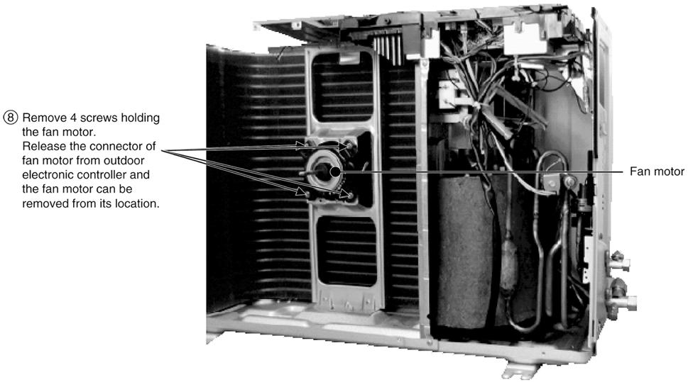
51 14. Remove the Auto Cleaning Complete by releasing the 5 screws. (Fig. 8). For detailed instructions, please refer to 16.2 Filter Cleaning Device Complete Removal Instructions. 15. Remove the Control Board by releasing the screw. (Fig. 9) Fig Pull out the Drain Hose (behind the Discharge Grille) from outlet to remove the Discharge Grille. (Fig. 10) Fig Release the 3 screws Fan Motor Cover. (Fig. 11) 18. By pressing down the hook at the left, you will be able to remove the Fan Motor Cover. (Fig. 11) Fig. 10 Fig
 Reminders:- To reinstall the Fan Motor, please adjust the connector")
 20. Remove the Bearing. (Fig. 13) 21.")

52 19. Remove the screw at the Cross Flow fan. (Fig. 12) Reminders:- To reinstall the Fan Motor, please adjust the connector location is positioned 45 with Fan Motor before fixing Control Board Cover. (Fig. 12) 20. Remove the Bearing. (Fig. 13) 21. Remove the 2 screws at the left of the Evaporator. (Fig. 13) Fig Push up the Evaporator and pull out the Cross Flow Fan from shaft. By then, Fan Motor can be taken out. (Fig. 14) Fig. 13 Fig
 Cutter Switch off the power")

. 5.")
 may drop out while")
53 16.2. Filter Cleaning Device Complete Removal Instructions Tools Required: Screw driver (+ type) Cutter Switch off the power supply and unplug before cleaning or servicing. 1. Remove the front intake grille. 2. Push to remove top intake grille. 3. Release 2 caps and unscrew. 4. Unscrew and then remove the particular piece (right). 5. Unscrew and remove the particular pieces (left and bottom). Caution: The particular piece (bottom) may drop out while removing. 6. Remove terminal cover. 7. Cut the cable tie. 53


54 8. Remove all connectors from the PCB. 9. Remove screws (5 pieces). 10. Lift the filter cleaning device gently to remove. 54

. 3.")
. 5.")
55 16.3. Ventilation Device Removal Instructions 1. Cut the cable tie and remove the flexible hose connector. 2. Unscrew (1 piece). 3. Disconnect the connector. 4. Unscrew (2 pieces). 5. Disconnect the ventilation device from the duct. 6. Remove the ventilation device. 55


56 16.4. Gear Removal Instructions 1. Unscrew (3 pieces). 2. Remove the gear. 3. Disconnect the connector from the gear. 56


57 16.5. Outdoor Propeller Fan and Fan Motor 57
58 58
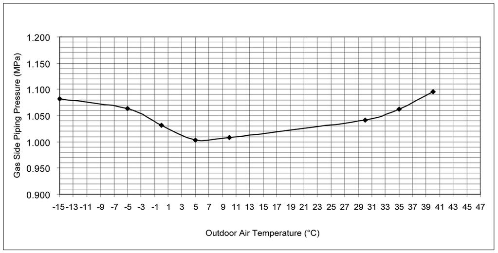
59 17 Technical Data CS-XE9EKE CU-XE9EKE A. Cool: Outdoor Temperature Change Indoor Temp.: 27/19 C Remote Con.: HI FAN, COOL 16 C Comp. Hz: Rated Cooling Voltage: 230 V 59
60 60
Air Conditioner CONTENTS CS-E18EKU CU-E18EKU CS-E21EKU CU-E21EKU. Order No: MAC C1
 Order No: MAC0512115C1 CS-E18EKU CU-E18EKU CS-E21EKU CU-E21EKU Air Conditioner CONTENTS Page Page 1 Safety Precautions 3 2 Specification 5 2.1. CS-E18EKU CU-E18EKU 5 2.2. CS-E21EKU CU-E21EKU 7 3 Location
TABLE OF CONTENTS. Air Conditioner CS-NE7GKE CU-NE7GKE CS-NE9GKE CU-NE9GKE CS-NE12GKE CU-NE12GKE
 Order No. MAC0705021C2 Air Conditioner CS-NE7GKE CU-NE7GKE CS-NE9GKE CU-NE9GKE CS-NE12GKE CU-NE12GKE TABLE OF CONTENTS PAGE 1 Safety Precaution ------------------------------------------------ 2 2 Specifications
TABLE OF CONTENTS. Air Conditioner CS-E24GKES CU-E24GKE CS-E28GKE CU-E28GKE
 Order No. MAC0701008C2 CS-E24GKES CU-E24GKE CS-E28GKE CU-E28GKE Air Conditioner TABLE OF CONTENTS PAGE 1 Safety Precautions----------------------------------------------- 2 2 Specifications -----------------------------------------------------
CU-3E23CBPG, CU- 4E27CBPG,
 Order No. PHAAM0810051C2 Air Conditioner Indoor Unit Outdoor Unit CS-E7JKEW CU-E7JKE CS-E9JKEW CU-E9JKE CS-E12JKEW CU-E12JKE CS-E15JKEW CU-E15JKE CS-E15JKEW CU-E15JKE-1 CS-E7JKEW-3 CU-E7JKE-3 CS-E9JKEW-3
TABLE OF CONTENTS. Air Conditioner CS-MRE12MKE
 Order No. PHAAM1103074C8 Indoor Unit CS-MRE7MKE CS-MRE9MKE CS-MRE12MKE Air Conditioner Outdoor Unit CU-2RE15MBE CU-2RE18MBE TABLE OF CONTENTS PAGE 1 Safety Precautions-----------------------------------------------
AUTO COOL DRY FAN SPEED AIR SWING OFF ON TIMER TIMER OFF/ON FAN SPEED MODE TEMP AIR SWING TIMER ON SET OFF CANCEL AC RC SET CHECK CLOCK RESET
 AUTO COOL DRY MODE TIMER ON OFF TIMER OFF/ON TEMP ON TIMER FAN SPEED AIR SWING SET 1 2 3 FAN SPEED AIR SWING OFF CANCEL AC RC SET CHECK CLOCK RESET Order No: PAPAMY1611008CE Indoor Unit CS-MPS9SKH CS-MPS12SKH
TABLE OF CONTENTS. Air Conditioner. Indoor Unit Outdoor Unit CS-NE9LKE CU-NE9LKE CS-NE12LKE CU-NE12LKE CS-XE9LKE-5 CU-NE9LKE CS-XE12LKE-5 CU-NE12LKE
 Order No. PHAAM1007139C2 Air Conditioner Indoor Unit Outdoor Unit CS-NE9LKE CU-NE9LKE CS-NE12LKE CU-NE12LKE CS-XE9LKE-5 CU-NE9LKE CS-XE12LKE-5 CU-NE12LKE TABLE OF CONTENTS PAGE 1 Safety Precautions-----------------------------------------------
CS-E18NKUA CS-E24NKUA CU-E18NKUA CU-E24NKUA TABLE OF CONTENTS WARNING
 Order No: PAPAMY1204088CE Indoor Unit CS-E18NKUA CS-E24NKUA Outdoor Unit CU-E18NKUA CU-E24NKUA WARNING This service information is designed for experienced repair technicians only and is not designed for
Room Air Conditioner CONTENTS CS-E9BKP CU-E9BKP5 CS-E12BKP CU-E12BKP5. Order No: MAC C2
 Order No: MAC008C Room Air Conditioner CS-E9BKP CU-E9BKP5 CS-EBKP CU-EBKP5 CONTENTS Page Page Features Functions Product Specifications 6 Dimensions 0 5 Refrigeration Cycle Diagram 6 Block Diagram 7 Wiring
CS-RE9JKX-1 CS-RE12JKX-1 CS-RE15JKX-1 CU-RE9JKX-1 CU-RE12JKX-1 CU-RE15JKX-1 TABLE OF CONTENTS WARNING
 Order No: PHA-AG1002007C2 Indoor Unit CS-RE9JKX-1 CS-RE12JKX-1 CS-RE15JKX-1 Outdoor Unit CU-RE9JKX-1 CU-RE12JKX-1 CU-RE15JKX-1 WARNING This service information is designed for experienced repair technicians
CS-UE9PKE CS-UE12PKE CU-UE9PKE CU-UE12PKE TABLE OF CONTENTS WARNING
 Order No: PAPAGZ121215CE Indoor Unit CS-UE9PKE CS-UE12PKE Outdoor Unit CU-UE9PKE CU-UE12PKE WARNING This service information is designed for experienced repair technicians only and is not designed for
CU-YE9MKE CU-YE12MKE CU-YE18MKE CS-YE9MKE CS-YE12MKE CS-YE18MKE TABLE OF CONTENTS WARNING
 Order No: PHA-AG1102003C2 Indoor Unit CS-YE9MKE CS-YE12MKE CS-YE18MKE Outdoor Unit CU-YE9MKE CU-YE12MKE CU-YE18MKE WARNING This service information is designed for experienced repair technicians only and
Destination Europe WARNING
 Order No: PAPAMY1406071CE Indoor Unit CS-E12QD3EAW Outdoor Unit CU-E12QD3EA Destination Europe Please file and use this manual together with the service manual for Model No. CU-2E15PBE CU-2E18PBE CU-3E18PBE
Air Conditioner CONTENTS CS-TE9DKE CU-TE9DKE CS-TE12DKE CU-TE12DKE. Order No. RAC C2
 Order No. RAC0502005C2 Air Conditioner CS-TE9DKE CU-TE9DKE CS-TE12DKE CU-TE12DKE CONTENTS Page Page 1 Features 2 2 Functions 3 2.1. Remote Control 3 2.2. Indoor Unit 4 2.3. Outdoor unit 5 3 Product Specifications
Air-to-Water Heatpump
 Order No. PHAAM1006120C2 Air-to-Water Heatpump Indoor Unit Outdoor Unit WH-SDC07C3E5 WH-UD07CE5-A WH-SDC09C3E5 WH-UD09CE5-A WH-SDC12C6E5 WH-UD12CE5-A WH-SDC14C6E5 WH-UD14CE5-A WH-SDC16C6E5 WH-UD16CE5-A
Air Conditioner CONTENTS CS-V18DKE CU-V18DKE CS-V24DKE CU-V24DKE. Order No. MAC C2
 Order No. MAC0410044C2 CS-V18DKE CU-V18DKE CS-V24DKE CU-V24DKE Air Conditioner CONTENTS Page Page 1 Features 2 2 Functions 3 2.1. Remote Control 3 2.2. Indoor Unit 4 2.3. Outdoor Unit 5 3 Product Specifications
TABLE OF CONTENTS. Air Conditioner
 Order No. MAC0804027A2 Air Conditioner CS-E9GFEW-2 CU-E9GFE-2 CS-E12GFEW-2 CU-E12GFE-2 CS-E18GFEW-2 CU-E18GFE-2 CU-2E15GBE CU-3E18EBE CU-3E23CBPG CU-4E27CBPG Please file and use this manual together with
Air Conditioner CONTENTS CS-E9DKEW CU-E9DKE CS-E12DKEW CU-E12DKE. Order No: MAC C2
 Order No: MAC041064C CS-E9DKEW CU-E9DKE CS-E1DKEW CU-E1DKE Air Conditioner CONTENTS Page Page 1 Features Functions 3.1. Remote Control 3.. Indoor Unit 4.3. Outdoor Unit 6 3 Product Specifications 7 3.1.
CU-S9NKV-7 CU-S12NKV-7 CU-S18NKV-7 CU-S22NKV-7 CS-S9NKV-7 CS-S12NKV-7 CS-S18NKV-7 CS-S22NKV-7 WARNING
 Order No: PAPAMY1206010CE Indoor Unit CS-S9NKV-7 CS-S12NKV-7 CS-S18NKV-7 CS-S22NKV-7 Outdoor Unit CU-S9NKV-7 CU-S12NKV-7 CU-S18NKV-7 CU-S22NKV-7 WARNING This service information is designed for experienced
Room Air Conditioner CONTENTS CS-E18CKE CU-E18CKE CS-E21CKE CU-E21CKE. Order No. MAC C2
 Order No. MAC00801C Room Air Conditioner CS-E18CKE CU-E18CKE CS-E1CKE CU-E1CKE CONTENTS Page Page 1 Features Functions Product Specifications 6 4 Dimensions 10 5 Refrigeration Cycle Diagram 1 6 Block Diagram
Room Air Conditioner CONTENTS CS-PV9CKE CU-PV9CKE CS-PV12CKE CU-PV12CKE
 Order Number: GMAC0311008C2 Room Air Conditioner CS-PV9CKE CU-PV9CKE CS-PV12CKE CU-PV12CKE CONTENTS Page Page 1 Functions 2 2 Product Specifications 5 3 Dimensions 9 4 Refrigeration Cycle Diagram 11 5
INSTALLATION MANUAL. Split-type Air Conditioner (Cooling and Heating) Indoor Unit AQB18J6WC AQB24J2WC. Outdoor Unit UQB18J6WC UQB24J2WC
 Indoor Unit AQB18J6WC AQB24J2WC. Outdoor Unit UQB18J6WC UQB24J2WC") AQB8J6WC_IM_E_25864 2006.4.4 3:29 PM Page 7 INSTALLATION MANUAL Indoor Unit AQB8J6WC AQB24J2WC Outdoor Unit UQB8J6WC UQB24J2WC ENGLISH FRANÇAIS ESPAÑOL Split-type Air Conditioner (Cooling and Heating)
AQB8J6WC_IM_E_25864 2006.4.4 3:29 PM Page 7 INSTALLATION MANUAL Indoor Unit AQB8J6WC AQB24J2WC Outdoor Unit UQB8J6WC UQB24J2WC ENGLISH FRANÇAIS ESPAÑOL Split-type Air Conditioner (Cooling and Heating)
INSTALLATION MANUAL. Split-type Air Conditioner (Cooling and Heating) Outdoor Unit UQB09JJWC UQB12JJWC. Indoor Unit AQB09JJWC AQB12JJWC
 Outdoor Unit UQB09JJWC UQB12JJWC. Indoor Unit AQB09JJWC AQB12JJWC") AQB09JJ6WC_IM_E_2585 2006.4.17 4:26 PM Page 17 INSTALLATION MANUAL Indoor Unit AQB09JJWC AQB12JJWC Outdoor Unit UQB09JJWC UQB12JJWC ENGLISH FRANÇAIS ESPAÑOL Split-type Air Conditioner (Cooling and Heating)
AQB09JJ6WC_IM_E_2585 2006.4.17 4:26 PM Page 17 INSTALLATION MANUAL Indoor Unit AQB09JJWC AQB12JJWC Outdoor Unit UQB09JJWC UQB12JJWC ENGLISH FRANÇAIS ESPAÑOL Split-type Air Conditioner (Cooling and Heating)
Operating Instructions Air Conditioner
 alleru-buster F566894 Operating Instructions Air Conditioner Indoor Unit CS-RE9JKR CS-RE1JKR Outdoor Unit CU-RE9JKR CU-RE1JKR ENGLISH ~ 7 Before operating the unit, read these operating instructions thoroughly
Operating Instructions Air Conditioner
 F566276 Operating Instructions Air Conditioner CS-C45FFH CU-C45FFH ENGLISH Before operating the unit, read these operating instructions thoroughly and keep them for future reference. CONTENTS Safety Precautions...
Air-to-Water Hydromodule + Tank WH-UX12FE5 WH-UD12FE5 WH-UD16FE5. Destination Europe WARNING
 Order : PAPAMY420CE Air-to-Water Hydromodule + Tank Indoor Unit WH-ADC26G6E5 Outdoor Unit WH-UX09FE5 WH-UX2FE5 WH-UD2FE5 WH-UD6FE5 Destination Europe WARNING This service information is designed for experienced
Operating Instructions Air Conditioner
 F566113 Operating Instructions Air Conditioner Indoor Unit CS-E18HKR CS-E1HKR CS-E4HKR CS-E8HKR Outdoor Unit CU-E18HKR CU-E1HKR CU-E4HKR CU-E8HKR Before operating the unit, read these operating instructions
DC INVERTER MULTI-SYSTEM AIR CONDITIONER
 TECHNICAL & SERVICE MANUAL OUTDOOR UNIT : CU-3KE19NBU CU-4KE24NBU CU-4KE31NBU DC INVERTER MULTI-SYSTEM AIR CONDITIONER Capacity at 0V 19,100 BTU/h,200 BTU/h 30,600 BTU/h Outdoor Model No. CU-3KE19NBU CU-4KE24NBU
Operating Instructions Air Conditioner
 F56690 Operating Instructions Air Conditioner Indoor Unit CS-S9JKR CS-S1JKR Outdoor Unit CU-S9JKR CU-S1JKR Before operating the unit, read these operating instructions thoroughly and keep them for future
CU-RE18RKE CU-RE24RKE CS-RE18RKEW CS-RE24RKEW. Destination Europe L.America Turkey WARNING
 Order No: PAPAMY502047CE Indoor Unit CS-RE8RKEW CS-RE24RKEW Outdoor Unit CU-RE8RKE CU-RE24RKE Destination Europe L.America Turkey WARNING This service information is designed for experienced repair technicians
Operating Instructions Air Conditioner
 F56579 Operating Instructions Air Conditioner Indoor Unit Outdoor Unit CS-E18GKR CS-E1GKR CS-E4GKR CS-E8GKR CU-E18GKR CU-E1GKR CU-E4GKR CU-E8GKR Before operating the unit, read these operating instructions
Operating Instructions
 Operating Instructions Air Conditioner Model No. Indoor Unit CS-PC9QKH CS-PC12QKH CS-PC18QKH CS-PC24QKH CS-PC28QKH Outdoor Unit CU-PC9QKH CU-PC12QKH CU-PC18QKH CU-PC24QKH CU-PC28QKH Operating Instructions
AUT O HE AT COOL DRY FAN SPEE D AIR SW ING OFF/ON MODE TEMP AIR SW ING POWERFUL/ QUIET TIMER ON SET OFF CANCEL SET CHECK CLOCK RESET WARNING
 AUT O HE AT COOL DRY POWERFUL/ QUIET FAN SPEE D AC AIR SW ING SET CHECK CLOCK RESET FAN SPEED AIR SW ING RC Order No: PAPAMY502046CE Indoor Unit CS-RE9RKEW CS-RE2RKEW CS-RE5RKEW Outdoor Unit CU-RE9RKE
YC ON-OFF SERIES. Service Manual
 YC ON-OFF SERIES Service Manual CONTENTS 1. Precaution... 3 1.1 Safety Precaution... 3 1.2 Warning... 3 2. Model Lists... 6 3. Dimension... 7 3.1 Indoor Unit... 7 3.2 Outdoor Unit... 11 4. Refrigerant
IMPORTANT SAFETY NOTICE
 Order No: PAPAMY703052CE Indoor Unit CS-TE20TKEW CS-TE25TKEW CS-TE35TKEW CS-TE42TKEW Outdoor Unit CU-TE20TKE CU-TE25TKE CU-TE35TKE CU-TE42TKE Destination Europe Turkey Please file and use this manual together
SINGLE - ZONE Ductless Split System Heat Pumps Installation, Operation & Maintenance Manual
 Presents SINGLE - ZONE Ductless Split System Heat Pumps Installation, Operation & Maintenance Manual 9k,12k 18k 24k, 30k, 36k ECR International, Inc. 2201 Dwyer Avenue, Utica NY 13501 Phone: 800.325.5479
INSTALLATION MANUAL COMFORT...BUILT TO LAST. 9,000, 12,000 and 18,000 BTU SINGLE-ZONE DUCTLESS MINI-SPLIT SYSTEM Heat Pump
 COMFORT...BUILT TO LAST 9,000, 12,000 and 18,000 BTU SINGLE-ZONE DUCTLESS MINI-SPLIT SYSTEM Heat Pump INSTALLATION MANUAL INDOOR UNIT: 1PAMSH09-SZW-14.5 1PAMSH09-SZW-15 1PAMSH12-SZW-15 1PAMSH18-SZW-15
Westinghouse. Split System Inverter Series. Service Manual
 Westinghouse Split System Inverter Series Service Manual Model: WIWPK/WCHPK Range: 2.6kw 7.6kw CONTENTS 1. Precaution... 1 1.1 Safety Precaution... 1 1.2 Warning... 1 2. Function... 5 3. Dimension... 6
Installation Instructions
 40MAQ High Wall Ductless Split System Sizes 09 to 36 Installation Instructions NOTE: Read the entire instruction manual before starting the installation TABLE OF CONTENTS PAGE SAFETY CONSIDERATIONS 2 PARTS
Air Conditioner CONTENTS
 ORDER NO. MAC0509068C2 Air Conditioner CS-F24DD1E5 CU-B24DBE5 CS-F28DD1E5 CU-B28DBE5 CS-F28DD1E5 CU-B28DBE8 CS-F34DD1E5 CU-B34DBE5 CS-F34DD1E5 CU-B34DBE8 CS-F43DD1E5 CU-B43DBE8 CS-F50DD1E5 CU-B50DBE8 CONTENTS
AOYG18LFC OUTDOOR UNIT INSTALLATION MANUAL INSTALLATION MANUAL. For authorized service personnel only. PART NO
 AOYG8LFC OUTDOOR UNIT INSTALLATION MANUAL INSTALLATION MANUAL For authorized service personnel only. English PART NO. 93778639 93778639_IM.indb /20/20 6:07:25 PM AIR CONDITIONER OUTDOOR UNIT INSTALLATION
Inverter Split-type Room Air Conditioner
 OWNER S MANUAL Inverter Split-type Room Air Conditioner Please read the operating instructions and safety precautions carefully and thoroughly before installing and operating your room air conditioner.
Split-type Air-Conditioner INSTALLATION MANUAL CONTENTS FOR INSTALLER MXZ-3B54VA MXZ-4B71VA. English
 Split-type Air-Conditioner MXZ-3B54VA MXZ-4B71VA INSTALLATION MANUAL English Refer to the installation manual of each indoor unit for indoor unit installation. IMPORTANT NOTES TO COMPLY WITH THE REQUIREMENTS
SERVICE MANUAL SPLIT WALL-MOUNTED TYPE MODELS MWCOHC30S/MRCOHC30AS MWCOHC36S/MRCOHC36AS
 SERVICE MANUAL SPLIT WALL-MOUNTED TYPE MODELS MWCOHC30S/MRCOHC30AS MWCOHC36S/MRCOHC36AS CONTENTS 1. Precaution... 1 1.1 Safety Precaution... 1 1.2 Warning... 1 2. Function... 6 3. Dimension... 7 3.1 Indoor
CONTENTS INSTALLATION MANUAL HFC FOR INSTALLER R410A. utilized 1. THE FOLLOWING SHOULD ALWAYS BE OBSERVED FOR SAFETY... 2
 SPLIT-TYPE AIR CONDITIONER CONTENTS INSTALLATION MANUAL 1. THE FOLLOWING SHOULD ALWAYS BE OBSERVED FOR SAFETY... 2 Model MXZ-A26/32WV HFC utilized R410A 2. INSTALLATION DIAGRAM & ACCESSORIES... 2 3. SELECTING
[FLARE CONNECTION TYPE] ATTENTION
![[FLARE CONNECTION TYPE] ATTENTION](/thumbs/88/117511702.jpg "[FLARE CONNECTION TYPE] ATTENTION") SPLIT-TYPE AIR CONDITIONERS Model MXZ-2A20NA [FLARE CONNECTION TYPE] HFC utilized R410A INSTALLATION MANUAL ATTENTION This manual mentions how to install only the outdoor unit, MXZ-2A20NA. As for the way
SPLIT-TYPE AIR CONDITIONERS Model MXZ-2A20NA [FLARE CONNECTION TYPE] HFC utilized R410A INSTALLATION MANUAL ATTENTION This manual mentions how to install only the outdoor unit, MXZ-2A20NA. As for the way
Operating Instructions
 Operating Instructions Air Conditioner Model No. Indoor Unit CS-E12QD3RW CS-E18QD3RW Single Split Outdoor Unit CU-E12QD3R CU-E18QD3R Multi Split Outdoor Unit CU-4E23QBR CU-4E27QBR CU-5E34QBR Operating
Split-type Air-Conditioner
 Split-type Air-Conditioner MXZ-2D52VA Installation Manual For INSTALLER This manual only describes the installation of outdoor unit. When installing the indoor unit, refer to the installation manual of
DC INVERTER MULTI-SYSTEM AIR CONDITIONER
 TECHNICAL & SERVICE MANUAL OUTDOOR UNIT : CLM97 CLM7 CLM7 FILE NO. Destination: North America DC INVERTER MULTI-SYSTEM AIR CONDITIONER Capacity at 0V 9,700 BTU/h,00 BTU/h 0,600 BTU/h Outdoor Model No.
1. BEFORE INSTALLATION
 ENGLISH SPLIT-TYPE AIR CONDITIONERS INSTALLATION MANUAL MSZ-D30/36NA MSY-D30/36NA JG79A061H09 Phillips screwdriver Level Scale Utility knife or scissors 3 in. (75 mm) hole saw Torque wrench Wrench (or
Installation Instructions
 40MBFQ Floor Console Ductless System Sizes 09 to 58 Installation Instructions TABLE OF CONTENTS PAGE SAFETY CONSIDERATIONS... 2 PARTS LIST... 3 SYSTEM REQUIREMENTS... 4 WIRING... 4 DIMENSIONS... 5 CLEARANCES...
Installation and Operation Manual. CMA12SB-0 Series. Horizontal/Side Discharge Condensing Units
 Installation and Operation Manual CMA12SB-0 Series Horizontal/Side Discharge Condensing Units 517.787.2100 www.marsdelivers.com www.heatcontroller.com Heat Controller CONTENTS PAGE 1. PRES... 1 2. INSTALLATION
1. BEFORE INSTALLATION
 ENGLISH SPLIT-TYPE AIR CONDITIONERS INSTALLATION MANUAL Model names are indicated in 1-3. JG79A145H05 Phillips screwdriver Level Scale Utility knife or scissors 75 mm hole saw Torque wrench Wrench (or
Air-to-Water Hydromodule + Tank WH-UD05HE5-1 WH-UD07HE5-1 WH-UD09HE5-1. Destination Europe Turkey
 Order : PAPAMY1607068CE Air-to-Water Hydromodule + Tank Indoor Unit WH-ADC0309H3E5 Outdoor Unit WH-UD03HE5-1 WH-UD05HE5-1 WH-UD07HE5-1 WH-UD09HE5-1 Destination Europe Turkey WARNING This service information
Split-type Air-Conditioner
 Split-type Air-Conditioner MXZ-2C52VA Installation Manual For INSTALLER This manual only describes the installation of outdoor unit. When installing the indoor unit, refer to the installation manual of
TECHNICAL & SERVICE MANUAL WINDOW TYPE AIR CONDITIONER SA 183A FILE NO. SA 183A REFERENCE NO. SM Destination Australia SA-183A
 TECHNICAL & SERVICE MANUAL SA 183A FILE NO. WINDOW TYPE AIR CONDITIONER Model No. Product Code No. SA-183A 1 851 006 96 Destination Australia SA 183A REFERENCE NO. SM700514 IMPORTANT! Please Read Before
SiBE04-808_C. Service Manual. Inverter Pair Wall Mounted Type G-Series. [Applied Models] Inverter Pair : Cooling Only Inverter Pair : Heat Pump
![SiBE04-808_C. Service Manual. Inverter Pair Wall Mounted Type G-Series. [Applied Models] Inverter Pair : Cooling Only Inverter Pair : Heat Pump](/thumbs/88/114609417.jpg "SiBE04-808_C. Service Manual. Inverter Pair Wall Mounted Type G-Series. [Applied Models] Inverter Pair : Cooling Only Inverter Pair : Heat Pump") Service Manual Inverter Pair Wall Mounted Type G-Series [Applied Models] Inverter Pair : Cooling Only Inverter Pair : Heat Pump Inverter Pair Wall Mounted Type G-Series Cooling Only Indoor Unit FTXS20G2V1B
Service Manual Inverter Pair Wall Mounted Type G-Series [Applied Models] Inverter Pair : Cooling Only Inverter Pair : Heat Pump Inverter Pair Wall Mounted Type G-Series Cooling Only Indoor Unit FTXS20G2V1B
DC INVERTER SPLIT SYSTEM AIR CONDITIONER
 AIR CONDITIONER TECHNICAL & SERVICE MANUAL KS1872 + C1872 + CL1872 KS2472 + C2472 + CL2472 FILE NO. Destination: North America DC INVERTER SPLIT SYSTEM AIR CONDITIONER Indoor Model No. KS1872 KS2472 Product
SPLIT-TYPE ROOM AIR CONDITIONER
 Before using your air conditioner, please read this manual carefully and keep it for future reference SPLIT-TYPE ROOM AIR CONDITIONER Please read this installation manual completely before installing the
MXZ-4B80VA MXZ-5B100VA INSTALLATION MANUAL
 Split-type Air-Conditioner MXZ-4B80VA MXZ-5B100VA INSTALLATION MANUAL Refer to the installation manual of each indoor unit for indoor unit installation. English Deutsch Français Nederlands Español Italiano
1. BEFORE INSTALLATION
 ENGLISH SPLIT-TYPE AIR CONDITIONERS INSTALLATION MANUAL MSZ-D30/36NA MSY-D30/36NA JG79A061H01 Phillips screwdriver Level Scale Utility knife or scissors 3 in. (75 mm) hole saw Torque wrench Wrench (or
1. BEFORE INSTALLATION
 ENGLISH SPLIT-TYPE AIR CONDITIONERS INSTALLATION MANUAL MSZ-FH09/12/15NA JG79A805H01 When installing multi units, refer to the installation manual of the multi unit for outdoor unit installation. Phillips
F SERIES ON-OFF SERIES. Service Manual 2016
 F SERIES ON-OFF SERIES Service Manual 2016 CONTENTS 1. Precaution... 3 1.1 Safety Precaution... 3 1.2 Warning... 3 2. Function... 6 3. Dimension... 7 3.1 Indoor Unit... 7 3.2 Outdoor Unit... 9 4. Refrigerant
WARNING IMPORTANT SAFETY NOTICE
 Order No: PAPAMY8020CE Indoor Unit CS-FZ25UKE CS-FZ35UKE CS-FZ50UKE CS-FZ60UKE Outdoor Unit CU-FZ25UKE CU-FZ35UKE CU-FZ50UKE CU-FZ60UKE Destination Europe Turkey FAN SPEED FAN SPEED WARNING This service
INVERTER SPLIT - TYPE
 INVERTER SPLIT - TYPE ISSUE No 2 DATE 04/09/08 P/No 2020323A2868 CONTENTS SAFETY PRECAUTIONS Warning 2 Operating temperature 2 BEFORE INSTALLATION Tools needed for installation 3 Items required for installing
Service Manual. Room Air Conditioner Split Wall-Mounted Type. Applies to: HSG-09HRN1 HSG-12HRN1 HSG-18HRN1 HSG-24HRN1
 Service Manual Room Air Conditioner Split Wall-Mounted Type Applies to: HSG-09CRN1 HSG-12CRN1 HSG-18CRN1 HSG-24CRN1 HSG-09HRN1 HSG-12HRN1 HSG-18HRN1 HSG-24HRN1 NOTE: Please read this first before servicing
FLOOR-STANDING TYPE AIR CONDITIONER INSTALLATION MANUAL
 FLOOR-STANDING TYPE AIR CONDITIONER INSTALLATION MANUAL CONTENTS SAFETY PRECAUTIONS Warning... Caution... INSTALLATION INSTRUCTIONS Accessories...;...3 Selecting installation place...4 PIPE CONNECTION
1. BEFORE INSTALLATION
 ENGLISH SPLIT-TYPE AIR CONDITIONERS INSTALLATION MANUAL REFRIGERANT JG79B528H01 Model names are indicated in 1-3. Phillips screwdriver Level Scale Utility knife or scissors 75 mm hole saw Torque wrench
Room Air Conditioner Service and Parts Manual
 Cool Dry Temp Mode Room Air Conditioner Service and Parts Manual F Fan Speed hr Timer 0n 0ff Money Saver Fan Only Auto Swing Power CP06 CP08 93011401_01 CONTENTS 1. PREFACE 1.1 SAFETY PRECAUTIONS...2 1.2
Installation Manual. KS Series KS09 KS12 KS18 KS24 KS28. J3387_Kaden_Installer_Manual_ indd 1
 Wall Mounted AIR CONDITIONER Installation Manual KS Series KS09 KS12 KS18 KS24 KS28 J3387_Kaden_Installer_Manual_050917.indd 1 5/09/2017 9:07 AM J3387_Kaden_Installer_Manual_050917.indd 2 5/09/2017 9:07
SERVICE MANUAL MUY-GL24NA - U1. No. OBH733. Models HFC. Revision B: REVISED EDITION-B R410A
 Revision B: MUZ-GL09NA- U8 and MUZ-GL09NAH- U8 have been added. Please void OBH733 REVISED EDITION-A. OUTDOOR INDOOR UNIT UNIT SERVICE MANUAL HFC utilized R410A. OBH733 REVISED EDITION-B Models MUZ-GL09NA
Installation Instructions
 40MBFQ Floor Console Ductless System Sizes 09 to 12 Installation Instructions TABLE OF CONTENTS PAGE SAFETY CONSIDERATIONS... 2 PARTS LIST... 3 SYSTEM REQUIREMENTS... 4 DIMENSIONS... 5 CLEARANCES... 5
1. BEFORE INSTALLATION
 ENGLISH SPLIT-TYPE AIR CONDITIONERS INSTALLATION MANUAL REFRIGERANT JG79B530H01 Model names are indicated in 1-3. Phillips screwdriver Level Scale Utility knife or scissors 75 mm hole saw Torque wrench
DUCTED AIR CONDITIONER. Owner s Manual. KD Series KD24. Kaden Owner s Manual 1
 DUCTED AIR CONDITIONER Owner s Manual KD Series KD24 Kaden Owner s Manual 1 Table of Contents 1. Safety Precautions 4 2. Indoor Unit Parts and Major Functions 6 3. Care and Maintenance 8 4. Troubleshooting
0RGHOV,QGRRU 8QLW MWM36Y3J 2XWGRRU 8QLW MRM36Y3J 11
 MWM36Y3J MRM36Y3J 11 Content Operation Notices Precautions...1 Parts name...2 Screen Operation Guide Buttons on remote controller...3 Introduction for icons on display screen...3 Introduction for buttons
Choosing the installation site. Installation. 07 Choosing the installation site
 Installation Installation warnings: 1. Carefully read the installation manual before beginning. 2. Follow each step as shown. 3. Observe all local, state, and national electrical codes and by qualified,
TECHNICAL & SERVICE MANUAL WINDOW TYPE AIR CONDITIONER SA 123A FILE NO. SA 123A REFERENCE NO. SM700513
 TECHNICAL & SERVICE MANUAL SA 123A FILE NO. WINDOW TYPE AIR CONDITIONER Model No. Product Code No. Destination SA-123A 1 851 006 95 Australia SA 123A REFERENCE NO. SM700513 IMPORTANT! Please Read Before
Operating Instructions Air Conditioner
 Operating Instructions Air Conditioner Model No. Indoor Unit CS-EGFEW CS-E8GFEW Outdoor Unit CU-EGFR CU-E8GFR ENGLISH ~ Before operating the unit, read these operating instructions thoroughly and keep
SERVICE MANUAL MUFZ-KJ50VE - E1, E2, ER1, ER2, ET1, ET2 MUFZ-KJ35VE OUTDOOR UNIT. No. OBH667. Models HFC
 Revision D: MUFZ-KJ25VE - E2, ER2, ET2, MUFZ- KJ35VE - E2, ER2, ET2 and MUFZ- KJ50VE - E2, ER2, ET2 have been added. Please void OBH667 REVISED EDITION-C. OUTDOOR UNIT SERVICE MANUAL HFC utilized R410A.
1. BEFORE INSTALLATION
 ENGLISH SPLIT-TYPE AIR CONDITIONERS INSTALLATION MANUAL REFRIGERANT JG79Y335H01 Model names are indicated in 1-3. When installing multi units, refer to the installation manual of the multi unit for outdoor
Content Precaution...2 Function...3 Dimension...5 Refrigerant cycle diagram...7 Operation limits...8 Wiring diagram...9 Installation details...
 Cover Content Content 1. Precaution...2 1.1 Safety Precaution...2 1.2 Warning...2 2. Function...3 3. Dimension...5 3.1 Indoor unit...5 3.2 Outdoor unit...5 4. Refrigerant cycle diagram...7 5. Operation
AY-AP09DJ SPLIT TYPE ROOM AIR CONDITIONER OPERATION MANUAL AE-A09DJ AY-AP09DJ OUTDOOR UNIT INDOOR UNIT
 R AY-AP09DJ SPLIT TYPE ROOM AIR CONDITIONER OPERATION MANUAL INDOOR UNIT AY-AP09DJ OUTDOOR UNIT AE-A09DJ ENGLISH Thank you for purchasing a SHARP air conditioner. Please read this manual carefully before
Owner s Manual Super-Slim Four-Way Cassette
 CASSETTE- TYPE AIR CONDITIONER Owner s Manual Super-Slim Four-Way Cassette IMPORTANT NOTE: Read this manual carefully before installing or operating your new air conditioning unit. Make sure to save this
SERVICE MANUAL. No. OBH747 REVISED EDITION-A. Models HFC
 Revision A: MUZ-HM09/12NA- U8, MUZ-HM09/12NA2- U8, MUZ-HM15/18NA- U1, MUZ-HM15/18NA2- U1 and MUZ-HM24NA2- U1 have been added. Please void OBH747. OUTDOOR INDOOR UNIT UNIT SERVICE MANUAL HFC utilized R410A.
INSTALLATION MANUAL SPLIT TYPE ROOM AIR CONDITIONER (PART NO )
") SPLIT TYPE ROOM AIR CONDITIONER INSTALLATION MANUAL (PART NO. 9312791019-01) This air conditioner uses new refrigerant HFC (R410A). The basic installation work procedures are the same as conventional refrigerant
SPLIT TYPE ROOM AIR CONDITIONER INSTALLATION MANUAL (PART NO. 9312791019-01) This air conditioner uses new refrigerant HFC (R410A). The basic installation work procedures are the same as conventional refrigerant
NOTE: All the illustrations in this manual are for explanation purposes only. Your air conditioner may be slightly different.
 RADS-51J RADS-61J Owner s Manual Room Air Conditioner with R-410A Heat Controller, Inc. 15 16 Contact an authorized service technician for repair or maintenance of this unit. Contact an authorized installer
KSD-35 DR11 KUE-35 DVN11
 FLOOR-STANDING TYPE AIR CONDITIONER Owner s Manual Floor-Standing Type KSD-35 DR11 KUE-35 DVN11 IMPORTANT NOTE: Read this manual carefully before installing or operating your new air conditioning unit.
DAIKIN AIR CONDITIONER
 3P226011-1A M07B242A DAIKIN AIR CONDITIONER Two-dimensional bar code is a code for manufacturing. Safety Precautions (1) Read these Safety Precautions carefully to ensure correct installation. This manual
WINDOW TYPE ROOM AIR CONDITIONER OPERATION AND INSTALLATION MANUAL
 MODEL RA-0LDF RA-3LDF WINDOW TYPE ROOM AIR CONDITIONER OPERATION AND INSTALLATION MANUAL AIR DEFLECTORS VERTICAL DEFLECTORS Vertical de ectors at both sides of outlets can be set to either auto-swing or
FLOOR-STANDING SPLIT TYPE ROOM AIR CONDITIONER
 Before using your air conditioner, please read this manual carefully and keep it for future reference. FLOOR-STANDING SPLIT TYPE ROOM AIR CONDITIONER Please read this installation manual completely before
Split-type Air-Conditioner
 Split-type Air-Conditioner MXZ-2E52VAD MXZ-3E54VAD MXZ-4E71VAD Installation Manual For INSTALLER This manual only describes the installation of outdoor unit. When installing the indoor unit, refer to the
1. BEFORE INSTALLATION
 ENGLISH SPLIT-TYPE AIR CONDITIONERS INSTALLATION MANUAL JG79A191H07 MSZ-GE06/09/12/15/18NA MSY-GE09/12/15/18NA When installing multi units, refer to the installation manual of the multi unit for outdoor
Service Manual. Inverter Pair Floor / Ceiling Suspended Dual Type BA-Series. SiBE05-722_C
 Service Manual Inverter Pair Floor / Ceiling Suspended Dual Type BA-Series [Applied Models] Inverter Pair : Cooling Only Inverter Pair : Heat Pump Inverter Pair Floor / Ceiling Suspended Dual Type BA-Series
TABLE OF CONTENTS. NOTE: Read the entire instruction manual before starting the installation. TROUBLESHOOTING... 13
 R 410A Duct Free Split System Air Conditioner and Heat Pump Product Family: DFS4(A/H) System, DFC4(A/H)3 Outdoor, DFF4(A/H)H Indoor NOTE: Read the entire instruction manual before starting the installation.
VMI-1102-A SERVICE MANUAL AIRCONDITIONER DC INVERTER MULTI TYPE MSV1I-09HRDN1-M TAS-09MVHN TAS-12MVHN INDOOR VERTU DC INVERTER MULTI SERIES
 VMI-1102-A SERVICE MANUAL AIRCONDITIONER DC INVERTER MULTI TYPE MSV1I-09HRDN1-M TAS-09MVHN TAS-12MVHN INDOOR VERTU DC INVERTER MULTI SERIES CONTENTS 1. Precaution... 1 1.1 Safety Precaution...1 1.2 Warning...1
SERVICE MANUAL OUTDOOR UNIT MUZ-FH06NAH MUZ-FH09NAH MUZ-FH06NA MUZ-FH09NA MUZ-FH09NA - 1 MUZ-FH09NAH - 1 MUZ-FH12NA MUZ-FH12NAH
 Revision D: Capacity corrections have been corrected [7-1. 2), 3)]. OBH684 REVISED EDITION-C is void. OUTDOOR UNIT SERVICE MANUAL HFC utilized R410A. OBH684 REVISED EDITION-D Models MUZ-FH06NA MUZ-FH09NA
SERVICE MANUAL MUZ-FH25VE MUZ-FH35VE MUZ-FH50VE OUTDOOR UNIT. No. OBH624. Models HFC. Revision A: MUZ-FH50VE- E1 has been added. Please void OBH624.
 SPLIT-TYPE AIR CONDITIONERS Revision A: MUZ-FH50VE- E1 has been added. Please void OBH624. OUTDOOR UNIT SERVICE MANUAL HFC utilized R410A. OBH624 REVISED EDITION-A Models MUZ-FH25VE MUZ-FH35VE MUZ-FH50VE
Split Air Conditioner. Model: WMI09MH16S WMI12MH16S WMI18MH16S
 Split Air Conditioner Model: WMI09MH16S WMI12MH16S WMI18MH16S Thank you for choosing our product. For proper operation, please read and keep this manual carefully. Content Operation Notices Precautions...1
Installation Instructions
 40MAQ High Wall Ductless System Sizes 09 to 36 Installation Instructions NOTES: Read the entire instruction manual before starting the installation. Images are for illustration purposes only. Actual models
TECHNICAL DATA & SERVICE MANUAL
 TECHNICAL DATA & SERVICE MANUAL OUTDOOR UNIT: GRF188R5TAA GRF228R5TAA GRF228R7TAA SPLIT SYSTEM AIR CONDITIONER Model No. Product Code No. GRF188R5TAA 38.7107.083 GRF228R5TAA 38.7107.084 GRF228R7TAA 38.7107.085