REFRIGERATOR SIDE BY SIDE TYPE CONTENTS REFRIGERATOR MODEL NAME : RH22H9010SR RH29H9000SR MODEL CODE : RH22H9010SR/AA RH29H9000SR/AA
|
|
|
- Katherine Stephens
- 5 years ago
- Views:
Transcription


1 REFRIGERATOR SIDE BY SIDE TYPE MODEL NAME : RH22H9010SR RH29H9000SR MODEL CODE : RH22H9010SR/AA RH29H9000SR/AA REFRIGERATOR CONTENTS 1. PRECAUTIONS(SAFETY WARNINGS) 5 2. PRODUCT SPECIFICATIONS 8 3. DISASSEMBLY AND REASSEMBLY TROUBLESHOOTING PCB DIAGRAM WIRING DIAGRAM BLOCK DIAGRAM MODEL CODE TABLE 83 RH22H**/RH29H**
2 WARNING IMPORTANT SAFETY TICE The service guide is for service men with adequate backgrounds of electrical, electronic, and mechanical experience. Any attempt to repair a major appliance may result in personal injury and property damage. The manufacturer or dealer cannot be responsible for the interpretation of this information. SAMSUNG ELECTRONICS AMERICA, INC. Technical Service Guide Copyright 2011 All rights reserved. This service guide may not be reproduced in whole or in part in any form without written permission from the SAMSUNG ELECTRONICS Company.
3 Contents 1. PRECAUTIONS (SAFETY WARNINGS) PRODUCT SPECIFICATIONS Introduction of Main Function Model Specification Basic Specification Electric Parts Specification Electric Component Model Inform For E-Cost (Model Code, introduction application date, Weight Inform) Dimensions (mm/inch) Optional Material Specification DISASSEMBLY & REASSEMBLY PRECAUTION Interior-Fridge Multi Duct-Fridge Water Filter (Assembly & Disassembly) Case Water Filter Cover-Display & Water-Dispenser Water-Dispenser Interior-Freezer Evaporator Cover-Freezer Multi Duct (Freezer) Deodorizer Assembly Hinge-Up Disassembling (Freezing Compartment) Assembly Hinge-Up Disassembling (Show Case of Cold Compartment) Assembly Hinge-Up Disassembling (Cold Compartment) Assembly Locker Disassembling (Cold Compartment) Evaporator Main PCB and Inverter PCB Disassembling (whole) Disassemble the WIFI module COMP Cooling Fan Replacing COMP Cooling Fan Replacing For E-cost model COMP Cooling Fan Motor Replacing Relay Protector O/L disassembling (Whole) Step Valve Disassembling (whole) Ice Maker Compartment Auger-Motor Disassembling the internal handle Disassembling the external handle TROUBLESHOOTING Function for failure diagnosis Diagnostic method according to the trouble symptom(flow Chart) PCB DIAGRAM PBA Layout with part position PBA Layout with part position (Inverter Board)... 77
4 Contents 5-3. Connector Layout with part position (Main Board) Connector Layout with part position (Inverter Board) Wiring Diagram Model : RH22*/RH29* Block Diagram Whole block diagram Inverter Block Diagram Model code table MODEL : RH22* MODEL : RH29* MODEL ( E-COST)... 85
5 1. PRECAUTIONS (SAFETY WARNINGS) Unplug the appliance before the changing or repairing the electric parts. Use rated electronic Control equipment. Make sure to check out ModeL name, Rated voltage, Rated current, Operation Temp, etc. Upon repair, make sure that harnesses are not to be water-penetrated and are bundled tight. Should not be detached by a certain amount of external force. Upon repair, completely remove dust or other foreign substances from housing, harness, connector, etc. To prevent fire by tracking, short, etc. Check out whether water has penetrated into the electronic Control system. If there is any kind of trace, take necessary measures such as related component change, insulation tapping, etc. After repair, check out the assembled state of parts. It should be the same as the previous state. Check out the surrounding conditions. Change the location, if the fridge is located at humid, wet places or the installed state is unstable. In order to reduce the risk of electric shock the appliance must be properly grounded. Do not allow consumers to overload a certain outlet. Check out whether the power cord or the outlet is broken, squeezed, chopped off or heatdeformed. Repair or replace the defective power cord/outlet immediately. Make sure the power cord is not punctuated or stomped down. Do not allow consumers to keep food frayed or place bottles in the Freezer Room. Do not allow consumers to repair the fridge by themselves. Do not allow consumers to keep things except for food. Pharmaceutical, Chemical substances : These are not possible to be fine- Controlled with a consumer fridge. Flammable material (alcohol, benzene, ether, LPG, etc) : possibility of explosion. 5
6 PRECAUTIONS(SAFETY WARNINGS) Read all instructions before repairing the product and follow the instructions in order to prevent danger or property damage. CAUTION/WARNING SYMBOLS DISPLAYED Warning Indicates that a danger of death or serious injury exists. SYMBOLS means Prohibited. means Do not disassemble. means No contact. Caution Indicates that a risk of personal injury or material damage exists. means Warning or Caution. means Unplug the unit before preforming service means Earth or Ground. Warning & Caution Plug out to exchange the interior lamp. It may cause electric shock. Use the rated components on the replacement. Check the correct model, rated voltage, rated current, operating temperature and so on. On repair, make sure that the wires such as harness are bundled tightly. Bundle tightly wires in order not to be detached by the external force and then not to be wetted. Rated components Unplug On repair, remove completely dust or other things of housing parts, harness parts, and check parts. Cleaning may prevent the possible fire by tracking or short. After repair, check the assembled state of components. It must be in the same assembled state when compared with the state before disassembly. Check if there is any trace indicating the permeation of water. If there is that kind of trace, change the related components or do the necessary treatment such as taping using the insulating tape. Earth 6
7 PRECAUTIONS(SAFETY WARNINGS) Please let users know following warnings & cautions in detail. Warning & Caution Do not allow users to put bottles or kinds of glass in the freezer. Freezing of the contents may inflict a wound. Do not allow users to store narrow and lengthy bottles or foods in a small multi-purpose room. It may hurt you when refrigerator door is opened and closed resulting in falling stuff down. Do not allow users to store pharmaceutical products, scientific materials, etc., in the refrigerator. The products which need precise temperature control should not be stored in the refrigerator. Prohibited Prohibited Prohibited Do not allow users to plug several appliances into the same power receptable. May cause abnormal generation of heat or fire. Do not allow users to disassemble, repair or alter. It may cause fire or abnormal operation which leads to injury. Do not allow users to bend the power cord with excessive force or do not have the power cord pressed by heavy article. May cause fire. Prohibited Do not disassemble Do not allow users to store articles on the product. Opening or closing the door may cause things to fall down, with may inflict a wound. Do not allow users to install the refrigerator in the wet place or the place where water splashes. Deterioration of insulation of electric parts may cause electric shock or fire. In order to reduce the risk of electric shock the appliance must be properly grounded. Prohibited Earth CAUTION When installing, servicing or cleaning behind the refrigerator, be sure to pull the unit straight out and push back in straight after finishing. 7
8 2. PRODUCT SPECIFICATIONS 2-1. Introduction of Main Function Model Specification Basic Specification Electric Parts Specification Electric Component Model Inform For E-Cost (Model Code, introduction application date, Weight Inform) Dimensions (mm/inch) Optional Material Specification


9 PRODUCT SPECIFICATIONS 2-1. Introduction of Main Function Larger Capacity The Samsung Side by side Refrigerator has plenty of space for all your groceries, beverages, frozen foods and leftovers. It s the perfect size for any occasion - holiday celebration, family reunion or Super Bowl party. Clearview In-door ice system Located directly on the freezer door, the icemaker is easier to use and doesn t take up valuable shelf space. The seethrough glass also lets you check on the amount of ice available at a glance Surround Multi Air Outlets Cooling air flows out through multiple outlets in every shelf level. This provides even cooling throughout the refrigerator, and quickly returns back to temperature when the door has been opened. So it maintains an ideal temperature to keep your food fresh longer. LED Lighting This space-saving LED fixture illuminates every corner of the fridge, so things are easier to find. Also LED emits less heat than conventional bulb lighting, affecting less damage to the temperature management. 9
10 PRODUCT SPECIFICATIONS 2-2. Model Specification TE The characteristics of your appliance may differ slightly from those described in this manual. - Key features of your new refrigerator Your Samsung Side-By-Side Refrigerator comes equipped with many space-saving, innovative storage and energy-efficient features. Multi Airflow Provides even cooling throughout the refrigerator to maintain optimal temperatures to keep food fresh. LED Lighting See everything in a new light with LED tower lighting. Clear View Icemaker The Icemaker is located in the freezer door, this ensures that all the shelf space can be fully utilized. Ice cubes are quickly produced and the clear ice bucket lets you easily see the amount of ice cubes produced. Premium Design Ice & Water Dispenser Quick and easy access to filtered water and cubed/crushed ice at your fingertips with the external dispenser. E-smart function The E- Smart function enables you to control and monitor your E-Smart refrigerator remotely for convenient use. And E-smart refrigerator is able to save the energy when it operates in SMART GRID (Demand Response)model. 10
11 PRODUCT SPECIFICATIONS 2-3. Basic Specification ITEM Specification Model RH22H90** RH29H90** image Gross capacity (LT) 21.5 cu.ft 28.5 cu.ft Valid net capacity Freezing compartment (LT) 7.2 cu.ft 10.1 cu.ft Cold compartment (LT) 14.3 cu.ft 18.4 cu.ft Dimensions (width x depth x height) Dimensions of package (width x depth x height) 912 x 721 x 1774 (35 7/8"x 28 1/4"x 69 6/8") 972 x 820 x 1909 (38 2/8"x 32 2/8"x 75 1/8") 912 x 896 x 1774 (35 7/8"x 35 2/8"x 69 6/8") 972 x 995 x 1909 (38 2/8"x 39 1/8"x 75 1/8") Rated frequency (Hz) Rated voltage (V) Rated power consumption of motor (W) Rated power consumption of heating device (W) Refrigerator type Indirect Cooling Refrigerator Refrigerant R-134a R-134a Refrigerant charging volume 170g 170g Product weight (kg) Weight of packaged product (kg)
12 PRODUCT SPECIFICATIONS Electric Parts Specification Freezing Component Component Temperature Sensor Components for defrosting Freezer Component Cold compartment Defrosting Cycle Defrosting Sensor Compressor Freezer Items 12 Specification Model RH22H90** RH29H90** Type NC1MV90ALP NC1MV90ALP Drive mode INVERTER Charged oil FREOL -15(ESTER) FREOL -15(ESTER) Freezer compartment SPLIT FIN TYPE Cold compartment - Condenser Forced and spontaneous convection type Desiccant Molecular sieve XH-9 Freezing compartment (kg/cm²) Capillary tube Cold compartment (kg/cm²) Refrigerant THERMISTOR (F-SENSOR) 502AT THERMISTOR (R-SENSOR) 502AT Initial defrosting cycle (simultaneous defrosting of F and R) ID0.85 x L3300 (4.4) - R-134a Strong ( C) Intermediate ( C) Weak ( C) ON ON Strong ( C) 1 1 Intermediate ( C) 3 3 Weak ( C) hours±10 minutes Defrosting cycle of freezing component 6 to 48 hours (varying dependent upon operation conditions) Defrosting cycle of cold component - Idle duration - F defrosting Sensor R defrosting Sensor Bimetal (F) Bimetal (R) Type Thermistor (DTN-C502) Specification 5.0 at 25 C Type - Specification - Type Operating temperature ( C) Bimetal thermostat (BT-121-M) On: 40, Off: 60 Type - Operating temperature ( C) -
13 PRODUCT SPECIFICATIONS Electric Component Electric Component Items Defrosting heater in freezing compartment Defrosting heater in cold compartment Home bar heater (cold compartment) Door heater (cold compartment) Specification Model RH22H90** RH29H90** Power supplying during freezing compartment defrosting Power supplying during cold compartment defrosting Ambient humidity sensor interlocking Ambient humidity sensor interlocking AC 120V, 300W - - DC 12V, 17W AC 120V, 300W Damper heater Kept tumed on DC 12V, 1W Bimetal for preventing overheating of defrosting heater in freezing compartment Thermostat (BT-121-M) On: 40 C, Off: 60 C Bimetal for preventing overheating of defrosting heater in cold compartment - Noise filter 5.0 at 25 Type 4TM445PHBYY-82 4TM445PHBYY-82 Operating OLP temperature ( C) 69 C 69 C Shutdown temperature ( C) 125 C 125 C Cooling fan motor in freezing compartment DC 12V, DREP3030LD Cooling fan motor in cold compartment - Compressor cooling fan motor DC 12V, DRCP8020LA Motor-driven damper (True-taste chamber) - Motor step valve DC14V / 0.7A Freezing compartment lamp DC 12V, 1.92W(5 PORT) X 2EA, W(3 PORT) x 1EA Cold compartment lamp DC 12V, 1.92W(5 PORT) X 2EA, W(3 PORT) x 1EA Door reed switch (home-bar) - Door reed switch DC 200V 0.5A Power cord SPT-3 SPT-3 Grounding screw BSBN (BRASS SCREW) 13
14 PRODUCT SPECIFICATIONS Electric Component Items Defrosting heater in freezing compartment Defrosting heater in cold compartment Home bar heater (cold compartment) Door heater (cold compartment) Model RH22H90** RH29H90** Power supplying during freezing compartment defrosting Power supplying during cold compartment defrosting Ambient humidity sensor interlocking Ambient humidity sensor interlocking AC 120V, 300W AC 120V, 300W Specification - - DC 12V, 17W RH22H90** (E-cost) AC 120V, 300W Damper heater Kept tumed on DC 12V, 1W Bimetal for preventing overheating of defrosting heater in freezing compartment Thermostat (BT-121-M) On: 40 C, Off: 60 C Bimetal for preventing overheating of defrosting heater in cold compartment - OLP Noise filter Type Operating temperature ( C) Shutdown temperature ( C) 5.0 at 25 RH29H90** (E-cost) AC 120V, 300W 4TM445PHBYY-82 4TM445PHBYY-82 4TM445PHBYY-82 4TM445PHBYY C 69 C 69 C 69 C 125 C 125 C 125 C 125 C Cooling fan motor in freezing compartment DC 12V, DREP3030LD DC 12V ARES2120RB Cooling fan motor in cold compartment - Compressor cooling fan motor DC 12V, DRCP8020LA DC 12V, ARCS2088LA Motor-driven damper (True-taste chamber) Motor step valve DC14V / 0.7A Freezing compartment lamp Cold compartment lamp - DC 12V, 1.92W(5 PORT) X 2EA, W(3 PORT) x 1EA DC 12V, 1.92W(5 PORT) X 2EA, W(3 PORT) x 1EA Door reed switch (home-bar) - Door reed switch DC 200V 0.5A Power cord SPT-3 SPT-3 SPT-3 SPT-3 Grounding screw BSBN (BRASS SCREW) 14
15 PRODUCT SPECIFICATIONS 2-4. Model Inform For E-Cost (Model Code, introduction application date, Weight Inform) NET GROSS 1 RH29H9000SR/AA RH22H9010SR/AA RH29H9000SR/AA RH22H9010SR/AA
16 PRODUCT SPECIFICATIONS 2-5. Dimensions (mm/inch) MODEL : RH22H90** 46"(1170mm) 16
17 PRODUCT SPECIFICATIONS MODEL : RH29H90** 52 7/8"(1345mm) 0 ~160 0 ~160 17


18 PRODUCT SPECIFICATIONS 2-6. Optional Material Specification Photograph Part Name Part Code Quantity Remark FILTER-WATER DA A 1 ALL MODEL ASSY PACKING DA A 1 18
19 3. DISASSEMBLY & REASSEMBLY 3-1. PRECAUTION Interior-Fridge Multi Duct-Fridge Water Filter (Assembly & Disassembly) Case Water Filter Cover-Display & Water-Dispenser Water-Dispenser Interior-Freezer Evaporator Cover-Freezer Multi Duct (Freezer) Deodorizer Assembly Hinge-Up Disassembling (Freezing Compartment) Assembly Hinge-Up Disassembling (Show Case of Cold Compartment) Assembly Hinge-Up Disassembling (Cold Compartment) Assembly Locker Disassembling (Cold Compartment) Evaporator Main PCB and Inverter PCB Disassembling (whole) Disassemble the WIFI module COMP Cooling Fan Replacing COMP Cooling Fan Replacing For E-cost model COMP Cooling Fan Motor Replacing Relay Protector O/L disassembling (Whole) Step Valve Disassembling (whole) Ice Maker Compartment Auger-Motor Disassembling the internal handle Disassembling the external handle


20 DISASSEMBLY AND REASSEMBLY 3-1. PRECAUTION Unplug the appliance before servicing or replacing electrical parts. Remove any foreign matter or dust from the power plug pins. - Otherwise there is a risk of fire. Do not use a cord that shows cracks or abrasion damage along its length or at either end. Do not plug several appliances into the same multiple power board. The refrigerator should always be plugged into its own individual electrical which has a voltage rating that matched the rating plate. - This provides the best performance and also prevents overloading house wiring circuits, which could cause a fire hazard from overheated wires. Do not install the refrigerator in a damp place or place where it may come in contact with water. - Deteriorated insulation of electrical parts may cause an electric shock or fire. In order to reduce the risk of electric shock the appliance must be properly grounded. Do not put bottles or glass containers in the freezer. - When the contents freeze, the glass may break and cause personal injury. Do not store volatile or flammable substances in the refrigerator. - The storage of benzene, thinner, alcohol, ether, LP gas and other such products may cause explosions. - NEED TOOL Item How to use Pictures Phillips Head Driver Use for assembling and disassembling of screw Flat Head Driver Use for assembling and disassembling of Beverage Station, Dispenser, Display, Cover Lamp etc... Magnet Use for checking of the F/R Fan Hex Wrench ø2mm Use for assembling and disassembling of Handle 20


21 DISASSEMBLY AND REASSEMBLY 3-2. Interior-Fridge Part Name Description Figure Shelf Pull the Shelf out to the front. Remove all Drawers before disassembling the cover. Drawer cover Pull the cover out to the front. Pull the flip cover out to the front. 21


")
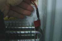
22 DISASSEMBLY AND REASSEMBLY 3-3. Multi Duct-Fridge Part Name Description Figure After disengage the Evaporator Cover, pull the Multi duct-fridge in the direction of the front. Multi Duct (Fridge) Disengage the housing connector. 22
 Part Name Description")
 Remove the water filter by pulling it.")

, otherwise water may drip from the dispenser.")
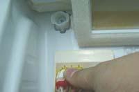
23 DISASSEMBLY AND REASSEMBLY 3-4. Water Filter (Assembly & Disassembly) Part Name Description Figure Turn the water filter count-clockwise. (Refer to the picture) Remove the water filter by pulling it. (Refer to the picture) Water Filter Push the water filter directly. Turn the water filter clockwise until it locked. CAUTION Be sure to flush the dispenser thoroughly (approx. 6 to 7 minutes), otherwise water may drip from the dispenser. This means that there is still air in the line. 23


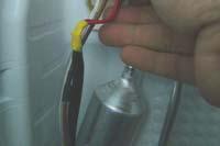
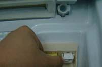
24 DISASSEMBLY AND REASSEMBLY 3-5. Case Water Filter Part Name Description Figure Before disassembling the Case Water Filter take out water filter and drawers and shelves located on the Case Water Filter. Remove screws. While pushing the Tube Fitting, remove the 2 Water Tube. Case Water Filter Turn the refrgerator back and remove the Water Tube. Pull the Water hose out. Disconnect the Housing. Pick the Case Water Filter out. 24


25 DISASSEMBLY AND REASSEMBLY 3-6. Cover-Display & Water-Dispenser Part Name Description Figure Remove a screw under the display cover. Cover-Display Remove the display cover by pulilng it up. Disengage the housing connect of display cover. 25


26 DISASSEMBLY AND REASSEMBLY 3-7. Water-Dispenser Part Name Description Figure Disengage the Housing Connectors by pushing a flatblade screwdriver. Remove 2 screws of the Case Ice Route Assy. Pull the Case Ice Route Assy. Water-Dispenser Assembly shall be in order from the disassembly. Case-Ice and Route shall be assembled inside of hose. Otherwise, assemble cannot be accomplished. When assembling Cover-Display, first insert it from lower and then assemble to upper. (Check the wire inside.) and knock the display into the Case dispenser. After leveling, check the dispenser (water supply, operation of auger motor) for pushing lever dispenser. 26


27 DISASSEMBLY AND REASSEMBLY 3-8. Interior-Freezer Part Name Description Figure Shelf Pull the Shelf out to the front. Remove all Drawers before disassembling the cover. Drawer Cover Pull the cover out to the front. 27


28 DISASSEMBLY AND REASSEMBLY 3-9. Evaporator Cover-Freezer Part Name Description Figure Remove the Cap Screw. Evap. Cover (Freezer) Remove the 4 screws by turning counterclockwise. Pull the Evap. Cover in the direction of the front. 28
 Part Name")


. Multi Duct (Freezer) 4.")


29 DISASSEMBLY AND REASSEMBLY Multi Duct (Freezer) Part Name Description Figure 1. Disassemble the INSULATION DUCT after remove the tape. 2. Disassemble the Electricallydriven DAMPER after disassemble the INSULATION DUCT REF UP. 3. Remove the two COVER SCREW which is on the center of freezer by driver(-). Multi Duct (Freezer) 4. Remove the four SCREW of COVER EVA FRE. 5. Hold the bottom of COVER EVA FRE and pull it to disassemble. 6. Hold the bottom of MULTI COVER and pull it. And than hold the upper and disassemble it completely. 29


30 DISASSEMBLY AND REASSEMBLY Deodorizer Part Name Description Figure 1. Remove the Cover Deodorizer using flat head driver. Cover Deodorizer 2. Replace Catalyst. 3. Reassemble in the reverse order. 30


31 DISASSEMBLY AND REASSEMBLY Assembly Hinge-Up Disassembling (Freezing Compartment) Part Name Work sequence Remarks 1. Disconnect the power cord, and Remove 3 cover screws using a Phillips screwdriver. Then open the refrigerator door and pull the hooks on the sides to loosen the cover. Lift up the cover and towards you to detach it. 2. Disassemble two connectors of the housing. Door 3. Push the fixer hinge up, and pull it forward to remove it. 4. Dissemble the top hinge from the front the door. 31
")


32 DISASSEMBLY AND REASSEMBLY Assembly Hinge-Up Disassembling (Show Case of Cold Compartment) Part Name Work sequence Remarks 1. Disconnect the power cord, and Remove 3 cover screws using a Phillips screwdriver. Then open the refrigerator door and pull the hooks on the sides to loosen the cover. Lift up the cover and towards you to detach it. 2. Disassemble two connectors of the housing. Door 3. Disasemble the three fastening screws on the top hinge of the show case. 4. Dissemble the top hinge from the front the door. 32
 Part Name Work")


33 DISASSEMBLY AND REASSEMBLY Assembly Hinge-Up Disassembling (Cold Compartment) Part Name Work sequence Remarks 1. Disconnect the power cord, and Remove 3 cover screws using a Phillips screwdriver. Then open the refrigerator door and pull the hooks on the sides to loosen the cover. Lift up the cover and towards you to detach it. 2. Disassemble two connectors of the housing. 3. Push the fixer hinge up, and pull it forward to remove it. Door 4. Dissemble the top hinge from the front the door. 5. Diassemble the entire door. 33
 Part")


34 DISASSEMBLY AND REASSEMBLY Assembly Locker Disassembling (Cold Compartment) Part Name Work sequence Remarks 1. Disassemble the entire door as described in Section 3-5, and lay the door on the floor, and disassemble the two fastening screws on the cover lock of the internal door. Door 2. Disassemble the two fastening screws on the locker of the external door. 3. Assemble the doors in reverse order of disassembling. 4. Once assembling is complete push the lever with a hand and check if the cam lock on the internal door is lifted toward the bottom of the door. 34

 or the line (Type B) to prevent water leakage from the")
35 DISASSEMBLY AND REASSEMBLY Part Name Description Figure With the Door closed, remove the door from Remove the Upper Hinge with handling Wires. Door Remove the door from the lower hinge by lifting up the door straight. CAUTION Be careful not to pinch the water tubing and the wire harness on the door. Lift up the door straight in upper direction until the water hose is eliminated from lower hinge. Do not pull the door forward to remove it. It cause injury of water hose and tubing. Part Name Description Figure Type A Reassembly doors The Water Line must be fully inserted to the center of transparent coupler (Type A) or the line (Type B) to prevent water leakage from the dispenser. Insert the clip in the install pack and check that it holds the line firmly. Center of Transparent coupler Type B Dispenser clip A (1/4 ) (6.35mm) The Guide Lines clip A (1/4 ) (6.35mm) 35
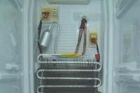
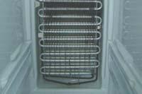
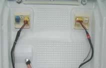
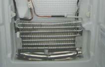


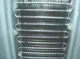
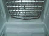
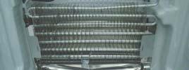
36 DISASSEMBLY AND REASSEMBLY Evaporator Part Name Description Freezer Figure Fridge Remove the Evaporator cover. Disengage the housing connector. (left) Evaporator Disengage the housing connector. (right) Remove the evaporator by pulling the lower part of the evaporator while lifting it up. 36
 Work sequence Remarks 1.")

.")

37 DISASSEMBLY AND REASSEMBLY Main PCB and Inverter PCB Disassembling (whole) Work sequence Remarks 1. Pull the refrigerator forward to make space for servicing. 2. Disassemble the four screws. 3. Disassemble the thirteen connectors of the housing(number of the housing connectors may vary dependent upon models and functions). While pressing the upper hook on the location shown on the figure, pull the main main PBA and remove it. 4. Disassemble the five connectors of the housing. While pressing the hooks on the left and the right side on the locations shown on the figure, pull the inverter PBA and the SMPS PBA to remove them. 37


38 DISASSEMBLY AND REASSEMBLY Disassemble the WIFI module. Part Name Description Figure 1. Disassemble the top table after loosen 3 screw which is supported the top table. 2. Disassemble two connectors of the housing. WIFI module 1. Press the hook of case PBA to disassemble. 1. Disassemble the wire which is connected by power conversion boards. 2. Press the hook of power conversion module to disassemble. 38


39 DISASSEMBLY AND REASSEMBLY COMP Cooling Fan Replacing Work sequence Remarks 1. Remove five screws from the Comp Cover. 2. Remove the drain hose. Disassemble one screw. 3. Disassemble the connector. 4. Pull the connector forward, and incline it toward the drain hose. 5. Rotate the connector around the pipe. 6. Once disassemble the fan is complete, assemble the fan in reverse order of disassembling. 39


40 DISASSEMBLY AND REASSEMBLY COMP Cooling Fan Replacing For E-cost model Work sequence Remarks 1. Remove five screws from the Comp Cover. 2. Remove the drain hose. Disassemble one screw. 3. Disassemble the connector. 4. Pull the connector forward, and incline it toward the drain hose. 5. Rotate the connector around the pipe. 6. Once disassemble the fan is complete, assemble the fan in reverse order of disassembling. 40


41 DISASSEMBLY AND REASSEMBLY COMP Cooling Fan Motor Replacing Work sequence Remarks 1. Remove the spring with a flat screwdriver. 2. Hold the motor, and pull the fan out to remove the fan. 3. Remove two screws from the motor. 4. Use a flat screwdriver to remove the bracket motor. 5. After pulling the bracket motor, remove the motor. 41
 Work sequence Remarks 1.")


42 DISASSEMBLY AND REASSEMBLY Relay Protector O/L disassembling (Whole) Work sequence Remarks 1. Remove five screws from the Comp Cover. 2. Remove the cover relay with a flat screwdriver. CAUTION Caution: Pipe bending or exercise of excessive force may pinching on the hands when removing the cover. 3. User a flat driver to disassemble the relay protector from the compressor. 4. Pull the connector to disassemble the relay as shown on the figure. 42
 Work sequence Remarks 1.")


43 DISASSEMBLY AND REASSEMBLY Step Valve Disassembling (whole) Work sequence Remarks 1. Remove five screws from the Comp Cover. 2. Disassemble the housing connector from the step valve. 3. Disassemble one screw, and pull the step valve up to remove the valve as shown on the figure. 4. Remove the refrigerant, and disassemble the step valve from the connection pipe. CAUTION Exerting excessive force when forming the pipe causes bending of the pipe. 43


44 DISASSEMBLY AND REASSEMBLY Ice Maker Compartment Part Name Description Figure Ice Bucket Assy Disassemble the Ice-Bucket Assy by holding the handles and pulling up the bottom part slightly. Cover I/M Lift up the Icemaker Cover and gently pull out. Unscrew the 4 screws and disassemble the Auger Motor Assy as shown. Assy Ice Maker-Indoor Disconnect the housing connectors by gently pulling. Unscrew the 3 screws. Ice Maker Assy Disassemble the Ice Maker Assy. 44


45 DISASSEMBLY AND REASSEMBLY Auger-Motor Part Name Description Figure Auger- Motor 1. Pull the shelf out to the front side. 2. Unscrew 4 screws by turning counterclockwise. 3. Disconnect the housing connector by pulling as shown. 45


46 DISASSEMBLY AND REASSEMBLY Disassembling the internal handle Part Name Work sequence Remarks 1. Rotate one set screw counterclockwise with a hexagonal wrench to remove it from the bottom of the handle. Handle 2. Pull the bottom of the handle to remove it. 3. Slide the entire handle downward to disassemble it Disassembling the external handle Part Name Work sequence Remarks 1. Use a Philips screwdriver to remove six screw caps. Handle 2. Disassemble six set screws of the handle to remove the handle. 46
47 4. TROUBLESHOOTING 4-1. Function for failure diagnosis Diagnostic method according to the trouble symptom(flow Chart)
48 TROUBLESHOOTING 4-1. Function for failure diagnosis Test mode (manual operation / manual defrost function) If Freezer Key + Alarm Key on the front of panel are pressed simultaneously for 8 seconds, it will be changed to the test mode and all displays on the front of panel will be off. If any key on the front of panel is pressed within 15 seconds after the test mode, it will be operated as below sequence : Manual operation(ff) -> manual defrost of freezer compartments(fd) -> cancel(display all off) If any key on the front of panel is not pressed within 15 seconds after the test mode, the test mode will be canceled and it will be returned to previous mode. 1) Manual operation function Freezer Key + Alarm Key are pressed simultaneously for 8 seconds, (displays are all off) It will be changed to the test mode (manual operation) by pressing any key. 1-1) If any key is pressed once in test mode, blinks "FF" on the display and it indicates the refrigerator has entered the manual operation. At this moment, buzzer beeps as an alarm. 1-2) If manual operation is selected, compressor will run at once without 7 minutes delay in any mode. If the refrigerator is on the defrost cycle at the moment, defrost will be finished and manual operation will begin.(be careful if manual operation get started at the moment of compressor off, over load could be occurred) Compulsion working : 3600RPM 1-3) If manual operation works, compressor & f-fan operate continuously for 24 hours and fresh food compartment will be controlled by the setting temperature. 1-4) When the manual operation runs, setting temperature will be selected automatically as below: freezer compartment -8 F(-23 C), fresh food compartment 34 F(1 C). 1-5) During manual operation, Power Freeze & Power Cool function will not be work. If a function is selected, the power function icon of the selected function will be off automatically after 10 seconds. 1-6) Manual operation can be canceled by removing power from the unit, then resupplying power. 1-7) Alarm(0.25 sec ON/ 0.75 sec OFF) will beep continuously until manual operation is completed and there is no function to make the sound stop. 48
49 TROUBLESHOOTING 2) Forced Defrost 2-1) When you press any key one more time at the manual operation status, Fd lights up on the Display Panel. At this time, the Forced Operation stops immediately and F-Defrost will be performed at the same time. 2-2) At this time, it will send out Beep sound for 2 seconds and then it will perform Forced F Defrost while sending out 0.5 sec On and 0.5 sec Off sound. 3) Test cancel mode 3-1) During the defrosting of freezer compartment if the display panel change to the test mode and test button is pressed one more time, defrosting of freezer compartment will be canceled and the unit will return to the normal operation. Or, all test functions will be canceled by turning main power ON and OFF Display function of Communication error 1) Display function when Panel MAIN MICOM communication has error 1-1) If there is no answer for 10 seconds after the panel micom received the requirement of communication, "PC - Er" or "PC - Ch" display on the panel PCB will be ON/OFF alternately until the communication error is canceled. (0.5 sec ALL ON, 0.5 sec ALL OFF alternately) 1-2) PC - Er" or "PC - Ch" display on the Panel Display will be ON/OFF alternately until the communication error is canceled. (0.5 sec ALL ON, 0.5 sec ALL OFF alternately) 2) Display function when Panel MAIN MICOM OPTION has error 2-1) "op - Er" or "op - Ch" code is repeatedly ON/OFF until Option error settles down. 49
50 TROUBLESHOOTING Self-diagnostic function 1) Self-diagnostic function in the Initial power ON 1-1) Micom operates self-diagnostic function to check the temperature sensor condition within 1 second when the refrigerator turned On initially. 1-2) If bad sensor is detected by the self-diagnostic function, the applicable display LED will blink for 0.5 sec. At this moment, there is no beep sound.(refer to self-diagnostic CHECK LIST) 1-3) Self-diagnostic button is recognized only when the error is displayed by the bad sensor. Display does not operate normally but temperature control will be controlled by the emergency operation. 1-4) When the error is detected by self-diagnosis, the error can be canceled automatically if all troubled sensors are corrected or Self-diagnostic function key (Freezer Key + Fridge Key ) are pressed simultaneously for 8 seconds. (Return to normal display mode) If Freezer Key + Fridge Key are pressed simultaneously for 8 seconds, the error mode by selfdiagnosis will be canceled. 2) Self-diagnostic function during normal operation If Freezer Key + Fridge Key are pressed simultaneously for 8 seconds, the self-diagnosis function will be selected. 2-1) If Freezer Key + Fridge Key are pressed simultaneously for 6 seconds during normal operation, the temperature setting display will operate for 2 seconds (ON/OFF 0.5sec each). If Freezer Key + Fridge Key are pressed simultaneously for 8 seconds (including above 2 seconds), self-diagnostic function will be selected. 2-2) At this moment, self-diagnostic function will be returned with buzzer sound 'ding-dong'. If there is an error, display of error will be operated for 60 seconds and then return to normal condition whether problem is corrected or not. (Refer to self-diagnosis CHECK LIST) 2-3) Input by button is not accepted during self-diagnostic function. 50
51 TROUBLESHOOTING Self-diagnostics check list F LED R Item Trouble contents Diagnostic method F-Sensor Error When measuring the voltage between the Main PCB CN30 3PIN - 7PIN, it should read between 4.5V~1.0V. R-Sensor Error F-DEF-Sensor Error Display error : separation of sensor housing part, contact error, disconnection, short circuit. Display error of detecting temperature of sensor : more than 149 F(+65 C) or less than -58 F(-50 C) When measuring the voltage between the Main PCB CN30 5PIN - 7PIN, it should read between 4.6V~1.0V. The voltage of MAIN PCB CN30 4PIN - 7PIN shall be between 4.5V~1.0V or Ambient-Sensor Error Ice Maker Sensor Error Humidity-Sensor Error F-FAN Error C-FAN Error F-DEF Error Ice Maker Function Error Damper-Heater Error Panel Main Communication Error Display error : separation of sensor housing part, contact error, disconnection, short circuit Display error of detecting temperature of sensor: more than 149 F (+65 C) or less than -58 F(-50 C) Separation of sensor housing part, contact error, disconnection, short circuit Display error during operation of applicable fan motor : Feed back signal line contact error, motor wire separation, motor error Display error during operation of applicable fan motor : Feed back signal line contact error, motor wire separation, motor error Separation of freezer compartment defrost heater housing part, contact error, disconnection, short circuit or temperature fuse error. Display error : the defrosting does not finish though freezer compartment defrost is heating continuously for more than 100 minutes. When the Freezer Ice Maker error occurs more than 3 times, the error will be displayed. Display error when open error is detected by damper heater : separation of Damper Heater housing part, contact error, disconnection, short circuit. Display pc - Er in the panel with alarm : MICOM MAIN PANEL communication error. The voltage of MAIN PCB CN30 11PIN - 7PIN shall be between 4.5V~1.0V The Voltage of MAIN PCB CN90 3PIN - 9PIN Shall be between 4.5v ~ 1.0v When measuring the voltage between the Main PCB CN30 12PIN - 7PIN, it should read between 4.5V~1.0V. The voltage of MAIN PCB CN74 4PIN - 1PIN shall be between 7V~12V The voltage of MAIN PCB CN74 2PIN - 1PIN shall be between 7V~12V After separating Main PCB CN70& SMPS CN01 wire from PCB, Resistance value between CN70 9PIN SMPS CN01 3PIN 7%.(Resistance value is varied by input power) 0 ohm : heater short, ohm : wire/bimetal open (Must power off) After replacing the Ice Maker, check if it operates normal. After separating MAIN PCB CN75 wire from PCB, resistance value between CN74 1PIN - 2PIN wire shall be 135 ohm± 7%. 0 ohm : heater short, Ohm : wire / bimetal Open. Actually, If there is not a problem, it is desirable to replace Main and Panel PCB With the oscilloscope after a cable problem confirming. Main - Inverter Communication Error Display 44Er in the panel : Inverter MICOM Main MICOM communication error. Actually, If there is not a problem, it is desirable to replace Main and Inverter PCB With the oscilloscope after a cable problem confirming. 51
52 TROUBLESHOOTING Self-diagnostics check list F LED R Item Trouble contents Diagnostic method I/O Expander Communication Error Display 46Er in the panel : I/O Expander Main MICOM communication error. It is desirable to replace Main PCB. The F compartment abnormal hightemperature indicator blinks When the freezer temperature is abnormally high or the freezer door is open for a certain period of time and the freezer temperature increases, the freezer display blinks. The temperature has been abnormally increased. Check if the door has been open for a long time or if hot food has been stored in the compartment. If the reason for the error is removed, the error code disappears after a predetermined period of time. The R compartment abnormal hightemperature indicator blinks When the freezer temperature is abnormally high or the fridge door is open for a certain period of time and the fridge temperature increases, the fridge display blinks. Check if door has been open for a long time or if hot food has been stored in the compartment. If the reason for the error is removed, the error code disappears after a pre-determined period of time. or Comp starting Failure Error IPM Fanlt Error When the Compressor fails starting When there is a IPM Fault error Check if there is a short between compressor terminals. Check IPM Voltage [Under 13.5V] Check if there is a short between IPM Pins [#1~33] Check the Compressor and the Cycle Comp Abnormal current Detection Error When there is abnormal current detected at the Compressor Check the Compressor connections Check the voltage of Resistance of R308 [0.09Ohm] Check the Compressor and the Cycle Motor Locked Over RPM Error When there is a Compressor restriction error Check the voltage of Resistance of R308 [Short/Open] Check the voltage of both of C103 terminals [Unstable Voltage] Check the Compressor and the Cycle Comp under voltage Error When there is a low voltage error Check the voltage of Resistance of R513 [Short/ Open] Comp over voltage Error When there is a over voltage error Check the voltage of Resistance of R501, R505, R509 [Short/Open] F R 52
53 TROUBLESHOOTING Display function of Load condition If Freezer Key + Fridge Key are pressed simultaneously for 6 seconds, ALL ON/OFF will blink with 0.5interval for 4 seconds. If take the finger off from above keys and press Alarm, load condition mode will be started. 1) If Freezer Key + Fridge Key are pressed simultaneously for 6 seconds during normal operation, the temperature setting display of fresh food and freezer compartments will blink ALL ON/OFF with 0.5 for 4 seconds. 2) At this moment, If Alarm Key after Freezer Key + Fridge Key is pressed, load condition display mode will be returned with alarm. At LED all on state, only load condition display will blink ON/OFF with 0.5 seconds interval. 3) Load condition display mode shows the load that micom signal is outputting. However, It means that micom signal is outputting, it does not mean whether load is operating or not. That is to say that though load operation is displayed, load could not be operated by actual load error or PCB relay error etc. (This function would be applied at A/S.) 4) Load condition display function will maintain for 30 seconds and then normal condition will be returned automatically. 5) Load condition display is as below. Only the load control LED will blink with 0.5interval in "Display LED" F-10 F-1 R-10 R-1 53
54 TROUBLESHOOTING Load mode Check list Display LED Display contents Operation contents Overload condition When ambient temperature is more than 93 F(34 C), LED blinks Low temperature condition When ambient temperature is less than 72 F(22 C), LED blinks Normal Condition When ambient temperature is between 73 F(23 C) and 91 F(33 C) Exhibition Mode LED blinks at the display mode. COMP. When COMP operates, applicable LED blinks. F-FAN High When FZ compartment FAN operates with high speed, applicable LED blinks. F-FAN Low When FZ compartment FAN operates with low speed, applicable LED blinks. F-DEF Heater When FZ compartment defrost heater operates, LED blinks C-FAN High When compressor FAN operates with high speed, applicable LED blinks. C-FAN Low When compressor FAN operates with low speed, applicable LED blinks. Homebar(Door) Heater When Homebar(Door) heater operates, applicable LED blinks. Ice maker full When the Ice Maker's Bucket is full, applicable LED blinks Dispenser Heater When Dispenser heater operates, applicable LED blinks. Damper Open When damper open, applicable LED blinks. F-FAN Highest When FZ compartment FAN operates with highest speed, applicable LED blinks. 54
55 TROUBLESHOOTING Cooling OFF mode setting function North American(US, Canada) Models Only If Freezer Key + Lighting Key + Fridge Key are pressed for 5 seconds, Cooling Off mode will be started. 1) If Freezer Key + Lighting Key + Fridge Key are pressed simultaneously for 5 seconds during normal operation, Cooling Off mode will be started with buzzer sound(ding-dong). 2) If above Freezer Key + Lighting Key + Fridge Key are pressed one more time, Cooling Off mode will be canceled. 3) If Cooling Off mode is selected, blinks "O-FF" on the temperature setting display of the panel and it indicates the refrigerator has entered the Cooling Off mode. 4) During Cooling Off mode, if fresh food and freezer compartments sensors are higher than 149 F (65 C) Cooling Off mode will be canceled automatically and freezing operation will be returned. (There is no buzzer sound when the Cooling Off mode is canceled by the temperature) 5) Operation contents of Cooling Off mode - Display, Fan motor and etc operate normally, not to operate compressor and Door Open Alarm. - Defrost is not operated. (including french heater) - Display function of the initial real temperature is finished. - Under the condition of Cooling Off mode, Cooling Off mode will be operated when Power On after Power OFF AP Mode Function and E-Smart Icon 1) AP Mode Function makes refrigerator s status to can be connected to the Network. 2) If you Press for 3 seconds Fridge Key and Energy Saver Key together, AP Mode function is turned on or off. 3) When AP Mode is turned on, the user can connect the refrigerator to the network. 4) E-Smart Icon shows connection status of the refrigerator and network. 5) When turned off the E-Smart Icon, it indicates that any network device is not connected. When turned on the E-Smart Icon, it indicates that the refrigerator is connected to the network or AP device. 55
56 TROUBLESHOOTING Option setting function If Lighting Key + Fridge Key are pressed simultaneously for 12 seconds during normal operation, fresh food and freezer compartments temperature display will be changed to option setting mode. KEY operation method for changing to option mode If Lighting Key + Fridge Key are pressed simultaneously for 12 seconds, option setting mode will be started. KEY control method after converting to option mode Code Down Code Reference Value Reference Value down key Code Up Reference Value Up key Key control in option mode Freezer Key Lighting Key Fridge Key Alarm Key Code Down key Code Up key Reference Value down key Reference Value Up key If the display changes to option setting mode, all displays will be off except freezer and fridge compartments temperature display as below. (Fresh food and freezer compartments case will be explained only because all options are operated with the same method according to the option table.) 56
57 TROUBLESHOOTING Code Reference Value 1) For example, if you want to change freezer compartment standard temperature to -4 (-2 C) by operating option, do as below. This function is for changing the standard temperature. In -2 (-19 C) of current temperature of freezer compartment, if you make the temperature lower to -4 (-2 C) by the option, the standard temperature would be controlled -6 (-21 C) Therefore, if you change the setting of temperature option to -2 (-19 C) on the panel, the appliance will be operated with C). It means that standard temperature is controlled -4 (-2 C) less than setting temperature in the display. TE Basically, all the data in option has cleared from the factory. Therefore, almost all setting value are "0". But, some setting values could be changed for the purpose of improving performance. You need to check the product manual and/or specification. 2) After changing to the option mode, fresh food compartment "0", freezer compartment "0" will be displayed. ( Basically fresh food compartment "0", freezer "0" would be set at shipping process, but setting value could be changed for the purpose of improving product at mass producing process.) - If fresh food compartment "0" shows only, temperature reference value of freezer compartment will be set and current freezer compartment temperature code will be displayed on the freezer temperature display. 3) If freezer compartment "4" is set as below freezer compartment code after fresh food compartment "0 is set, standard temperature of freezer compartment will be lower than -4 (-2.0 C). (Refer to the picture "changing the freezer compartment temperature") Code Reference Value : If you wait for 20 seconds after completing the setting, MICOM will save the setting value to the EEPROM and normal display will be returned and the option setting mode will be canceled. 4) Option changing method as above is the same as all RH22*, RH29* model. 5) By the same method as above, it is possible to control the fresh food compartment temperature, water supply, ice-maker harvest temperature/time, etc. 6) Option function is set in the EEPROM at shipping process in the factory. You would better not to change the option of your own. Completing the setting is that option function return to normal display after 20 seconds. Do not turn off the appliance before returning to the normal display mode. TE Option setting function exists in the other items. We will skip the explanation of the other functions by the option because it is associated with refrigerator control function and is not needed at SERVICE. (Please do not set the other options except above SERVICE Manual.) 57
58 TROUBLESHOOTING Option TABLE 1) Temperature changing table of freezer compartment Set item Freezer Temp Shift Reference Fridge Room 7-SEG Value 0 Setting value FZ compartment Code Temp. compensation 0 0 F(0.0 C) 1-1 F(-0.5 C) 2-2 F(-1.0 C) 3-3 F(-1.5 C) 4-4 F(-2.0 C) 5-5 F(-2.5 C) 6-6 F(-3.0 C) 7-7 F(-3.5 C) 8 +1 F(+0.5 C) 9 +2 F(+1.0 C) F(+1.5 C) F(+2.0 C) F(+2.5 C) F(+3.0 C) F(+3.5 C) F(+4.0 C) Code Reference Value 2) Temperature changing table of fresh food compartment Set item Fridge Temp Shift Reference Fridge Room 7-SEG Value 1 Setting value FZ compartment Code Temp. compensation 0 0 F(0.0 C) 1-1 F(-0.5 C) 2-2 F(-1.0 C) 3-3 F(-1.5 C) 4-4 F(-2.0 C) 5-5 F(-2.5 C) 6-6 F(-3.0 C) 7-7 F(-3.5 C) 8 +1 F(+0.5 C) 9 +2 F(+1.0 C) F(+1.5 C) F(+2.0 C) F(+2.5 C) F(+3.0 C) F(+3.5 C) F(+4.0 C) ex) If you want to change the freezer compartment standard temperature to 4 F(2 C) Code Reference Value 58
59 TROUBLESHOOTING 3) Ice Tray water supply of freezer compartment Ice Maker Set item FZ-Room ICE TRAY Reference Fridge Room 7-SEG Value 3 Setting value FZ compartment Code Water Settings. 0 94cc 1 104cc 4) Eject waiting time changing table of freezer compartment Ice Maker Set item FZ-Room Ice Maker Eject waiting time Shift Reference Fridge Room 7-SEG Value 3 Setting value FZ compartment Setting time Code 0 60min 1 47min 2 45min 3 53min 4 55min 5 57min 6 65min 7 70min 8 50min 5) Eject temperature changing table of freezer compartment Ice Maker Set item FZ-Room Ice Maker Eject temperature Shift Reference Fridge Room 7-SEG Value 4 Setting value FZ compartment Code Temp. compensation C C C C C C C C 59
60 TROUBLESHOOTING 6-1) Minimum Comp RPM shifting -This option is rising minimum Comp RPM. As this option is applied, Comp operation. Set item Minimum Comp RPM setting Reference Fridge Room 7-SEG Value 12 Setting value FZ compartment Comp RPM Code 0 No RPM Change 1 Minimum 2450RPM 2 Minimum 2450RPM 3 Minimum 2450RPM 6-2) Minimum Comp RPM shifting For E-Cost -This option is rising minimum Comp RPM. As this option is applied, Comp operation. Set item Minimum Comp RPM setting Reference Fridge Room 7-SEG Value 12 Setting value FZ compartment Comp RPM Code 0 No RPM Change 1 Minimum 2050RPM 2 Minimum 2050RPM 3 Minimum 2050RPM 7) Temp Display Option -This option is for temp display all on mode. If user wants temp display always on, this option is solution. Set item Temp Display Option Reference Fridge Room 7-SEG Value 16 Setting value FZ compartment Temp Display Option Code Normal Display (Temp display 0 temporally on at use) 1 Always Temp Display On 2 Always Temp Display On 60
61 TROUBLESHOOTING 8) Operation rate changing table of dispenser heater Set item Dispenser Heater Rate Reference Fridge Room 7-SEG Value 19 Setting value FZ compartment Rate change Code % + 20% operation 1 ( up to 100% ) Code Reference Value ex) If you want to change the dispenser heater operation rate to +20% 61
62 62 TROUBLESHOOTING 4-2. Diagnostic method according to the trouble symptom(flow Chart) DATA1.Temperature table Resistance value and MICOM port voltage of sensor according to the temperature SENSOR CHIP : based on PX41C, PX41C, 502AT/ 103**(ICE MAKER SENSOR(MOLD)/FULL UP, 20Kohm ( Actual measurement = value of the table below X 2 ) Voltage Resistance Voltage Resistance Voltage Resistance
63 63 TROUBLESHOOTING DATA2. Humidity Sensor table - Voltage output 5Vdc --- HTG3515CH/HTG3535CH RH(Temperature compensate ) = RH (Relative Humidity ) + ( Temp( C) 23 C) x Voltage Voltage Voltage Resistance Resistance Resistance
")
64 TROUBLESHOOTING Power Not Supplied (SMPS PCB) CAUTION 64
 CN30 Replace the sensor F-DEF Heater is normal F-DEF-HEATER : Read resistance between MAIN PBA CN70 #9 and SMPS PBA CN01 #3")

65 TROUBLESHOOTING Unable to Defrost CN70 Start F-DEF Sensor is normal (with Self Diagnosis) CN30 Replace the sensor F-DEF Heater is normal F-DEF-HEATER : Read resistance between MAIN PBA CN70 #9 and SMPS PBA CN01 #3 Check Thermistor, Heater and their connectors Defrost Sensor Voltage is lower than 3.1V Defrost Sensor Temp is lower than -5 C Forced Operation for a certain time Press the Power Freeze and the Fridge buttons at the same time for 8 sec and then go into the 2nd Test Mode. Forced F Defrost F-DEF-SENSOR : Read resistance between CN30 #3 and #7 Power is supplied to Defrost Heater Check all the sensors It goes back to Cooling Operation after heating Note When F-DEF Sensor is higher than +10 and +17, it will stop heating and go back to Cooling Operation. Normal MAIN PBA connectors are normal Check Thermistor, Heater and their contacts. Repair or Replace defective relays, or PBA Ass'y Repair the connectors Sensor Check Point (CN30) 2PIN-1PIN : EXT-SENSOR 2PIN-3PIN : F-SENSOR 2PIN-4PIN : F-DEF-SENSOR 2PIN-5PIN : R-SENSOR 2PIN-6PIN : R-DEF-SENSOR 2PIN-9PIN : CV-SENSOR 2PIN-10PIN : CV-DEF-SENSOR 2PIN-11PIN : HUM1-SENSOR 2PIN-12PIN : HUM2-SENSOR 2PIN-13PIN : ICEROOM-SENSOR 2PIN-14PIN : PANTRY-SENSOR 65

66 TROUBLESHOOTING Self-Diagnosis Error (Defective Sensor) When there is sensor error, display panel show that. When it occurs during the initial power on time, display panel keeps blinking relevant 7-SEG and the refrigerator go into the emergency operation mode. Under the emergency operation mode, the refrigerator can not do its normal operation. So check out with the Self Diagnosis in this manual. 1) When the Ambient Sensor is defective, Start MAIN PBA connector (CN30) is inserted properly. CN30 Ambient-Sensor : Read the resistance between CN30 #1 and #2 Compare the room temp. with sensed temp. using Temp-Resistance Table. Ambient Tem p Sensor is ok. PBA & Thermistor are ok. Check the contact of the connector again. Repair the defective contact of the connector or insert the connector properly Replace Thermistor 2) When the Fridge Temp Sensor is defective (also applied to other sensors) Start CN30 Refer to Circuit Diagram and Temp Sensor Troubleshooting in this manual. Refer to Circuit Diagram and Temp Sensor Troubleshooting in this manual. Fridge Sensor is good. MAIN PBA Connector (CN30) is properly inserted The order of Connector(CN30) is the same as the one in the circuit diagram The voltage between CN30 #2 and #5 is within the normal range PBA & Thermistor are good. Check the contact of the connector again. Replace Thermistor Repair the defective contact of the connector or insert the connector properly Check the circuit diagram and correct any wrong inserted connectors Check MAIN PBA Cold Solder or Short 66
67 TROUBLESHOOTING When Alarm Sound continues (Buzzer Sound) 1) When "DingDong" sound continues Start F-Door sensing : CN50 #6-#9 R-Door sensing : CN50 #7-#9 Nomal State -Door Open : 5 Vdc -Door Close : 0 Vdc Door is closed completely? Closed well Is water penetrated into the door switch? Door sensing voltage changes as the door gets open or closed. The connector(cn50) is Inserted properly Door is ajar Romove causes after comprehending the condition of interference by door gasket or food etc Replace Door switch Repair wire connection and door switch Separate the Door S/W and check its resistance change according to s/w on(0 ) and off( ) Door S/W is good. Repair the defective contact of the connector or insert the connector properly Replace REED S/W MAIN PBA & DOOR S/W are good 2) When "Beeping" sound continues Start Forced Operation or Forced Defrost is selected After plugging in again, it sounds continuously Replace Panel PBA Cancel Forced Operation or Forced Defrost, or Re-plug the unit Panel PBA is normal 67
68 TROUBLESHOOTING 3) If a buzzer does not sound This model has a buzzer on the Panel PBA. If the buzzer does not sounds when button is pressed, Forced Operation, door open and disconnection with Main PBA, check out defective soldering on PBA or buzzer damage. (It is recommended replacing Panel PBA if components are damaged) It could be unable to hear in case there is heavy noise or built-in environment. Start "DingDond" Sounds when a button on the display panel is pressed Door alarm sounds after any of doors are open over 2 min. The Buzzer surface is broken or bended. Buzzer lead comes off from the vibration plate. Check & Replace a buzzer on Panel PBA Normal Buzzer Breakage Replace Buzzer or Panel PBA Check the button press force and structural design (Door Sensing) Replace Panel PBA 68
69 TROUBLESHOOTING When PANEL PBA operates abnormally 1) When PANEL PBA does not light up or partially does Start Refer to Circuit Diagram in this manual and check the circuit diagram attached on the back of the unit. The connector at the Freezer upper hinge cover is inserted properly. MAIN PBA Connector (CN50)is inserted properly Re-insert Connector, Correct the defective contact DOOR PANEL PBA Connector is inserted properly It lights up after PANEL-PBA replacement Re-insert MAIN PBA Connector Re-insert Connector, Correct the defective contact Check F/R-Door Wiring - Short or Open Wire Check F/R-CABI Wiring - Short or Open Wire Check Short/Open on MAIN PBA or replace it Defective PANEL PBA 2) When Panel PBA buttons are not working Child Lock is on There are no buttons being pressed continuously. The trouble continues after Panel PBA cover is separated After replacing Panel PBA, it works properly Check F/R-Door Wiring - Short or Open Wire Check F/R-CABI Wiring - Short or Open Wire Check Short/Open on MAIN PBA or replace it Being Pressed Cancel Child Lock and check it again Re-assemble PBA ASS'Y, Correct any restrictions on the buttons When being separated, it works Re-assemble PBA ASS'Y, Correct any restrictions on the buttons Defective PANEL PBA 69
70 TROUBLESHOOTING When Fan does not operate - This model has BLDC FAN motor. BLDC motor is driven by DC7~12V - F-Fan motor usually runs together with the Compressor. Once the door is open and closed at high ambient temperature, F-Fan motor put off its operation for one minute. Therefore, you are advised not to take it as an error. - When fridge door is open, the F-Fan motor stops. Start COMP is on? For C-FAN For F-Fan Run Forced Operation The voltage between GND in Main PBA and CN74 #2 is 8-12Vdc The voltage between GND in Main PBA and CN74 #4 is 8-12 VDC FAN operates normally. Freezer/Fridge/Home Bar Door S/W is closed. Check after closing the Door. When there is Door alarming, repair the Door S/W connector. For C-FAN Reading with Door closed. -.OPEN 5V, CLOSE 0V Plug in again after 5 minutes from the power off. For F-FAN Upon the initial power on, Comp and F/C-Fan operate for 5 minutes regardless of the conditions. The voltage between GND and CN74 #2 repeats the change from 7-12VDC to lower than 2VDC. The voltage between GND and CN74 #4 repeats the change from 7-12VDC to lower than 2VDC. Replace MAIN PBA Note Pulse signal(fg) generated from the Fan motor rotation is transmitted through CN74 #9(F), #11(C) Micom senses these signal. If Micom senses no signal, Micom make Fan Motor stop for 10 sec and try to operate it again. Micom keeps doing the same procedure 4 times until Micom receive the signal. If it still fails, MICOM stop trying for 10 minutes. This procedure prevents the motor from overload when foreign substances such as ice built up around the motor restrict motor rotation. Possible Causes 1. Defective FAN-MOTOR 2. Contact problem at the terminal 3. FG signal error (Refer to Fan-Motor circuit in this manual) Checking method of C-Fan motor voltage -. Read the voltage between MAIN PBA GND and CN74 #2 -. If it has 8~12 voltage, It's normal. (Same method is applied to other Fan Motor) CN74 70
71 TROUBLESHOOTING When the internal lamp of the freezer/fridge does not light up Caution Model with light bulb applied 1. Turn off the power for repair because there is risk of electric shock when replacing the internal lamp. 2. Please keep in mind you could get burnt by the excessive heating of an incandescent light bulb. Reference Internal lamp RELAY switches ON/OFF as the DOOR is OPEN/CLOSE. When the internal lamp is not on, check the operating noise of the RELAY. RELAY operation noise is generated every time as the DOOR is OPEN/CLOSE. Reference 1. When the DOOR is open, the DOOR S/W becomes OPEN. Micom senses 5V from Door S/W and recognizes that the Door is open. If 5V has sensed for more than 2 minutes, buzzer will sounds DingDong every 1 minute. Therefore, if the DOOR S/W is defective, it can generate the Ding Dong sound every 1 minute. 2. ON/OFF control of the internal lamp is linked with the DOOR S/W. Start Is it a light bulb? Is the filament of the intermal lamp blown? Is the Door and Home bar Reed S/W operating normally? Relay for lamp control on PBA is normal? Check and repair F, R-DOOR, home bar S/W connector and socket for internal lamp (LED LAMP) Replace lamp Check REED S/W or check whether door and home bar switch normally Replace PBA and Relay Replace LED LAMP PBA Reed S/W : Open when door is open Short when door is closed Is the Reed S/W operating normally? Check REED S/W or check whether door and home bar are switching normally Is the output of LED-LAMP 12V when Door is open? Check wire disconnection, check DC 12V output Measure voltage between CN76 #1 and #2 when opening the F-Door Measure voltage between CN76 #3 and #5 when opening the R-Door Model with light bulb applied Fridge internal lamp On : Fridge door is open or Fridge HomBar is open Freezer internal lamp On : Freezer door is open or Freezer HomBar is open 71
 Check the main power conversion board CN02 No.5(VCC), No. 4 (GND) pins. (Normal range is: 11.4V ~12.")
 Is the input voltage of main power conversion board as 12V correctly? Progress the WIFI setting again.")
72 TROUBLESHOOTING When the WiFi does not work properly Start Do you have the wireless router? Buy the wireless router (Wireless router is not included) Check the main power conversion board CN02 No.5(VCC), No. 4 (GND) pins. (Normal range is: 11.4V ~12.6V) Is the power of wireless router turned on? Dose the WIFI setting properly? Wireless router power on Check the main power conversion board CN 03 connector No.3(VCC), No.4(GND)pins. (Normal range is : 4.75V ~ 5.25V) Is the input voltage of main power conversion board as 12V correctly? Progress the WIFI setting again. Be cautions about when enter the password (a capital and small letter, blank etc.) Is the six pins connector connected to main power conversion board correctly? Connect the six pins Is the output voltage of main power conversion board as 5V correctly? Change the main power conversion board Is the cable connected to main board CN03 correctly? Connect the cable. Are the main power board and WIFI module connected correctly? Change the main board. Connect the five pins. Change the WIFI module. 72
73 TROUBLESHOOTING Check the WiFi module system PROBLEM STATE 1 STATE 2 EXPECTATION CAUSE SOLUTION WiFi setting is failed. Progress the WiFi setting again. E-Smart LED OFF Select the wrong wireless router. Select the wireless router which is connected with Smart mobile. Remote control is not working. The refrigerator can not search in the APP which is wants to remote control Password is wrong. Select the wrong wireless router. Enter the password correctly. Select the wireless router which is connected with Smart mobile. E-Smart LED ON Wireless router is failed to connect with Smart mobile or area where is not working the wireless internet. Check the smart mobile is connected to wireless router properly which is connected with refrigerator. 73
74 TROUBLESHOOTING LED blinking frequency depending on protecting functions If Failure Condition is detected during compressor is operating, immediately stop Compressor operating and stand by 5 minutes. During this 5 minutes, RPM command signal is not available. It means, even if available RPM command signal is applied to the compressor, it does not work and keep standing by. Blinking time is 1 second and dwell time is 2 seconds. LED Blinking Frequency Protecting Functions Normal Operation Starting Failure IPM Fault Abnormal Current Detection Motor Locked / Over RPM Under Voltage Remarks N/A 1. Short between COMP U,V and W Phase (CN102) 2. Short among IPM Pins (No. #1 ~ 26) 3. Drop the IPM operating Voltage under DC 13.5V 4. Other cases, check the COMP, cycle, etc. 1. Open the COMP wire (CN102) 2. Bad condition of R1(ex. Bad soldering) 3. Other cases, check the COMP, cycle, etc. 1. Operating the locked rotor COMP within 5 second. 2. Operating the COMP under 1,000 RPM more than 5 second. 3. Occur the huge change of input voltage in a moment. 4. Other cases, check the COMP, cycle, etc. 1. Drop the input voltage under AC 53V 2. Short resistor R525 (DC link Resistor) Over Voltage Communication Error 1. Increase the input voltage over AC 155V 2. Short resistor among R522, R523 and R524 (DC Link Resistor) 1. Check Terminal CN Short or Open resistor R210, R Short or Open harness between Main and Inverter LED blinking frequency depending on protecting functions If the same blinking, After 5 minutes, Follow the Remarks 74
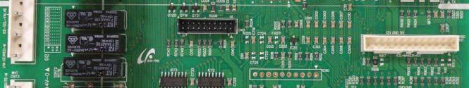
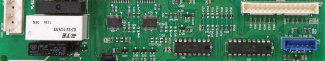
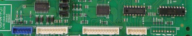
75 5. PCB DIAGRAM 5-1. PBA Layout with part position PBA Layout with part position (Inverter Board) Connector Layout with part position (Main Board) Connector Layout with part position (Inverter Board)
76 This document can not be used without Samsung's authorization PCB DIAGRAM 5-1. PBA Layout with part position A. Diode option setting B. Step valve & LED Room lamp controlling circuit C. Ice maker kit control D. Damper & Damper heater control E. dispenser controlling part F. Panel PBA communication and power supply circuit G. Defrost Heater controlling part H. Inverter Comp driving signal section I. Fan Motor driving circuit : It supplies to various types of motors J. WIFI Communication circuit K. By receiving various sensor signals, it sends them to MICOM after removing noise. 76
77 This document can not be used without Samsung's authorization PCB DIAGRAM 5-2. PBA Layout with part position (Inverter Board) 1. PCB Power Supply : From the AC Input Voltage(115V), it supplies DC 15V and 5V to the Inverter circuit for the Compressor control. 2. COMP Driving / Feedback Circuit It receives the COMP operation signals from the Main PBA and feedbacks the inverter errors to the Main PBA. 3. Micom (MN103SFC2D) 4. BOOTSTRAP Charger : It is an independent power circuit for the driving of the IMP High-Phase IGBT. 5. Current Pickup Circuit : It pickups the currents taken by the Shunt resistance and does the PWM DUTY control. 6. IPM (FNB40560) 77


78 This document can not be used without Samsung's authorization PCB DIAGRAM 5-3. Connector Layout with part position (Main Board) 78
 AC 115V COMP 1 : DC 5V 2 : GND 3 : COMP.")
79 This document can not be used without Samsung's authorization PCB DIAGRAM 5-4. Connector Layout with part position (Inverter Board) AC 115V COMP 1 : DC 5V 2 : GND 3 : COMP. RPM 4 : COMP. Feedback 79
80 This document can not be used without Samsung's authorization 6. Wiring Diagram 6-1. Model : RH22*/RH29* 80
81 This document can not be used without Samsung's authorization 7. Block Diagram 7-1. Whole block diagram 81

82 This document can not be used without Samsung's authorization BLOCK DIAGRAM 7-2. Inverter Block Diagram 82
83 This document can not be used without Samsung's authorization 8. Model code table 8-1. MODEL : RH22* 83
84 MODEL CODE TABLE 8-2. MODEL : RH29* 84

")
85 MODEL CODE TABLE 8-2. MODEL ( E-COST) 85
Fast Track Troubleshooting
 Fast Track Troubleshooting Model: RH22** Bulletins: IMPORTANT SAFETY NOTICE For Technicians Only This service data sheet is intended for use by persons having electrical, electronic, and mechanical experience
Fast Track Troubleshooting
 Fast Track Troubleshooting Models Covered: RF266AD**/XAA French Door Refrigeration IMPORTANT SAFETY NOTICE For Technicians Only This service data sheet is intended for use by persons having electrical,
4. ALIGNMENT AND ADJUSTMENTS
 4-1) Forced Operation Function (Pull-down / Refrigerator Defrost / Refrigerator. Freezer-Defrost / Cancellation) 28 4-2) Sound function 29 4-3) Exhibition Function 29 4-4) Self-Diagnostics Function29 4-5)
REFRIGERATOR 1. PRECAUTIONS(SAFETY WARNINGS) 5 2. PRODUCT SPECIFICATIONS 8 3. DISASSEMBLY AND REASSEMBLY TROUBLESHOOTING 41 5.
 5 2. PRODUCT SPECIFICATIONS 8 3. DISASSEMBLY AND REASSEMBLY TROUBLESHOOTING 41 5.") REFRIGERATOR SIDE BY SIDE BASIC : RH25H561* MODEL NAME : RH25H5611SR, RH25H5613SL, MODEL CODE : RH25H5611SR/AA, RH25H5613SL/AP, RH25H5613SL/BZ, RH25H5613SL/EY, RH25H5613SL/EM, RH25H5613SL/CL, RH25H5613SL/PE,
REFRIGERATOR SIDE BY SIDE BASIC : RH25H561* MODEL NAME : RH25H5611SR, RH25H5613SL, MODEL CODE : RH25H5611SR/AA, RH25H5613SL/AP, RH25H5613SL/BZ, RH25H5613SL/EY, RH25H5613SL/EM, RH25H5613SL/CL, RH25H5613SL/PE,
SAMSUNG Home Appliance Service. Bottom-Mounted Freezer. Model: RB2055SL
 SAMSUNG Home Appliance Service Bottom-Mounted Freezer Model: RB2055SL WARNING IMPORTANT SAFETY NOTICE The service guide is for service men with adequate backgrounds of electrical, electronic, and mechanical
Fast Track Troubleshooting
 Fast Track Troubleshooting Publication # tsrs265td Revision Date 03/30/2011 Models Covered: RS265TDBP/XAA RS265TDPN/XAA RS265TDRS/XAA RS265TDWP/XAA IMPORTANT SAFETY NOTICE For Technicians Only This service
Fast Track Troubleshooting
 Fast Track Troubleshooting Models Covered: RS267TDBP/XAA RS267TDPN/XAA RS267TDRS/XAA RS267TDWP/XAA Publication # tsrs267td Revision Date 03/30/2011 IMPORTANT SAFETY NOTICE For Technicians Only This service
REFRIGERATOR SERVICE MANUAL
 http://biz.lgservice.com REFRIGERATOR SERVICE MANUAL CAUTION PLEASE READ CAREFULLY THE SAFETY PRECAUTIONS OF THIS BOOK BEFORE CHECKING OR OPERATING THE REFRIGERATOR. Ref. No. GR-L207NGUA GR-L207NSUA MODEL:
Fast Track Troubleshooting
 Models Covered: RF266AA**/XAA RF266AB**/XAA RF266**/XAA French Door Refrigeration NOTICE: RF266AA & AB** 01/09 Parts Change: Refer to bulletin. All Water Tank Parts Forced Mode: Press the Pwr Freeze Fridge
SERVICE Manual FREE JOINT MULTI AIR CONDITIONER
 FREE JOINT MULTI AIR CONDITIONER INDOOR UNIT MH020FPEA MH023FPEA MH026FPEA MH035FPEA MH052FPEA MH8VP2-09 MH9VP2-07 MH9VP2-2 MH026FKEA MH035FKEA MH052FDEA OUTDOOR UNIT MH8VP2X MH9VP2X MH052FXEA2 MH068FXEA4
REFRIGERATOR RB195BSSW RB195BSSB RB195BSVQ RB195BSBB RB215BSSW RB215BSSB RB215BSVQ RB215BSBB. Reversible Door Auto Ice-Maker Fridge Wire Box
 REFRIGERATOR RB195BSSW RB195BSSB RB195BSVQ RB195BSBB RB215BSSW RB215BSSB RB215BSVQ RB215BSBB REFRIGERATOR PRODUCT FEATURE Reversible Door Auto Ice-Maker Fridge Wire Box WARNING IMPORTANT SAFETY NOTICE
Fast Track Troubleshooting
 Fast Track Troubleshooting Models Covered: RF197ACPN French Door Refrigeration IMPORTANT SAFETY NOTICE For Technicians Only This service data sheet is intended for use by persons having electrical, electronic,
4. Alignment and Adjustments
 . Alignment and Adjustments -) Forced Operation Function (Pull-down / Refrigerator Defrost / Refrigerator. Freezer-Defrost / Cancellation) 3 -) Self-Diagnostics Function 3-3) Load Operation Check Function
Fast Track Troubleshooting
 Fast Track Troubleshooting Models Covered: RF195AC**/XAA RF197AC**/XAA RF217AC**/XAA IMPORTANT SAFETY NOTICE For Technicians Only This service data sheet is intended for use by persons having electrical,
Fast Track Troubleshooting
 Fast Track Troubleshooting Models Covered: RS263BBBB/XAA RS263BBSH/XAA RS263BBWP/XAA RS265LBBP/XAA RS265LBWP/XAA SxS Refrigeration Notice: Bulletin on parts change Thermal Fuse to Bi-Metal Publication
Fast Track Troubleshooting
 Fast Track Troubleshooting Models Covered: RS267TDBP/XAA RS267TDPN/XAA RS267TDRS/XAA RS267TDWP/XAA NOTICE: RS267TD PN & RS Colors Parts Change: Refer to bulletin. Door Handle Parts Change IMPORTANT SAFETY
TABLE OF CONTENTS REFRIGERATOR-FREEZER. Model No. NR-BN34FX1 Model No. NR-BN34FW1
 Order Number GORR1405001CE REFRIGERATOR-FREEZER Model No. NR-BN34FX1 Model No. NR-BN34FW1 Product-Color X:Stainless W:White Destination E(Europe Continental) B(U.K.) TABLE OF CONTENTS PAGE 1 Safety Precautions-----------------------------------------------
Refrigerator. Installation Guide. Free Standing Appliance
 Refrigerator Guide Free Standing Appliance Untitled-3 1 2018-04-10 12:31:22 Follow these instructions carefully to prevent accidents and to ensure the proper installation of this refrigerator. WARNING
REFRIGERATOR SERVICE MANUAL
 http://biz.lgservice.com REFRIGERATOR SERVICE MANUAL CAUTION PLEASE READ CAREFULLY THE SAFETY PRECAUTIONS OF THIS BOOK BEFORE CHECKING OR OPERATING THE REFRIGERATOR. MODEL: COLOR: SUPER WHITE TITANIUM
REFRIGERATOR SERVICE MANUAL
 http://biz.lgservice.com REFRIGERATOR SERVICE MANUAL CAUTION PLEASE READ CAREFULLY THE SAFETY PRECAUTIONS OF THIS BOOK BEFORE CHECKING OR OPERATING THE REFRIGERATOR. Ref. No. GR-L207TRA GR-L207TRA MODEL:
Hazards or unsafe practices that may result in severe personal injury or death.
 quick start guide English RF26HF** 1. Safety Information Safety information Before using your new Samsung French Door Refrigerator, please read this manual thoroughly to ensure that you know how to operate
Refrigerator user manual
 Refrigerator user manual English imagine the possibilities Thank you for purchasing a Samsung product. To receive a more complete service, please register your product at www.samsung.com/register Code
REFRIGERATOR SERVICE MANUAL
 REFRIGERATOR SERVICE MANUAL CAUTION BEFORE SERVICING THE PRODUCT, READ THE SAFETY PRECAUTIONS IN THIS MANUAL. MODELS: GR-F218 GR-F258 COLORS: WESTERN BLACK(SB) TITANIUM(TT) SUPER WHITE(SW) STAINLESS(ST)
Refrigerator KE T
 Refrigerator KE 680-1-3T Service Manual: H8-74-07 Responsible: U. Laarmann KÜPPERSBUSCH HAUSGERÄTE AG E-mail: uwe.laarmann@kueppersbusch.de Tel.: (0209) 401-732 Customer Service Fax: (0209) 401-743 Postfach
Refrigerator. user manual. imagine the possibilities. Thank you for purchasing this Samsung product. Free Standing Appliance
 Refrigerator user manual imagine the possibilities Thank you for purchasing this Samsung product. Free Standing Appliance DA68-02952F (EN)-01-.indd 1 2016. 12. 5. 11:27 Contents SAFETY INFORMATION 2 SETTING
2. PRODUCT SPECIFICATIONS
 2. PRODUCT SPECIFICATIONS 2-1) Introduction of main function 8 2-2) Specifications 9 2-3) Interior Views 10 2-4) Specification &Comparison Chart 11 2-5) Specification &Specification Chart 12 2-6) Dimensions
SERVICE MANUAL REFRIGERATION
 SERVICE MANUAL REFRIGERATION ELECTROLUX HOME PRODUCTS S.p.A. Publication no. Spares Operations Italy 599 37 75-07 Corso Lino Zanussi, 30 060824 I - 33080 PORCIA / PN (ITALY) ITZ/SERVICE/AA Fax +39 0434
REFRIGERATOR SERVICE MANUAL
 REFRIGERATOR SERVICE MANUAL CAUTION BEFORE SERVICING THE UNIT, READ THE SAFETY PRECAUTIONS IN THIS MANUAL. MODEL: LFX25960ST LFX25960SW LFX25960SB LFX25960TT LFX21960ST LFX21960SW LFX21960SB LFX21960TT
SIDE BY SIDE REFRIGERATOR
 SIDE BY SIDE REFRIGERATOR USER'S MANUAL AND INSTALLATION INSTRUCTIONS Model RS20BR** RS20CR** RS20NR** SRS535NW SRS536NP SRS537NW SRS538HW SRS538NP SRS539HW SRS540HP SRS541HPT SRS541NP SRS542HP Contact
3. OPERATING INSTRUCTIONS & INSTALLATION
 3-1) Digital Panel 20 3-2) Temperature Control Function 20 3-3) Power Freeze and Power Cool Functions 21 3-4) Child Lock Function 21 3-5) Ice & Water Dispenser Function 22 3-6) C-Fan Motor Delay Function
Service Information. WNes 2956 appliance documentation. Service Information no. 27/2004 LHG/TKD-Fe/June SI
 After Sales Service International Service Information Service Information no. 27/2004 LHG/TKD-Fe/June 2004 WNes 2956 appliance documentation Page 1/26 Contents 2.0. Extract from Operating Instructions
NO FROST MODEL: RD-44WC*
 Refrigerator Service manual NO FROST MODEL: RD-44WC*(BCD-322WYA) NOTE: product specifications are subject to change. Comtents Warnings and precautions for safety... 2 Parts Description... 3 Circuit diagrams
SERVICE MANUAL REFRIGERATION
 SERVICE MANUAL REFRIGERATION Electrolux Home Products S.p.A. Spares Operations Italy Corso lino Zanussi, 30 I - 33080 Porcia (PN) Fax +39 0434 394096 S.O.I. Edition: 10.2006 Publication no. 599 38 38-50
G-10f/GCG-10f UPRIGHT COOLER
 G-Series Cooler G-10f/GCG-10f UPRIGHT COOLER Manual is for the following models: G-10F, G-10-F33EB GCG-10F, GCG-10-F33EB GCG-10F2, GCG-10-F233EB G-10-F33EB-HC, GCG-10-F33EB-HC GCG-10-F233EB-HC Instruction
Refrigerator. user manual. imagine the possibilities. Thank you for purchasing this Samsung product. Free Standing Appliance
 Refrigerator user manual This manual is made with 100 % recycled paper. imagine the possibilities Thank you for purchasing this Samsung product. Free Standing Appliance DA68-03281D (EN)-00.indd 1 15. 1.
SERVICE INSTRUCTION. DYNAMIC COOLING with 0 zone REFRIGERATION. Fridge/freezer with. Publication number
 SERVICE INSTRUCTION REFRIGERATION DISTRIPARTS AB BOX 501 S-562 80 NORRAHAMMAR Phone 036-31 80 00 Telefax 036-31 81 10 Telefax 036-31 80 88 Publication number 599 51 96-71 Rev. 04-04-20 SV/SERVICE DT/MA/AN
quick start guide Product features RF266 RF263 RF267 RF26X Twin Cooling System Easy Handle Secure Auto Close
 quick start guide RF266 RF263 RF267 RF26X Product features Twin Cooling System The Refrigerator and Freezer have separate evaporators. Due to this independent cooling system, the Freezer and Refrigerator
REFRIGERATOR SERVICE MANUAL
 REFRIGERATOR SERVICE MANUAL CAUTION BEFORE SERVICING THE UNIT, READ THE SAFETY PRECAUTIONS IN THIS MANUAL. MODEL: LRFD25850ST LRFD21855ST COLOR:STAINLESS STEEL CONTENTS SAFETY PRECAUTIONS... 2 1. SPECIFICATIONS...
1 SAFETY REPAIR COMPONENTS FUNCTIONS FAULT DIAGNOSIS X-Cool Side by Side Refrigerator
 1 SAFETY... 3 1.1 Safety instructions... 3 1.2 Repair instructions... 3 2 COMPONENTS... 4 2.1 Overall view... 4 2.2 Compressor room... 4 2.3 Power Control Boards (PCB)... 5 2.4 Temperature sensor... 6
Refrigerator. user manual. imagine the possibilities. Thank you for purchasing this Samsung product. Free Standing Appliance
 Refrigerator user manual imagine the possibilities Thank you for purchasing this Samsung product. Free Standing Appliance DA68-03194H (EN)-06.indd 1 2016. 3. 24. 3:21 Contents SAFETY INFORMATION 2 SETTING
WASHING MACHINE READ THIS MANUAL CAREFULLY TO DIAGNOSE TROUBLE CORRECTLY BEFORE OFFERING SERVICE.
 website : http://www.lgeservice.com e-mail : http://lgeservice.com/techsup.html WASHING MACHINE SERVICE MANUAL CAUTION READ THIS MANUAL CAREFULLY TO DIAGSE TROUBLE CORRECTLY BEFORE OFFERING SERVICE. MODEL
Hazards or unsafe practices that may result in severe personal injury or death.
 quick start guide English 1. Safety Information Safety information Before using your new Samsung Side-By-Side Refrigerator, please read this manual thoroughly to ensure that you know how to operate the
TM585. Refrigerator - Freezer Operation manual. Contents
 TM585 Refrigerator - Freezer Operation manual Contents Safety information..... 3 Installation................................. 5 Description.... 6 Useful modes.... 7 Control panel.... 8 Storing food....
SERVICE MANUAL REFRIGERATION
 SERVICE MANUAL REFRIGERATION ELECTROLUX ZANUSSI S.p.A. Publication No. Spares Operations Italy 599 35 40-29 Corso Lino Zanussi, 30 020806 I - 33080 PORCIA / PN (ITALY) ITZ/SERVICE/AA EUROFLEC With exposed
quick start guide Product features RF195/197** RF215/217** Moving Tray Surround Multi Flow Twin Cooling System Digital Display & Temperature Control
 quick start guide RF195/197** RF215/217** Product features Surround Multi Flow A center-positioned fan and ducts with multiple flow effluences provide uniform cooling for each shelf and fresh food compartment
REFRIGERATOR SERVICE MANUAL
 http://biz.lgservice.com REFRIGERATOR SERVICE MANUAL CAUTION PLEASE READ CAREFULLY THE SAFETY PRECAUTIONS OF THIS BOOK BEFORE CHECKING OR OPERATING THE REFRIGERATOR. Ref. No. GR-L207ERA GR-L247ERA MODEL:
Refrigeration Line Up. Refrigerator Model Number Nomenclature RM= Four Door RF = French Door RS = Side by Side RB = Bottom Mount Freezer
 Refrigeration Line Up Refrigerator Model Number Nomenclature RM= Four Door RF = French Door RS = Side by Side RB = Bottom Mount Freezer Introduction Samsung Technology Refrigeration Twin Cooling Temperature
Refrigerator. User manual. Free Standing Appliance
 Refrigerator User manual Free Standing Appliance Untitled-2 1 2016-03-21 10:53:30 Contents Contents Safety information 3 Important safety symbols and precautions: 5 Severe warning signs for transportation
Double Door Over 70. Service Manual. Models: F NMTZH 821 F T F NMTZH 822 F T
 Double Door Over 70 Service Manual Models: F083975 NMTZH 821 F T F083973 NMTZH 822 F T Contents Parts Description...2 Circuit diagram...3 Cooling diagram...4 The guide for Disassembly Common parts of Refrigerator...5
SERVICE Manual SYSTEM AIR CONDITIONER INDOOR UNIT GH052EAM GH070EAM OUTDOOR UNIT UH052EAMT UH070EAMT. 1. Product Specifications
 SYSTEM AIR CONDITIONER INDOOR UNIT GH052EAM GH070EAM OUTDOOR UNIT UH052EAMT UH070EAMT SERVICE Manual SYSTEM AIR CONDITIONER CONTENTS 1. Product Specifications 2. Disassembly and Reassembly 3. Set Up the
Refrigerator. user manual. imagine the possibilities. Thank you for purchasing this Samsung product. This manual is made with 100 % recycled paper.
 Refrigerator user manual This manual is made with 100 % recycled paper. imagine the possibilities Thank you for purchasing this Samsung product. Free Standing Appliance DA68-02953A-05.indb 1 14. 5. 17.
Refrigerator. user manual. imagine the possibilities
 Refrigerator user manual This manual is made with 100 % recycled paper. English imagine the possibilities Thank you for purchasing a Samsung product. To receive a more complete service, please register
GCG-10. Instruction Manual. G-Series Cooler. Manual is for the following models: GCG-10-N33EB G-10-N33EB UPRIGHT COOLER
 G-Series Cooler GCG-10 UPRIGHT COOLER Manual is for the following models: GCG-10-N33EB G-10-N33EB Instruction Manual Manual is for the following models: GCG-10-N33EB G-10-N33EB Instruction Manual GCG-10
quick start guide Product features English RFG293HA Surround Multi Flow Secure Auto Close Door System Twin Cooling System Easy Handle System
 quick start guide English RFG293HA Product features Surround Multi Flow A center-positioned fan and ducts with multiple flow effluences provide uniform cooling for each shelf and fresh food compartment
Refrigerator. User manual. Free Standing Appliance
 Refrigerator User manual Free Standing Appliance Untitled-1 1 2016-09-01 2:41:44 Contents Contents Safety information 3 Important safety symbols and precautions: 5 Severe warning signs for transportation
Installation & Operating Guide
 5-036 HOT WATER TANK Installation & Operating Guide Read all instructions thoroughly. Keep this guide for future reference. Proof of purchase is required for Warranty. Staple receipt or proof of purchase
Refrigerator user manual
 Refrigerator user manual English imagine the possibilities Thank you for purchasing a Samsung product. To receive a more complete service, please register your product at www.samsung.com/register Free
Refrigerator. user manual. imagine the possibilities. Thank you for purchasing this Samsung product. RF26J7500* Free Standing Appliance
 RF26J7500* Refrigerator user manual imagine the possibilities Thank you for purchasing this Samsung product. Free Standing Appliance DA68-02601D-00.indb 1 14. 11. 24. 11:08 Contents SAFETY INFORMATION
4. Disassembly and Reassembly
 4. Disassembly and Reassembly Stop operation of the air conditioner and remove the power cord before repairing the unit. 4-1 Indoor Unit 4-1-1 MH FPEA /MH VP2-1 Front Panel 1) Stop the air conditioner
Taizhou LG Electronics Refrigeration Co.,Ltd NO. 12 Ying Bin Road, Hai Ling District, Tai Zhou,Jiang Su, , P.R.China
 Taizhou LG Electronics Refrigeration Co.,Ltd NO. 12 Ying Bin Road, Hai Ling District, Tai Zhou,Jiang Su, 225300, P.R.China ENGLISH Please read this manual carefully before operating your set and retain
WASHING MACHINE READ THIS MANUAL CAREFULLY TO DIAGNOSE TROUBLE CORRECTLY BEFORE OFFERING SERVICE.
 website : http://www.lgeservice.com e-mail : http://lgeservice.com/techsup.html WASHING MACHINE SERVICE MANUAL CAUTION READ THIS MANUAL CAREFULLY TO DIAGSE TROUBLE CORRECTLY BEFORE OFFERING SERVICE. MODEL
FR120RC/FR120RM FR120RR/FR120RB FN-153/FN-153C
 SAFETY WARNING (R-600a Models Only) This appliance contains a certain amount of isobutane refrigerant (R600a) a natural gas with high environmental compatibility that is, however, also combustible. when
WARNING/SAFETY PRECAUTIONS
 WARNING/SAFETY PRES To avoid any risk of personal injury, material damage or incorrect use of the appliance, be sure to observe the following safety precautions. (After reading these owner s instructions,
10. Circuit Descriptions
 10. Circuit Descriptions 10-1) Source Power Circuit 38 10-2) Oscillator Circuit 38 10-3) Reset Circuit 38 10-4) Door S/W Sensing Circuit 39 10-5) Temperature Sensing Circuit 39 10-6) Key Scan and Display
FOR SERVICE TECHNICIAN S USE ONLY
 F SERVICE TECHICIA S USE OY TE: This sheet contains important Technical Service Data. Tech Sheet Do ot Remove Or Destroy DAGER Electrical Shock Hazard Only authorized technicians should perform diagnostic
Model Number Nomemclature... 1 Specifications... 3 Refrigeration System... 4 Freezer and Refrigerator Air Circulation... 5 Display Designs...
 Samsung AD Refrigerator Familiarization Maytag Technical Training Services 2004 ABS-L2004-012 Model Number Nomemclature... 1 Specifications... 3 Refrigeration System... 4 Freezer and Refrigerator Air
SERVICE MANUAL WASHING MACHINE
 Website:http://www.LGEservice.com E-mail:http://www.LGEservice.com/techsup.html WASHING MACHINE SERVICE MANUAL! CAUTION READ THIS MANUAL CAREFULLY TO DIAGSE PROBLEMS CORRECTLY BEFORE SERVICING THE UNIT.
TECHNICAL SERVICE GUIDE
 GE Consumer Home Services Training TECHNICAL SERVICE GUIDE Electronic Icemaker Pub # 31-9063 8/00 ! IMPORTANT SAFETY NOTICE The information in this service guide is intended for use by individuals possessing
REFRIGERATOR SERVICE MANUAL CAUTION PLEASE READ CAREFULLY THE SAFETY PRECAUTIONS OF THIS MANUAL BEFORE CHECKING OR OPERATING THE REFRIGERATOR.
 REFRIGERATOR SERVICE MANUAL CAUTION PLEASE READ CAREFULLY THE SAFETY PRECAUTIONS OF THIS MANUAL BEFORE CHECKING OR OPERATING THE REFRIGERATOR. MODELS: LSXC22386 * LSXC22326 * LSXC22336 * CONTENTS SAFETY
SERVICE MANUAL WASHING MACHINE MODEL : WD-10120FD WD-12120(5)FD WD-14120(5)FD FWD-12120(5)FD FWD-14120(5)FD CAUTION
FD WD-14120(5)FD FWD-12120(5)FD FWD-14120(5)FD CAUTION") website : http://www.lgeservice.com e-mail : http://lgeservice.com/techsup.html WASHING MACHINE SERVICE MANUAL CAUTION READ THIS MANUAL CAREFULLY TO DIAGSE TROUBLE CORRECTLY BEFORE OFFERING SERVICE. MODEL
website : http://www.lgeservice.com e-mail : http://lgeservice.com/techsup.html WASHING MACHINE SERVICE MANUAL CAUTION READ THIS MANUAL CAREFULLY TO DIAGSE TROUBLE CORRECTLY BEFORE OFFERING SERVICE. MODEL
USA, Consumer User USA, Commercial User CANADA. LG Customer Information Center
 LG Customer Information Center For inquiries or comments, visit www.lg.com or call 1-800-243-0000 USA, Consumer User 1-888-865-3026 USA, Commercial User 1-888-542-2623 CANADA Register your product Online!
WASHING MACHINE SERVICE MANUAL
 website : http://www.lgeservice.com e-mail : http://lgeservice.com/techsup.html WASHING MACHINE SERVICE MANUAL CAUTION READ THIS MANUAL CAREFULLY TO DIAGSE TROUBLE CORRECTLY BEFORE OFFERING SERVICE. MODEL
Frost Checklist and Troubleshooting Guide for NDA1402 & NEA1402
 Frost Checklist and Troubleshooting Guide for NDA1402 & NEA1402 REFRIGERATOR BULLETIN R82-7A NOVEMBER 2007 USA SERVICE OFFICE Dometic Corporation 2320 Industrial Parkway Elkhart, IN 46516 574-294-2511
G-7s. Instruction Manual. G-Series Cooler COUNTERTOP COOLER. Part No.11IPA
 G-Series Cooler COUNTERTOP COOLER Part No.11IPA-061000 Instruction Manual FOR YOUR FUTURE REFERENCE This easy-to-use manual will guide you in getting the best use of your cooler. Remember to record the
G-10s. Instruction Manual. G-Series Cooler UPRIGHT COOLER. Part No.11IPA
 G-Series Cooler UPRIGHT COOLER Part No.11IPA-062800 Instruction Manual FOR YOUR FUTURE REFERENCE Thank you for using our product. This manual will guide you in getting the best use of your cooler. Remember
REFRIGERATOR SERVICE MANUAL CAUTION BEFORE SERVICING THE UNIT, READ THE SAFETY PRECAUTIONS IN THIS MANUAL.
 REFRIGERATOR SERVICE MANUAL CAUTION BEFORE SERVICING THE UNIT, READ THE SAFETY PRECAUTIONS IN THIS MANUAL. Model #s: 795.78733.806 795.78739.806 P/. MFL55142408 (Last Revision: January. 18 2010) CONTENTS
Part 3 Troubleshooting
 Part Troubleshooting What is in this part? This part contains the following chapters: Chapter See page Troubleshooting 2 Error Codes: Hydro-box 7 Error Codes: Outdoor Units Error Codes: System Malfunctions
Image Key Part Number Description Substitution Qty.
 Model Number: BOM/Serial #: Graphic Title: XRSR465BW PXRSR465BW0 SUPPLEMENTAL INFORMATION Image Key Part Number Description Substitution Qty. 1 1 67002385 HARNESS-CONTROL 1 1 1 67002384 HARNESS, ICE MAKER
KitchenAid Food Stream Solutions Classic and Integrated Series
 KitchenAid Food Stream Solutions Classic and Integrated Series KitchenAid Chapter list Installation Range overview Installation General Information Function Compressor Power Control Board Defrosting Heating
2008 DOUBLE DRAWER UNDER COUNTER REFRIGERATOR / FREEZER PRODUCTS
 TECHNICAL EDUCATION R-107 2008 DOUBLE DRAWER UNDER COUNTER REFRIGERATOR / FREEZER PRODUCTS KDDC24RVS KDDO24RVX KDDC24CVS KDDO24CVX KDDC24FVS KDDO24FVX JUD248RCRS JUD248RCCX JUD248CCRS JUD248CCCR JUD248FCRS
SERVICE MANUAL WASHING MACHINE FWD-12120(5)FD FWD-14120(5)FD FWD-16120(5)FD DWD-12120(5)FD DWD-14120(5)FD DWD-16120(5)FD
FD FWD-14120(5)FD FWD-16120(5)FD DWD-12120(5)FD DWD-14120(5)FD DWD-16120(5)FD") website : http://www.lgeservice.com e-mail : http://lgeservice.com/techsup.html WASHING MACHINE SERVICE MANUAL CAUTION READ THIS MANUAL CAREFULLY TO DIAGSE TROUBLE CORRECTLY BEFORE OFFERING SERVICE. MODEL
website : http://www.lgeservice.com e-mail : http://lgeservice.com/techsup.html WASHING MACHINE SERVICE MANUAL CAUTION READ THIS MANUAL CAREFULLY TO DIAGSE TROUBLE CORRECTLY BEFORE OFFERING SERVICE. MODEL
GCG-26c. Instruction Manual. G-Series Cooler
 G-Series Cooler UPRIGHT COOLER Manual is for the following models: GCG-26-C14N7 GCG-26-C14NG GCG-26-C14NI GCG-26-C14NM GCG-26-C14NJ GCG-26 G-26-C14N7 G-26-C14NG G-26-C14NI G-26-C14NM G-26-C14NJ G-26 Instruction
Refrigerator. user manual. imagine the possibilities
 RS25H5121** RS25H5111** Refrigerator user manual imagine the possibilities Thank you for purchasing this Samsung product. To receive more complete service, please register your product at www.samsung.com/register
FN-510DW. FN-651NW same as FN510DW FR-650NT.. FN-650NT.. FR-650NW.. FN-650NW.. FR-651NT.. FN-651NT.. FN-651NW FR-651NW.. FN-510DW
 FN-50DW FR-650NT.. FN-650NT.. FR-650NW.. FN-650NW.. FR-65NT.. FN-65NT.. FN-50DW FN-65NW FR-65NW.. FN-65NW same as FN50DW Sep. 20. C O N T E N T S WARNINGS AND PRECAUTIONS FOR SAFETY --------------------------------
Manual is for the following models: G-26 GCG-26 GCG-26-C31N* G-26-C31N* GCG-26-C231N* GCG-26-CA31N* *G,I,M,7,J plug. Instruction Manual.
 G-Series Cooler G-26c/GCG-26c UPRIGHT COOLER Manual is for the following models: G-26 GCG-26 GCG-26-C31N* G-26-C31N* GCG-26-C231N* GCG-26-CA31N* *G,I,M,7,J plug Instruction Manual Manual is for the following
CAUTION. No-Load Performance, Controls in Normal Position
 Side-by-Side Refrigerator Technical Information JCD2292KT* JCD2292KT*2, JCD2295KE* JCD2295KE*2, JCD2297KE* JCD2297KE*2, JSD2695KES JSD2695KES2, JSD2695KG* JSD2695KG*0, JSD2697KE* JSD2697KE*2, MSD2660KEG*
GCG-9. Instruction Manual. G-Series Cooler. Manual is for the following models: GCG-9-N13EB G-9-N13EB GCG-9-B13EB UPRIGHT COOLER
 G-Series Cooler UPRIGHT COOLER Manual is for the following models: -N13EB G-9-N13EB -B13EB Instruction Manual FOR YOUR FUTURE REFERENCE This easy-to-use manual will guide you in getting the best use of
SJ-RM323T REFRIGERATOR - FREEZER OPERATION MANUAL CONTENTS
 REFRIGERATOR - FREEZER OPERATION MANUAL Device of this mark is a trademark of Sharp Corporation. Plasmacluster is a registered trademark or a trademark of Sharp Corporation. CONTENTS WARNING... CAUTION..................................
AIR CONDITIONER. Model : 1. Precautions. 2. Product Specifications. 3. Disassembly and Reassembly. 4. Troubleshooting. 5.
 SYSTEM AIR CONDITIONER Model : INDOOR UNIT AC012MNADCH/AA AC018MNADCH/AA AC024MNADCH/AA AC030MNTDCH/AA AC036MNTDCH/AA OUTDOOR UNIT AC012KXADCH/AA AC018JXADCH/AA AC024JXADCH/AA AC030JXADCH/AA AC036JXADCH/AA
Model No. NR-BU303 Series
 RBD / PGF / GULF Operating Instructions Refrigerator For Household Use Model No. NR-BU303 Series NR-BU343 Series Contents Safety precautions...2 Installation...4 Parts identification...5 Specification...5
Ice Maker (Fresh Food Compartment)
") Ice Maker (Fresh Food Compartment) The Ice Maker is located in the fresh food compartment in models featuring a dispenser in the left side door. Models without the dispenser will have the Ice Maker mounted
Ice Maker (Fresh Food Compartment) The Ice Maker is located in the fresh food compartment in models featuring a dispenser in the left side door. Models without the dispenser will have the Ice Maker mounted
PC71 American Style Fridge Freezer
 PC71 American Style Fridge Freezer Installation, Use and Maintenance Customer Care Department The Group Ltd. Harby Road Langar Nottinghamshire NG13 9HY T : 01949 862 012 F : 01949 862 003 E : customer.care@cda.eu
SERVICE MANUAL WASHING MACHINE MODEL : WD(M)-80150FB CAUTION. website :
-80150FB CAUTION. website :") website : http://www.lgeservice.com e-mail : http://lgeservice.com/techsup.html WASHING MACHINE SERVICE MANUAL CAUTION READ THIS MANUAL CAREFULLY TO DIAGSE TROUBLE CORRECTLY BEFORE OFFERING SERVICE. MODEL
website : http://www.lgeservice.com e-mail : http://lgeservice.com/techsup.html WASHING MACHINE SERVICE MANUAL CAUTION READ THIS MANUAL CAREFULLY TO DIAGSE TROUBLE CORRECTLY BEFORE OFFERING SERVICE. MODEL
Outdoor Beverage Center
 ON/OFF SET TEMPERATURE Outdoor Beverage Center Use and Care Guide Be sure unit is standing upright 24 hours prior to plug-in. Model: BBQ10715 IMPORTANT SAFEGUARDS Read all instructions before using this
Essentia Project Artica Platform No Frost 60 cm Appliances 2011
 Essentia Project Artica Platform No Frost 60 cm Appliances 2011 Event Ca Maiano, May 2011 Presenter Piotr Kelm Francesco Nieli 0 Legend and User Interface Legend THR3 Interface (SQG_CL_32) MID Indesit
quick start guide Product features RF195/197** RF215/217** Moving Tray Surround Multi Flow Twin Cooling System Digital Display & Temperature Control
 quick start guide RF195/197** RF215/217** Product features Surround Multi Flow A center-positioned fan and ducts with multiple flow effluences provide uniform cooling for each shelf and fresh food compartment
USER MANUAL WATER DISPENSER WITH ICE MAKER
 USER MANUAL WATER DISPENSER WITH ICE MAKER Model:048-GM-48200 Please read this owner s manual carefully before operating the unit. TABLE OF CONTENTS INTRODUCTIONS... 3 IMPORTANT SAFETY INSTRUCTIONS.. 3
REFRIGERATOR SERVICE MANUAL CAUTION BEFORE SERVICING THE UNIT, READ THE SAFETY PRECAUTIONS IN THIS MANUAL.
 REFRIGERATOR SERVICE MANUAL CAUTION BEFORE SERVICING THE UNIT, READ THE SAFETY PRECAUTIONS IN THIS MANUAL. MODELS: LFX23961SW /01 LFX23961ST /01 LFX23961SB /01 CONTENTS SAFETY PRECAUTIONS... 1. SPECIFICATIONS...
Refrigerator. user manual. imagine the possibilities
 Refrigerator user manual This manual is made with 100% recycled paper. English imagine the possibilities Thank you for purchasing a Samsung product. To receive a more complete service, please register
WASHING MACHINE SERVICE MANUAL CAUTION READ THIS MANUAL CAREFULLY TO DIAGNOSE PROBLEMS CORRECTLY BEFORE SERVICING THE UNIT.
 WASHING MACHINE SERVICE MANUAL CAUTION READ THIS MANUAL CAREFULLY TO DIAGSE PROBLEMS CORRECTLY BEFORE SERVICING THE UNIT. MODEL : WM2240C* Jul. 2010 PRINTED IN KOREA P/No. : MFL30599179 CONTENTS 1.SPECIFICATIONS...