No. Icon Name Function
|
|
|
- Theodore Burke
- 5 years ago
- Views:
Transcription
1
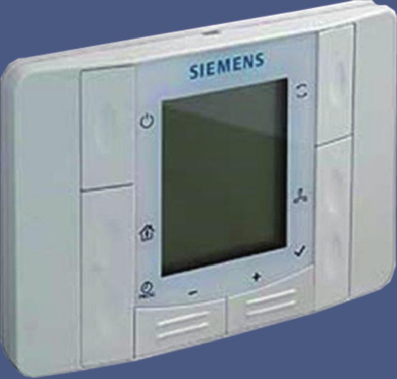
2 Use The room unit is intended for basic users control and monitoring of the function of Mandík air conditioning units incl. basic parameters. The measurement of temperature of the room, where the room unit is installed, is integrated. Up to two room units can be connected to the Mandík measurement and control system. The room unit is not intended for setting the configuration parameters. The configuration parameters are set on the control panel of Climatic controller or through the web viewer of the computer connected to the Climatix controller installed in the switchboard with OS designation. The parameter setting is described in the document Detailed instruction for control through HMI Climatix. Characteristics The room unit is intended for semi-flushed surface mounting with a recessed installation box. The cable entry is through the rear of the unit. The unit consists of a front cover with electronics and a rear cover. The rear cover can be removed after loosening the safety mechanism. The front cover comprises a printed-circuit board and a room temperature sensor, an LCD panel and key buttons for selection of operating mode, temperature set-up, time setting and fan speed. The rear cover includes terminal connections for connection of twowire communication conductors. Both covers are made of plastic material. Cover removal The cover removal is described in the Installation manual that forms a part of the package. Control buttons and display Buttons No. Icon Name Function 1 ON/OFF 2 Occupancy 3 Parameters 4 Minus 5 Plus 6 Info 7 Fan 8 Mode Button for switching on or off the air conditioning unit. The button enables to switch on/off temporarily the occupancy mode in the time programme. The button enables to change the required temperature values or to quit the viewing of the actual temperatures. The button for changing the set-point of the selected parameter or temperature. The button for changing the set-point of the selected parameter or temperature. By pressing the button the viewing of current temperatures is activated or the possibility to change the required temperatures is quitted. The button is used to set the fan speed within the pre-set fan speeds for the modes Economy and Comfort. Using this button you can switch between the modes Time Schedule, Economy and Comfort, when the air conditioning unit is on. 2 / 12
3 Icons No. Icon Meaning Temperature in C (resolution 0.1 C). 1 The temperature can be adjusted with a resolution of 0.5 C. 2 Time 3 Fan speed. Number of stages 4 Weekday indicator in the lower part of the display. 5 6 Modes are switched off the air conditioning unit is off or it works in the complementary mode of room frost protection based on parameters in the room unit setting ). Automatic change of air conditioning unit modes according to the time schedule. It is not used, if no time schedule is available. 7 Economy mode - the air conditioning unit is on. 8 Comfort mode - the air conditioning unit is on Cooling is on; the flashing icon indicates a cooling failure. Heating is on; the flashing icon indicates a heating failure. Humidifying is on; the flashing icon indicates a humidifying failure. Complementary mode is on; the flashing icon indicates the complementary mode failure. 13 Fans are on; the flashing icon indicates a fan failure Operation with the use of power-saving function of energy recovery and air mixing. The flashing icon indicates the failure of generator energy saving function. Failure indication. The flashing icon indicates a new failure. The lighting icon indicates an extinct failure not confirmed/quitted by the operator or a failure that has been quit by the operator, but has not extinguished yet. Further details are given by flashing icons. The specific failure is displayed on the control panel of the Climatix controller or web viewer of the computer connected to the Climatix controller in the OS-designated switchboard. Indication of non-standard operation or status of the air conditioning unit. The lighting icon indicates a nonstandard operation, so-called non-serious failure (clogged filter, thawing air conditioning/condensing unit, etc.). The flashing unit indicates blocking of the air conditioning unit operation due to non-meeting of operating conditions (low temperature of heating water, etc.). The particular information is displayed on the control panel of the Climatix controller or web viewer of the computer connected to the Climatix controller in the OS-designated switchboard. 3 / 12
4 Function description Starting the air conditioning unit Switch the air conditioning unit on or off by pressing the button OFF/ON. When the air conditioning unit is switched on, the unit is in condition before last switching off (Time Schedule, Economy or Comfort). This condition is indicated by combination of icons 6, 7 and 8. After switching off the air conditioning unit, the unit is either turned off or it changes over into complementary mode of room frost protection. This status is indicated by icon 5. In the default setting of the complementary frost protection mode, the air conditioning unit is turned off. Only if the room temperature falls below 5 C, the air conditioning unit is switched on until the room temperature higher than 5 C is reached. If the room temperature sensor is not used, it can be substituted by a temperature sensor of the supplied or exhausted air. The substitution is performed in configuration parameters *). Operating mode selection After switching on the air conditioning unit by the OFF/ON button and by pressing the button Mode the air conditioning unit switches between the modes Time schedule, Economy and Comfort in cycles. If no time schedule is set, the air conditioning unit switches only between the modes Economy and Comfort. The currently selected mode is indicated on the display by the combination of the relevant icons 6, 7 and 8. Operating mode Economy In the mode Economy the air conditioning unit is heating or cooling so that the temperature required for this Economy mode is reached. This mode is indicated on the display by the icon 7. The default setting for this mode is 18 C. The current temperature can be changed temporarily by the Plus or Minus buttons. The temperature setting can be changed by the Parameters button. The fan speed is preset in the configuration parameters of this mode *). The speed can be increased by the button Fans in six steps up to the speed corresponding to the Comfort mode. This setting is possible only if the configuration parameters are adjusted for fan button control *). Operating mode Comfort In the mode Comfort the air conditioning unit is heating or cooling so that the temperature required for this Comfort mode is reached. This mode is indicated on the display by the icon 8. The default setting for this mode is 22C. The current temperature can be changed temporarily by the Plus or Minus buttons. The temperature setting can be changed by the Parameters button. The fan speed is preset in the configuration parameters of this mode *). The speed can be reduced by the button Fans in six steps down to the speed corresponding to the Economy mode. This setting is possible only if the configuration parameters are adjusted for fan button control *). 4 / 12
5 Complementary modes Complementary modes are activated when the operating modes Comfort and Economy are deactivated. Upon activation of the complementary mode, the air conditioning unit is switched on so that the quality of the air conditioning unit operation is improved with regard to the conditioned room, i.e. to avoid unnecessary cooling down or overeating of the conditioned room in the period when the operating modes Economy and Comfort are deactivated. The complementary modes can also function as protection of the equipment and the conditioned room. These complementary modes are activated in the configuration parameters *). Time schedule The selection of Time Schedule is indicated on the display by the icon 6. When you select this mode, so the controller switches between the modes according to the time schedule adjusted. The modes Economy and Comfort are again indicated by the icons 7 and 8 together with the icon 6. The switched-off modes (complementary frost protection mode) are indicated by icon 6 only. Temporary change of the modes in the time schedule can be performed by the Occupancy button. The temporary change is indicated by the flashing icon 6 and the icon of the active mode. This temporary change will last until the next change of the mode according to the time schedule. The fan speed can be changed in the time schedule by the button Fans in six steps within the speed ranges preset for the modes Economy and Comfort, if the configuration parameters enable to control the speed from the room unit. Temperatures for the modes Economy and Comfort controlled according to the time schedule cannot be changed from the room unit as they are also controlled according to the time schedule or configuration parameters *). The time schedule can be programmed for the whole year. The individual points of the time schedule are set on the control panel of the Climatix controller or through the web viewer of the computer connected to the Climatix controller in the OS-designated switchboard. The time schedule setting is described in the document Detailed instruction for control through HMI Climatix. Description of individual functions Setting the required temperature for Comfort mode There are two ways to set up the temperatures required for the Comfort mode outside the time schedule (only the icon 8 is on). Temporary temperature setting, until the next change of mode, or permanent temperature setting. The temporary temperature setting is made by the buttons Plus or Minus when the Comfort mode is active. To set the temperature permanently, press the button Parameters, an image with the parameter Comf and the flashing required temperature for the Comfort mode are displayed. Change the temperature to the required value using the Plus or Minus buttons. The setting is quitted by the Info button or automatically after 30 seconds of inactivity. 5 / 12
6 Setting the required temperature for Economy mode There are two ways to set up the temperatures required for the Economy mode outside the time schedule (only the icon 7 is on). Temporary temperature setting, until the next change of mode, or permanent temperature setting. The temporary temperature setting is made by the Plus or Minus buttons when the Economy mode is active. To set the temperature permanently, press 2x the button Parameters, an image with the parameter Econ and the flashing required temperature for the Economy mode are displayed. Change the temperature to the required value using the Plus or Minus buttons. The setting is quitted by the Info button or automatically after 30 seconds of inactivity Information viewing By pressing the Info button the image with the information values from the connected temperature sensors, air humidity or quality sensors occurs in dependence on the current configuration of the air conditioning unit. These values are displayed in cycles and the next value is displayed by repeated pressing the Info button. The values below are available: Zad required temperature C Dod temperature of the air supplied C Pro room temperature C Ven outdoor temperature C VoT temperature of heating water on the return pipe C VoC temperature of the cooling water on the return pipe C Spa temperature of the waste gases of gas heating C Odv temperature of exhaust air C Rek temperature behind the recuperator C Chl temperature behind the cooler C Ohr temperature behind the heater C Vlh air humidity % Kval air quality % The information viewing is quitted by the Parameters button or automatically after 30s of inactivity. Fan speed The fan speed is set by the repeated pressing the button Fans provided that the configuration parameters *) are preset to enable the control of the fan speed from the room unit. The fan speed can be set in six steps indicated on the display within ranges preset for the modes Economy and Comfort. The fan speed for the individual modes is set in the configuration parameters *). If the fan speed control from the room unit is not enabled, then the icon 3 shows the fan speed determined by the Climatix controller according to the current operating mode. The fan speed setting is purposeful only if the fan motors are controlled by the frequency converter or if EC motors are used. The fan operation is indicated on the display by the icon 13, in case of fan failure the icon is flashing. 6 / 12
7 Button locking The button locking is used to protect the setting from the unauthorized intervention by a non-instructed person. The lock is activated by pressing and holding the button Occupancy (for approx. 8s). The lock is indicated on the display by the notice LOCK. In this condition, no changes of values or modes are possible. When you press any button on the display, the notice LOCK occurs on the display. The buttons are unlocked again by pressing and holding the button Occupancy. The unlocking is indicated on the display by the notice OPEN. Room unit reset The room unit can be reset by pressing and holding the button Fan (approx.8s). Upon pressing this button, the display goes out and new initialization is started and the communication is resumed. System time The correct system time setting is necessary for the correct function of the air conditioning unit according to the time schedule. The system time setting is activated by pressing and holding the button Parameters. The time can be changed by the Plus or Minus buttons and confirmed by the Info button. The setting sequence of the values of the system time changes in cycles and is as follows: Hour minutes time format year month day hour The setting is quitted by pressing the button Parameters or after inactivity exceeding 30s. The system time can also be set on the control panel of the Climatic controller or through the web viewer of the computer connected to the Climatix controller in the OS-designated switchboard. The system time setting is described in the document Detailed instructions for control through HMI Climatix. Communication The parameters of the Climatix controller are factory-preset so that communication is established as soon as the room unit is connected to the controller. The parameter initialization is indicated on the display by the letter P-. The communication parameters can be set both on the Climatix controller and the room unit. When two room units are used, it is necessary to change the parameter 007 in one of the room units. The access code is 0000 and is preset. The communication parameter can be changed as follows: Press the buttons OFF/ON, Mode, Plus and Minus at the same time to activate the entry of the four-digit access code. The cursor is blinking at the first position and by repeated pressing the Mode button the first flashing parameter 001 is displayed. Using the Plus and Minus buttons select the flashing parameter to be changed and confirm the setting by the Mode button. The cursor jumps to the value below, which can be also changed by Plus and Minus buttons. The setting is again confirmed by the Mode button and the setting of all communication parameters is quitted by repeated pressing the OFF/ON button. 7 / 12
8 Number Parameter description KNX communication Communication is functioning -OK Communication is not functioning -NG Individual address - (X.1.1) The range is 0 to 15. The preset value is 0. Individual address - (1.X.1) The range is 0 to 15. The preset value is 1. Individual address - (1.1.X) The range is 1 to 252. The preset value is 1. Byte address - (X.1.1) The range is 1 to 126. The preset value is 5. Room address (1.X.1) The range is 1 to 14. The preset value is 1. Zone address - (1.1.X) The range is 1 to 15. The preset value is 1. Enable the network failure detection Enables or disables the detection of the communication network failure. The failure is indicated by a blinking notice NET. Automatic assignment of the individual address 0 the room unit uses the defined fixed individual address. 1 the room unit generates automatically the individual addresses. Note *) The configuration parameters are set on the control panel of the Climatix controller or through the web viewer of the computer connected to the Climatix controller in the OS-designated switchboard. The parameter setting is described in the document Detailed instructions for control through HMI Climatix. 8 / 12
9 Designing The room unit is supplied from the connected controller through 2- wire interface (low voltage, SELV). The room unit must be connected to the Climatix controller by twowire twisted pair cable. It is possible to use unshielded conductors. Mounting instructions The device is suitable for semi-flush mounting with a recessed installation box. The device must not be mounted into recesses, shelves, behind curtains or doors or above or near the direct heat sources. Avoid direct sun and draught. The conduit must be sealed on the device side as an air stream along the conduit can affect the sensor readings. The permissible ambient conditions for mounting the device must be observed. The mounting instructions are enclosed with the device. Installation Local installation regulations must be observed. STOP Warning The equipment is not protected against accidental connection to AC 230 V. Commissioning Device connection After interruption of the connection to the 2-wire interface, the communication is re-established only if the room units send a query about the controller address. For QAA07, the time cycle for querying is: 250 ms Step Function Description 1 LCD test All display segments are displayed for approx. 2 seconds 2 Identification of the connected controller 3 Ready for operation The room unit establishes contact with the connected Climatix controller Disposal The device contains electrical and electronic components and must not be disposed as domestic waste. The valid local legal regulations are to be observed! 9 / 12
10 Technical data Supply voltage Operating voltage DC V the room unit is supplied from the connected controller via 2-wire interface (SELV, extra low voltage according to HD384) Power consumption (from the controller) Max VA Operating conditions Temperature sensor Measuring element NTC resistance sensor Measuring range C Response 10 min Accuracy (5 30 C) 1.0 K Accuracy (25 C) 0.5 K Display Type LCD Display function - Requirement adjustment - Operating mode selection - Manually selected fan speed - Control sequence - Time and weekday - Parameter setting (only when selected) Interface Type of interface between the 2-wire interface connection controller and the room unit Voltage signal, logic 0 < 5 V Voltage signal, logic 1 > 7 V Maximum number of controllers 8 Baud rate 4.8 kbps Cable connection Connection terminals (screw terminals) Solid or stranded conductors mm2 Cable type 2-wire, twisted pair, unshielded Max. distance between two units 75 m Degree of cover protection Max. total busbar length 125 m Protection according to EN IP 30 Protection class Protection class III Ambient conditions IEC Operation Transport Industry standards Ambient air class 3K3 class 2K3 Temperature C C Humidity < 85% r.h. < 93% r.h. Mechanical conditions class 3M1 class 2M2 Electromagnetic compatibility Immunity for residential, commercial and light-industrial environments EN :2001 Emission standard for residential, commercial and light-industrial environments EN :2001+A11:2004 CE conformity 10 / 12
11 Make yourself familiar with the requirements for CE marking as defined in the EMC directive 2004/108/EC Dimensions See: Dimensions Colour Front cover, rear cover, buttons RAL9003 white Weight Without packaging 0.12 kg 11 / 12
12 3982M M Z07 Electric connection Terminal layout: 2-wire interface, power supply device power supply, data (positive) device power supply, data (negative) Negative Positive Dimensions (units: mm) Connection of the room unit to the Climatix controller Climatix controller Process Bus Room unit 1 Room unit 2 12 / 12
QAW70. Room Unit. Siemens Building Technologies HVAC Products. for use with heating controllers
 1 37 Room Unit for use with heating controllers Digital, multi-functional room unit for the convenient operation of heating controllers from the living room. A setpoint knob and an economy button allow
Room Temperature Sensors
 1 749 1749P01 QAA201 Symaro Room Temperature Sensors QAA201 Active sensors for acquiring the room temperature Operating voltage AC 24 V or DC 135 35 V Signal output DC 010 V or 420 ma Use In heating, ventilation
Semi flush-mount room thermostat
 3 078 Semi flush-mount room thermostat for CAV / VAV heating and cooling systems for AHU systems for universal heating and cooling systems RDU340 Modulating PI control Control depending on the room or
Semi flush-mount room thermostat with KNX communications For VAV heating and cooling systems
 s 3 72 Semi flush-mount room thermostat with KNX communications For VAV heating and cooling systems RDU34 KNX bus communications (S-mode and LTE mode) Backlit display PI / P control Outputs for DC 0 0
QAW70. Room Unit. Building Technologies. for use with heating controllers
 1 637 Room Unit for use with heating controllers QAW70 Digital, multi-functional room unit for the convenient operation of heating controllers from the living room A setpoint knob and an economy button
Room thermostats with LCD for wall mounting
 s 3 181 RDG100 / RDG110 RDG140 / RDG100 RDG100/H Room thermostats with LCD for wall mounting for fan coil unit applications for universal applications for use with compressors in dx type equipment RDG1
Semi flush-mount room thermostats
 s 1 440 RDD310/EH RDE410/EH Semi flush-mount room thermostats for control of electric floor heating systems and for hydronic zone control systems RDD310/EH RDE410/EH Key features of both types of thermostats:
Room thermostat with Auto Timer, Option External Input
 s 1 422 Room thermostat with Auto imer, Option External Input for heating systems RDE100.. Room temperature control 2-position control with On/Off output for heating Comfort, Economy, Auto timer and Protection
Fume Hood Operating Display Panel
 Desigo TRA Fume Hood Operating Display Panel QMX3.P87 The Operating Display Panel (ODP) is the interface between the operator and the DXR Fume Hood Controller (FHC). LCD display for volume flow setpoint,
Preliminary Release. Room Temperature
 3 057 Preliminary Release RDF110 RDF110/IR RDF110.2 RDF110.2/IR Room Temperature Controllers with LCD for 2-pipe fan coil units for compressors in DX-type equipment RDF110 Output for an on / off valve
Room Temperature Controller
 3 22 Room Temperature Controller for two-pipe fan coil units with electrical heater RCC2 Outputs for on / off valve actuator and electrical heater Output for three-speed fan Control depending on the room
RVL480. Heating Controller
 2 540 Heating Controller RVL480 Multifunctional and communicating heating controller for use in residential and non-residential buildings. Suited for heating circuit control, boiler temperature control
Room Sensors. Building Technologies HVAC Products ... Symaro. for relative humidity (high accuracy) and temperature
 and temperature") 1 858 1858P01 1858P02 1859P02 Symaro Room Sensors for relative humidity (high accuracy) and temperature AQF3150 QFA31 Use Operating voltage AC 24 V / DC 1353 Signal output DC 010 V / 4 20 ma for r h and
1 858 1858P01 1858P02 1859P02 Symaro Room Sensors for relative humidity (high accuracy) and temperature AQF3150 QFA31 Use Operating voltage AC 24 V / DC 1353 Signal output DC 010 V / 4 20 ma for r h and
for relative humidity and temperature
 1 861 1861P01 Duct sensor for relative humidity and temperature QFM65 Operating voltage AC 24 V Signal output DC 0...10 V for relative humidity and temperature Measurement accuracy ±3 % r. h. within the
RVL481. Heating Controller. including d.h.w. heating
 2 541 Heating Controller including d.h.w. heating RVL481 Multifunctional and communicating heating controller for use in residential and non-residential buildings. Suited for heating circuit control with
for relative humidity and temperature with calibration certificates
 1 859 1859P01 1859P02 QFA4160 AQF4150 Symaro Room Sensor for relative humidity and temperature with calibration certificates QFA4160 Operating voltage AC 24 V or DC 13.5...3 Signal output DC 0...10 V for
Duct Air Quality Sensors
 1 962 QPM2102D QPM2160D, QPM2162D QPM2100, QPM2102 QPM2160, QPM2162 Duct Air Quality Sensors QPM21 With maintenance-free CO 2 sensing element based on optical infrared absorption measurement (NDIR 1 )
Room Air Quality Sensors
 1 961 1961P1 1961P2 QPA2 QPA2D Room Air Quality Sensors QPA2 With maintenance-free photoacoustic CO 2 sensing element and depending on the type of sensor VOC 1) sensing element, based on a heated tin dioxide
QFM21... Siemens Building Technologies HVAC Products. Symaro Duct Sensors. for relative humidity and temperature
 1 864 1864P01 Symaro Duct Sensors for relative humidity and temperature QFM21... Use Type summary Operating voltage AC 24 V or DC 13.5...3 Signal output DC 0...10 V for relative humidity Signal output
Room thermostat with Auto Timer, Option External Input
 s 1 422 Room thermostat with Auto imer, Option External Input for heating systems RDE100.. Room temperature control 2-position control with On/Off output for heating Comfort, Economy, Auto timer and Protection
Room air quality sensors
 1 961 1961P01 QPA20 QPA20 D 1961P02 Room air quality sensors QPA20 Use With maintenance-free CO 2 sensing element based on optical infrared absorption measurement (NDIR 1) ) and depending on the type of
DOCUMENTATION IPS640
 DOCUMENTATION IPS640 TECHNICAL AND APPLICATION DESCRIPTION Authors: Nebojša Božič, Peter Hauner Last modification: 2017-01-25 2001-2017 Apricum d.o.o. Mažuranićeva 4, 21312 Podstrana, Hrvatska Details,
Room Temperature Controller with LCD
 3 053 Room Temperature Controller ith LCD for 4-pipe fan coil units for compressors in DX type equipment ith reversing valve Outputs for on / off valve actuators Outputs for 2-stage compressor ith reversing
DOCUMENTATION IPS640
 DOCUMENTATION IPS640 TECHNICAL AND APPLICATION DESCRIPTION Authors: Nebojša Božič, Peter Hauner Last modification: 2018-07-06 2001-2018 Apricum d.o.o. Mažuranićeva 4, 21312 Podstrana, Hrvatska Details,
Duct Sensors. Siemens Building Technologies HVAC Products. Symaro. for relative humitidy (high accuracy) and temperature
 and temperature") 1 882 1882P01 Symaro Duct Sensors for relative humitidy (high accuracy) and temperature QFM31 Use Examples Operating voltage AC 24 V / DC 1353 Signal output DC 010 V / 4 20 ma for relative humidity and
1 882 1882P01 Symaro Duct Sensors for relative humitidy (high accuracy) and temperature QFM31 Use Examples Operating voltage AC 24 V / DC 1353 Signal output DC 010 V / 4 20 ma for relative humidity and
RVL479. Heating Controller. for use with a partner unit
 2 543 Heating Controller for use with a partner unit RVL479 Communicating heating controller for use in residential and non-residential buildings. For exclusive use on the bus together with heating controllers
Room Temperature. for 2-pipe fan coil units for compressors in DX type equipment
 3 057 RDF110 RDF110/IR RDF110.2 RDF110.2/IR Room Temperature Controllers with LCD for 2-pipe fan coil units for compressors in DX type equipment RDF110 Output for on / off valve actuator or 1-stage compressor
QFM21... Duct sensors. Symaro. for relative humidity and temperature
 1 864 1864P01 Symaro Duct sensors for relative humidity and temperature QFM21... Operating voltage AC 24 V / DC 13.5...35 V Signal output DC 0...10 V / 4 20 ma for relative humidity Signal output DC 0...10
for relative humidity and temperature
 1 860 1860P01 Duct sensor for relative humidity and temperature QFM651 Operating voltage AC 24 V Signal output DC 010 V for relative humidity Signal output L&S Ni 1000 (passive) for temperature Measurement
QFM21... Duct Sensors. Building Technologies HVAC Products. Symaro. for relative humidity and temperature
 1 864 1864P01 Symaro Duct Sensors for relative humidity and temperature QFM21 Operating voltage AC 24 V / DC 13535 V Signal output DC 010 V / 420 ma for relative humidity Signal output DC 010 V / 420 ma
RVP331. Heating Controller for 2 heating circuits, d.h.w. and boiler. Building Technologies HVAC Products
 2 478 Heating Controller for 2 heating circuits, d.h.w. and boiler RVP331 Multi-functional heating controller for use in residential and non-residential buildings Suitable for weather-compensated flow
Room thermostat with Auto Timer, Option External Input
 s 1 422 Room thermostat with Auto imer, Option External Input for heating systems RDE100.. Room temperature control 2-position control with On/Off output for heating Comfort, Economy, Auto timer and Protection
Smart Thermostat RDS110
 Smart Thermostat RDS110 To control heating applications in apartments, single family homes, dormitories, and other residential as well as commercial spaces. Backlit, auto-dimming 90 mm color LCD touch
Wall-mounted room thermostat with LCD
 3 182 Wall-mounted room thermostat with LCD for VAV heating and cooling systems RDG400 Modulating PI control Control depending on the room or the return air temperature Output for DC 0 10 V actuator and
QPM21 Series Duct CO 2 and Air Quality Sensors
 Document No. CE1N1962 QPM21 Series Duct CO 2 and Air Quality Sensors Description Features Application The Carbon Dioxide (CO 2 ) Duct Sensors are directly wired to the controller via twisted pair and/or
PRELIMINARY EDITION
 3 131 PRELIMINARY EDITION 14.01.2003 Synco 700 Heating Controllers Heating controller for medium-size and large buildings. The is used as a heating circuit or primary controller. The controller is supplied
Control solutions Biofloor
 TEF234 Electronic room thermostat with display 230V & 24V COMAP proposes a new control system for heating and cooling underfloor. Consisting of a 6 or 10- channels controller (MCF234), analogic (TAF234)
Room Unit. Building Technologies SYNERGYR
 2 812 SYNERGYR Room Unit QAW20 Programmable room unit for operation of the SYNERGYR control and billing system The unit's setting knob and economy button make it very easy to control the supply of heat
Heating Controller for 2 heating circuits, d.h.w. and boiler, communicating
 2 477 Heating Controller for 2 heating circuits, dhw and boiler, communicating RVP330 Multi-functional heating controller for use in residential and non-residential buildings Suitable for weather-compensated
GreenCon On/Off Room Thermostat
 Description Features: Scandinavian design with white backlight; User-friendly interactive interface; Room temperature display and settings; 12 or 24 hour clock display and settings; Three-speed manual/automatic
GreenCon On/Off Room Thermostat
 Description Features: Scandinavian design with white backlight; User-friendly interactive interface; Room temperature display and settings; 12 or 24 hour clock display and settings; Three-speed manual/automatic
Connections, displays and operating elements C D E G H. Installing the control unit
 1 2 3 GB Control unit 0-10 V REG-K/3-gang with manual mode Operating instructions Art. no. MTN646991 ¼ DANGER Risk of fatal injury from electrical current. All work on the device should only be carried
RVL470. Heating Controller. Use. Functions. Series B
 2 522 Heating Controller Series B RVL470 Multifunctional heating controller for use in residential and non-residential buildings; suitable for weather-dependent flow temperature control of heating zones
ESRTPRF. Wireless Programmable Room Thermostat, with Delayed & Optimum Start. User and Installation Instructions M/A MANUAL
 M/A MANUAL ESRTPRF Wireless Programmable Room Thermostat, with Delayed & Optimum Start User and Installation Instructions INDEX User Instructions What is a Programmable Room Thermostat? 1 Introduction
Installation and Operating Manual
 Installation and Operating Manual SR868C6 System Regulator for Solar Thermal Systems Display Panel Illustration Pos. Button on display panel Button description 1 Green lamp Power indication lamp 2 On/Off
QFM21... Duct Sensors. Siemens Building Technologies HVAC Products
 For latest prices and delivery to your door visit MyTub Ltd - 0845 303 8383 - wwwmytubcouk - info@mytubcouk 1 864 1864P01 Symaro Duct Sensors for relative humidity and temperature QFM21 Use Operating voltage
DT92 WIRELESS DIGITAL ROOM THERMOSTAT FEATURES PRODUCT SPECIFICATION SHEET
 DT92 WIRELESS DIGITAL ROOM THERMOSTAT PRODUCT SPECIFICATION SHEET The new DT92 family of wireless digital room thermostats is a range of market leading products designed to provide comfort with economy
RVA /109. Heating Circuit ZONE Controller. Instructions for the INSTALLER
 Heating Circuit ZONE Controller RVA 46.531/109 Zonal temperature controller for control of a lowtemperature heating system, for use with condensing gas boilers Instructions for the INSTALLER INDEX Page
Room thermostat with 24-hour time switch and large LCD
 Room thermostat with 24-hour time switch and large LCD RDJ100 Programmable, for heating systems Operating modes: Automatic, Comfort, Energy saving, and Frost protection Large LCD display Battery powered:
Room Temperature Controllers
 3 021 Room Temperature Controllers for two-pipe fan coil units RCC10 Output for on / off valve actuator Outputs for three-speed fan Control depending on the room or return air temperature (RCC10) Automatic
RVP310. Heating Controller. Building Technologies HVAC Products
 2 475 Heating Controller RVP310 Multifunctional heating controller for use in residential and non-residential buildings; suitable for weather-dependent flow temperature control of heating zones with or
Duct Temperature Sensors
 1 762 1761P03 1762P01 Mounting flange AQM630 QAM21 Symaro Duct Temperature Sensors QAM2161040 QAM2171040 Active sensors for acquiring the air temperature in air ducts AC 24 V or DC 13535 V Signal output
Flush-mounted room thermostat
 3 078 Flush-mounted room thermostat, for CAV / VAV heating and cooling systems, for AHU systems, for universal heating and cooling systems RDU340 Modulating PI control Control depending on the room or
Instruction FH-CWP Thermostat
 Instruction FH-CWP Thermostat Index Instruction FH-CWP Thermostat 1. Functional Overview.......................... 3 2. Mounting..................................... 4 3. Installation....................................
RVL472. Heating Controller. Building Technologies HVAC Products. Series C. including d.h.w. heating
 2 526 Heating Controller including dhw heating Series C RVL472 Multifunctional heating controller for use in residential and non-residential buildings Suited for: Heating zone control with or without room
INSTRUCTION MANUAL REMOTE CONTROL DEVICE EASYREMOTE
 INSTRUCTION MANUAL REMOTE CONTROL DEVICE EASYREMOTE Technical features Guide to LCD symbols Guide to keys Technical features Supply by communication bus Number of temperature levels 2 (DAY / NIGHT) Temperature
Room thermostat with Auto Timer, independent DHW
 s 1 423 Room thermostat with Auto Timer, independent DHW for heating systems RDE100.1 DHW Room temperature control 2-position / TPI control with On/Off output for heating Optimum Start / Stop Comfort,
Semi flush-mount communicating room thermostats
 s 3 7 RDF30, RDF600KN RDF30.50, RDF600KN/S RDF30.50H Semi flush-mount communicating room thermostats For 2-pipe, 2-pipe with electric heater, and 4-pipe fan coil units For use with compressors in DX type
Wireless room thermostat with LCD
 s 1 424 RDD100.1RF RCR100RF Wireless room thermostat with LCD for heating systems RDD100.1RFS Roomom temperature control Comfort, Economy and Protection mode 2-position control with On/Off control output
Universal Dimmer N 528D01, 2 x 300VA, AC 230 V 5WG DB01
 Gamma instabus Universal Dimmer N 528D01, 2 x 300VA, AC 230 V 5WG1 528-1DB01 Technical Product Information Universal Dimmer for switching or dimming of dimmable lamps Supports dimmable lamps including
Room Temperature Sensor
 2 701 Synco 900 Room Temperature Sensor QAA910 Wireless room temperature sensor for acquiring the room temperature RF communication based on KNX standard (868 MHz, unidirectional) Battery-powered by commercially
Flush-mounted room thermostats
 s 3 RDF300, RDF300.02, RDF340 RDF600 076 RDF400.01 RDF600 Flush-mounted room thermostats RDF300 RDF340 RDF400 for 2-pipe, 2-pipe with el. heater and 4-pipe fan coil units for use with compressors in DX
CRX Single Zone Wireless Controller. Installation and User Guide. 1. Getting to know your CRX2 wireless controller
 Please read this guide carefully and retain for future use and maintenance. CRX2-01 Single Zone Wireless Controller Installation and User Guide 1. Getting to know your CRX2 wireless controller An illustration
Quickheat 30 weather compensated boiler control
 Quickheat 0 weather compensated boiler control A compact and sophisticated heating controller The compact KM controller is designed for the control of fan assisted boilers with modulating burners. The
REA22 Room Temperature Controller
 REA22 Room Temperature Controller Basic Documentation Issue: 2.0 Controller series: A CE1P2276E 31.03.1999 Siemens Building Technologies Landis & Staefa Division Siemens Building Technologies Ltd. Landis
Indoor Air Quality Controller
 s 1 571 Indoor Air Quality Controller QPA84 With integrated VOC (Volatile Organic Compounds) sensor Operating voltage AC 230 V, Two-position output (non-potential-free relay contact) Use In ventilation
Room thermostats with LCD RDD100..
 s 1 420 Room thermostats with LCD RDD100.. for heating systems Roomom temperature control Comfort, Economy and Protection mode 2-position control with On/Off control output Adjustable commissioning and
Self-learning Room Temperature Controller
 2 257 Self-learning Room emperature Controller 5 operating modes and menu selection via roller selector REV16 Mains-independent room temperature controller Straightforward, self-explanatory menu selection
Room Temperature Controller
 3 022 Room Temperature Controller for two-pipe fan coil units with electrical heater RCC20 Outputs for on / off valve actuator and electrical heater Output for three-speed fan Control depending on the
Digital Room Thermostat for Heating Applications with 7-Day Time Program
 Specification Digital Room Thermostat for Heating Applications with 7-Day Time Program CONFORT CRONO (RDE100.1-EQ*) * internal model name Two-position control with ON / OFF relay output for heating Operating
Technical Instructions Document No. CE1N1961 March 17, Room CO 2 and Air Quality Sensors. Description. Features. Application
 Document No. CE1N1961 QPA20 Room CO 2 and Air Quality Sensors Description The Q-Series Room Carbon Dioxide (CO 2 ) and Air Quality Sensors are especially suited for applications where precise, stable carbon
Use. In ventilating and air conditioning plants to enhance room comfort and to optimize energy consumption by providing demand-controlled ventilation.
 1 958 CO 2 /VOC Sensors QPA63 QPA631 QPA632 Sensors designed for sensing indoor air quality in rooms or air ducts; microprocessor-based units consisting of a selective photo-acoustic CO 2 sensor and a
Zone Terminal, 2-fold, FM MT/U , GH Q R0111
 , GH Q631 0060 R0111 SK 0001 B 01 The zone terminal is used for the monitored connection of detectors from security techlogy on the EIB. The device is installed in conventional switch boxes (Ø 55 mm).
L. Terminal block Connecting Label:
 TABLE OF CONTENT A. Installation and Mounting.. 3 1. Installation 3 2. Wiring... 4 3. Mounting.. 5 B. Key Interface. 7 C. LCD Interface...8 D. Start/Reset...9 E. Operation Mode.10 F. Time Setting Mode.11
Installation and user manual
 Installation and user manual Please read carefully and retain for future reference Models EcoHeat: C3, C5, C6, C8, C9, C11, C12 Rev.1_09-07-15 Page 1 Table of Contents 1 IMPORTANT: WARNINGS 1.1 GENERAL
Operating instructions
 MA00929301 09/2015 Operating instructions ED10429002 ESYLUX GmbH An der Strusbek 40 22926 Ahrensburg Germany info@esylux.com www.esylux.com 1 Table of contents 1 Using the manual 8 2 Safety instructions
SCHMIDT LED Measured Value Display MD Instructions for Use
 SCHMIDT LED Measured Value Display MD 10.010 Instructions for Use Table of Contents 1 Important Information... 3 2 Application range... 4 3 Mounting instructions... 4 4 Electrical connection... 6 5 Signalizations...
LCF Touch (from firmware version 1.7)
") LCF Touch (from firmware version 1.7) Electronic Fan Coil Thermostat with Touch Display (Flush mounting) Datasheet Subject to technical alteration Issue date: 26.1.216 Application Modern design flush mounting
LCF Touch (from firmware version 1.7) Electronic Fan Coil Thermostat with Touch Display (Flush mounting) Datasheet Subject to technical alteration Issue date: 26.1.216 Application Modern design flush mounting
EUROSTER 11Z CENTRAL HEATING / UTILITY HOT WATER PUMP CONTROLLER
 EUROSTER 11Z USER MANUAL 1 EUROSTER 11Z CENTRAL HEATING / UTILITY HOT WATER PUMP CONTROLLER MANUFACTURER: P.H.P.U. AS, Polanka 8a/3, 61-131 Poznań, POLAND 1 INTRODUCTION Carefully study this user manual
Application description
 Application description Application description Hersteller KNX Touch Control Hager Displays Touch Displays ETS Touch Control Order number Product designation Application programme TP product SWDT03 WDT030
QPA63... CO 2 /VOC Sensors. Siemens Building Technologies HVAC Products
 1 958 1958P01 1958P02 QPA631 QPA632 CO 2 /VOC Sensors QPA63 Sensors designed for sensing indoor air quality in rooms or air ducts; microprocessor-based units consisting of a selective photo-acoustic CO
Dipl.-Ing. W. Bender GmbH & Co. KG Londorfer Str Grünberg Phone: Fax:
 Dipl.-Ing. W. Bender GmbH & Co. KG Londorfer Str. 5 35305 Grünberg Phone: 040 807-0 Fax: 040 807-259 Alarm indicator and test combination MK2430 Remote alarm indicator and test combination with LC display
C-Bus Four Channel General Input Unit Installation Instructions
 C-Bus Four Channel General Input Unit Installation Instructions 5504GI Series REGISTERED DESIGN REGISTERED PATENT Table of Contents Section...Page 1.0 Product Range... 3 2.0 Description... 3 3.0 Capabilities...
C-Bus Four Channel Analogue Output Unit Installation Instructions
 C-Bus Four Channel Analogue Output Unit Installation Instructions 5504AMP Series REGISTERED PATENT Table of Contents Section... Page 1.0 Product Range...3 2.0 Description...3 3.0 Capabilities...3 4.0 Wiring
KNX module for smoke alarm devices Dual/VdS and Q-Label (Order no )
") Product definition KNX module for smoke alarm devices Dual/VdS and Q-Label (Order no 2343 00) Art. no 2343 00 Page 1 of 22 Product definition Table of contents 1 Product definition... 3 1.1 Product catalogue...
Product definition KNX module for smoke alarm devices Dual/VdS and Q-Label (Order no 2343 00) Art. no 2343 00 Page 1 of 22 Product definition Table of contents 1 Product definition... 3 1.1 Product catalogue...
Room controller. RC is a room controller from the Regio Mini series intended to control heating and cooling in a single zone.
 revision 12 2016 RC Room controller RC is a room controller from the Regio Mini series intended to control heating and cooling in a single zone. RC is a room controller in the Regio series. The controller
Remote alarm indicator and test combination MK2430
 Dipl.-Ing. W. Bender GmbH & Co. KG Londorfer Str. 5 35305 Grünberg Tel.: 040 807-0 Fax: 040 807-259 Remote alarm indicator and test combination MK2430 Remote alarm indicator and test combination with LC
testo 316-EX gas leak detector Instruction manual
 testo 316-EX gas leak detector Instruction manual 2 1 Safety and the environment 1 Safety and the environment 1.1. About this document Use > Please read this documentation through carefully and familiarize
LCF Touch Modbus Datasheet Application Security Advice Caution
 LCF Touch Modbus Electronic Fan Coil Thermostat with Touch Display (Flush mounting) Datasheet Subject to technical alteration Issue date: 3.11.214 Application Modern design flush mounting fan coil room
Heating Controller SDC. District Heating Controller DHC 43 OPERATING INSTRUCTIONS
 Heating Controller SDC District Heating Controller DHC 43 OPERATING INSTRUCTIONS Copyright 2002 Honeywell Inc. EN2H-0220 GE51 R0802 SDC / DHC 43 Operating Instructions EN2H-0220 GE51 R0802 Contents SDC
I/A Series 716C 1/16 DIN Temperature Controller
 Product Specifications I/A Series 716C 1/16 DIN Temperature Controller PSS 2C-1B5 A The Foxboro 716C is a powerful compact, 1/16 DIN, microprocessor-based temperature controller that offers a variety of
MC200. Users Instructions. HEATING DIVISION Hort Bridge Ilminster, Somerset TA19 9PS Tel: Fax:
 MC200 Users Instructions BSI Registered Firm HEATING DIVISION Hort Bridge Ilminster, Somerset TA19 9PS Tel: 01460 53535 Fax: 01460 52341 FM 414 Ind. & Comm. Air Heaters; Air Moving Equipment; Flues & Chimneys;
QAF63.2 QAF63.6. Frost sensors for use on the air side. Building Technologies HVAC Products
 1 821 1821P01 Frost sensors for use on the air side Active capillary tube sensor for measuring the lowest temperature within a range of 0 15 C Operating voltage AC 24 V Signal output DC 0...10 V Use On
Room controllers with manual forced ventilation function
 revision 12 2016 RC-O Room controllers with manual forced ventilation function RC-O is a room controller from the Regio Mini series intended to control heating and cooling in a single zone. RC-O is a room
DPB52. True RMS 3-Phase, Multifunction monitoring relay. Benefits. Description
 DPB52 True RMS 3-Phase, Multifunction monitoring relay Description Benefits Measuring Voltage Range. Very wide input voltage range: from 125 to 624V ( 208V 40% to 480 + 30% ). Adjustable Voltage Ranges
AC&R Controller RWR Basic Documentation VR2002 for water to water heat pump units
 AC&R Controller RWR470.10 Basic Documentation VR2002 for water to water heat pump units Table of Contents 1 Summary---------------------------------------------------------------------------------------4
LogTag TICT - is0 Tag
 TICT - is0 Tag Freeze Indicator with display DOCUMENT REVISION 1.0, 4 March 2014 Copyright 2014, LogTag Recorders Limited Contents Contents... 2 Document revision history... 2 Description... 3 Alerts...
Model: 1 Series 12V. Available in: Sapphire Black and Glacier White
 Model: Available in: Sapphire Black and Glacier White 1 Series Table of Contents Product Image Table of Contents What is a Programmable Room Thermostat? Installation Procedure Mode Select Pairing the neohub
ROOM THERMOSTATS KNX BASIC DOCUMENTATION
 ROOM THERMOSTATS KNX BASIC DOCUMENTATION Contents 2 2 2 2 ABOUT THIS DOCUMENT Document use / request to the reader Target audience, prerequisites Glossary 59 59 60 62 63 HANDLING Mounting and installation
XWA11V. Walk-In Temp / Door /Alarm / Light Module
 XWA11V Walk-In Temp / Door /Alarm / Light Module 1. GENERAL DESCRIPTION Model XWA11V, 100x64 mm format, is a microprocessor-based controller, suitable for temperature monitoring and alarming in a walk-in