smart mounting Induction Heater IH 070/090 Bedienungsanleitung Instructions for use Mode d emploi Manuale d istruzioni Manual de instrucciones
|
|
|
- Juliana Tate
- 5 years ago
- Views:
Transcription

1 Induction Heater IH 070/090 Bedienungsanleitung Instructions for use Mode d emploi Manuale d istruzioni Manual de instrucciones


2 2 Induktionsheizgerät IH 070/090 simatec ag
3 Table of contents EU Declaration of conformity 21 Safety recommendations 22 1 Introduction Intended use Principle of operation Distinguishing feature 24 2 Description Components Technical data 25 3 Installation of mains plug 27 4 Preparation for use 28 5 Operation Function of displays Function of buttons TEMP MODE TIME MODE Temperature measurement Change of temperature unit Demagnetisation Power level selection 33 6 Safety features 33 7 Troubleshooting 34 8 Spare parts Induction Heater IH 070/090 simatec ag
4 EU Declaration of conformity simatec ag Stadthof 2, CH-3380 Wangen a. Aare, Switzerland English declares that the Induction Heaters simatherm IH 070/090 are designed and manufactured in accordance with Directive 2006/95/EC of the European Parliament and of the Council relating to electrical equipment designed for use within certain voltage limits Directive 2004/108/EC of the European Parliament and of the Council relating to electromagnetic compatibility and repealing Directive 89/336/EEC The following standards have been applied: EN EN EN EN EN Wangen a. Aare, Mischa N. Wyssmann Managing Director / CEO simatec ag Induction Heater IH 070/090 21
5 Safety recommendations Because the IH 070/090 generates a magnetic field, people wearing a pacemaker must not be within 5m (16ft) of the IH 070/090 during operation. Electronic equipment, such as wristwatches, may also be affected. Follow the operating instructions at all times. Be certain that the voltage supply is correct. Electrical arcing may occur when a potential difference exists between the IH 070/090 and the workpiece. This is not dangerous to human beings and will not cause damage to the IH 070/090 or the workpiece. However, the IH 070/090 must never be used in areas where there is a risk of explosion. Do not expose the heater to high humidity. Never operate the IH 070/090 without a yoke in position. Do not modify the IH 070/090. Use proper handling equipment when lifting heavy workpieces. Avoid contact with hot workpieces. Wear the supplied heatresistant gloves to handle hot workpieces. 22 Induction Heater IH 070/090 simatec ag

6 1 Introduction The simatec IH 070/090 induction heater is designed to heat bearings that are mounted with an interference fit onto a shaft. The heat causes the bearing to expand, which eliminates the need to use force during installation. A 90 C (194 F) temperature difference between the bearing and shaft is generally sufficient to enable installation. At an ambient temperature of 20 C (68 F), the bearing must therefore be heated to 110 C (230 F). English 1.1 Intended use The IH 070/090 has been designed to heat rolling bearings. However, other metal workpieces that form a closed circuit can also be heated. Examples of acceptable workpieces include bushings, shrink rings, pulleys, and gears. All bearings that fit over the inductive coil and between the vertical supports with the top yoke in place can be heated using the IH 070/090. In addition, smaller bearings can be placed over either of the three standard yokes. See the illustrations at the beginning of this manual for examples. 1.2 Principle of operation The IH 070/090 generates heat by means of a large electrical current that is magnetically induced in the workpiece by a coil within the heater. The high voltage, low current electricity flowing through the large number of windings in the inductive coil induces low voltage, high current electricity in the workpiece. Because the workpiece has the electrical characteristics of a coil with a single, short-circuited winding, the high current generates heat within the workpiece. Because the heat is generated within the workpiece, all of the heater components remain cool. simatec ag Induction Heater IH 070/090 23
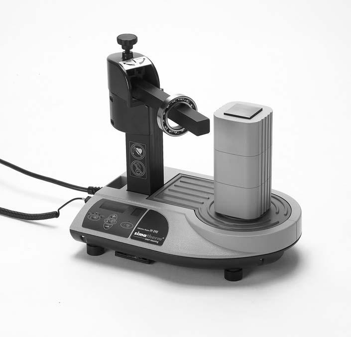
7 1.3 Distinguishing feature The distinguishing feature of the IH 070/090 induction heater is the location of the workpiece at the same position on the core as the inductive coil. This design improves efficiency, resulting in less power consumption and faster heating, which reduces the cost to heat each bearing. 2 Description The operation of the heater is controlled by the internal electronics in either of two modes. The operator can either select the desired temperature of the bearing in TEMP MODE or set the length of time that the bearing will be heated in TIME MODE. The power level can be adjusted in steps of 20% for slower heating of sensitive workpieces (for example, bearings with C1 or C2 clearance). 2.1 Components The IH 070/090 induction heater contains a U-shaped iron core with an inductive coil surrounding one of the vertical supports. Internal electronics control the operation of the heater. A removable yoke on the top of the vertical supports allows the workpiece to be placed onto the heater. The top yoke of the IH 090 is mounted on a swivel. To accommodate smaller workpieces, two smaller yokes are also provided. A temperature probe is also included with the heater. Heat-resistant gloves are also included. 24 Induction Heater IH 070/090 simatec ag
8 2.2 Technical data IH 070 Voltage (± 9%): Recommended circuit protection Power consumption (maximum) 100 V / 50-60Hz V / 60Hz V / 50 60Hz 20A circuit breaker 1.5kVA (100 V / 50-60Hz) 3.7kVA ( V / 60Hz) 3.7kVA ( V / 50 60Hz) Temperature control C ( F) in steps of 1 Probe maximum temperature 250 C (482 F) Time mode 0 60 minutes in steps of 0.1 minute Power range % in steps of 20% Demagnetisation, automatic Residual magnetism < 2A/cm Overall dimensions 420 x 280 x 345mm Area between supports (wxh) 145 x 205mm Coil diameter 115mm Weight (with yokes) 35kg Workpiece maximum weight Bearing 80 kg, solid component 40 kg Maximum heating temperature approx. 400 C (752 F) Standard yoke dimensions 55 x 55 x 275mm (for Ø of 78mm) 28 x 28 x 275mm (for Ø of 40mm) 14 x 14 x 275mm (for Ø of 20mm) English simatec ag Induction Heater IH 070/090 25
9 IH 090 Voltage (± 9%): Recommended circuit protection Power consumption (maximum) 400 V / 50 Hz V / 60 Hz 575 V / 60 Hz 20A circuit breaker 6,4kVA (400 V / 50 Hz) 7,4kVA ( V / 60 Hz) 9,2kVA (575 V / 60 Hz) Temperature control C ( F) in steps of 1 Probe maximum temperature 250 C (482 F) Time mode 0 60 minutes in steps of 0.1 minute Power range % in steps of 20% Demagnetisation, automatic Residual magnetism < 2A/cm Overall dimensions 420 x 280 x 420mm Area between supports 145 x 205mm Coil diameter 115mm Weight (with yokes) 38kg Workpiece maximum weight Bearing 120kg, solid component 60kg Maximum heating temperature approx. 400 C (752 F) Standard yoke dimensions 55 x 55 x 275mm (for Ø of 78mm) 28 x 28 x 275mm (for Ø of 40mm) 14 x 14 x 275mm (for Ø of 20mm) 26 Induction Heater IH 070/090 simatec ag
10 3 Installation of mains plug Due to the many types of mains plugs, no mains plug is supplied with the IH 070/090. A qualified electrician must install a suitable mains plug. The correct supply voltage is shown in section 2.2. The wires should be connected as follows: English IH 070 Colour of IH 070 wire yellow/green brown blue Mains supply terminal Protection earth (PE) Phase 1 (L1) Neutral (N) IH 090 Colour of IH 090 wire yellow/green brown bluw Mains supply terminal Protection earth (PE) Phase 1 (L1) Phase 2 (L2) Connect the IH 090 to only two of the three phases. Verify that the correct circuit breaker is installed. See section 2.2 for circuit breaker specifications. simatec ag Induction Heater IH 070/090 27
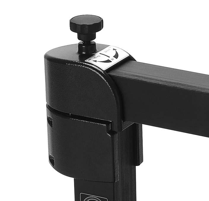
11 4 Preparation for use Place the IH 070/090 in the horizontal position on a stable surface. Connect the mains plug to a suitable mains supply. For the IH 090 only, follow these steps to install the swivel arm: - Attach the protection plate (4) to the side post to prevent damage. - Install the swivel head (1) and the swivel body (2) on the lefthand side post of the heater. - Install the large top yoke (55 x 55mm) in the swivel head. Adjust the swivel body so that there is no visible gap (A) between the side post and the yoke. - Tighten the four screws (3) of the swivel body (maximum torque 5Nm). - Turn the screw (5) on top of the swivel head to position the top yoke. The top yoke must contact as much of the upper surface of the right-hand side post (B) as possible. Noise during operation could indicate that the top yoke is not positioned properly. Special notes for the IH 090: - The yoke support is required when either of the smaller yokes (28 x 28mm or 14 x 14mm) is installed. Install the yoke support and the yoke together in the swivel head. If necessary, rotate the swivel head to provide better access. 28 Induction Heater IH 070/090 simatec ag
12 - Heavy workpieces ( 10 kg/22 lbs) that must be installed on the top yoke should be supported until the yoke is in the correct position on the right-hand side post. The heater may tip over if the workpiece is not supported. - The swivel body (2) can remain on the heater at all times. English For workpieces with an internal diameter large enough to fit over the inductive coil, follow these steps: - Place the workpiece over the inductive coil using appropriate lifting equipment. - For best performance, adjust the position of the workpiece so that the inductive coil is in the centre. - Remove the protective film from the bright underside of the top yoke before the first use. - Position the top yoke so that it completely covers the top of both vertical supports. For workpieces that do not fit over the inductive coil, follow these steps: - Choose the larger of the three yokes that fit through the internal diameter of the workpiece. - If necessary, remove the top yoke from the IH 070/ Verify that the protective film has been removed from the underside of the small or medium yoke if it is to be used for the first time. - Slide the workpiece onto the yoke that you have selected. - Position the yoke on the IH 070/090 with the bright underside resting evenly on the two vertical supports. If you will use TEMP MODE, plug the temperature probe into the connector on the left side of the heater. Place the magnetic end of the probe on the inner ring of the bearing or on the innermost surface of the workpiece. Use the power switch on the left side to switch on the IH 070/090. Observe the self-test of the display and signal tone. simatec ag Induction Heater IH 070/090 29

13 5 Operation 5.1 Function of displays A B A. The main display shows the selected time or temperature for heating. Display Indication t time in minutes C temperature in degrees Celsius F temperature in degrees Fahrenheit B. The power display shows the selected power setting. Display Indication 20% power 40% power 60% power 80% power 100% power 5.2 Function of buttons Button POWER MODE UP (+) DOWN (-) START/STOP Function Press to adjust the power in steps of 20%. The selected power is indicated on the power display. Press to switch between TIME MODE and TEMP MODE. Press to increase the value shown on the main display. Press to decrease the value shown on the main display. Press to start or stop the heater. The LED on the START/ STOP button is lit when the heater is heating and flashes during temperature measurement. 30 Induction Heater IH 070/090 simatec ag
14 5.3 Temp mode If the main display shows t, press MODE to select TEMP MODE. The main display shows C or F in TEMP MODE. The selected temperature is shown on the main display. The default temperature for bearings is 110 C (230 F). If a different temperature is desired, press UP or DOWN to adjust the temperature in steps of 1. It may be desirable to heat bearings to temperatures above 110 C (230 F) for increased mounting time. Consult the bearing specifications to determine the maximum permitted temperature. Always ensure the bearing does not lock due to an excessive expansion of the inner ring compared to outer ring. See section 5.8. All Spherical Roller Bearings (SRBs) are subjected to a special heat treatment. These bearings can be operated at temperatures as high as 200 C (392 F). Heating these bearings above 110 C (230 F) will not cause any damage as long as the bearing is still able to rotate. For other bearings, a temperature of 125 C (257 F) must not be exceeded unless otherwise specified. Press POWER to select the power level. Use the guidelines in section 5.8 to determine the correct power setting. Make sure the temperature probe is mounted on the bearing inner ring. Press START/STOP to start the heater. The main display shows the current temperature of the workpiece. When the selected temperature has been reached, the heater demagnetises the workpiece, switches off, and generates an acoustic signal for 10 seconds or until START/STOP is pressed. Press START/STOP to stop the heater. Remove the workpiece with proper handling equipment. If the workpiece remains on the heater, the heater will start again when the temperature of the workpiece drops 10 C (18 F). Press START/STOP to stop the heater and demagnetise the workpiece. The IH 070/090 is now ready to heat another workpiece with the same settings. English simatec ag Induction Heater IH 070/090 31
15 5.4 Time mode If the main display shows C or F, press MODE to select TIME MODE. The main display shows t in TIME MODE. Press UP or DOWN to adjust the time in steps of 0.1 minute. Press POWER to select the power level. Use the guidelines in section 5.8 to determine the correct power setting. Press START/STOP to start the heater. The main display shows the time that remains. When the time has elapsed, the heater demagnetises the workpiece, switches off, and generates an acoustic signal for 10 seconds. Press START/STOP to cancel the acoustic signal and stop the heater. Remove the workpiece with proper handling equipment. The IH 070/090 is now ready to heat another workpiece with the same settings. 5.5 Temperature measurement When the heater is not operating, the temperature of the workpiece can be measured by pressing MODE and START/STOP at the same time. The LED on the START/STOP button flashes during temperature measurement. Press START/STOP to cancel temperature measurement. 5.6 Change of temperature unit Press MODE and UP at the same time to switch between C and F. The temperature unit setting remains the same even after disconnection from mains power. 5.7 Demagnetisation The workpiece is automatically demagnetised when heating is complete. Demagnetisation will not occur if the power is interrupted or the main switch is switched off. To use the IH 070/090 for demagnetisation only, select TIME MODE and set the time to 0.1 minute (6 seconds). 32 Induction Heater IH 070/090 simatec ag
16 5.8 Power level selection When heating bearings with an induction heater, most of the heat will be generated in the inner bearing race. The heat will then be transferred through the bearing. It is therefore important that bearings with small internal clearance or slight preload are heated slowly. Slow heating ensures that the bearing expands evenly, thereby preventing damage to the bearing. English The shape, weight, size, and internal clearances all affect the amount of time required to heat a bearing. The large variety of bearing types precludes the possibility of providing a specific power level setting for each type. Instead, the following guidelines are provided: For sensitive bearings (including bearings with C1 or C2 internal clearance) or bearings with brass cages, do not exceed 20% power when using the small yoke, 40% power when using the medium yoke, or 60% power when using the large yoke. When using the small yoke, never exceed 40% power. When using the medium yoke, never exceed 60% power. 6 Safety features The IH 070/090 is equipped with the following safety features: Automatic overheating protection Automatic current control In the TEMP MODE the heater will switch off if the temperature probe does not register a temperature increase of 1 every 15 seconds. To increase the interval to 30 seconds, press MODE and DOWN at the same time. Additionally, the IH 090 is equipped with a main switch with over-current circuit breaker. simatec ag Induction Heater IH 070/090 33
17 7 Troubleshooting A system fault will be indicated by an acoustic signal and one of the following fault codes on the main display: Display Fault Action E01 E General system failure Return IH 070/090 for repair. E02 E Memory failure Return IH 070/090 for repair. E03 E Overheated coil Wait until the inductive coil cools. E04 E not in use E05 E Temperature increase of less than 1 every 15 seconds (or 1 every 30 seconds) Check the temperature probe connection. If the connection is OK, select the 30 second interval as described in section 6 or operate the heater in TIME MODE. E06 E Temperature probe not Check the temperature probe. connected (or defective) E07 E Failure during current Return IH 070/090 for repair. measurement E08 E Failure during communication with power printed circuit board Return IH 070/090 for repair. E09 E Overheated printed circuit board Wait until the printed circuit board cools. 34 Induction Heater IH 070/090 simatec ag
18 8 Spare parts Art. No. Description IH 070-P Power print V/50-60Hz IH 090-P/200V Power print 200V/50-60Hz IH 090/210-P Power print V/50-60Hz IH 070-C110V Coil V/50-60Hz IH 070-C230V Coil V/50-60Hz IH 090-C Coil V/50-60Hz IH 070-CP/100V Control print IH 070/100V IH 070-CP/110V Control print IH 070/110V IH 210-CP Control print 200V for IH IH 070/090-CP Control print IH 070/230V Control print IH 090/ V IH 070/090-H Heating pad incl. sealing IH 025/030/070-S Main switch V/20A IH 090-S Main switch V/16A IH 070/090-Y8 Yoke 55 x 55 x 275mm (for bearings with minimum 80mm bore) IH 070/090-Y6 Yoke 40 x 40 x 275mm (for bearings with minimum 60mm bore) IH 070/090-Y4 Yoke 28 x 28 x 275mm (for bearings with minimum 40mm bore) IH 070/090-Y3 Yoke 20 x 20 x 275mm (for bearings with minimum 30mm bore) IH 070/090-Y2 Yoke 14 x 14 x 275mm (for bearings with minimum 20mm bore) IH 030/070/090-YS Set support yoke 55 x 55 x 100mm IH 070/090-SA Swivel arm IH P2 Temperature probe, K type English simatec ag Induction Heater IH 070/090 35
19 Wagenmakerij AV Zevenbergen T: F: E: I: Nederland B.V.
IH 025 VOLCANO. Portable Induction Heater. smart mounting
 Portable Induction Heater IH 025 VOLCANO Bedienungsanleitung Instructions for use Mode d emploi Manuale d istruzioni Manual de usuario 2 Portables Induktions-Anwärmgerät IH 025 VOLCANO simatec ag Table
Hot Plate HPS / HPL. Bedienungsanleitung Instructions for use Mode d emploi Manuale d istruzioni Manual de instrucciones
 Hot Plate HPS / HPL Bedienungsanleitung Instructions for use Mode d emploi Manuale d istruzioni Manual de instrucciones Table of contents Safety recommendations 10 1 Introduction 11 2 Description 11 2.1
Mounting bearings using heat
 9 Mounting bearings using heat The force needed to mount a bearing increases considerably with the size of the bearing. By using the heat expansion of metals, bearings or other ringshaped parts can easily
Mounting bearings using heat
 9 Mounting bearings using heat The force needed to mount a bearing increases considerably with the size of the bearing. If the heat expansion of metals is made use of, bearings or other ring-shaped parts
PRODUCT OVERVIEW. Induction Heaters and Tools. smart mounting. smart tools
 PRODUCT OVERVIEW Induction Heaters and Tools smart mounting smart tools Induction Heaters simatherm Induction Heater IH 025 Volcano 2 simatherm Induction Heater IH 070 3 simatherm Induction Heater IH 090
PRODUCT OVERVIEW. Induction heaters and tools. smart mounting. smart tools
 PRODUCT OVERVIEW Induction heaters and tools smart mounting smart tools Table of contents Advantages: Installation and removal of rolling bearings 3 simatherm induction heaters 4 simatherm technical data
SKF Induction Heaters
 SKF Induction Heaters A comprehensive range for bearings and other workpieces The Power of Knowledge Engineering Heating tools Mounting Magnetic temperature probe, on the inner ring, helps prevent bearing
PRODUCT OVERVIEW. Induction Heaters and Tools. smart mounting. smart tools
 PRODUCT OVERVIEW Induction Heaters and Tools smart mounting smart tools Induction Heaters simatherm Induction Heater IH 025 Volcano 2 simatherm Induction Heater IH 070 3 simatherm Induction Heater IH 090
Easy therm. i n d u c t i o n h e a t e r s. Controllable, fast, clean and save
 Easy therm i n d u c t i o n h e a t e r s Controllable, fast, clean and save heating system for bearings, couplings and other parts. Stress-free mounting ensured. www.tm-induction.com TM induction heating
ANNO 1978 SAFE AND ENERGY EFFICIENT INDUCTION HEATERS HEATING WITHOUT FLAMES
 GB Simply the best! 30 YEARS TOP QUALITY ANNO 1978 SAFE AND ENERGY EFFICIENT INDUCTION HEATERS HEATING WITHOUT FLAMES WWW.BEGA.NL BETEX INDUCTION HEATERS Bega develops, manufactures and sells worldwide
Easy therm. Easy puller. i n d u c t i o n h e a t e r s. b e a r i n g p u l l e r s
 Easy therm i n d u c t i o n h e a t e r s Controllable, fast, clean and save heating system for bearings, couplings and other parts. Stress-free mounting ensured. Easy puller b e a r i n g p u l l e r
1592P01. for liquids in piping DN
 1 594 1592P01 Flow switch for liquids in piping DN 20 200. QVE1901 Contact load / switching capacity: max. AC 230 V, 1 A, 26 VA max. DC 48 V, 1 A, 20 W Nominal pressure PN25 Manual setting of contact type
PRODUCT OVERVIEW. Induction Heaters and Tools. smart mounting. smart tools
 PRODUCT OVERVIEW Induction Heaters and Tools smart mounting smart tools Induction Heaters simatherm Induction Heater IH 025 Volcano 2 simatherm Induction Heater IH 070 3 simatherm Induction Heater IH 090
ANNO 1978 BETEX INDUCTION HEATERS THE SUPERIOR METHOD
 GB ANNO 1978 BETEX INDUCTION HEATERS THE SUPERIOR METHOD WWW.BEGA.NL ANNO 1978 Professional Solutions With Proven Quality & Performance! Dear reader, We are proud to present our catalogue of BETEX Induction
RE-PR3-E-27 3-Phase Panel Mount 27kW
 Page 1 of 6 RE-PR3-E-27 3-Phase Panel Mount 27kW Features: Benefits: 0-10Vdc, 0-5Vdc, 4-20mA or manual via potentiometer control input Over temperature protection with auto reset Enclosed panel mounting
Instructions for the heat exchanger control system SILVER C RX, RECOnomic, sizes 100/120, RECOsorptic, sizes
 Instructions for the heat exchanger control system SILVER C RX, RECOnomic, sizes 100/120, RECOsorptic, sizes 50-120 1 General The heat exchanger control system is a control system for 380 W step motors
IMPORTANT SAFETY INFORMATION
 319252GB.fm Page 11 Wednesday, September 3, 28 4:5 PM IMPORTANT SAFETY INFORMATION This manual contains important information regarding safety, the use and maintenance of your new hob. Read the manual
SMART EVO 2 - User Manual ELECTRICAL PANEL FOR 2 MOTORS
 SMART EVO 2 - User Manual ELECTRICAL PANEL FOR 2 MOTORS CONTENTS 1. INTRODUCTION... 5 2. WARNINGS... 6 3. GENERAL DESCRIPTION... 7 4. INSTALLATION... 8 5. LUMINOUS INDICATORS AND COMMANDS... 9 6. DIP-SWITCH
Instructions for the fan motor control system with integrated wiring terminals SILVER C
 Instructions for the fan motor control system with integrated wiring terminals SILVER C 1. General The motor control system is used for controlling the type EC, 0.41-10 kw fan motors in the SILVER C units.
F Operating Manual. ESS0460-H119 PV Module Solar Soaking Chamber
 F08-064 Operating Manual ESS0460-H119 PV Module Solar Soaking Chamber 12/19/2008 Thank you for your purchase. We are confident you will be completely satisfied with your new system. If for any reason you
Temperature Sensor TRG Original Installation Instructions English
 Temperature Sensor TRG 5-6.. EN English Original Installation Instructions 818597-05 1 Contents Important notes Page Usage for the intended purpose...4 Function...4 Safety note...4 Directives and standards
HEDMAN The HEDMAN Company 189 Gordon St. Elk Grove Village, IL
 HEDMAN The HEDMAN Company 189 Gordon St. Elk Grove Village, IL 60007 800-872-2788 NOTICE Proprietary Information - this material is not to be reproduced by any means or disclosed in any way without prior
Original instructions. Operation Manual & Cautions
 Original instructions Operation Manual & Cautions Thank you for purchasing the Mistresa from Showa Denki. This manual explains the specifications for the [Mistresa units from CRN Series]. Please read the
INSTRUCTION MANUAL (English version) Water still
 Water still") INSTRUCTION MANUAL (English version) Water still Model : Brand : W4000 Merit Merit Water Still W4000 & W4000/EURO Cooling water inlet Condenser Constant level control Boiler Thermostat reset buttons To
INSTRUCTION MANUAL (English version) Water still Model : Brand : W4000 Merit Merit Water Still W4000 & W4000/EURO Cooling water inlet Condenser Constant level control Boiler Thermostat reset buttons To
INDUCTION COOKER MODEL: EIC-G1810(BK) Owner s Manual. Please read this manual carefully before operating your set. Retain it for future reference.
 Owner s Manual. Please read this manual carefully before operating your set. Retain it for future reference.") INDUCTION COOKER MODEL: EIC-G1810(BK) Owner s Manual Please read this manual carefully before operating your set. Retain it for future reference. Record model number and serial number of the set. See the
INDUCTION COOKER MODEL: EIC-G1810(BK) Owner s Manual Please read this manual carefully before operating your set. Retain it for future reference. Record model number and serial number of the set. See the
ANNO 1978 BETEX INDUCTION HEATERS THE SUPERIOR METHOD
 GB ANNO 1978 BETEX INDUCTION HEATERS THE SUPERIOR METHOD WWW.BEGA.NL ANNO 1978 Professional Solutions With Proven Quality & Performance! Dear reader, We are proud to present our catalogue BETEX Induction
CENTRIFUGAL FAN IN SCROLL CASING. Helix S-Vent OPERATION MANUAL
 CENTRIFUGAL FAN IN SCROLL CASING Helix S-Vent EN OPERATION MANUAL Helix / S-Vent www.blaubergventilatoren.de CONTENTS CONTENTS 3 Introduction 3 Use 3 Delivery set 4 Technical data 10 Safety requirements
Models Series Series
 Models 3180-Series 3181-Series INDUSTRIAL DIAPHRAGM PUMPS Commercial Duty, 3 GPM/1 LPM FEATURES Sealless Easy Installation Run Dry Ability Flow to 3 GPM/1 LPM Self-Priming Low Amp Draw Thermal Overload
BN30 OPERATING MANUAL SOCKET THERMOSTAT TRT-BA-BN30-TC-001-EN
 BN30 EN OPERATING MANUAL SOCKET THERMOSTAT TRT-BA-BN30-TC-001-EN table of contents Notes regarding the operating manual... 1 Safety... 2 Information about the device... 2 Technical data... 3 Transport
MODEL GPT-130 SINGLE POINT HEAT TRACE CONTROL THERMOSTAT
 TRACON MODEL GPT-130 SINGLE POINT HEAT TRACE CONTROL THERMOSTAT TABLE OF CONTENTS GPT 130 Overview... 2 Installation... 3 Power Source and Load Connection... 4 Temperature Sensor Installation... 5 Panel
METZIN Bearing Induction Heater. Operating Instructions
 METZIN Bearing Induction Heater Operating Instructions Model: MIH-8.0/ S Specifications and chassis color subject to change without notice. METZIN Technologies & Consulting Pte Ltd. Tel: +65 6898 2957
EAGLE 2000B EAGLE 2000BE EAGLE 2000EBT MUST READ MANUAL PRIOR TO INSTALLING MACHINE
 EAGLE 2000B EAGLE 2000BE EAGLE 2000EBT MUST READ MANUAL PRIOR TO INSTALLING MACHINE Contents 1 Machine Safety Information 3 1.5 Safety Precautions Prior to Operating Machine 6 2 Machine Installation 7
FAG tools for thermal dismounting. Technical Product Information
 FAG tools for thermal dismounting Technical Product Information Contents Foreword 2 Safety guidelines 2 Selection of equipment for thermal dismounting 3 FAG heating rings 4 Application 4 Description 4
LC3000 Level Controller Installation and Maintenance Instructions
 4025550/12 IM-P402-36 AB Issue 12 LC3000 Level Controller Installation and Maintenance Instructions 1. General safety information LC3000 NORM ALARM TEST 2. General product information 3. Installation 4.
Panel Fan Series Operators Manual (Galvanized and Polymer)
") Panel Fan Series Operators Manual (Galvanized and Polymer) Galvanized Panel Fan with Three Wing Blade IMPORTANT: READ AND SAVE THESE INSTRUCTIONS Read all instructions carefully before attempting to assemble,
Panel Fan Series Operators Manual (Galvanized and Polymer) Galvanized Panel Fan with Three Wing Blade IMPORTANT: READ AND SAVE THESE INSTRUCTIONS Read all instructions carefully before attempting to assemble,
Ultraviolet Systems UV-C 50 INSTALLATION INSTRUCTIONS & PRODUCT MANUAL
 Ultraviolet Systems Inc. UV-C 50 INSTALLATION INSTRUCTIONS & PRODUCT MANUAL TABLE OF CONTENTS SECTION 1 General Information 1A. Description...1 1B. Specifications...1 SECTION 2 Installation 2A. Pool Preparation...
Telephone Helpline: (Australia) Blast Chiller / Freezer. Instruction Manual. Model DN492-A DN494-A
 Blast Chiller / Freezer. Instruction Manual. Model DN492-A DN494-A") Blast Chiller / Freezer Instruction Manual Model DN492-A DN494-A 1 Safety Tips Position on a flat, stable surface. A service agent/qualified technician should carry out installation and any repairs if
Blast Chiller / Freezer Instruction Manual Model DN492-A DN494-A 1 Safety Tips Position on a flat, stable surface. A service agent/qualified technician should carry out installation and any repairs if
PräsenzLight PräsenzLight PräsenzLight A.. PräsenzLight A..
 Presence detector PräsenzLight 180.. PräsenzLight 360.. PräsenzLight 180-100A.. PräsenzLight 360-100A.. D F GB E I NL S N FIN DK Bedienungsanleitung 2 Notice d utilisation 26 Installation manual 50 Manual
DKG 972. Gas Burner Safety Control. For 2-stage atmospheric gas burners
 certified Qualitysystem ISO 9001 / EN 29001 Reg. Nr. 10529 Gas Burner Safety Control A Honeywell Company For 2-stage atmospheric gas burners Flame detection: - Ionisation probe - Infrared-flicker detector
>40 80 mm. Dishwasher EN Installation instructions. Appliance components >40. Recess for pipes >80. Front panel/decorative system.
 Dishwasher EN Installation instructions Before installation, please read the safety precautions on the reverse side! Appliance components Recess for pipes >40 >80 >40 80 mm Front panel/decorative system
Instructions for the fan motor control system, SILVER C
 Instructions for the fan motor control system, SILVER C 1. General The motor control system is used for controlling the type EC, 0.41-10 kw fan motors in the SILVER C units. The motor control system is
Installation, operating and servicing instructions
 English 57-115 - 144-1 - 259 Installation, operating and servicing instructions ITALIA EN 1 ITALIA English INDEX WARnINGS 3 Who should read these instructions 3 Symbols 3 Recommendations 3 Importants notes
HR 601 C A AUS. ENGLISH Instructions for use Page 2
 HR 61 C A AUS ENGLISH Instructions for use Page 2 1 INSTRUCTION FOR USE IMPORTANT SAFETY INSTRUCTIONS BEFORE USING THE GLASS CERAMIC HOB INSTALLATION ELECTRICAL CONNECTIONS ENERGY SAVING TIPS SAFEGUARDING
Models Series Series
 Models 31800-Series 31801-Series INDUSTRIAL DIAPHRAGM PUMPS 4 GPM/15 LPM FEATURES Self-Priming Easy Installation Can run dry without damage Low Amp Draw Flow to 4 GPM/15 LPM Compact Size Thermal Overload
USER S MANUAL. VCU/VCUN Series CENTRIFUGAL FAN IN SCROLL CASING
 USER S MANUAL VCU/ Series CENTRIFUGAL FAN IN SCROLL CASING 2 CONTENTS Introduction Use Delivery set Designation key Technical data Safety requirements Design and operating logic Mounting and set-up Connection
Installation Instructions. Mira LED Light System
 Installation Instructions Mira LED Light System w w w. a m i c o. c o m Contents Symbols Used in This Manual 4 Safety Instructions 5 Variants 7 Scope Of Delivery 8 Installing Mira LED Ceiling Mounted Installing
TEIS Induction Module. 4 cooking zones hob with TAP user interface
 TEIS Induction Module 4 cooking zones hob with TAP user interface Introduction New development of a 3 zones or 4 zones Induction hob (for 3 zones the 140mm zone is not used) TEIS induction module = The
Pipe Freeze Protection Control SCFP-CO-F130 Installation and Operation Manual
 MANUAL Pipe Freeze Protection Control SCFP-CO-F130 Installation and Operation Manual Model FPT 130 Single Point Freeze Protection Heat Trace Control Table of Contents SCFP-CO-F130 Overview... 3 Installation...
FD Heavy Duty Feeder for FD 280 Tabbing System
 FD 280-10 Heavy Duty Feeder for FD 280 Tabbing System Operator Manual 8/2011 First Edition TABLE OF CONTENTS 1. INTRODUCTION... 1 1.1 Feeder Description... 1 1.2 Items Included... 1 1.3 Operating Manual
packagingconnection.com Div. of Express Worldwide, Inc.
 packagingconnection.com 770-410-3456 Div. of Express Worldwide, Inc. Operations Manual Eagle 2000 Series Stretch Wrapper Models B, BE, BHS, EB, EBT, BWS READ ALL INSTRUCTIONS CONTAINED IN THIS MANUAL PRIOR
Ditec DOR Folding doors operator
 Ditec DOR Folding doors operator (Original instructions) IP1783EN Technical Manual www.ditecentrematic.com Index Subject Page 1. General safety precautions 21 2. Declaration of incorporation of partly
OPERATING & SERVICE PARTS MANUAL HDS-215 COMBINATION SHRINK SYSTEM
 OPERATING & SERVICE PARTS MANUAL HDS-215 COMBINATION SHRINK SYSTEM FOR HOT KNIFE AND IMPULSE MACHINES READ ALL INSTRUCTIONS CAREFULLY BEFORE OPERATING EQUIPMENT TABLE OF CONTENTS Electrical Requirements
USER GUIDE. DRENA 2 - User Manual ELECTRICAL PANEL FOR 2 MOTORS - WASTE WATER -
 USER GUIDE DRENA 2 - User Manual ELECTRICAL PANEL FOR 2 MOTORS - WASTE WATER - II CONTENTS 1. SYMBOLS AND WARNINGS... 5 2. GENERAL INFORMATION... 6 3. WARNINGS... 7 4. GENERAL DESCRIPTION... 8 5. INSTALLATION...
Induction Cooker. Instruction manual. Model CM352-A
 Induction Cooker Instruction manual Model CM352-A AU Telephone Helpline: 1300225960 Safety Tips Position on a flat, stable surface. A service agent/qualified technician should carry out installation and
150MM ELECTRIC EARTH BORER
 150MM ELECTRIC EARTH BORER MODEL NO: CEA150 PART NO: 3400997 OPERATING & MAINTENANCE INSTRUCTIONS GC0915 INTRODUCTION Thank you for purchasing this CLARKE Electric Earth Borer designed for boring holes
DMG 970. Gas Burner Safety Control. For 2-stage forced draught and combi oil/gas burners
 certified Qualitysystem ISO 9001 / EN 29001 Reg. Nr. 10529 Gas Burner Safety Control A Honeywell Company For 2-stage forced draught and combi oil/gas burners Possible flame detectors: - Ionisation probe
DKO 974/976 DKO 974 N/976 N. Oil Burner Safety Control
 Oil Burner Safety Control A Honeywell Company DKO 974 N/976 N For 1- or 2-stage oil burners up to 30 kg/h throughput and intermittent operations with or without oil preheating Flame detection: - Photoresistor
Single Point Freeze Protection Heat Trace Control TRACON MODEL FPT 130 Installation and Operation Manual
 We manage heat MANUAL Single Point Freeze Protection Heat Trace Control TRACON MODEL FPT 130 Installation and Operation Manual 1850 N Sheridan Street South Bend, Indiana 46628 (574) 233-1202 or (800) 234-4239
DMG 973. Gas Burner Safety Control. For 2-stage forced draught and combi oil/gas burners, facility to connect an air damper unit
 A Honeywell Company Gas Burner Safety Control For 2-stage forced draught and combi oil/gas burners, facility to connect an air damper unit Possible flame detectors: - Ionisation probe - Infrared flicker
MAINTENANCE & HYDRAULIC TOOLS FOR BEARINGS AND TRANSMISSION PARTS
 GB MAINTENANCE & HYDRAULIC TOOLS FOR BEARINGS AND TRANSMISSION PARTS www.begaspecialtools.com MOUNTING MONITORING DISMOUNTING The bearing is at the heart of the triangle. We have specialized in the development
1 User Manual for Induction Heater INCOIL model IH series
 1 User Manual for Induction Heater INCOIL model IH series Carefully read the manual! Original instructions 2 Table of contents Introduction... 3 Handling During Transport... 4 Draining the Cooling Water...
Conductivity Electrode LRG Original Installation Instructions English
 Conductivity Electrode LRG 16-4 EN English Original Installation Instructions 818854-02 1 Contents Important notes Page Usage for the intended purpose...4 Function...4 Safety note...5 Directives and standards
HOT 2000 USER MANUAL. Version 3.1. This manual shall be read in its entirety before using the machine.
 HOT 000 USER MANUAL Version 3. This manual shall be read in its entirety before using the machine. IMPORTANT SAFETY INSTRUCTIONS When using Hot 000, basic precautions should always be taken, including
QVE1901U Flow Switch. Technical Instructions Document No September 20, Description. Features. Application.
 Document No. 55-7 September 0, 0 QVE90U Flow Switch Description Flow switch for liquids in piping 3/4-inch to 8-inch (0 mm to 00 mm) diameter Features Application Product Number Contact load/switching
Forced draught gas burner
 Installation, use and maintenance instructions Forced draught gas burner Code Model Type 3751982 GAS 3 519T80 291 (3) - 02/2010 DECLARATION Declaration of conformity in accordance with ISO / IEC 17050-1
Electronic timeswitch
 Electronic timeswitch RWB1007 To control combination boilers and single zone applications together with the appropriate thermostat. Easy-to-read backlit display Time programming 7-day 2/3 ON/OFFs Advance
MANUAL Oil Level Sensor
 PROCESS AUTOMATION MANUAL Oil Level Sensor KVF-104-PF ISO9001 0102 With regard to the supply of products, the current issue of the following document is applicable: The General Terms of Delivery for Products
Evap WTW INSTALLATION INSTRUCTIONS D
 Evap WTW INSTALLATION INSTRUCTIONS (English) WWW.BRINKAIRFORLIFE.NL 614796-D English (EN) Installation instructions Humidifier for central ventilation with heat recovery KEEP WITH THE PRODUCT This product
! WARNING To avoid risk of electrical shock, personal injury or death; disconnect power to oven before servicing, unless testing requires power.
 Technical Information Electric Slide-In Range JES8850ACB/S/W JES9750ACB/W JES9800ACB/S/W JES9860ACB/S/W Due to possibility of personal injury or property damage, always contact an authorized technician
THERMOMAX COLTREC RCX 100 MICROPROCESSOR REFRIGERATION CONTROL SYSTEM ENGLISH.
 THERMOMAX COLTREC RCX 100 MICROPROCESSOR REFRIGERATION CONTROL SYSTEM ENGLISH www.thermomax-group.com CONTENTS SECTION 1 - INTRODUCTION... 2 SECTION 2 - INSTALLATION... 3 2.1 - RCX 100 UNIT... 4 2.2 -
DMG 973. Gas Burner Safety Control. For 2-stage forced draught and combi oil/gas burners, facility to connect an air damper unit
 certified Qualitysystem ISO 9001 / EN 29001 Reg. Nr. 10529 Gas Burner Safety Control A Honeywell Company For 2-stage forced draught and combi oil/gas burners, facility to connect an air damper unit Possible
QAF63.2 QAF63.6. Frost sensors for use on the air side. Building Technologies HVAC Products
 1 821 1821P01 Frost sensors for use on the air side Active capillary tube sensor for measuring the lowest temperature within a range of 0 15 C Operating voltage AC 24 V Signal output DC 0...10 V Use On
PRESSURE WASHER MODEL NO: JETSTAR 1750 OPERATION & MAINTENANCE INSTRUCTIONS. WARNING Read the instructions before using the machine PART NO:
 WARNING Read the instructions before using the machine PRESSURE WASHER MODEL NO: JETSTAR 1750 PART NO: 7333230 OPERATION & MAINTENANCE INSTRUCTIONS LS0711 INTRODUCTION Thank you for purchasing this CLARKE
1592P01. for liquids in piping DN max. DC 48 V, 1 A, 20 W
 594 59P0 Flow switch for liquids in piping DN 0 00. QE90 Contact load / switching capacity: Nominal pressure PN5 Manual setting of contact type (NO / NC) Housing IP 65 / safety class II Maintenance free
1 L Rotary Vacuum Evaporator Instruction Manual
 1 L Rotary Vacuum Evaporator Instruction Manual Important This manual is designed for safe and optimal performance of this unit Please read manual carefully before operating this unit Keep this manual
Translation of the Original Operating Instructions MAB 100 K
 Translation of the Original Operating Instructions MAB 100 K 5 6 4 7 3 2 8 1 9 11 10 General instructions Table of Contents General instructions...3 Safety...5 Components / delivery contents...9 Before
Automatic Mixer Operating Instructions
 English Automatic Mixer Operating Instructions PROTEC Medizintechnik GmbH & Co. KG Lichtenberger Strasse 35, D-71720 Oberstenfeld, Germany Telephone: +49-7062-9255-0 e-mail: service@protec-med.com Machine
Level Electrode NRG NRG Original Installation Instructions English
 Level Electrode NRG 10-52 NRG 16-52 EN English Original Installation Instructions 819123-02 Contents Important notes Page Usage for the intended purpose...4 Function...4 Safety note...4 Directives and
MODEL FPT-130 SINGLE POINT FREEZE PROTECTION HEAT TRACE CONTROL
 TRACON MODEL FPT-130 SINGLE POINT FREEZE PROTECTION HEAT TRACE CONTROL TABLE OF CONTENTS FPT 130 Overview... 2 Installation... 3 Power Source and Load Connections... 4 Temperature Sensor... 5 External
FWC153, FWC304, FWC604 & FWC624
 FWC153, FWC304, FWC604 & FWC624 Wine Coolers Installation, use and maintenance www.cda.eu Important The CDA Group Ltd cannot be held responsible for injuries or losses caused by incorrect use or installation
UV Flame Supervision System
 7 783 UV Flame Supervision System DETACTOGYR LFE50 Series 02 ISO 9001 The LFE50 is a self-checking UV flame supervision system designed for use with continuously operating burners or for burners running
Features. Control Panel. Exhaust Vent Power Cord. Ceramic Plate. Control Panel. Power Mode Indicator. Power / Temperature and Timer Display
 Induction Cooker Please read the operation manual carefully before using and keep this in a safe place for future reference. Some illustration in this manual may not match actual product, they are for
Flow switch. Operating Manual. English manual page Page 1 of 15 Fax:
 Operating Manual www.jlso-tec-trade.de Flow switch English manual page 1-15 Page 1 of 15 Flow switch Table of Contents Page 1 Device Description and Intended Use... 19 1.1 Flow switch version VH...X...
GL190-A / GL191-A / GJ461-A
 Planetary Mixer Instruction manual Model: GL190-A / GL191-A / GJ461-A GL190-A_GL191_A_GJ461-A_A5_v3_170809.indb 1 2017/8/9 17:39 Exploded diagram and spare parts list GL190-A GL190-A_GL191_A_GJ461-A_A5_v3_170809.indb
TRG 5-53 TRG 5-54 TRG 5-55 TRG 5-57
 GESTRA GESTRA Steam Systems TRG 5-53 TRG 5-54 TRG 5-55 TRG 5-57 EN English Installation & Operating Instructions 810428-05 Temperature Sensor TRG 5-53, TRG 5-54, TRG 5-55, TRG 5-57 1 Contents Application
TECHNICAL INFORMATION Touchtronic Clothes Dryers
 TECHNICAL INFORMATION Touchtronic Clothes Dryers Includes: T1302, T1303, T1322, T1329ci T1403 & T1405 2004 Miele This page intentionally left blank. Table of Contents GENERAL INFORMATION A. Warning and
Premium Desoldering station with Electric Pump
 English Premium Desoldering station with Electric Pump Ref. DIS-D Packing List The following items should be included: DI Control Unit... 1 unit Ref. DI-1D (120V) DI-2D (230V) DI-9D (100V) Electric Desoldering
DOL 31 Speed Controller Technical User Guide
 Technical User Guide For other language variants of this document we refer to your local dealer or http://docs.skov.com/1158. Available from April 2016. 612061 2016.09.20 Technical User Guide Program
SAFETY AND OPERATING MANUAL. Original Instructions 5.0
 SAFETY AND OPERATING MANUAL Original Instructions 5.0 Read all safety warnings and all instructions before use. Failure to follow the warnings and instructions may result in electric shock, fire and/or
Telephone Helpline: (Australia) Blast Chiller / Freezer. Instruction Manual. Model DN492-A DN494-A
 Blast Chiller / Freezer. Instruction Manual. Model DN492-A DN494-A") Blast Chiller / Freezer Instruction Manual Model DN492-A DN494-A Safety Tips Position on a flat, stable surface. A service agent/qualified technician should carry out installation and any repairs if required.
Blast Chiller / Freezer Instruction Manual Model DN492-A DN494-A Safety Tips Position on a flat, stable surface. A service agent/qualified technician should carry out installation and any repairs if required.
IMPORTANT SAFETY INSTRUCTIONS DANGER WARNING
 IMPORTANT SAFETY INSTRUCTIONS These instructions shall also be available on website: www.whirlpool.eu YOUR SAFETY AND THAT OF OTHERS IS VERY IMPORTANT This manual and the appliance itself provide important
Portable Induction Ranges
 9130, 9130-C 9131-1 9132-1 Portable Induction Ranges INSTALLATION AND OPERATING INSTRUCTIONS IMPORTANT INFORMATION READ BEFORE USE It is recommended that maintenance and repairs be conducted by authorized
Instruction Manual WARNINGS
 Instruction Manual LARGE COMMERCIAL RECESSED AIR CURTAIN HSACR9000, 12000 & 18000 ELECTRICALLY HEATED RECESSED AIR CURTAINS WITH ENERGY SAVING CONTROLS INSTALLATION AND OPERATING MANUAL INDEX Section General
I n s t r u c t i o n m a n u a l f o r b u i l t - i n h o o d. Model code: BORA600
 I n s t r u c t i o n m a n u a l f o r b u i l t - i n h o o d Model code: BORA600 Contact Caple on 0844 8003830 or for spare parts www.4caple.co.uk 1 Y O U R A P P L I A N C E Thank you for buying your
JH1000. Instructions for Use and Safety Regulations. for. Induction Heater JH1000 T
 JH1000 Instructions for Use and Safety Regulations for Induction Heater JH1000 15272 T 132 1 1508 PREFACE JH1000 is a mobile induction heater, which is used for heating metal parts on vehicles without
Commercial Fan Heater
 Commercial Fan Heater Installation and Operating Manual Catalogue Numbers: CH06CSiRX, CH06CPiRX, CH09iRX, CH12iRX, CH15iRX. INDEX Section General Information -----------------------------------------------------------
INSTRUCTION MANUAL T30 1MN0107 REV. 0. operates with ISO9001 certified quality system
 INSTRUCTION MANUAL 1MN0107 REV. 0 operates with ISO9001 certified quality system TECSYSTEM S.r.l. 20094 Corsico (MI) Tel.: +39-024581861 Fax: +39-0248600783 http://www.tecsystem.it R. 1.1 25/08/16 ENGLISH
Installer manual AG-AA10. Air/air heat pump IHB GB AG-AA10-30 AG-AA10-40/50
 -30 Installer manual Air/air heat pump -40/50 IHB GB 1516-1 331554 Table of Contents 1 Important information 2 5 Installation 7 Safety information 2 Model combinations 7 Read before starting the installation
Dual Point General Purpose Heat Trace Control TRACON MODEL GPT 230 Installation and Operation Manual
 We manage heat MANUAL Dual Point General Purpose Heat Trace Control TRACON MODEL GPT 230 Installation and Operation Manual 1850 N Sheridan Street South Bend, Indiana 46628 (574) 233-1202 or (800) 234-4239
HE6051FR Electric Hob Installation, Use and Maintenance
 HE6051FR Electric Hob Installation, Use and Maintenance Customer Care Department The Group Ltd. Harby Road Langar Nottinghamshire NG13 9HY T : 01949 862 012 F : 01949 862 003 E : customer.care@cda.eu W