CTC EcoAir. Installation and Maintenance Manual. Model 406 I 408 I 410 I 415 I 420 Air source heat pump 400V 3N~/ 230V 1N~
|
|
|
- Edwin Wilkinson
- 5 years ago
- Views:
Transcription


1 Providing sustainable energy solutions worldwide Installation and Maintenance Manual CTC EcoAir Model 406 I 408 I 410 I 415 I 420 Air source heat pump 400V 3N~/ 230V 1N~ IMPORTANT READ CAREFULLY BEFORE USE KEEP FOR FUTURE REFERENCE
2


3 Installation and Maintenance Manual CTC EcoAir Model 406 I 408 I 410 I 415 I 420 Air source heat pump
4 Table of Contents Checklist 7 1. Technical data Table 400V 3N~ Table 230 V 1N~ Dimensional drawing Refrigerant system Component location Connection alternative General Important to remember! Transportation Positioning Recycling After commissioning Installation Placement of the heat pump Preparation and drainage Condensation water Pipe installation Pipe connection Example pipe connection Circulation pump Control/supply Operating range Electrical installation Electrical installation 400V 3N~ Electrical installation 230V 1N~ Safety switch Alarm output Termination one heat pump Termination for connection of heat pumps in series Heatpump in series - address Connection CTC Basic Display Connecting the control system General Connection alternative 1, one heatpump Connection alternative 2, heatpumps in series Connection alternative Connection alternative Connection alternative Parts list Wiring diagram 400 V 3N~ Wiring diagram 230V 1N~ First start Noise data Sensor data Operation and Maintenance Defrosting The fan Maintenance Periodic maintenance Shut-down Condensation water tray Troubleshooting/measures Air problems Alarms Circulation and Defrosting 40 Enertech AB reserves the right to make changes and correct any printing errors.
5 Safety instructions Turn off the power with an omnipolar switch before doing any work on the product. The product must be connected to protective earth. The product is classified as IP X4. When handling the product with a hoist ring or similar device, make sure that the lifting equipment, eyebolts and other parts are not damaged. Never stand under the hoisted product. Never jeopardise safety by removing bolted covers, hoods or similar. Never jeopardise safety by deactivating safety equipment. Any work on the product s cooling system should be carried out by authorised personnel only. The product s electrical systems should only be installed and serviced by a qualified electrician. -If the supply cord is damaged, it must be replaced by the manufacturer, its service agent or similarly qualified persons in order to avoid a hazard. This device can be used by children from the age of eight years and above and by people with reduced physical, sensory or mental ability or lack of experience or knowledge if they have been taught, either with supervision or with the instructions provided, how to use the device safely and understand the risks involved. Children should not play with the device. Cleaning and maintenance should not be carried out by children without supervision. If these instructions are not followed when installing, operating and maintaining the system, Enertech s commitment under the applicable warranty terms is not binding.! Information in this type of box [!] is particularly important for correctly installing and using the product. 5

6 G Congratulations on buying your new product The complete outdoor air source heat pump The is an outdoor air source heat pump which moves heat from the outside air and delivers it to the heating system of the building. The works with outside air temperatures down to -22 C. The heat pump can be connected to the CTC EcoZenith or to the existing boiler via the CTC EcoLogic PRO control system The has been designed to operate with high efficiency and low noise levels. The heat pump has integrated hot gas defrosting which keeps the evaporator coil free from ice to maintain high efficiency. Keep this manual containing the installation and maintenance instructions. If the heat pump is properly maintained, you will be able to enjoy the use of your for many years. This manual will provide all the information you will need. 6
7 eneral Information Checklist The check list must be completed by the installer. If service is needed, you may be required to provide this document. Installation must always be in accordance with the installation and maintenance instructions. Installation must always be carried out by an MCS accredited installer. Following installation, the unit must be inspected and functional checks performed as indicated below: Pipe installation Heat pump filled, positioned and adjusted in the correct manner according to the instructions. Heat pump positioned so that it can be serviced. Capacity of the charge/radiator pump (depending on type of system) for the flow required. Open radiator valves (depending on type of system) and other relevant valves. Tightness test Bleed the system Check proper operation of the requisite safety valves Action taken to deal with condensation water Electrical installation Power switch Correct tight wiring Requisite sensors fitted. Accessories Information for the customer (adapted to current installation) Start-up with customer/installer Menus/controls for selected system Installation and maintenance manual supplied to the customer Checks and filling, heating system Information on fine adjustments Alarm information Functional test of safety valves fitted Guarantee and insurance Information on procedures for fault registration Date / Customer Date / Installer 7
8 1. Technical data 1.1 Table 400V 3N~ Electrical data Output power 1) Input power 1) 400V 3N~ 50 Hz kw 6.2/4.8/ /6.0/4.7 kw 1.3/1.3/ /1.6/1.6 COP 1) 4.78/3.69/ /3.76/3.02 Rated current 2) Max starting current Water volume Refrigerant quantity (R407C, fluorinated greenhouse gases GWP 1774) CO 2 equivalent Break value pressure switches HT Max. operating pressure water (PS) Dimensions (Depth x Width x Height) Compressor / Oil type Air volume Fan speed Fan input power Weight A A liter kg ton bar 31 bar 2.5 mm 545 x 1245 x 1080 Scroll / PVE FV50S m 3 /h rpm W kg Heat pump Keymark Cert. No ) at 35 C water temp. and +7/+2/-7 air temp. 2) Incl. charge pump Stratos Tec 25/7 or Grundfos UPM GEO Electrical data Output power 1) Input power 1) 400V 3N~ 50 Hz kw 11.5/8.8/ /12.0/ /13.9/11.5 kw 2.4/2.3/ /3.4/ /3.9/3.9 COP 1) 4.86/3.83/ /3.57/ /3.54/3.02 Rated current 2) Max starting current Water volume Refrigerant quantity (R407C, fluorinated greenhouse gases GWP 1774) CO 2 equivalent Break value pressure switches HT Max. operating pressure water (PS) Dimensions (Depth x Width x Height) Compressor type / Oil type Air volume (low speed/high speed) Fan speed (low speed/high speed) Fan input power Weight A A liter kg ton ) ) bar 31 bar 2.5 mm 610 x 1375 x 1180 Scroll / PVE FV50S m 3 /h / /6200 rpm / /715 W kg Heat pump Keymark Cert. No ) at 35 C water temp. and +7/+2/-7 air temp. 2) Incl. charge pump Stratos Tec 25/7 or Grundfos UPM GEO ) hermetically sealed equipment No annual leakage control of the refrigerant is required 8
9 1.2 Table 230 V 1N~ Electrical data Output power 1) Input power 1) 230V 1N~ 50 Hz kw 6.2/4.7/ /6.0/ /8.9/7.1 kw 1.3/1.3/ /1.6/ /2.4/2.3 COP 1) 4.59/3.53/ /3.62/2, /3.65/3.03 Rated current 2) Max starting current Max. system impedance Water volume Refrigerant quantity (R407C, fluorinated greenhouse gases GWP 1774) CO 2 equivalent Break value pressure switches HT Max. operating pressure water (PS) Dimensions (Depth x Width x Height) Compressor / Oil type Air volume Fan speed Fan input power Weight A A Ohm liter kg ton 3,902 3,902 4,789 bar 31 bar 2.5 mm 545x1245x x1375x1180 Scroll / PVE FV50S m 3 /h rpm W kg /180 Heat pump Keymark Cert. No ) at 35 C water temp. and +7/+2/-7 air temp. 2) incl. charge pump Stratos Tec 25/7 or Grundfos UPM GEO No annual leakage control of the refrigerant is required! Note: In case of deviations, the product's data plate applies. When servicing always check the product's data plate for correct refrigerant quantity. 9
10 1.3 Dimensional drawing F G E 42 D A B C L H Top view I J K CTC EcoAir 406, 408 CTC EcoAir A B C D E F G H I Ø28 Ø28 J K L
11 1.4 Refrigerant system TCE Heating mode Defrosting mode Fan 2. Evaporator 3. Air 4. Defrosting sensor (B16) 5. Suctiongassensor (B22) 6. Low pressure sensor (B101) 7. Compressor 8. Hot gas sensor (B21) 9. High pressure switch 10. High pressure sensor (B100) way valve 12. Condenser 13. Primary l ow sensor (B1) 14. Return sensor (B7) 15. Drying fi lter 16. Schrader 17. Expansion valve 18. Non-return valve 11


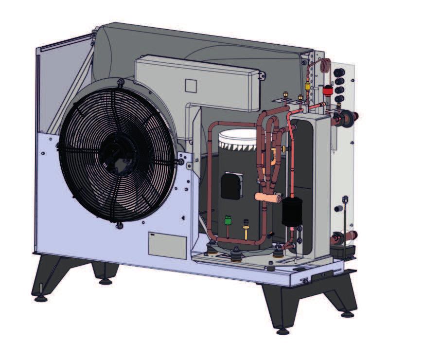
12 1.5 Component location


13 Compressor 2. 4-way valve 3. Condenser 4. Expansion valve 5. High pressure sensor 6. Low pressure sensor 7. High pressure switch 8. Connection box 9. Bleeding nipple/water 10. Drying fi lter 11. Suction gas sensor 12. Primary l ow sensor 13. Return sensor 14. Outdoor sensor 15. Hot gas sensor 16. Fan 17. Defrosting sensor in evaporator 18. Fan sensor 19. Power supply 20. Communication product 21. Communication, series connection 22. Power supply, circulation pump 23. Communication, circulation pump 24. Type plate with serial number etc. 25. Compressor heater 26. Evaporator 27. Packaged components (fi lter ball valve and condensate drain) in cardboard box under product on pallet. 13
14 2. Connection alternative 2.1 General The illustration below shows the different connection alternatives available for the In some cases, a CTC Converter or CTC Basic display may be needed. See the chapter on Connecting the control system. Alternative A The can be connected to the products below.! CTC EcoZenith i250 can be connected to products with an output up to 11 kw. CTC EcoLogic! Older products (version 3) must use the CTC Converter as an interpreter to control the. CTC EcoZenith CTC CTC EcoZenith i550pro i550 i550pro CTC EcoZenith i250 CTC EcoZenith i350 CTC EcoVent i350f 14
15 3. Important to remember! Check the following points in particular at the time of delivery and installation: 2.2 Transportation The product must be transported and stored in an upright position. Transport the unit to the installation site before removing the packaging. Remove the packaging and check before installation that the product has not been damaged in transit. Report any transport damage to the carrier. Handle the product with a forklift if possible, or lifting straps around the pallet, NOTE! Can only be used with the packaging on. 2.3 Positioning Place the product on a solid foundation. See chapter 'Placement of the heat pump'. Flexible hoses should be installed closest to the heat pump. Outdoor pipes should be thoroughly insulated with weather-proof insulation. Ensure that pipes used between the heat pump and the heating system are of adequate dimensions. Ensure that the circulation pump has sufficient capacity to pump the water to the heat pump. 2.4 Recycling The packaging must be deposited at a recycling station or with the installation engineer for correct waste management. At the end of the product s life cycle, it must be recycled in a correct way and be transported to a waste station or reseller offering a service of that type. Disposing of the product as household waste is not permitted. It is of great importance that the product's refrigerant, compressor oil and electrical/electronic equipment are properly disposed of. 2.5 After commissioning The installation engineer advises the property owner on the construction and servicing of the system. The installation engineer fills in a checklist and contact information the customer and installation engineer sign the list, which the customer keeps. 15


16 4. Installation This chapter is aimed at anyone responsible for one or more of the installations required to ensure that the product works the way the property owner wants. Take your time going through functions and settings with the property owner and answer any questions. Both you and the heat pump benefit from a user who has completely understood how the system operates and should be maintained. The installation must be carried out in accordance with current MCS standards. Refer to MIS 3005 and associated building regs Part L,F & G. The product must be connected to an expansion vessel in an open or closed system. Do not forget to flush the radiator system clean before connection. The heat pump operates with a primary flow/return temperature across the condenser of up to 65/58 C. Transportation Transport the unit to the installation site before removing the packaging. Handle the product in the following manner: kg Forklift Lifting band around the pallet. NB: Can only be used with the packaging on. axbxc Unpacking Unpack the heat pump when it is placed next to its installation site. Check that the product has not been damaged in transit. Report any transport damage to the carrier. Also check that the delivery is complete according to the list below. Delivery includes 1 x heat pump Packaged components (see chapter titled Component Location ) -filter ball valve: G1 (EcoAir ), G1¼ (EcoAir ) -condensate drain: G1¼ 15 m LiYCY (TP 2x2x0,75 mm2) cable with connector for communication, fitted. 2 m power cable, fitted: 16 EcoAir x400V 5G x 1,5 mm² EcoAir x400V 5G x 2,5 mm² EcoAir x230V 3G x 4 mm²! The product must be transported and stored in an upright position.
17 5. Placement of the heat pump Place the heat pump so that noise from the compressor and fan does not disturb the surroundings. No not place the heat pump right next to a bedroom window, patio or fence. is normally placed on an outside wall. There should be a space of at least 250 mm (EcoAir ) or 400 mm (EcoAir ) between the product and the wall so that outdoor air can pass freely in through the evaporator. If the heat pump is placed in a corner, there should be a space of at least 250 mm between the side of the heat pump and the wall. Allow a space of at least 2 metres between the heat pump and any bushes etc. Take the distance to the nearest neighbour into account by checking the noise data in the noise data chapter. The recommended distance between units is 400 mm. The legs of the CTC EcoAir must stand stably on concrete blocks or similar. Use a spirit level to adjust the unit, so that it is completely level. Due to the design of the stand and the weight of the pump, it is not necessary to secure the unit to the ground or the wall. Installing the heat pump in a sheltered spot is inadvisable, and so is placing it in an outhouse or car port, because the air should flow as freely as possible through the heat pump and used air should not to be sucked into the inlet on the back. This can cause abnormal ice formation in the evaporator. If the product is in an exposed location, with extra harsh weather conditions, then a suitable covering or sheltered location is justified.!these guidelines must be followed in order for your to give the best performance. 400 mm ( ). 250 mm ( ) Rec. 400 mm Min 2 m 17
18 6. Preparation and drainage The heat pump should be positioned so that the house cannot be damaged and the condensation water can easily drain into the ground. The foundation should be of concrete blocks or similar, resting on crushed stones or gravel. Make a 'stone curb' under the heat pump. Remember that there may be up to 70 litres of condensation water a day under some conditions, from the largest model. Make a cm deep hole. Place a moisture barrier in the hole on the side against the foundations of the building Half fill the hole with crushed stones and lay concrete blocks or similar. Mark up the c/c dimension (1155/1285 mm) between the blocks to match the span of the heat pump stand. *c/c distance CTC EcoAir CTC EcoAir length (depth) mm 1155 (451) 1285 (551) Use a spirit level to ensure that the blocks are level. Place crushed stones around the blocks to achieve optimal drainage Concrete blocks c/c distance 1155/1285 Concrete blocks Moisture barrier, up against the building foundations. Coarse crushed stone about cm deep. 451/551 mm Concrete blocks 18
19 6.1 Condensation water The condensation tray is built into the heat pump and is used to divert most of the condensation water. The tray can be connected to a suitable drain. Connection diameter: 42 mm. A heating cable (available as an accessory) should be placed in the pipe to prevent refreezing. The heating cable is connected to the electrical cabinet in the (to be performed by an authorised electrician and according to applicable provisions.) If the house has a cellar, it is advisable to route the condensation water to a floor drain indoors (to be performed according to the applicable rules). The pipe should be installed with a slope towards the house and above the ground (so no other water can get into the cellar). Wall apertures should be sealed and insulated A water trap must be connected to the inside to prevent air from circulating in the pipe. If there is a stone curb, the outlet from the condensation water pipe should be placed at a frost-free depth. The condensation water may also be routed into the house drains, e.g. from the downpipes. Here a heating cable must be placed in the pipes that are not frost-free. Water trap Frost-free depth 19
20 7. Pipe installation The installation must be carried out in accordance with current MCS standards. Refer to MIS 3005 and associated building regs Part L,F & G. The boiler must be connected to an expansion vessel in an open or closed system. Do not forget to flush the radiator system clean before connection. 7.1 Pipe connection Return lines of at least 22 mm (for ) and 28 mm (for ) copper pipe are connected to the heat pump. For longer pipes, the installer should calculate the pump and pipe dimensions needed to handle the minimum recommended flow for the concerned. Route the pipes between the heat pump and the boiler without any highest points. If this cannot be done, provide this highest point with an automatic air separator or and in line aerator. The connection to the heat pump should be made with a wirereinforced diffusion-tight hose for hot water, min. 1 diameter. Recommended hose length 1000 mm, to prevent noise from the heat pump spreading into the house and to take up any movement of the heat pump Pipes installed outside should be insulated with at least 13 mm thick insulation which is not sensitive to water. Ensure that the insulation is sealed tightly everywhere and that joints are thoroughly taped or glued. Indoor pipes should be insulated as far as the boiler with at least 9 mm thick insulation. This is to enable the heap pump to deliver the highest possible temperature to the boiler or tank without any losses. The product can be bled via the bleed valve inside the condenser.! Do not forget to flush the radiator system clean before connection.!note! Bleed only on this valve. The others are for the cooling system, If these are opened, refrigerant can leak! Pressure differential diagram for Pressure differential (kpa) EcoAir 406 EcoAir 408 EcoAir 410 EcoAir EcoAir ,1 0,2 0,3 0,4 0,5 0,6 0,7 Water low (l/s) 20

21 7.2 Example pipe connection EcoAir/EcoZenith i350 L The CTC EcoZenith i350 L has pipes at the rear right edge for connection of the heat pump. The heat pump s lower connection is connected to the right connection when viewed from the front, so that water is pumped out to the heat pump. The heat pump s upper connection is thus connected to the left connection. 1. Wire-reinforced diffusion-tight hose for hot water, min. 1. Hose length 1000 mm from the unit. 2. Outgoing (heated) water Ø28 mm connection on the condenser. 3. Incoming (cold) water Ø28 mm connection on the condenser. 4. Minimum Ø22 copper pipe. Insulated outside with 13 mm thick insulation. 5. Inside piping is insulted with 9 mm thick insulation. 6. Bleeder EcoAir/EcoZenith i350 H On the CTC EcoZenith i350 H, the heat pump is connected directly to the charge pump located under the tank. The heat pump s lower connection must be connected to the charge pump so that water is pumped out to the heat pump. The heat pump s upper connection is connected to the right diverting valve by the charge pump.!for optimum performance insulate outdoor and indoor piping as recommended in the instructions. 21
22 8. Circulation pump The choice of circulation pump depends on the type of system. Ensure that the circulation pump is large enough, so that there is sufficient flow through the heat pump. The circulation pump may be connected either internally within the or externally in the controlling unit. The charge pump supplies the with water. If the outdoor temperature is below + 2 C the charge pump runs constantly to eliminate any risk of freezing. Internal connection. With internal connection, the flow through the circulation pump is controlled by the controller in the. The control system for the CTC EcoAir 400 monitors and ensures that the unit is working within its operating range. For optimum performance, choose one of the A-class circulation pumps below. CTC EcoAir Yonos Para PWM 7,0 Item no CTC EcoAir 410 Yonos Para PWM 7,5 Item no CTC EcoAir UPM GEO Item no External connection With external connection, a circulation pump is installed so that the right flow through the heat pump can be guaranteed. Set the right temperature differential by adjusting the speed of the circulation pump. This is to ensure that the right differential for the current outdoor temperature is produced according to the table. Outdoor temp. ( C) CTC EcoAir 406 Primary flow 35 C Flow = 0.21 l/s 4 C 4,5 C 5,5 C 6,5 C 7 C 8 C CTC EcoAir 408 Primary flow 35 C Flow = 0,27 l/s 4 C 4,5 C 5,5 C 6,5 C 7 C 7,5 C CTC EcoAir 410 Primary flow 35 C Flow = 0.39 l/s 4 C 5 C 6 C 6.5 C 7 C 8 C CTC EcoAir 415 Primary flow 35 C Flow = 0.55 l/s 4 C 4.5 C 5.5 C 6.5 C 7 C 7.5 C CTC EcoAir 420 Primary flow 35 C Flow = 0.64 l/s 4 C 4.5 C 5.5 C 6.5 C 7 C 7.5 C In some systems with EcoLogic, the entire radiator flow must go through the heat pump, so the pump must be sized according to the flow of the whole system. For safe operation, the following flow must be maintained: CTC EcoAir 406: 760 l/tim CTC EcoAir 408: 960 l/tim CTC EcoAir 410: 1400 l/hr CTC EcoAir 415: 2000 l/hr CTC EcoAir 420: 2300 l/hr This provides about: 7 C temperature differential with an outside temperature of +7 C and a primary flow temperature of 35 C 22
23 8.1 Control/supply CTC EcoZenith i550 Pro The circulation pump is controlled and powered from the CTC EcoZenith i550pro. For more information, see the relevant product manual. CTC EcoZenith i250, CTC EcoZenith i350, CTC EcoVent i350f The circulation pump is factory-installed in the CTC EcoZenith i250. Control and supply take place from the product. For more information, see the relevant product manual. CTC EcoLogic PRO Up to 10 heat pumps can be connected to a CTC EcoLogic PRO. The circulation pumps in heat pumps 1 and 2 can then be connected to the CTC EcoLogic PRO. The circulation pumps for heat pumps 3-10 should be connected to the. CTC EcoLogic v3 The circulation pump (not speed-controlled) is controlled and powered from the. CTC EcoZenith v3 The circulation pump (not speed-controlled) is controlled and powered from the. CTC EcoEl v3 The circulation pump (not speed-controlled) is controlled and powered from the. 8.2 Operating range The control system for the monitors and ensures that the unit is working within its operating range. flow line temp outdoor temp 23
24 9. Electrical installation The installation and heat pump connection must be done by an authorised electrician. All wiring must be installed according to valid requirements. 9.1 Electrical installation 400V 3N~ Supply, black connector The must be connected to 400V 3N~ 50 Hz and protective earth. The minimum group fuse size is specified in 'Technical data'. The 2 m long power supply cable is pre-connected to the product. 9.2 Electrical installation 230V 1N~ Supply, black connector The must be connected to 230V 1N~ 50 Hz and protective earth. The minimum group fuse size is specified in 'Technical data'. The 2 m long power supply cable is pre-connected to the product. 9.3 Safety switch The installation should be preceded by a dual pole isolating safety switch which ensures disconnection from all electric power sources. 9.4 Alarm output The is fitted with a potential-free alarm output which is activated if any alarm is active in the heat pump. This output may be connected to a maximum load of 1 A 250 V AC. An external fuse should also be used. Cable approved for 230 V AC must be used for connecting this output, irrespective of the load that is connected. For connection information, see the wiring diagram. Detailed view from wiring diagram Termination one heat pump When installing 1 heat pump, dip-switch 2 should be set to the ON position. ON ON 1 2 ON
25 9.4.2 Termination for connection of heat pumps in series In a series connection dip switch 2 must be turned OFF on all heat pumps except the last one, which should be set to the ON position.. CTC EcoZenith i550 PRO/ CTC EcoLogic Pro/Family A1 A3 A2 ON ON ON OFF OFF ON! When connected in series, the last heat pump must be set to the terminated position. Read more under the chapter Electrical installation/ Terminated position Heatpump in series - address When connecting more than one heat pump to a CTC EcoLogic Pro or CTC EcoZenith 550 Pro, the CTC Basic Display accessory must be used to address the various heat pumps A1, A2, A3, etc. All units are factory-set addressed to A1. For connection, see the manual for the CTC Basic Display. Recommended cable between products LiYCY (TP). CTC Basic Display (accessory) Connection CTC Basic Display Connecting the CTC Basic Display (accessory) ON ON ON ON 1 2 To be able to control your heatpump with CTC Basic display make sure that dipswitch 1 is set to ON. see image. 25
; connect the shielding to the next heat pump here.")
26 Heat pumps connected in series The last heat pump in the series connection CTC Basic Display A1 A2 ON 1 ON 2 1 OFF 2 OFF A3 A4 ON ON ON OFF B A G Sc B A G Sc Green Shielding White Brown Shielding White Green Brown PE Connect each cable to the next heat pump in the series conne ction here. 26 Remove the loop(pe); connect the shielding to the next heat pump here. Make sure DIP switch 2 is in the ON position on the last heat pump in the series connection. The loop(pe) should be left in place.
27 10. Connecting the control system 10.1 General When connecting the to products with different control systems, accessories are sometimes needed to control the products. The various alternatives available are described in this section Connection alternative 1, one heatpump CTC EcoZenith i250, CTC EcoZenith i550 Pro, CTC EcoZenith i350, CTC EcoVent i350f When connecting a to a CTC EcoZenith i250, CTC EcoZenith i550 Pro, CTC EcoZenith i350, CTC EcoVent i350f and CTC EcoLogic Pro the communication cable (LiYCY (TP)) is connected directly to each product Connection alternative 2, heatpumps in series.! When connected in series, the last heat pump must be set to the terminated position. Read more under the chapter Electrical installation/ Terminated position CTC Ecologic Pro/Family eller CTC EcoZenith i550 Pro When connecting more than one heat pump to a CTC EcoLogic Family/Pro or CTC EcoZenith i550 Pro the CTC Basic Display accessory must be used to address the various heat pumps A1, A2, A3, etc. All units are factory-set addressed to A1. For connection, see the manual for the CTC Basic Display. Recommended cable between products LiYCY (TP). CTC EcoLogic Pro CTC Basic Display 27
28 ON RS485 TX RS485 RX COM TX COM RX 10.4 Connection alternative 3 CTC EcoEl v3 Because these products have an older control system of v3 type, the CTC Converter accessory must be used as an interpreter to control the CTC EcoAir 400. See the manual for the CTC Converter for connecting this.!version 3 (V3) relates to models manufactured from 2006 onwards. CTC EcoEl V3 CTC E V CTC Converter 28
29 ON RS485 TX RS485 RX COM TX COM RX 10.5 Connection alternative 4 CTC EcoZenith v3 or CTC EcoLogic v3 Because these products have an older control system of v3 type, the CTC Converter accessory must be used as an interpreter to control the CTC EcoAir 400. See the manual for the CTC Converter for connecting this.!version 3 (V3) relates to models manufactured from 2006 onwards. The CTC EcoZenith version 3 is available in two different variants. An earlier variant with only one communication port, and a later one with three such ports. The earlier one will have a serial number starting from: Prod. no. Item no. Model CTC EcoZenith I 550 3x400V CTC EcoZenith I 550 3x230V CTC EcoZenith I 550 BBR CTC EcoZenith I 550 1x230V The earlier version needs a Converter to control the heat pump. CTC EcoZenith V3 CTC EcoLogic V3! If new (version 4) and old (version 3) heat pumps are combined in an installation, the new one must be addressed A1. CTC Converter CTC EcoAir V3!When connected in series, the last CTC EcoAir 400 must be set to the terminated position. 29
30 ON RS485 TX RS485 RX COM TX COM RX ON RS485 TX RS485 RX COM TX COM RX ON RS485 TX RS485 RX COM TX COM RX 10.6 Connection alternative 5 CTC EcoZenith I 550 The CTC EcoZenith version 3 is available in two different variants. An earlier variant with only one communication port, and a later one with three such ports. The later one will have a serial number starting from: Prod. no. Item no. Model CTC EcoZenith I 550 3x400V CTC EcoZenith I 550 3x230V CTC EcoZenith I 550 BBR CTC EcoZenith I 550 1x230V For the later variant a CTC Converter is needed for each version 4 heat pump. See the manual for the CTC Converter for connection. CTC EcoZenith V3 CTC Converter CTC Converter CTC Converter 30
31 10.7 Parts list A2 Relay/main PCB A4 PCB white softstarter, motorprotection and contactorfunction B1 Primary flow sensor Type 2 NTC/NTC 22 B7 Return sensor Type 2 NTC/NTC 22 B15 Outdoor sensor Type 1 NTC/NTC 22 B16 Defrost sensor Type 1 NTC/NTC 22 B20 Fan sensor Type 1 NTC/NTC 22 B21 Hotgas sensor Type 3 NTC/NTC 50 B22 Suctiongas sensor Type 1 NTC/NTC 015 B100 Highpressure sensor B101 Lowpressure sensor C1 Capacitor compressor (1-phase) C2 Capacitor E10 Compressor heater E11 Vaporizer heater E12 Heating cable (option) F1 Fuse (option) F20 Highpressure switch G11 Loadpump (option) K1 Contactor (EA ) M1 Compressor M10 Fan X1 Terminal XM1 Connector supply Male XM2 Connector supply Female XC1 Connector communication Male XC2 Connector communication Female Y10 Expansion valve Y11 Solenoid valve 31
32 10.8 Wiring diagram 400 V 3N~ Communication (Grey connector) Supply (Black connector) 32
33 Ω Ω Ω Ω Ω Ω Ω Ω Ω 33
34 10.9 Wiring diagram 230V 1N~ Communication (Grey connector) Supply (Black connector) 34
35 35
36 11. First start 1. Check that the boiler and system are full of water and have been bled. 2. Check that all connections are tight. 3. Check that sensors and the charge pump are connected to the power source. 4. Energise the heat pump by switching on the safety switch (the main switch). Once the system has heated up, check that all connections are tight, the various systems have been bled, heat is coming out into the system and warm water is coming out at the tap locations. 12. Noise data Standard Model EcoAir 406 Noise level 56 db(a) Noise pressure 5 m* db(a) Noise pressure 10 m* db(a) EcoAir db(a) db(a) db(a) EcoAir db(a) db(a) db(a) EcoAir db(a) db(a) db(a) EcoAir db(a) db(a) db(a) Silent mode Model Noise level Noise pressure 5 m* Noise pressure 10 m* EcoAir db(a) db(a) db(a) EcoAir db(a) db(a) db(a) * The given noise pressure should be taken as an indication as the level is affected by the surroundings. The upper value corresponds to 100% reflecting ground and walls (smooth concrete).values according to EN Silent mode The CTC EcoAir 415 and 420 can be set to 'silent mode' by their respective control systems. In this position, the fan runs at a lower speed which means that the product makes less noise. The stated output will then be reduced by a few percent, depending on the operating situation. 36
37 Temperature C Sensor Type 1 NTC kω Temperature C Sensor Type 2 NTC kω Temperature C Sensor Type 3 NTC kω Temperature C NTC 50 kω Sensor data 37
38 Temperature C NTC 22 k Resistance Ω Temperature C NTC 015 Resistance Ω
39 13. Operation and Maintenance When the installer has installed your new heat pump, you should check together that the system is in perfect operating condition. Let the installer show you where the power switches, controls and fuses are so that you know how the system works and how it should be maintained. Bleed the radiators (depending on type of system) after around three days of operation and top up with water if required Defrosting The is fitted with hot gas defrosting. The heat pump checks constantly whether defrosting is needed and, if so, defrosting starts, the fan stops, the four-way valve changes direction and the hot gas goes to the evaporator instead. A hissing sound is heard as the water drains from the evaporator. When the product has defrosted, the fan starts and the hot gas goes into the condenser instead, and the heat pump returns to normal operation The fan The fan starts 15 seconds before the condenser and runs until the compressor stops. During defrosting the fan stops and restarts when defrosting is finished Maintenance A large amount of water passes through the evaporator in the CTC EcoAir 400. Leaves and other debris can get stuck and restrict the air flow. At least once year the evaporator coil should be checked and cleared of particles that block the air flow. The evaporator and outer covering should be cleaned with a damp cloth or soft brush. No other periodic maintenance or inspection is necessary Periodic maintenance After three weeks operation and then every three months during the first year. Then once a year: Check that the installation is free of leaks. Check that the product and system are free of air; bleed if needed. Check that the evaporator is clean. No annual leakage control of the refrigerant is required 13.5 Shut-down The heat pump is shut down using the operating switch. If there is a risk of the water freezing, ensure that there is circulation through the heat pump or drain out all the water from the Condensation water tray The condensation tray collects water formed on the CTC EcoAir evaporator during operation and defrosting. The condensation tray is equipped with an electric heating coil which keeps the tray free of ice when it is freezing outside. The condensation tray is located at the bottom on the back of CTC EcoAir 400. By lifting the handle and pulling it out, you can clean and inspect the condensation tray. You can buy a heating cable as an accessory and connect it to the EcoAir 400. The cable is installed in the drain pipe from the condensation tray to a frost-free drain. 39
40 14. Troubleshooting/measures The is designed to provide reliable operation and high levels of comfort, and to have a long service life. Various tips are given below which may be helpful and guide you in the event of an operational malfunction. If a fault occurs, you should always contact the installer who installed your unit. If the installer believes the malfunction is due to a material or design fault, then they will contact CTC-UK to check and rectify the issue. Always provide the product s serial number Air problems If you hear a rasping sound from the heat pump, check that it is properly bled. Top up with water where required, so that the correct pressure is achieved. If this noise recurs, call a technician to check the cause Alarms Any alarms and information texts from the are displayed in the product which is used to control it; you should therefore consult the manual for that product Circulation and Defrosting If the circulation between the indoor and the outdoor unit is reduced or stops, the high pressure switch is triggered. Possible reasons for this: Defective circulating pump/circulating pump too small Air in the pipes Condenser clogged Other intermediate obstructions to the water flow During defrosting the fan stops but the compressor operates and the melted snow and ice flows into the condensation tray under the heat pump. When defrosting stops, the fan starts again and initially a vapour cloud, consisting of damp air which condenses in the cold outdoor air, is created. This is perfectly normal and stops after a few seconds. If the pump heats poorly, check that no unusual ice formation has occurred. Possible reasons for this: Defective defrosting automation Lack of refrigerant (leakage) Extreme weather conditions. Remember that is an air source heat pump which gives less heat power when outdoor temperatures fall, while the heating needs of the house increase. When temperatures fall quickly, this means that you may experience a lack of heating power. 40
41
42
43
44 Enertech AB. P.O Box 309 SE Ljungby Sweden
CTC EcoAir 510M. Installation- and Maintenance Manual. Modulating air/water heat pump 230 V 1N~ Providing sustainable energy solutions worldwide
 162 205 72-3 2019-01-10 Providing sustainable energy solutions worldwide Installation- and Maintenance Manual CTC EcoAir 510M Modulating air/water heat pump 230 V 1N~ IMPORTANT READ CAREFULLY BEFORE USE
Installation- and Maintenance Manual CTC EcoAir 500M. Modulating air/water heat pump. Providing sustainable energy solutions worldwide
 162 105 54-1 2015-08-21 Providing sustainable energy solutions worldwide Installation- and Maintenance Manual CTC EcoAir 500M Modulating air/water heat pump Installation and Maintenance Manual CTC EcoAir
Installation and Maintenance Manual CTC EcoAir. Model 406 I 408 I 410 I 415 I 420 Air source heat pump
 162 105 27-4 2015-09-14 Providing sustainable energy solutions worldwide Installation and Maintenance Manual CTC EcoAir Model 406 I 408 I 410 I 415 I 420 Air source heat pump Installation and Maintenance
Installation- and Maintenance Manual CTC EcoAir 520M. Modulating air/water heat pump. Providing sustainable energy solutions worldwide
 162 105 43-1 2015-06-18 Providing sustainable energy solutions worldwide Installation- and Maintenance Manual Modulating air/water heat pump Installation and Maintenance Manual Modulating air/water heat
Installation- and Maintenance Manual CTC EcoAir 510M. Modulating air/water heat pump 400V 3N~ Providing sustainable energy solutions worldwide
 162 105 63-1 Providing sustainable energy solutions worldwide Installation- and Maintenance Manual CTC EcoAir 510M Modulating air/water heat pump 400V 3N~ IMPORTANT READ CAREFULLY BEFORE USE KEEP FOR FUTURE
Installation and Maintenance Manual CTC EcoPart 400. Model V 3N~ / 230V 1N~ Providing sustainable energy solutions worldwide
 162 105 51-2 2015-09-15 Providing sustainable energy solutions worldwide Installation and Maintenance Manual Model 406-417 400V 3N~ / 230V 1N~ Removing the cooling module 1. Disconnect the cooling module
Installation and Maintenance Manual CTC EcoPart 400. Model V 3N~ / 230V 1N~ Providing sustainable energy solutions worldwide
 162 105 32-2 2014-05 12 Providing sustainable energy solutions worldwide Installation and Maintenance Manual Model 406-417 400V 3N~ / 230V 1N~ Removing the cooling module 1. Disconnect the cooling module
/ Installation and Maintenance Manua. CTC EcoAir. Model 105 I 107 I 110 Polar Edition 107 I 110. Air/Water Heat Pump
 161 505 87/1 2010-12 29 Installation and Maintenance Manua CTC EcoAir Model 105 I 107 I 110 Polar Edition 107 I 110 Air/Water Heat Pump Installation and Maintenance Manual CTC EcoAir 105 I 107 I 110 CTC
Providing sustainable energy solutions worldwide. Installation and Maintenance Manual. CTC EcoPart XL.
 162 105 18-3 2014-11-26 Providing sustainable energy solutions worldwide Installation and Maintenance Manual Model 424-434 Removing the cooling module 1. Disconnect the cooling module s power cable connector
CTC EcoPart 400. Installation and Maintenance Manual. Model V 3N~ / 230V 1N~ Providing sustainable energy solutions worldwide
 162 205 01-1 2017-05-30 Providing sustainable energy solutions worldwide Installation and Maintenance Manual Model 406-417 400V 3N~ / 230V 1N~ IMPORTANT READ CAREFULLY BEFORE USE KEEP FOR FUTURE REFERENCE
Installation and Maintenance Manual CTC EcoPart i425-i435 Pro CTC EcoPart
 162 105 52-1 2015-05-21 Providing sustainable energy solutions worldwide Installation and Maintenance Manual CTC EcoPart i425-i435 Pro CTC EcoPart 425-435 Removing the cooling module 1. Disconnect the
Installation and Maintenance Manual CTC EcoPart i425-i435 Pro CTC EcoPart
 162 105 38-1 2014-08-14 Providing sustainable energy solutions worldwide Installation and Maintenance Manual CTC EcoPart i425-i435 Pro CTC EcoPart 425-435 Removing the cooling module 1. Disconnect the
CTC EcoComfort. Installation and Maintenance Manual. for the property owner. Providing sustainable energy solutions worldwide
 162 105 25-2 2015-11-16 Providing sustainable energy solutions worldwide Installation and Maintenance Manual CTC EcoComfort for the property owner IMPORTANT READ CAREFULLY BEFORE USE KEEP FOR FUTURE REFERENCE
Installation instructions Danfoss heat pump DHP-R
 Installation instructions Danfoss heat pump DHP-R Table of contents DHP-R 1 Important information........................................................... 5 1.1 Refrigerant...5 1.2 Noise and vibrations...5
Installer manual AG-AA10. Air/air heat pump IHB GB AG-AA10-30 AG-AA10-40/50
 -30 Installer manual Air/air heat pump -40/50 IHB GB 1516-1 331554 Table of Contents 1 Important information 2 5 Installation 7 Safety information 2 Model combinations 7 Read before starting the installation
Planning guide. Atec.
 www.thermia.com Thermia Värmepumpar is not liable or bound by warranty if these instructions are not adhered to during installation or service. The English language is used for the original instructions.
AUTOMATIC MODULAR ICE FLAKER
 AUTOMATIC MODULAR ICE FLAKER INSTRUCTIONS AND WARNINGS 24479 rev. 08 It is strictly forbidden to reproduce this instruction manual or any part thereof. 1 5 3 4 Mod. N. V. W 2 2 M8 18 8 18 M8 M8 3 ~ 200
HT V2 HT Split
 Scroll compressor Refrigerant R07C Aqu@Scop HT V Aqu@Scop HT Split High Temperature Air-to-Water Heat Pumps Models -, -7 and 8-9.0 to 7.9kW Aqu@Scop HT V / Aqu@Scop HT Split Installation examples - Single
PHRIE / PHIE InvERTER monoblock air To water HEaT PumP medium TEmPERaTuRE
 TEcHnIcal InsTRucTIons PHRIE / PHIE InvERTER monoblock air To water HEaT PumP medium TEmPERaTuRE PHRIE 095 PHRIE 1 PHIE 095 PHIE 1 PHRIE 155 PHRIE 157 PHRIE 175 PHRIE 177 PHRIE 195 PHRIE 197 PHRIE 7 PHRIE
MODULAR AUTOMATIC GRANULAR ICE FLAKER
 MODULAR AUTOMATIC GRANULAR ICE FLAKER INSTRUCTIONS AND WARNINGS 24479 rev. 03 It is strictly forbidden to reproduce this instruction manual or any part thereof. Dear Customer, Congratulations on having
AUTOMATIC ICE-CUBE MAKER - INSTRUCTIONS AND WARNINGS
 AUTOMATIC ICE-CUBE MAKER - INSTRUCTIONS AND WARNINGS Dear Customer, Congratulations on having chosen a quality product which will certainly fully meet your expectations. Thank you for having purchased
End customer overview
 16210568-1 2016-08-23 End customer overview Indoor module with heat pump control 1. Sign the installation checklist. 2. Serial no. behind touchscreen. 3. Bleed radiator system and products, approx. one
AUTOMATIC MODULAR ICE-CUBE MAKER
 AUTOMATIC MODULAR ICE-CUBE MAKER INSTRUCTIONS AND WARNINGS 24851 ed. 06-2012 It is strictly forbidden to reproduce this instruction manual or any part thereof. Dear Customer, Congratulations on having
NIBE F2120 Air/water heat pump
 NIBE Air/water heat pump A breakthrough in efficiency NIBE is an air/water heat pump that has made a real breakthrough with a market leading SCOP. utilises the heat from the outdoor air which places big
CTC GSi 12. Installation and Maintenance Manual. Modulating ground source heat pump 230V 1N~/230V 3~ Providing sustainable energy solutions worldwide
 162 305 04-3 Providing sustainable energy solutions worldwide Installation and Maintenance Manual CTC GSi 12 Modulating ground source heat pump 230V 1N~/230V 3~ IMPORTANT READ CAREFULLY BEFORE USE KEEP
NIBE F2026 air/water heat pump. fresh air s free. NIBE F2026. Efficient scroll compressor that operates at temperatures down to -20 C.
 NIBE F2026 air/water heat pump fresh air s free. Efficient scroll compressor that operates at temperatures down to -20 C. Automatic 2-step capacity regulator for the fan (not 6kW). Manufactured in three
AUTOMATIC GRANULAR ICE FLAKER
 AUTOMATIC GRANULAR ICE FLAKER INSTRUCTIONS AND WARNINGS 24480 rev. 01 It is strictly forbidden to reproduce this instruction manual or any part thereof. Dear Customer, Congratulations on choosing a
Swedish design and manufacture since 1967
 Swedish design and manufacture since 167 PVP MA20-14 rev.2 Manual User manual Copyright 2017 Pahlén AB, Box 728, SE-14 27 Upplands Väsby, Sweden Tel. +46 8 54 110 50, Fax +46 8 50 868 80, e-mail: info@pahlen.se,
CTC GSi 12. Installation and Maintenance Manual. Modulating ground source heat pump 400V 3N~ Providing sustainable energy solutions worldwide
 162 105 78-1 2017-02-13 Providing sustainable energy solutions worldwide Installation and Maintenance Manual CTC GSi 12 Modulating ground source heat pump 400V 3N~ IMPORTANT READ CAREFULLY BEFORE USE KEEP
CHGV AIR COOLED WATER CHILLER WITH HYDRAULIC EQUIPMENT AIR / WATER 47 to 78 kw
 TECHNICAL INSTRUCTIONS CHGV AIR COOLED WATER CHILLER WITH HYDRAULIC EQUIPMENT AIR / WATER 47 to 78 kw CHGV 50 CHGV 64 CHGV 72 CHGV 80 PHRV heat pump model also available November 2007 10 12 167 - GB -
CHGV AIR COOLED WATER CHILLER WITH HYDRAULIC EQUIPMENT AIR / WATER 21 to 39 kw
 TECHNICAL INSTRUCTIONS CHGV AIR COOLED WATER CHILLER WITH HYDRAULIC EQUIPMENT AIR / WATER 21 to 39 kw CHGV 22 CHGV 2 CHGV 32 CHGV 40 PHRV heat pump model also available September 2007 10 12 11 - GB - 02
Technical description. Atec.
 www.thermia.com Thermia Värmepumpar is not liable or bound by warranty if these instructions are not adhered to during installation or service. The English language is used for the original instructions.
Double Door - Dual Zone Wine Cooler
 THE PERFECT BALANCE OF FUNCTION, STYLE AND RELIABILITY LAUNDRY - DISHWASHING - COOKING - COOLING Installation and Operating Manual Double Door - Dual Zone Wine Cooler WS38SDDX Stainless Steel Please read
AUTOMATIC MODULAR ICE-CUBE MAKER WITH VERTICAL EVAPORATOR SYSTEM
 AUTOMATIC MODULAR ICE-CUBE MAKER WITH VERTICAL EVAPORATOR SYSTEM INSTRUCTIONS AND WARNINGS 24481 ed. 11-2007 It is strictly forbidden to reproduce this instruction manual or any part thereof. Dear
EH0533 Indoor Climate Control
 EH0533 Indoor Climate Control 2.8 kw of cooling, 2.9 kw of heating Air Conditioning Efficient heating (air-source heat-pump) Cooling Remote control Suitable for low-wall installation No external unit required
Electronically controlled instantaneous water heater. MCX: 27300, and models. Installation instructions
 Electronically controlled instantaneous water heater MCX: 27300, 27400 and 27600 models Installation instructions These appliances deliver water not exceeding 50 ºC in accordance with AS3498. 1. Overview
Providing sustainable energy solutions worldwide. Installation and Maintenance Manual CTC EcoHeat V 3N~ / 230V 1N~
 162 105 30-2 2013-09-23 Providing sustainable energy solutions worldwide Installation and Maintenance Manual CTC EcoHeat 400 400V 3N~ / 230V 1N~ Removing the cooling module 1. Disconnect the cooling module
EH0554 Indoor Climate Control
 EH0554 Indoor Climate Control 3.2kW heating or cooling capacity Air conditioning Dehumidification Cooling Efficient heating via air-source heat-pump Suitable for high- or low-wall installation No external
CTC EcoZenith i350 L/H Indoor module with heat pump control available in two heights
 CTC EcoZenith i30 L/H Indoor module with heat pump control available in two heights Ultra-efficient indoor module available in two heights with many options and built-in heat pump control. CTC EcoZenith
Local air conditioner
 Instruction Manual Local air conditioner LAC08C16 Contents Safety Warnings...4 Unpacking...7 Product Overview...8 Front View...8 Rear View...8 Control Panel...9 Remote Control... 10 Moving the Unit...10
PRODUCT DATA COMFORT 450 BY NILAN. Ventilation & passive heat recovery. Passive heat recovery. < 450 m 3 /h
 PRODUCT DATA COMFORT 40 BY NILAN Ventilation & passive heat recovery Domestic Passive heat recovery Ventilation < 40 m /h COMFORT 40 Product description The Comfort 40 is an energy-efficient ventilation
CTC EcoZenith i350 Indoor module with heat pump control available in two heights
 CTC EcoZenith i30 Indoor module with heat pump control available in two heights Ultra-efficient indoor module available in two heights with many options and built-in heat pump control. CTC EcoZenith i30
Warning: 230V / 1ph / 50Hz V / 3ph / 50Hz. Remarks: Make sure that you have enough power. (See page 15 Cable table)
") 1 2 Warning: - Do not place your hand or any other objects into the air outlet and fan. It could damage the heat pump and cause injuries; - In case of any abnormality with the heat pump, cut off the power
1 2 Warning: - Do not place your hand or any other objects into the air outlet and fan. It could damage the heat pump and cause injuries; - In case of any abnormality with the heat pump, cut off the power
Drying Cabinet Installation and Operating Manual
 Drying Cabinet Installation and Operating Manual Model:- ECO Dryer 2.0 HP Heat Pump Technology CONTENTS THIS USER MANUAL 3 DATA PLATE DETAILS 3 ADVICE ON SAFE OPERATION 3 DESCRIPTION OF THE CABINET 4 AIR
COMPACT PORTABLE AIR CONDITIONER USER MANUAL
 COMPACT PORTABLE AIR CONDITIONER USER MANUAL Thank you for choosing ElectriQ Please read this user manual before using this innovative Air Conditioner and keep it safe for future reference. Visit our page
PC20-AMFII / PC40-AMF USER MANUAL
 VERY IMPORTANT PC20-AMFII / PC40-AMF USER MANUAL Please read this instruction guide before install and using your portable air conditioner unit. This instruction manual is the universal-purpose version
CD30 / CD30E DEHUMIDIFIER (FULL PRODUCT RANGE) OWNER S MANUAL
 OWNER S MANUAL") CD30 / CD30E DEHUMIDIFIER (FULL PRODUCT RANGE) OWNER S MANUAL www.eipl.co.uk Page 1 of 16 UNPACKING Carefully remove the CD30 dehumidifier unit from its transit box and visually check for signs of transit
CD30 / CD30E DEHUMIDIFIER (FULL PRODUCT RANGE) OWNER S MANUAL www.eipl.co.uk Page 1 of 16 UNPACKING Carefully remove the CD30 dehumidifier unit from its transit box and visually check for signs of transit
NIBE SPLIT ACVM 270 Air/water heat pump
 NIBE SPLIT ACVM 270 Air/water heat pump NIBE SPLIT ACVM 270 system with complete indoor module NIBE SPLIT ACVM 270 is a complete modern heat pump system that offers effective technical energy saving and
Autofill Wall Mount Boilers
 USER INSTRUCTION MANUAL Autofill Wall Mount Boilers HELPLINE 0844 372 7766 Redring Warranty 2 Year Parts 2 Year Labour 083329501-05/12/13 Contents 1.0 About your Product My Product (please complete this
Installer manual AG-WL10
 LEK LED CLEAN TIMER OPERATION Installer manual Indoor unit air/air heat pump IHB GB 1637-1 331827 Table of Contents 1 Important information Safety information Read before starting the installation Electrical
User manual: Stainless steel CGN range Storage Refrigerators and FGN Storage Freezers
 User manual: Stainless steel CGN range Storage Refrigerators and FGN Storage Freezers To ensure safe operation, please read this user manual thoroughly before use. 2017 Husky. Husky reserve the right to
50L/D DEHUMIDIFIER. Model Number: IG9805 INSTRUCTIONS FOR USE
 50L/D DEHUMIDIFIER Model Number: IG9805 INSTRUCTIONS FOR USE Thank you for purchasing this product. Please read these instructions carefully before use. SAFETY INSTRUCTIONS IMPORTANT: This appliance is
AUTOMATIC ICE-CUBE MAKER
 AUTOMATIC ICE-CUBE MAKER INSTRUCTIONS AND WARNINGS 24478 ed. 11-2007 It is strictly forbidden to reproduce this instruction manual or any part thereof. Dear Customer, Congratulations on having chosen
CTC EcoZenith C 530 l 510
 Installation and Maintenance Manual CTC EcoZenith C 530 l 510 161 505 77/1 2010-02-18 Table of Contents For the property owner Welcome... 3 Important to remember!... 4 Safety Instructions... 4 Hot water...
The Classeq under counter range
 Installation & Operators Manual The under counter range Part number 902.0011 Revision C Effective date January 2010 Language English Glasswashers Eco 1 Eco 2 Eco 3 Duo 2 Duo 3 Dishwasher Hydro 500 Hydro
USER MANUAL SILENT16 PORTABLE AIR CONDITIONER
 USER MANUAL SILENT16 PORTABLE AIR CONDITIONER Thank you for choosing electriq Please read this user manual before using this innovative Air Conditioner and keep it safe for future reference. Visit our
OWNER S MANUAL. Vintage Signature Series models: AC750, AC1050, AC1100, AC1250, AC1500, AC1750. Proudly Made in the USA.
 OWNER S MANUAL Vintage Signature Series models: AC750, AC1050, AC1100, AC1250, AC1500, AC1750 Proudly Made in the USA support@aquacomfort.com 888-475-7443 Manufacturing High Quality, High Efficiency Heat
OPERATING INSTRUCTIONS
 EN DEHUMIDIFIER OPERATING INSTRUCTIONS Read the instructions carefully before operating or servicing the dehumidifier. Observe all the safety instructions; failure to observe the instructions may lead
PHRT HEAT PUMP WITH HYDRAULIC EQUIPMENT AIR / WATER 9 to 18 KW
 TECHNICAL INSTRUCTIONS PHRT HEAT PUMP WITH HYDRAULIC EQUIPMENT AIR / WATER to KW PHRT PHRT PHRT PHRT For terminal units and boiler overhaul applications Heating Cooling PHRT.00 kw -. kw PHRT.0 kw /.0 kw
CTC EcoMiniEl. Installation- and Maintenance Manual. External electric boiler. Providing sustainable energy solutions worldwide
 161 505 34-3 2015-09-18 Providing sustainable energy solutions worldwide Installation- and Maintenance Manual External electric boiler 161 505 34-3 2015-09-18 Installation- and Maintenance Manual External
Electronically controlled instantaneous water heater. MCX: 27300, and models. Instructions for the user
 Electronically controlled instantaneous water heater MCX: 27300, 27400 and 27600 models Instructions for the user These appliances deliver water not exceeding 50 ºC in accordance with AS3498. 1. Overview
Efficient heating that won t cost the earth
 Product Range Guide Efficient heating that won t cost the earth CTC is an international manufacturer of innovative renewable heating solutions. For over 90 years our ranges of high performance products
Electronically controlled instantaneous water heater. CEX 9-U: C models. Installation instructions
 Electronically controlled instantaneous water heater CEX 9-U: 27910-50 C models Installation instructions For 50 ºC models, the appliance delivers water not exceeding 50 ºC in accordance with AS3498. 1.
AQUARIUS 45 MARINE SERVICE MANUAL
 AQUARIUS 45 MARINE SERVICE MANUAL CONTENTS: PAGE 1. INTRODUCTION 3 2. SAFETY INSTRUCTIONS 4 3. BASIC INSTRUCTIONS 5 3.1. Installation Details 5 3.2. Operating the Boiler for the First Time 6 3.3. Troubleshooting
CHGV AIR COOLED WATER CHILLER WITH HYDRAULIC EQUIPMENT AIR / WATER 47 to 78 kw
 TECHNICAL INSTRUCTIONS CHGV AIR COOLED WATER CHILLER WITH HYDRAULIC EQUIPMENT AIR / WATER 47 to 78 kw CHGV CHGV 64 CHGV 72 CHGV 80 PHRV heat pump model also available May 2006 10 12 167 - GB - 00 MARKING
INSTALLATION AND USER MANUAL
 INSTALLATION AND USER MANUAL Thank you for choosing our product and trusting our company. This manual is to provide you with necessary information for optimal use and maintenance, please read carefully
OPERATING INSTRUCTIONS
 EN DEHUMIDIFIER LILIUM 11 LILIUM 13 OPERATING INSTRUCTIONS Read the instructions carefully before operating or servicing the dehumidifier. Observe all the safety instructions; failure to observe the instructions
AGEO CALEO. Water-to-water high temperature heat pumps USE RANGE DESCRIPTION. Designed to replace a conventional boiler and produce domestic hot water
 Designed to replace a conventional boiler and produce domestic hot water Heating capacity : 16 to 25 Heating Hydraulic module ENVIRONMENTALLY HFC R4A PROTECTION DE FRIENDLY L'ENVIRONNEMENT USE CIAT is
Installation manual W365H, W375H, W3105H, W3130H, W3180H, W3240H, W3300H Exacta & Clarus Control
 manual W365H, W375H, W305H, W330H, W380H, W3240H, W3300H Exacta & Clarus Control 438 9200-0 06.34 Contents 3 Contents Technical data... :... 2: Transportation and unpacking... 2: Siting and floor... 3:
INSTALLATION AND USER MANUAL
 INSTALLATION AND USER MANUAL t Thank you for choosing Aqua inverter heat pump. This manual provides you necessary information for optimal use and maintenance, please read it carefully and keep it for subsequent
MOBILE AIR CONDITIONER. User Manual PC15/20/26-BCB
 MOBILE AIR CONDITIONER User Manual PC15/20/26-BCB VERY IMPORTANT Please read this instruction guide before install and using your mini portable type air conditioner unit. This instruction manual is the
RM85 INDUSTRIAL DEHUMIDIFIER OWNER S MANUAL
 RM85 INDUSTRIAL DEHUMIDIFIER OWNER S MANUAL www.eipl.co.uk Page 1 of 12 INTRODUCTION Designed for a wide range of applications, the RM85 is a rugged, industrial unit, which utilizes an energy-efficient
PRODUCT DATA COMFORT 600 BY NILAN. Ventilation & passive heat recovery. Passive heat recovery. < 800 m 3 /h
 PRODUCT DATA COMFORT 00 BY NILAN Ventilation & passive heat recovery Domestic Passive heat recovery Ventilation < 800 m /h COMFORT 00 Product description The Comfort 00 is an energy-efficient ventilation
ECO85 INDUSTRIAL DEHUMIDIFIER OWNER S MANUAL
 ECO85 INDUSTRIAL DEHUMIDIFIER OWNER S MANUAL www.eipl.co.uk Page 1 of 12 INTRODUCTION Designed for a wide range of applications, the ECO85 dehumidifier is a rugged, industrial unit which utilizes an energy-efficient
CTC EcoZenith i250 Indoor module with heat pump control available in two heights
 CTC EcoZenith i50 Indoor module with heat pump control available in two heights The flexible indoor module with touchscreen and EnergyFlex. An efficient indoor module available in two heights with ample
USER MANUAL SILENT12 PORTABLE AIR CONDITIONER
 USER MANUAL SILENT12 PORTABLE AIR CONDITIONER Thank you for choosing electriq Please read this user manual before using this innovative Air Conditioner and keep it safe for future reference. Visit our
USER MANUAL TPS-M5/M55/M555
 VERY IMPORTANT Please read this instruction guide before install and using your mini portable type air conditioner unit. This instruction manual is the universal-purpose version for the units that you
FREE STAR INDUSTRIAL DEHUMIDIFIER USERS MANUAL
 FREE STAR INDUSTRIAL DEHUMIDIFIER USERS MANUAL www.ebacusa.com Page 1 of 13 UNPACKING Thank you for deciding to purchase an Ebac dehumidifier. Like the many tens of thousands of people who have already
LK Electric Boiler - 4,5
 LK Electric Boiler -, Design LK Electric Boiler, kw is a wall-mounted electric boiler, intended primarily for low-temperature heating systems, e.g. under floor heating. LK Electric Boiler, kw is delivered
Installation and Maintenance Manual CTC EcoHeat V 3N~ / 230V 1N~ Providing sustainable energy solutions worldwide
 162 105 46-7 Providing sustainable energy solutions worldwide Installation and Maintenance Manual CTC EcoHeat 400 400V 3N~ / 230V 1N~ IMPORTANT READ CAREFULLY BEFORE USE KEEP FOR FUTURE REFERENCE 2016-06-28
TTV 1500 / TTV 3000 OPERATING MANUAL CONVEYING FAN TRT-BA-TTV TC EN
 TTV 1500 / TTV 3000 EN OPERATING MANUAL CONVEYING FAN TRT-BA-TTV1500-3000-TC2016-26-004-EN Table of contents Notes regarding the operating manual... 2 You can download the current version of the operating
CHEST FREEZER HS225523
 CHEST FREEZER HS225523 WARNING! In order to ensure a normal operation of your refrigerating appliance, which uses a completely environmentally friendly refrigerant the R600a (flammable only under certain
F17W44_MFB_F_EN INSTALLATION INSTRUCTIONS
 F17W44_MFB_F_EN INSTALLATION INSTRUCTIONS Contents Page User instructions 3-5 General 3 Fan installation 3-4 Maintenance 3 Electrical installation 5 Troubleshooting 5 Technical description 6-8 General
10L Dehumidifier. Model Number: LDH V AC 50/60Hz 290W
 10L Dehumidifier Model Number: LDH1001 220-240V AC 50/60Hz 290W For Customer Services & Spare Parts please call 0345 209 7461 Opening times: Monday - Friday 8am 8pm & Saturday 9am 1pm Or visit us at www.productcare.co.uk
air conditioner/dehumidifier 9000btu/hr
 instructions for air conditioner/dehumidifier 9000btu/hr model no: SAC9001 Thank you for purchasing a Sealey product. Manufactured to a high standard, this product will, if used according to these instructions,
RM85 INDUSTRIAL DEHUMIDIFIER OWNER S MANUAL
 RM85 INDUSTRIAL DEHUMIDIFIER OWNER S MANUAL www.eipl.co.uk Page 1 of 12 RM85 PACKAGE CONTENTS Item Description Quantity 10560RG-US Dehumidifier 1 3086144 Quick release hose coupling 1 3944110 PVC Tube
Index BEFORE USING THE APPLIANCE Safety Instructions... 2 Recommendations... 3 Switching On the Appliance... 4 HOW TO OPERATE THE FREEZER...
 Index BEFORE USING THE APPLIANCE... 2 Safety Instructions... 2 Recommendations... 3 Switching On the Appliance... 4 HOW TO OPERATE THE FREEZER... 5 Thermostat Setting... 5 Display Panel... 5 FOOD STORAGE
Installation & Operators Manual. The Classeq Pass Through Range
 Installation & Operators Manual The Classeq Pass Through Range HYDRO 857 HYDRO 957 Service 0844 2245 245 service@classeq.co.uk Part number 902.0005 Revision E Jan 2012 Language English Spares 0844 2245
Fundamental safety warnings
 INTRODUCTION Read these instructions carefully before using the appliance. Failure to follow these instructions may result in injuries and equipment damage. The manufacturer is not liable for damages resulting
Installation, operation and care. Pellmax UB. Burner not included Replaces:
 Installation, operation and care Burner not included 2011-11-11 ver: Replaces: Contents 11.11 otes...3 General...4 Function...4 Technical data...5 System principle Pellmax with radiator and tank-in-tank
Part 3 Troubleshooting
 Part Troubleshooting What is in this part? This part contains the following chapters: Chapter See page Troubleshooting 2 Error Codes: Hydro-box 7 Error Codes: Outdoor Units Error Codes: System Malfunctions
Original instructions AR
 Original instructions SE... 8 GB... 22 NO... 27 FR... DE... 6 ES... 4 NL... 46 IT... 5 RU... 56 Dimensions and connections AR20/AR25 M8 002/52 940/450 494 449 92 20 98 042/552 42 20 AR20/25A/E 40 275 DN5
Electronically controlled instantaneous water heater. DEX: C models. Instructions for the user
 Electronically controlled instantaneous water heater DEX: 27930-50 C models Instructions for the user For 50 ºC models, the appliance delivers water not exceeding 50 ºC in accordance with AS3498. MADE
OWNER S MANUAL. Models: AC110, AC125, AC150 made from 2003 through Proudly Made in the USA
 OWNER S MANUAL Models: AC110, AC125, AC150 made from 2003 through 2010 Proudly Made in the USA support@aquacomfort.com www.aquacomfort.com/service-and-support/ (888) 475-7443 Manufacturing High Quality,
INSTALLATION AND USER MANUAL
 INSTALLATION AND USER MANUAL Thank you for choosing inverter heat pump. This manual provides you necessary information for optimal use and maintenance, please read it carefully and keep it for subsequent
CLIM9000CE PORTABLE AIR CONDITIONER USER MANUAL
 CLIM9000CE PORTABLE AIR CONDITIONER USER MANUAL Please read this user manual before using this innovative Air Conditioner and keep it safe for future reference. SAFETY INSTRUCTIONS Important! Carefully
Split Portable Air Conditioner
 SP-IOM-1 Please read and save this manual. Read carefully before attempting to assemble, install, operate or maintain the product described. Protect yourself and others by observing all safety information.
ADVANCE ECB ELECTRIC COMBINATION BOILER
 ISSUE ISSUE 45 0115 0317 INSTALLATION AND USER GUIDE ADVANCE ECB ELECTRIC COMBINATION BOILER ADVANCE APPLIANCES LTD HOUSEHOLDER - PLEASE RETAIN AND ENSURE SERVICE RECORDS ARE KEPT UP TO DATE 1 SCHEMATIC
MAKING MODERN LIVING POSSIBLE. Installation Guide DHP-M.
 MAKING MODERN LIVING POSSIBLE Installation Guide www.heating.danfoss.com Danfoss A/S is not liable or bound by warranty if these instructions are not adhered to during installation or service. The English
User manual: Stainless steel CSS1 Refrigerator and FSS2 Freezer
 User manual: Stainless steel CSS1 Refrigerator and FSS2 Freezer To ensure safe operation, please read this user manual thoroughly before use. 2017 Husky. Husky reserve the right to change specifications