TABLE OF CONTENTS. Air Conditioner CS-E24GKES CU-E24GKE CS-E28GKE CU-E28GKE
|
|
|
- Cecily Wade
- 5 years ago
- Views:
Transcription


1 Order No. MAC C2 CS-E24GKES CU-E24GKE CS-E28GKE CU-E28GKE Air Conditioner TABLE OF CONTENTS PAGE 1 Safety Precautions Specifications CS-E24GKES CU-E24GKE CS-E28GKE CU-E28GKE Features Location of Controls and Components Indoor Unit Outdoor Unit Remote Control Dimensions Indoor Unit & Remote Control Outdoor Unit Refrigeration Cycle Diagram Block Diagram Wiring Connection Diagram Indoor Unit Outdoor Unit PAGE 9 Electronic Circuit Diagram Indoor Unit Outdoor Unit Printed Circuit Board Indoor Unit Outdoor Unit Installation Instruction Select The Best Location Indoor/Outdoor Unit Installation Diagram Indoor Unit Outdoor Unit Operation And Function Basic Function Airflow Direction Quiet operation (Cooling Mode/Cooling area of Soft Dry Mode) Powerful Mode Operation Panasonic HA Air-Conditioning (M) Sdn. Bhd. (11969-T). All rights reserved. Unauthorized copying and distribution is a violation of law.
2 12.5. ON Timer Control OFF Timer Control Auto Restart Control Indication Panel Patrol Operation e-ion Operation Protection Control Protection Control For All Operations Protection Control For Cooling & Soft Dry Operation Protection Control For Heating Operation Servicing Mode Auto OFF/ON Button Select Remote Control Transmission Code Remote Control Button Troubleshooting Guide Refrigeration Cycle System Relationship Between The Condition Of The Air Conditioner And Pressure And Electric Current Breakdown Self Diagnosis Function Error Codes Table Disassembly and Assembly Instructions Indoor Electronic Controllers, Cross Flow Fan And Indoor Fan Motor Removal Procedures Technical Data Operation Characteristics Sensible Capacity Chart Exploded View and Replacement Parts List CS-E24GKES CS-E28GKE CU-E24GKE CU-E28GKE Safety Precautions Read the following SAFETY PRECAUTIONS carefully before perform any servicing. Electrical work must be installed or serviced by a licensed electrician. Be sure to use the correct rating of the power plug and main circuit for the model installed. The caution items stated here must be followed because these important contents are related to safety. The meaning of each indication used is as below. Incorrect installation or servicing due to ignoring of the instruction will cause harm or damage, and the seriousness is classified by the following indications. This indication shows the possibility of causing death or serious injury. This indication shows the possibility of causing injury or damage to properties. The items to be followed are classified by the symbols: This symbol denotes item that is PROHIBITED from doing. Carry out test running to confirm that no abnormality occurs after the servicing. Then, explain to user the operation, care and maintenance as stated in instructions. Please remind the customer to keep the operating instructions for future reference. 1. Engage dealer or specialist for installation and servicing. If installation or servicing done by the user is defective, it will cause water leakage, electrical shock or fire. 2. Install according to this installation instructions strictly. If installation is defective, it will cause water leakage, electrical shock or fire. 3. Use the attached accessories parts and specified parts for installation and servicing. Otherwise, it will cause the set to fall, water leakage, fire or electrical shock. 4. Install at a strong and firm location which is able to withstand the set's weight. If the strength is not enough or installation is not properly done, the set will drop and cause injury. 5. For electrical work, follow the local national wiring standard, regulation and the installation instruction. An independent circuit and single outlet must be used. If electrical circuit capacity is not enough or defect found in electrical work, it will cause electrical shock or fire. 6. Use the specified cable and connect tightly for indoor/outdoor connection. Connect tightly and clamp the cable so that no external force will be acted on the terminal. If connection or fixing is not perfect, it will cause heat-up or fire at the connection. 7. Wire routing must be properly arranged so that control board cover is fixed properly. If control board cover is not fixed perfectly, it will cause heat-up at connection point of terminal, fire or electrical shock. 2
3 8. When connecting the piping, do not allow air or any substances other than the specified refrigerant to enter the refrigeration cycle. Otherwise, this may lower the capacity, cause abnormally high pressure in the refrigeration cycle, and possibly result in explosion and injury. 9. Thickness of copper pipes used must be more than 0.6 mm. Never use copper pipes thinner than 0.6 mm. 10. It is desirable that the amount of residual oil is less than 40 mg/10 m. 11. Do not modify the length of the power supply cord or use of the extension cord, and do not share the single outlet with other electrical appliances. Otherwise, it will cause fire or electrical shock. 1. The equipment must be earthed. It may cause electrical shock if grounding is not perfect. 2. Do not install the unit at place where leakage of flammable gas may occur. In case gas leaks and accumulates at surrounding of the unit, it may cause fire. 3. Carry out drainage piping as mentioned in installation instructions. If drainage is not perfect, water may enter the room and damage the furniture. 4. Pb free solder has a higher melting point than standard solder; typically the melting point is F (30-40 C) higher. Please use a high temperature soldering iron. In case of the soldering iron with temperature control, please set it to 700 ± 20 F (370 ± 10 C). Pb free solder will tend to splash when heated too high (about 1100 F/600 C). 1. Selection of the installation location. Select an installation location which is rigid and strong enough to support or hold the unit, and select a location for easy maintenance. 2. Power supply connection to the conditioner. Connect the power supply cord of the air conditioner to the mains using one of the following methods. Power supply point shall be the place where there is ease for access for the power disconnection in case of emergency. In some countries, permanent connection of this room air conditioner to the power supply is prohibited. 1. Power supply connection to the receptacle using a power plug. Use an approved power plug with earth pin for the connection to the socket. 2. Power supply connection to a circuit breaker for the permanent connection. Use an approved circuit breaker for the permanent connection. It must be a double pole switch with a minimum 3.5 mm contact gap. 3. Do not release refrigerant during piping work for installation, servicing reinstallation and during repairing a refrigeration parts. Take care of the liquid refrigerant, it may cause frostbite. 4. Installation work. It may need two people to carry out the installation work. 5. Do not install this appliance in a laundry room or other location where water may drip from the ceiling, etc. 3
4 2 Specifications 2.1. CS-E24GKES CU-E24GKE ITEM UNIT INDOOR UNIT OUTDOOR UNIT Performance Test Condition EUROVENT kw 6.80 (0.90 ~ 8.10) C Capacity BTU/h (3070 ~ 27600) O O kcal/h 5850 (770 ~ 6970) L W/W 3.21 (2.57 ~ 3.00) I EER BTU/hW 10.9 (8.8 ~ 10.2) N db (A) High 47, Low 38 High 52 G Noise Level Power level db kw 8.60 (0.90 ~ 9.90) H Capacity BTU/h (3070 ~ 33800) E A kcal/h 7400 (770 ~ 8510) T W/W 3.23 (2.50 ~ 3.09) I COP BTU/hW 11.0 (8.5 ~ 10.6) N db (A) High 47, Low 38 High 52 G Noise Level Power level db Moisture Removal l/h 3.9 pt/h 8.2 Lo m 3 /min (ft 3 /min) Cooling; 12.8 (450) Heating; 14.0 (490) Air Volume Me m 3 /min (ft 3 /min) Cooling; 14.8 (520) Heating; 16.0 (570) Hi m 3 /min (ft 3 /min) Cooling; 16.9 (600) Cooling; 54.5 (1925) Heating; 18.3 (650) Heating; 54.5 (1925) Refrigeration Control Device Expansion Valve Refrigeration Oil cm 3 FV50S (800) Refrigerant (R410A) g (oz) 1.65k (58.2) Height mm (inch) 275 (10-13/16) 795 (31-5/16) Dimension Width mm (inch) 998 (39-9/32) 900 (35-7/16) Depth mm (inch) 230 (9-1/16) 320 (12-19/32) Net Weight kg (lbs) 11 (24) 67 (148) Pipe Diameter Gas mm (inch) (5/8) Liquid mm (inch) 6.35 (1/4) Standard Length m (ft) 5.0 (16.4) Pipe Length Range m (ft) 3 (9.8) ~ 30 (98.4) Height Difference m (ft) 20 (65.6) Additional Gas Amount g/m (oz/ft) 30 (0.3) Refrigeration Charge Less m (ft) 10 (32.8) Drain Hose Inner Diameter mm 12 Length mm 650 Type Hermetic Motor Compressor Motor Type Brushless (4-pole) Rated Output W 1.7k Type Cross-Flow Fan Propeller Fan Material ASHT-18 PP Motor Type Transistor (8-pole) Induction (6-pole) Fan Input Power W 163 Output Power W Lo (Cool/Heat) rpm 1190 / 1280 Fan Speed Me (Cool/Heat) rpm 1370 / 1480 Hi (Cool/Heat) rpm 1560 / / 700 4
5 Heat Exchanger Air Filter ITEM UNIT INDOOR UNIT OUTDOOR UNIT Fin Material Aluminium (Pre Coat) Aluminium Fin Type Slit Fin Corrugated Fin Row x Stage x FPI 2 x 15 x 21 2 x 30 x 19 Size (W x H x L) mm 810 x 315 x x 762 x Material Polypropelene Type One-Touch 1. Cooling capacities are based on indoor temperature of 27 C D.B. (80.6 F D.B.), 19.0 C W.B. (66.2 F W.B.) and outdoor air temperature of 35 C D.B. (95 F D.B.), 24 C W.B. (75.2 F W.B.) 2. Heating capacities are based on indoor temperature of 20 C D.B. (68 F D.B.) and outdoor air temperature of 7 C D.B. (44.6 F D.B.), 6 C W.B. (42.8 F W.B.) Item Unit ø Single Power Source (Phase, Voltage, Cycle) V 230 Hz 50 Input Power W Cooling; 2.12k (350 ~ 2.70k) Heating; 2.66k (360 ~ 3.20k) Starting Current A 12.5 Running Current A Cooling; 9.7 Heating; 12.1 Power Factor % Cooling; 95 Heating; 96 Power factor means total figure of compressor, indoor fan motor and outdoor fan motor. *Maximum over current protection A 14.6 Power Cord Number of core Length m Thermostat Electronic Control Protection Device Electronic Control Note Specifications are subject to change without notice for further improvement. 5
6 2.2. CS-E28GKE CU-E28GKE ITEM UNIT INDOOR UNIT OUTDOOR UNIT Performance Test Condition EUROVENT kw 7.65 (0.90 ~ 8.60) C Capacity BTU/h (3070 ~ 29300) O O kcal/h 6580 (770 ~ 7400) L W/W 3.01 (2.57 ~ 2.92) I EER BTU/hW 10.3 (8.8 ~ 9.9) N db (A) High 49, Low 38 High 53 G Noise Level Power level db kw 9.60 (0.90 ~ 11.00) H Capacity BTU/h (3070 ~ 37500) E A kcal/h 8260 (770 ~ 9460) T W/W 2.91 (2.50 ~ 2.90) I COP BTU/hW 9.9 (8.5 ~ 9.9) N db (A) High 48, Low 38 High 53 G Noise Level Power level db Moisture Removal l/h 4.5 pt/h 9.5 Lo m 3 /min (ft 3 /min) Cooling; 12.8 (450) Heating; 14.0 (490) Air Volume Me m 3 /min (ft 3 /min) Cooling; 15.2 (540) Heating; 16.0 (570) Hi m 3 /min (ft 3 /min) Cooling; 17.7 (625) Cooling; 54.5 (1925) Heating; 18.7 (660) Heating; 54.5 (1925) Refrigeration Control Device Expansion Valve Refrigeration Oil cm 3 FV50S (800) Refrigerant (R410A) g (oz) 1.69k (59.7) Height mm (inch) 275 (10-13/16) 795 (31-5/16) Dimension Width mm (inch) 998 (39-9/32) 900 (35-7/16) Depth mm (inch) 230 (9-1/16) 320 (12-19/32) Net Weight kg (lbs) 11 (24) 70 (154) Pipe Diameter Gas mm (inch) (5/8) Liquid mm (inch) 6.35 (1/4) Standard Length m (ft) 5.0 (16.4) Pipe Length Range m (ft) 3 (9.8) ~ 30 (98.4) Height Difference m (ft) 20 (65.6) Additional Gas Amount g/m (oz/ft) 30 (0.3) Refrigeration Charge Less m (ft) 10 (32.8) Drain Hose Inner Diameter mm 12 Length mm 650 Type Hermetic Motor Compressor Motor Type Brushless (4-pole) Rated Output W 1.7k Type Cross-Flow Fan Propeller Fan Material ASHT-18 PP Motor Type Transistor (8-pole) Induction (6-pole) Fan Input Power W 163 Output Power W Lo (Cool/Heat) rpm 1190 / 1280 Fan Speed Me (Cool/Heat) rpm 1410 / 1500 Hi (Cool/Heat) rpm 1640 / / 700 6
7 Heat Exchanger Air Filter ITEM UNIT INDOOR UNIT OUTDOOR UNIT Fin Material Aluminium (Pre Coat) Aluminium Fin Type Slit Fin Corrugated Fin Row x Stage x FPI 2 x 15 x 21 2 x 30 x 19 Size (W x H x L) mm 810 x 315 x x 762 x Material Polypropelene Type One-Touch 1. Cooling capacities are based on indoor temperature of 27 C D.B. (80.6 F D.B.), 19.0 C W.B. (66.2 F W.B.) and outdoor air temperature of 35 C D.B. (95 F D.B.), 24 C W.B. (75.2 F W.B.) 2. Heating capacities are based on indoor temperature of 20 C D.B. (68 F D.B.) and outdoor air temperature of 7 C D.B. (44.6 F D.B.), 6 C W.B. (42.8 F W.B.) Item Unit ø Single Power Source (Phase, Voltage, Cycle) V 230 Hz 50 Input Power W Cooling; 2.54k (350 ~ 2.95k) Heating; 3.30k (360 ~ 3.79k) Starting Current A 15.3 Running Current A Cooling; 11.8 Heating; 15.3 Power Factor % Cooling; 94 Heating; 94 Power factor means total figure of compressor, indoor fan motor and outdoor fan motor. *Maximum over current protection A 15.9 Power Cord Number of core Length m Thermostat Electronic Control Protection Device Electronic Control Note Specifications are subject to change without notice for further improvement. 7
8 3 Features Product - Four modes of operation selection - Powerful mode to reach the desired room temperature quickly with full power and a strong airflow - Quiet mode to provide a quiet environment by reducing the indoor unit operating airflow sound - 24-hour ON Timer and OFF Timer setting - Air swing manual and automatic adjusted by Remote Control for vertical and horizontal airflow. - Patrol sensor automatically detect the air quality. When the air quality is unsatisfactory, e-ion operation will start automatically. - e-ion Air Purifying System provides clean air by producing negative ions to attract dust which will then be captured at the positively charged e-ion filters. Serviceability Improvement - Removable and washable Front Panel - Breakdown Self Diagnosis function Environmental Protection - Non-ozone depletion substances refrigerant (R410A) Operation Improvement - Random auto restart control after power failure for safety restart operation - Advanced inverter technology provides outstanding energy efficiency and powerful, flexible, comfortable operation 8


9 4 Location of Controls and Components 4.1. Indoor Unit 4.2. Outdoor Unit 4.3. Remote Control 9
10 5 Dimensions 5.1. Indoor Unit & Remote Control 10
11 5.2. Outdoor Unit 11
12 6 Refrigeration Cycle Diagram 12
13 7 Block Diagram 13
14 8 Wiring Connection Diagram 8.1. Indoor Unit 14
15 8.2. Outdoor Unit CU-E24GKE 15
16 CU-E28GKE 16
17 9 Electronic Circuit Diagram 9.1. Indoor Unit 17
18 9.2. Outdoor Unit 18

19 10 Printed Circuit Board Indoor Unit Main Printed Circuit Board 19


20 Power Printed Circuit Board Indicator Printed Circuit Board 20

21 10.2. Outdoor Unit Main Printed Circuit Board 21
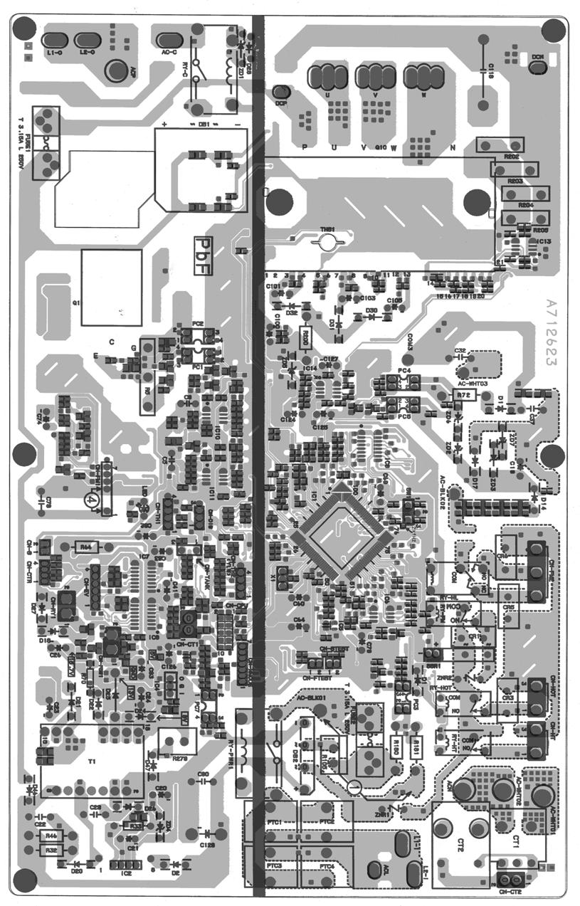
22 22

23 Power Printed Circuit Board 23

24 Noise Filter Printed Circuit Board 24
25 11 Installation Instruction Select The Best Location INDOOR UNIT There should not be any heat source or steam near the unit. There should not be any obstacles blocking the air circulation. A place where air circulation in the room is good. A place where drainage can be easily done. A place where noise prevention is taken into consideration. Do not install the unit near the door way. Ensure the spaces indicated by arrows from the wall, ceiling, fence or other obstacles. Recommended installation height for indoor unit shall be at least 2.5 m Indoor/Outdoor Unit Installation Diagram OUTDOOR UNIT If an awning is built over the unit to prevent direct sunlight or rain, be careful that heat radiation from the condenser is not obstructed. There should not be any animal or plant which could be affected by hot air discharged. Keep the spaces indicated by arrows from wall, ceiling, fence or other obstacles. Do not place any obstacles which may cause a short circuit of the discharged air. If piping length is over 10 m, additional refrigerant should be added as shown in the table. Model Piping size Gas Liquid Rated Length (m) Max Elevation (m) Min. Piping Length (m) Max. Piping Length (m) Additional Refrigerant (g/m) E24GK 5/8 1/ E28GK 5/8 1/ Example : For E24GK If the unit is installed at a 20 m distance, the quantity of additional refrigerant should be 300 g... (20-10) m x 30 g/m = 300 g. 25

26 11.3. Indoor Unit HOW TO FIX INSTALLATION PLATE The mounting wall is strong and solid enough to prevent it from the vibration TO DRILL A HOLE IN THE WALL AND INSTALL A SLEEVE OF PIPING 1. Insert the piping sleeve to the hole. 2. Fix the bushing to the sleeve. 3. Cut the sleeve until it extrudes about 15 mm from the wall. Caution When the wall is hollow, please be sure to use the sleeve for tube ass y to prevent dangers caused by mice biting the connecting cable. The centre of installation plate should be at more than 550 mm at right and left of the wall. The distance from installation plate edge to ceiling should more than 67 mm. From installation plate left edge to unit s left side is 47 mm. From installation plate right edge to unit s right is 73 mm. 4. Finish by sealing the sleeve with putty or caulking compound at the final stage. : For left side piping, piping connection for liquid should be about 126 mm from this line. : For left side piping, piping connection for gas should be about 174 mm from this line. : For left side piping, piping connection cable should be about 984 mm from this line. 1. Mount the installation plate on the wall with 5 screws or more. (If mounting the unit on the concrete wall consider using anchor bolts.) Always mount the installation plate horizontally by aligning the marking-off line with the thread and using a level gauge. 2. Drill the piping plate hole with ø70 mm hole-core drill. Line according to the arrows marked on the lower left and right side of the installation plate. The meeting point of the extended line is the centre of the hole. Another method is by putting measuring tape at position as shown in the diagram above. The hole centre is obtained by measuring the distance namely 150 mm and 125 mm for left and right hole respectively. Drill the piping hole at either the right or the left and the hole should be slightly slanted to the outdoor side INDOOR UNIT INSTALLATION 1. For the right rear piping 2. For the right and right bottom piping 26

27 3. For the embedded piping (This can be used for left rear piping and left bottom piping also.) 27

28 CONNECT THE CABLE TO THE INDOOR UNIT 1. The inside and outside connecting cable can be connected without removing the front grille. 2. Connecting cable between indoor unit and outdoor unit shall be approved polychloroprene sheathed mm 2 flexible cord, type designation 245 IEC 57 or heavier cord. Ensure the colour of wires of outdoor unit and the terminal Nos. are the same to the indoor s respectively. Earth lead wire shall be longer than the other lead wires as shown in the figure for the electrical safety in case of the slipping out of the cord from the anchorage. Secure the cable onto the control board with the holder (clamper). Terminal screw Tightening torque N cm (kgf cm) M3 69 ~ 98 (7-10) M4 157 ~ 196 (16-20) M5 196 ~ 245 (20-25) 28
29 11.4. Outdoor Unit INSTALL THE OUTDOOR UNIT After selecting the best location, start installation according to Indoor/Outdoor Unit Installation Diagram. 1. Fix the unit on concrete or rigid frame firmly and horizontally by bolt nut (ø10 mm). 2. When installing at roof, please consider strong wind and earthquake. Please fasten the installation stand firmly with bolt or nails CONNECTING THE PIPING Connecting The Piping To Indoor Unit Please make flare after inserting flare nut (locate at joint portion of tube assembly) onto the copper pipe. (in case of using long piping). Connect the piping Align the center of piping and sufficiently tighten the flare nut with fingers. Further tighten the flare nut with torque wrench in specified torque as stated in the table. Model Piping size (Torque) Gas Liquid E24GK, E28GK 5/8 [65 N m] 1/4 [18 N m) Connecting The Piping To Outdoor Unit Decide piping length and then cut by using pipe cutter. Remove burrs from cut edge. Make flare after inserting the flare nut (locate at valve) onto the copper pipe. Align center of piping to valves and then tighten with torque wrench to the specified torque as stated in the table. Local pipes can project in any of four directions. Make holes in the pipe panels for the pipes to pass through. Be sure to install the pipe panels to prevent rain from getting inside the outdoor unit. [Removing the service panel]. (1) Remove the two mounting screws. (2) Slide the service panel downward to release the pawls. After this, pull the service panel toward you to remove it. CUTTING AND FLARING THE PIPING 1. Please cut using pipe cutter and then remove the burrs. 2. Remove the burrs by using reamer. If burrs is not removed, gas leakage may be caused. Turn the piping end down to avoid the metal powder entering the pipe. 3. Please make flare after inserting the flare nut onto the copper pipes. 29
30 EVACUATION OF THE EQUIPMENT WHEN INSTALLING AN AIR CONDITIONER, BE SURE TO EVACUATE THE AIR INSIDE THE INDOOR UNIT AND PIPES in the following procedure. 1. Connect a charging hose with a push pin to the Low side of a charging set and the service port of the 3-way valve. Be sure to connect the end of the charging hose with the push pin to the service port. 2. Connect the center hose of the charging set to a vacuum pump with check valve, or vacuum pump and vacuum pump adaptor. 3. Turn on the power switch of the vacuum pump and make sure that the needle in the gauge moves from 0 cmhg (0 MPa) to -76 cmhg (-0.1 MPa). Then evacuate the air approximately ten minutes. 4. Close the Low side valve of the charging set and turn off the vacuum pump. Make sure that the needle in the gauge does not move after approximately five minutes. Note: BE SURE TO FOLLOW THIS PROCEDURE IN ORDER TO AVOID REFRIGERANT GAS LEAKAGE. 5. Disconnect the charging hose from the vacuum pump and from the service port of the 3-way valve. 6. Tighten the service port caps of the 3-way valve at a torque of 18 N m with a torque wrench. 7. Remove the valve caps of both of the 2-way valve and 3-way valve. Position both of the valves to OPEN using a hexagonal wrench (4 mm). 8. Mount valve caps onto the 2-way valve and the 3-way valve. Be sure to check for gas leakage. CAUTION If gauge needle does not move from 0 cmhg (0 MPa) to -76 cmhg (-0.1 MPa), in step above take the following measure: If the leak stops when the piping connections are tightened further, continue working from step. If the leak does not stop when the connections are retightened, repair the location of leak. Do not release refrigerant during piping work for installation and reinstallation. Take care of the liquid refrigerant, it may cause frostbite. 30

31 CONNECT THE CABLE TO THE OUTDOOR UNIT (FOR DETAIL REFER TO WIRING DIAGRAM AT UNIT) 1. Remove the control board cover from the unit by loosening the screw. 2. Connecting cable between indoor unit and outdoor unit shall be approved polychloroprene sheathed 4 x 2.5 mm 2 flexible cord, type designation 245 IEC 57 or heavier cord. 3. Secure the cable onto the control board with the holder (clamper). 4. Cable connection to the power supply through knife switch (Disconnecting means). Connect the approved polychloroprene sheathed power supply cable (3 x 4.0 mm 2 ), type designation 245 IEC 57 or heavier cord to the terminal board, and connect the other end of the cable to knife switch (Disconnecting means). 5. Select required direction and apply protective bushing provided in accessories to protect cables from sharp edges. 6. Once all wiring work has been completed, tie the wires and cord together with the binding strap so that they do not touch other parts such as the compressor and pipes. Note: Knife switch (Disconnecting means) should have minimum 3.5 mm contact gap. Secure the cable onto the control board with the holder (clamper). 31
32 12 Operation And Function Basic Function Inverter control, which equipped with a microcomputer in determining the most suitable operating mode as time passes, automatically adjusts output power for maximum comfort always. In order to achieve the suitable operating mode, the microcomputer maintains the set temperature by measuring the temperature of the environment and performing temperature shifting. The compressor at outdoor unit is operating following the frequency instructed by the microcomputer at indoor unit that judging the condition according to internal setting temperature and intake air temperature Internal Setting Temperature Once the operation starts, remote control setting temperature will be taken as base value for temperature shifting processes. These shifting processes are depending on the air conditioner settings and the operation environment. The final shifted value will be used as internal setting temperature and it is updated continuously whenever the electrical power is supplied to the unit Airflow Direction 1. There are two types of airflow, vertical airflow (directed by horizontal vane) and horizontal airflow (directed by vertical vanes). 2. Control of airflow direction can be automatic (angles of direction is determined by operation mode, heat exchanger temperature and intake air temperature) and manual (angles of direction can be adjusted using remote control). Vertical Airflow Operation Mode Airflow Direction Vane Angle ( ) Heating Auto with Heat Exchanger A 19 B 49 Temperature C 8 D 8 Manual Cooling and Soft Dry Auto 8 ~ 38 Manual Mode Judgment in Auto Auto 8 Manual
33 1. Automatic vertical airflow direction can be set using remote control; the vane swings up and down within the angles as stated above. For heating mode operation, the angle of the vane depends on the indoor heat exchanger temperature as Figure 1 below. When the air conditioner is stopped using remote control, the vane will shift to close position. 2. Manual vertical airflow direction can be set using remote control; the angles of the vane are as stated above and the positions of the vane are as Figure 2 below. When the air conditioner is stopped using remote control, the vane will shift to close position. Horizontal Airflow 1. Automatic horizontal airflow direction can be set using remote control; the vane swings left and right within the angles as stated below. For heating mode operation, the angle of the vane depends on the indoor heat exchanger temperature as Figure 1 below. Operation Mode Vane Angle ( ) A 18 ~ 62 Heating, with heat exchanger temperature B 90 Cooling and Soft Dry 18 ~ Manual horizontal airflow direction can be set using remote control; the angles of the vane are as stated below and the positions of the vane are as Figure 2 above. Pattern Airflow Direction Patterns at Remote Control Vane Angle ( ) Quiet operation (Cooling Mode/Cooling area of Soft Dry Mode) A. Purpose To provide quiet cooling operation compare to normal operation. B. Control condition a. Quiet operation start condition When quiet button at remote control is pressed. Quiet LED illuminates. 33
34 b. Quiet operation stop condition 1. When one of the following conditions is satisfied, quiet operation stops: a. Powerful button is pressed. b. Stop by OFF/ON switch. c. Timer off activates. d. Quiet button is pressed again. 2. When quiet operation is stopped, operation is shifted to normal operation with previous setting. 3. When fan speed is changed, quiet operation is shifted to quiet operation of the new fan speed. 4. When operation mode is changed, quiet operation is shifted to quiet operation of the new mode. 5. During quiet operation, if timer on activates, quiet operation maintains. 6. After off, when on back, quiet operation is not memorised. C. Control contents 1. Fan speed is changed from normal setting to quiet setting of respective fan speed. This is to reduce sound of Hi, Me, Lo for 3dB. 2. Fan speed for quiet operation is -100 rpm from setting fan speed Quiet operation under Soft Dry operation (Dry area at Soft Dry Mode) Automatic Fan Speed (Soft dry operation) Manual Fan Speed (Soft dry operation) Quiet operation (Heating) A. Purpose To provide quiet heating operation compare to normal operation. B. Control condition a. Quiet operation start condition When quiet button at remote control is pressed. Quiet LED illuminates. b. Quiet operation stop condition 1. When one of the following conditions is satisfied, quiet operation stops: a. Powerful button is pressed. b. Stop by OFF/ON switch. c. Timer off activates. d. Quiet button is pressed again. 2. When quiet operation is stopped, operation is shifted to normal operation with previous setting. 3. When fan speed is changed, quiet operation is shifted to quiet operation of the new fan speed. 4. When operation mode is changed, quiet operation is shifted to quiet operation of the new mode, except fan only mode. 5. During quiet operation, if timer on activates, quiet operation maintains. 6. After off, when on back, quiet operation is not memorised. 34
35 C. Control contents a. Fan Speed manual 1. Fan speed is changed from normal setting to quiet setting of respective fan speed. This is to reduce sound of Hi, Me, Lo for 3dB. 2. Fan speed for quiet operation is -100 rpm from setting fan speed. 3. Fan Speed Auto If FM Lo -100 rpm reduce from normal Heating Auto Fan Speed If FM Lo maintain RPM Indoor FM RPM depends on pipe temp sensor of indoor heat exchanger Powerful Mode Operation When the powerful mode is selected, the internal setting temperature will shift to achieve the setting temperature quickly. (a) Cooling Operation (b) Soft Dry Operation (c) Heating Operation ON Timer Control ON timer can be set using remote control, the unit with timer set will start operate earlier than the setting time. This is to provide a comfortable environment when reaching the set ON time. Seventy minutes before the set time, indoor (at fan speed of Lo-) and outdoor fan motor start operate for 30 seconds to determine the indoor intake air temperature and outdoor air temperature in order to judge the operation starting time. From the above judgment, the decided operation will start operate earlier than the set time as shown below. 35
36 12.6. OFF Timer Control OFF timer can be set using remote control, the unit with timer set will stop operate at set time Auto Restart Control 1. When the power supply is cut off during the operation of air conditioner, the compressor will re-operate within three to four minutes (there are 10 patterns between 2 minutes 58 seconds and 3 minutes 52 seconds to be selected randomly) after power supply resumes. 2. This type of control is not applicable during ON/OFF Timer setting Indication Panel LED POWER TIMER QUIET POWERFUL e-ion PATROL SENSOR Color Green Orange Orange Orange Blue Blue Light ON Operation ON Quiet Setting ON Quiet Mode ON Powerful Mode ON e-ion ON PATROL ON Light OFF Operation OFF Quiet Setting OFF Quiet Mode OFF Powerful Mode OFF e-ion OFF PATROL OFF Note: If POWER LED is blinking, the possible operation of the unit are Hot Start, during Deice operation, operation mode judgment, or ON timer sampling. If Timer LED is blinking, there is an abnormality operation occurs. If e-ion LED is blinking, there is an abnormality of e-ion occurs. If PATROL LED is blinking, there is a gas sensor error detection Patrol Operation A. Purpose To monitor air dirtiness level by using gas sensor and activates e-ion operation whenever air is dirty. B. Control Condition a. Patrol operation start condition When the unit operation is started with OFF/ON button. When the unit stops, Patrol button is pressed, Patrol individual operation will start. During cooling only operation, Patrol button is pressed. 36


37 b. Patrol operation stop condition When any of the following condition is fulfilled: When OFF/ON button is pressed. During any operation with Patrol, Patrol button is pressed again. When e-ion button is pressed. When OFF Timer activates. c. Patrol operation disable To disable the Patrol Operation during unit start (default) with OFF/ON button, press Patrol button and hold for 5 seconds, then release. To disable the Patrol Operation, press Patrol button and hold for 15 seconds, then release. C. Control Content a. Gas Sensor Control First 2 minutes from Patrol function activates is stabilization time, during stabilization time, no air dirtiness level is monitored. The Air Dirtiness level is set to level 2. After that, gas sensor starts to record the resistance value at fixed interval. Higher resistance value indicates cleaner air. The air dirtiness level is monitored by comparing the current resistance value with maximum resistance value from time to time to get the Air Dirtiness Value. There are 3 air dirtiness levels, based on the Air Dirtiness Value: - Air Dirtiness level 0: Clean - Air Dirtiness level 1: Moderate - Air Dirtiness level 2: Contaminated Dirtiness level sensitivity adjustment It is possible to change the gas sensor sensitivity, where the Threshold value (G1 ~ G4) will be shifted accordingly: 1. Press and release SET buttton. 2. Press Timer increment / Timer decrement button to select sensitivity. (Low Standard (Default) High) 3. Confirm setting by pressing Timer Set button. LCD returned to original display after 2 seconds. 4. LCD returned to original display if remote control does not operate for 30 seconds. b. e-ion Control When dirtiness level is 1 or 2, e-ion operation starts. If dirtiness level improves from level 2 to level 1, the unit carries out level change after 60 seconds. When dirtiness level returns to level 0 continuously for 10 minutes or more, e-ion operation stops. Dirtiness Level Shift For Auto Fan Speed, the fan speed increased based on dirtiness level: c. Indoor Fan Control During any operation mode combines with Patrol operation, fan speed follows respective operation mode. During Patrol individual operation if e-ion starts, only Auto Fan Speed and no Powerful operation is allowed. Even if Fan Speed button is pressed, no signal is sent to air conditioner, and no change on LCD display. During Patrol individual operation if e-ion stops, Indoor Fan stop operation. 37
38 d. Airflow direction (Horizontal, Vertical) Control During any operation mode combines with Patrol operation, airflow direction follows respective operation mode. During Patrol individual operation if e-ion starts, only Auto Air Swing is allowed. Even if Air Swing button is pressed, no signal is sent to air conditioner, and no change on LCD display. During Patrol individual operation if e-ion stops, Airflow direction louver closed. e. Indicator When Patrol operation starts, Patrol Sensor indicator ON. When e-ion operation starts based on dirtiness level, e-ion indicator ON. f. Remote Control Receiving Sound Normal Operation Patrol Mode Patrol Mode Stop Patrol Mode Stop Normal Operation Patrol : : : : Beep Long Beep Beep Beep g. Timer Control When ON timer activates when unit stops, previous operation resumes without Patrol operation. When ON timer activates during any operation, no change and carry on current operation. When OFF timer activates during any operation, all operation stops. h. Power failure During Patrol individual operation, if power failure occurs, after power resumes, Patrol individual operation resumes immediately. During combination operation, if power failure occurs, after power resumes combination operation resume immediately e-ion Operation A. Purpose This operation provides clean air by producing negative ions to attract dust captured at the positively charged e-ion filters. B. Control Condition a. e-ion operation start condition During unit running at any operation mode, if e-ion button is pressed, combination operation (operation mode + e-ion operation) starts. During unit is OFF, if e-ion button is pressed, e-ion individual operation starts. b. e-ion operation stop condition When OFF/ON button is pressed to stop the operation. When e-ion button is pressed again. When Patrol button is pressed. When OFF Timer activates. 38
39 c. e-ion operation pause condition When indoor fan stop (during deice, odor cut control, thermostat off, etc.). e-ion operation resume after indoor fan restarts. When indoor intake temperature 40 C. e-ion operation resume after indoor intake temperature < 40 C continuously for 30 minutes. C. Control Content a. Indoor fan control During any operation mode combines with e-ion operation, fan speed follows respective operation mode. During e-ion individual operation - only Auto Fan Speed and no Powerful operation is allowed. Even if Fan Speed button is pressed, no signal is sent to air conditioner, and no change on LCD display. Auto Fan Speed for e-ion operation switches between HLo and CLo at pattern below: b. Airflow direction control During any operation mode combines with e-ion operation, airflow direction follows respective operation mode. During e-ion individual operation, only Auto Air Swing is allowed. Even if Air Swing button is pressed, no signal is sent to air conditioner, and no change on LCD display. c. Timer control When ON timer activates when unit stops, previous operation resumes without e-ion operation. When ON timer activates during any operation, no change and carry on current operation. When OFF timer activates during any operation, all operation stops. d. Indicator When e-ion operation starts, e-ion indicator ON. e. e-ion Check Mode To check if e-ion is malfunctioning, during e-ion operation press e-ion button for 15 seconds and release to enter e-ion Check Mode and supplies power to the e-ion Air Purifying System. If abnormal discharge is detected at filter (short-circuited) due to water or dust adhesion, etc., the e-ion indicator blinks immediately. f. Power failure During e-ion individual operation, if power failure occurs, after power resumes, e-ion individual operation resumes immediately. During combination operation, if power failure occurs, after power resumes, combination operation resume immediately. g. Error Detection Control When e-ion indicator blink, it indicates error listed below: i. e-ion Air Purifying system main connector to PCB is open: Judgement Method During e-ion operation (include during Patrol operation), e-ion Air Purifying system main connector to PCB is opened. Troubleshooting Methods Connect the connector or stop operation (include during Patrol operation) to cancel the blinking. ii. Abnormal Discharge Judgement Method During e-ion operation, when feedback voltage is -Lo (at microcontroller) is detected, it is judged abnormal discharge and stops power supplies to the e-ion Air Purifying system. The unit retries after 30 minutes and repeat for 24 times. (not applicable for e-ion Check Mode) 39
40 Troubleshooting Method Press e-ion button or OFF/ON button to stop the operation and check the e-ion Air Purifying system main connector to PCB. After that, press e-ion button again to confirm the e-ion indicator not blinking. The 24 times counter will be clear after 10 minutes of normal operation or when operation stops. Error Reset Method Press OFF/ON button to OFF the operation. Press AUTO OFF/ON button at indoor unit to OFF the operation. OFF Timer activates. Press e-ion button during e-ion individual mode. Power supply reset. iii. e-ion breakdown Judgement Method When hi-feedback voltage (at microcontroller) supplied to filter during e-ion stop, due to PCB or filter s high voltage power supply damage. Operations except e-ion continue. Both Timer indicator and e-ion indicator blink. Troubleshooting Method Press e-ion button or OFF/ON button to stop the operation. Change main circuit board or filter s high voltage power supply. When lo-feedback voltage supplied to e-ion Air Purifying system during e-ion operation, e-ion indicator and Timer indicator stop blinking. 40
41 13 Protection Control Protection Control For All Operations Time Delay Safety Control 1. The compressor will not start for three minutes after stop of operation. 2. This control is not applicable if the power supply is cut off and on again or after 4-way valve deices condition Seconds Forced Operation 1. Once the compressor starts operation, it will not stop its operation for 30 seconds. 2. However, it can be stopped using remote control or Auto Switch at indoor unit Total Running Current Control 1. When the outdoor unit total running current (AC) exceeds X value, the frequency instructed for compressor operation will be decreased. 2. If the running current does not exceed X value for five seconds, the frequency instructed will be increased. 3. However, if total outdoor unit running current exceeds Y value, compressor will be stopped immediately for 2 minutes. E24GK E28GK Operation Mode X (A) Y (A) X (A) Y (A) Cooling/Soft Dry (A) Cooling/Soft Dry (B) Cooling/Soft Dry (C) Heating The first 30 minutes of cooling operation, (A) will be applied IPM (Power transistor) Prevention Control A. Overheating Prevention Control 1. When the IPM temperature rises to 110 C, compressor operation will stop immediately. 2. Compressor operation restarts after three minutes the temperature decreases to 95 C. B. DC Peak Current Control 1. When electric current to IPM exceeds set value of 30.0 ± 5.0 A, the compressor will stop operate. Then, operation will restart after three minutes. 2. If the set value is exceeded again more than 30 seconds after the compressor starts, the operation will restart after two minutes. 3. If the set value is exceeded again within 30 seconds after the compressor starts, the operation will restart after one minute. If this condition repeats continuously for seven times, all indoor and outdoor relays will be cut off. 41
42 Compressor Overheating Prevention Control Instructed frequency for compressor operation will be regulated by compressor top temperature. The changes of frequency are as below figure Protection Control For Cooling & Soft Dry Operation Outdoor Air Temperature Control The compressor operating frequency is regulated in accordance to the outdoor air temperature as shown in the diagram below Cooling Overload Control i. Pipe temperature limitation/restriction Detects the Outdoor pipe temperature and carry out below restriction/limitation (Limit the compressor Operation frequency) The compressor stop if outdoor pipe temperature exceeds 65 C. If the compressor stops 4 times in 20 minutes, Timer LED blinking (F95: outdoor high pressure rise protection) ii. Electrical part temperature rise protection control To prevent electrical component temperature rise during cooling overload. Judgement condition is by outdoor temperature (sampled every 10s). 42
43 Control contents: Outdoor fan speed (switch to zone A and B minimum fan speed). Outdoor total current (zone C) higher than the specified. Cancellation condition: When one of above is not satisfied Freeze Prevention Control 1. When indoor heat exchanger temperature is lower than 2 C continuously for six minutes, compressor will stop operating. 2. Compressor will resume its operation three minutes after the indoor heat exchanger is higher than 10 C. 3. At the same time, indoor fan speed increase +40 rpm compared to its normal operation. 4. If indoor heat exchanger temperature is higher than 10 C for five minutes, the fan speed will return to its normal operation Protection Control For Heating Operation Intake Air Temperature Control Compressor will operate at rated freq. or less respectively if either one of the below conditions occur: 1. When the indoor intake air temperature is above 10 C and remote control setting fan speed is lower Me-. 2. When the indoor intake air temperature is 30 C or above Outdoor Air Temperature Control The compressor operating frequency is regulated in accordance to the outdoor air temperature as shown in the below figures. This control will begin one minute after the compressor starts. 43
44 Overload Protection Control The compressor operating frequency is regulated in accordance to indoor heat exchanger temperature as shown in below figures. 44
45 14 Servicing Mode Auto OFF/ON Button 1. AUTO OPERATION MODE The Auto operation will be activated immediately once the Auto OFF/ON button is pressed. This operation can be used to operate air conditioner with limited function if remote control is misplaced or malfunction. 2. TEST RUN OPERATION (FOR PUMP DOWN/SERVICING PURPOSE) The Test Run operation will be activated if the Auto OFF/ON button is pressed continuously for more than 5 seconds. A beep sound will occur at the fifth seconds, in order to identify the starting of Test Run operation (Forced cooling operation). Within 5 minutes after Forced cooling operation start, the Auto OFF/ON button is pressed for more than 5 seconds. A 2 beep sounds will occur at the fifth seconds, in order to identify the starting of Forced heating operation. The Auto OFF/ON button may be used together with remote control to set / change the advance setting of air conditioner operation. 3. REMOTE CONTROL NUMBER SWITCH MODE The Remote Control Number Switch Mode will be activated if the Auto OFF/ON button is pressed continuously for more than 11 seconds (3 beep sounds will occur at 11th seconds to identify the Remote Control Number Switch Mode is in standby condition) and press any button at remote control to transmit and store the desired transmission code to the EEPROM. For transmission code selection explanation, please refer to Select Remote Control Transmission Code. 4. REMOTE CONTROL RECEIVING SOUND OFF/ON MODE The Remote Control Receiving Sound OFF/ON Mode will be activated if the Auto OFF/ON button is pressed continuously for more than 16 seconds (4 beep sounds will occur at 16th seconds to identify the Remote Control Receiving Sound Off/On Mode is in standby condition) and press AC Reset button and then press Check button at remote control. Press Auto OFF/ON button to toggle remote control receiving sound. - Short beep : Turn OFF remote control receiving sound. - Long beep : Turn ON remote control receiving sound. After Auto OFF/ON Button is pressed, the 20 seconds counter for Remote Control Receiving Sound OFF/ON Mode is restarted Select Remote Control Transmission Code There are 4 types of remote control transmission code could be selected and stored in EEPROM of indoor unit. The indoor unit will only operate when received signal with same transmission code from remote control. This could prevent signal interference when there are 2 or more indoor units installed nearby together. To change remote control transmission code, short or open jumpers at the remote control printed circuit board. 45
46 Remote Control Printed Circuit Board Jumper A (J-A) Jumper B (J-B) Remote Control No. Short Open A (Default) Open Open B Short Short C Open Short D Remote Control Button SET BUTTON To check current remote control transmission code - Press for more than 10 seconds. To change the air quality sensor sensitivity - Press and release with pointer. - Press the Timer Decrement button to select sensitivity: 1. Low Sensitivity 2. Standard (Default) 3. Hi Sensitivity - Confirm setting by pressing Timer Set button, a Beep sound will be heard. LCD returns to original display after 2 seconds. - LCD returns to original display if remote control does not operate for 30 seconds CLOCK BUTTON To change the remote control s time format - Press for more than 5 seconds RESET (RC) To clear and restore the remote control setting to factory default - Press once to clear the memory RESET (AC) To restore the unit s setting to factory default - Press once to restore the unit s setting TIMER To change indoor unit indicator s LED intensity - Press continuously for 5 seconds TIMER To change remote control display from Degree Celsius to Degree Fahrenheit. - Press continuously for 10 seconds. 46
47 15 Troubleshooting Guide Refrigeration Cycle System In order to diagnose malfunctions, make sure that there are no electrical problems before inspecting the refrigeration cycle. Such problems include insufficient insulation, problem with the power source, malfunction of a compressor and a fan. The normal outlet air temperature and pressure of the refrigeration cycle depends on various conditions, the standard values for them are shown in the table on the right. 47
48 15.2. Relationship Between The Condition Of The Air Conditioner And Pressure And Electric Current Condition of the Cooling Mode air conditoner Low Pressure High Pressure Electric current during operation Heating Mode Low Pressure High Pressure Electric current during operation Insufficient refrigerant (gas leakage) Clogged capillary tube or Strainer Short circuit in the indoor unit Heat radiation deficiency of the outdoor unit Inefficient compression Carry out the measurements of pressure, electric current, and temperature fifteen minutes after an operation is started. 48
49 15.3. Breakdown Self Diagnosis Function Self Diagnosis Function (Three Digits Alphanumeric Code) Once abnormality has occurred during operation, the unit will stop its operation, and Timer LEDs blink. Although Timer LED goes off when power supply is turned off, if the unit is operated under a breakdown condition, the LED will light up again. In operation after breakdown repair, the Timer LED will no more blink. The last error code (abnormality) will be stored in IC memory. To make a diagnosis 1. Timer LED start to blink and the unit automatically stops the operation. 2. Press the CHECK button on the remote controller continuously for 5 seconds will be displayed on the remote controller display. Note: Display only for - -. (No transmitting signal, no receiving sound and no Power LED blinking.) 4. Press the TIMER or button on the remote controller. The code H00 (no abnormality) will be displayed and signal will be transmitted to the main unit. 5. Every press of the button (up or down) will increase abnormality numbers and transmit abnormality code signal to the main unit. 6. When the latest abnormality code on the main unit and code transmitted from the remote controller are matched, power LED will light up for 30 seconds and a beep sound (continuously for 4 seconds) will be heard. If no codes are matched, power LED will light up for 0.5 seconds and no sound will be heard. 7. The breakdown diagnosis mode will be canceled by pressing the CHECK button continuously for 5 seconds or without any operation the remote control for 30 seconds. 8. The LED will be off if the unit is turned off or the AC button on the main unit is pressed. To display memorized error (Protective operation) status: 1. Turn power on. 2. Press the CHECK button on the remote controller continuously for 5 seconds will be displayed on the remote controller display. Note: Display only for - -. (No transmitting signal, no receiving sound and no Power LED blinking.) 4. Press the TIMER or button on the remote controller. The code H00 (no abnormality) will be displayed and signal will be transmitted to the main unit. The power LED lights up. If no abnormality is stored in the memory, three beeps sound will be heard. 5. Every press of the button (up or down) will increase abnormality numbers and transmit abnormality code signal to the main unit. 6. When the latest abnormality code on the main unit and code transmitted from the remote controller are matched, power LED will light up for 30 seconds and a beep sound (continuously for 4 seconds) will be heard. If no codes are matched, power LED will light up for 0.5 seconds and no sound will be heard. 7. The breakdown diagnosis mode will be canceled unless pressing the CHECK button continuously for 5 seconds or operating the unit for 30 seconds. 8. The same diagnosis can be repeated by turning power on again. To clear memorized error (Protective operation) status after repair: 1. Turn power on. 2. Press the AUTO button for 5 seconds (A beep receiving sound) on the main unit to operate the unit at Forced Cooling Operation mode. 3. Press the CHECK button on the remote controller for about 1 second with a pointed object to transmit signal to main unit. A beep sound is heard from main unit and the data is cleared. Temporary Operation (Depending on breakdown status) 1. Press the AUTO button (A beep receiving sound) on the main unit to operate the unit. (Remote control will become possible.) 2. The unit can temporarily be used until repaired. Error Code Operation Temporary items H23 Cooling Emergency Operation with limited H27, H28 Cooling, Heating power 49
50 15.4. Error Codes Table Diagnosis display Abnormality / Protection control Abnormality Judgement Emergency operation Primary location to verify H00 No abnormality detected Normal operation H11 Indoor / outdoor abnormal communication > 1 min after starting operation Indoor fan operation only Internal / external cable connections Indoor / Outdoor PCB H12 Connection capability rank abnormal H14 H15 H16 Indoor intake air temperature sensor abnormality Outdoor compressor temperature sensor abnormality Outdoor Current Transformer open circuit Note: O - Frequency measured and fan speed fixed. Continue for 5 sec. Intake air temperature sensor (defective or disconnected) Continue for 5 sec. Compressor temperature sensor (defective or disconnected) Outdoor PCB IPM (Power transistor) module H19 Indoor fan motor merchanism lock Indoor PCB Fan motor H23 Indoor heat exchanger temperature sensor abnormality Continue for 5 sec. O (Cooling only) H25 E-Ion breakdown Indoor PCB E-Ion PCB H27 H28 H30 Outdoor air temperature sensor abnormality Outdoor heat exchanger temperature sensor abnormality Discharge temperature sensor abnormality Heat exchanger temperature sensor (defective or disconnected) Continue for 5 sec. O Outdoor temperature sensor (defective or disconnected) Continue for 5 sec. O Outdoor heat exchanger temperature sensor (defective or disconnected) H33 Indoor/Outdoor wrong connection Indoor/Outdoor supply voltage H38 Indoor/Outdoor mismatch H58 Abnormal gas sensor Continue for 6 hours Gas sensor (defective or disconnected) H97 Outdoor Fan Motor lock abnormality Outdoor PCB Outdoor Fan Motor H98 Indoor high pressure protection Air filter dirty Air circulation short circuit H99 Indoor heat exchanger anti-freezing protection Insufficient refrigerant Air filter dirty F11 Cooling / Heating cycle changeover abnormality 4 times occurance within 30 minutes F90 PFC control 4 times occurance within 10 minutes F91 Refrigeration cycle abnormality 7 times occurance continuously F93 Outdoor compressor abnormal revolution 4 times occurance within 20 minutes F95 Cool high pressure protection 4 times occurance within 20 minutes F96 F97 IPM (power transistor) overheating protection Outdoor compressor overheating protection 4 times occurance within 20 minutes F98 Total running current protection 3 times occurance within 20 minutes F99 Outdoor Direct Current (DC) peak detection 7 times occurance continuously 4-way valve V-coil Voltage at PFC No refrigerant (3-way valve is closed) Outdoor compressor Outdoor refrigerant circuit Excess refrigerant Improper heat radiation IPM (Power transistor) Insufficient refrigerant Compressor Excess refrigerant Improper heat radiation Outdoor PCB IPM (Power transistor) Compressor The memory data of error code is erased when the power supply is cut off, or press the Auto Switch until beep sound heard following by pressing the CHECK button at Remote Control. Although operation forced to stop when abnormality detected, emergency operation is possible for certain errors (refer to Error Codes Table) by using Remote Control or Auto Switch at indoor unit. However, the Remote Control signal receiving sound is changed from one beep to four beep sounds. 50

 Remove the Front Grille by releasing the 3 hooks at the top of the Front Grille.")
 Fig. 1 Fig. 2 16.1.2. To remove the Main Electronic Controller Release the 2 screws for the earth wire. (Fig. 3) Pull out 2 terminal wires (Red and Black) from the Terminal Board. (Fig. 3) Detach the connector Indicator and release the Indicator.")
51 16 Disassembly and Assembly Instructions High voltages are generated in the electrical parts area by the capacitor. Ensure that the capacitor has discharged sufficiently before proceeding with repair work. Failure to heed this caution may result in electric shocks Indoor Electronic Controllers, Cross Flow Fan And Indoor Fan Motor Removal Procedures To remove the Front Grille Lift to open the vertical vent gently. Remove the 3 caps and 3 screws at the bottom of discharge vent. (Fig. 1) Remove the Front Grille by releasing the 3 hooks at the top of the Front Grille. Hold both sides of the Front Grille and remove it by pulling up and towards you gently. (Fig. 1) Unhook the tabs at the Control Board to remove the Control Board Cover. (Fig. 2) Release the Particular Piece. (Fig. 2) Fig. 1 Fig To remove the Main Electronic Controller Release the 2 screws for the earth wire. (Fig. 3) Pull out 2 terminal wires (Red and Black) from the Terminal Board. (Fig. 3) Detach the connector Indicator and release the Indicator. (Fig. 3) Release the 2 Particular Piece. (Fig. 3) Release the screw Holder Terminal Board. (Fig. 3) Release the 2 connector E-Ion. (Fig. 3) Fig. 3 51
 Fig.")
 Release the CN-CLN connector. (Fig.")
 Release the CN-STM2 connector. (Fig. 5) Fig. 5 16.1.3.")

52 Release the hooks that hold the Main Electronic Controller and pull out the Main Electronic Controller. (Fig. 4) Fig. 4 Release the CN-DATA1 connector. (Fig. 5) Release the CN-TH connector. (Fig. 5) Release the CN-CLN connector. (Fig. 5) Release the CN-STM1 connector. (Fig. 5) Release the CN-STM2 connector. (Fig. 5) Fig To remove the Power Electronic Controller Release the hook that hold the Particular Piece and pull out the Power Electronic Controller. (Fig. 6) Fig. 6 Release the AC-303 connector. (Fig. 7) Release the CN-FM connector. (Fig. 7) Fig. 7 52
")

 Fig. 9 16.")

53 To remove the Discharge Grille Pull out the Drain Hose (Behind the Discharge Grille) from outlet to remove the Discharge Grille. (Fig. 8) Fig To remove the Control Board Release the 3 screws (Fig. 9) By pressing down the hook at the left, you will be able to remove the Control Board. (Fig. 9) Fig To remove the Cross Flow Fan and Indoor Fan Motor Remove the screw at the Cross Flow Fan. (Fig. 10) Reminder:- To reinstall the Fan Motor, please adjust the connector location is positioned 90 with Fan Motor before fixing Control Board. (Fig. 10) Fig. 10 Remove the Bearing. (Fig. 11) Remove the screws at the left of the Evaporator. (Fig. 11) Fig
 Fig.")
54 Push up the Evaporator and pull out the Cross Flow Fan from shaft. By then, Fan Motor can be taken out. (Fig. 12) Fig
Air Conditioner CONTENTS CS-E18EKU CU-E18EKU CS-E21EKU CU-E21EKU. Order No: MAC C1
 Order No: MAC0512115C1 CS-E18EKU CU-E18EKU CS-E21EKU CU-E21EKU Air Conditioner CONTENTS Page Page 1 Safety Precautions 3 2 Specification 5 2.1. CS-E18EKU CU-E18EKU 5 2.2. CS-E21EKU CU-E21EKU 7 3 Location
TABLE OF CONTENTS. Air Conditioner CS-NE7GKE CU-NE7GKE CS-NE9GKE CU-NE9GKE CS-NE12GKE CU-NE12GKE
 Order No. MAC0705021C2 Air Conditioner CS-NE7GKE CU-NE7GKE CS-NE9GKE CU-NE9GKE CS-NE12GKE CU-NE12GKE TABLE OF CONTENTS PAGE 1 Safety Precaution ------------------------------------------------ 2 2 Specifications
CU-3E23CBPG, CU- 4E27CBPG,
 Order No. PHAAM0810051C2 Air Conditioner Indoor Unit Outdoor Unit CS-E7JKEW CU-E7JKE CS-E9JKEW CU-E9JKE CS-E12JKEW CU-E12JKE CS-E15JKEW CU-E15JKE CS-E15JKEW CU-E15JKE-1 CS-E7JKEW-3 CU-E7JKE-3 CS-E9JKEW-3
TABLE OF CONTENTS. Air Conditioner. Indoor Unit Outdoor Unit CS-NE9LKE CU-NE9LKE CS-NE12LKE CU-NE12LKE CS-XE9LKE-5 CU-NE9LKE CS-XE12LKE-5 CU-NE12LKE
 Order No. PHAAM1007139C2 Air Conditioner Indoor Unit Outdoor Unit CS-NE9LKE CU-NE9LKE CS-NE12LKE CU-NE12LKE CS-XE9LKE-5 CU-NE9LKE CS-XE12LKE-5 CU-NE12LKE TABLE OF CONTENTS PAGE 1 Safety Precautions-----------------------------------------------
CS-XE9EKE CU-XE9EKE CS-XE12EKE CU-XE12EKE
 Order No. MAC0512111C8 Air Conditioner CS-XE9EKE CU-XE9EKE CS-XE12EKE CU-XE12EKE TABLE OF CONTENTS PAGE 1 Safety Precautions----------------------------------------------- 3 2 Specifications -----------------------------------------------------
TABLE OF CONTENTS. Air Conditioner CS-MRE12MKE
 Order No. PHAAM1103074C8 Indoor Unit CS-MRE7MKE CS-MRE9MKE CS-MRE12MKE Air Conditioner Outdoor Unit CU-2RE15MBE CU-2RE18MBE TABLE OF CONTENTS PAGE 1 Safety Precautions-----------------------------------------------
AUTO COOL DRY FAN SPEED AIR SWING OFF ON TIMER TIMER OFF/ON FAN SPEED MODE TEMP AIR SWING TIMER ON SET OFF CANCEL AC RC SET CHECK CLOCK RESET
 AUTO COOL DRY MODE TIMER ON OFF TIMER OFF/ON TEMP ON TIMER FAN SPEED AIR SWING SET 1 2 3 FAN SPEED AIR SWING OFF CANCEL AC RC SET CHECK CLOCK RESET Order No: PAPAMY1611008CE Indoor Unit CS-MPS9SKH CS-MPS12SKH
CS-E18NKUA CS-E24NKUA CU-E18NKUA CU-E24NKUA TABLE OF CONTENTS WARNING
 Order No: PAPAMY1204088CE Indoor Unit CS-E18NKUA CS-E24NKUA Outdoor Unit CU-E18NKUA CU-E24NKUA WARNING This service information is designed for experienced repair technicians only and is not designed for
CS-UE9PKE CS-UE12PKE CU-UE9PKE CU-UE12PKE TABLE OF CONTENTS WARNING
 Order No: PAPAGZ121215CE Indoor Unit CS-UE9PKE CS-UE12PKE Outdoor Unit CU-UE9PKE CU-UE12PKE WARNING This service information is designed for experienced repair technicians only and is not designed for
CS-RE9JKX-1 CS-RE12JKX-1 CS-RE15JKX-1 CU-RE9JKX-1 CU-RE12JKX-1 CU-RE15JKX-1 TABLE OF CONTENTS WARNING
 Order No: PHA-AG1002007C2 Indoor Unit CS-RE9JKX-1 CS-RE12JKX-1 CS-RE15JKX-1 Outdoor Unit CU-RE9JKX-1 CU-RE12JKX-1 CU-RE15JKX-1 WARNING This service information is designed for experienced repair technicians
CU-YE9MKE CU-YE12MKE CU-YE18MKE CS-YE9MKE CS-YE12MKE CS-YE18MKE TABLE OF CONTENTS WARNING
 Order No: PHA-AG1102003C2 Indoor Unit CS-YE9MKE CS-YE12MKE CS-YE18MKE Outdoor Unit CU-YE9MKE CU-YE12MKE CU-YE18MKE WARNING This service information is designed for experienced repair technicians only and
Destination Europe WARNING
 Order No: PAPAMY1406071CE Indoor Unit CS-E12QD3EAW Outdoor Unit CU-E12QD3EA Destination Europe Please file and use this manual together with the service manual for Model No. CU-2E15PBE CU-2E18PBE CU-3E18PBE
Room Air Conditioner CONTENTS CS-E9BKP CU-E9BKP5 CS-E12BKP CU-E12BKP5. Order No: MAC C2
 Order No: MAC008C Room Air Conditioner CS-E9BKP CU-E9BKP5 CS-EBKP CU-EBKP5 CONTENTS Page Page Features Functions Product Specifications 6 Dimensions 0 5 Refrigeration Cycle Diagram 6 Block Diagram 7 Wiring
Air-to-Water Heatpump
 Order No. PHAAM1006120C2 Air-to-Water Heatpump Indoor Unit Outdoor Unit WH-SDC07C3E5 WH-UD07CE5-A WH-SDC09C3E5 WH-UD09CE5-A WH-SDC12C6E5 WH-UD12CE5-A WH-SDC14C6E5 WH-UD14CE5-A WH-SDC16C6E5 WH-UD16CE5-A
CU-S9NKV-7 CU-S12NKV-7 CU-S18NKV-7 CU-S22NKV-7 CS-S9NKV-7 CS-S12NKV-7 CS-S18NKV-7 CS-S22NKV-7 WARNING
 Order No: PAPAMY1206010CE Indoor Unit CS-S9NKV-7 CS-S12NKV-7 CS-S18NKV-7 CS-S22NKV-7 Outdoor Unit CU-S9NKV-7 CU-S12NKV-7 CU-S18NKV-7 CU-S22NKV-7 WARNING This service information is designed for experienced
Room Air Conditioner CONTENTS CS-E18CKE CU-E18CKE CS-E21CKE CU-E21CKE. Order No. MAC C2
 Order No. MAC00801C Room Air Conditioner CS-E18CKE CU-E18CKE CS-E1CKE CU-E1CKE CONTENTS Page Page 1 Features Functions Product Specifications 6 4 Dimensions 10 5 Refrigeration Cycle Diagram 1 6 Block Diagram
Air Conditioner CONTENTS CS-E9DKEW CU-E9DKE CS-E12DKEW CU-E12DKE. Order No: MAC C2
 Order No: MAC041064C CS-E9DKEW CU-E9DKE CS-E1DKEW CU-E1DKE Air Conditioner CONTENTS Page Page 1 Features Functions 3.1. Remote Control 3.. Indoor Unit 4.3. Outdoor Unit 6 3 Product Specifications 7 3.1.
TABLE OF CONTENTS. Air Conditioner
 Order No. MAC0804027A2 Air Conditioner CS-E9GFEW-2 CU-E9GFE-2 CS-E12GFEW-2 CU-E12GFE-2 CS-E18GFEW-2 CU-E18GFE-2 CU-2E15GBE CU-3E18EBE CU-3E23CBPG CU-4E27CBPG Please file and use this manual together with
Air Conditioner CONTENTS CS-TE9DKE CU-TE9DKE CS-TE12DKE CU-TE12DKE. Order No. RAC C2
 Order No. RAC0502005C2 Air Conditioner CS-TE9DKE CU-TE9DKE CS-TE12DKE CU-TE12DKE CONTENTS Page Page 1 Features 2 2 Functions 3 2.1. Remote Control 3 2.2. Indoor Unit 4 2.3. Outdoor unit 5 3 Product Specifications
Air Conditioner CONTENTS CS-V18DKE CU-V18DKE CS-V24DKE CU-V24DKE. Order No. MAC C2
 Order No. MAC0410044C2 CS-V18DKE CU-V18DKE CS-V24DKE CU-V24DKE Air Conditioner CONTENTS Page Page 1 Features 2 2 Functions 3 2.1. Remote Control 3 2.2. Indoor Unit 4 2.3. Outdoor Unit 5 3 Product Specifications
Operating Instructions Air Conditioner
 F566113 Operating Instructions Air Conditioner Indoor Unit CS-E18HKR CS-E1HKR CS-E4HKR CS-E8HKR Outdoor Unit CU-E18HKR CU-E1HKR CU-E4HKR CU-E8HKR Before operating the unit, read these operating instructions
Operating Instructions Air Conditioner
 F56579 Operating Instructions Air Conditioner Indoor Unit Outdoor Unit CS-E18GKR CS-E1GKR CS-E4GKR CS-E8GKR CU-E18GKR CU-E1GKR CU-E4GKR CU-E8GKR Before operating the unit, read these operating instructions
Air-to-Water Hydromodule + Tank WH-UX12FE5 WH-UD12FE5 WH-UD16FE5. Destination Europe WARNING
 Order : PAPAMY420CE Air-to-Water Hydromodule + Tank Indoor Unit WH-ADC26G6E5 Outdoor Unit WH-UX09FE5 WH-UX2FE5 WH-UD2FE5 WH-UD6FE5 Destination Europe WARNING This service information is designed for experienced
INSTALLATION MANUAL. Split-type Air Conditioner (Cooling and Heating) Indoor Unit AQB18J6WC AQB24J2WC. Outdoor Unit UQB18J6WC UQB24J2WC
 Indoor Unit AQB18J6WC AQB24J2WC. Outdoor Unit UQB18J6WC UQB24J2WC") AQB8J6WC_IM_E_25864 2006.4.4 3:29 PM Page 7 INSTALLATION MANUAL Indoor Unit AQB8J6WC AQB24J2WC Outdoor Unit UQB8J6WC UQB24J2WC ENGLISH FRANÇAIS ESPAÑOL Split-type Air Conditioner (Cooling and Heating)
AQB8J6WC_IM_E_25864 2006.4.4 3:29 PM Page 7 INSTALLATION MANUAL Indoor Unit AQB8J6WC AQB24J2WC Outdoor Unit UQB8J6WC UQB24J2WC ENGLISH FRANÇAIS ESPAÑOL Split-type Air Conditioner (Cooling and Heating)
INSTALLATION MANUAL. Split-type Air Conditioner (Cooling and Heating) Outdoor Unit UQB09JJWC UQB12JJWC. Indoor Unit AQB09JJWC AQB12JJWC
 Outdoor Unit UQB09JJWC UQB12JJWC. Indoor Unit AQB09JJWC AQB12JJWC") AQB09JJ6WC_IM_E_2585 2006.4.17 4:26 PM Page 17 INSTALLATION MANUAL Indoor Unit AQB09JJWC AQB12JJWC Outdoor Unit UQB09JJWC UQB12JJWC ENGLISH FRANÇAIS ESPAÑOL Split-type Air Conditioner (Cooling and Heating)
AQB09JJ6WC_IM_E_2585 2006.4.17 4:26 PM Page 17 INSTALLATION MANUAL Indoor Unit AQB09JJWC AQB12JJWC Outdoor Unit UQB09JJWC UQB12JJWC ENGLISH FRANÇAIS ESPAÑOL Split-type Air Conditioner (Cooling and Heating)
Air Conditioner CONTENTS
 ORDER NO. MAC0509068C2 Air Conditioner CS-F24DD1E5 CU-B24DBE5 CS-F28DD1E5 CU-B28DBE5 CS-F28DD1E5 CU-B28DBE8 CS-F34DD1E5 CU-B34DBE5 CS-F34DD1E5 CU-B34DBE8 CS-F43DD1E5 CU-B43DBE8 CS-F50DD1E5 CU-B50DBE8 CONTENTS
AUT O HE AT COOL DRY FAN SPEE D AIR SW ING OFF/ON MODE TEMP AIR SW ING POWERFUL/ QUIET TIMER ON SET OFF CANCEL SET CHECK CLOCK RESET WARNING
 AUT O HE AT COOL DRY POWERFUL/ QUIET FAN SPEE D AC AIR SW ING SET CHECK CLOCK RESET FAN SPEED AIR SW ING RC Order No: PAPAMY502046CE Indoor Unit CS-RE9RKEW CS-RE2RKEW CS-RE5RKEW Outdoor Unit CU-RE9RKE
Room Air Conditioner CONTENTS CS-PV9CKE CU-PV9CKE CS-PV12CKE CU-PV12CKE
 Order Number: GMAC0311008C2 Room Air Conditioner CS-PV9CKE CU-PV9CKE CS-PV12CKE CU-PV12CKE CONTENTS Page Page 1 Functions 2 2 Product Specifications 5 3 Dimensions 9 4 Refrigeration Cycle Diagram 11 5
DC INVERTER MULTI-SYSTEM AIR CONDITIONER
 TECHNICAL & SERVICE MANUAL OUTDOOR UNIT : CU-3KE19NBU CU-4KE24NBU CU-4KE31NBU DC INVERTER MULTI-SYSTEM AIR CONDITIONER Capacity at 0V 19,100 BTU/h,200 BTU/h 30,600 BTU/h Outdoor Model No. CU-3KE19NBU CU-4KE24NBU
CU-RE18RKE CU-RE24RKE CS-RE18RKEW CS-RE24RKEW. Destination Europe L.America Turkey WARNING
 Order No: PAPAMY502047CE Indoor Unit CS-RE8RKEW CS-RE24RKEW Outdoor Unit CU-RE8RKE CU-RE24RKE Destination Europe L.America Turkey WARNING This service information is designed for experienced repair technicians
Operating Instructions Air Conditioner
 F56690 Operating Instructions Air Conditioner Indoor Unit CS-S9JKR CS-S1JKR Outdoor Unit CU-S9JKR CU-S1JKR Before operating the unit, read these operating instructions thoroughly and keep them for future
Operating Instructions Air Conditioner
 alleru-buster F566894 Operating Instructions Air Conditioner Indoor Unit CS-RE9JKR CS-RE1JKR Outdoor Unit CU-RE9JKR CU-RE1JKR ENGLISH ~ 7 Before operating the unit, read these operating instructions thoroughly
CU-B24DBE5 CS-F28DTE5 CU-B28DBE5 CS-F28DTE5 CU-B28DBE8 CS-F34DTE5 CU-B34DBE5 CS-F34DTE5 CU- B34DBE8 CS-F43DTE5 CU-B43DBE8 CS-F50DTE5 CU-B50DBE8,
 Order No. MAC0605029C2 Air Conditioner CS-F18DTE5 CU-B34DBE5 CS-F18DTE5 CU-B34DBE8 CS-F24DTE5 CU-B43DBE8 CS-F28DTE5 CU-B50DBE8 Please file and use this manual together with the service manual for Model
IMPORTANT SAFETY NOTICE
 Order No: PAPAMY703052CE Indoor Unit CS-TE20TKEW CS-TE25TKEW CS-TE35TKEW CS-TE42TKEW Outdoor Unit CU-TE20TKE CU-TE25TKE CU-TE35TKE CU-TE42TKE Destination Europe Turkey Please file and use this manual together
Operating Instructions Air Conditioner
 F566276 Operating Instructions Air Conditioner CS-C45FFH CU-C45FFH ENGLISH Before operating the unit, read these operating instructions thoroughly and keep them for future reference. CONTENTS Safety Precautions...
INSTALLATION MANUAL COMFORT...BUILT TO LAST. 9,000, 12,000 and 18,000 BTU SINGLE-ZONE DUCTLESS MINI-SPLIT SYSTEM Heat Pump
 COMFORT...BUILT TO LAST 9,000, 12,000 and 18,000 BTU SINGLE-ZONE DUCTLESS MINI-SPLIT SYSTEM Heat Pump INSTALLATION MANUAL INDOOR UNIT: 1PAMSH09-SZW-14.5 1PAMSH09-SZW-15 1PAMSH12-SZW-15 1PAMSH18-SZW-15
Air-to-Water Hydromodule + Tank WH-UD05HE5-1 WH-UD07HE5-1 WH-UD09HE5-1. Destination Europe Turkey
 Order : PAPAMY1607068CE Air-to-Water Hydromodule + Tank Indoor Unit WH-ADC0309H3E5 Outdoor Unit WH-UD03HE5-1 WH-UD05HE5-1 WH-UD07HE5-1 WH-UD09HE5-1 Destination Europe Turkey WARNING This service information
Operating Instructions
 Operating Instructions Air Conditioner Model No. Indoor Unit CS-PC9QKH CS-PC12QKH CS-PC18QKH CS-PC24QKH CS-PC28QKH Outdoor Unit CU-PC9QKH CU-PC12QKH CU-PC18QKH CU-PC24QKH CU-PC28QKH Operating Instructions
SINGLE - ZONE Ductless Split System Heat Pumps Installation, Operation & Maintenance Manual
 Presents SINGLE - ZONE Ductless Split System Heat Pumps Installation, Operation & Maintenance Manual 9k,12k 18k 24k, 30k, 36k ECR International, Inc. 2201 Dwyer Avenue, Utica NY 13501 Phone: 800.325.5479
WARNING IMPORTANT SAFETY NOTICE
 Order No: PAPAMY8020CE Indoor Unit CS-FZ25UKE CS-FZ35UKE CS-FZ50UKE CS-FZ60UKE Outdoor Unit CU-FZ25UKE CU-FZ35UKE CU-FZ50UKE CU-FZ60UKE Destination Europe Turkey FAN SPEED FAN SPEED WARNING This service
YC ON-OFF SERIES. Service Manual
 YC ON-OFF SERIES Service Manual CONTENTS 1. Precaution... 3 1.1 Safety Precaution... 3 1.2 Warning... 3 2. Model Lists... 6 3. Dimension... 7 3.1 Indoor Unit... 7 3.2 Outdoor Unit... 11 4. Refrigerant
AOYG18LFC OUTDOOR UNIT INSTALLATION MANUAL INSTALLATION MANUAL. For authorized service personnel only. PART NO
 AOYG8LFC OUTDOOR UNIT INSTALLATION MANUAL INSTALLATION MANUAL For authorized service personnel only. English PART NO. 93778639 93778639_IM.indb /20/20 6:07:25 PM AIR CONDITIONER OUTDOOR UNIT INSTALLATION
Operating Instructions Air Conditioner
 Operating Instructions Air Conditioner Model No. Indoor Unit CS-EGFEW CS-E8GFEW Outdoor Unit CU-EGFR CU-E8GFR ENGLISH ~ Before operating the unit, read these operating instructions thoroughly and keep
WH-TD20B3E5 WH-TD30B3E5
 Order No: PHAAM1004143C2 WH-TD20B3E5 WH-TD30B3E5 WARNING This service information is designed for experienced repair technicians only and is not designed for use by the general public. It does not contain
Split-type Air-Conditioner INSTALLATION MANUAL CONTENTS FOR INSTALLER MXZ-3B54VA MXZ-4B71VA. English
 Split-type Air-Conditioner MXZ-3B54VA MXZ-4B71VA INSTALLATION MANUAL English Refer to the installation manual of each indoor unit for indoor unit installation. IMPORTANT NOTES TO COMPLY WITH THE REQUIREMENTS
1. BEFORE INSTALLATION
 ENGLISH SPLIT-TYPE AIR CONDITIONERS INSTALLATION MANUAL MSZ-D30/36NA MSY-D30/36NA JG79A061H01 Phillips screwdriver Level Scale Utility knife or scissors 3 in. (75 mm) hole saw Torque wrench Wrench (or
[FLARE CONNECTION TYPE] ATTENTION
![[FLARE CONNECTION TYPE] ATTENTION](/thumbs/88/117511702.jpg "[FLARE CONNECTION TYPE] ATTENTION") SPLIT-TYPE AIR CONDITIONERS Model MXZ-2A20NA [FLARE CONNECTION TYPE] HFC utilized R410A INSTALLATION MANUAL ATTENTION This manual mentions how to install only the outdoor unit, MXZ-2A20NA. As for the way
SPLIT-TYPE AIR CONDITIONERS Model MXZ-2A20NA [FLARE CONNECTION TYPE] HFC utilized R410A INSTALLATION MANUAL ATTENTION This manual mentions how to install only the outdoor unit, MXZ-2A20NA. As for the way
1. BEFORE INSTALLATION
 ENGLISH SPLIT-TYPE AIR CONDITIONERS INSTALLATION MANUAL MSZ-D30/36NA MSY-D30/36NA JG79A061H09 Phillips screwdriver Level Scale Utility knife or scissors 3 in. (75 mm) hole saw Torque wrench Wrench (or
Installation Instructions
 40MAQ High Wall Ductless Split System Sizes 09 to 36 Installation Instructions NOTE: Read the entire instruction manual before starting the installation TABLE OF CONTENTS PAGE SAFETY CONSIDERATIONS 2 PARTS
AY-AP09DJ SPLIT TYPE ROOM AIR CONDITIONER OPERATION MANUAL AE-A09DJ AY-AP09DJ OUTDOOR UNIT INDOOR UNIT
 R AY-AP09DJ SPLIT TYPE ROOM AIR CONDITIONER OPERATION MANUAL INDOOR UNIT AY-AP09DJ OUTDOOR UNIT AE-A09DJ ENGLISH Thank you for purchasing a SHARP air conditioner. Please read this manual carefully before
Westinghouse. Split System Inverter Series. Service Manual
 Westinghouse Split System Inverter Series Service Manual Model: WIWPK/WCHPK Range: 2.6kw 7.6kw CONTENTS 1. Precaution... 1 1.1 Safety Precaution... 1 1.2 Warning... 1 2. Function... 5 3. Dimension... 6
CONTENTS INSTALLATION MANUAL HFC FOR INSTALLER R410A. utilized 1. THE FOLLOWING SHOULD ALWAYS BE OBSERVED FOR SAFETY... 2
 SPLIT-TYPE AIR CONDITIONER CONTENTS INSTALLATION MANUAL 1. THE FOLLOWING SHOULD ALWAYS BE OBSERVED FOR SAFETY... 2 Model MXZ-A26/32WV HFC utilized R410A 2. INSTALLATION DIAGRAM & ACCESSORIES... 2 3. SELECTING
DESIGN & TECHNICAL MANUAL
 AIR CONDITIONER Wall mounted type DESIGN & TECHNICAL MANUAL For Extra Cold Climate Area INDOOR ASU18RLF ASU24RLF OUTDOOR AOU18RLXFWH AOU24RLXFWH DR_AS014EF_04 2017.03.10 Notices: Product specifications
Installation and Operation Manual. CMA12SB-0 Series. Horizontal/Side Discharge Condensing Units
 Installation and Operation Manual CMA12SB-0 Series Horizontal/Side Discharge Condensing Units 517.787.2100 www.marsdelivers.com www.heatcontroller.com Heat Controller CONTENTS PAGE 1. PRES... 1 2. INSTALLATION
Split-type Air-Conditioner
 Split-type Air-Conditioner MXZ-2D52VA Installation Manual For INSTALLER This manual only describes the installation of outdoor unit. When installing the indoor unit, refer to the installation manual of
DC INVERTER SPLIT SYSTEM AIR CONDITIONER
 AIR CONDITIONER TECHNICAL & SERVICE MANUAL KS1872 + C1872 + CL1872 KS2472 + C2472 + CL2472 FILE NO. Destination: North America DC INVERTER SPLIT SYSTEM AIR CONDITIONER Indoor Model No. KS1872 KS2472 Product
Installation Instructions
 40MBFQ Floor Console Ductless System Sizes 09 to 58 Installation Instructions TABLE OF CONTENTS PAGE SAFETY CONSIDERATIONS... 2 PARTS LIST... 3 SYSTEM REQUIREMENTS... 4 WIRING... 4 DIMENSIONS... 5 CLEARANCES...
TABLE OF CONTENTS. Air Conditioner CS-F18DTE5 CU-J18DBE5
 Order No. MAC0602019C2 Air Conditioner CS-F18DTE5 CU-J18DBE5 TABLE OF CONTENTS PAGE 1 Service Information---------------------------------------------- 3 1.1. Example of trouble at test operation------------------
1. BEFORE INSTALLATION
 ENGLISH SPLIT-TYPE AIR CONDITIONERS INSTALLATION MANUAL JG79A191H07 MSZ-GE06/09/12/15/18NA MSY-GE09/12/15/18NA When installing multi units, refer to the installation manual of the multi unit for outdoor
1. BEFORE INSTALLATION
 ENGLISH SPLIT-TYPE AIR CONDITIONERS INSTALLATION MANUAL MSZ-FH09/12/15NA JG79A805H01 When installing multi units, refer to the installation manual of the multi unit for outdoor unit installation. Phillips
Service Manual. Room Air Conditioner Split Wall-Mounted Type. Applies to: HSG-09HRN1 HSG-12HRN1 HSG-18HRN1 HSG-24HRN1
 Service Manual Room Air Conditioner Split Wall-Mounted Type Applies to: HSG-09CRN1 HSG-12CRN1 HSG-18CRN1 HSG-24CRN1 HSG-09HRN1 HSG-12HRN1 HSG-18HRN1 HSG-24HRN1 NOTE: Please read this first before servicing
SERVICE MANUAL MUY-GL24NA - U1. No. OBH733. Models HFC. Revision B: REVISED EDITION-B R410A
 Revision B: MUZ-GL09NA- U8 and MUZ-GL09NAH- U8 have been added. Please void OBH733 REVISED EDITION-A. OUTDOOR INDOOR UNIT UNIT SERVICE MANUAL HFC utilized R410A. OBH733 REVISED EDITION-B Models MUZ-GL09NA
Inverter Split-type Room Air Conditioner
 OWNER S MANUAL Inverter Split-type Room Air Conditioner Please read the operating instructions and safety precautions carefully and thoroughly before installing and operating your room air conditioner.
Split-type Air-Conditioner
 Split-type Air-Conditioner MXZ-2C52VA Installation Manual For INSTALLER This manual only describes the installation of outdoor unit. When installing the indoor unit, refer to the installation manual of
INVERTER SPLIT - TYPE
 INVERTER SPLIT - TYPE ISSUE No 2 DATE 04/09/08 P/No 2020323A2868 CONTENTS SAFETY PRECAUTIONS Warning 2 Operating temperature 2 BEFORE INSTALLATION Tools needed for installation 3 Items required for installing
SERVICE MANUAL MUFZ-KJ50VE - E1, E2, ER1, ER2, ET1, ET2 MUFZ-KJ35VE OUTDOOR UNIT. No. OBH667. Models HFC
 Revision D: MUFZ-KJ25VE - E2, ER2, ET2, MUFZ- KJ35VE - E2, ER2, ET2 and MUFZ- KJ50VE - E2, ER2, ET2 have been added. Please void OBH667 REVISED EDITION-C. OUTDOOR UNIT SERVICE MANUAL HFC utilized R410A.
FLOOR-STANDING TYPE AIR CONDITIONER INSTALLATION MANUAL
 FLOOR-STANDING TYPE AIR CONDITIONER INSTALLATION MANUAL CONTENTS SAFETY PRECAUTIONS Warning... Caution... INSTALLATION INSTRUCTIONS Accessories...;...3 Selecting installation place...4 PIPE CONNECTION
OWNER S AND INSTALLATION MANUAL RAV-480FS2B/RAV-480AS2B RAV-600FS8B/RAV-600AS8B
 OWNER S AND INSTALLATION MANUAL RAV-480FS2B/RAV-480AS2B RAV-600FS8B/RAV-600AS8B P/N: 52FS2B54070-R CONTENTS PRECAUTIONS Important Safety Information Hints For Economical Operation Standard Safety Instructions
Installation Manual. KS Series KS09 KS12 KS18 KS24 KS28. J3387_Kaden_Installer_Manual_ indd 1
 Wall Mounted AIR CONDITIONER Installation Manual KS Series KS09 KS12 KS18 KS24 KS28 J3387_Kaden_Installer_Manual_050917.indd 1 5/09/2017 9:07 AM J3387_Kaden_Installer_Manual_050917.indd 2 5/09/2017 9:07
SPLIT-TYPE ROOM AIR CONDITIONER
 Before using your air conditioner, please read this manual carefully and keep it for future reference SPLIT-TYPE ROOM AIR CONDITIONER Please read this installation manual completely before installing the
NOTE: All the illustrations in this manual are for explanation purposes only. Your air conditioner may be slightly different.
 RADS-51J RADS-61J Owner s Manual Room Air Conditioner with R-410A Heat Controller, Inc. 15 16 Contact an authorized service technician for repair or maintenance of this unit. Contact an authorized installer
0RGHOV,QGRRU 8QLW MWM36Y3J 2XWGRRU 8QLW MRM36Y3J 11
 MWM36Y3J MRM36Y3J 11 Content Operation Notices Precautions...1 Parts name...2 Screen Operation Guide Buttons on remote controller...3 Introduction for icons on display screen...3 Introduction for buttons
Choosing the installation site. Installation. 07 Choosing the installation site
 Installation Installation warnings: 1. Carefully read the installation manual before beginning. 2. Follow each step as shown. 3. Observe all local, state, and national electrical codes and by qualified,
WINDOW TYPE ROOM AIR CONDITIONER OPERATION AND INSTALLATION MANUAL
 MODEL RA-0LDF RA-3LDF WINDOW TYPE ROOM AIR CONDITIONER OPERATION AND INSTALLATION MANUAL AIR DEFLECTORS VERTICAL DEFLECTORS Vertical de ectors at both sides of outlets can be set to either auto-swing or
SERVICE MANUAL SPLIT WALL-MOUNTED TYPE MODELS MWCOHC30S/MRCOHC30AS MWCOHC36S/MRCOHC36AS
 SERVICE MANUAL SPLIT WALL-MOUNTED TYPE MODELS MWCOHC30S/MRCOHC30AS MWCOHC36S/MRCOHC36AS CONTENTS 1. Precaution... 1 1.1 Safety Precaution... 1 1.2 Warning... 1 2. Function... 6 3. Dimension... 7 3.1 Indoor
SERVICE MANUAL. No. OBH747 REVISED EDITION-A. Models HFC
 Revision A: MUZ-HM09/12NA- U8, MUZ-HM09/12NA2- U8, MUZ-HM15/18NA- U1, MUZ-HM15/18NA2- U1 and MUZ-HM24NA2- U1 have been added. Please void OBH747. OUTDOOR INDOOR UNIT UNIT SERVICE MANUAL HFC utilized R410A.
1. BEFORE INSTALLATION
 ENGLISH SPLIT-TYPE AIR CONDITIONERS INSTALLATION MANUAL REFRIGERANT JG79Y335H01 Model names are indicated in 1-3. When installing multi units, refer to the installation manual of the multi unit for outdoor
SERVICE MANUAL OUTDOOR UNIT MUZ-FH06NAH MUZ-FH09NAH MUZ-FH06NA MUZ-FH09NA MUZ-FH09NA - 1 MUZ-FH09NAH - 1 MUZ-FH12NA MUZ-FH12NAH
 Revision D: Capacity corrections have been corrected [7-1. 2), 3)]. OBH684 REVISED EDITION-C is void. OUTDOOR UNIT SERVICE MANUAL HFC utilized R410A. OBH684 REVISED EDITION-D Models MUZ-FH06NA MUZ-FH09NA
1. BEFORE INSTALLATION
 ENGLISH SPLIT-TYPE AIR CONDITIONERS INSTALLATION MANUAL REFRIGERANT JG79B528H01 Model names are indicated in 1-3. Phillips screwdriver Level Scale Utility knife or scissors 75 mm hole saw Torque wrench
Operating Instructions
 Operating Instructions Air Conditioner Model No. Indoor Unit CS-E12QD3RW CS-E18QD3RW Single Split Outdoor Unit CU-E12QD3R CU-E18QD3R Multi Split Outdoor Unit CU-4E23QBR CU-4E27QBR CU-5E34QBR Operating
DAIKIN AIR CONDITIONER
 3P226011-1A M07B242A DAIKIN AIR CONDITIONER Two-dimensional bar code is a code for manufacturing. Safety Precautions (1) Read these Safety Precautions carefully to ensure correct installation. This manual
1. BEFORE INSTALLATION
 ENGLISH SPLIT-TYPE AIR CONDITIONERS INSTALLATION MANUAL REFRIGERANT JG79B530H01 Model names are indicated in 1-3. Phillips screwdriver Level Scale Utility knife or scissors 75 mm hole saw Torque wrench
SiBE04-808_C. Service Manual. Inverter Pair Wall Mounted Type G-Series. [Applied Models] Inverter Pair : Cooling Only Inverter Pair : Heat Pump
![SiBE04-808_C. Service Manual. Inverter Pair Wall Mounted Type G-Series. [Applied Models] Inverter Pair : Cooling Only Inverter Pair : Heat Pump](/thumbs/88/114609417.jpg "SiBE04-808_C. Service Manual. Inverter Pair Wall Mounted Type G-Series. [Applied Models] Inverter Pair : Cooling Only Inverter Pair : Heat Pump") Service Manual Inverter Pair Wall Mounted Type G-Series [Applied Models] Inverter Pair : Cooling Only Inverter Pair : Heat Pump Inverter Pair Wall Mounted Type G-Series Cooling Only Indoor Unit FTXS20G2V1B
Service Manual Inverter Pair Wall Mounted Type G-Series [Applied Models] Inverter Pair : Cooling Only Inverter Pair : Heat Pump Inverter Pair Wall Mounted Type G-Series Cooling Only Indoor Unit FTXS20G2V1B
Installation Instructions
 40MBFQ Floor Console Ductless System Sizes 09 to 12 Installation Instructions TABLE OF CONTENTS PAGE SAFETY CONSIDERATIONS... 2 PARTS LIST... 3 SYSTEM REQUIREMENTS... 4 DIMENSIONS... 5 CLEARANCES... 5
INVERTER WALL MOUNTED TYPE ROOM AIR-CONDITIONER (Split system, air to air heat pump type)
") TECHNICAL MANUAL & PARTS LIST DRAFT INVERTER WALL MOUNTED TYPE ROOM AIR-CONDITIONER (Split system, air to air heat pump type) SRK20ZD-S - 1 - INDOOR UNIT Model SRK20ZD-S OUTDOOR UNIT Model SRC20ZD-S REMOTE
TECHNICAL MANUAL & PARTS LIST DRAFT INVERTER WALL MOUNTED TYPE ROOM AIR-CONDITIONER (Split system, air to air heat pump type) SRK20ZD-S - 1 - INDOOR UNIT Model SRK20ZD-S OUTDOOR UNIT Model SRC20ZD-S REMOTE
DC INVERTER MULTI-SYSTEM AIR CONDITIONER
 TECHNICAL & SERVICE MANUAL OUTDOOR UNIT : CLM97 CLM7 CLM7 FILE NO. Destination: North America DC INVERTER MULTI-SYSTEM AIR CONDITIONER Capacity at 0V 9,700 BTU/h,00 BTU/h 0,600 BTU/h Outdoor Model No.
SERVICE MANUAL MUZ-FH25VE MUZ-FH35VE MUZ-FH50VE OUTDOOR UNIT. No. OBH624. Models HFC. Revision A: MUZ-FH50VE- E1 has been added. Please void OBH624.
 SPLIT-TYPE AIR CONDITIONERS Revision A: MUZ-FH50VE- E1 has been added. Please void OBH624. OUTDOOR UNIT SERVICE MANUAL HFC utilized R410A. OBH624 REVISED EDITION-A Models MUZ-FH25VE MUZ-FH35VE MUZ-FH50VE
1. BEFORE INSTALLATION
 ENGLISH SPLIT-TYPE AIR CONDITIONERS INSTALLATION MANUAL Model names are indicated in 1-3. JG79A145H05 Phillips screwdriver Level Scale Utility knife or scissors 75 mm hole saw Torque wrench Wrench (or
Split Air Conditioner. Model: WMI09MH16S WMI12MH16S WMI18MH16S
 Split Air Conditioner Model: WMI09MH16S WMI12MH16S WMI18MH16S Thank you for choosing our product. For proper operation, please read and keep this manual carefully. Content Operation Notices Precautions...1
Portable Room Air Conditioner and Heat Pump
 Installation, Operation & Maintenance Manual Portable Room Air Conditioner and Heat Pump PS-121B PSH-141A Thank you for purchasing our Portable Air Conditioner. French version of this manual is available
CU-Z7SKE CU-Z9SKE CU-Z12SKE CU-Z18SKE CS-XZ7SKEW CS-XZ9SKEW CS-XZ12SKEW CS-XZ18SKEW. Destination EU E.Europe L.America Turkey WARNING
 Order No: PAPAMY1604028CE Indoor Unit CS-XZ7SKEW CS-XZ9SKEW CS-XZ12SKEW CS-XZ18SKEW Outdoor Unit CU-Z7SKE CU-Z9SKE CU-Z12SKE CU-Z18SKE Destination EU E.Europe L.America Turkey WARNING This service information
DUCTED AIR CONDITIONER. Owner s Manual. KD Series KD24. Kaden Owner s Manual 1
 DUCTED AIR CONDITIONER Owner s Manual KD Series KD24 Kaden Owner s Manual 1 Table of Contents 1. Safety Precautions 4 2. Indoor Unit Parts and Major Functions 6 3. Care and Maintenance 8 4. Troubleshooting
FLOOR-STANDING SPLIT TYPE ROOM AIR CONDITIONER
 Before using your air conditioner, please read this manual carefully and keep it for future reference. FLOOR-STANDING SPLIT TYPE ROOM AIR CONDITIONER Please read this installation manual completely before
Split-type Air-Conditioner
 Split-type Air-Conditioner MXZ-2E52VAD MXZ-3E54VAD MXZ-4E71VAD Installation Manual For INSTALLER This manual only describes the installation of outdoor unit. When installing the indoor unit, refer to the
R32 INSTALLATION MANUAL ENGLISH AIR CONDITIONER (SPLIT TYPE) Indoor unit RAS-10PKVPG-E RAS-13PKVPG-E RAS-16PKVPG-E
 Indoor unit RAS-10PKVPG-E RAS-13PKVPG-E RAS-16PKVPG-E") R32 INSTALLATION MANUAL AIR CONDITIONER (SPLIT TYPE) ENGLISH Indoor unit RAS-10PKVPG-E RAS-13PKVPG-E RAS-16PKVPG-E Outdoor unit RAS-10PAVPG-E RAS-13PAVPG-E RAS-16PAVPG-E 1121451198 EN CONTENTS PRES FOR
R32 INSTALLATION MANUAL AIR CONDITIONER (SPLIT TYPE) ENGLISH Indoor unit RAS-10PKVPG-E RAS-13PKVPG-E RAS-16PKVPG-E Outdoor unit RAS-10PAVPG-E RAS-13PAVPG-E RAS-16PAVPG-E 1121451198 EN CONTENTS PRES FOR
BEFORE USING THE APPLIANCE SAFETY PRECAUTIONS AIR CONDITIONER PRECAUTIONS
 BEFORE USING THE APPLIANCE To make the most out of your new appliance, please read the user instructions carefully and keep them handy for future consultation. SAFETY PRECAUTIONS The Installation and service/repair
TECHNICAL & SERVICE MANUAL WINDOW TYPE AIR CONDITIONER SA 183A FILE NO. SA 183A REFERENCE NO. SM Destination Australia SA-183A
 TECHNICAL & SERVICE MANUAL SA 183A FILE NO. WINDOW TYPE AIR CONDITIONER Model No. Product Code No. SA-183A 1 851 006 96 Destination Australia SA 183A REFERENCE NO. SM700514 IMPORTANT! Please Read Before
Operating Instructions Air Conditioner
 Operating Instructions Air Conditioner Model No. Indoor Unit CS-E7MKR CS-E9MKR CS-EMKR CS-E5MKR CS-E8MKR CS-EMKR CS-E4MKR CS-E8MKR Outdoor Unit CU-E7MKR CU-E9MKR CU-EMKR CU-E5MKR CU-E8MKR CU-EMKR CU-E4MKR
SERVICE MANUAL. Inverter Wall Mounted Single Split. MODELS Cooling Only. Heatpump SM-5WM-Y-NA-B1
 SERVICE MANUAL Inverter Wall Mounted Single Split MODELS Cooling Only FTKB09AXVJU FTKB12AXVJU FTKB18AXVJU FTKB24AXVJU FTKN09AXVJU FTKN12AXVJU FTKN18AXVJU FTKN24AXVJU Heatpump FTXB09AXVJU FTXB12AXVJU FTXB18AXVJU
KSD-35 DR11 KUE-35 DVN11
 FLOOR-STANDING TYPE AIR CONDITIONER Owner s Manual Floor-Standing Type KSD-35 DR11 KUE-35 DVN11 IMPORTANT NOTE: Read this manual carefully before installing or operating your new air conditioning unit.