Turbo air. Model No. SD REFRIGERATOR TGM-5SD* TGM-7SD* SUPER DELUXE REFRIGERATOR & FREEZER SERVICE MANUAL SD FREEZER TGM-12SD*
|
|
|
- Eric Shields
- 5 years ago
- Views:
Transcription
1 REFRIGERATOR MANUFACTURER Turbo air SUPER DELUXE REFRIGERATOR & FREEZER SERVICE MANUAL Model No. SD REFRIGERATOR TGM-5SD* TGM-7SD* SD FREEZER TGM-10SD* TGM-12SD* TGM-15SD* TGM-20SD* TGM-23SD* TGM-35SD* TGM-47SD* TGM-72SD* TGF-5SD* TGF-10SD* TGF-15SD* TGF-23SD* TGF-35SD* TGF-47SD* TGF-72SD*
2 TABLE OF CONTENTS 1. FEATURE CHART 2. PART DETAILS 3. WIRING DIAGRAM 4. SPECIFICATION OF MAIN COMPONENTS 5. MAIN PCB PROGRAMING 6. PARTS LIST 7. REPLACEMENT OF MAIN COMPONENTS 7-1. TGM-5SD*, TGM-7SD*, TGF-5SD* 7-2. TGM-10SD*, TGM-12SD*, TGF-10SD* 7-3. TGM-15SD*, TGM-20SD*, TGM-23SD*, TGF-15SD*, TGF-23SD* 7-4. TGM-35SD*, TGM-47SD*, TGM-72SD*, TGF-35SD*, TGF-47SD*, TGF-72SD*

3 1. FEATURE CHART 1-1. TGM-5SD*, TGM-7SD*, TGF-5SD* <FRONT> Evaporator Compartment Control Panel Adjustable Feet Drain Case Door Switch <SIDE> LED Lamp Fan Blade Shroud Handle Shelf Top Hinge Evaporator Fan Motor Evaporator Heater (TGF-5SD*) Rear Cover (Discharge Ports) Door Assembly Bottom Hinge Compressor Compartment


 <SIDE>")


4 FEATURE CHART 1-2. TGM-10SD*, TGM-12SD*, TGF-10SD* <FRONT> Evaporator Compartment Temperature Display (Control Panel) Drain Case Door Switch Power Box (PCB & Relay) <SIDE> Top Hinge Evaporator Fan Motor Evaporator LED Lamp Fan Blade Heater (TGF-10SD*) Shroud Handle Door Assembly Shelf Bottom Hinge Grille Assembly Compressor Compartment


5 FEATURE CHART 1-3. TGM-15SD*, TGM-20SD*, TGM-23SD*, TGF-15SD*, TGF-23SD* <FRONT> <SIDE>
6 FEATURE CHART 1-4. TGM-35SD*, TGM-47SD*, TGF-35SD*, TGF-47SD* <FRONT> <SIDE> (TGF-47SD*)


7 FEATURE CHART 1-5. TGM-72SD*, TGF-72SD* <FRONT> <SIDE> (TGF-72SD*)
8 2. PART DETAILS 2-1. DOOR PARTS TGM-5SD*, TGM-7SD*, TGM-10SD*, TGM-15SD*, TGM-20SD*, TGM-23SD*, TGM-35SD*, TGM-47SD*, TGM-72SD 01 DOOR FRAME *TOP 13 AUXILIARY DOOR FRAME * LEFT 02 DOOR FRAME *RIGHT 14 AUXILIARY DOOR FRAME * BOTTOM 03 DOOR FRAME *BOTTOM 15 AUXILIARY DOOR FRAME * RIGHT 04 DOOR FRAME *LEFT 16 DOOR STOPPER (A) - RIGHT 05 DOOR FRAME FIXTURE- A 17 DOOR BUSHING *BOTTOM 06 DOOR FRAME FIXTURE- B 18 DOOR BUSHING *TOP 07 DOOR FRAME FIXTURE- B 19 DOOR HANDLE 08 DOOR FRAME FIXTURE- A 20 BAR SPRING 09 DOOR FRAME DECORATION * RIGHT 21 DOOR GASKET 10 DOOR FRAME DECORATION * LEFT 11 DOOR GLASS 12 AUXILIARY DOOR FRAME * TOP
9 2. PART DETAILS TGF-5SD, TGF-10SD, TGF-15SD*, TGF-23SD* TGF-35SD*, TGF-47SD*, TGF-72SD 01 DOOR FRAME *TOP 13 AUXILIARY DOOR FRAME * TOP 02 DOOR FRAME *RIGHT 14 AUXILIARY DOOR FRAME * LEFT 03 DOOR FRAME *BOTTOM 15 AUXILIARY DOOR FRAME * BOTTOM 04 DOOR FRAME *LEFT 16 AUXILIARY DOOR FRAME * RIGHT 05 DOOR FRAME FIXTURE- A 17 DOOR STOPPER (A) - RIGHT 06 DOOR FRAME FIXTURE- B 18 DOOR BUSHING *BOTTOM 07 DOOR FRAME FIXTURE- B 19 DOOR BUSHING *TOP 08 DOOR FRAME FIXTURE- A 20 DOOR HANDLE 09 DOOR FRAME DECORATION * RIGHT 21 BAR SPRING 10 DOOR FRAME DECORATION * LEFT 22 DOOR GASKET 11 DOOR GLASS 12 DOOR FRAME HEATER


10 PART DETAILS 2-2. REFRIGERATION CYCLE TGM-5SD*, TGM-7SD* 1 DUCT LED FRONT COVER TEMPERATURE SENSOR FAN GRILLE GUARD BOTTOM COVER 2, FAN MOTOR, SENSORS FAN MOTOR GUARD FAN MOTOR & BLADE COIL
11 PART DETAILS 3 COMPRESSOR & FAN MOTOR COMPRESSOR CONDENSER DRYER CONDENSER FAN MOTOR


12 PART DETAILS TGF-5SD* 1 DUCT LED FRONT COVER TEMPERATURE SENSOR FAN GRILLE GUARD BOTTOM COVER 2, FAN MOTOR, SENSORS FAN MOTOR & BLADE COIL DEFROST SENSOR THERMAL FUSE DEFROST HEATER TEMPERATUE SENSOR


13 PART DETAILS 3 COMPRESSOR & FAN MOTOR CONDENSER SMPS COMPRESSOR DRYER CONDENSER FAN MOTOR DEFROST TIMER
14 PART DETAILS TGM-10SD*, TGM-12SD* 1 DUCT LED FRONT COVER FAN GRILLE GUARD BOTTOM COVER 2, FAN MOTOR, SENSORS FAN MOTOR & BLADE R-SENSOR (TEMPERATURE CONTROL) DEFROST SENSOR COIL
15 PART DETAILS ③ COMPRESSOR & FAN MOTOR DRYER COMPRESSOR RUNNING CAPACITOR CONDENSER FAN MOTOR CONDENSER


16 PART DETAILS TGF-10SD* 1 DUCT LED FRONT COVER FAN GRILLE GUARD BOTTOM COVER 2, FAN MOTOR, SENSORS FAN MOTOR & BLADE COIL THERMAL FUSE DEFROST SENSOR DEFROST HEATER R-SENSOR (TEMPERATURE CONTROL)


17 PART DETAILS 3 COMPRESSOR & FAN MOTOR SOLENOID VALVE COMPRESSOR STARTING CAPACITOR CONDENSER FAN MOTOR CONDENSER


18 PART DETAILS TGM-15SD* 1 DUCT FAN GRILLE GUARD FRONT COVER BOTTOM COVER 2, FAN MOTOR, SENSORS FAN MOTOR & BLADE R-SENSOR (TEMPERATURE CONTROL) COIL DEFROST SENSOR

19 PART DETAILS 3 COMPRESSOR & FAN MOTOR COMPRESSOR CONDENSER FAN MOTOR CONDENSER


20 PART DETAILS TGF-15SD* 1 DUCT FAN GRILLE GUARD FRONT COVER BOTTOM COVER 2, FAN MOTOR, SENSORS FAN MOTOR & BLADE DEFROST SENSOR THERMAL FUSE DEFROST HEATER COIL R-SENSOR (TEMPERATURE CONTROL)


21 PART DETAILS 3 COMPRESSOR & FAN MOTOR SOLENOID VALVE COMPRESSOR STARTING CAPACITOR CONDENSER FAN MOTOR CONDENSER


22 PART DETAILS TGM-20SD*, TGM-23SD* 1 DUCT FAN GRILLE GUARD FRONT COVER BOTTOM COVER 2, FAN MOTOR, SENSORS FAN MOTOR & BLADE R-SENSOR (TEMPERATURE CONTROL) DEFROST SENSOR COIL
23 PART DETAILS ③ COMPRESSOR & FAN MOTOR COMPRESSOR CONDENSER FAN MOTOR CONDENSER


24 PART DETAILS TGF-23SD* 1 DUCT FAN GRILLE GUARD FRONT COVER BOTTOM COVER 2, FAN MOTOR, DEFROST HEATER, SENSORS FAN MOTOR & BLADE COIL THERMAL FUSE DEFROST HEATER DEFROST SENSOR F-SENSOR (TEMPERATURE CONTROL)
25 PART DETAILS 3 COMPRESSOR & FAN MOTOR COMPRESSOR CONDENSER FAN MOTOR CONDENSER SOLENOID VALVE


26 PART DETAILS TGM-35SD*, TGM-47SD* 1 DUCT(TGM-35SD*) FAN GRILLE GUARD FRONT COVER BOTTOM COVER 2, FAN MOTOR, SENSORS(TGM-35SD*) FAN MOTOR & BLADE R-SENSOR (TEMPERATURE CONTROL) COIL DEFROST SENSOR


27 PART DETAILS TGM-35SD*, TGM-47SD* 1 DUCT(TGM-47SD*) FAN GRILLE GUARD FRONT COVER BOTTOM COVER 2, FAN MOTOR, SENSORS(TGM-47SD*) FAN MOTOR & BLADE R-SENSOR (TEMPERATURE CONTROL) COIL DEFROST SENSOR

28 PART DETAILS 3 COMPRESSOR & FAN MOTOR(TGM-35SD*, TGM-47SD*) COMPRESSOR CONDENSER FAN MOTOR CONDENSER


 FAN MOTOR &")

29 PART DETAILS TGF-35SD*, TGF-47SD* 1 DUCT(TGF-35SD*) FAN GRILLE GUARD FRONT COVER BOTTOM COVER 2, FAN MOTOR, DEFROST HEATER, SENSORS(TGF-35SD*) FAN MOTOR & BLADE THERMAL FUSE COIL DEFROST HEATER DEFROST SENSOR F-SENSOR (TEMPERATURE CONTROL)


30 PART DETAILS TGF-35SD*, TGF-47SD* 1 DUCT(TGF-47SD*) FAN GRILLE GUARD FRONT COVER BOTTOM COVER 2, FAN MOTOR, DEFROST HEATER, SENSORS(TGF-47SD*) FAN MOTOR & BLADE THERMAL FUSE COIL DEFROST HEATER DEFROST SENSOR F-SENSOR (TEMPERATURE CONTROL)

")

31 PART DETAILS 3 COMPRESSOR & FAN MOTOR(TGF-35SD*, TGF-47SD*) COMPRESSOR CONDENSER FAN MOTOR CONDENSER


32 PART DETAILS TGM-72SD* 1 DUCT FAN GRILLE GUARD FRONT COVER BOTTOM COVER 2, FAN MOTOR, SENSORS COIL R-SENSOR (TEMPERATURE CONTROL) FAN MOTOR & BLADE DEFROST SENSOR

33 PART DETAILS 3 COMPRESSOR & FAN MOTOR COMPRESSOR CONDENSER FAN MOTOR CONDENSER


34 PART DETAILS TGF-72SD* 1 DUCT FAN GRILLE GUARD FRONT COVER BOTTOM COVER 2, FAN MOTOR, DEFROST HEATER, SENSORS COIL DEFROST HEATER DEFROST SENSOR FAN MOTOR & BLADE F-SENSOR (TEMPERATURE CONTROL) THERMAL FUSE


35 PART DETAILS 3 COMPRESSOR & FAN MOTOR CONDENSER FAN MOTOR CONDENSER COMPRESSOR
36 3. WIRING DIAGRAM 3-1. TGM-5SD*, TGM-7SD* 3-2. TGF-5SD*
37 3-3. TGM-10SD*, TGM-12SD* WIRING DIAGRAM
38 3-4. TGF-10SD* WIRING DIAGRAM
39 3-5. TGM-15SD*, TGM-20SD*, TGM-23SD* WIRING DIAGRAM
40 3-6. TGF-15SD*, TGF-23SD* WIRING DIAGRAM
41 3-6. TGF-15SD*, TGF-23SD* WIRING DIAGRAM
42 TGM-35SD* WIRING DIAGRAM
43 TGF-35SD* WIRING DIAGRAM
44 TGM-47SD* WIRING DIAGRAM
45 3-10. TGF-47SD* WIRING DIAGRAM
46 3-11. TGM-72SD* WIRING DIAGRAM
47 TGF-72SD* WIRING DIAGRAM
48 4. SPECIFICATION OF MAIN COMPONENTS 4-1. COMPRESSOR MODEL PART NAME PART NO. HORSE TYPE OF Current Voltage CAPACITY POWER MOTOR (RLA) Hz MAKER TGM-5SD* TGM-7SD* TGF-5SD* MSA151D-L1B P0189A0100 1/6 HP 603 BTU/h LBP (152 Kcal/h) RSCR 1.03A 115V 60Hz SAMSUNG TGM-10SD* 1,203 BTU/h LBP 115V TGM-12SD* 60Hz TGM-15SD* MK183D-L2UB 30289R0100 1/4 HP 1.98A SAMSUNG (303 Kcal/h) CSR TGM-20SD* TGM-23SD* TGM-35SD* TGM-47SD* SK1A1C-L2W 30200Q1200 1/3 HP 1,203 BTU/h LBP 115V 3.85A (303 Kcal/h) CSR 60Hz SAMSUNG TGM-72SD* T6217Z /3 HP 7,638 BTU/h HBP 115V 10.48A EMBRACO (1,925 Kcal/h) CSIR 60Hz TGF-5SD* AEZ2415Z 30200N4400 1/3 HP 1,459 BTU/h LBP 115V 4.5A (368 Kcal/h) CSIR 60Hz TECUMSEH TGF-10SD* 2,268 BTU/h LBP 115V CAE2420Z 30200R1100 1/2 HP 6.6A TGF-15SD* (572 Kcal/h) CSIR 60Hz TECUMSEH TGF-23SD* CAJ2432Z 30200R1000 2/3 HP TGF-35SD* NJ2192GK P0189A /4HP 3,200 BTU/h LBP 115V 7.0A (807 Kcal/h) CSR 60Hz 4,500 BTU/h LBP 115V 4.8A (1,134 Kcal/h) CSR 60Hz TECUMSEH EMBRACO TGF-47SD* 4,800 BTU/h LBP 220V CAJ2446Z 30200Q HP 4.8A TECUMSEH TGF-72SD* (1,213 Kcal/h) CSR 60Hz 4-2. COMPRESSOR RELAY & OVERLOAD PROTECTOR COMPRESSOR RELAY PART NO. OVERLOAD PART NO. MAKER NOTE MSA151D-L1B 100MD2 - SM308RHB-U1 - SAMSUNG MK183D-L2UB 6R8MD2-4TM-445PHBZZ - SAMSUNG SK1A1C-L2W 22Ω-3PIN - 4TM-795TFBZZ - SAMSUNG T6217Z 9660C MRT00AF - EMBRACO AEZ2415Z KPF479 - AE85FLY* - TECUMSEH CAE2420Z 3ARR12 - T TECUMSEH CAJ2432Z 3ARR3*5** - GA3PJU00 - TECUMSEH NJ2192GK 3ARR3B3P3-15HM EMBRACO CAJ2446Z MST00AHZ - MST00AHZ or T TECUMSEH
49 MAIN COMPONENTS 4-3. COMPRESSOR CAPACITOR MODEL STARTING PART NO. RUNNING PART NO. MAKER NOTE TGM-5SD* TGM-7SD* V/12 μf - SAMSUNG TGM-10SD* TGM-12SD* TGM-15SD* TGM-20SD* TGM-23SD* V/12 μf - SAMSUNG TGM-35SD* TGM-47SD* 125V/125 μf 30264L V/12 μf 30264L0100 SAMSUNG TGM-72SD 330V/ μf EMBRACO TGF-5SD* 160V/250 μf TECUMSEH TGF-10SD* TGF-15SD* 160V/315 μf TECUMSEH TGF-23SD* 160V/315μF - 400V/30μF - TECUMSEH TGF-35SD* 125V/400μF 440V/20μF EMBRACO TGF-47SD* 330V/125μF - 400V/20μF - EMBRACO TGF-72SD* 250V/88 μf - 400V/15 μf - TECUMSEH 4-4. CONDENSER FAN MOTOR MODEL PART NAME PART NO. Quantity BLADE SIZE MAKER TGM-5SD* TGM-7SD* DAI-6202DWSUA P0191A0200 1EA ZITEL 3 150mm DAI-YOUNG TGF-5SD* DAI-8204DWSUA P0191Q0200 1EA AL 5 175mm DAI-YOUNG TGM-10SD* TGM-12SD* TGM-15SD* TGF-10SD* TGF-15SD* TGM-23SD* TGF-23SD* TGM-47SD* TGM-72SD* DAI-8204DWSUA P0191Q0200 1EA AL 4 200mm DAI-8204DWSUA P0191Q0200 1EA AL 4 250mm DAI-YOUNG TGM-35SD* DAI-8204DWSUA P0191Q0200 1EA AL 4 225mm TGF-35SD* DAI-8204DWSUA P0191Q0200 2EA AL 4 225mm TGF-47SD* DAI-8204DWSQ EA AL 4 225mm DAI-YOUNG TGF-72SD* DAI-8204DWSQ EA AL 4 250mm
50 MAIN COMPONENTS 4-5. FAN MOTOR MODEL PART NAME PART NO. Quantity BLADE SIZE MAKER TGM-5SD* TGM-7SD* TGF-5SD* TGM-10SD* TGM-12SD* TGM-15SD* TGM-20SD* TGM-23SD* TGF-10SD* TGF-15SD* TGF-23SD* DAI-6202DWSUA-1 P0191A0100 1EA ZITEL 6 150mm DAI-YOUNG DAI-8154DWSUA P0191Q0100 1EA AL 5 175mm DAI-YOUNG TGM-35SD* TGF-35SD* DAI-8154DWSUA P0191Q0100 1EA AL4 200mm DAI-YOUNG TGM-47SD* TGM-72SD* TGF-47SD* DAI-8154DWSUA P0191Q0100 2EA AL 5 175mm DAI-YOUNG TGF-72SD* DAI-8154DWSUA P0191Q0100 2EA AL 4 200mm DAI-YOUNG 4-6. DEFROST HEATER MODEL PART NAME PART NO. SPEC Quantity MAKER TGF-5SD* P0128U W 1EA TGF-10SD* TGF-15SD* P0128U W 1EA SHEATH HEATER TGF-23SD* 30228L W 1EA SANG-DO TGF-35SD* TGF-47SD* 30228L W 1EA TGF-72SD* 30228L W 2EA
51 MAIN COMPONENTS 4-7. SMPS MODEL APPLICATION PART NAME SPEC PART NO. QTY MAKER TGM-5SD* TGM-7SD* TGF-5SD* INTERIOR SMPS LPV-20-12(12V) 30284R MEAN WELL TGM-10SD* TGM-12SD* TGM-15SD* TGM-20SD* TGM-23SD* TGF-10SD* TGF-15SD* TGF-23SD* INTERIOR SIGN PANEL SMPS SM40W R NEUROSYS TGM-35SD* TGF-35SD* TGM-47SD* TGF-47SD* TGM-72SD* TGF-72SD* INTERIOR SMPS LPV-60-12(12V) 30284R MEAN WELL SIGN PANEL SMPS SM40W R NEUROSYS INTERIOR SMPS LPV-60-12(12V) 30284R MEAN WELL SIGN PANEL SMPS SM40W R NEUROSYS 4-8. LED & LIGHT GUIDE PANEL MODEL APPLICATION PART NAME SPEC PART NO. QTY BULB TGM-5SD* TGM-7SD* INTERIOR LED 10W-12V P0136A TGF-5SD* TGM-10SD* TGM-12SD* TGF-10SD* INTERIOR LED 14W-12V P0136A TGM-15SD* TGM-20SD* TGM-23SD* TGF-23SD* TGM-35SD* TGF-35SD* TGM-47SD* TGF-47SD* TGM-72SD* TGF-72SD* INTERIOR LED 19W-12V 30236R SIGN PANEL LIGHT GUIDE PANEL 8.28W-12V P0142U INTERIOR LED 19W-12V 30236R SIGN PANEL LIGHT GUIDE PANEL 8.64W-12V P0142U INTERIOR LED 19W-12V 30236R SIGN PANEL LIGHT GUIDE PANEL 16.44W-12V P0142U INTERIOR LED 19W-12V 30236R SIGN PANEL LIGHT GUIDE PANEL 16.44W-12V P0142U INTERIOR LED 19W-12V12V 30236R SIGN PANEL LIGHT GUIDE PANEL 25.68W-12V P0142U
52 MAIN COMPONENTS 4-9. POWER SWITCH & LAMP SWITCH MODEL SPEC PART NO. QTY MAKER TGM-5SD* TGM-7SD* TGM-10SD* TGM-12SD* TGF-5SD* TGF-10SD POWER 1 R19A(RA15) 30281Q0101 INTERIOR 1 TGM-15SD* TGM-20SD* TGM-23SD* TGF-23SD* TGM-35SD* TGF-35SD* TGM-47SD* TGF-47SD* TGM-72SD* TGF-72SD* POWER 1 INTERIOR R19A(RA15) 30281Q SIGN PANEL 1 LIGHT CONTRY DOOR SWITCH MODEL PART NAME SPEC PART NO. QTY MAKER TGM-5SD* TGM-7SD* TGM-10SD* TGM-12SD* TGF-5SD* TGF-10SD* DOOR SWITCH DSD-6 P0181L DAE-HAN TGM-15SD* TGM-20SD* TGM-23SD* TGF-23SD* DOOR SWITCH E31001CA 30281R TGM-35SD* TGF-35SD* TGM-47SD* TGF-47SD* DOOR SWITCH E31001CA 30281R ARCOLETRIC TGM-72SD* TGF-72SD* DOOR SWITCH E31001CA 30281R0101 3
53 MAIN COMPONENTS MAIN PCB MODEL PART NAME SPEC PART NO. MAKER TGM-10SD* TGF-12SD* TGM-15SD* TGM-23SD* TGM-35SD* TGM-47SD* TGM-72SD* TGM-35SD* MAIN PCB SGRF R1200 MAIN PCB GRF R0600 NEUROSYS TGF-10SD* MAIN PCB SGFF R1300 TGF-23SD* TGF-35SD* MAIN PCB GFF R0700 TGF-47SD* TGF-72SD* TGF-35SD* MAIN PCB 2GFF1152 P0143K0100
 and (+) keys. POWER SWITCH -.")
54 5. MAIN PCB PROGRAMING 5-1 SD REFRIGERATOR CONTROLLER TGM-10SD*, TGM-12SD*, TGM-15SD*, TGM-20SD*, TGM-23SD*, TGM-35SD*, TGM-47SD*, TGM-72SD* HOW TO USE THE DISPLAY PANEL - The default temperature setting is The operating temperature is between 50 and 30, which can be adjusted by using the (-) and (+) keys. POWER SWITCH -. The compressor continuously operates for 120 minutes under 'TURBO COOLING' mode. -. Press 'TURBO COOLING' button again to deactivate 'TURBO COOLING' mode. LAMP SWITCH
55 MAIN PCB PROGRAMING FUNCTION TABLE Control Control No Fucntion Objects Description i 1 Initial Buzzer 1. Buzzer will be sound within 2 seconds after the power is turned on. Operation Fan LED displays the temperature value inside the appliance. Lamp 3. Compressor will run if evaporator's temperature is higher than 88 LED 38.3 (3.5 ). Once powered, compressor will not run for 3 minutes. 4. If the temperature in a cooler is lower than -40 or higher than 99, 88 LED will display 'LO' or 'HI' respectively. 2 Temperature Compressor 1. You can set the desired temperature from 50 to 30 by using the (-) or (+) keys Control Evap. Fan Motor LED will display a setting temperature when you push the (-) or (+) keys Cond. Fan Motor LED will indicate real temperature after setting the value. 88 LED 4. Buzzer will sound once whenever each button is pressed. 5. Compressor will automatically adjust to on or off cycle, relative to the return air detection of R-sensor. 6. Compressor will not run for 5 minutes after the off cycle even though R-sensor is in its operatinal range. 7. Evaporator Fan Motor will run continuously when compressor is running except when the door is opened. 8. Evaporator Fan Motor will stop for 3 minutes and then will run for a minutes repeatedly when compressor is stopped. 9. Evaporator Fan Motor will run within 3 seconds after the doors are closed. 10. Compressor On/Off Temperature( ) Setting Value( ) Comp On( ) Comp Off( ) Setting Value( ) Comp On( ) Comp Off( ) Setting Value( ) Comp On( ) Comp Off( ) Setting Value( ) Comp On( ) Comp Off( ) Setting Value( ) 30 Comp On( ) 35.4 Comp Off( ) Turbo Compressor 1. If the 'Turbo Cooling' button is pressed, the 'Turbo Cooling' mode will start. Cooling Evap. Fan Motor 2. If the 'Turbo Cooling' button is pressed again during 'Turbo Cooling' mode, Cond. Fan Motor the turbo cooling mode will be cancelled. 88 LED 3. 'TURBO COOLING' mode activates uninterrupted decrease in temperature; the (-) or (+) keys will not be operational LED will continuously flash 'T.C' during 'Turbo Cooling' mode. 5. The compressor & condenser fan motor will operate for 120 minutes.
56 MAIN PCB PROGRAMING No Control Fucntion Control Objects Description 3 Turbo Compressor 6. If the 'Turbo Cooling' button is pressed under defrost mode, 88 LED Cooling Evap. Fan Motor will flash 'T.C'; however, 'Turbo Cooling' mode will start after defrost mode is Cond. Fan Motor terminated. 88 LED 7. If defrost mode occurs during 'Turbo Cooling' mode, the defrost mode will start after the turbo Cooling mode is terminated. 4 Determination 1. The First Defrost mode will start at the 6 hours have passed of Defrost after the power switch is on. 2. The Defrost mode will be initiated when 16 hours have passed since the last defrost mode was terminated. 5 Defrost Compressor 1. If it becomes defrost cycle time, the refrigerator will execute defrost function. Function Evap. Fan Motor 2. Defrost method is to operate Evaporator Fan Motor with compressor is off. Cond. Fan Motor 3. Defrost mode is terminated when Defrost sensor's temperature comes to above 45 (7.0 ) 4. It will display "df" when Defrost mode is started. 5. Maximum defrost time is 40 minutes. 6. If D-sensor's temp. doesn't reach 50 (10 ) in 40 min., error code will be recorded on a MICOM. 6 Manual Compressor 1. Press the both up/down (or +/-) keys for 5 seconds. 88 LED should display "SL". Defrost Evap. Fan Motor 2. Press the down(or -) button. 88 LED display "ds". Cond. Fan Motor 3. Press the down(or -) button. 88 LED display "df" and defrost mode start. 4. The next procedure is the same as that of defrost mode. 7 Comp Compressor A. Compressor will not run for 5 minutes after off cycle even if Restart Cond. Fan Motor R-sensor is in its operatinal range. Prevent 8 Power Compressor A. Compressor will not be run for 5 minutes after power failure. Failure Evap. Fan Motor B. Only Evap. Fan Motor is ON. Back up Cond. Fan Motor Function 9 Door Open Buzzer A. The LED Display panel will read 'DOOR' icon and will not flash 'FAN' icon. Alarm 88 LED B. Before sounding the beeper: Function 1. Door was open for more than 30 seconds, the buzzer will sound 3 times. 2. Door was open for more than 60 seconds, the buzzer will sound 5 times. 3. Door was open for more than 5 minutes, the buzzer will continuously sound. 10 Buzzer Buzzer A. Beep sound rings once after initial power up. Function B. Beep sound rings whenever each button is pressed. C. If the door stays open past a certain amount of time, beeping will occur. (see door open alarm function)
57 MAIN PCB PROGRAMING 5-2 SD FREEZER CONTROLLER TGF-10SD*, TGF-15SD* TGF-23SD*, TGF-35SD*, TGF-47SD*, TGF-72SD* HOW TO USE THE DISPLAY PANEL - The default temperature setting is The operating temperature is between 5 and -17, which can be adjusted by using the (-) and (+) keys. POWER SWITCH -. The compressor continuously operates for 120 minutes under 'TURBO FREEZE' mode. -. Press 'TURBO FREEZE' button again to deactivate 'TURBO FREEZE' mode. LAMP SWITCH
58 MAIN PCB PROGRAMING FUNCTION TABLE No Control Fucntion Control Objects Description 1 Initial Buzzer 1. Buzzer will be sound within 2 seconds after the power is turned on. Operation Fan LED displays the temperature value inside the appliance. Lamp 3. Compressor will run if evaporator's temperature is higher than 88 LED 38.3 (3.5 ). Once powered, compressor will not run for 3 minutes. 4. If the temperature in a cooler is lower than -40 or higher than 99, 88 LED will display 'LO' or 'HI' respectively. 2 Temperature Compressor 1. You can set the desired temperature from 5 to -17 by using the (-) or (+) keys. Control Evap. Fan Motor LED will display a setting temperature when you push the (-) or (+) keys. Cond. Fan Motor LED will indicate real temperature after setting the value. 88 LED 4. Buzzer will sound once whenever each button is pressed. 5. Compressor will automatically adjust to on or off cycle, relative to the return air detection of F-sensor. 6. Compressor will not run for 5 minutes after the off cycle even though F-sensor is in its operatinal range. 7. Evaporator Fan Motor will run continuously when compressor is running except when the door is opened. 8. Evaporator Fan Motor will stop for a minutes and then will run for a minutes repeatedly when compressor is stopped. 9. Evaporator Fan Motor will run within 3 seconds after the doors are closed. 10. Compressor On/Off Temperature( ) Setting Value( ) Comp On( ) Comp Off( ) Setting Value( ) Comp On( ) Comp Off( ) Setting Value( ) Comp On( ) Comp Off( ) Setting Value( ) Comp On( ) Comp Off( ) Setting Value( ) Comp On( ) Comp Off( ) Turbo Compressor 1. If the 'Turbo Freeze' button is pressed, the 'Turbo Freeze' mode will start. Freeze Evap. Fan Motor 2. If the 'Turbo Freeze' button is pressed again during 'Turbo Freeze' mode, Cond. Fan Motor the turbo freeze mode will be cancelled. 88 LED 3. 'TURBO FREEZE' mode activates uninterrupted decrease in temperature; the (-) or (+) keys will not be operational LED will continuously flash 'T.F' during 'Turbo Freeze' mode. 5. The compressor & condenser fan motor will operate for 120 minutes.
59 MAIN PCB PROGRAMING No Control Fucntion Control Objects Description 3 Turbo Compressor 6. If the 'Turbo Freeze' button is pressed under defrost mode, 88 LED Freeze Evap. Fan Motor will flash 'T.F'; however, 'Turbo Freeze' mode will start after defrost mode is Cond. Fan Motor terminated. 88 LED 7. If defrost mode occurs during 'Turbo Freeze' mode, the defrost mode will start after the turbo freeze mode is terminated. 4 Determination 1. Defrost mode will initiate under the following condition: of Defrost 2. Make sure 6 hours have passed since the last defrost mode was terminated. - F sensor ERROR - Defrost sensor ERROR - Door sensor ERROR - 14 hours have passed since last defrost mode was terminated. - Doors have been open for more than 10 minutes. - Compressor has been running for more than 85% of the time. 3. If defrost mode does not initiate under errors described above, it will also trigger if: - Compressor has been operating for more than 6 hours. 4. where, the defrost period is 6 hours when the appliance is initially powered up. 5 Defrost Heater 1. Defrost Step Function Compressor Evap. Fan Motor Cond. Fan Motor Pre-cool Heater Pause Fan Delay Comp on off off on E-fan motor on off off off C-fan motor on off off on Heater off on off off Max time 15min 30min 5min 5min A. Pre-cool step a. It prevents from excessive high temperature during defrost mode. b. Compressor, condenser fan motor and evaporator fan motor will run continuously during the pre-cool step. c. 88 LED shows the temperature inside id the cabinet. d. If F-sensor temperature is lower than -16 or maximum time of pre-cool step interval for 15 minutes, the pre-cool step will turn off. e. 'Turbo Freeze' mode is enabled just once during pre-cool step. B. Heater defrost step a. To minimize the risk of icing up, the defrost heater will run periodically. b. 88 LED display 'df' when the defrost heater is energized. c. The defrost heater will stop running if the temperature t of D-sensor rises above 43 (6 ) or exceeds a maximum running time, 30 minutes. d. If D-sensor temperature does not reach 43 in 30 minutes, error code will be recorded on a MICOM.
60 MAIN PCB PROGRAMING No Control Fucntion Control Objects Description 5 Defrost Heater C. Pause step Function Compressor a. To ensure that refrigeration system has the time to be stabilized, Evap. Fan Motor please allow compressor and fan motors to have enough rest time after Cond. Fan Motor heater defrost mode is deactivated. b. Time = 5 min, LED Display panel will be shown as 'df'. D. Fan delay step a. Max. Time = 5 min b. Only Comp. is ON. c. If D-sensor temperature goes down under 14 in 5 minutes, evaporator fan motor will turn on immediately. 6 Manual Heater A. 1. Press the both (-) and (+) keys for 5 seconds. 88 LED should display "SL". Defrost Compressor 2. Press the (-) button. 88 LED display "ds". Evap. Fan Motor 3. Press the (-) button. 88 LED display "df" and defrost mode start. Cond. Fan Motor B. On manual defrost mode 1. The pre-cool step is omitted. 2. Heater defrost step is run. 3. The next procedure is the same as that of defrost mode. 7 Fuzzy Heater The defrost cycle will start during conditions as specified below. Defrost Compressor A. The compressor has run for 30 minutes. Evap. Fan Motor B. There is no door open for 30 minutes. Cond. Fan Motor C. The temperature of D-sensor is lower than 5. D. The temperature of F-sensor is higher than D-sensor's temperature by 32 for 10 minutes. 8 Comp Compressor A. Compressor will not run for 5 minutes after off cycle even if Restart Cond. Fan Motor F-sensor is in its operatinal range. Prevent 9 Power Compressor A. Compressor will not be run for 5 minutes after power failure. Failure Evap. Fan Motor B. Only Evap. Fan Motor is ON. Back up Cond. Fan Motor Function 10 Door Open Buzzer A. The LED Display panel will read 'DOOR' icon and will not flash 'FAN' icon. Alarm 88 LED B. Before sounding the beeper: Function 1. Door was open for more than 30 seconds, the buzzer will sound 3 times. 2. Door was open for more than 60 seconds, the buzzer will sound 5 times. 3. Door was open for more than 5 minutes, the buzzer will continuously sound. 11 Buzzer Buzzer A. Beep sound rings once after initial power up. Function B. Beep sound rings whenever each button is pressed. C. If the door stays open past a certain amount of time, beeping will occur. (see door open alarm function)
 Enter the Function")

 Manual Defrost Mode initiate the")
 button once while displaying SL")


 Error display Mode Press the down")
61 MAIN PCB PROGRAMING 5-3. FUNCTION MODE 5-3-1) Enter the Function mode Press the both up/down (or +/-) buttons at the same time for 5 seconds. 88 LED displays "SL" ) Manual Defrost Mode initiate the manual defrost function by pressing the down (-) button once while displaying SL on the display. Then, the display will show ds. if the down (-) button is pressed again while displaying ds, it will display df and it is in manual defrost mode. Repeat the procedure to terminate the manual defrost ) Error display Mode Press the down (-) button 4 times while displaying SL on the display. If there is no error in the memory, display will show no.
62 MAIN PCB PROGRAMING Code Content Perception Method Freezer Operation State F1 F-sensor -. Sensor shorted. -. The compressor runs for 30 minutes and F0 Malfunction -. Sensor disconnected. stops for 5 minutes repeatedly. -. Defrost heater may operate it. D1 -. Sensor shorted -. If F-sensor temperature is higher than D-sensor Malfunction 28.4, the heater goes off. D0 -. Sensor disconnected -. Defrost heater turns on for 20 minutes if F-sensor is in error mode too. C1 Cycle, Comp. Malfunction -. The temperature of D-sensor is over 32 even though the compressor has been running for 30 minutes. -. Normal operation (Compressor is automatically turned on and off by F-sensor.) -. Defrost heater will be on for 30 minutes. F3 Defrost Malfunction -. The temperature of D-sensor doesn't reach 43 within 30 minutes. -. If the D-sensor's temp. reaches 43 within 30 minutes, defrost heater will be turned off immediately.
63 6. PARTS LIST 6-1. TGM-5SD*, TGM-7SD* TGF-5SD* Model Part Name Part Number Description TGM TGM TGF 5SD 7SD 5SD COMPRESSOR 30200N4400 AEZ2415Z(115V/60HZ) 1 COMPRESSOR P0189A0100 MSA151D-L1B, 115~127V/60Hz 1 1 CONDENSER FAN MOTOR IS-4420DWSG-1 (TURBO) 1 CONDENSER FAN MOTOR P0191A0200 DAI-6202DWSUA 1 1 CONDENSER COOLING FAN 30218F0200 AL Φ175 1 CONDENSER COOLING FAN 4034L G33L 1 1 CONDENSER COIL P0156A0100 CU 1 CONDENSER COIL P0156A0110 CU 1 1 DRYER FS-480T 1 DRYER FRB-15CP-42CH, 400B 1 1 DEFROST TIMER 30281M0300 CZ (110V) 1 SMPS 30284R0500 LPV COIL P0170A0300 CU 1 COIL P0170A0310 CU 1 1 DEFROST HEATER P0128A W 1 BI-METAL PST-3A (9±3 ) 1 THERMAL FUSE 30272L0401 PST3-DW008 (80±5 ) 1 FAN MOTOR P0191A0100 DAI-6202DWSUA COOLING FAN 30218F0110 Φ150, 6 BLADES DRAIN HOSE HEATER 30228L V-10W 1 DRAIN PAN HEATER P0128A V-50W 1 FAN COVER(SHROUD) P0114A6600 ABS SG0760 W LED LAMP P0136A W, HORIZONTAL TYPE THERMOSTAT 30283M0700 GNA(F)-106D-06A 06A 1 THERMOSTAT 30283F1000 GNA-242L 1 THERMOSTAT 30283F0800 GNA-240L-4 1 DOOR ASSEMBLY P0100A1400 DOOR GLASS, GASKET AND HANDLE INCLUD ED, COLOR OPTION REQUIRED 1 DOOR ASSEMBLY P0100A1500 DOOR GLASS, GASKET AND HANDLE INCLUDE D, COLOR OPTION REQUIRED 1 DOOR ASSEMBLY P0100A1600 DOOR GLASS, GASKET AND HANDLE INCLUDE D, COLOR OPTION REQUIRED 1 BOTTOM DOOR HINGE P0129A BOTTOM DOOR HINGE P0129A TOP DOOR HINGE P0129A DOOR SWITCH P0181L0200 DSD-6 (PUSH TYPE) FAN CONTROL PCB P0143A REAR COVER(DISCHARGE PORTS) P0114A REAR COVER(DISCHARGE PORTS) P0114A680P SHELF(A) P0178A0200 BOTTOM SHELF, PE COATING SHELF(B) P0178A0300 TOP OR MIDDLE SHELF, PE COATING SHELF FIXTURE 30220L0900 PA DRAIN PAN 30211B0100 HIPS T
64 6-2. TGM-10SD*, TGM-12SD* TGF-10SD* PARTS LIST Part Name Part Number Description Model TGM TGM TGF 10SD 12SD 10SD COMPRESSOR 30200R1100 CAE2420Z(TECUMSEH,115V/60HZ) 1 COMPRESSOR 30289R0100 MK183D-L2UB 1 1 CONDENSER FAN MOTOR P0191Q0200 DAI-8204DWSUA CONDENSER COOLING FAN 30218B0300 Φ200, 5 익, AL: 흡입 SOLENOID VALVE 30254Q RBS3VTRF-I-1K-8P 1 CONDENSER COIL P0156A0200 CU 1 CONDENSER COIL P0156A0210 CU 1 1 DRYER 30268Q0300 C-052-S(CATCH-AII) SPEAKER P0157C F05 8Ω MAX 5W MAIN PCB(F) 30243R0700 GFF1151(FOR FREEZER) 1 MAIN PCB(R) 30243R0600 GRF1151(FOR REFRIGERATOR) 1 1 SMPS( 통합 BOARD) 30284R W POWER RELAY 30281H0350 GMC-30P2, 110(LS) DISPLAY PCB 30242R COIL P0170A0400 CU 1 COIL P0170A0410 CU 1 1 DEFROST HEATER P0128U W 1 R/D-SENSOR 30227Q1310 NBC-KD43-RDI 1 1 F/D-SENSOR 30227Q1210 DTA-KD38-FDI 1 THERMAL FUSE 30272L0401 PST3-DW008 (80±5 ) 1 FAN MOTOR P0191A0100 DAI-6202DWSUA COOLING FAN 30218F0110 Φ150, 6 BLADES DRAIN HOSE HEATER 30228L V-10W 1 DRAIN PAN HEATER P0128A V-50W 1 FAN COVER(SHROUD) P0114A6600 ABS SG0760 W LED LAMP P0136A W, HORIZONTAL TYPE DOOR ASSEMBLY P0100A1700 DOOR GLASS, GASKET AND HANDLE INCLU DED, COLOR OPTION REQUIRED 1 DOOR ASSEMBLY P0100A1800 DOOR GLASS, GASKET AND HANDLE INCLU DED, COLOR OPTION REQUIRED 1 DOOR ASSEMBLY P0100A1900 DOOR GLASS, GASKET AND HANDLE INCLU DED, COLOR OPTION REQUIRED 1 BOTTOM DOOR HINGE P0129R TOP DOOR HINGE P0129A DOOR SWITCH P0181L0200 DSD-6 (PUSH TYPE) BOTTOM GRILLE ASSEMBLY P0100A2000 COLOR OPTION REQUIRED SHELF P0178A0600 PE COATING SHELF FIXTURE 30220L0900 PA DRAIN PAN HIPS 1 1 1
65 PARTS LIST 6-3. TGM-15SD*, TGF-15SD*, TGM-20SD*, TGM-23SD* TGF-23SD* Model Part name Part Number Description TGM TGF TGM TGM TGF 15SD 15SD 20SD 23SD 23SD ADJUSTABLE FEET BOLT ADJUSTABLE FEET BOLT 30206K0100 1/2" 28mm Compressor Compressor 30289R0100 MK183D-L2UB(115V/60Hz) Compressor 30200R1100 CAE2420Z(115V/60Hz) 1 Compressor 30200R1000 CAJ2432Z(115V/60Hz) 1 Compressor Relay - 6R8MD Compressor Overload - 4TM 445PHBZZ Compressor Run Capacitor 30289R V/12 μf Power Relay 30281H0350 GMC-30P2 (110V) Main Power Cord 30213A1014 KKP-30B( 단자 ) Condenser Condenser Coil P0156U0100 CU+AL 1 Condenser Coil P0156U0200 CU+AL 1 Condenser Coil 30200L4002 CU+AL 1 1 Condenser Coil 30200M7400 CU+AL 1 Condenser Fan Motor P0191Q0200 DAI-8204DWSUA Condenser Fan Motor Blade 30218B0300 AL 4 (Φ200mm) 1 1 Condenser Fan Motor Blade 30218A0300 AL 4 (Φ250mm) Dryer 30268F g 1 Dryer 30268Q0300 C-052-S
66 PARTS LIST Evaporator Model Part name Part Number Description TGM TGF TGM TGM TGF Evaporator Coil P0170U0100 Cu + AL 1 Evaporator Coil P0170U0200 Cu + AL 1 15SD 15SD 20SD 23SD 23SD Evaporator Coil 30270L0120 AL 1 1 Evaporator Coil 30270R0108 Cu + AL 1 Evaporator Sensor 30227Q1310 R-D Sensor Evaporator Sensor 30227Q1210 F-D Sensor 1 1 Evaporator Thermal Fuse 30272L0401 PST-3(80 /10 ) 1 1 Evaporator Defrost Heater P0128U W(Sheath Heater) 1 Evaporator Defrost Heater 30228L W(Sheath Heater) 1 Evaporator Drain Pan Heater P0128A W 1 Evaporator Drain Pan Heater 30228L W 1 Evaporator Drain Hose Heater 30228L W 1 1 Evaporator Fan Motor Guard 30214K0100 HIPS Evaporator Fan Motor Blade 30218U0100 AL Φ Evaporator Fan Motor P0191Q0100 DAI-8154DWSUA Door P0100U2000 WHITE COLOR Door Assembly P0100U2010 BLACK COLOR 1 P0100U2020 VIOLET COLOR P0100U2100 WHITE COLOR Door Assembly P0100U2110 BLACK COLOR 1 P0100U2120 VIOLET COLOR P0100C0300 WHITE COLOR Door Assembly P0100C0310 BLACK COLOR 1 1 P0100C0320 VIOLET COLOR P0100C0400 WHITE COLOR Door Assembly P0100C0410 BLACK COLOR 1 P0100C0410 VIOLET COLOR Door Gasket P0123A Door Gasket P0123A * Door Handle P0126A0100 AL
67 PARTS LIST Model Part name Part Number Description TGM TGF TGM TGM TGF 15SD 15SD 20SD 23SD 23SD PCB & SMPS Main PCB 30243R0600 GRF Main PCB 30243R0700 GFF Display PCB 30242R0200 TURBO COOLING Display PCB 30242R0100 TURBO FREEZE 1 1 SMPS 30284R1100 SM40W LED LED 30236R2200 LED LAMP 19W SWITCH Power Switch 30281Q0101 R19A(RA15) Lamp Switch 30281Q0101 R19A(RA15) Door Switch 30281R0101 E31001CA Sign Panel Light Guide Panel P0142U W-12V 1 1 Light Guide Panel P0142U W-12V Sign Panel P0145A0610 COLD DRINKS 1 Sign Panel P0145A0600 FROZEON FOODS 1 Sign Panel P0145A0810 COLD DRINKS 1 1 Sign Panel P0145A0800 FROZEON FOODS 1 Speaker P0175C F05 8Ω MAX 5W
68 PARTS LIST Model Part name Part Number Description TGM TGF TGM TGM TGF 15SD 15SD 20SD 23SD 23SD SHELF Shelf P0178U Shelf P0178H Shelf 30278R Shelf(Back) P0150U Shelf(Back) 30250R Shelf(under) Shelf(Front) Shelf Shelf(Back) 30278R R R R0700 Solenoid Valve Solenoid Valve 30254Q RBS3VTRF 1 1
69 6-4. TGM-35SD*, TGM-47SD*, TGM-72SD* TGF-35SD*, TGF-47SD*, TGF-72SD* PARTS LIST Model Part name Part Number Description TGM TGM TGM TGF TGF TGF 35SD 47SD 72SD 35SD 47SD 72SD ADJUSTABLE FEET BOLT ADJUSTABLE FEET BOLT 30260K0100 1/2" 28mm Compressor Compressor 30200Q1200 SK1A1C-L2W(115V/60Hz) 1 1 Compressor T6217Z(115V/60Hz) 1 Compressor 30200Q3600 CAJ2446Z(220V/60Hz) 1 1 Compressor P0189A0200 NJ2192GK(115V/60Hz) 1 Power Relay 30281H0350 GMC-30P2 (110V) Main Power Cord 30213A1014 KKP-30B( 단자 ) Main Power Cord 30227R Wire 1 1 Main Power Cord P0113A0200 TURBO CHINA 수입 1 Power Plug 30213Q0500 HUBELL 1 1 Condenser Condenser Coil 30200L4202 CU+AL 1 1 Condenser Coil 30200K3002 CU+AL 1 Condenser Coil 30200Q3500 CU+AL 1 1 Condenser Coil 30200A2222 CU+AL 2 Condenser Fan Motor P0191Q0200 DAI-8204DWSUA Condenser Fan Motor DAI-8204DWSQ Condenser Fan Motor Blade 30218B0200 AL 4 (Φ225mm) Condenser Fan Motor Blade 30218A0300 AL 4 (Φ250mm) Dryer 30268Q0300 C-052-S SHELF Shelf(Left)) P0178F Shelf(Right) P0178F Shelf(Back) P0150F Shelf(Left)) P0178Q Shelf(Right) P0178Q Shelf(Back) P0150Q Shelf(Left)) P0178K Shelf(Middle) P0178K Shelf(Right) P0178K Shelf(Back) P0150U0100 3
70 PARTS LIST Model Part name Part Number Description TGM TGM TGM TGF TGF TGF 35SD 47SD 72SD 35SD 47SD 72SD Evaporator Evaporator Coil 30270L Evaporator Coil 30270L Evaporator Coil 30270L Evaporator Coil 30270Q Evaporator Coil 30270R Evaporator Sensor 30227Q1310 R-D Sensor Evaporator Sensor 30227Q1210 F-D Sensor Evaporator Sensor 30227Q1220 D Sensor 1 Evaporator Thermal Fuse 30272L0401 PST-3(80 /10 ) Evaporator Defrost Heater 30228L W(Sheath Heater) Evaporator Drain Pan Heater 30228L W Evaporator Drain Hose Heater 30228L W Evaporator Fan Motor Guard 30214K0100 HIPS Evaporator Fan Motor Guard 30214P2500 HIPS Evaporator Fan Motor Blade 30218U0100 AL 5 Φ Evaporator Fan Motor Blade 30218B0300 AL 4 (Φ200mm) Evaporator Fan Motor P0191Q0100 DAI-8154DWSUA PCB & SMPS & TRANSFORMER Main PCB 30243R0600 GRF Main PCB 30243R0700 GFF Main PCB P0143K0100 2GFF Display PCB 30242R0200 TURBO COOLING Display PCB 30242R0100 TURBO FREEZE SMPS 30284R1100 SM40W LED & SMPS LED 30236R2200 LED LAMP 19W SMPS 30284R0700 LPV SWITCH Power Switch 30281Q0101 R19A(RA15) Lamp Switch 30281Q0101 R19A(RA15) Door Switch 30281R0101 E31001CA
71 PARTS LIST Door Part name Part Number Description P0100F0200 WHITE COLOR(LEFT) Door Assembly P0100F0210 BLACK COLOR(LEFT) 1 P0100F0220 VIOLET COLOR(LEFT) P0100F0300 WHITE COLOR(RIGHT) Door Assembly P0100F0310 BLACK COLOR(RIGHT) 1 P0100F0320 VIOLET COLOR(RIGHT) Door Assembly Door Assembly Door Assembly Door Assembly Door Assembly Door Assembly Door Assembly Door Assembly Door Assembly Door Assembly Door Assembly Door Assembly P0100F0400 P0100F0410 P0100F0420 P0100F0500 P0100F0510 P0100F0520 P0100Q8100 P0100Q8110 P0100Q8120 P0100Q8200 WHITE COLOR(LEFT) BLACK COLOR(LEFT) VIOLET COLOR(LEFT) WHITE COLOR(RIGHT) BLACK COLOR(RIGHT) VIOLET COLOR(RIGHT) WHITE COLOR(LEFT) BLACK COLOR(LEFT) VIOLET COLOR(LEFT) WHITE COLOR(RIGHT) P0100Q8210 BLACK COLOR(RIGHT) P0100Q8220 VIOLET COLOR(RIGHT) P0100Q8400 WHITE COLOR(LEFT) P0100Q8410 P0100Q8420 P0100Q8500 P0100Q8510 P0100Q8520 P0100K0100 P0100K0110 P0100K0120 P0100K0200 P0100K0210 P0100K0220 P0100K0300 P0100K0310 P0100K0320 P0100K0400 P0100K0410 P0100K0420 P0100K0500 P0100K0510 P0100K0520 P0100K0600 P0100K0610 BLACK COLOR(LEFT) VIOLET COLOR(LEFT) WHITE COLOR(RIGHT) BLACK COLOR(RIGHT) VIOLET COLOR(RIGHT) WHITE COLOR(LEFT) BLACK COLOR(LEFT) VIOLET COLOR(LEFT) WHITE COLOR(MIDDLE) BLACK COLOR(MIDDLE) VIOLET COLOR(MIDDLE) WHITE COLOR(RIGHT) BLACK COLOR(RIGHT) VIOLET COLOR(RIGHT) WHITE COLOR(LEFT) BLACK COLOR(LEFT) VIOLET COLOR(LEFT) WHITE COLOR(MIDDLE) BLACK COLOR(MIDDLE) VIOLET COLOR(MIDDLE) WHITE COLOR(RIGHT) BLACK COLOR(RIGHT) Model TGM TGM TGM TGF TGF TGF 35SD 47SD 72SD 35SD 47SD 72SD P0100K VIOLET COLOR(RIGHT) O Door Gasket P0123A * Door Gasket P0123A * Door Gasket P0123A * Door Handle P0126A0100 AL
72 PARTS LIST Model Part name Part Number Description TGM TGM TGM TGF TGF TGF 35SD 47SD 72SD 35SD 47SD 72SD Sign Panel Light Guide Panel P0142U Light Guide Panel P0142U W-12V 1 1 Light Guide Panel P0142U W-12V 1 1 Sign Panel P0145A0901 FROZEN FOODS 1 Sign Panel P0145A0911 COLD DRINKS 1 Sign Panel P0145A1010 COLD DRINKS 1 Sign Panel P0145A1000 FROZEN FOODS 1 1 Sign Panel P0145A1110 COLD DRINKS 1 Sign Panel P0145A1100 FROZEN FOODS 1 Speaker P0175C F05 8Ω MAX 5W Solenoid Valve Solenoid Valve 30254Q RBS3VTRF 1 1 2

 A.")
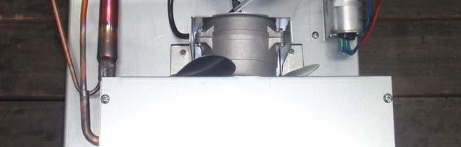
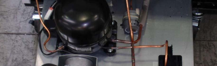
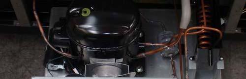
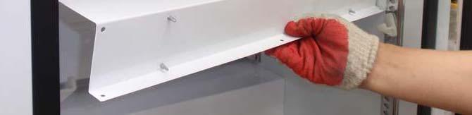
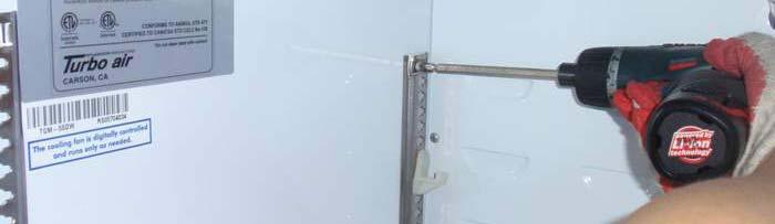
73 7. REPLACEMENT OF MAIN COMPONENTS 7-1. TGM-5SD*, TGM-7SD*, TGF-5SD* BACK COVER PARTS - COMPRESSOR, CONDENSER, CONDENSER FAN MOTOR. SMPS - DEFROST TIMER(FREEZER) A. Remove the six screws, and pull out the Back Cover. B. Remove the six screws and Replace the Main Components.


74 REPLACEMENT OF MAIN COMPONENTS DOOR PARTS A. Remove the Four screws on the top hinge. B. Disconnect the two wires and Remove the four screws on the bottom hinge. => There is no wire heater in the Refrigerator(TGM-5SD*, TGM-7SD*) C. Replace the Door ASSY.
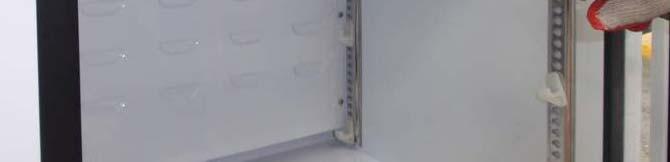
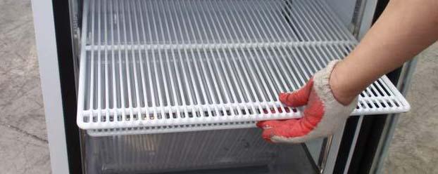

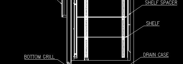
75 REPLACEMENT OF MAIN COMPONENTS REFRIGERATION COMPARTMENT PARTS. A. Remove the eight screws and pull out the Evaporator Front Cover. - Replace the thermostat and LED. B. Pull out and Remove the shelves. C. Remove the screws on the shelf standards.


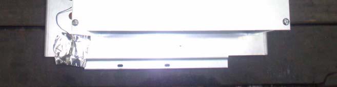
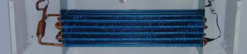
76 REPLACEMENT OF MAIN COMPONENTS D. Remove the screws and pull out the back cover. D. Remove the screws and pull out the Evaporator bottom cover. E. Replace the main components. TGM-5SD*, TGM-7SD* -Replace the Evaporator and Evaporator fan motor. TGF-5SD* - Replace the Evaporator and Evaporator fan motor and Defrost Heater.


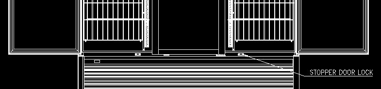
77 REPLACEMENT OF MAIN COMPONENTS DOOR SWITCH. A. Remove the four screws and pull out the Door Switch Assy. B. Replace the Door Switch.


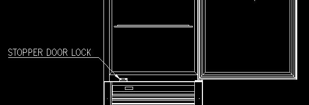
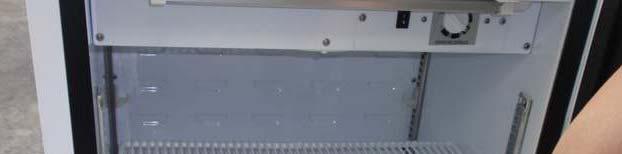
78 REPLACEMENT OF MAIN COMPONENTS 7-2. TGM-10SD*, TGM-12SD*, TGF-10SD* BOTTOM GRILLE PARTS - MAIN PCB, SMPS, POWER RELAY - DISPLAY PCB, LAMP SWITCH, POWER SWITCH - COMPRESSOR, CONDENSER, CONDENSER FAN MOTOR. A. Lift and pull out the Bottom Grill. B. Remove the two screws and Replace the Display PCB and Switch. ( Power Switch, Lamp Switch)


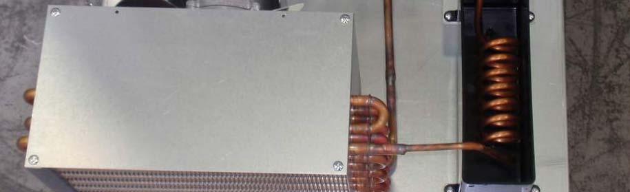
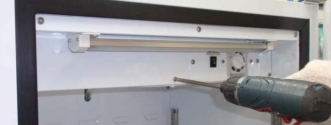
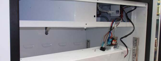
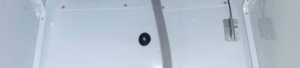
79 REPLACEMENT OF MAIN COMPONENTS C. Remove the Electrical Box Cover. -. Remove the four screws and pull out -. Remove the four screws and pull out the Back Grill Assy. the Back Grill Assy. -. Remove the two screws and pull out the Switch Box ASSY. -. Replace the Main PCB & SMPS & Power Relay d. Replace the speaker. - Speaker is on the left side wall.


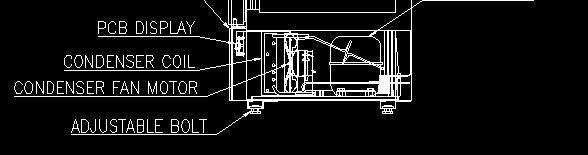
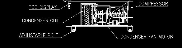
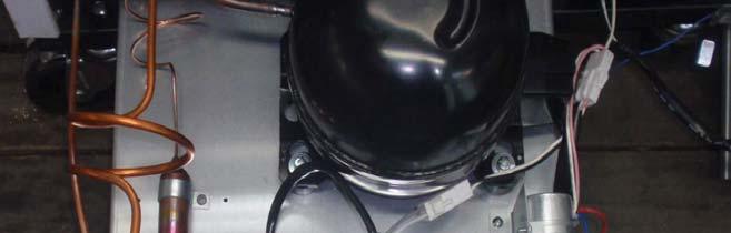
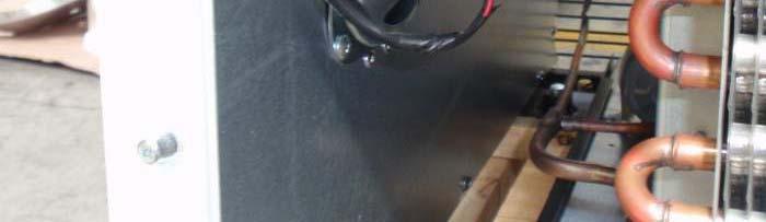
80 E. Replace the Condensing Unit REPLACEMENT OF MAIN COMPONENTS -. Remove the two screws and pull out the Condensing Unit. -. Replace the Compressor & Condenser & Condenser Fan Motor.


81 REPLACEMENT OF MAIN COMPONENTS DOOR PARTS A. Remove the Four screws on the top hinge. B. Disconnect the two wires and Remove the four screws on the bottom hinge. => There is no wire heater in the Refrigerator(TGM-5SD*, TGM-7SD*) C. Replace the Door ASSY.


82 REPLACEMENT OF MAIN COMPONENTS REFRIGERATION COMPARTMENT PARTS. A. Remove the eight screws and pull out the Evaporator Front Cover. - Replace the LED. B. Pull out and Remove the shelves. C. Remove the screws on the shelf standards.


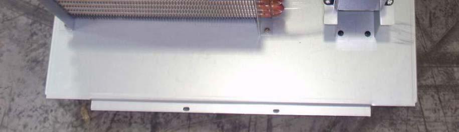
83 REPLACEMENT OF MAIN COMPONENTS D. Remove the screws and pull out the back cover. D. Remove the screws and pull out the Evaporator bottom cover. E. Replace the min components. TGM-10SD*, TGM-12SD* -Replace the Evaporator and Evaporator fan motor and Sensors. TGF-10SD* - Replace the Evaporator and Evaporator fan motor and Defrost Heater and sensors.


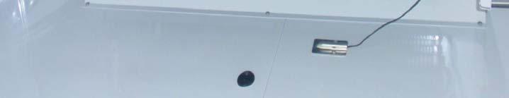
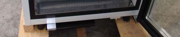
84 REPLACEMENT OF MAIN COMPONENTS DOOR SWITCH. A. Pull out the Door Switch. B. Replace the Door Switch.


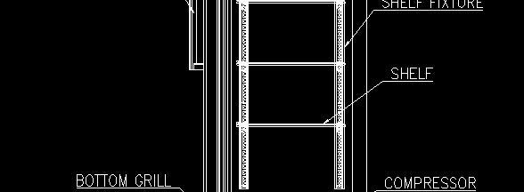
85 REPLACEMENT OF MAIN COMPONENTS 7-3. TGM-15SD*, TGM-20SD*, TGM-23SD*, TGF-15SD*, TGF-23SD* BOTTOM GRILLE PARTS - MAIN PCB, SMPS, POWER RELAY - DISPLAY PCB, LAMP SWITCH, POWER SWITCH - COMPRESSOR, CONDENSER, CONDENSER FAN MOTOR. A. Lift and pull out the Bottom Grill B. Remove the two screws and Replace the Display PCB and Switch. ( Power Switch, Lamp Switch)


86 C. Remove the Electrical l Box Cover. REPLACEMENT OF MAIN COMPONENTS -. Remove the two screws and pull out the Switch Box ASSY. -. Replace the Main PCB & SMPS & Power Relay


87 D. Replace the Condensing Unit REPLACEMENT OF MAIN COMPONENTS -. Remove the two screws and pull out the Condensing Unit. -. Replace the Compressor & Condenser & Condenser Fan Motor.


88 REPLACEMENT OF MAIN COMPONENTS SIGN PANEL PARTS - SIGN PANEL ASSY, LIGHT GUIDE PANEL -SPEAKER - DOOR SWITCH A. Remove the four screws and lift the Sign Panel Assy. B. Replace the Light Guide Panel & Speaker & Door Switch.


89 REPLACEMENT OF MAIN COMPONENTS DOOR PARTS A. Remove the three screws on the top hinge. B. Disconnect the two wires and Remove the four screws on the bottom hinge. => There is no wire heater in the SD Refrigerator(TGM-15SD*, TGM-23SD*) C. Replace the Door ASSY.


 and")


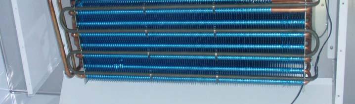
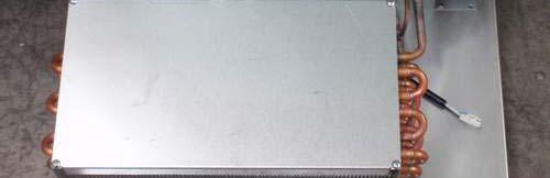
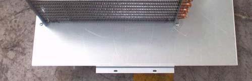
90 REPLACEMENT OF MAIN COMPONENTS REFRIGERATION COMPARTMENT PARTS. A. Remove the screws on the Duct(A) and (B) B. Replace the Evaporator & Evaporator Fan Motor & Sensors & Sheath Heater.


91 REPLACEMENT OF MAIN COMPONENTS LED LAMP A. Remove the two screws on the LED COVER. B. Disconnect the two wires and Replace the LED LAMP.


92 REPLACEMENT OF MAIN COMPONENTS 7-4. TGM-35SD*, TGM-47SD*, TGM-72SD*, TGF-35SD*, TGF-47SD*, TGF-72SD* BOTTOM GRILLE PARTS - MAIN PCB, SMPS, POWER RELAY - DISPLAY PCB, LAMP SWITCH, POWER SWITCH - COMPRESSOR, CONDENSER, CONDENSER FAN MOTOR. A. Lift and pull out the Bottom Grill B. Remove the two screws and Replace the Display PCB and Switch. ( Power Switch, Lamp Switch)


93 REPLACEMENT OF MAIN COMPONENTS SIGN PANEL PARTS - SIGN PANEL ASSY, LIGHT GUIDE PANEL - SPEAKER, DOOR SWITCH - SMPS(for LED in the interior part) A. Remove the four screws and lift the Sign Panel Assy. B. Replace the Light Guide Panel & Speaker & Door Switch & SMPS


94 REPLACEMENT OF MAIN COMPONENTS DOOR PARTS A. Remove the three screws on the top hinge. B. Disconnect the two wires and Remove the four screws on the bottom hinge. => There is no wire heater in the SD Refrigerator(TGM-47SD*, TGM-72SD*) C. Replace the Door ASSY.


95 REPLACEMENT OF MAIN COMPONENTS REFRIGERATION COMPARTMENT PARTS. A. Remove the screws on the Duct(A) and (B) B. Replace the Evaporator & Evaporator Fan Motor & Sensors & Sheath Heater.


96 REPLACEMENT OF MAIN COMPONENTS LED LAMP A. Disconnect the two wires the rear of the Sign Panel. B. Replace the LED LAMP.
TGF-9F TGF-13F TGF-23F TGF-49F TGF-72F
 TGF-9F TGF-3F TGF-23F TGF-49F TGF-72F TABLE OF CONTENTS. FEATURE CHART 2. PART DETAILS 3. WIRING DIAGRAM 4. MAIN COMPONENTS 5. ELECTRONIC CONTROLLER INSTRUCTION 6. PARTS LIST 7. REPLACEMENT OF MAIN COMPONENTS
Turbo air. Horizontal Bottle Coolers Model No. : TBC-24SD/SB TBC-36SD/SB. Commercial Refrigerator Service Manual TBC-95SD/SB TBC-65SD/SB TBC-80SD/SB
 REFRIGERATOR MANUFACTURER Turbo air Commercial Refrigerator Service Manual Horizontal Bottle Coolers Model No. : TBC-24SD/SB TBC-36SD/SB TBC-50SD/SB TBC-65SD/SB TBC-80SD/SB TBC-95SD/SB TABLE OF CONTENTS
Commercial Refrigerator & Freezer Service Manual
 Commercial Refrigerator & Freezer Service Manual Sandwich Salad Unit Under counter Refrigerator & Freezer Model No.: TUR-28SD TUR-48SD TST-28SD TST-48SD TUF-28SD TUF-48SD TABLE OF CONTENTS. FEATURE CHART
TECHNICAL MANUAL F49-S, F49-SH F72-S, F72-SH R49-S, R49-SH, R49-G R72-S, R72-SH, R72-G - 1 -
 TECHNICAL MANUAL FREEZER : F23-S, F23-SH F49-S, F49-SH F72-S, F72-SH REFRIGERATOR : R23-S, R23-SH, R23-G R49-S, R49-SH, R49-G R72-S, R72-SH, R72-G MERCHANDISERS : GR26H, GR48S, GR72H - 1 - A. GENERAL 1.
Commercial Refrigerator Service Manual
 Commercial Refrigerator Service Manual Horizontal Bottle Coolers Model No.: TBC-50SD TBC-95SD Commercial Refrigerator Service Manual Horizontal Bottle Coolers Model No.: TBC-50SD TBC-95SD TABLE OF CONTENTS
Display Cases Deli Cases Service Manual
 Turbo Air Speed up the Pace of Innovation CAUTION! PLEASE KEEP POWER SWITCH ON BEFORE OPERATING THIS EQUIPMENT Display Cases Deli Cases Service Manual Please read this manual completely before attempting
Commercial Upright Bottom Mount Refrigerator & Freezer Service Manual
 Commercial Upright Bottom Mount Refrigerator & Freezer Service Manual - 1 - TABLE OF CONTENS 1. ASSEMBLY 4~15 2. PARTS 16~36 3. WIRING DIAGRAM 37~39 4. PART DETAILS 40~44 5. MAIN COMPONENTS 45~61 6. ELECTRONIC
Mega Top Sandwich Prep Table Manual
 Mega Top Sandwich Prep Table Manual Model SUSS-27-12 1. Technical Specifications Amp 115V 3.4A Connection 15 amp plug Name R134a Refrigerant Q'ty (oz) 3.2 Q'ty (gram) 90 HP 1/5 HP Compressor Samsung SD162C-L1U2
Commercial Refrigerator Service Manual
 Commercial Refrigerator Service Manual Undercounter Freezer Model No.: TUF-28SD TUF-48SD TABLE OF CONTENTS 1.FEATURE CHART 1-1.FRONT VIEW 1-2.SIDE VIEW 2.WIRING DIAGRAMS 2-1.TUF-28SD 2-2.TUF-48SD 3.PART
Commercial Refrigerator & Freezer Service Manual Please read this manual completely before attempting to install or operate this equipment!
 Turbo Air Speed up the Pace of Innovation CAUTION! PLEASE KEEP POWER SWITCH ON BEFORE OPERATING THIS EQUIPMENT Commercial Refrigerator & Freezer Service Manual Please read this manual completely before
Commercial Refrigerator Service Manual. Under Counter Prep Table Model : MUR-28 MUR-48 MUR-60 MUR-72
 Commercial Refrigerator Service Manual Under Counter Prep Table Model : MUR-28 MUR-48 MUR-60 MUR-72 TABLE OF CONTENTS. EXPLODED VIEW -. MUR-28SD EXPLODED VIEW -2. MUR-48SD EXPLODED VIEW -3. MUR-60SD EXPLODED
Commercial Refrigerator Service Manual
 Commercial Refrigerator Service Manual Sandwich Prep Table Model : MST-28 MST-48 MST-60 MST-72 TABLE OF CONTENTS. EXPLODED VIEW -.MST-28 EXPLODED VIEW -.MST-48 EXPLODED VIEW -.MST-60 EXPLODED VIEW -.MST-72
Service Manual For MCR27S, MCR48S, MCR72S, MCR27U, MCR48U, MCR72U MCF27U, MCF48U, MCF72U. Visit us on the web at
 Service Manual For MCR27S, MCR48S, MCR72S, MCR27U, MCR48U, MCR72U MCF27U, MCF48U, MCF72U Visit us on the web at www.asburyfoodservice.com CONTENTS 1. SPECIFICATIONS ---------------------------------------------2
Commercial Pizza Prep Tables Service Manual
 Turbo Air Speed up the Pace of Innovation CAUTION! PLEASE KEEP POWER SWITCH ON BEFORE OPERATING THIS EQUIPMENT Commercial Pizza Prep Tables Service Manual Please read this manual completely before attempting
Commercial Refrigerator & Freezer Service Manual. Solid Door J series Model JRF-19
 Commercial Refrigerator & Freezer Service Manual Solid Door J series Model JRF-19 TABLE OF CONTENTS 1.FEATURE CHART 1-1. FRONT VIEW/PLAN VIEW:JRF-19 2.WIRING DIAGRAM 3.PART DETAIL 3-1.TOP GRILLE 3-2.REFRIGERATION
Headquarter: 1250 Victoria street CARSON, CA & Canada Toll Free TEL: (562) FAX: (562)
 FAX: (562)") Headquarter: 250 Victoria street CARSON, CA 90746 & Canada Toll Free 800-627-0032 TEL: (562)98-023 FAX: (562)98-024 www.turboairinc.com 02000 Commercial Refrigerator & Freezer Service Manual Model No.:
Headquarter: 250 Victoria street CARSON, CA 90746 & Canada Toll Free 800-627-0032 TEL: (562)98-023 FAX: (562)98-024 www.turboairinc.com 02000 Commercial Refrigerator & Freezer Service Manual Model No.:
FN-510DW. FN-651NW same as FN510DW FR-650NT.. FN-650NT.. FR-650NW.. FN-650NW.. FR-651NT.. FN-651NT.. FN-651NW FR-651NW.. FN-510DW
 FN-50DW FR-650NT.. FN-650NT.. FR-650NW.. FN-650NW.. FR-65NT.. FN-65NT.. FN-50DW FN-65NW FR-65NW.. FN-65NW same as FN50DW Sep. 20. C O N T E N T S WARNINGS AND PRECAUTIONS FOR SAFETY --------------------------------
Undercounter Freezer Service Manual
 Turbo Air Speed up the Pace of Innovation CAUTION! PLEASE KEEP POWER SWITCH ON BEFORE OPERATING THIS EQUIPMENT Undercounter Freezer Service Manual Please read this manual completely before attempting to
Service Manual For BAPT1, BAPT2, BAPT3 BAUR1, BAUR2, BAUR3, BAUF1, BAUF2
 Service Manual For BAPT1, BAPT2, BAPT3 BAUR1, BAUR2, BAUR3, BAUF1, BAUF2 BAPT(Prep Table) BAUR / BAUF (Undercounter Ref / Frz) Visit us on the web at www.blueairinc.com CONTENTS 1. SPECIFICATIONS '------------------------------------------2
RC-54CA RO-50CA RC-54HA RO-50HA. SPLIT TYPE AIR CONDITIONER CASSETTE TYPE (50Hz) Indoor unit Outdoor unit
 Indoor unit Outdoor unit") SPLIT TYPE AIR CONDITIONER CASSETTE TYPE (50Hz) Indoor unit Outdoor unit RCW-54CB RO-50CA RC-54CA RO-50CA RC-54HA RO-50HA CONTENTS SPECIFICATIONS OUTLINE AND DIMENTIONS CIRCUIT DIAGRAM REFRIGERANT SYSTEM
SPLIT TYPE AIR CONDITIONER CASSETTE TYPE (50Hz) Indoor unit Outdoor unit RCW-54CB RO-50CA RC-54CA RO-50CA RC-54HA RO-50HA CONTENTS SPECIFICATIONS OUTLINE AND DIMENTIONS CIRCUIT DIAGRAM REFRIGERANT SYSTEM
Repair Parts List REFRIGERATOR MODEL NUMBER ARB190ZCW MANUFACTURING NUMBER PARB190ZCW0
 REFRIGERATOR Repair Parts List MODEL NUMBER ARB190ZCW MANUFACTURING NUMBER PARB190ZCW0 When requesting service or ordering parts, always provide the following information: - Product Type - Part Number
Repair Parts List REFRIGERATOR MODEL NUMBER LTF2112ARB. When requesting service or ordering parts, always provide the following information:
 Repair Parts List REFRIGERATOR MODEL NUMBER LTF2112ARB When requesting service or ordering parts, always provide the following information: - Product Type - Part Number - Model Number - Part Description
COMMERCIAL REFRIGERATOR & FREEZER SERVICE MANUAL (SCL/SCLM)
") COMMERCIAL REFRIGERATOR & FREEZER SERVICE MANUAL (SCL/SCLM) MODEL: SCL1 SCL2 SCL2-36 SCL2-60 SCL3 SCLM1 SCLM2 SCLM2-36 SCLM2-60 SCLM3 TABLE OF CONTENTS 1. EXPLODED VIEW AND PARTS LIST... 3 1.1 SCL1 & SCLM1...
COMMERCIAL REFRIGERATOR & FREEZER SERVICE MANUAL (SCL/SCLM) MODEL: SCL1 SCL2 SCL2-36 SCL2-60 SCL3 SCLM1 SCLM2 SCLM2-36 SCLM2-60 SCLM3 TABLE OF CONTENTS 1. EXPLODED VIEW AND PARTS LIST... 3 1.1 SCL1 & SCLM1...
CHEF BASE CABINETS Installation, Operation and Maintenance Instructions
 CHEF BASE CABINETS Installation, Operation and Maintenance Instructions INSPECTION When the equipment is received, all items should be carefully checked against the Bill of Lading to ensure all crates
Spare Parts Catalogue MV1006
 Spare Parts Catalogue MV1006 1 - UNIT PANELS - AIR COOLED 2 - UNIT PANELS - WATER COOLED 3 - REFRIGERANT SYSTEM - AIR COOLED - UP TO S.N. 00462 4 - REFRIGERANT SYSTEM - AIR COOLED - FROM S.N. 00463 TO
CABINET PARTS For Models: KBRS22KGWH0, KBRS22KGAL0, KBRS22KGBL0 (White) (Almond) (Black)
 (Almond) (Black)") CABINET PARTS REFRIGERATOR 8-99 Litho In U.S.A. (mdg) 1 Part No. Rev. B CABINET PARTS 1 Cabinet (Not a Service Part) 3 Plug, Button (3) 4344191 White 4344189 Almond 4344190 Black 4 Plug, Button (3) 4344535
CABINET PARTS REFRIGERATOR 8-99 Litho In U.S.A. (mdg) 1 Part No. Rev. B CABINET PARTS 1 Cabinet (Not a Service Part) 3 Plug, Button (3) 4344191 White 4344189 Almond 4344190 Black 4 Plug, Button (3) 4344535
CATALOG OF REPLACEMENT PARTS
 CATALOG OF REPLACEMENT PARTS CU48 & CU60 SERIES COMPACT UNDERCOUNTER FOOD STORAGE CABINETS (Kansas City) Machines Starting With Serial Number 32XXXXXXX CU48 REFRIGERATOR CUG48 FREEZER CUS48 REFRIGERATOR
Image Key Part Number Description Substitution Qty.
 Model Number: BOM/Serial #: Graphic Title: XRSR465BW PXRSR465BW0 SUPPLEMENTAL INFORMATION Image Key Part Number Description Substitution Qty. 1 1 67002385 HARNESS-CONTROL 1 1 1 67002384 HARNESS, ICE MAKER
INSTALLATION and OPERATION INSTRUCTIONS
 INSTALLATION and OPERATION INSTRUCTIONS SINGLE DOOR freezer MODEL NOS. FN FS Finished Stainless Steel Top Non-Finished Top FS FN IMPORTANT INFORMATION This manual has been prepared to assist you in the
UML 1- TS UML 2- BS UML 3- BS
 2-S-444 Compressor 3/4 hp 115-Volt R-404A 1 1 Starts S/N 95C01577 & Above 2-S-445 Compressor 1 hp 208/230-Volt R-404A 1 1 Starts S/N 95B01475 & Above 2-S-446 Compresor 1-1/2 hp 208/230-Volt R-404A 1 1
CU0415, CU0715 and CU0920 Service Parts
 CU0, CU0 and CU00 Service Parts This is the illustrated parts list for the CU0, CU0 and CU00. The CUR0, CUR0 and CUR00 are - (0-0/0/) versions of the matching models. There are voltages, /0/, 0-0/0/ and
SERVICE Manual FREE JOINT MULTI AIR CONDITIONER
 FREE JOINT MULTI AIR CONDITIONER INDOOR UNIT MH020FPEA MH023FPEA MH026FPEA MH035FPEA MH052FPEA MH8VP2-09 MH9VP2-07 MH9VP2-2 MH026FKEA MH035FKEA MH052FDEA OUTDOOR UNIT MH8VP2X MH9VP2X MH052FXEA2 MH068FXEA4
Repair Parts List REFRIGERATOR MODEL NUMBER ARB1917CSR MANUFACTURING NUMBER PARB1917CS1
 REFRIGERATOR Repair Parts List MODEL NUMBER ARB1917CSR MANUFACTURING NUMBER PARB1917CS1 When requesting service or ordering parts, always provide the following information: - Product Type - Part Number
GAS COMPONENTS ELECTRIC COMPONENTS WATER TECHNOLOGY MECHANICAL COMPONENTS TOOLS. Spare parts suitable for WILLIAMS
 GAS COMPONENTS ELECTRIC COMPONENTS WATER TECHNOLOGY MECHANICAL COMPONENTS TOOLS Spare parts suitable for WILLIAMS WILLIAMS heating elements/thermostats/probes/electronics heating elements heating elements
Repair Parts List REFRIGERATOR MODEL NUMBER JCB2059GES MANUFACTURING NUMBER PJCB2059GS0
 REFRIGERATOR Repair Parts List MODEL NUMBER JCB2059GES MANUFACTURING NUMBER PJCB2059GS0 When requesting service or ordering parts, always provide the following information: - Product Type - Part Number
Repair Parts List REFRIGERATOR MODEL NUMBER ABB1921DEW. When requesting service or ordering parts, always provide the following information:
 Repair Parts List REFRIGERATOR MODEL NUMBER ABB1921DEW When requesting service or ordering parts, always provide the following information: - Product Type - Part Number - Model Number - Part Description
Undercounter Refrigerator Service Manual
 Turbo Air Speed up the Pace of Innovation CAUTION! PLEASE KEEP POWER SWITCH ON BEFORE OPERATING THIS EQUIPMENT Undercounter Refrigerator Service Manual Please read this manual completely before attempting
EXPLODED VIEWS & PARTS LISTS
 542 DOOR VIEW Ref. Part No. Description Ref. Part No. Description 1 6200720 Screw, #8-18 x 1/2 PH Truss HD 2 420040 Standard Handle End Cap Replacement Components 4200700 Extended Handle End Cap Replacement
Repair Parts List REFRIGERATOR MODEL NUMBER MBB1952HEW. When requesting service or ordering parts, always provide the following information:
 Repair Parts List REFRIGERATOR MODEL NUMBER MBB1952HEW When requesting service or ordering parts, always provide the following information: - Product Type - Part Number - Model Number - Part Description
Salad Table Refrigerator & Freezer Service Manual
 Turbo Air Speed up the Pace of Innovation CAUTION! PLEASE KEEP POWER SWITCH ON BEFORE OPERATING THIS EQUIPMENT Salad Table Refrigerator & Freezer Service Manual Please read this manual completely before
Repair Parts List REFRIGERATOR MODEL NUMBER GC20B8C3EB. When requesting service or ordering parts, always provide the following information:
 Repair Parts List REFRIGERATOR MODEL NUMBER GC20B8C3EB When requesting service or ordering parts, always provide the following information: - Product Type - Part Number - Model Number - Part Description
Installation and Operation Guide For MCF-49FD, MCF-23FD MCR-49FD, MCR-23FD
 Installation and Operation Guide For MCF-49FD, MCF-23FD MCR-49FD, MCR-23FD CONTENTS 1. SPECIFICATIONS 2. SERIAL NUMBER 3. INSTALLATION 4. CLEANING 5. CAUTION 6. BASIC OPERATION 6-1. REFRIGERATOR 6-2. FREEZER
CASSETTE type INVERTER MULTI AIR CONDITIONER. Models AUY12LBAB AUY14LBAB AOY18LMAK2
 INVERTER MULTI AIR CONDITIONER CASSETTE type Models Indoor unit AUY12LBAB AUY14LBAB Outdoor unit AOY18LMAK2 CONTENTS SPECIFICATIONS..................... 1 OUTLINE AND DIMENSIONS........... 2 REFRIGERANT
CAREL IR33+ CONTROLLER
 CAREL IR33+ CONTROLLER Programming Instructions The Carel IR33+ controller has a two-level menu system for programming the operation of the case; Level 1 and Level 2 program settings. Unlike IR33, the
ELECTROLUX ELECTRONICALLY CONTROLLED COMPACT SIDE BY SIDE REFRIGERATORS
 ELECTROLUX HOME PRODUCTS PTY LTD ABN 51 004 762 341 Issue: 1 Technical Publication Nº XRE180 Date: 12/10 WEB SITE ADDRESS: www.partnship.com.au ELECTROLUX ELECTRONICALLY CONTROLLED COMPACT SIDE BY SIDE
WESTINGHOUSE ELECTRONICALLY CONTROLLED A SERIES COMPACT SIDE BY SIDE REFRIGERATORS
 ELECTROLUX HOME PRODUCTS PTY LTD ABN 51 004 762 341 Issue: 1 Technical Publication Nº RE129 Book C27 Date: 08/05 WEB SITE ADDRESS: www.partnship.com.au WESTINGHOUSE ELECTRONICALLY CONTROLLED A SERIES COMPACT
4. ALIGNMENT AND ADJUSTMENTS
 4-1) Forced Operation Function (Pull-down / Refrigerator Defrost / Refrigerator. Freezer-Defrost / Cancellation) 28 4-2) Sound function 29 4-3) Exhibition Function 29 4-4) Self-Diagnostics Function29 4-5)
CABINET PARTS For Model: JS42CXFXDB00 (Etched Aluminum)
") CABINET PARTS 42" BUILT IN REFRIGERATOR 1 08 Litho In U.S.A. (mat) 1 Part No. Rev. A CABINET PARTS 1 Literature Parts W10151251 Use & Care Guide W10164079 Energy Guide W10159831 Service & Wiring Sheet
CABINET PARTS 42" BUILT IN REFRIGERATOR 1 08 Litho In U.S.A. (mat) 1 Part No. Rev. A CABINET PARTS 1 Literature Parts W10151251 Use & Care Guide W10164079 Energy Guide W10159831 Service & Wiring Sheet
REF5-BB Undercounter Blood Bank Refrigerator
 REF5-BB Undercounter Blood Bank Refrigerator Order parts online www.follettice.com Installation, Operation and Service Manual Following installation, please forward this manual to the appropriate operations
ELECTROLUX ELECTRONICALLY CONTROLLED COMPACT SIDE BY SIDE REFRIGERATOR
 ELECTROLUX HOME PRODUCTS PTY LTD ABN 51 004 762 341 Issue: 1 Technical Publication Nº XRE33 Date: 7/06 WEB SITE ADDRESS: www.partnship.com.au ELECTROLUX ELECTRONICALLY CONTROLLED COMPACT SIDE BY SIDE REFRIGERATOR
MSD2652KES COMPRESSOR
 MSD2652KES CABINET 1 67003576 50 ELBOW, FILL TUBE 2 M0114003 50 CLIP, SPEED 3 67003360 50 TUBE, PLASTIC 4 A3223101 50 INSERT, PLASTIC TUBE 5 M0104106 50 CLIP 6 67006506 50 CORD, POWER 7 67006433 50 SCREW
Electrical Problems. Fuse(s) blow or circuit breaker trips. Does the unit use circuit breakers or fuses? Replace with correct fuse(s)
 blow or circuit breaker trips. Does the unit use circuit breakers or fuses? Replace with correct fuse(s)") Electrical Problems Fuse(s) blow or circuit breaker trips Does the unit use circuit breakers or fuses? Fuse(s) Circuit breakers Are the fuses dual element time delay? Is the circuit breaker HACR rated?
Electrical Problems Fuse(s) blow or circuit breaker trips Does the unit use circuit breakers or fuses? Fuse(s) Circuit breakers Are the fuses dual element time delay? Is the circuit breaker HACR rated?
Undercounter Glass Door Refrigerator Service Manual
 Turbo Air Speed up the Pace of Innovation CAUTION! PLEASE KEEP POWER SWITCH ON BEFORE OPERATING THIS EQUIPMENT Undercounter Glass Door Refrigerator Service Manual Please read this manual completely before
CABINET PARTS For Models: W8RXNGMWB02, W8RXNGMWS02, W8RXNGMWL02 (Black) (Stainless Steel) (Satina)
 (Stainless Steel) (Satina)") CABINET PARTS REFRIGERATOR 1 12 Litho In U.S.A. (mlg)(bay) 1 Part No. Rev.A CABINET PARTS 1 Literature Parts W10402929 Service & Wiring Sheet 2316016 Use & Care Guide 628370 Modular Icemaker Service Sheet
CABINET PARTS REFRIGERATOR 1 12 Litho In U.S.A. (mlg)(bay) 1 Part No. Rev.A CABINET PARTS 1 Literature Parts W10402929 Service & Wiring Sheet 2316016 Use & Care Guide 628370 Modular Icemaker Service Sheet
CABINET PARTS For Model: EF48DBSS (Stainless Steel)
") CABINET PARTS 48" BUILT IN REFRIGERATOR 08 19-13 1 CABINET PARTS 1 Literature Parts W10159566 Use & Care Guide W10165112 Energy Guide W10180103 Service & Wiring Sheet 2306424 Icemaker and Ingredient Care
CABINET PARTS 48" BUILT IN REFRIGERATOR 08 19-13 1 CABINET PARTS 1 Literature Parts W10159566 Use & Care Guide W10165112 Energy Guide W10180103 Service & Wiring Sheet 2306424 Icemaker and Ingredient Care
Commercial Refigerator Chef Bases Service Manual Please read this manual completely before attempting to install or operate this equipment!
 Turbo Air Speed up the Pace of Innovation CAUTION! PLEASE KEEP POWER SWITCH ON BEFORE OPERATING THIS EQUIPMENT Commercial Refigerator Chef Bases Service Manual Please read this manual completely before
BEVERAGE-AIR PARTS MANUAL FOR CFG & CRG
 BEVERAGE-AIR PARTS MANUAL FOR CFG & CRG ALL PURPOSE COLD R GLASS DOOR REACH IN FREEZERS & REFRIGERATORS CFG12/24/36/48/74 115V/60HZ 208-230V/60HZ PM11 01/31/01 PART PAGE NUMBER PART PAGE NUMBER ACCUMULATORS
Commercial Series. Power switch & Nameplate location: NAMEPLATE: Single and Dual Section
 COMMERCIAL SERIES Commercial Series Commercial Series Power switch & Nameplate location: NAMEPLATE: Single and Dual Section Must reach over behind Front Panel to access: Single and Dual Section Commercial
ELECTROLUX ELECTRONICALLY CONTROLLED COMPACT SIDE BY SIDE REFRIGERATOR
 ELECTROLUX HOME PRODUCTS PTY LTD ABN 51 004 762 341 Issue: 1 Technical Publication Nº XRE119 Date: 7/06 WEB SITE ADDRESS: www.partnship.com.au ELECTROLUX ELECTRONICALLY CONTROLLED COMPACT SIDE BY SIDE
CME1856W Service Parts
 This parts list contains the part numbers and description of the replacement parts available for this model. To avoid costly and time consuming errors, double check the model and voltage before ordering
Installation and Operation Guide For
 Installation and Operation Guide For S23R, S49R, S23F, S49F S23RG, S49RG Refrigerator S23R S49R Freezer S23F S49F Refrigerator S23RG S49RG CONTENTS 1. SPECIFICATIONS 2. SERIAL
CME1856W Service Parts
 This parts list contains the part numbers and description of the replacement parts available for this model. To avoid costly and time consuming errors, double check the model and voltage before ordering
Headquarter: 1250 Victoria street CARSON, CA & Canada Toll Free TEL: FAX:
 Headquarter: 250 Victoria street CARSON, CA 90746 & Canada Toll Free 800-627-0032 TEL: 30-900-000 FAX: 30-900-077 www.turboairinc.com 02000 Commercial Refrigerator & Freezer Service Manual Model No.: TGM-69R
Refrigerator Compartment Assembly
 Refrigerator Compartment Assembly REFRIGERATOR COMPARTMENT ASSEMBLY ITEM PART NUMBER PART DESCRIPTION QTY 1 PM910236 Glass Shelf 2 G5099426 Shelf and Slide Assembly 3 G32910068 DRAWER DELI & RAIL ASM SXS
TABLE OF CONTENTS REFRIGERATOR-FREEZER. Model No. NR-BN34FX1 Model No. NR-BN34FW1
 Order Number GORR1405001CE REFRIGERATOR-FREEZER Model No. NR-BN34FX1 Model No. NR-BN34FW1 Product-Color X:Stainless W:White Destination E(Europe Continental) B(U.K.) TABLE OF CONTENTS PAGE 1 Safety Precautions-----------------------------------------------
Repair Parts List REFRIGERATOR MODEL NUMBER MBR1956HES. When requesting service or ordering parts, always provide the following information:
 Repair Parts List REFRIGERATOR MODEL NUMBER MBR1956HES When requesting service or ordering parts, always provide the following information: - Product Type - Part Number - Model Number - Part Description
DIRECT DRAW BEER COOLERS Installation, Operation and Maintenance Instructions
 DIRECT DRAW BEER COOLERS Installation, Operation and Maintenance Instructions INSPECTION When the equipment is received, all items should be carefully checked against the Bill of Lading to ensure all crates
DUCT type. Большая библиотека технической документации каталоги, инструкции, сервисные мануалы, схемы.
 SPLIT TYPE AIR CONDITIONER (50Hz) DUCT type Models Indoor unit Outdoor unit RD-25CA RD-25HA RD-30CA RD-30HA RO-25CA RO-25HA RO-30CA RO-30HA C O N T E N T S SPECIFICATIONS.............................................
EXPLODED VIEWS & PARTS LISTS
 561 DOOR VIEW Ref. Part No. Description Ref. Part No. Description 1 6200720 Screw, #8-18 x 1/2 PH Truss HD 2 420040 Standard Handle End Cap Replacement Components 4200700 Extended Handle End Cap Replacement
CABINET PARTS For Model: KSSS48QJX00 (Stainless Steel)
") CABINET PARTS 48" BUILT IN REFRIGERATOR 10 02 Litho In U.S.A. (mek) 1 Part No. 1 LITERATURE PARTS LIT2209249 Use & Care Guide LIT2006651 Energy Label LIT2006748 Service & Wiring Sheet LIT628370 Modular
CABINET PARTS 48" BUILT IN REFRIGERATOR 10 02 Litho In U.S.A. (mek) 1 Part No. 1 LITERATURE PARTS LIT2209249 Use & Care Guide LIT2006651 Energy Label LIT2006748 Service & Wiring Sheet LIT628370 Modular
SPLIT TYPE ROOM AIR CONDITIONER CEILING TYPE (60Hz)
") SPLIT TYPE ROOM AIR CONDITIONER CEILING TYPE (60Hz) Indoor unit MS6YF Outdoor unit MR6YF CONTENTS SPECIFICATIONS... OUTLINE AND DIMENSIONS... REFRIGERANT SYSTEM DIAGRAM.... CIRCUIT DIAGRAM... INDOOR PCB
SPLIT TYPE ROOM AIR CONDITIONER CEILING TYPE (60Hz) Indoor unit MS6YF Outdoor unit MR6YF CONTENTS SPECIFICATIONS... OUTLINE AND DIMENSIONS... REFRIGERANT SYSTEM DIAGRAM.... CIRCUIT DIAGRAM... INDOOR PCB
Fast Track Troubleshooting
 Fast Track Troubleshooting Model: RH22** Bulletins: IMPORTANT SAFETY NOTICE For Technicians Only This service data sheet is intended for use by persons having electrical, electronic, and mechanical experience
CASSETTE type INVERTER MULTI AIR CONDITIONER
 INVERTER MULTI AIR CONDITIONER CASSETTE type Models Indoor unit AUY12LBAB AUY14LBAB Outdoor unit AOY18LMAK2 CONTENTS SPECIFICATIONS..................... 1 OUTLINE AND DIMENSIONS........... 2 REFRIGERANT
WALL MOUNTED type SPLIT TYPE ROOM AIR CONDITIONER CONTENTS. Models
 SPLIT TYPE ROOM AIR CONDITIONER WALL MOUNTED type Models Indoor unit ASY9USCCW ASY9USCCW ASY12USCCW Outdoor unit AOY9USCC AOY9UFCC AOY12USCC CONTENTS SPECIFICATIONS................................... 1
WHIRLPOOL REFRIGERADOR GS2SHGXLQ01
 CABINET, LITERATURE 1 CABINET, LITERATURE 1 LIT2220425 LITERATURE PARTS (Energy Label) 1 LIT2220699 LITERATURE PARTS (Owner`s Manual) 1 LIT2255381 LITERATURE PARTS (Service & Wiring Sheet) 1 LIT628370
Glass Door Merchandiser. Model RM-49
 Glass Door Merchandiser Model Number: Issued: 02-22-2017 Revised: 02-22-2017 2 TABLE OF CONTENTS UNIT FEATURES 4 Page CROSS SECTION VIEWS 5 EXPLODED VIEW 6, 7 REFRIGERATION SYSTEM 8, 9 CONDENSING UNIT
CAREL CONTROLLER. Programming Instructions HOW TO CHANGE LEVEL 1 CONTROL SETTINGS HOW TO CHANGE LEVEL 2 CONTROL SETTINGS
 CAREL CONTROLLER Programming Instructions The Carel controller has a two-level menu system for programming the operation of the case. Level 1 program settings are the most frequently accessed parameters.
CASSETTE type (50Hz) SPLIT TYPE AIR CONDITIONER. Models Indoor unit Outdoor unit
 SPLIT TYPE AIR CONDITIONER. Models Indoor unit Outdoor unit") SPLIT TYPE AIR CONDITIONER CASSETTE type (50Hz) Models Indoor unit Outdoor unit RCW-12HA RO-12HB C O N T E N T S SPECIFICATIONS........................................ 1 OUTLINE AND DIMENSIONS..............................
SPLIT TYPE AIR CONDITIONER CASSETTE type (50Hz) Models Indoor unit Outdoor unit RCW-12HA RO-12HB C O N T E N T S SPECIFICATIONS........................................ 1 OUTLINE AND DIMENSIONS..............................
Front Roller (2) Screw Roller (Rear) (2) Screw Clip, Grille Screw Insert, Air
 Screw Roller (Rear) (2) Screw Clip, Grille Screw Insert, Air") 2 2174748 Front Roller (2) 3 489456 Screw 4 981122 Roller (Rear) (2) 5 489427 Screw 6 2155013 Clip, Grille 7 489242 Screw 8 2176796 Insert, Air Baffle 9 2156056 Shim 10 2158579 Enclosure, Terminal Block
2 2174748 Front Roller (2) 3 489456 Screw 4 981122 Roller (Rear) (2) 5 489427 Screw 6 2155013 Clip, Grille 7 489242 Screw 8 2176796 Insert, Air Baffle 9 2156056 Shim 10 2158579 Enclosure, Terminal Block
KSRG25FKWH18, KSRG25FKBL18, KSRG25FKBT18
 CABINET PARTS REFRIGERATOR 06 06 Printed In U.S.A. (kdr) 1 Part No. CABINET PARTS 1 Literature Parts 2318581 Use & Care Guide 2255385 Service & Wiring Sheet 2318618 Energy Guide 2220407 Modular Icemaker
XTREME ICE MAKER (1230 SERIES)
") XTREME ICE MAKER (0 SERIES) MODEL NO. 00 00 00 00 00 00 0 XTREME ICE (0) of Manual Part No. 00IPL 00 IMI Cornelius Co., 00 XTREME ICE MAKER (0 SERIES) FIGURE. GENERAL ASSEMBLY (AIR CONDENSER SHOWN) 00
XTREME ICE MAKER (0 SERIES) MODEL NO. 00 00 00 00 00 00 0 XTREME ICE (0) of Manual Part No. 00IPL 00 IMI Cornelius Co., 00 XTREME ICE MAKER (0 SERIES) FIGURE. GENERAL ASSEMBLY (AIR CONDENSER SHOWN) 00
NO. F ISSUED: JUN. 18, 2008 REVISED: JUN. 17, 2011 HOSHIZAKI SELF-CONTAINED CRESCENT CUBER KM-100A KM-125A MODEL SERVICE MANUAL
 NO. F003-756 ISSUED: JUN. 18, 2008 REVISED: JUN. 17, 2011 HOSHIZAKI SELF-CTAINED CRESCENT CUBER MODEL KM-100A KM-125A SERVICE MANUAL IMPORTANT This manual should be read carefully before the icemaker is
SERVICE MANUAL MUY-GL24NA - U1. No. OBH733. Models HFC. Revision B: REVISED EDITION-B R410A
 Revision B: MUZ-GL09NA- U8 and MUZ-GL09NAH- U8 have been added. Please void OBH733 REVISED EDITION-A. OUTDOOR INDOOR UNIT UNIT SERVICE MANUAL HFC utilized R410A. OBH733 REVISED EDITION-B Models MUZ-GL09NA
CABINET PARTS For Model: EF42DBSS02 (Stainless Steel)
") CABINET PARTS 42" BUILT IN REFRIGERATOR 3 11 Litho In U.S.A. (jdc) (psw) 1 Part No. Rev. A CABINET PARTS 1 Literature Parts W10159566 Use & Care Guide W10205631 Energy Guide W10180103 Service & Wiring
CABINET PARTS 42" BUILT IN REFRIGERATOR 3 11 Litho In U.S.A. (jdc) (psw) 1 Part No. Rev. A CABINET PARTS 1 Literature Parts W10159566 Use & Care Guide W10205631 Energy Guide W10180103 Service & Wiring
Repair Parts List REFRIGERATOR MODEL NUMBER JBL2088HES. When requesting service or ordering parts, always provide the following information:
 Repair Parts List REFRIGERATOR MODEL NUMBER JBL2088HES When requesting service or ordering parts, always provide the following information: - Product Type - Part Number - Model Number - Part Description
CABINET PARTS For Model: IST (White)
") CABINET PARTS REFRIGERATOR 7 07 Litho In U.S.A. (rrm) 1 Part No. Rev.A CABINET PARTS 1 Literature Parts W10145175 Service & Wiring Sheet 2316213 Use & Care Guide 2328575 Energy Guide Following May Be Purchased
CABINET PARTS REFRIGERATOR 7 07 Litho In U.S.A. (rrm) 1 Part No. Rev.A CABINET PARTS 1 Literature Parts W10145175 Service & Wiring Sheet 2316213 Use & Care Guide 2328575 Energy Guide Following May Be Purchased
KSSS42QDW05, KSSS42QDX05
 CABINET PARTS 42" BUILT IN REFRIGERATOR 4 97 Litho In U.S.A. (mek) 1 Part No. CABINET PARTS 1 Cabinet (Not A Serviceable Part) 3 2005004 Grommet, Tube Crossover 4 1112023 Roller, Front & Rear (4) 5 Support,
Refrigerator Freezer Installation and Operation Manual
 Speeds Up the Pace of Innovation CAUTION! PLEASE KEEP POWER SWITCH ON BEFORE OPERATING FREEZER Refrigerator Freezer Installation and Operation Manual Please read this manual completely before attempting
CMS1402 SERVICE PARTS
 This parts lists shows the service parts for the CMS1402 air cooled and the CMS1402 water cooled. A B model was introduced in early 1992, the major change was the front panels. Check the model number of
BOTTOM MOUNT REFRIGERATORS AND FREEZERS Installation, Operation and Maintenance Instructions
 BOTTOM MOUNT REFRIGERATORS AND FREEZERS Installation, Operation and Maintenance Instructions INSPECTION When the equipment is received, all items should be carefully checked against the Bill of Lading
ELECTROLUX ELECTRONICALLY CONTROLLED A SERIES COMPACT SIDE BY SIDE REFRIGERATOR
 ELECTROLUX HOME PRODUCTS PTY LTD ABN 51 004 762 341 Issue: 1 Technical Publication Nº RE203 Date: 11/07 WEB SITE ADDRESS: www.partnship.com.au ELECTROLUX ELECTRONICALLY CONTROLLED A SERIES COMPACT SIDE
3. OPERATING INSTRUCTIONS & INSTALLATION
 3-1) Digital Panel 20 3-2) Temperature Control Function 20 3-3) Power Freeze and Power Cool Functions 21 3-4) Child Lock Function 21 3-5) Ice & Water Dispenser Function 22 3-6) C-Fan Motor Delay Function
CAUTION. No-Load Performance, Controls in Normal Position
 Side-by-Side Refrigerator Technical Information JCD2292KT* JCD2292KT*2, JCD2295KE* JCD2295KE*2, JCD2297KE* JCD2297KE*2, JSD2695KES JSD2695KES2, JSD2695KG* JSD2695KG*0, JSD2697KE* JSD2697KE*2, MSD2660KEG*
CABINET PARTS For Model: ED5GTGXNQ14, ED5GTGXNB14 (White) (Black)
 (Black)") CABINET PARTS REFRIGERATOR 07 07 Litho In U.S.A. (mat) 1 Part No. Rev. A CABINET PARTS 1 Literature Parts 2315254 Use & Care Guide 2255373 Service & Wiring Sheet 2318639 Energy Guide 628370 Modular Icemaker
CABINET PARTS REFRIGERATOR 07 07 Litho In U.S.A. (mat) 1 Part No. Rev. A CABINET PARTS 1 Literature Parts 2315254 Use & Care Guide 2255373 Service & Wiring Sheet 2318639 Energy Guide 628370 Modular Icemaker
Super-Flo Low Profile Unit Cooler
 Publication No. WT-SAX-0516A Low Profile Unit Cooler Small to Medium Walk-Ins Coolers and Freezer Applications Air Defrost 3,900 to 39,000 BTUH Electric Defrost 3,600 to 28,000 BTUH Hot Gas Defrost 3,600
6868 Ardmore Street Houston, Texas Toll Free Phone Fax
 P-09 P-09 P-09A COMPONENT PART NO. COMPONENT PART NO. BASE PAN 67904000 AIR OUTTAKE 67809008 OUTDOOR CENTRIFUGAL FAN 67809032 TURNING WHEEL (CASTER) 67904001 (4) ERECT LOUVER ASSY 67809006 (5) OUTDOOR
REPAIR PARTS LIST. Model Nos (White On White) (Bisque) (Black) (Graphite) REFRIGERATOR
 (Bisque) (Black) (Graphite) REFRIGERATOR") REPAIR PARTS LIST Model Nos. 106.50202993 (White On White) 106.50204993 (Bisque) 106.50209993 (Black) 106.50203993 (Graphite) REFRIGERATOR The model number of your refrigerator is found on the serial plate
REPAIR PARTS LIST Model Nos. 106.50202993 (White On White) 106.50204993 (Bisque) 106.50209993 (Black) 106.50203993 (Graphite) REFRIGERATOR The model number of your refrigerator is found on the serial plate
CABINET PARTS For Model: IRT (White)
") CABINET PARTS REFRIGERATOR 6 05 Litho In U.S.A. (djc) 1 Part No. CABINET PARTS 1 Literature Parts 2265591 Service & Wiring Sheet 2265302 Use & Care Guide 2265305 Energy Guide Following May Be Purchased
CABINET PARTS REFRIGERATOR 6 05 Litho In U.S.A. (djc) 1 Part No. CABINET PARTS 1 Literature Parts 2265591 Service & Wiring Sheet 2265302 Use & Care Guide 2265305 Energy Guide Following May Be Purchased
Wired Controller XK60
 Owner's Manual Commercial Air Conditioners Thank you for choosing Commercial Air Conditioners, please read this owner s manual carefully before operation and retain it for future reference. User Notice
Большая библиотека технической документации каталоги, инструкции, сервисные мануалы, схемы.
 Air Conditioner Service Manual Большая библиотека технической документации http://splitoff.ru/tehn-doc.html каталоги, инструкции, сервисные мануалы, схемы. 2 Model: AC-S10CG 3 Content Technical specification..