Hamworthy Fleet Horizontal Floor Standing. Condensing Boilers Natural Gas Outputs 40kW to 350kW 5 YEAR HEAT EXCHANGER WARRANTY
|
|
|
- Hortense Reeves
- 5 years ago
- Views:
Transcription


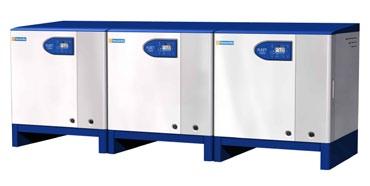


1 Hamworthy Fleet Horizontal Floor Standing Condensing Boilers Natural Gas Outputs 40kW to 350kW 5 YEAR HEAT EXCHANGER WARRANTY

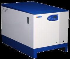
2 Fleet H Floor Standing Horizontal Boilers The Fleet range of commercial boilers has been designed by Hamworthy, using our extensive knowledge and experience, to meet the needs of the UK heating market. Featuring our innovative cast aluminium alloy sectional heat exchanger, which is rated to 6 bar operating pressure, the floor standing Fleet Horizontal range is available in 13 models with outputs from 40kW to 350kW. Designed for high efficiency 80/60 C circuits or 50/30 C condensing performance, with efficiencies up to 109%, Fleet Horizontal boilers take less space than traditional boilers and offer a good choice of outputs to optimise the number of boilers used in a system, being mindful of the life time costs associated with servicing heating plant. Environmental credentials are reinforced by low NOx levels achieving European Class 5 performance. The pre-mix modulating burner technology is designed for high efficiency performance and the control system uses the ultra reliable Siemens platform, which enables a comprehensive range of controls options to be offered. Each boiler is equipped with its own integral pump, managing the flow through the boiler, and may remove the need for a primary circuit pump. Naturally, the Fleet Horizontal range of boilers is available with convenient options to simplify and reduce the cost of installation, including pipework kits and a choice of flue systems, including open flue or room sealed, with concentric or twin duct options. Close load matching Excellent condensing performance Compact close to wall design Comprehensive flue options Factory tested pipe kits Extensive controls capability BENEFITS Providing many of the benefits associated with wall hung boilers, the Fleet Horizontal range of floor standing modular boilers feature a robust commercial heat exchanger which achieves complete versatility through its sectional design. Options Pipework header kits with frame-set Choice of flue systems Flue header kits Single or multiple boiler controls Low loss headers Fleet Horizontal floor standing boilers with pipe kits and room sealed concentric flue system 2


3 Fleet H Condensing Boilers Floor standing modular boilers were first pioneered by Hamworthy in the 1960 s and this latest Fleet Horizontal range surpasses all previous standards. All the benefits of modern wall hung boilers have been designed into the Fleet Horizontal floor standing range, to offer alternative solutions which can save time during installation. High outputs on small footprints maximise the use of plant room space and the Fleet Horizontal boilers are as versatile as their wall hung counterparts, with neat factory assembled frame sets and pipework header systems which fit above the boiler casings, minimising the space required behind the boiler. Flue systems are very versatile with a choice of open flue or room sealed with concentric or twin duct, to ensure that Fleet boilers can be installed in plant room locations from basement to rooftop and anywhere in between. Concentric flues systems are capable of runs up to 60m in length whilst twin duct room sealed configurations can achieve up to 100m, depending on model selection. For open flue applications with multiple boiler header systems, flues runs up to 150m are possible. Refer to pages 26 to 35 for further details of flue systems. Fully modulating pre-mix burners ensure building loads are accurately matched, and with optional boiler sequence controls, the optimum number of boilers to meet demand is always guaranteed. Built in Hamworthy s Poole factory, high quality construction and reliability is assured, with every boiler passing a pre-delivery audit including full wet fire testing. Each boiler is delivered fully assembled within a robust steel casing, and finished in twotone white and grey powder coat to the front cover. Fleet boilers are fitted with comprehensive controls using the Siemens platform, ensuring safe and reliable performance. A wide range of controls options, including wired or wireless sensors, make the Fleet a highly versatile package. The optional Merley sequence controller complements the solution for modular boilers, for either stand alone or building management system (BMS) control. Sectional Heat Exchanger Used throughout our Fleet range of wall hung and floor standing modular boilers, the unique design of Hamworthy s heat exchanger enables our lean manufacturing plant to manufacture boilers easily and quickly to meet fluctuating demand for each output. With just three casting sections, front, rear and intermediate, heat exchangers can be built from stock to deliver outputs from 40kW to 150kW in the Fleet wall hung range, and in module sizes up to 350kW in the floor standing range. The high quality aluminium alloy has better thermal conductivity than stainless steel, and combined with the strength and durability of our pressure die cast aluminium heat exchanger technology, delivers exceptional operating performance with ultra clean emissions and a long service life. Fleet sectional heat exchanger. Heat Exchanger 5 Year Warranty Fleet condensing boilers are supplied with our extended five year warranty on the heat exchanger as standard. As with any aluminium alloy heat exchanger, it is important that approved water treatment is maintained throughout the life of the boiler. All other components carry a standard two year warranty on parts. Where the product is commissioned by Hamworthy Service Engineers, then the warranty also covers labour for the warranty period, subject to servicing and warranty conditions. Boiler Output Selection Chart Outputs (kw) No. of Boilers
4 Specification Heat Exchanger Quality Assurance Specifically designed for the Fleet boiler range, the all new sectional cast silicon aluminium alloy heat exchanger delivers rapid thermal response with robust construction, assuring a long service life. Manufactured using high pressure die casting to provide maximum strength, the process allows intricate mouldings and adherence to close manufacturing tolerances, ensuring precise fin detail for exceptional performance and reliability. Silicon aluminium alloy has excellent pouring properties resulting in consistently high quality castings combined with excellent corrosion resistance. Casting sections are first pressure tested individually at the foundry and then once again as a heat exchanger assembly in our factory, to 1½ times the maximum operating pressure, assuring water tight heat exchangers capable of continuous operation up to 6 bar working pressure. Condensate Management Due to the high thermal efficiency of all modern boilers, condensation will occur within the boiler during firing from cold start-up, under low load conditions and on condensing boilers when the return temperature falls below the flue gas dew point of 55 C. Typically a 100kW condensing boiler will generate around 13 litres of condensate per hour in condensing conditions. The condensate is typically 3.5pH, so slightly acidic but less so than vinegar, and can be disposed of normally through the drainage system. If in any doubt about local regulations, check with the local water authority. For further details of the condensate drainage requirements, please refer to page 21. An injection moulded polypropylene sump is fitted to the heat exchanger on modules up to 250kW output, which connects to the flue system. On the two largest outputs, 300kW and 350kW modules, the sump is manufactured from high grade fully welded stainless steel. Condensate is drained safely via a water trap to a connection for the drainage system. The condensate drain is a generous size to ensure easy flow of condensate, and the boiler includes a safety interlock to indicate any flue or condensate blockage, protecting the boiler from potential damage. Burner A cylindrical fully modulating pre-mix burner is positioned centrally within the heat exchanger and is constructed using a FeCrAl Aconit woven mesh. This design of burner provides excellent flame stability across the full range of modulation from 20% to 100%. Utilising a spark ignition system, the burner is lit directly, and flame proving is achieved by means of a flame rectification probe. Gas Train Gas and air are precisely mixed before entering the burner using a zero governor gas valve arrangement. This is achieved by measuring the pressure drop across a venturi at the fan inlet and adjusting the gas pressure accordingly. Low Emissions All Fleet boilers achieve European Class 5 performance for NOx emissions. The woven fibre construction of the burner delivers consistent gas distribution with resultant low flame temperatures and NOx emissions as low as 35 mg/kwh. Efficiency Fleet condensing boilers achieve a full load efficiency up to 88% gross (98% nett), whilst at part load the efficiency rises to 98% gross (109% nett). This equates to seasonal efficiencies up to 97.4% gross, far exceeding the Building Regulations minimum seasonal efficiency requirements of 86% gross for new buildings and 82% gross for existing buildings, using natural gas. Safety Relief Valve Each boiler is equipped with an individual 7 bar safety pressure relief valve with discharge pipe. Flue Gas Temperature Protection Whilst the operating flue gas temperature is very low, ~65 C at 80 C flow temperature, the flue system is further protected with a flue gas temperature sensor that prevents firing of the boiler should the flue gas temperature exceed 85 C. Flue System Condensate Discharge In addition to the boiler condensate drainage, it is important that the flue system is drained independently, to avoid flue condensate running back through the boiler. This is particularly important where mixed materials are used in the flue system, such as aluminium and stainless steel. Please refer to the flue section on pages 24 to 35 for further details. Delivery Fleet Horizontal floor standing boilers are delivered to site fully assembled from the factory. Each boiler has a pallet design base and can be manoeuvred easily using a pallet truck, and will pass through a standard single doorway. Building Regulations Part L All Fleet boilers comply with the requirements of Building Regulations 2010 Part L, easily exceeding the minimum seasonal efficiency requirements for new and existing buildings as defined in Approved Documents L2A Conservation of fuel and power in new buildings other than dwellings, and L2B Conservation of fuel and power in existing buildings other than dwellings. For Fleet seasonal efficiency data, please refer to the data tables on pages 8 & 9. 4

5 Heat exchanger Ignition transformer Ducted air inlet Ignition spark electrode Gas valve Pre-mix fan Flue gas pressure switch Boiler LMU Gas isolating valve Safety relief valve Flow switch On/off switch Pump Note: Casing parts and wiring removed for clarity. Fleet Horizontal boiler Layout The Fleet Horizontal range of floor standing boilers can be installed as either single units or as part of a modular arrangement. Up to four boilers can be connected using prefabricated pipework kits which run above the boilers. The use of pre-fabricated pipework can greatly reduce on site installation time. All pipe kits are supplied fully assembled and factory tested, complete with the necessary interconnecting fittings and valves. Refer to page 7 for further details. Flue Terminal Location All condensing boilers will produce condensate due to their high thermal efficiency. One effect of this condensate production is to produce pluming from the flue terminal, and careful consideration must be given to the location of the flue terminal. Should pluming be a concern, then the flue system should be designed to discharge at high level so as not to cause a visual intrusion to the building occupants. Integral Pump Each boiler is fitted with an integral pump ensuring the correct flow rate is achieved. The pump is started on each firing cycle and equipped with five minute pump overrun to remove residual heat, plus a periodic-kick feature to reduce the risk of pump seizure. The pump is matched to provide 20 C t temperature differential across the boiler. Using an integral pump with each boiler module reduces standby losses to an absolute minimum and may also remove the need for a dedicated primary circuit pump, provided there is sufficient residual pump head to overcome the primary circuit resistance. Refer to page 19 for details. Pump operation flow protection is provided via a flow switch in the water return of each boiler, ensuring the boiler cannot fire when there is insufficient flow, (or no water content) protecting the boiler from potential damage. 5

6 Controls Overview Boiler Controls Fleet boilers can be installed in a wide variety of configurations, from single boiler applications to multiple boilers controlled locally or by a building management system. Each boiler features an extremely versatile microprocessor based boiler control system that can be tailored to meet the exact needs of the heating system, and capable of integrating the boiler and other system components. Every Fleet boiler is equipped with the following control features as standard: Remote on/off control input Remote modulation input External air temperature sensor input Remote interlock signal input Volt free contacts Frost protection Clip in modules on the LMU Temperature Control All Fleet boilers are fitted with a manual reset limit thermostat set to 100 C. An electronic temperature control thermostat regulates the boiler flow temperature up to a maximum of 90 C. Fleet boilers also incorporate a return temperature sensor, which in conjunction with the flow temperature sensor governs the modulation set point of the boiler. Volt Free Contacts All Fleet boilers are fitted with a multi-function clip-in module to provide volt free contacts as standard. Remote alarm signalling is provided for a general fault alarm and boiler normal run indication Volt DC Analog Input The standard multi-function clip-in module also provides a 0-10 volt DC analog signal interface to control the modulation level of the burner, or to set the flow temperature set point. The 0-10 volt signal can be used for remote connection of the boilers to a Building Management System, (BMS) to enable modulating control remotely. LPB Bus Communications Module The optional LPB bus communication clip-in kit is used to connect the boiler LMU control unit to the optional sequence control module. Each boiler in a modular installation requires a clip-in LPB bus communications module to communicate with the boiler sequence controller. External Air Temperature Sensor Fleet boilers can be supplied with an optional external air temperature sensor to exploit the full functionality of the boiler controls, and enable direct temperature compensation on the boiler, maximising the opportunity for condensing operation. When fitted with an external temperature sensor, the boiler s own thermostat is overridden and the flow temperature is controlled as a function of external temperature conditions. Using a range of adjustable compensation slopes built into the standard boiler controls, the flow temperature profile can be tailored to suit the needs of individual heating systems. For multiple boilers, the external temperature sensor should be used be used in conjunction with the optional Merley boiler sequence controller. Frost Protection When fitted with an external air temperature sensor the boiler control system features a two stage frost protection system. Stage one involves turning the integral boiler pump on should the external air temperature fall below 1.5 C. Stage two involves firing the boiler should the internal water temperature fall below 5 C. Whenever the boiler fires the internal pump is automatically switched on. For further details of controls for single boilers refer to page 16 and for multiple boilers, please see page 17. 6
7 Pipe Kits & Flues The Fleet Horizontal range of floor standing boilers are designed with a pallet base for ease of manoeuvring on site, and are available with an optional range of compact floor standing steel fabricated frame-sets which support pipework headers and ancillary fittings above the boiler casings, minimising the space required behind the boiler. Factory assembled frame-sets with pipework header systems facilitate fast installation with the reassurance that pipework is sized to ensure water volume is matched to the boiler operating performance. Every Fleet boiler has an integral boiler pump, so it may not be necessary to include a dedicated primary circuit pump in the hydraulic layout. When using Hamworthy s optional pipework header and low loss header kits to create the primary circuit, the pump within each boiler removes the need for a dedicated primary circuit pump, and reduces standby losses to an absolute minimum. In other circumstances, it may be necessary to have a dedicated primary circuit pump if there is not sufficient residual pump head to overcome the primary circuit resistance. Refer to page 19 for details. Pipework Kits Making multiple boiler installation easier, frame-sets support the pipework and reduce installation time. The pipework includes headers for water flow and return, gas supply and condensate. Individual spill pipes are provided for discharging safety valves to floor level. Final boiler connections to the pipework for flow, return and gas are completed using short stainless steel flexible connectors and quarter-turn ball isolating valves. Frame-sets are designed for freestanding installation, but can be fixed securely to the floor for improved stability. Pipework kits are available for either one or two boilers, and two frame-sets can be joined together to suit applications with three or four boilers. Low Loss Header To complement the pipework kits, a choice of low loss header is available with either a pair of connections for a single secondary circuit, or three pairs of connections for up to three secondary circuits. The low loss headers for use with boilers 40kW to 150kW are sized specifically to suit up to 600kW maximum boiler capacity, whilst low loss headers for use with boilers 175kW to 350kW are sized to suit up to 1400kW. When used in conjunction with a pipework kit, the low loss headers ensure there is sufficient water volume in the primary circuit to operate the boilers safely. Hamworthy low loss headers and pipe kits are sized to enable the primary circuit to be driven by the integral boiler pumps, so a separate primary circuit pump is not required. Individual Flues or Header Systems Flexible flue arrangements allow Fleet boilers to be flued either individually, or in a multiple boiler arrangement with common flue header. Flue systems are available in a range of sizes, manufactured in polypropylene, with EPDM lip seal to create a pressure tight installation. For larger sizes, the flue headers are manufactured in high quality stainless steel fully welded components, featuring a tri-lip silicone sealing ring to ensure a water tight and pressure tight solution. Flue solutions include both room sealed and open flue configurations. Room sealed flues are available with concentric horizontal or vertical arrangements, or twin duct systems. Open flue systems are available for both horizontal and vertical termination. Room Sealed Flue Systems The room sealed flue options for Fleet boilers offer great flexibility in the design, location and routing of the flue system. The flue components have been matched and tested specifically for use with these boilers. This ensures optimum performance from the installation and simplifies the necessary sizing calculations. Concentric flue systems type C13 - Horizontal termination (40kW to 150kW models only) Concentric flue systems type C33 - Vertical termination Twin duct flue systems type C53 - Horizontal flue termination - Horizontal air inlet Twin duct flue systems type C53 - Vertical flue termination - Horizontal air inlet Conventional Open Flue Systems The Fleet is also suitable for connection to an open flue system. Open flue applications can utilise the same flue components as the twin duct room sealed system. Open flue systems type B23 - Horizontal termination Open flue systems type B23 - Vertical termination Flue Header Systems Alternatively for systems where multiple boilers are installed, a modular header can be used in conjunction with a common chimney. Open flue systems type B23 - Offtake to header system Open flue systems type B23 - Flue header systems For further details of flue systems available with the Fleet Horizontal range of floor standing boilers, refer to pages 26 to 35. Design & Install Hamworthy's extensive knowledge of combustion systems, and the flue requirements for each boiler, makes a boiler and flue package the perfect solution for some projects. Offering a comprehensive range of flue and chimney equipment for natural draught, fan assisted and fan dilution applications, Hamworthy can provide a comprehensive flue design and installation package. 7
8 Technical Data Boiler Model F40H F50H F60H F70H F85H F100H F125H F150H Building Regulations seasonal efficiency gross (%) Boiler output 50/30 C kw Btu/h x Energy Boiler output 80/60 C Boiler input (gross) Maximum kw Btu/h x 1000 kw Btu/h x Boiler input (nett) Maximum kw Btu/h x Boiler output Minimum kw 80/60 C Btu/h x Water content (not including headers) litres Water Design flow 20 C Δt rise Residual pump 20 C Δt rise l/s kpa m Maximum water pressure barg 6.0 Gas Gas flow rate natural gas (G20) Maximum Gas inlet pressure natural gas (G20) m 3 /h mbar 17.5 Minimum 20.0 Nominal 25.0 Maximum Approx. Flue gas 15 C, 9.0% CO2, N.T.P m 3 /h Flue Maximum flue gas temperature C 65 NOx Emission (DAF) European Class 5 mg/kwh Pressure at flue outlet Pa mbar Water flow/return connections Rp1" Rp1 1 /4" Connection Gas inlet connection R 3 /4" R1" Nominal flue diameter (I/D) mm Safety valve (pipe tail) mm 22 Condensate trap connection(s) (O/D) mm 40 Electrics Power consumption maximum W Nominal supply voltage Module current Start Amps Run Amps V 1Ph 50Hz Approx. shipping weight kg
9 Technical Data Boiler Model F175H F200H F250H F300H F350H Building Regulations seasonal efficiency gross (%) Boiler output 50/30 C kw Btu/h x Energy Boiler output 80/60 C Boiler input (gross) Maximum kw Btu/h x 1000 kw Btu/h x Boiler input (nett) Maximum kw Btu/h x Boiler output Minimum kw 80/60 C Btu/h x Water content (not including headers) litres Water Design flow 20 C Δt rise Residual pump 20 C Δt rise l/s kpa m Maximum water pressure barg 6 Gas Gas flow rate natural gas (G20) Maximum Gas inlet pressure natural gas (G20) m 3 /h mbar 17.5 Minimum 20.0 Nominal 25.0 Maximum Approx. Flue gas 15 C, 9.2% CO2, N.T.P m 3 /h Flue Maximum flue gas temperature C 60 NOx Emission (DAF) European Class 5 mg/kwh Pressure at flue outlet Pa mbar Water flow/return connections R1½" R2" Connection Gas inlet connection R1" R1¼" Nominal flue diameter (I/D) mm 130 Safety valve (pipe tail) mm 22 Condensate trap connection(s) (O/D) mm 40 Electrics Power consumption maximum W Nominal supply voltage Module current Start Amps Run Amps V 1Ph 50Hz Approx. shipping weight kg
10 Dimensional Details crs E H 50* 700 D 400 Front view Plan view 300 Note: * Space between boilers to allow for access to electrical gland plate and to suit Hamworthy pipe kits. Flow connection Air inlet connection Gas connection Return connection Safety valve Flue connection C F E Condensate arrangement on F300H and F350H models only, with stainless steel sump. B A Electric gland holes 21mm dia x3 Condense trap 140 G All dimensions in mm. Rear view Side view Model Dimension F40H F50H F60H F70H F85H F100H F125H F150H Casing depth A Flue depth B Flue diameter C* 100 Clearance - Rear D** 250 Flue Centreline E 50 Condense Centreline F 150 Condense Centreline G 25 Maintenance clearance - minimum H 450 C* the boiler flue connection may be suitable for use with concentric flue systems or twin duct flue systems. For full details of flue options see pages pages 26 to 35 D** when using Hamworthy pipe kit, otherwise, 450mm. 10
11 Dimensional Details Optional Room Sealed Flue Layout F crs 1426 G A B 700 Optional room sealed concentric flue connection Air inlet connection 100 dia Flue connection C* Note: The location of the optional room sealed flue connection is shown to accommodate the Fleet Horizontal pipe kit, which is positioned above the boiler casing. If this pipe kit is not being used, then the height of the connection can be reduced. For full details of flue systems for Fleet Horizontal boilers, refer to pages 26 to 35. All dimensions in mm Model Dimension F175H F200H F250H F300H F350H Casing depth A Flue depth B Flue diameter C* Clearance - Rear D** Flue Centreline E Condense Centreline F Condense Centreline G Maintenance clearance - minimum H 600 C* the boiler flue connection may be suitable for use with concentric flue systems or twin duct flue systems. For full details of flue systems, refer to pages 26 to 35 D** when using Hamworthy pipe kit 11
12 Dimensional Details Fleet Horizontal Boiler Pipe Kits for Boiler Models F40H to F150H Single Boiler 1280 Arrangement (across outside of legs) Low Loss Header - Three Pair Connections (6 Port) L 11 Pocket for temperature sensors x dia A.A.V. Secondary flow Flow Primary flow Return Primary return Gas (across outside of legs) Condense 1321 nom 1130 nom Secondary return 179 nom 369 nom 559 nom 949 nom 1139 nom 1329 nom 1498 nom All dimensions in mm. Drain Adjustable Foot Two Boiler Arrangement K Flow Condense 40mm dia Flow Return Gas Return Gas 991 nom 1130 nom 1321 nom Condense 40mm dia (across outside of legs) (across outside of legs) Adjustable 30 80mm J 1506 Model 3014 Dimension F40H 10 F50H F60H F70H F85H F100H F125H F150H 1506 Overall depth J Header depth K Width L Flow DN50 - PN16 DN65 - PN16 Return DN50 - PN16 DN65 - PN16 Gas R1½" R2"
13 (across outside of legs) 7 Adjustable 30 80mm Dimensional Details Fleet Horizontal Boiler Pipe Kits for Boiler Models F40H to F150H Low Loss Header - Single Pair Connections (2 Port) dia A.A.V. Three Boiler Arrangement 3034 Primary flow Secondary flow Primary return Secondary return nom 1321 nom 1130 nom Pocket for temperature sensors x 2 Drain 951 nom 1351 nom Adjustable Foot (across outside of legs) Conde 40mm All dimensions in mm (across outside L of legs) 11 Sensor Spool Kit dia A.A.V. Sensor Pocket ½"BSP Four Boiler Arrangement dia 1506A.A.V Secondary flow Flow 10 Return Gas Primary flow Secondary flow Primary flow 2020 nom 1405 nom Primary return 1130 nom 120 Secondary return 500 nom 1500 nom nom 1405 nom Primary return 1130 nom 225 nom Secondary return 500 nom nom nom 780 (across outside of legs) 1500 nom 1775 nom Condense Drain Header dia 250 Notes: 11 Header dia Pocket for temperature Adjustable Pocket for temperature Adjustable 1. Pipe work is supported on a freestanding frame and the boilers will be installed between 1506 sensors x 2 Foot sensors x 2 Foot the frames. Frame sets are supplied as a single boiler set or two boiler set, for connecting together on site. 2. System pipe connections can be made to either end of the pipe kit. Blanking flanges provided. 3. Low loss headers can be fitted to either end of the pipe kit. 4. Sensor spool kit comprises a pair of spool pieces for flow & return connections, and these can be fitted to either end of the pipe kit. 5. If low loss headers are used, then a sensor spool is not required. Drain 13
14 (across outside of legs) Dimensional Details Fleet Horizontal Boiler Pipe Kits for Boiler Models F175H to F350H Single Boiler Arrangement 2280 (across outside of legs) Low Loss Header - Three Pair Connections (6 Port) dia A.A.V Secondary flow (across outside of legs) Flow Return Gas Condense 2020 nom 1405 nom Primary flow Primary return 1130 nom Drain 225 nom Header dia 250 Secondary return 500 nom 775 nom 1225 nom 1500 nom 1775 nom All dimensions in mm. Pocket for temperature sensors x 2 Adjustable Foot Two Boiler Arrangement Flow Flow Return Gas Condense 40mm dia Return Gas 931 nom 1130 nom 1405 nom Condense 40mm dia (across outside of legs) (across outside of legs) 78 Adjustable 30 80mm J Model Dimension F175H F200H F250H F300H F350H Overall depth J Flow DN125 - PN16 Return DN125 - PN16 Gas R2½" 14
15 return Secondary return Adjust nom 1321 nom 1130 nom Pocket for temperature sensors x 2 Dimensional Adjustable Details Foot Drain 951 nom 1351 nom Fleet Horizontal Boiler Pipe Kits for Boiler Models F175H to F350H Low Loss Header - Single Pair Connections (2 Port) 54 Three Boiler Arrangement 3030 (across outside of legs) dia A.A.V dia A.A.V Secondary flow Primary flow Secondary flow Primary flow 2020 nom 1405 nom Primary return 1130 nom Pocket for temperature sensors x 2 Drain Sensor Spool Kit Sensor Pocket ½"BSP Secondary return Header dia 250 Adjustable Foot 500 nom 1500 nom 2020 nom 1405 nom Primary return 1130 nom 54 Drain All dimensions in mm. Pocket for temperature sensors x 2 Adjustable Foot Four Boiler Arrangement nom Header dia Secondary return 500 nom 775 nom 2280 (across outside of legs) nom 1500 nom 1775 nom (across outside of legs) Flow Return Gas Conde 40mm (across outside of legs) Condense (across outside of legs) 2280 Notes: 1. Pipe work is supported on a freestanding frame and the boilers will be installed between 1506the frames. Frame sets are supplied as a single boiler set or two boiler set, for connecting together on site. 2. System pipe connections can be made to either end of the pipe kit. Blanking flanges provided. 3. Low loss headers can be fitted to either end of the pipe kit. 4. Sensor spool kit comprises a pair of spool pieces for flow & return connections, and these can be fitted to either end of the pipe kit. 5. If low loss headers are used, then a sensor spool is not required. 15
16 Control Details Fleet Horizontal - Single Boilers The control options for single Fleet Horizontal boilers are different to those for multiple boilers. Please refer to page 17 for controls on multiple boilers. All controls functions are managed via the boiler management unit Siemens LMU64. Using a combination of options, the level of control is expandable for up to 2 heating circuits and 1 domestic hot water cylinder. A circulation pump overrun timer is incorporated within the boiler LMU. Programmable Room Sensor A Fleet single boiler system can be fitted with a single programmable room sensor, which should be located in the first heating zone. This room thermostat allows heating circuit management to be based on both the internal and external air temperature. The boiler will manage the heating circuit pump via a contactor according to the program requirements of the programmable room unit. Features: Individual 7 day program with auto summer / winter hour change for heating circuit 1, heating circuit 2 and DHW 3 periods per day per time program Constant or variable temperature flow Compensated flow temperature based on external and room air temperatures Optimised start / stop based on external and room air temperatures Building frost protection based on room air temperature Summer shutdown based on external air temperature Holiday period with frost protection Reduced temperature, night set back for non occupancy hours Pump kick for pumps controlled from boiler Programme lock to prevent tampering Individual temperature settings for each zone To achieve full functionality an external air sensor must be fitted. Options for a Single Boiler only Programmable room sensor External air sensor 2nd Heating Circuit Clip-in Relay Kit DHW Cylinder Sensor Kit External Air Sensor An optional external air temperature sensor may be wired directly to the boiler to exploit the direct weather compensation functionality of the boiler controls. This sensor may be connected to the control scheme and should ideally be positioned on an external wall with northerly aspect. 2nd Heating Circuit Clip-in Relay Kit To control a second heating circuit, an additional clip-in relay kit is required for fitting directly to the LMU. The kit comprises a relay and water temperature sensor complete with pocket. This kit provides outputs for a pump and mixing valve. Mixing valve allows second heating circuit to operate at a different temperature set-point to heating circuit 1. Second heating circuit should operate at the same or lower temperature than circuit 1, e.g. underfloor heating. Programmed via the programmable room sensor Compensated flow based on external air temp and using a curve separate to that of heating circuit 1 owing to mixing valve Optimised start/stop based on external air temperature Frost protection based on water temperature in second heating circuit For the second heating circuit, the boiler will manage the circuit pump and/ or mixing valve via contactors, according to the program requirements of the programmable room sensor and the water temperature sensor. Only one programmable room sensor may be connected, therefore the second heating circuit management is derived from time control and external air temperature measurement. DHW Cylinder Sensor Kit This kit is for a domestic hot water (DHW) circuit directly controlled from the boiler, but programmed via the programmable room sensor, and features: Immersion sensor complete with pocket DHW cylinder sensor and pump output directly from boiler LMU Frost protection based on stored water temperature Reduced storage temperature for non-occupancy hours Anti-Legionella function For the DHW cylinder circuit, the boiler will manage the primary coil pump according to the program requirements of the programmable room unit and the DHW cylinder sensor. 16

17 Control Details Fleet Horizontal - Multiple Boilers The control options for multiple Fleet Horizontal boilers are different to those for single boilers. Please refer to page 16 for controls on single boilers. Sequence Controller LPB Bus For use with multiple boilers, the optional Merley sequence controller can control up to 16 boilers. Communication between the boilers and sequence controller is facilitated via the LPB bus. Merley is the latest generation boiler sequence controller for multiple boiler installations. Using the Siemens controls platform, Hamworthy boilers can be controlled to share the load between boiler modules to maximise efficiency and system performance. Merley wall mounted sequence controller As a standalone device with autonomous control of the boilers, the controller can be extended to sequence control the boilers and also to manage a complete heating circuit as well as a domestic hot water (DHW) cylinder. A range of room and external air temperature sensors, including wireless options, ensures comfort levels within the building are maintained. When integrated with a building management system (BMS), the Merley operates only as a boiler sequence controller, receiving the required operating temperature from the building management system via a 0 to 10 volt analog signal. Each sequence control system is supplied with a smart digital interface display allowing the user to monitor the current operating status of the boilers, and also the building where the Merley is used to control a heating zone and hot water cylinder. Full details of the Merley sequence controller are provided in publication, , available to download at or request a printed copy, Tel: Options for Multiple Boilers only Boiler sequencing cascade controller LPB bus communications Clip-in module Choice of room sensors External air sensor Hard wired or wireless controls DHW Cylinder Sensor Kit The Merley boiler sequence controller can be supplied within a dedicated housing for wall mounting or as a loose kit for integrating within a plant room control panel. Wall Mounted Controller Merley sequence controllers are available factory assembled within a robust steel enclosure suitable for wall mounting, with the digital interface display pre-mounted to the housing door. The sequence controller is mounted to a DIN rail attached to the panel back plate assembly, with electrical trunking to simplify routing for site cables to the appropriate wiring terminations. A cable gland plate is located on the underside of the control panel with 6 loose cable glands supplied for fitting on site. Loose Kit Controller For installations where the sequence controller will be integrated within an existing or new plant room control panel, the Merley sequence controller can be supplied in loose kit form. A suitable space must be allocated within the plant room control panel for mounting the sequence controller to the back plate and for mounting the digital display to the control panel door. Boiler Sequence Control Strategies The Merley sequence controller can be configured to sequence boilers in traditional cascade mode or in unison mode. Cascade Control Steps a boiler module on at its lowest rate and then modulates it to its maximum rate, before switching on the next boiler module to match the system load. Maintains the lowest number of boiler modules in operation for a given heat load. This control strategy is particularly suited to boilers operating in constant temperature systems where there is no great efficiency advantage to be gained from operating boilers at part load. Unison Control Steps each boiler module on in turn at its lowest rate, and then modulates all boiler modules simultaneously to higher rates to match the system load. This method of sequencing can offer higher operating efficiencies, taking advantage of the higher part load efficiencies available at low firing rates. This control strategy is particularly suited to condensing boilers operating in variable temperature systems where low water temperatures and part load boiler operation allows optimum boiler operating efficiency to be achieved. 17
18 Application & System Data The installation of the boiler MUST be in accordance with the relevant requirements of the Gas Safety Regulations, Building Regulations, IEE Regulations and the Water Supply (Water Fittings) Regulations. It should also be in accordance with any relevant requirements of the local gas region and local authority and the relevant recommendations of the following documents : These British Standard Codes of Practice and additional publications have relevant recommendations regarding the installation of Fleet boilers. British Standards BS 5440 Part 1 Flueing and ventilation for gas appliances of rated input not exceeding 70kW nett. Installation of gas appliances to chimneys and for maintenance of chimneys. BS 5440 Part 2 Flueing and ventilation for gas appliances of rated input not exceeding 70kW nett. Installation and maintenance of ventilation provision for gas appliances. BS 6798 Installation and maintenance of gas-fired boilers of rated input not exceeding 70kW nett. BS 6644 Installation of gas-fired hot water boilers of rated inputs of between 70kW nett and 1.8MW nett. BS 6700 Design, installation, testing and maintenance of services supplying water for domestic use. BS EN Specification for installations inside buildings conveying water for human consumption Part 2: Design BS 6891 Installation of low pressure gas pipework of up to 35mm (R1 ¼) in domestic premises. BS 6880 Part 1,2 & 3 Code of practice for low temperature hot water heating systems of output greater than 45kW BS 7074 Application, selection and installation of expansion vessels and ancillary equipment for sealed water systems. Part 2 Code of practice for low and medium temperature hot water heating systems. BS 7671 Requirements for electrical installations. IEE Wiring Regulations. Seventeenth edition. I. Gas E. Publications IGE/UP/1 Strength testing, tightness testing and direct purging of industrial and commercial gas installations. IGE/UP/1A Strength testing, tightness testing and direct purging of small low pressure industrial and commercial natural gas installations. IGE/UP/2 Installation pipework on industrial and commercial premises. IGE/UP/10 Installation of flued gas appliances in industrial and commercial premises. Health and Safety Executive Guidance note PM5 - Automatically controlled steam and hot water boilers. CIBSE Publications CIBSE Guide B Heating, ventilating, air conditioning and refrigeration. CIBSE Guide H Building Control Systems CIBSE Guide Energy Efficiency in Buildings CIBSE Commissioning Code B: 2002 Third edition of the 1956 Clean Air Act Memorandum Department of the Environment, Scottish Development Department & Welsh Office. Location The location chosen for the boiler must permit the provision of a satisfactory flue system and an adequate air supply. The location must also provide adequate space for servicing and air circulation around each unit. This includes any electrical trunking laid along the floor and to the appliance. Fleet floor standing boilers should be positioned on a level non-combustible surface that is capable of supporting the boiler weight when filled with water, plus any ancillary equipment. Adequate space should be allowed for installation and servicing. Any combustible material adjacent to the boiler and the flue system must be so placed or shielded to ensure that its temperature does not exceed 65 C. Further details regarding boiler location are given in BS & BS 5440 part 2. Water Systems Fleet boilers are suitable for installation in sealed heating systems or open vented systems. However in the interests of system cleanliness, ease of maintenance, water quality and reduced oxygen ingress Hamworthy strongly recommend sealed systems are considered for use where ever possible. If open vented systems must be used, the height of the feed and expansion tank as well as the height of the open vent pipe must be designed correctly. See advice on page 19. Sealed Systems Compliance with the requirements of Health and Safety Executive Guidance Note PM5 can also be assured by using an automatic pressurisation unit with expansion vessel, such as the Hamworthy Chesil range of pressurisation units. Such units can be set to ensure minimum head requirements are maintained and provide alarm facilities for high and low system pressure with interlock circuits for the boiler plant. Expansion vessels for sealed systems must be sized to suit the system volume to which they are attached as well as maintaining hot working pressure within the maximum operating limits of the plant. For more details regarding sealed systems and pressurisation units, see publication Hamworthy Chesil Pressurisation Units. 18
19 Open Vented Systems With open vented systems there are a number of key considerations to ensure satisfactory operation of the boilers: Height of the feed and expansion tank above the boilers Height of the open vent pipe above the feed and expansion tank water level Open vent and cold feed pipe size Volume of feed and expansion tank Structural integrity of building to support feed and expansion tank weight Hamworthy strongly recommend sealed systems are considered where ever possible. Tank Height Health and Safety Executive Guidance Note PM5 states that "hot water boilers should have an automatic control apparatus to cut off fuel to the burners of gas fired plant when the water at or near the boiler flow outlet rises to a pre-determined temperature. This should provide a margin of at least 17 C below the temperature of saturated steam corresponding to the pressure at the highest point of the circulation system above the boiler. " To comply with this recommendation, the minimum system pressure is dependent on system design flow temperatures and in the case of modular installations, the temperature rise across each module. Open Vent Pipe Height The height of the open vent pipe discharge above the feed and expansion tank water level must be sufficient to absorb the residual head pressure surge from the boiler pump on initial start up. The boiler pump is sized to overcome the boiler hydraulic resistance and to provide additional head to overcome system resistance. This additional head for the heating system is the residual pump head which upon pump start up will cause a momentary rise in water level within the open vent pipe whilst circulation around the system gets going. The height of the open vent pipe discharge above the water level within the tank must be greater than the equivalent residual pump head. Single Installations The minimum pressure at the highest point of the circulating system should be equal to the gauge pressure equivalent to the temperature of saturated steam at this point. The temperature of saturated steam is obtained by adding 17 C to the required flow temperature from the boilers. Example: Required flow temperature from boilers 90 C Safety margin 17 C Equivalent saturated steam temperature 107 C From steam tables corresponding gauge pressure to be present at the highest point of the circulating system = 0.3bar 3.1m System head available at Fleet boilers must never be less than 0.5 bar 5.1m. Modular Installations The minimum pressure at the highest point of the circulating system should be equal to the gauge pressure equivalent to the temperature of saturated steam at this point. The temperature of saturated steam is obtained by adding 17 C to the required flow temperature from the boilers. Example: Required flow temperature from boilers 80 C Safety margin 17 C Equivalent saturated steam temperature 97 C From steam tables corresponding gauge pressure to be present at the highest point of the circulating system = 0.09bar 0.92m System head available at Fleet boilers must never be less than 0.5 bar 5.1m. Residual Pump Head Each boiler has an integral pump which reduces standby losses to an absolute minimum and may also remove the need for a dedicated primary circuit pump, provided there is sufficient residual pump head to overcome the primary circuit resistance. Boiler Model Residual Pump Head (m) F40H 2.7 F50H 2.0 F60H 1.4 F70H 0.6 F85H 4.2 F100H 3.4 F125H 2.2 F150H 3.0 F175H 3.0 F200H 1.6 F250H 3.25 F300H 1.7 F350H 6.6 Open Vent & Cold Feed Every boiler or group of boilers should have an open vent pipe and cold feed pipe installed between the boiler and the first water isolating valve. The minimum bore of these pipes per installation is shown in the table below. Refer to BS 6644 for further information. Boiler Output Open Vent Size Cold Feed Size <60kW 25mm 19mm 60kW 150kW 32mm 25mm 150kW 300kW 38mm 32mm 300kW 600kW 50mm 38mm 601kW - 800kW 65mm 50mm 801kW kW 80mm 50mm 19
20 Application & System Data Gas Supply Pipes Supply pipes must be fitted in accordance with BS6891 or IGE/UP/2 as appropriate. Pipework must be of adequate size. Pipes should not be of a smaller size than the boiler gas connections. The complete installation must be purged and tested for soundness as described in BS6891 or IGE/UP/1 and IGE/ UP/1A as appropriate. The information in table 1 opposite shows pipe lengths from gas meter outlet to appliance which will produce approximately 1mbar pressure loss. This table must be used in conjunction with losses of various fittings shown in table 2 below. Note: Table 1 is based on CIBSE guidance for flow of natural gas in medium grade steel pipes and does not include allowance for any pipe fittings i.e. a straight continuous pipe. Allowances for basic pipe fittings are provided in table 2 and must be subtracted from the maximum pipe length derived from table 1. This information is provided for guidance only and does not replace the requirement for full and accurate pipe sizing to suit the site layout and boilers in use. Adequate Water Flow The Fleet boiler is designed as a rapid response, low water content unit, to run continuously with maximum reliability. Care should be taken in the initial design and layout, having due regard for adequate water flow through the boilers, and the influence of the control system. Fleet boilers are equipped with individually matched pumps designed for 20 C differential temperature across the boiler. Hamworthy strongly recommend that Fleet boilers are installed using a primary circuit design to ensure secondary circuit conditions cannot have influence over reliable operation of the boilers. Boiler Safety Valve Every Fleet boiler is fitted with a dedicated safety valve designed to safeguard the boiler and relieve pressure should boiler pressure exceed 7barg. For heating systems where the maximum operating pressure is lower than 7barg, an additional system safety valve should be specified and installed in the common system flow pipework. Any additional safety valve must be sized for the entire boiler plant load in accordance with the requirements of BS Table 1- CIBSE Guidance for Flow of Natural Gas in Medium Grade Steel Pipes Boiler Output Maximum length of gas pipe (metres) Pipe diameter kw 25mm 40mm 50mm 65mm 80mm 100mm Table 2 - Allowances for basic pipe fittings Pipe Length Reduction per Fitting (metres) Fitting Pipe diameter 25mm 40mm 50mm 65mm 80mm 100mm Elbow Tee Radius bend
21 System Feed Water Quality Modern heating systems often contain a diverse mix of metals, which when combined with the varying chemical composition of supply water, can lead to corrosion. It is therefore important to treat water, where required, to ensure long term satisfactory operation of the boilers and heating system. Hamworthy recommend a water treatment specialist is appointed to undertake analysis of the water and to recommend suitable cleaning and dosing regimes, to ensure the quality of system and make up water remains within the following tolerances throughout the life of the installation: Water Properties Permitted Levels Acidity level 7 to 8 ph (untreated) 7 to 8.5 ph (treated) Chlorides (Cl) 150 mg/l 350 mg/l up to 70kW output* Calcium Carbonate (CaCO3) 200 mg/l from 70kW to 200kW output* 150 mg/l from 200kW to 500kW output* 50 mg/l above 500kW output* Iron (Fe) 125 ppm (treated) Copper (Cu) 1 ppm (treated) Aluminium (Al) 1 ppm (treated) Conductivity 800μs/cm at 25 C * Total boiler output As a minimum, system pipe work should be flushed twice with suitable flushing and cleaning agents as recommended by the water treatment specialist. Artificially softened water should be avoided when filling the system. Chemical dosing to avoid corrosion and bacterial growth should be in accordance with the recommendations of the appointed water treatment specialist. To prevent dilution of water treatment in normal operation, it is essential to monitor make up water usage and attend to leaks quickly. Any draining of the system must be co-ordinated with subsequent re-dosing with the correct chemicals to ensure protection is not compromised. Additionally, a coarse filter and dirt separator must be fitted in the return pipe work close to the boilers, and suitable air separation must be provided at high points in the distribution circuits. Full details for water quality requirements are available on request. Condensate Discharge Natural Gas condensing boilers typically produce condensate at a rate of around 13litres per hour per 100kW input energy, when operating at suitable temperatures. A drain connection is fitted to the boiler to enable the disposal of the condensate which is mildly acidic, with a typical value 3.5pH, and can be disposed of normally through the drainage system. If in any doubt about local regulations, check with the local water authority. The condensate drain on each boiler must be connected to a suitable drainage system using corrosion resistant material such as a PVC plastic with glued sealed joints, to prevent the escape of condensate. Drain traps and an open tundish should be incorporated into the design, and the pipework given appropriate protection from physical damage and frost. The pipework should be installed with at least a 3 degrees fall (approximately 50mm per metre). The Fleet optional pipe kit includes plastic pipework to connect the drain from each boiler to a single pipe which should be piped away to a drain in the manner described above. Refer to page 7 for further details of optional pipe kits. The Building Regulations 2010 Approved Document L2A Conservation of fuel and power in new buildings other than dwellings. Approved Document L2B Conservation of fuel and power in existing buildings other than dwellings These new regulations came into force 1st October Compliance with the latest regulations requires a whole building approach to reduction in carbon emissions. The 2010 edition requires the use of heat generating plant as detailed in the supporting 2nd tier guide: Non- Domestic Building Services Compliance Guide Seasonal Efficiency The efficiency data used for evaluating commercial boilers is known as the boiler seasonal efficiency and is calculated using a combination of gross operating efficiency data at both part and full load. New Buildings For Natural Gas, single boiler installations must have a gross boiler seasonal efficiency no less than 86%. For Natural Gas, multiple boilers installations must have no individual gross boiler seasonal efficiency less than 82%, with the combined gross boiler seasonal efficiency no less than 86%. Existing Buildings For Natural Gas, single boiler installations must have a gross boiler seasonal efficiency no less than 82%. For Natural Gas, multiple boiler installations may have individual gross boiler seasonal efficiency less than 82%, with the combined boiler seasonal efficiency no less than 82%. For Natural Gas, all existing building installations must have an effective boiler seasonal efficiency no less than 84%. Where the boiler seasonal efficiency for single and multiple boiler installations lies between 82% and 84%, additional credits can be gained to effectively increase the boiler seasonal efficiency. For full details of available credits, refer to the Non-Domestic Building Services Compliance Guide 2010 Edition. 21
22 Air Supply & Ventilation An adequate supply of fresh air for combustion and ventilation must be provided in accordance with BS5440 and BS6644. Where Fleet boilers are installed as room sealed units the air supply is for ventilation only. Boiler Installations <70kW Nett Rated Input Air supply and ventilation must be in accordance with BS5440. Model Compartment Ventilation Open Flue Compartment Ventilation Room Sealed Fleet F40H Nett heat input 37kW Fleet F50H Nett heat input 46kW Fleet F60H Nett heat input 56kW Fleet F70H Nett heat input 65kW The areas quoted are minimum free areas for ventilation grilles. For further guidance refer to BS5440. Boiler Installations >70kW Nett Rated Input Air supply and ventilation must be in accordance with BS6644. Open Flue Appliances Direct to outside air To room or internal space Direct to outside air To room or internal space High level - 185cm 2 High level - 370cm 2 High level - 185cm 2 High level - 370cm 2 Low level - 370cm 2 Low level - 740cm 2 Low level - 185cm 2 Low level - 370cm 2 High level - 230cm 2 High level - 460cm 2 High level - 230cm 2 High level - 460cm 2 Low level - 460cm 2 Low level - 920cm 2 Low level - 230cm 2 Low level - 460cm 2 High level - 280cm 2 High level - 560cm 2 High level - 280cm 2 High level - 560cm 2 Low level - 560cm 2 Low level cm 2 Low level - 280cm 2 Low level - 560cm 2 High level - 325cm 2 High level - 650cm 2 High level - 325cm 2 High level - 650cm 2 Low level - 650cm 2 Low level cm 2 Low level - 325cm 2 Low level - 650cm 2 Compartment Ventilation - Open Flue Direct to outside air High level - 5cm 2 /kw nett input Low level - 10cm 2 /kw nett input Boiler House Ventilation - Open Flue Direct to outside air High level - 2cm 2 /kw nett input Low level - 4cm 2 /kw nett input Room Sealed Appliances The areas quoted are minimum free areas for ventilation grilles. For nett heat input, refer to technical data table on pages 8 & 9. For further guidance refer to BS6644. General Ventilation Requirements 22 Compartment Ventilation - Room Sealed Compartment Ventilation - Room Sealed Ventilation Grille Openings High and low level ventilation grilles shall be positioned as high and as low as practicably possible. Low level grilles additionally will be located within 1 metre of floor level for Natural Gas. High level grilles are recommended to be positioned within 15% of the boiler room height from the ceiling. High and low level ventilation grilles shall communicate with the same room or internal space where compartment ventilation is used. Where ventilation grilles communicate directly with outside air they shall be positioned on the same wall. Boiler House Ventilation - Room Sealed Direct to outside air To room or internal space Direct to outside air High level - typically 5cm 2 /kw nett input High level - typically 10cm 2 /kw nett input High level - typically 2cm 2 /kw nett input Low level - typically 5cm 2 /kw nett input Low level - typically 10cm 2 /kw nett input Low level - typically 2cm 2 /kw nett input Boiler House Temperatures Additional requirement of BS6644 for multiple boiler installation requires that the air supplied for boiler house ventilation shall be such that the maximum temperatures within the boiler house do not exceed: At floor level 25 C (or 100mm above floor level) At mid level 32 C (1.5m above floor level) At ceiling height 40 C (or 100mm below ceiling height) Air Supply The air supply should be free from contamination such as building dust and insulation fibres from lagging. To avoid unnecessary cleaning and servicing of the boiler modules the boilers should not be fired whilst building work is being undertaken. Where a boiler installation is to operate throughout the summer months, e.g. for domestic hot water production for more than 50% of the time, then additional ventilation allowances are required. Refer to BS6644 for more information.
23 Wiring Diagram The following electrical connections are provided on each boiler: Supply live neutral and earth Boiler general fault alarm signal output Boiler normal run signal output 0 10v analog control signal input Remote on/off control input Remote safety interlock circuit input Earth Mains Supply 230v~50Hz BMS Input Signal Lock-Out Normal Run Powered Output (Option 1) Contacts rated 230v~50Hz, Max 1A BMS Output (Option 2) Low Voltage Live Neutral Live Neutral Secondary Pump Output Live Neutral Powered Output Supply Line Out Neutral Lock-Out Line Out Neutral Normal Run NOT USED 24VDC Ground Remote On/Off Input Signal 0~10V Ground Analogue Input 5VDC Ground Outside Sensor 24VDC Ground Safety Interlock (Link if Not Used) Signal LPB Bus Ground NOT USED NOT USED Electrical Supply An independent isolator and fused electrical supply is recommended for each boiler. Supply 230 volt, 50Hz, single phase. Wiring external to the boiler must be installed in accordance with IEE Regulations and any local regulations which apply. Wiring must be completed in heat resistant 3 core cable, (size 1.0 mm² c.s.a.). Fascia fuse rating is 2 amp. External fuses should be rated 6 amps for each boiler. To prevent drawings excessive current (>1 amp) through the boiler control panel, it is recommended that external pumps are connected via contactors. Electrical Connections There is a gland plate fitted in the bottom of the boiler mounting frame to accept cables for power supply and controls. A single terminal rail is fitted inside the front cover, and all external connections are made to this terminal rail. Remote Signalling Volt free contacts are provided to indicate the following operating conditions: Boiler normal run Boiler general fault 0-10 Volt DC Analog Input A 0-10 volt DC analog signal interface is provided to control boiler from an external Building Management System (BMS). The interface can be configured to control the boiler according to either power requirement or temperature requirement. Remote on/off Facilitating control from an external source the remote on/off circuit is powered at 24V DC and requires a volt free contact device to enable/disable operation. The boiler will operate using its own internal temperature regulation controls in remote on/off operation mode. Remote Safety Interlock Safety devices such as pressurisation units, flue fans etc can be interlocked with boilers using a 24V DC circuit requiring a volt free contact device to permit/prevent operation. 23
24 System Design Primary Circuit Layout When using Hamworthy s optional pipework header and low loss header kits to create the primary circuit, the primary system is sized so that the pump within each boiler removes the need for a dedicated primary circuit pump. The integral pump with each boiler module reduces standby losses to an absolute minimum and guarantees correct flow rates through each boiler, therefore a reverse return pipe work design in the primary circuit is not a requirement, simplifying the design and installation. In other circumstances the primary circuit pipe system must be designed to ensure the residual head of the boiler pumps is sufficient to overcome hydraulic resistance of the pipework at maximum flow rate, otherwise a separate primary circuit pump will be required. For details of the residual pump head to overcome the primary circuit resistance, please refer to page 19. It is important to consider the location of temperature sensors which may be used in conjunction with a sequence controller or site BMS controls. Where optional low loss headers are not used, provision for sensor pockets can be incorporated by use of the optional sensor spool kit which is supplied as a pair for connection to both the flow and return pipe kit headers. Each sensor spool piece is fitted with a pocket with capacity for up to 3 x 6mm sensing elements. If Hamworthy low loss headers are used, then a sensor spool is not required. The low loss header kits have provision for temperature sensors which may be used in conjunction with a sequence controller or site BMS controls. A pocket is provided in the primary flow and return with capacity for up to 3 x 6mm sensing elements in each. For details of optional pipe kits, please refer to pages 7 and 12 to 15. When installing Fleet boilers without the optional pipe kit and sensor spool kit, provision should be made for fitting any required instrumentation such as gauges or temperature sensor pockets. Temperature sensors for a sequence controller or BMS controls for the boiler should be located in the primary flow and return between the boiler and low loss header. Adequate provision should be made for isolating the boilers for the purpose of future maintenance. If using the optional pipe kits, all isolating valves are provided for hydraulic and gas services. Hamworthy optional pipe kit with low loss header for single secondary circuit Boiler 1 Optional Kit Boiler 2 Boiler 3 Drain AAV AAV Dosing Pot Dirt & air separator Dirt & air separator Flow Return Note: - secondary circuit components are not supplied with the HHL pipe kit. Hamworthy optional pipe kit with low loss header for three secondary circuits Boiler 1 Optional Kit Boiler 2 Boiler 3 Dosing Pot Flow Flow Flow Return Return Return Note: - secondary circuit components are not supplied with the HHL pipe kit. 24
25 System Design Typical primary circuit arrangement with low loss header Boiler 1 Boiler 2 Boiler 3 Dosing Pot Dirt & air separator Hydraulic separation of secondary circuits using a plate heat exchanger Boiler 1 Boiler 2 Boiler 3 Dosing Pot AAV Dirt & air separator AAV Flow Return Flow Plate Heat Exchanger Return System Flushing & Water Treatment When installing Fleet boilers, the heating systems must be thoroughly flushed before installing the boilers. Additional measures to safeguard the boilers from existing system debris should include a dirt and air separator in the return pipe from secondary circuits. When using the Hamworthy optional pipe kit and low loss header for 3 secondary circuits, a dirt and air separator should be included in the return pipe from each circuit, to ensure system debris is prevented from reaching the boilers. All systems, new and refurbished should be thoroughly flushed before use. Your attention is drawn to BSRIA guide BG/29/2011 for Pre-Commission Cleaning of Pipework Systems, which provides the latest thinking and good practice cleaning techniques. On new systems, there may be flux residues, greases, installation debris, swarf and mineral oils to remove, whereas existing systems may also contain magnetite sludge, corrosion debris, limescale and slimes. After initial flushing with clean water, the system should be chemically cleaned. Chemical Cleansing Systems should be cleaned, where necessary, with a proprietary system cleaner to improve the cleanliness of the system prior to filling with inhibitor to protect the system. Consideration should be given to the age and condition of existing systems, to minimise the risk of creating leaks due to removal of sludge and exposure to internal corrosion. Primary/Secondary Circuit Separation With older systems it can be advantageous to totally separate the boilers from the secondary circuits using a plate heat exchanger. This method of connection helps to prevent sedimentation within the boilers and for chemical dosing of the boilers to remain unaffected by conditions elsewhere within the heating system. Water Treatment After thoroughly flushing and cleaning the heating systems, an appropriate inhibitor must be added for scale and corrosion protection and to ensure optimum boiler efficiency. It is important to maintain corrosion inhibitor levels throughout the working life of the boiler installation. Correct inhibitor levels also help to keep the boiler clean and prevent a reduction in energy efficiency associated with sedimentation. For details of system feed water quality, refer to page
26 Flue Design - Models F40H to F150H Concentric Room Sealed Flue Systems C13 Horizontal Terminal Floor standing Fleet Horizontal boilers have separate connections for the flue and the air supply at the rear of the boiler. Using this C13 system, the individual ducts from the flue connection and the air inlet converge to a concentric adaptor located above the boiler. From that point, the flue system can be run to the concentric terminal using concentric flue components. Concentric Horizontal terminal flue systems are available on models up to 150kW. Not available for boiler models F175H to F350H. Please refer to pages 28 & 29 for details of C33 Vertical terminal flue systems for these models. C13 Horizontal Room Sealed Standard Flue Terminal Kit: Diagram 1 The C13 standard flue terminal kit includes the individual air and flue pipes from the boiler to the concentric flue adaptor as well as the concentric flue terminal with wall plates and elbow, shown as shaded items in diagram 1. The flue terminal can be fitted in left hand, right hand, or rear orientation and may be shortened if required. If the flue terminal kit is insufficient in overall length to reach the desired terminal location, an extendable flue terminal kit is available, see diagram 2. C13 Horizontal Room Sealed Extendable Flue Terminal Kit: Diagram 2 The C13 extendable flue terminal kit includes the individual air and flue pipes from the boiler to the concentric flue adaptor as well as the concentric flue terminal with wall plates, condensate drain fitting and elbow, shown as shaded items in diagram 2. This may be extended to reach the desired terminal location by adding intermediate flue components, however, equivalent length component details, as shown in the tables on page 27, must be observed when adding flue lengths and elbows, so that the maximum flue length is not exceeded. Extendable flue systems must be fitted with a condensate drain fitting close to the boiler. Clearance for Pipe Connections The height of the concentric flue adaptor above the boiler allows a Hamworthy hydraulic pipe kit to be used without impeding access for pipe connections. For dimensional details of pipe kit and flue, refer to pages 11 & 12. Where the installed location has a low ceiling, the vertical flue lengths between the boiler and the concentric flue adaptor may be shortened, with due consideration for the pipe work connections. Use of a Hamworthy pipe kit may not be possible in such circumstances. 26 Diagram 1 C13 standard flue terminal kit horizontal 80/125 or 100/150 diameter 1085 max Vertical flue lengths may be shortened for low ceilings* Shaded items included in standard terminal kit Diagram 2 C13 extendable flue terminal kit horizontal 80/125 or 100/150 diameter min 30mm/m fall to boiler Concentric inline drain & trap to drain Vertical flue lengths may be shortened for low ceilings* Shaded items included in extendable terminal kit 1040 nom 1200 min*
27 Flue Design - Models F40H to F150H Concentric Room Sealed Flue Systems C13 Horizontal Terminal Model Flue Dia. (mm) Max Flue Length (m) 45 Elbow Equivalent Length (m) 90 Elbow Condense Drain F40H 80/ / F50H 80/ / F60H 80/ / F70H 80/ / F85H 80/ / F100H 80/ / F125H 100/ F150H 100/ Clean Air Act Multiple Fleet boilers can be discharged via individual terminals in close proximity, however, consideration should be given to the position of the flue terminals. This is particularly appropriate where the total installed boiler power exceeds 150kW, in which case the Clean Air Act would advise against discharge at low level. The effect of flue pluming should also be considered, to avoid problems with building occupants or pedestrians passing near the flue terminals. How to Order Flue Components Often flue components are ordered separately from the main boiler equipment and so to simplify the flue ordering process, Hamworthy have a flue order form available for you to call off all your flue component requirements. To request a Fleet flue system order form, telephone or sales@hamworthy-heating.com and state which flue system you are planning to use: Concentric Flue Runs The flue run from the boiler to the terminal can be made using concentric tubes with flue gases being expelled through the inner duct and combustion air drawn in to the appliance via the outer annulus. The flue components are manufactured in polypropylene with EPDM joint seals and are not UV stabilised so therefore only suitable for use internally. Flue terminals have a UV stabilised termination that is suitable external location. Where flue systems must be run or located externally please contact our technical team for further assistance. Tel Flue Terminals Horizontal flue terminals are manufactured from polypropylene and can be cut to length where required; e.g. when exiting through the wall behind the boiler. The exposed termination on the external wall is UV stabilised and the terminal kit includes an external and internal wall plate for finishing the installation. Equivalent Length Components For single, or individually flued multiple boilers, it is possible to select components from the Hamworthy range of polypropylene flue components, and design a flue system that has an overall length within the specified limits. The maximum flue length is the sum of all the vertical and horizontal flue sections, plus the equivalent lengths of all the 90 degree and 45 degree elbows. The tables shown in this Flue Design section provide details of the flue system maximum lengths, and the equivalent lengths for elbows, for each of the flue system types. The flue design details shown on this page are suitable for boilers 40kW to 150kW. Floor Standing Fleet Horizontal Concentric room sealed - C13 with horizontal terminal (wall) Models F40H to F150H only Concentric room sealed - C33 with vertical terminal (roof) Twin duct room sealed - C53 with horizontal or vertical terminal Open flue - B23 with horizontal or vertical terminal or existing chimney Open flue with header - B23 with horizontal or vertical terminal or existing chimney 27
28 Flue Design Concentric Room Sealed Flue Systems C33 Vertical Terminal Floor standing Fleet Horizontal boilers have separate connections for the flue and the air supply at the rear of the boiler. Models F40H to F150H Using this C33 system, the individual ducts from the flue connection and the air inlet converge at a concentric adaptor located above the boiler. From that point, the flue system can be run to the concentric terminal using concentric flue components. C33 Vertical Room Sealed Extendable Flue Terminal Kit: Diagram 3 The C33 extendable flue terminal kit includes the individual air and flue pipes from the boiler to the concentric flue adaptor as well as the concentric flue terminal and condensate drain fitting, shown as shaded items in diagram 3. This may be extended to reach the desired terminal location by adding intermediate flue components, however, equivalent length component details, as shown in the tables on page 29, must be observed when adding flue lengths and elbows, so that the maximum flue length is not exceeded. Extendable flue systems must be fitted with a condensate drain fitting close to the boiler. Concentric Flue Runs From the point at which the flue and air ducts from the boiler converge into the concentric flue adaptor, the flue run to the terminal can be made using concentric tubes with flue gases being expelled through the inner duct and combustion air drawn in to the appliance via the outer annulus. Clearance for Pipe Connections The height of the concentric flue adaptor above the boiler allows a Hamworthy hydraulic pipe kit to be used without impeding access for pipe connections. For dimensional details of pipe kit and flue, refer to pages 11 & 12. Where the installed location has a low ceiling, the vertical flue lengths between the boiler and the concentric flue adaptor may be shortened, with due consideration for the pipe work connections. Use of a Hamworthy pipe kit may not be possible in such circumstances. Diagram 3 Models F40H to F150H C33 extendable flue terminal kit vertical 80/125 or 100/150 diameter A Shaded items included in extendable terminal kit Flue Terminals Vertical flue terminals are manufactured with enamelled galvanized steel outer skin for the externally exposed section above the roof flashing. The internally exposed flue and air pipe are manufactured from polypropylene and can be cut to length where required. External Flue Runs The flue components are manufactured in polypropylene with EPDM joint seals and are not UV stabilised so therefore only suitable for use internally. Where flue systems must be run or located externally please contact our technical team for further assistance. Tel C B Vertical flue lengths may be shortened for low ceilings* C33 Extendable Flue Terminal Kit 80/125, 100/150, 130/200 or 150/220 diameter (mm) Diameter (mm) A B C 80/ min. 580 min. 100/ min. 930 min. 130/ min 150/ min 28
29 Flue Design Concentric Room Sealed Flue Systems C33 Vertical Terminal Model Flue Dia. (mm) Max Flue Length (m) 45 Elbow Equivalent Length (m) 90 Elbow Condense Drain F40H 80/ / F50H 80/ / F60H 80/ / F70H 80/ / F85H 80/ / F100H 80/ / F125H 100/ F150H 100/ F175H 130/ / F200H 130/ / F250H 150/ F300H 150/ F350H 150/ Twin Duct Flue Runs Single wall flue components are used to create separate ducts from the boiler flue and air inlet connections to the point at which they converge at the roof terminal, where only the terminal is of concentric construction with flue gases being expelled through the inner duct and combustion air drawn into the system via the outer annulus. Diagram 4 - Models F175 to F250 C33 extendable flue terminal kit vertical 130/200 diameter B C Shaded items included in extendable terminal kit A Vertical flue lengths may be shortened for low ceilings Models F175H to F350H Floor standing Fleet Horizontal boilers have separate connections for the flue and the air supply at the rear of the boiler. Using this C33 Vertical terminal system, individual ducts are run from the flue connection and the air inlet on the boiler using twin duct flue components, to converge at the concentric roof terminal. C33 Vertical Room Sealed Extendable Flue Terminal Kit: Diagrams 4 and 5 The C33 extendable flue terminal kit includes the individual air and flue pipes from the boiler to the concentric flue terminal and condensate drain fitting, shown as shaded items in diagrams 4 & 5. The 130/200 diameter system has the air inlet off-take set at 45 degrees on the concentric roof terminal, whereas the larger 150/220 diameter system has the air inlet off-take at 90 degrees. The twin duct run from the boiler to the terminal location can be achieved by adding intermediate flue components between the boiler and the terminal, however, equivalent length component details, as shown in the table above, must be observed when adding flue lengths and elbows, so that the maximum flue length is not exceeded. Extendable flue systems must be fitted with a condensate drain fitting close to the boiler. Diagram 5 - Models F175 to F350 C33 extendable flue terminal kit vertical 150/220 diameter B C Shaded items included in extendable terminal kit A Vertical flue lengths may be shortened for low ceilings 29
30 Flue Design Single Wall Flue Systems C53 Twin Duct Room Sealed C53 Room Sealed Extendable twin pipe flue terminal kits Diagrams 6 and 7 The C53 flue terminal kit is supplied with air inlet terminal, flue terminal, elbows, boiler connector and condensate drain fitting. Shown as shaded items in diagrams 6 & 7. This may be extended to reach the desired terminal location by adding intermediate flue components, however, 'equivalent length' component details, as shown in the tables on page 31, must be observed when adding flue lengths and elbows, so that the maximum flue length is not exceeded. Air inlet terminals are designed for wall mounted location only whilst flue pipes may be terminated either on a wall or at roof level. Extendable flue systems must be fitted with a condensate drain fitting close to the boiler. Twin Duct Flue Runs Single wall flue components are used to create separate ducts for connecting the boiler to the air inlet and flue terminals. In the twin duct system, the air supply is drawn into the boiler through one duct, whilst the flue gases are exhausted through the other. The flue components are manufactured in polypropylene with EPDM joint seals and are not UV stabilised so therefore only suitable for use internally. Where flue systems must be run or located externally, please contact our technical team for further assistance. Tel Clearance for Pipe Connections Horizontal Flues & Air Supply The height of the flue kit above the boiler allows a Hamworthy hydraulic pipe kit to be used without impeding access for pipe connections. For dimensional details of pipe kit and flue, refer to pages 11 &12. Where the installed location has a low ceiling, the vertical flue lengths between the boiler and the horizontal transition may be shortened, with due consideration for the pipe work connections. Use of a Hamworthy pipe kit may not be possible in such circumstances. Twin Duct Maximum Length* The maximum flue length stated in the table on page 31 is the combined overall length from air inlet terminal to the flue discharge terminal. Diagram 6 C53 extendable flue terminal kit horizontal 100 and 130 diameter 300 min min Vertical flue lengths may be shortened for low ceilings* Shaded items included in terminal kit Diagram 7 C53 extendable flue terminal kit vertical 100 and 130 diameter 700 min Vertical flue lengths may be shortened for low ceilings* Shaded items included in terminal kit C 1140 min. B 1040 min 30
31 Flue Design Single Wall Flue Systems C53 Twin Duct Room Sealed Model Flue Dia. (mm) Max Flue* Length (m) 45 Elbow Equivalent Lengths (m) 90 Elbow Condense Drain F40H F50H F60H F70H F85H F100H F125H F150H F175H F200H F250H F300H F350H Type C53 vertical flue terminal 100/150 diameter B C A Type C53 vertical flue terminal 130/200 diameter B C B53 Vertical Flue Terminal Dimensions (mm) A B C 100 (100/150) (130/200) Air Inlet and Flue Terminals The twin duct system utilises the same flue terminals as concentric flue systems for the 130 diameter. The concentric air inlet connection is not used and a cap is provided to seal off the outer air intake annulus and prevent heat loss. The flue duct is connected to the inner pipe. 150 and 200 diameter flue systems use a single wall flue construction. A separate air inlet terminal is supplied with the C53 flue terminal kit, for connecting to the air duct which runs to the boiler. Air inlet terminals are designed for horizontal installation in walls only, whilst flue exhaust ducts are designed to terminate vertically through a roof. Vertical flue terminals are manufactured with enamelled galvanized steel outer skin for the externally exposed section above the roof flashing, illustrated in the drawings opposite dimension C. Internally located sections of flue terminals and air pipe are manufactured in polypropylene and can be cut to length where required. The final connection and transition from polypropylene flue pipe to the terminal must be made inside the building. Air inlet terminals are manufactured with an enamelled galvanised steel outer skin for externally exposed surfaces. Type C53 vertical flue terminal 150 & 200 diameter B C A A 31
32 Flue Design Single Wall Flue Systems B23 Open Flue B23 Open Flue Extendable Flue Terminal Kits Diagrams 8 and 9 The B23 flue horizontal terminal kit is supplied with terminal, condensate drain fitting, elbow and boiler connection pipe. Shown as shaded items in diagram 9. B23 flue vertical terminal kit is supplied with terminal and condensate drain fitting. Shown as shaded items in diagram 9. These may be extended to reach the desired terminal location by adding intermediate flue components, however, equivalent length component details, as shown in the tables on page 33, must be observed when adding flue lengths and elbows, so that the maximum flue length is not exceeded. Extendable flue systems must be fitted with a condensate drain fitting close to the boiler. Flue Runs Single wall flue components are used to create the flue duct for connecting the boiler to the flue terminal. The air supply for open flue B23 appliances is drawn in via the dedicated opening on the back of the boiler. The flue components are manufactured in polypropylene with EPDM joint seals and are not UV stabilised so therefore only suitable for use internally. Where flue systems must be run or located externally, please contact our technical team for further assistance. Tel Clearance for Pipe Connections Horizontal Flues The height of the flue kit above the boiler allows a Hamworthy hydraulic pipe kit to be used without impeding access for pipe connections. For dimensional details of pipe kit and flue, refer to pages 11 &12. Where the installed location has a low ceiling, the vertical flue lengths between the boiler and the horizontal transition may be shortened, with due consideration for the pipe work connections. Use of a Hamworthy pipe kit may not be possible in such circumstances. Diagram 8 B23 extendable flue terminal kit horizontal 100 and 130 diameter min 30mm/m fall to boiler Shaded items included in terminal kit Vertical flue lengths may be shortened for low ceilings* Diagram 9 B23 extendable flue terminal kit vertical 100 and 130 diameter 1140 min Shaded items included in terminal kit Type B23 Vertical Flue Terminal Dimensions (mm) A B C 100 (100/150) (130/200) C B 1040 min 32
33 Flue Design Single Wall Flue Systems B23 Open Flue Model F40H F50H F60H F70H F85H F100H F125H F150H F175H F200H F250H F300H F350H Flue Dia. (mm) Max Flue Length (m) 45 Elbow Equivalent Lengths (m) 90 Elbow Condense Drain Clean Air Act Multiple Fleet boilers can be discharged via individual terminals in close proximity, however, consideration should be given to the position of the flue terminals. This is particularly appropriate where the total installed boiler power exceeds 150kW, in which case the Clean Air Act would advise against discharge at low level. The effect of flue pluming should also be considered, to avoid problems with building occupants or pedestrians passing near the flue terminals. Type B23 Vertical Flue Terminal B C A Type B23 vertical flue terminal 150 and 200 diameter Flue Terminal The open flue system utilises the same flue terminals as concentric flue systems for both vertical and horizontal discharge. The open flue system utilises the same flue terminal as concentric flue systems for the 130 diameter. The concentric air inlet connection is not used and a cap is provided to seal off the outer air intake annulus and prevent heat loss. The flue duct is connected to the inner pipe. 150 and 200 diameter flue systems use a single wall flue construction. Externally exposed sections of horizontal flue terminals are manufactured from UV stabilised polypropylene whilst externally exposed sections of vertical flue terminals are manufactured with a galvanised steel outer skin as illustrated in the drawings opposite. Internally located sections of flue terminals are manufactured from polypropylene and can be cut to length where required. The final connection and transition from polypropylene flue pipe to the terminal must be made inside the building. The horizontal flue terminal kit includes an internal and external wall plate for finishing the installation. B C A C53 extendable flue terminal kit 130/200 or 150/220 diameter (mm) A B C 130 (130/200)
34 Flue Design Flue Header Systems - B23 Open Flue B23 Open Flue Header Kits Diagrams 10 & 11 The B23 flue header kit connects two boilers to a common flue header. Additional boilers can be added using the flue header extension kit, up to a maximum of 4 boilers. Flue header kits are supplied with all components from the boiler flue outlet connections through to the header itself including the condensate drain kit. Shown as shaded items in diagrams 10 & 11. The table on page 35 shows the flue header diameter for boiler outputs, and in some cases the length of flue run can be increased by using a larger diameter header. The flue run must not exceed the maximum flue length shown in the table on page 35, using the equivalent length component details provided. It is important to note that the flue header diameter will be sized as standard for each boiler model, and it is the extended flue run components that may be increased in diameter. For example, a 200mm diameter flue header may be increased to 250mm diameter after the header, as shown in diagram 11, to create a longer flue run using 250mm diameter components. For flue components above 200mm diameter, speak with your Hamworthy Area Sales Manager about our stainless steel flue solutions. B23 Open Flue Header Extension Kits Diagram 12 Where more than two boilers are installed, optional single boiler flue header extension kits are available, allowing the flue header system to be extended to accommodate up to 4 boilers. Shown as shaded items in diagram 12. Clearance for Pipe Connections The height of the flue header kit above the boiler allows a Hamworthy hydraulic pipe kit to be used without impeding access for pipe connections. For dimensional details of pipe kit and flue, refer to pages 11 & 12. Where the installed location has a low ceiling, the vertical flue lengths between the boiler and the concentric flue adaptor may be shortened, with due consideration for the pipe work connections. Use of a Hamworthy pipe kit may not be possible in such circumstances. Diagram 10 - B23 flue header kit for 2 boilers Shaded items included in header kit 400 min. 400 min crs crs 750 crs 1040 min Vertical flue lengths may be shortened for low ceilings* Diagram 11 - B23 flue header kit for 2 boilers plus expansion Shaded items included in header kit Diagram 12 B23 flue header extension kit Shaded items included in header kit Eccentric expansion fitting 1040 min. Vertical flue lengths may be shortened for low ceilings* Vertical flue lengths may be shortened for low ceilings* 34
35 Flue Design Flue Header Systems - B23 Open Flue Maximum Installed Boiler Power (kw) Flue Diameter After Header (mm) Maximum Flue Length (m) Equivalent Lengths (m) 45 Elbow 90 Elbow Flue Headers The flue header system is designed to connect the boiler flue outlet into the header, to prevent flue condensate from draining back through the boiler. Flue headers should be installed with a minimum 3 rise from the boilers towards the flue terminal to allow condensate to run back towards the drain kit. The air supply for open flue appliances is drawn in via the air inlet connection mounted on the rear of the casing. Flue Header Construction - F40H to F150H The flue header components for models F40H to F150H are 200mm diameter, manufactured in polypropylene with EPDM joint seals and are not UV stabilised. A polypropylene eccentric expansion fitting is available for increasing the flue header connection to 250mm diameter, as shown in diagram 11. Polypropylene components are not available above 200mm diameter, however, the Hamworthy stainless steel flue components are compatible with the polypropylene system for extending the flue run. Flue Header Construction - F175H to F350H On the larger boiler models, F175H to F350H, the flue header components are 250mm diameter and manufactured in stainless steel with EPDM joint seals. Hamworthy stainless steel flue systems provide the perfect solution for extending the flue run complete with a flue terminal. Flue Run Components used to extend the flue system to the terminal should be suitable for use with pressurised flue conditions and be fully sealed and water tight. Hamworthy stainless steel flue components are compatible with the polypropylene components for larger diameter and longer flue run solutions. For flue components above 200mm diameter, speak with your Hamworthy Area Sales Manager about our stainless steel flue solutions. Tel: sales@hamworthy-heating.com For assistance with the flue system design please contact our technical team. Tel Clean Air Act Multiple Fleet boilers can be connected to a flue header system and discharged via a common chimney or flue terminal. Consideration should be given to the position of the flue terminal and this is particularly appropriate where the total installed boiler power exceeds 150kW, in which case the Clean Air Act would advise against discharge at low level. Flue System Condensate Discharge In addition to the boiler condensate drainage, it is important that the flue system is drained independently, to avoid flue condensate running back through the boiler. This is particularly important where mixed materials are used in the flue system, for external flue runs. Flue Terminals - 200mm diameter Suitable for boiler models F40H to F150H only, the same flue terminal is used for both horizontal and vertical terminations. The terminal is manufactured with enamelled galvanized steel outer skin that with vertically terminating flue systems forms the exposed section above the roof flashing illustrated in the drawing on page 33, 200 dia. - dimension C. The internally exposed flue pipe is manufactured from polypropylene and can be cut to length where required. Boiler Models Flue Header Dia. (mm) Flue Header Material Eccentric Expansion Fitting Dia. (mm) F40H to F150H 200 Polypropylene 200 to 250 F175H to F350H 250 Stainless Steel 250 to

36 Hamworthy Heating Accreditations Customer Service Centre Hamworthy Heating Limited Fleets Corner, Poole, Dorset BH17 0HH ISO 9001 Quality Management System ISO Environmental Management System OHSAS Health & Safety Management System The printed version of this brochure is produced using environmentally friendly print solutions in partnership with our suppliers Telephone: Web: Hamworthy reserves the right to make changes and improvements which may necessitate alteration to the specification without prior notice B
Hamworthy. Fleet Wall Hung. Condensing Boilers Natural Gas Outputs 40kW to 150kW 5 YEAR HEAT EXCHANGER WARRANTY
 Hamworthy Fleet Wall Hung Condensing Boilers Natural Gas Outputs 40kW to 150kW 5 YEAR HEAT EXCHANGER WARRANTY Fleet Wall Hung Boilers The Fleet range of commercial boilers has been designed by Hamworthy,
Hamworthy Fleet Vertical Floor Standing. Condensing Boilers Natural Gas Outputs 80kW to 1050kW 5 YEAR HEAT EXCHANGER WARRANTY
 Hamworthy Fleet Vertical Floor Standing Condensing Boilers Natural Gas Outputs 80 to 1050 5 YEAR HEAT EXCHANGER WARRANTY Fleet V Floor Standing Vertical Boilers The Fleet range of commercial boilers has
Hamworthy. Wessex Modumax. High Efficiency, Fully Modulating Boilers Condensing & Non Condensing, Pre-mix, Gas Fired. Outputs 100kW to 750kW
 Hamworthy Wessex Modumax High Efficiency, Fully Modulating Boilers Condensing & Non Condensing, Pre-mix, Gas Fired Outputs 100kW to 750kW Wessex ModuMax High Efficiency, Condensing Compact space saving
Hamworthy. Purewell VariHeat
 up to Seasonal efficiency (gross) Hamworthy Purewell VariHeat High Efficiency, Fully Modulating Boilers Condensing & Non Condensing Cast Iron, Pre-mix, Modular Gas Fired Single Boiler Outputs 65kW to 180kW
Hamworthy. Stratton Wall Hung. Stainless Steel Condensing Boilers Natural Gas or LPG Outputs 45kW to 100kW
 Hamworthy Stratton Wall Hung Stainless Steel Condensing Boilers Natural Gas or LPG Outputs 45kW to 100kW Stratton Wall Hung, Pre-mix Gas Fired Modular Boilers The new Stratton boiler from Hamworthy brings
95% Hamworthy Fully Modulating, Low NOx, Stainless Steel, Condensing Modular Boilers. Wessex ModuMax mk3. New. Restyled with latest Siemens controls
 New Restyled with latest Siemens controls 40 C ΔT ErP & Part L 2013 Compliant up to 95% Seasonal efficiency (gross) Hamworthy Fully Modulating, Low NOx, Stainless Steel, Condensing Modular s Available
Aluminium range of condensing boilers. Works every time. Designed to meet carbon reduction targets. Lifetime service and support
 Aluminium range of condensing boilers Outputs from 30kW to 600kW Designed to meet carbon reduction targets Lifetime service and support Works every time. www.pottertoncommercial.co.uk Aluminium range of
Stainless steel range of condensing boilers. Designed to meet carbon reduction targets. Lifetime service and support. Outputs from 50kW to 660kW
 Stainless steel range of condensing boilers Outputs from 50kW to 660kW Designed to meet carbon reduction targets Lifetime service and support Totally dependable. page 1 www.pottertoncommercial.co.uk Contents
Hamworthy. Melbury HE. High Efficiency Steel Shell Power Flame Boilers Gas, Oil, Biofuel or Dual Fuel Burners. Outputs 530kW to 10000kW
 Hamworthy Melbury HE High Efficiency Steel Shell Power Flame Boilers Gas, Oil, Biofuel or Dual Fuel Burners Outputs 530 to 10000 Melbury HE High Efficiency Steel Shell Boilers Gas, Oil, Biofuel or Dual
Superior. A Compact Floor Standing Gas Fired, High Efficiency Condensing Hot Water Boiler. Outputs 120, 160, 200, 240, 280 kw
 Superior A Compact Floor Standing Gas Fired, High Efficiency Condensing Hot Water Boiler Outputs 120, 160, 200, 240, 280 kw 1 The Superior is a, pre-assembled floor standing, gas fired high efficiency
Sirius FS. Working towards a cleaner future
 Sirius FS Floor Standing Stainless Steel Condensing Boilers Single Boiler Applications: 50 to 160kW Modular Boiler Applications: up to 640kW Working towards a cleaner future heating specialists 1. Product
Aluminium range of condensing boilers. Works every time. Designed to meet carbon reduction targets. Lifetime service and support
 Aluminium range of condensing boilers Outputs from 30kW to 600kW Designed to meet carbon reduction targets Lifetime service and support Works every time. www.pottertoncommercial.co.uk Aluminium range of
Hamworthy. Varmax. New. Fully modulating, low NOx, stainless steel, condensing boilers Natural Gas or LPG Outputs 120kW to 900kW
 New Twin return connections Wide differential temperature up to Seasonal efficiency (gross) Hamworthy Varmax Fully modulating, low NOx, stainless steel, condensing boilers Natural Gas or LPG Outputs 120kW
up to Seasonal efficienc (gross) y ErP Nat Gas 5:1 Part L LPG
 y ErP Nat Gas 5:1 Part L LPG") up to Seasonal efficiency (gross) Hamworthy Stratton mk2 Wall Hung Stainless Steel Condensing Boilers Natural Gas or LPG Outputs 40 kw to 120 kw up to 96% Gross Seasonal Efficiency up to Nat Gas LPG 5:1
up to Seasonal efficiency (gross) Hamworthy Stratton mk2 Wall Hung Stainless Steel Condensing Boilers Natural Gas or LPG Outputs 40 kw to 120 kw up to 96% Gross Seasonal Efficiency up to Nat Gas LPG 5:1
Sirius WH. Working towards a cleaner future
 Sirius WH Wall Hung Stainless Steel Condensing Boilers Single Boiler Applications: 50 to 110kW Modular Boiler Applications: up to 880kW Working towards a cleaner future heating specialists 1. Product Overview
Condensing Boilers. Floor Mounted - Evomod, Imax Xtra & Imax Plus III. Commercial Heating Solutions.
 Condensing Boilers Floor Mounted - Evomod, Imax Xtra & Imax Plus III www.idealcommercialheating.com Commercial Heating Solutions Introduction - Ideal Commercial & Industrial Pioneering heating solutions
Hamworthy. Dorchester DR-SA & DR-SE Fully Automatic and Permanent Pilot Direct Gas-Fired Storage Water Heaters. Exceeds Minimum Requirements
 Exceeds Minimum Requirements Hamworthy Dorchester DR-SA & DR-SE Fully Automatic and Permanent Pilot Direct Gas-Fired Storage Water Heaters 18.9 kw to 20.1 kw, Natural Gas or LPG Continuous outputs 369
Condensing Heat Exchanger Suitable Gas Fired Ideal GT & GTE boiler ranges
 Condensing Heat Exchanger Suitable Gas Fired Ideal GT & GTE boiler ranges 2 The new GT Condenser provides higher efficiencies and low running costs from the Ideal range of pressurised gas boilers. Extracting
IMAX XTRA EL. 715kW FLOOR STANDING CONDENSING FEATURES AND BENEFITS
 THE UK'S ONLY NOx CLASS 6 RATED FLOOR STANDING BOILER IMAX XTRA EL. 715kW FLOOR STANDING CONDENSING The Imax Xtra EL range of dual condensing boilers is available in 5 models with outputs from 715 to 1240kW.
GAS FIRED ATMOSPHERIC ELECTRONIC VERSION kw
 GAS FIRED ATMOSPHERIC ELECTRONIC VERSION 51-102 kw GENERAL DESCRIPTION 900 D a3 1000 762 672 E 222 The PEGASUS F2 range of atmospheric natural gas-fired boilers are constructed of cast iron finned sections
Cast Iron Boilers. G Series ( kW)
") Cast Iron Boilers G Series (320-1017kW) Mikrotherm G Series Cast Iron Boilers The Mikrotherm G Series of cast iron sectional boilers offer all the advantages of cast iron durability and longevity coupled
Cast Iron Boilers G Series (320-1017kW) Mikrotherm G Series Cast Iron Boilers The Mikrotherm G Series of cast iron sectional boilers offer all the advantages of cast iron durability and longevity coupled
range W, Plus Condensing boilers kW Commercial & Industrial Boilers
 range W, Plus Condensing boilers 45-280kW Commercial & Industrial Boilers the range Contents Introduction 3 The Range 4-5 Product specification 6-9 Option kits 10-11 Flueing 12-15 System requirements 16-19
Euron. Compact Wall Mounted Gas Fired Condensing Boilers and Combis with Outputs 24kW - 30kW BOILERS
 Euron Compact Wall Mounted as Fired Condensing Boilers and Combis with Outputs 24kW - 30kW BOILERS Compact, Efficient & Easy to Install & Maintain The Euron range of wall mounted gas fired condensing boilers
Wall Hung Condensing Boilers. Working towards a cleaner future. heating specialists
 Paramount two Wall Hung Condensing Boilers Working towards a cleaner future heating specialists Product Overview page 3 Introduction 4 Benefits System & Applications 5 System Requirements 5 Single Boiler
Hoval Cosmo heating boilers, outputs from 100 to 4000kW. Working pressures to 8 bar. Heatpack boilers. to 2900kW.
 Hoval Cosmo heating boilers, outputs from 100 to 4000kW. Working pressures to bar. Heatpack boilers to 2900kW. Whether your application is for single, multiple or space saving heatpack boilers, Hoval always
Ultramax R600. High output, floor standing gas fired condensing boilers with outputs from 150kW to 571kW
 Ultramax R600 High output, floor standing gas fired condensing boilers with outputs from 150kW to 571kW Delivering excellence with every feature The Ultramax R600 series of boilers is packed with features
FEATURES AND BENEFITS. Up to 109.8% part load efficiency
 IMAX XTRA EL. 320kW FLOOR STANDING CONDENSING The Imax Xtra EL range of condensing boilers is available in 5 models with outputs from 320 to 620kW. Suitable for floor standing applications in either single
ENERGY TOP. Condensing boiler solutions
 ENERGY TOP Condensing boiler solutions 1 ENERGY TOP > ENERGY TOP RANGE A wide array of flexible solutions both for centralised residential application and big commercial plants The increasing need for
TopGas Cascade Condensing Gas Boilers Technical Information and Assembly Manual Output range 60 to 720 kw /17 Subject to modification
 TopGas Cascade Condensing Gas Boilers Technical Information and Assembly Manual Output range 60 to 720 kw Subject to modification Contents 1. Important Information 4 1.1. Documentation 4 1.2. Guarantee
Hamworthy Dorchester DR-FC Evo 98%
 98% Hamworthy Condensing, Room Sealed and Open Flue Direct Gas Fired Storage Water Heaters 30kW to 120kW Natural Gas or LPG Continuous outputs 600l/h to 2400l/h Condensing Direct Gas Fired Storage Water
Assessment Schedule - TS.6
 The Assessor shall determine the business s commitment and support to good and safe working practices; also that it has a positive culture in all aspects of its work. In particular, the assessor shall
Ultramax PB. Floor standing premix gas fired condensing boilers with outputs at 65, 85, 100 & 120kW BOILERS
 Ultramax PB Floor standing premix gas fired condensing boilers with outputs at 65, 5, 100 & 120kW BOILERS Feature packed and powerful Ultramax PB range of floor standing boilers includes four models with
WELCOME TO REMEHA, THE EXPERT CHOICE INTRODUCING THE REMEHA GAS 110 ECO RANGE FEATURES AND BENEFITS
 GAS 110 ECO WHAT S INSIDE 03 WELCOME TO REMEHA 03 INTRODUCING THE REMEHA GAS 110 ECO RANGE 04 BOILER CONSTRUCTION 07 OPERATING PRINCIPLE 08 TECHNICAL INFORMATION 10 ENGINEERING SPECIFICATION 11 DIMENSIONS
EVOMAX CONDENSING BOILER
 EVOMAX CONDENSING BOILER PRODUCT & FLUE GUIDE WE HAVE IT COVERED. Ideal Commercial Boilers is the UK s market leader of high efficiency commercial heating solutions. Operating from its Hull manufacturing
S-AF Floor Standing Condensing Boiler kW
 Clean Heating Naturally STREBEL MMERCIAL BOILERS S-AF Floor Standing Condensing 11-620 Why choose Strebel? S-AF Floor Standing Condensing Strebel Ltd has been supplying, installing and servicing coercial
Calder Plus. High Efficiency Steel Hot Water Boiler Suitable for Pressure Jet burners Gas or LPG firing. Outputs kw. Calder Plus Model
 Calder Plus High Efficiency Steel Hot Water Boiler Suitable for Pressure Jet burners Gas or LPG firing Outputs 70-3500 kw Calder Plus Model 70-1300 Calder Plus Model 1400-3500 Calder Plus - High Efficiency
Flue & Chimney Systems
 Flue & Chimney Systems BS EN ISO 9002:1994 Certificate No. FM 34121 HAMWORTHY flue products System Solutions Prefabricated Stainless Steel Flues & Chimneys With a multitude of flue systems and components
Copper-Fin GAS-FIRED WATER HEATERS
 Copper-Fin GAS-FIRED Lochinvar Corporation has been designing, manufacturing and distributing water heating products in USA since 1919 and has built an enviable reputation for reliable, efficient and cost
TABLE OF CONTENTS TECHNICAL DOCUMENTATION 03. Technical Data Electrical Details Connection Details Dimensions Standing Losses
 INSPIRED H I G H H O T EF F ICIENCY E F F I C I E N C Y W A T E R S Y S T E M S E XT REME HIGH EFFICIENCY HO T W AT ER SY ST EMS w i th I N JECT I O N DYN A M I C S T ECHN I CAL DO CUME N TA T I O N I
TABLE OF CONTENTS TECHNICAL DOCUMENTATION 03. Technical Data
 INSPIRED EF F ICIENCY CONDENSING BOILERS ETHOS 350 & 550 FLO O R ST AN D I N G CO N DE N SI N G BOI L E R S T ECHN I CAL DO CUME N TA T I O N I SSUE 0 3 /1 6 R e v. 0 1 TABLE OF CONTENTS 1. 2. 3. 4. 5.
INDEPENDENT COMBINATION & SYSTEM BOILERS.
 INDEPENDENT COMBINATION & SYSTEM BOILERS. RELIABLE IDEAL BOILERS EXCLUSIVELY AVAILABLE AT YOUR LOCAL INDEPENDENT MERCHANT. *7 YEAR WARRANTY UNTIL 31ST DEC 2016 ON INDEPENDENT+. 1 GREAT BOILERS FROM GREAT
Calder. Steel Hot Water Boiler Suitable for Pressure Jet burners Oil, gas, LPG or dual fuel firing. Outputs kw. Calder Model
 Calder Steel Hot Water Boiler Suitable for Pressure Jet burners Oil, gas, LPG or dual fuel firing Outputs 70-3500 kw Calder Model 70-1300 Calder Model 1400-3500 Calder - Steel Hot Water Boiler The Calder
Stored Water District Heating Interface Units. Heat Interface Units
 Stored Water District Heating Interface Units Heat Interface Units Why choose Elson Elson are a Heatrae Sadia company, the UK s leading manufacturer of hot water solutions utilising thermal store technology
The Ideal Logic. Combination, Heat Only and System Boilers. Heating Solutions.
 The Ideal Logic Combination, Heat Only and System Boilers Order No. Description 123170 Logic Combi 24kW 123171 Logic Combi 30kW 123172 Logic Combi 35kW 107560 Logic Combi 24kW (incl. flue) 107561 Logic
EVOMAX CONDENSING BOILER
 EVOMAX CONDENSING BOILER PRODUCT & FLUE GUIDE WE HAVE IT COVERED. Ideal Commercial Boilers is the UK s market leader of high efficiency commercial heating solutions. Operating from its Hull manufacturing
5 YEAR ADVANCE PLUS WARRANTY. High efficiency condensing combi and system boilers
 5 YEAR WARRANTY ADVANCE PLUS High efficiency condensing combi and system boilers Android Apple WALL HUNG BOILERS Advance Plus ADVANCE PLUS HIGH EFFICIENCY BOILER RANGE The Advance Plus range is the latest
ALKON CARGO. A precise and fast delivery rate. A very high specific flow rate (20 litres per minute with Dt 25)
") ALKON CARGO ALKON CARGO model Max/min nominal output Heat input condensing Non-condensing η condensation at 30 part load 35 7,4 35,1 6,7 33,5 34,8 106,3 Efficiency class (directive 92/42) ALKON CARGO is
ALKON CARGO ALKON CARGO model Max/min nominal output Heat input condensing Non-condensing η condensation at 30 part load 35 7,4 35,1 6,7 33,5 34,8 106,3 Efficiency class (directive 92/42) ALKON CARGO is
Ethos Range High Efficiency Domestic Boilers. Combination Boilers Condensing Combination Boilers Condensing System Boilers
 Ethos Range High Efficiency Domestic Boilers Combination Boilers Condensing Combination Boilers Condensing System Boilers From 1994, Mikrofill has been supplying high quality products to the commercial
ATMOSPHERIC GAS BOILER INSTALLATION, OPERATING AND MAINTENANCE MANUAL
 STREBEL GENEVA CE ATMOSPHERIC GAS BOILER INSTALLATION, OPERATING AND MAINTENANCE MANUAL INDEX TABLE 1 TECHNICAL DATA SECTION 1 SECTION 2 SECTION 3 SECTION 4 SECTION 5 SECTION 6 SECTION 7 SECTION 8 SECTION
Quinta Pro Range. The New Remeha. Condensing Boilers REMEHA QUINTA PRO RANGE. High efficiency wall hung condensing boiler with ultra low NOx emission
 The New Remeha Quinta Pro Range Condensing Boilers REMEHA QUINTA PRO RANGE HIGH EFFICIENCY 110% NCV AT 40/30 C FULLY MODULATING BOILER CONTROL PREMIX BURNER CLEAN COMBUSTION ULTRA LOW NOx BREEAM EXCELLENT
The iqe Boiler Range. Combination and System T Boilers.
 The iqe Boiler Range Combination and System T Boilers www.iqe.co.uk iqe - Max Technology Max Efficiency iqe is a select group of partners that have come together to create a unique product range of highly
Up to 94.6% Thermal Efficiency HIGH EFFICIENCY COMMERCIAL CONDENSING BOILERS OPERATING CONTROL FEATURING A BUILT-IN CASCADING SEQUENCER
 HIGH EFFICIENCY COMMERCIAL CONDENSING BOILERS OPERATING CONTROL FEATURING A BUILT-IN CASCADING SEQUENCER 5 MODELS: 399,000 800,000 BTU/HR FIRING RATE MODULATION TO 5:1 LESS THAN 30 ppm NOx DIRECT-VENT
CAST IRON PREMIX HIGH EFFICIENCY GAS FIRED BOILER kw BRILEY DESIGN MANUAL
 BRILEY CAST IRON PREMIX HIGH EFFICIENCY GAS FIRED BOILER 60 140 kw 0604.2 Beeston Briley cast-iron premix gas-fired boiler 60-140kW Contents 1 Boiler specifications Page 3 2 Appliance general dimensions
Clyde Alkon 90. Floor standing condensing boilers. Natural Gas. 90 kw. LP Gas. 90 kw
 90 kw Clyde Alkon 90 LP Gas Floor standing condensing boilers Natural Gas 90 kw Contents General information Dimensions and Data Installation requirements Boiler wiring diagram Hydraulic systems Page Fully
Installation, operating and servicing instructions
 English 57-115 - 144-1 - 259 Installation, operating and servicing instructions ITALIA EN 1 ITALIA English INDEX WARnINGS 3 Who should read these instructions 3 Symbols 3 Recommendations 3 Importants notes
Purewell VariHeat c Boilers
 Purewell VariHeat c Boilers Cast Iron, Pre-mix, Condensing, Modular Boilers with Automatic Ignition for Heating and Domestic Hot Water Installations Installation, Commissioning and Servicing Instructions
Suggested Specification: Benchmark 1.5 Low NOx Gas-Fired Hydronic Boiler(s)
") Furnish and install as shown on AERCO International plans and operation and maintenance manuals, with all applicable codes and authorities having local, state and federal jurisdiction, Benchmark Series
Furnish and install as shown on AERCO International plans and operation and maintenance manuals, with all applicable codes and authorities having local, state and federal jurisdiction, Benchmark Series
WALL HUNG GAS BOILER FOR C.H. AND PREDISPOSTION FOR INSTANTANEOUS D.H.W. PRODUCTION (with optional kit) MODELS 34,8 kw (depotenziata) 50 C
 MODELS 34,8 kw (depotenziata) 50 C") ALKON 50 C ALKON 70 C WALL HUNG GAS BOILER FOR C.H. AND PREDISPOSTION FOR INSTANTANEOUS D.H.W. PRODUCTION (with optional kit) OUTPUT RANGE from 50 to 560 kw (in battery) WORKING TEMPERATURE no limit on
ALKON 50 C ALKON 70 C WALL HUNG GAS BOILER FOR C.H. AND PREDISPOSTION FOR INSTANTANEOUS D.H.W. PRODUCTION (with optional kit) OUTPUT RANGE from 50 to 560 kw (in battery) WORKING TEMPERATURE no limit on
1 VICTRIX ZEUS Superior kw I features
 Wall-hung condensing VICTRIX ZEUS Superior kw I is the new range of wall-hung condensing boilers with 54 litre stainless steel storage tank available in two versions with nominal heat output of 26 kw and
superrange Super Series 4, Super Plus High efficiency modular boilers kW Commercial & Industrial Boilers
 superrange Super Series 4, Super Plus High efficiency modular boilers 50-600kW Commercial & Industrial Boilers the super range Contents Introduction 3 The Super range 4-5 Product specification 6-7 System
RVL471. Heating controller. G2524en. Installation Instructions. 1 Installation. 2 Commissioning
 G2524en Heating controller Installation Instructions RVL471 1 Installation 1.1 Place of installation In a dry room, e.g. the boiler room Mounting choices: In a control panel (on the inner wall or on a
WALL-HUNG HIGH EFFICIENCY GAS BOILERS. Elegant, efficient and intelligent
 CLAS HE WALL-HUNG HIGH EFFICIENCY GAS BOILERS Elegant, efficient and intelligent The high efficiency boiler that saves on energy and costs With specified intelligence, CLAS HE adapts to the householder's
5 YEAR GUARANTEE. Inovia. High efficiency condensing combi and system boilers
 * 5 YEAR GUARANTEE Inovia High efficiency condensing combi and system boilers WALL HUNG BOILERS Inovia INOVIA HIGH EFFICIENCY BOILER RANGE The Inovia range is the latest in intelligent gas boiler technology
heat interface units A BOILER WITHOUT A FLAME
 A BOILER WITHOUT A FLAME heat interface units Communal Heat Networks A central boiler house will generate heat which is distributed through a network of pipe to each home or apartment in the building.
Pressurisation units & expansion vessels
 Pressurisation units & expansion vessels Pressurisation units The new generation of microprocessor controlled pressurisation units Standard Unit/Advanced Unit These microprocessor controlled pressurisation
WATER-TUBE POOL HEATERS
 XTHERM, TYPE P - MODELS 1005A-2005A SUGGESTED SPECIFICATIONS Catalog No.: 6000.63B Effective: 3-01-15 Replaces: 9-01-09 WATER-TUBE POOL HEATERS PART 1 - GENERAL 1.1 SUMMARY A. Section includes condensing,
Copper-Fin GAS-FIRED BOILERS
 Copper-Fin GAS-FIRED BOILERS Lochinvar Corporation has been designing, manufacturing and distributing water heating products in USA since 1919 and has built an enviable reputation for reliable, efficient
Installation and Operating Manual for the EcoStar 500 Oil Condensing Floor Standing Range Output Range kw
 Installation and Operating Manual for the EcoStar 500 Oil Condensing Floor Standing Range Output Range 15.5 28.4 kw 1 Section 1.0 Appliance Type 1.1 ECOSTAR 500 Standard 1.2 ECOSTAR 500 Enhanced 2.0 Installation
Floorstanding Gas Condensing Boilers VITOCROSSAL 100
 Floorstanding Gas Condensing Boilers VITOCROSSAL 00 Heating systems Industrial systems Refrigeration systems Floorstanding Gas Condensing Boilers Vitocrossal 80 to 8 kw Cascade up to 66 kw / VITOCROSSAL
USER GUIDE LOGIC HEAT H
 USER GUIDE LOGIC HEAT H 12 15 18 24 30 When replacing any part on this appliance, use only spare parts that you can be assured conform to the safety and performance specification that we require. Do not
VICTRIX 90 VICTRIX 115 Wall-hung condensing boilers for high power
 VICTRIX 90 VICTRIX 115 Wall-hung condensing boilers for high power VICTRIX 90 is the new wall-hung condensing boiler for room heating only, set-up for independent functioning and for that in cascade mode
The Baxi HE System Boiler Range/Heat Only Range and Baxi GA System/Combi Boiler Range
 The Baxi HE System Boiler Range/Heat Only Range and Baxi GA System/Combi Boiler Range Install warmth, efficiency & peace of mind Contents Solo HE A 1 Megaflo System HE A IE 4 Bermuda BBU HE 7 Flue Options
TOSHIBA AIR CONDITIONING
 Introduction The following specification describes the Toshiba Estia Air to Water Heat Pump system(s) to be installed at the site below: (ADD SITE NAME) The system(s) shall consist of the following components.
Thision L. Wall mounted gas fired condensing boilers with individual unit outputs from 48kW to 145kW and multi-boiler cascade sets up to 1140kW
 Thision L Wall mounted gas fired condensing boilers with individual unit outputs from 48kW to 145kW and multi-boiler cascade sets up to 1140kW Dependable performance and lifelong high efficiency The Thision
WATER-TUBE POOL HEATERS
 XTHERM, TYPE P - MODELS 2505-4005 SUGGESTED SPECIFICATIONS Catalog No.: 6000.70 Effective: 09-15-16 Replaces: NEW WATER-TUBE POOL HEATERS - GENERAL 1.1 SUMMARY A. Section includes condensing, gas-fired
WOLF GAS CONDENSING BOILERS COMFORTLINE
 WOLF GAS CONDENSING BOILERS COMFORTLINE CGB-35/50 / CGB-75/100 30m 3 /h THE EXTENSIVE EQUIPMENT RANGE from system supplier WOLF offers the ideal solution for commercial and industrial buildings, new build
INSTALLATION AND SERVICING
 INSTALLATION AND SERVICING IMAX XTRA E80 E120 E160 E200 E240 E280 For Users Guide see reverse of book When replacing any part on this appliance, use only spare parts that you can be assured conform to
thermocompact High performance system boiler range
 thermocompact High performance system boiler range Built-in performance The expectations of today s system boiler have never been more demanding, which is why Vaillant s thermocompact range comes with
EVOMAX CONDENSING. PRODUCT & FLUE GUIDE IDEALCOMMERCIALBOILERS.COM
 01 EVOMAX CONDENSING. PRODUCT & FLUE GUIDE IDEALCOMMERCIALBOILERS.COM INSERT TEXT INSERT TEXT 02 03 CONTENTS. 2 Introduction 4-9 Evomax 30-150kW 10-19 Evomax Cascade 30-600kW 20-30 Evomax Flue Options
Unvented Calorifier Range. Operating and Maintenance Manual. For Models & 500
 Unvented Calorifier Range. Operating and Maintenance Manual. For Models 125 300 & 500 Telephone 08456 448802 Fax 08456 448803 Emial info@mhgheating.co.uk Web www.mhgheating.co.uk TABLE OF CONTENTS. Section
Residential Heating Boilers
 Residential Heating Boilers BAXI BAXI Luna Duo-Tec GA+ QUALITY HYDRONIC HEATING EQUIPMENT The best in European design & manufacturing giving you warmth, efficiency and total peace of mind. Residential
ProCon 16, 31, 47 & 75. RVA 63 Boiler and Circuit Controller Commissioning Data.
 ProCon 16, 31, 47 & 75. RVA 63 Boiler and Circuit Controller Commissioning Data. The RVA63 controller can be utilized to control the following system configurations via LPB communication. Equipment Required
turbomax plus High performance combination boiler range
 turbomax plus High performance combination boiler range The winning combination High performance, simple installation and servicing are combined in the turbomax plus combination boiler range. Vaillant
Light commercial products. High output boilers Cascade systems
 Light commercial products High output boilers Cascade systems District heating FlowSmart Make Alpha your first choice Over the course of nearly 50 years, we have successfully met the heating requirements
Baxi 600, 400 & 200 boilers. Range guide
 Baxi 600, 400 & 200 boilers Range guide A brand you can trust Baxi has been manufacturing in the UK for over 150 years. It has a heritage of providing cutting edge heating products for homes and is the
Worcester GB162 wall mounted gas-fired condensing boiler series
 Technical and Information 45kW 100kW cascades up to 800kW Worcester wall mounted gas-fired condensing boiler series Authorised User No. 00571 Worcester, Bosch Group commercial training Worcester and you,
Ultramax Floor Standing Condensing Boiler Operating & Maintenance Manual For Models
 Ultramax Floor Standing Condensing Boiler Operating & Maintenance Manual For Models 318-1018 MHS Boilers Ltd 3 Juniper West Fenton Way Basildon Essex SS15 6SJ 01268 546700 Telephone 01268 888270 Fax WWW.MHSBOILERS.COM
CPM WALL HUNG GAS FIRED CONDENSING BOILERS. Installation, Commissioning and Maintenance instructions
 CPM WALL HUNG GAS FIRED CONDENSING BOILERS Installation, Commissioning and Maintenance instructions MODELS CPM 58 CPM 77 CPM 96 CPM 116 CPM 144 CPM 175 Installation manual_cpm_may 2018 TABLE OF CONTENTS
System s30. User Guide FAN POWERED HIGH EFFICIENCY MODULATING DOMESTIC CONDENSING GAS SYSTEM BOILER
 System s30 User Guide FAN POWERED HIGH EFFICIENCY MODULATING DOMESTIC CONDENSING GAS SYSTEM BOILER When replacing any part on this appliance, use only spare parts that you can be assured conform to the
Gas-Fired Condensing Boilers A Green Start To Space & Water Heating
 Gas-Fired Condensing Boilers A Green Start To Space & Water Heating Residential space and water heating boiler solutions with up to 98.7% efficiency and 57.2 to 151.6 MBH inputs. 1 New! Bosch residential
hxi High Efficiency Heating Only 24hxi hxi High Efficiency Heating Only 30hxi hxi High Efficiency Heating Only 38hxi
 cxi sxi ranges product specifications Product Range Type Model 12 15 18 24 30 38 cxi Combi 24cxi cxi Combi 30cxi cxi Combi 38cxi sxi System 18sxi sxi System 30sxi ppearance esthetic Casing dimensions (h
Extreme Domestic Hot Water Loading System TECHNICAL DOCUMENTATION. Issue 11/09
 I N S P I R E D E F F I C I E N C Y Extreme Domestic Hot Water Loading System TECHNICAL DOCUMENTATION Issue 11/09 Technical data Description Extreme 200 Extreme 300 Extreme 500 Weight (empty) kg 63 77
JANUS 3 CIRCULATOR WATER HEATER INSTALLATION, COMMISSIONING & SERVICING INSTRUCTIONS G.C. No
 JANUS 3 CIRCULATOR WATER HEATER INSTALLATION, COMMISSIONING & SERVICING INSTRUCTIONS G.C. No 53 416 06 Publication No. ZZ 180/17 May 2000 These appliances are tested and certified by B G Technology for
aquaplus High performance combination boiler with integrated power store
 aquaplus High performance combination boiler with integrated power store Unrivalled performance The new aquaplus combination boiler with integrated power store is a new type of appliance, offering the
ProCon Streamline Gas Condensing Boiler. Installation and Operating Manual.
 1 MHG Heating Ltd ProCon Streamline Gas Condensing Boiler. Installation and Operating Manual. Unit 4 Epsom Downs Metro Centre, Waterfield, Tadworth, Surrey, KT20 5LR Telephone 08456 448802 Fax 08456 448803
Amptec. Electric flow boiler
 Amptec Electric flow boiler the nation s favourite for PLUMBING & HEATING SUPPLIES FREE SHIPPING on all orders over 100 to mainland UK FINANCE AVAILABLE spread the cost with low interest rates SECURE PAYMENTS
Divacondens D Plus Atmospheric condensation wall-mounted boilers, with instant domestic hot water production
 Divacondens D Plus Atmospheric condensation wall-mounted boilers, with instant domestic hot water production THE SIMPLEST SOLUTION FOR A CONDENSING BOILER DIVACONDENS D PLUS is the generator of condensation
AFUE 95% Heating Input 50,000 to 200,000 Btuh
 PRODUCT SPECIFICATIONS WATER HEATERS / BOILERS GWM-IE Gas-Fired, Modulating, Condensing, Wall Hung Hot Water Boiler Bulletin No. 210650 March 2018 Supersedes December 2015 AFUE 95% Heating Input 50,000
BOILER HOUSE PRODUCTS GMS
 GMS BOILER HOUSE PRODUCTS Contents Page 2 Introduction 3 Condensate Pumpsets 6 Blowdown Vessels 8 Boiler Feed Tanks Page 10 Chemical Dosing Pots 11 Vent Heads 11 De-Aerator Heads Introduction to Boiler