Technical manual NIBE AG-AA10 Single split air to air heat pump
|
|
|
- Stephanie Tate
- 5 years ago
- Views:
Transcription

1 Technical manual NIBE AG-AA10 Single split air to air heat pump
2 TABLE OF CONTENTS 1 SCOPE DIMENSIONAL DATA AND EXTERIOR APPEARANCE TECHNICAL SPECIFICATIONS REFRIGERANT CIRCUIT ELECTRICAL WIRING DIAGRAM PRINCIPLE OF FUNCTIONING COMPONENTS OPERATION DEFROST PROTECTIONS COMPONENT DESCRIPTION DIAGNOSTIC TABLE TROUBLESHOOTING COMPONENT REPLACEMENT PACKAGING LABELS... 41
3 REVISION NOTES Rev. Date Author Checked Comments 00 01/10/2014 MDG GV First release /11/2014 GV MDG Added models AG-AA10-40 and AG-AA /01/2015 GV MDG Added Scope, Packaging and Labels sections. Added exterior appearance description. Fixed CDT sensor table.
4 1 Scope This specification document is applied to the outdoor units mentioned below used for air to air heat pump to be delivered to NIBE AB. UNIT MODEL TABLE NIBE ARGO* Model number AG-AA x230V AEI1G30LT AG-AA x230V AEI1G40LT AG-AA x230V AEI1G50LT * cross reference with similar ARGO models. DECLARATION OF CONFORMITY CE Units described in this document conform to the protection requirement of the following EC directives: EMC Directive 2004/108/EC LVD (Low Voltage Directive) 2006/95/EC RoHS 2 Directive 2011/65/EU Standards: EN378-2: A1:2009 EN :2002+A11:2004+A12:2006+A13:2008+A14:2010 EN :2003+A11:2004+A12:2009+A1:2006 EN : A1:2009 EN : A1:2001+ A2:2008 EN :2006+A1:2009+A2:2009 EN :2008 EN :2000 EN :2005
5 2 Dimensional data and exterior appearance AG-AA10-30 Exterior appearance color Top/front and side/rear panel: silver (F1936) Fan Guard and valve covering: gray (RAL7042) Material Panel: zinc-coated steel sheet Fan guard and valve covering: polypropylene Painting 2 layers, 20 µ or more for electro coating (lower layer) 40 µ or more for polyester powder paint coating (top layer) Total Coating thickness is 60 µ or more. 240 hrs salt spray test
6 AG-AA10-40/50 Exterior appearance color Top/front and side panel: silver (F1936) Fan Guard and valve covering: gray (RAL7042) Material Panel: zinc-coated steel sheet Fan guard and valve covering: polypropylene Painting 2 layers, 20 µ or more for electro coating (lower layer) 40 µ or more for polyester powder paint coating (top layer) Total Coating thickness is 60 µ or more. 240 hrs salt spray test
7 3 Technical specifications ERP Ecodesign - EN14825 AG-AA10-30 AIR AIR COOLING Pdesignc W C SEER 6,11 HEATING Pdesignh W 3030 Average -10 C SCOP 3,82 A++ A COOLING +35 C OU / 27/19 C IU Minimum W 1370 Maximum W 3650 HEATING +7/6 C OU / +20 C IU Minimum W 930 Maximum W C/-8 C OU / + 20 C IU Maximum W C/-11 C OU / + 20 C IU Maximum W C/-21 C OU / + 20 C IU Maximum W 2150 EN14511 Power supply V/Ph/Hz 230/1/50 Power input (max.) W/A 1550/6,90 R410A standard refrigerant charge kg 0,81 Compressor type Single Rotary Fan speed Auto Sound pressure (max.) db(a) 40 Liquid pipe mm (inch") 6,35 (1/4") Gas pipe mm (inch") 9,52 (3/8)" Total lenght of pipes (standard load) m 7,5 Total lenght of pipes (additional load) m 15 Maximum lenght difference (total) m 10
8 ERP Ecodesign - EN14825 AG-AA10-40 AIR AIR COOLING Pdesignc W C SEER 6,06 HEATING Pdesignh W 4020 Average -10 C SCOP 4,01 A++ A COOLING +35 C OU / 27/19 C IU Minimum W 1010 Maximum W 4060 HEATING +7/6 C OU / +20 C IU Minimum W 910 Maximum W C/-8 C OU / + 20 C IU Maximum W C/-11 C OU / + 20 C IU Maximum W C/-21 C OU / + 20 C IU Maximum W 2980 EN14511 Power supply V/Ph/Hz 230/1/50 Power input (max.) W/A 1550/6,90 R410A standard refrigerant charge kg 1,1 Compressor type Single Rotary Fan speed Auto Sound pressure (max.) db(a) 44 Liquid pipe mm (inch") 6,35 (1/4") Gas pipe mm (inch") 9,52 (3/8)" Total lenght of pipes (standard load) m 7,5 Total lenght of pipes (additional load) m 15 Maximum lenght difference (total) m 10
9 ERP Ecodesign - EN14825 AG-AA10-50 AIR AIR COOLING Pdesignc W C SEER 6,74 HEATING Pdesignh W 4070 Average -10 C SCOP 4,16 A++ A COOLING +35 C OU / 27/19 C IU Minimum W 900 Maximum W 5650 HEATING +7/6 C OU / +20 C IU Minimum W 1030 Maximum W C/-8 C OU / + 20 C IU Maximum W C/-11 C OU / + 20 C IU Maximum W C/-21 C OU / + 20 C IU Maximum W 3040 EN14511 Power supply V/Ph/Hz 230/1/50 Power input (max.) W/A 1790/7,80 R410A standard refrigerant charge kg 1,3 Compressor type Twin Rotary Fan speed Auto Sound pressure (max.) db(a) 41 Liquid pipe mm (inch") 6,35 (1/4") Gas pipe mm (inch") 12,77 (1/2)" Total lenght of pipes (standard load) m 7,5 Total lenght of pipes (additional load) m 20 Maximum lenght difference (total) m 10
10 4 Refrigerant circuit AG-AA10-30 Note: - In heating mode the refrigerant flow is in the opposite direction of the COOL arrows - INV: 4-way valve - EXP: Electronic Expansion Valve - COM: Compressor
11 AG-AA10-40 Note: - In heating mode the refrigerant flow is in the opposite direction of the COOL arrows - INV: 4-way valve - EXP: Electronic Expansion Valve - COM: Compressor
12 AG-AA10-50 Note: - In heating mode the refrigerant flow is in the opposite direction of the COOL arrows - INV: 4-way valve - EXP: Electronic Expansion Valve - COM: Compressor
13 5 Electrical wiring diagram Legend A1 Control pcb OAT Outdoor Air Sensor F1 Main fuse CDT Compressor Discharge Sensor 6,3x32-10A / 250V F2 Comm. Fuse, RS485 bus cable OCT Outdoor Coil Sensor 5x20-100mA / 250V SW1 Dip-switch EEV Electronic Expansion Valve JP1/2/3 Jumpers CCH Crankcase Heater EF Electromagnetic Interference ER Drip tray heater Filter CM Compressor CWP Condensate water pipe heater FM Fan motor EI PFC Inductor INV 4-way valve
14 Settings Jumpers JP1: Factory use. Default: open. JP2: Defrost type selection. Default: closed. JP3: Heating only option. Default: open (heating and cooling). Dip-switch: SW1: Factory use. Default: 1=Off, 2=Off. Note: Jumper and dip-switch settings can be changed only when unit is powered off.
15 6 Principle of functioning Heating mode When the unit is in heating mode, the system will regulate the heating capacity delivered to the room to increase the room air temperature (RAT) to the set point (SPT) and to balance the thermal load of the room to keep the set point temperature. The following rules apply to heat mode functioning: - Compressor and fan start when RAT is 1 C or more below the SPT - Compressor and fan stop if RAT is 2 C or more above the SPT, or if RAT is 1 C above the SPT for more than 1 hour During the first 3 minutes of operation: - Compressor and fan run at a fixed speed (2 minutes at low speed and 1 minute at intermediate speed) - EEV is open at a fixed value After the first 3 minutes of operation, compressor and fan speeds are regulated by: - the thermal load calculation - the level of protecion of the system During heating mode, 4-way valve is active. Cooling mode When the unit is in cooling mode, the system will regulate the cooling capacity delivered to the room to decrease the room air temperature (RAT) to the set point (SPT) and to balance the thermal load of the room to keep the set point temperature. The following rules apply to cool mode functioning: - Compressor and fan start when RAT is 1 C or more above the SPT - Compressor and fan stop if RAT is 2 C or more below the SPT, or if RAT is 1 C below the SPT for more than 1 hour During the first 3 minutes of operation: - Compressor and fan run at a fixed speed (2 minutes at low speed and 1 minute at intermediate speed) - EEV is open at a fixed value After the first 3 minutes of operation, compressor and fan speeds are regulated by: - the thermal load calculation - the level of protecion of the system During cooling mode, 4-way valve is deactivated.
16 Dehumidification (dry) mode When the unit is in dry mode, the system will operate according to the following table: RAT DRY LEVEL DESCRIPTION SPT + 2 C 0 Unit operates normally in cooling mode. < SPT + 2 C SPT - 1 C < SPT - 1 C 10 C 1 2 Unit operates with a fixed cooling demand. Indoor fan switches between very low speed and low speed every 30 seconds. Unit cycles between a period of operation with a fixed cooling demand (3 minutes) and a period of non operation (9 minutes). Indoor fan switches between very low speed and low speed every 30 seconds. < 10 C DRY OFF Unit is off. Notes: - When dry mode is active, the temperature of the room could decrease below the setpoint temperature if the thermal load of the room is low. - During dry mode, 4-way valve is deactivated. Auto mode When the unit is in auto mode (auto cooling or auto heating), the system will switch between heating and cooling mode to maintain the room air temperature (RAT) to the set point temperature (SPT). The system will switch between heating and cooling mode if one of the following conditions is met: - Cooling Heating if at least 3 minutes have passed since the compressor was stopped and T -3 - Cooling Heating if at least 1 hour have passed since the compressor was stopped and T -1 - Heating Cooling if at least 3 minutes have passed since the compressor was stopped and T 3 - Heating Cooling if at least 1 hour have passed since the compressor was stopped and T 1 where: - T = RAT SPT Fan mode When system is in fan mode: - Compressor and fan are stopped. - 4-way valve is deactivated - Indoor fan runs at the selected speed
17 7 Components operation Compressor The compressor runs if the following conditions are met: - At least 3 minutes have passed since the power supply was switched on - At least 3 minutes have passed since the compressor was stopped - At least 6 minutes have passed since the previous compressor start - There is no active alarm on the outdoor and indoor units - There is no active protection - There is a thermal load demand in the room Compressor stops if: - At least 3 minutes have passed since compressor start - There is no capacity demand or if: - At least 3 minutes have passed since compressor start - Protection level is too high or if there is any alarm active. Fan The fan runs only when the compressor is running and starts right after the compressor. The fan can also run without compressor in the following conditions: - Overheating on the outdoor heat exchanger (cooling or dry mode) - Overheating on the power electronics Electronic Expansion Valve (EEV) EEV is managed based on the system conditions to meet the maximum efficiency point of operation and to guarantee a safe operation of the system. Every time power supply is switched on, or once per day if compressor is not running, EEV runs a reset cycle necessary to find the correct position of the valve. During this reset cycle, EEV is completely closed and then reopened to a fixed value. 4-way valve 4-way valve is activated when: - System is in heating mode 4-way valve is deactivated when: - System is in cooling, dry or fan only mode - System is off - Defrost is active
18 Crankcase heater Crankcase heater around the compressor is used to prevent refrigerant migration and mixing with crankcase oil when the unit is off, and to prevent condensation of refrigerant in the crankcase of the compressor. The crankcase heater keeps refrigerant at a temperature higher than the coldest part of the system. Crankcase heater is activated if the following conditions are met: - Compressor is stopped - OAT il lower than 5 C - Difference between CDT and OAT is lower than 18,5 C When crankcase is active, it will be deactivated if one of the following condition is met: - Compressor starts - OAT increases above 5 C - Difference between CDT and OAT is higher than 21,5 C Drip tray heater (built-in) and condensation water heater (accessory) The drip tray heater and the condensation water heater prevent condensation freezing on the drip tray and the condensation water pipe. The heaters are activated if the system is in heating mode and one or more of the following conditions are met: - OAT is lower than 0 C - Defrost is active - Less than 5 minutes have passed since last defrost When heaters are active, they will be deactivated if all of the following conditions are met: - OAT is higher than 2 C - Defrost is not active and more than 5 minutes have passed since last defrost
19 8 Defrost A defrost starts if one of these conditions is satisfied (see graph below): - OCT falls below L1 line and compressor is running for at least 35 minutes without defrost - OCT falls below L2 line and compressor is running for at least 60 minutes without defrost A defrost ends if one of these conditions is satisfied: - OCT rise above 14 C and defrost has been active for at least 2 minutes - defrost has been active for 12 minutes Removing the jumper JP2, the defrost end contitions will change according to the following: - OCT rise above 24 C and defrost has been active for at least 5 minutes - defrost has been active for 15 minutes
 - EEV is open at a fixed value - Fan is off When defrost ends: - 4-way valve is reactiavted - EEV is opened at a fixed value for 5")
20 Before reversing the cycle at the beginning and at the end of the defrost, the compressor ramps down to decrease the pressure inside the circuit: When defrost is active: - 4-way valve is deactivated - Compressor runs at a fixed speed (if no protection is active) - EEV is open at a fixed value - Fan is off When defrost ends: - 4-way valve is reactiavted - EEV is opened at a fixed value for 5 minutes
21 9 Protections The unit is equipped with an automatic system of protections. These protections, if active, will limit the speed of the compressor in order to run the system in a safe operating area. Protections, when active, reduce the speed of the compressor linearly down to its minimum speed. If the level of protection is too high, compressor is stopped until no protection will be active. Overheating on outdoor unit heat exchanger This protection checks the temperature on the outdoor coil (OCT) to avoid overheating and overpressure of the heat exchanger. This protection is active only in cooling or dry mode and starts to limit the compressor speed when OCT is higher than 55 C. Overheating on indoor unit heat exchanger This protection checks the temperature on the indoor coil (ICT) to avoid overheating and overpressure of the heat exchanger and reduces the high pressure noise inside the indoor unit. This protection is active only in heating mode and starts to limit the compressor speed when ICT is higher than 40 C(*). Notes: - (*) ICT threshold may vary depending on the model of the indoor unit - If High Power option is active, protection will start at higher values of ICT, increasing the heating capacity Freeze-up on indoor unit heat exchanger This protection checks the temperature on the indoor coil (ICT) to avoid freezing of the indoor unit heat exchanger. This protection is active only in cooling or dry mode and starts to limit the compressor speed when ICT is lower than 8 C. Furthermore, if the unit is stopped because of this protection, in order to drip away all the condensed water on the indoor coil, it will not restart until ICT is higher than 8 C. Overheating on the compressor This protection checks the compressor s discharge temperature (CDT) to avoid overheating of the compressor. This protection is always active and starts to limit the compressor speed when CDT is higher than 90 C. Overheating on the power electronic This protection checks the temperature of the electronic power module connected to the heatsink. The temperature sensor is built into the module, so there is no direct access to it. This protection is always active and starts to limit the compressor speed when power electronic temperature is higher than 90 C.
22 Over power consumption from the power supply This protection checks the power consumption of the outdoor unit (but not of the indoor unit) to avoid an excessive power consumption than can damage the pcb and the unit. This protection is always active and limits the compressor speed to keep the outdoor unit power consumption below 1800W. Overcurrent of the compressor This protection checks the current consumption of the compressor to avoid damage to the compressor and to the pcb. This protection is always active and limits the compressor speed to keep the current consumption of the compressor below 8A.
23 10 Component description AG-AA10-30/40 Compressor type model oil refrigerant motor HERMETIC, SINGLE ROTARY, DC INVERTER 5RS102XBE01 RB68A or Freol Alpha 68M R410A BRUSHLESS MOTOR n. of poles 6 rated output winding resistance (@20 C) overload protector Fan Motor model motor 700 W U-V: 0,858 Ω V-W: 0,858 Ω U-W: 0,858 Ω CS-7L 115 (WAKO ELECTRIC OR EQUIVALENCE) ZW465B58 (AA10-30) ZW465B57 (AA10-40) BRUSHLESS MOTOR n. of poles 8 rated output 20 W rpm variable, winding resistance BRN (W) - BLK (U) : WHT (V) - BLK (U) : (@25 C) 206 Ω 206 Ω 4-way Valve model coil rating SHF-4H-23U (valve) - SHF-4-10L3 (coil) AC V 50/60Hz coil resistance 1440 Ω ± 7% at 20 C Electronic Expansion Valve model coil rating CAM-BD15EX-1 (valve) - ZCAM-MD12EX-9M-B (coil) DC 12V coil resistance 46 Ω ± 4% at 20 C Crankcase Heater power 30 W resistance 1760 Ω ± 10% at 20 C Drip Tray Heater power 75 W resistance 700 Ω ± 10% at 20 C BRN (W) - WHT (V) : 206 Ω
24 AG-AA10-50 Compressor type model oil refrigerant motor HERMETIC, TWIN ROTARY, DC INVERTER SNB130FGBMT FV 50S R410A BRUSHLESS MOTOR n. of poles 6 rated output winding resistance (@20 C) overload protector 900 W U-V: 0,98 Ω V-W: 0,98 Ω U-W: 0,98 Ω EXTERNAL Fan Motor model motor ZW465B57 BRUSHLESS MOTOR n. of poles 8 rated output 20 W rpm variable, winding resistance BRN (W) - BLK (U) : WHT (V) - BLK (U) : (@25 C) 206 Ω 206 Ω BRN (W) - WHT (V) : 206 Ω 4-way Valve model SHF-7K-34U (valve) - SHF-4-10L3 (coil) coil rating AC V 50/60Hz coil resistance 1440 Ω ± 7% at 20 C Electronic Expansion Valve model CAM-BD15EX-1 (valve) - ZCAM-MD12EX-9M-B (coil) coil rating DC 12V coil resistance 46 Ω ± 4% at 20 C Crankcase Heater power 30 W resistance 1760 Ω ± 10% at 20 C Drip Tray Heater power 75 W resistance 700 Ω ± 10% at 20 C
25 Sensors OCT: Outdoor Coil Temperature. Used for: - EEV management - Fan management - Protection against overheating of the heat exchanger (cooling or dry mode) - Defrost cycle management (heating mode) OAT: Outdoor Air Temperature. Used for: - EEV management - Fan management - Defrost cycle management - Crankcase heater management - Base heater management CDT: Compressor Discharge Temperature. Used for: - EEV management - Protection against overheating of the compressor - Crankcase heater management T OCT CDT OAT [ C] Resistance [Kohm] Voltage [Vdc] Resistance [Kohm] Voltage [Vdc] Resistance [Kohm] Voltage [Vdc] ,078 2, ,078 2, ,100 2, ,577 2, ,577 2, ,300 2, ,451 2, ,451 2, ,600 2, ,827 2, ,827 2, ,300 2, ,221 2,206 99,221 2,419 98,860 2, ,316 2,111 74,316 2,396 74,408 2, ,202 2,000 56,202 2,367 56,050 1, ,894 1,875 42,894 2,331 42,800 1, ,024 1,737 33,024 2,287 32,970 1, ,607 1,590 25,607 2,234 25,570 1, ,017 1,439 20,017 2,171 20,000 1, ,769 1,288 15,769 2,099 15,760 1, ,513 1,141 12,513 2,016 12,510 1, ,000 1,002 10,000 1,924 10,000 1, ,045 0,873 8,045 1,823 8,048 0, ,514 0,756 6,514 1,715 6,518 0, ,306 0,652 5,306 1,602 5,311 0, ,348 0,560 4,348 1,485 4,353 0, ,583 0,480 3,583 1,367 3,588 0, ,968 0,411 2,968 1,250 2,973 0, ,472 0,352 2,472 1,137 2,477 0, ,068 0,301 2,068 1,028 2,073 0, ,739 0,258 1,739 0,925 1,743 0, ,469 0,221 1,469 0,829 1,473 0, ,246 0,190 1,246 0,741 1,250 0, ,061 0,164 1,061 0,660 1,065 0, ,9078 0,141 0,9078 0,587 0,911 0, ,7795 0,122 0,7795 0,521 0,782 0, ,6718 0,106 0,6718 0,463 0,674 0,107
26 11 Diagnostic table When unit is working properly: - DL3 is solid ON - DL4 is solid ON if the indoor unit is switched ON, otherwise it s OFF
27 12 Troubleshooting Rank Meaning 1 PFC (Power Factor Controller) protection: automatic protection against power supply disturbances and instabilities. ERROR LIST System Cause behaviour Compressor and fan are stopped. The system restarts automatically after 3 minutes. Power supply surge or over voltage. Power supply voltage dip or interruption. Power supply fast transient or burst. Bad earth connection. Bad connection between outdoor and the heatsink. EEV damaged. Solution Check the quality of the power supply. Check that all the earth cables are correctly connected, expecially the outdoor pcb's earth cable and the compressor's earth. Check that the outdoor pcb is properly connected to the heatsink and that the screws on the pcb are properly mounted with the right torque. Check that there is enough thermal paste between the pcb and the heatsink. Check the EEV functioning. A malfunctioning on the expansion valve may cause liquid flood back on the compressor. Outdoor pcb damaged. Only if the error is recurrent, change the outdoor pcb. 2 Communication error between the outdoor unit and the indoor unit. Compressor and fan are stopped after 30 seconds of missing communication. The system restarts automatically as soon as the communication is recovered. Bad communication bus connection between outdoor and indoor unit. Normal cable used instead of shielded cable. Wrong communication address. Check that connections between C1 and C2 on outdoor and indoor terminal block is consistent (C1 terminals connected together, C2 terminals connected together). Be sure to use a shielded communication cable for serial connection. Be sure to have set the correct address on every indoor unit. Follow unit specific installation instructions. Bad earth connections. Check that earth cables are properly connected to every terminal. Check that the shield of the communication cable is properly connected to every terminal. Chech that all internal earth cable are properly connected.
28 Communication fuses blown. Indoor unit not powered on. Check the communication fuse on outdoor unit. Check the communication fuse on indoor unit (only certain models). Check that the indoor unit has power supply and that the unit is working. Outdoor or indoor unit pcb out of order. Check that all the pcbs are powered on. Be sure that power supply has not been connected to the communication terminals. Check that there are no burnt signes on the pcbs, in particular close to communication cables. Compressor damaged. Check that there is no continuity between the phases of the compressor and the earth (dielectric strength). 3 Error on the indoor unit. Compressor and fan are stopped. The system restarts automatically as soon as the error on the indoor unit is solved. An error occurred on the indoor unit. Follow specific indoor unit troubleshooting. 4 Automatic protection against overheating on the power electronics (fan motor module). Compressor and fan are stopped. The system restarts automatically after 3 minutes. Bad connection between the fan motor's module and the heatsink, or missing fan module's heatsink. Check that the fan motor module is properly connected to the heatsink and that the screws on the module are properly mounted with the right torque. Check that there is enough thermal paste between the fan module and the heatsink. The rear of the outdoor unit is obstructed. Remove the obstruction. Incorrect fan operation. Check that fan works properly. 5 Automatic protection against fan motor overcurrent. Compressor and fan are stopped. The system restarts automatically after 3 minutes. Fan motor disconnected. Fan motor blocked / obstructed. Fan motor damaged. Check the fan motor connector. Remove the obstruction. Check if the fan motor starts. If it does not start correctly, change the fan motor. Outdoor pcb damaged. Only if the error is recurrent, change the outdoor pcb.
29 6 Automatic protection against overheating on the power electronics (compressor module). Compressor and fan are stopped.the system restarts automatically after 3 minutes. Bad connection between the outdoor pcb and the heatsink. The rear of the outdoor unit is obstructed. Check that the outdoor pcb is properly connected to the heatsink and that the screws on the pcb are properly mounted with the right torque. Check that there is enough thermal paste between the pcb and the heatsink. Remove the obstruction. Incorrect fan operation. Check that fan works properly. 7 Automatic protection against compressor overcurrent. Compressor and fan are stopped. The system restarts automatically after 3 minutes. Power supply surge or under voltage. There is some air or moisture inside the refrigerant circuit. Check the quality of the power supply. Be sure to have correctly pulled the vacuum of the system. In case, pull the vacuum again and recharge the outdoor unit with the correct amount of refrigerant. Damaged compressor. Check windings of the compressor. Bad earth connection. Check that all the earth cables are correctly connected. Fan damaged. Check that fan motors of indoors and outdoor units work properly. Lack of refrigerant in the refrigerant circuit. Check the refrigerant amount in the unit, find and repair a possible leakage and recharge the unit with the correct refrigerant amount. 8 OCT (Outdoor Coil Temperature) sensor fault. Compressor and fan are stopped. The system restarts as soon as the sensor is repaired. Sensor out of order or disconnected (check wiring diagram). Reconnect or replace the sensor. 9 OAT (Outdoor Air Temperature) sensor fault. Compressor and fan are stopped. The system restarts as soon as the sensor is repaired. Sensor out of order or disconnected (check wiring diagram). Reconnect or replace the sensor. 10 CDT (Compressor Discharge Temperature) sensor fault. Compressor and fan are stopped. The system restarts as soon as the sensor is repaired. Sensor out of order or disconnected (check wiring diagram). Reconnect or replace the sensor.

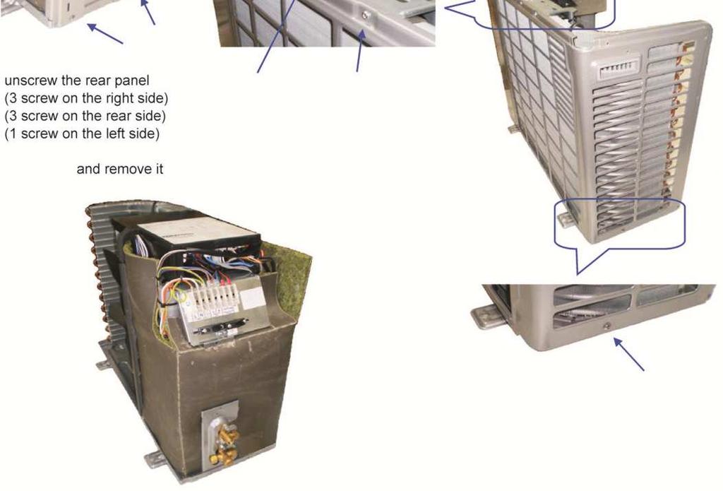
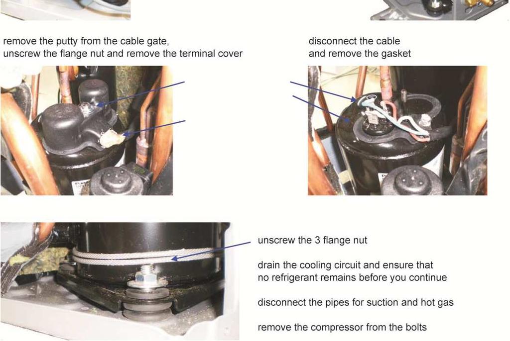
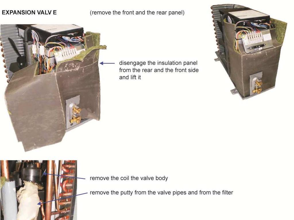
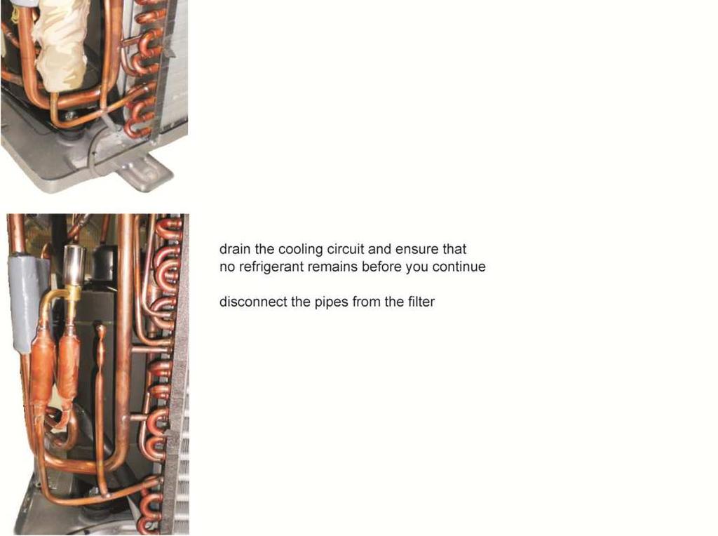
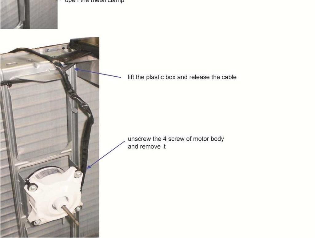
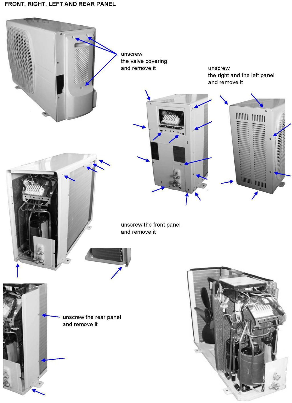
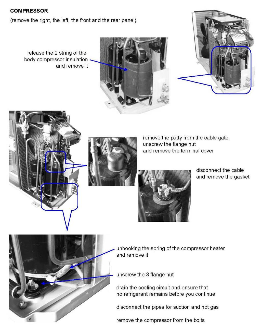
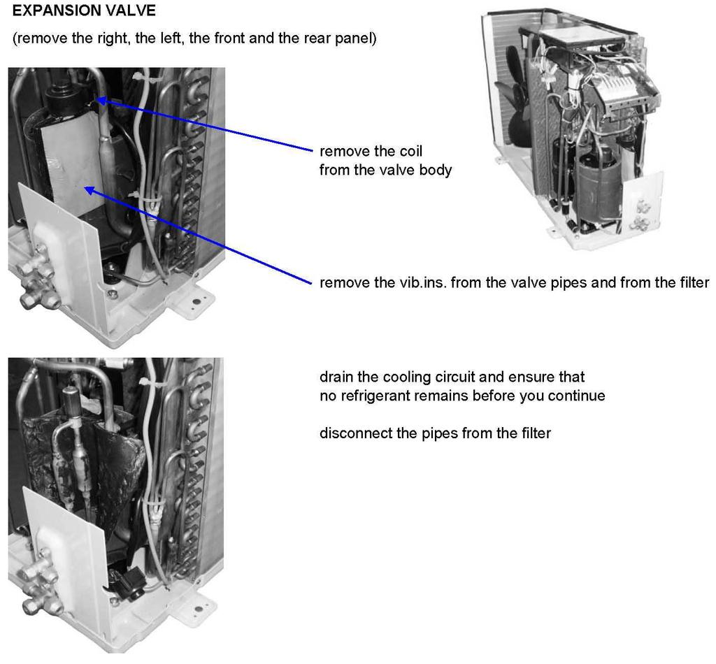
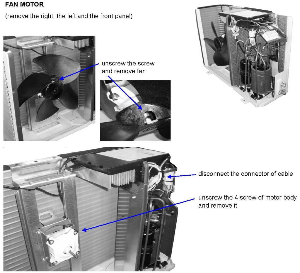
30 13 Component replacement AG-AA10-30
31 AG-AA10-30/40/50
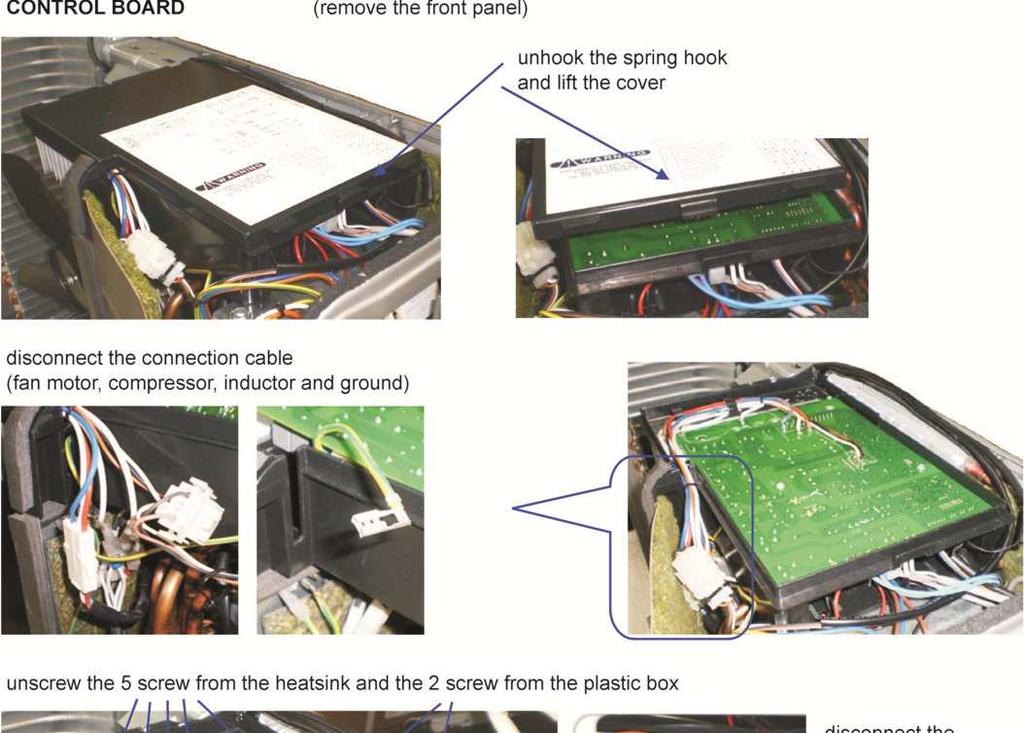
32 AG-AA10-30
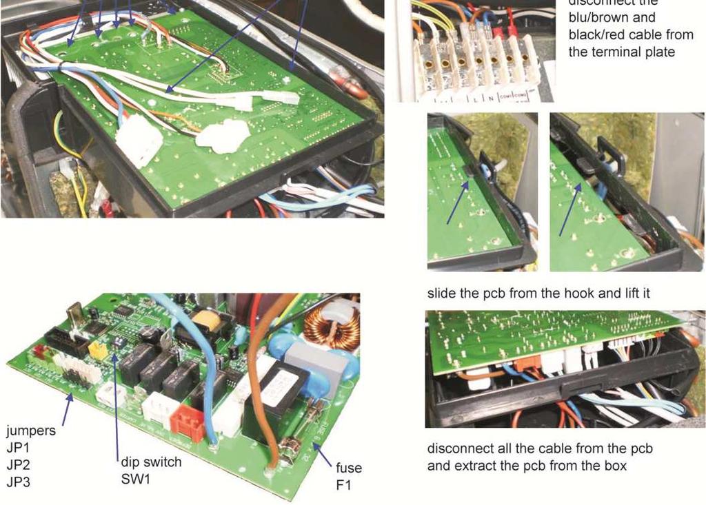
33 AG-AA10-30
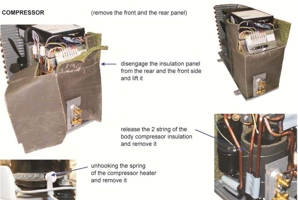
34 AG-AA10-30
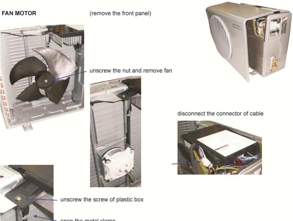
35 AG-AA10-40/50
36 AG-AA10-40/50
37 AG-AA10-40/50
38 AG-AA10-40/50
39 14 Packaging AG-AA : bottom carton box 6: upper right PS shield 2: lower left PS shield 7: carton box 3: lower right PS shield 8: staple 4: polietylene sheet 9: scotch tape 5: upper left PS shield 10: PP band
40 AG-AA10-40/50 1: bottom carton box 6: upper left PS shield 11: PP band 2: lower left PS shield 7: upper right PS shield 3: lower PS shield 8: carton box 4: lower right PS shield 9: staple 5: polietylene sheet 10: scotch tape

41 15 Labels Energy labels AG-AA10-30
42 AG-AA10-40
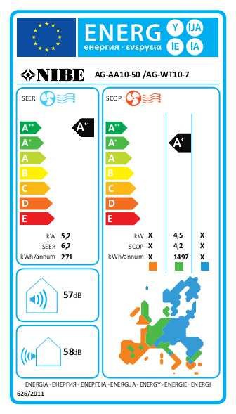
43 AG-AA10-50

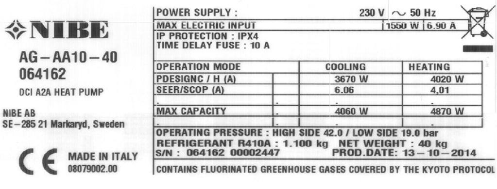
44 Rating labels
TECHNICAL DATA & SERVICE MANUAL. iseries OUTDOOR UNIT: AEI1G 42 EMX AEI1G 50 EMX SPLIT SYSTEM AIR CONDITIONER AEI1G EMX
 TECHNICAL DATA & SERVICE MANUAL iseries OUTDOOR UNIT: AEI1G 42 EMX AEI1G 50 EMX SPLIT SYSTEM AIR CONDITIONER AEI1G 42-50 EMX May 2016 TABLE OF CONTENTS 1 SCOPE... 4 2 DIMENSIONAL DATA AND EXTERIOR APPEARANCE...
TECHNICAL DATA & SERVICE MANUAL
 TECHNICAL DATA & SERVICE MANUAL REVE DCI HPL/SCL 0.8180.615.01 06/2012 Pagina 1 Table of contents Page A SPECIFICATIONS 1) Unit specifications 3 2) Major Component specifications 4 B OPERATING RANGE 6
SPLIT SYSTEM AIR CONDITIONER
 TECHNICAL DATA & SERVICE MANUAL INDOOR UNIT: MRAF99R5IAA MRAF129R5IAA MPAF99R5IAA MPAF129R5IAA SPLIT SYSTEM AIR CONDITIONER Model No. Product Code No. MRAF99R5IAA 38.7104.065 MRAF129R5IAA 38.7104.062 MPAF99R5IAA
Part 3 Troubleshooting
 Part Troubleshooting What is in this part? This part contains the following chapters: Chapter See page Troubleshooting 2 Error Codes: Hydro-box 7 Error Codes: Outdoor Units Error Codes: System Malfunctions
Instructions for the fan motor control system, SILVER C
 Instructions for the fan motor control system, SILVER C 1. General The motor control system is used for controlling the type EC, 0.41-10 kw fan motors in the SILVER C units. The motor control system is
Instructions for the fan motor control system with integrated wiring terminals SILVER C
 Instructions for the fan motor control system with integrated wiring terminals SILVER C 1. General The motor control system is used for controlling the type EC, 0.41-10 kw fan motors in the SILVER C units.
TECHNICAL DATA & SERVICE MANUAL MTF94C5TAA
 TECHNICAL DATA & SERVICE MANUAL MTF94C5TAA 0.8180.472.0 07/2005 Page 1. SPECIFICATIONS 3 1-1 Unit Specifications 3 1-2 Major Component Specifications 4 2. DIMENSIONAL DATA 6 2-1 Unit Dimensions 6 3. ELECTRICAL
TECHNICAL DATA & SERVICE MANUAL
 TECHNICAL DATA & SERVICE MANUAL OUTDOOR UNIT:. TRIAL SPLIT SYSTEM AIR CONDITIONER Model No. Product Code No. 38.7107.102. 0.8180.611.02 09/2012 IMPORTANT! Please read before installation This air conditioning
CMA CONDENSING UNITS FOR OUTDOOR INSTALLATION INSTALLATION AND OPERATION MANUAL
 CMA CONDENSING UNITS FOR OUTDOOR INSTALLATION ECO-FRIENDLY REFRIGERANT GAS INSTALLATION AND OPERATION MANUAL Dear Customer, Thank you for having purchased a FERROLI product. It is the result of many years
SPLIT SYSTEM AIR CONDITIONER
 TECHNICAL DATA & SERVICE MANUAL INDOOR UNIT: MPAFIA0R5IAA SPLIT SYSTEM AIR CONDITIONER Model No. Product Code No. MPAFIA0R5IAA 38.7104.074 0.8180.590.01 10/2012 IMPORTANT! Please read before installation
Advance Split
 Engineering Data Manual Aqu@Scop Advance Split Air-to-Water DC Inverter Split Heat Pumps Models 005, 008, 012 & 014 2 to 16 kw Strength Points Most efficient heating technology with variable speed compressor.
Instructions for the heat exchanger control system SILVER C RX, RECOnomic, sizes 100/120, RECOsorptic, sizes
 Instructions for the heat exchanger control system SILVER C RX, RECOnomic, sizes 100/120, RECOsorptic, sizes 50-120 1 General The heat exchanger control system is a control system for 380 W step motors
Engineering Data Manual
 Engineering Data Manual Residential Split Low Silhuoette LSN DCI Inverter Series Indoor Units LSN 25 DCI LSN 35 DCI LSN 50 DCI LSN 60 DCI LSN 72 DCI Outdoor Units ONG 25 DCI ONG 35 DCI ONG 50 DCI GC 60
A2A, A2W & DHW HEAT PUMP & AIR COND
 A2A, A2W & DHW HEAT PUMP & AIR COND iseries TM OUTDOOR UNITS STANDARD OPERATION LIMIT OPERATION LIMIT -32 C -15 C +43 C +50 C By using state-of-the-art DC Inverter technology, iseries modulates the power
BRAN Residential chillers and heat pumps. Reversible unit, air source for outdoor installation 4,81-27,2 kw <<< BACK INDEX.

SERVICE MANUAL MUZ-DM25VA - E1, ER1, ET1 MUZ-DM35VA - E1, ER1, ET1 OUTDOOR UNIT. No. OBH751. Models HFC R410A
 OUTDOOR UNIT SERVICE MANUAL HFC utilized R410A. Models MUZ-DM25VA - E1, ER1, ET1 MUZ-DM35VA - E1, ER1, ET1 Indoor unit service manual MSZ-DM VA Series (OBH750) CONTENTS 1. TECHNICAL CHANGES 2 2. PART NAMES
RE-PR3-E-27 3-Phase Panel Mount 27kW
 Page 1 of 6 RE-PR3-E-27 3-Phase Panel Mount 27kW Features: Benefits: 0-10Vdc, 0-5Vdc, 4-20mA or manual via potentiometer control input Over temperature protection with auto reset Enclosed panel mounting
Technicians Manual Single Compressor
 Technicians Manual Single Compressor HAC-FF-D WALL PAD Operating Manual Version PCB Version V2.3.5 Version wall pad Version Manual Page 1 Contents 1. Main features 2. Main technical data 3. Wall pad 4.
DC INVERTER SPLIT SYSTEM AIR CONDITIONER
 AIR CONDITIONER TECHNICAL & SERVICE MANUAL KS1872 + C1872 + CL1872 KS2472 + C2472 + CL2472 FILE NO. Destination: North America DC INVERTER SPLIT SYSTEM AIR CONDITIONER Indoor Model No. KS1872 KS2472 Product
Installer manual AG-WL10
 LEK LED CLEAN TIMER OPERATION Installer manual Indoor unit air/air heat pump IHB GB 1637-1 331827 Table of Contents 1 Important information Safety information Read before starting the installation Electrical
Built-on speed controller for GMPM plug fan with permanent magnet motor
 Air Comfort air comfort Centriflow 3D Plug fan GMPM Built-on speed controller» Installation and Operation Built-on speed controller for GMPM plug fan with permanent magnet motor Content Page 1. Introduction...
SERVICE MANUAL MUY-GL24NA - U1. No. OBH733. Models HFC. Revision B: REVISED EDITION-B R410A
 Revision B: MUZ-GL09NA- U8 and MUZ-GL09NAH- U8 have been added. Please void OBH733 REVISED EDITION-A. OUTDOOR INDOOR UNIT UNIT SERVICE MANUAL HFC utilized R410A. OBH733 REVISED EDITION-B Models MUZ-GL09NA
TABLE OF CONTENTS RMXS-E8V1B
 Outdoor Units R-410A RMXS-E8V1B TABLE OF CONTENTS RMXS-E8V1B! 1 Features........................................................... 814 2 Specifications.....................................................
TECHNICAL DATA & SERVICE MANUAL DISEGNO MACCHINA
 TECHNICAL DATA & SERVICE MANUAL DISEGNO MACCHINA ARGO 245C / 3SC Cooling only model ARGO 235H / 3HP Heat pump model 0.8180.405.2 09/2006 Table of contents Page A SPECIFICATIONS 1) Unit specifications 3
TECHNICAL DATA & SERVICE MANUAL
 TECHNICAL DATA & SERVICE MANUAL OUTDOOR UNIT: DUAL SPLIT SYSTEM AIR CONDITIONER Model No. Product Code No. 38.7107.098 38.7107.103 38.7107.106 0.8180.597.03 09/2012 IMPORTANT! Please read before installation
Fast Track Troubleshooting
 Fast Track Troubleshooting Models Covered: RF266AD**/XAA French Door Refrigeration IMPORTANT SAFETY NOTICE For Technicians Only This service data sheet is intended for use by persons having electrical,
TECHNICAL DATA & SERVICE MANUAL DISEGNO MACCHINA
 TECHNICAL DATA & SERVICE MANUAL DISEGNO MACCHINA ARGO 245SCH2O( I ) Cooling only model ARGO 235HPH2O( I ) Heat pump model 0.8180.519.1 11 / 2007 Table of contents Page A SPECIFICATIONS 1) Unit specifications
Epsilon Echos kw. General information Air-Water unit with scroll compressors driven by DC inverter. Unique selling points
 Epsilon Echos+ 5 38 kw General information Air-Water unit with scroll compressors driven by DC inverter Configuration /LN: Low noise unit /HP: Reversible heat pump /LE /HP: Reversible condensing unit Unique
SERVICE MANUAL. No. OBH747 REVISED EDITION-A. Models HFC
 Revision A: MUZ-HM09/12NA- U8, MUZ-HM09/12NA2- U8, MUZ-HM15/18NA- U1, MUZ-HM15/18NA2- U1 and MUZ-HM24NA2- U1 have been added. Please void OBH747. OUTDOOR INDOOR UNIT UNIT SERVICE MANUAL HFC utilized R410A.
SERVICE MANUAL MUZ-FE09NA MUZ-FE09NAH MUZ-FE12NA MUZ-FE12NA1 MUZ-FE12NAH MUZ-FE18NA OUTDOOR UNIT. No. OBH543 REVISED EDITION-F.
 Revision F: The descriptions of the expansion valve coil have been corrected. (10-4.) Some descriptions have been modified. Please void OBH543 REVISED EDITION-E. OUTDOOR UNIT SERVICE MANUAL HFC utilized
Hoffman Controls 759-ECM. Installation & Operating Instructions. Introduction. Installation. Pre-Installation Information/ Instruction
 Hoffman Controls Installation & Operating Instructions Introduction CAUTION Failure to read and understand the accompanying instructions and diagrams prior to energizing the Controller may result in permanent
CMA TECHNICAL MANUAL CONDENSING UNITS FOR OUTDOOR INSTALLATION O L S A F RA N
 E S A RE F R E IG RA N T G TECHNICAL MANUAL -FRIEND Y CONDENSING UNITS FOR OUTDOOR INSTALLATION O L CMA C 2 The manufacturer declines all the responsabilities regarding inaccuracies contained in this manual,
SERVICE MANUAL OUTDOOR UNIT MUZ-FH06NAH MUZ-FH09NAH MUZ-FH06NA MUZ-FH09NA MUZ-FH09NA - 1 MUZ-FH09NAH - 1 MUZ-FH12NA MUZ-FH12NAH
 Revision D: Capacity corrections have been corrected [7-1. 2), 3)]. OBH684 REVISED EDITION-C is void. OUTDOOR UNIT SERVICE MANUAL HFC utilized R410A. OBH684 REVISED EDITION-D Models MUZ-FH06NA MUZ-FH09NA
SERVICE MANUAL MUZ-D30NA / - MUZ-D36NA / - MUY-D30NA / - MUY-D36NA / - OUTDOOR UNIT. No. OBH502. Models HFC. Revision E: REVISED EDITION-E R410A
 Revision E: Capacity corrections have been corrected [7-1. 2), 3)]. OBH502 REVISED EDITION-D is void. OUTDOOR UNIT SERVICE MANUAL HFC utilized R410A. OBH502 REVISED EDITION-E Models MUZ-D30NA / - 1 / -
SERVICE MANUAL MUZ-D30NA MUZ-D30NA- U1 MUZ-D36NA MUZ-D36NA- U1 MUY-D30NA MUY-D36NA OUTDOOR UNIT. No. OBH502. Wireless type Models HFC R410A
 OUTDOOR UNIT SERVICE MANUAL HFC utilized R410A. OBH502 Wireless type Models MUZ-D30NA MUZ-D30NA- U1 MUZ-D36NA MUZ-D36NA- U1 MUY-D30NA MUY-D36NA Indoor unit service manual MSZ-D NA Series (OBH501) MSY-D
AIR-CONDITIONER SERVICE MANUAL
 FILE NO. A90-9608 SERVICE MANUAL AIR-CONDITIONER S SPLIT BUILT-IN DUCT TYPE RAV-362B-PE/ RAV-462B-PE/ SPLIT CEILING TYPE RAV-362C-PE/ RAV-462C-PE/ SPLIT CASSETTE TYPE RAV-362U-PE/ RAV-462U-PE/ PRINTED
SERVICE MANUAL MUFZ-KJ50VE - E1, E2, ER1, ER2, ET1, ET2 MUFZ-KJ35VE OUTDOOR UNIT. No. OBH667. Models HFC
 Revision D: MUFZ-KJ25VE - E2, ER2, ET2, MUFZ- KJ35VE - E2, ER2, ET2 and MUFZ- KJ50VE - E2, ER2, ET2 have been added. Please void OBH667 REVISED EDITION-C. OUTDOOR UNIT SERVICE MANUAL HFC utilized R410A.
Fast Track Troubleshooting
 Fast Track Troubleshooting Models Covered: RS263BBBB/XAA RS263BBSH/XAA RS263BBWP/XAA RS265LBBP/XAA RS265LBWP/XAA SxS Refrigeration Notice: Bulletin on parts change Thermal Fuse to Bi-Metal Publication
TECHNICAL DATA & SERVICE MANUAL
 TECHNICAL DATA & SERVICE MANUAL INDOOR UNIT: CAF97R5IAA CAF98MR5IAA CAF127R5IAA CAF128MR5IAA CAF187R5IAA SPLIT SYSTEM AIR CONDITIONER Model No. CAF97R5IAA CAF127R5IAA CAF187R5IAA CAF98MR5IAA CAF128MR5IAA
Troubleshooting & Reference
 Troubleshooting & Reference Error Code Descriptions Description of Error Codes - 9, 12 MBH code malfunction Error Display Repair Method 1 Storage slug (EEPROM) 2 Indoor PCB malfunction 3 Anti-freezing
TECHNICAL DATA & SERVICE MANUAL
 TECHNICAL DATA & SERVICE MANUAL HEAT PUMP MODELS INDOOR UNIT: MPAF188R5TAA MPAF228R5TAA COOLING MODELS MPAF188C5TAA MPAF228C5TAA SPLIT SYSTEM AIR CONDITIONER Model No. Product Code No. MPAF188R5TAA 38.7104.033
SPECIFICATION GUIDE FLEXAIR. Possibility to add auxiliary heaters: Gas, Electrical Heater, Hot Water Coil Possibility to add Heat Recovery Module
 SPECIFICATION GUIDE FLEXAIR Air-cooled packaged Rooftop unit Cooling only or Heat Pump Nominal cooling capacity: 85 to 234 kw Nominal heating capacity: 83 to 226 kw Possibility to add auxiliary heaters:
DC INVERTER MULTI-SYSTEM AIR CONDITIONER
 TECHNICAL & SERVICE MANUAL OUTDOOR UNIT : CU-3KE19NBU CU-4KE24NBU CU-4KE31NBU DC INVERTER MULTI-SYSTEM AIR CONDITIONER Capacity at 0V 19,100 BTU/h,200 BTU/h 30,600 BTU/h Outdoor Model No. CU-3KE19NBU CU-4KE24NBU
TABLE OF CONTENTS ERSQ-AAY1
 Daikin Altherma High Temperature Outdoor units ERSQ-AAY1 TABLE OF CONTENTS ERSQ-AAY1 1 Features............................................................ 6 2 Specifications......................................................
Fast Track Troubleshooting
 Models Covered: RF266AA**/XAA RF266AB**/XAA RF266**/XAA French Door Refrigeration NOTICE: RF266AA & AB** 01/09 Parts Change: Refer to bulletin. All Water Tank Parts Forced Mode: Press the Pwr Freeze Fridge
Instructions OJ EC-Controller (Translation of the original) BA-ESR_OJ-EC /2013
 BA-ESR_OJ-EC /2013") Instructions OJ EC-Controller (Translation of the original) EN BA-ESR_OJ-EC 1.0 02/2013 Contents Contents... 2 1. Revision Index... 2 2. Introduction... 3 3. Features... 4 4. Installation... 4 5. Operation...
Instructions OJ EC-Controller (Translation of the original) EN BA-ESR_OJ-EC 1.0 02/2013 Contents Contents... 2 1. Revision Index... 2 2. Introduction... 3 3. Features... 4 4. Installation... 4 5. Operation...
Air Conditioning. Technical Data. Pair, Twin, triple, double twin EEDEN RZQ-C
 Air Conditioning Technical Data Pair, Twin, triple, double twin EEDEN-00 RZQ-C TABLE OF CONTENTS RZQ-C Features............................................................. 2 2 Specifications.......................................................
SERVICE MANUAL MUZ-FH25VE MUZ-FH35VE MUZ-FH50VE OUTDOOR UNIT. No. OBH624. Models HFC. Revision A: MUZ-FH50VE- E1 has been added. Please void OBH624.
 SPLIT-TYPE AIR CONDITIONERS Revision A: MUZ-FH50VE- E1 has been added. Please void OBH624. OUTDOOR UNIT SERVICE MANUAL HFC utilized R410A. OBH624 REVISED EDITION-A Models MUZ-FH25VE MUZ-FH35VE MUZ-FH50VE
Lodam Compressor Protection Module. Technical manual. Version 3.0 SE-G1
 Lodam Compressor Protection Module Technical manual Version 3.0 SE-G1 Contents 1. Read this first... 4 1.1. Reading instructions... 4 1.2. User manual... 4 1.3. Safety... 4 2. General... 5 3. Definitions...
DUCTED AIR CONDITIONER. Owner s Manual. KD Series KD24. Kaden Owner s Manual 1
 DUCTED AIR CONDITIONER Owner s Manual KD Series KD24 Kaden Owner s Manual 1 Table of Contents 1. Safety Precautions 4 2. Indoor Unit Parts and Major Functions 6 3. Care and Maintenance 8 4. Troubleshooting
Warning: 230V / 1ph / 50Hz V / 3ph / 50Hz. Remarks: Make sure that you have enough power. (See page 15 Cable table)
") 1 2 Warning: - Do not place your hand or any other objects into the air outlet and fan. It could damage the heat pump and cause injuries; - In case of any abnormality with the heat pump, cut off the power
1 2 Warning: - Do not place your hand or any other objects into the air outlet and fan. It could damage the heat pump and cause injuries; - In case of any abnormality with the heat pump, cut off the power
SERVICE MANUAL MUZ-FH25VE MUZ-FH35VE MUZ-FH50VE OUTDOOR UNIT. No. OBH624 REVISED EDITION-E. Models HFC
 Revision E: MUZ-FH25VE- E4, ER4, ET3, MUZ- FH35VE- E3, ER3, ET3 and MUZ- FH50VE- E2, ER2, ET2 have been added. Please void OBH624 REVISED EDITION-D. OUTDOOR UNIT SERVICE MANUAL HFC utilized R410A. OBH624
Ductless Split Air Conditioner
 Ductless Split Air Conditioner Service Manual Indoor HSU09VHG(DB)-W HSUVHG(DB)-W HSU8VHH(DB)-W HSUVHG(DB)-W Outdoor HSU09VHG(DB)-G HSUVHG(DB)-G HSU8VHH(DB)-G HSUVHG(DB)-G Design may vary by model number.
Installer manual AG-AA10. Air/air heat pump IHB GB AG-AA10-30 AG-AA10-40/50
 -30 Installer manual Air/air heat pump -40/50 IHB GB 1516-1 331554 Table of Contents 1 Important information 2 5 Installation 7 Safety information 2 Model combinations 7 Read before starting the installation
Fast Track Troubleshooting
 Fast Track Troubleshooting Models Covered: RF195AC**/XAA RF197AC**/XAA RF217AC**/XAA IMPORTANT SAFETY NOTICE For Technicians Only This service data sheet is intended for use by persons having electrical,
Blue Box Epsilon Echos +
 Blue Box Epsilon Echos + 5 38 kw General information Air-Water unit with scroll compressors driven by DC inverter Packaged version in 5 sizes Nominal cooling capacity (A35;W7): 6 26 kw Nominal heating
WC Series Vended Washers Troubleshooting, and Fault Codes
 WC Series Vended Washers Troubleshooting, and Codes 1 Common Troubleshooting s Symptom Probable Cause Suggested Remedy 2 Machine does not start Machine will not accept and count coins Door does not lock
Unit Controller (UC8) Quick Reference Operation and Fault Diagnosis
 Quick Reference Operation and Fault Diagnosis") Unit Controller (UC8) Quick Reference Operation and Fault Diagnosis (To be read in conjunction with labels TZ243 (Air-to-Air) & TZ245 (Water-to-Air) Date: 20 October 2015 Issue: 1 Index 1. Introduction...
Unit Controller (UC8) Quick Reference Operation and Fault Diagnosis (To be read in conjunction with labels TZ243 (Air-to-Air) & TZ245 (Water-to-Air) Date: 20 October 2015 Issue: 1 Index 1. Introduction...
DC INVERTER SPLIT SYSTEM AIR CONDITIONER
 TECHNICAL & SERVICE MANUAL XHS1271 & PNR-XS1872 + CH1271 XHS1872 & PNR-XS1872 + CH1872 FILE NO. Destination: North America DC INVERTER SPLIT SYSTEM AIR CONDITIONER Indoor Model No. Body (Panel) XHS1271
EREBA ACCESS. Easy and fast installation Hydronic module available Compact, reliable and efficient USE RANGE CONFORMITY
 Easy and fast installation Hydronic module available Compact, reliable and efficient Nominal cooling capacity : 8-40 kw Nominal heating capacity : 17-40 kw 50 410A Cooling or heating USE The air-to-water
Split inverter air-to-water heat pump CERTIFIED BY CERTITA. option 30/35-40/45
 Plug & Heat heat pump Quick and easy to install For new homes or boiler backup operation 50 HFC R410A CERTIFIED BY CERTITA Heating capacity: 5.5 to 22 kw option CERTIFIED BY CERTITA 30/35-40/45 USE The
Air Conditioning. Technical Data EEDEN AZQS-BV1
 Air Conditioning Technical Data EEDEN14-131 AZQS-BV1 TABLE OF CONTENTS AZQS-BV1 1 Features............................................................. 2 2 Specifications.......................................................
DYNACIAT LGN. Description. Split system Water chillers. High energy efficiency Compact and quiet Scroll compressors Brazed-plate heat exchangers
 High energy efficiency Compact and quiet Scroll compressors Brazed-plate heat exchangers Self-adjusting electronic control Cooling capacity: 35 to 700 kw 410A Cooling Operation DYNACIAT - DYNACIAT POWER
Refrigeration Controller Operator s Manual (HRC) PO Box 6183 Kennewick, WA
 PO Box 6183 Kennewick, WA") Refrigeration Controller Operator s Manual (HRC) PO Box 6183 Kennewick, WA 99336 www.jmcvr.com 1-509-586-9893 Table of Contents TABLE OF FIGURES...1 OVERVIEW OF THE HRC CAPABILITIES...2 INSTALLATION AND
Refrigeration Controller Operator s Manual (HRC) PO Box 6183 Kennewick, WA 99336 www.jmcvr.com 1-509-586-9893 Table of Contents TABLE OF FIGURES...1 OVERVIEW OF THE HRC CAPABILITIES...2 INSTALLATION AND
WALL MOUNTED type SPLIT TYPE ROOM AIR CONDITIONER. Models CONTENTS
 SPLIT TYPE ROOM AIR CONDITIONER WALL MOUNTED type Models Indoor unit ASY9USCCW ASY9USCCW ASY12USCCW Outdoor unit AOY9USCC AOY9UFCC AOY12USCC CONTENTS SPECIFICATIONS.................. 1 OUTLINE AND DIMENSIONS.........
Air Conditioning. Technical Data EEDEN RZQG-L8/7V1
 Air Conditioning Technical Data EEDEN14-100 RZQG-L8/7V1 Outdoor Unit RZQG-L8/7V1 TABLE OF CONTENTS RZQG-L8/7V1 1 Features............................................................. 2 2 Specifications.......................................................
TECHNICAL DATA & SERVICE MANUAL
 TECHNICAL DATA & SERVICE MANUAL OUTDOOR UNIT: GRF188R5TAA GRF228R5TAA GRF228R7TAA SPLIT SYSTEM AIR CONDITIONER Model No. Product Code No. GRF188R5TAA 38.7107.083 GRF228R5TAA 38.7107.084 GRF228R7TAA 38.7107.085
WALL MOUNTED type SPLIT TYPE ROOM AIR CONDITIONER CONTENTS. Models
 SPLIT TYPE ROOM AIR CONDITIONER WALL MOUNTED type Models Indoor unit ASY9USCCW ASY9USCCW ASY12USCCW Outdoor unit AOY9USCC AOY9UFCC AOY12USCC CONTENTS SPECIFICATIONS.................. 1 OUTLINE AND DIMENSIONS.........
Zeta Rev LN HP Prochill Bluebox Print Date: 07/17/2017
 Zeta Rev LN HP 10.2 Configured unit accessories 1PS - One user-side pump with tank LN - Low noise RG - Condensation control with fan speed regulator CSP - Set point compensation depending on external air
Technical Manual. Multi Split Trio Quattro DCI REFRIGERANT R410A HEAT PUMP
 Technical Manual Multi Split Trio Quattro DCI Indoor Units WNG 9 DCI INV WNG 12 DCI INV WNG 18 DCI INV ECF 9 DCI INV ECF 12 DCI INV ECF 18 DCI INV PXD 9 DCI INV PXD 12 DCI INV PXD 18 DCI INV LS 35 DCI
DC INVERTER MULTI-SYSTEM AIR CONDITIONER
 TECHNICAL & SERVICE MANUAL OUTDOOR UNIT : CLM97 CLM7 CLM7 FILE NO. Destination: North America DC INVERTER MULTI-SYSTEM AIR CONDITIONER Capacity at 0V 9,700 BTU/h,00 BTU/h 0,600 BTU/h Outdoor Model No.
Product Data INDUSTRY LEADING FEATURES / BENEFITS
 8MGR Multi-zone Outdoor Unit Ductless System Sizes 18, 24, 0, 6 and 48 Fig. 1 18K Fig. 2 24K and 0K Product Data INDUSTRY LEADING FEATURES / BENEFITS A competitively priced and creative solution to design
DESIGN & TECHNICAL MANUAL
 AIR CONDITIONER Wall mounted type DESIGN & TECHNICAL MANUAL INDOOR ASYG07KGTA ASYG09KGTA ASYG12KGTA ASYG14KGTA OUTDOOR AOYG07KGCA AOYG09KGCA AOYG12KGCA AOYG14KGCA DR_AS049EF_02 2017.10.11 Notices: Product
AIR COOLED HEAT PUMP FOR OUTDOOR INSTALLATION FROM 4,2 TO 35,1 kw
 COMFORT HEAT PUMPS AIR COOLED HEAT PUMP FOR OUTDOOR INSTALLATION FROM 4,2 TO 35,1 kw climaveneta.com COMFORT HEAT PUMPS PERFECT COMFORT AND MAXIMUM EFFICIENCY Air to water heat pump for outdoor installation,
OPERATION INSTRUCTIONS DEMAND DEFROST CONTROL BOARD MODEL FOR USE WITH MODELS: AFFINITY, ECHELON, ACCLIMATE HEAT PUMP SERIES
 OPERATION INSTRUCTIONS DEMAND DEFROST CONTROL BOARD MODEL 500644 FOR USE WITH MODELS: AFFINITY, ECHELON, ACCLIMATE HEAT PUMP SERIES A047-001 FIGURE 1: Demand Defrost Control Module ANTI-SHORT CYCLE DELAY
Miraco MISR REFRIGERATION & AIR CONDITIONING MFG. CO.
 MISR REFRIGERATION & AIR CONDITIONING MFG. CO. COOL EER HEAT COP 0V ~ 50Hz 1Ph Inverter High Wall Split Systems For Energy Saving Heat Pump 1K - 18K - 4K DC Inverter R-410A Inverter Technology R-410A HFC
OWNER S MANUAL. R 410A Ductless Split System Air Conditioner and Heat Pump
 R 410A Ductless Split System Air Conditioner and Heat Pump Models DLC4(A/H) Outdoor Unit, DLF4(A/H) Indoor Unit Sizes 9K, 12K, 18K, 24K, 30K and 36K Please read the operating instructions and safety precautions
Unico Presentation. Introducing
 Introducing Combines all the efficiencies and performance of inverter technology with all the features and benefits of The Unico System Made in conjunction with Argoclima Group is a European leader in
TECHNICAL DATA & SERVICE MANUAL SPLIT SYSTEM AIR CONDITIONER INDOOR UNIT: CAF94R5 CAF124R5 CAF94R
 TECHNICAL DATA & SERVICE MANUAL INDOOR UNIT: CAF94R5 CAF124R5 SPLIT SYSTEM AIR CONDITIONER Model No. Product Code No. CAF94R5 387106979 CAF124R5 387106980 0.8180.361.0 07/2005 IMPORTANT! Please read before
Product Data INDUSTRY LEADING FEATURES / BENEFITS
 8MGR Multi-zone Outdoor Unit Ductless System Sizes 18, 24, 0, 6 and 48 Fig. 1 18K Fig. 2 24K and 0K Product Data INDUSTRY LEADING FEATURES / BENEFITS A competitively priced and creative solution to design
PHRIE / PHIE InvERTER monoblock air To water HEaT PumP medium TEmPERaTuRE
 TEcHnIcal InsTRucTIons PHRIE / PHIE InvERTER monoblock air To water HEaT PumP medium TEmPERaTuRE PHRIE 095 PHRIE 1 PHIE 095 PHIE 1 PHRIE 155 PHRIE 157 PHRIE 175 PHRIE 177 PHRIE 195 PHRIE 197 PHRIE 7 PHRIE
WALL MOUNTED type SPLIT TYPE ROOM AIR CONDITIONER CONTENTS. Models
 SPLIT TYPE ROOM AIR CONDITIONER WALL MOUNTED type Models Indoor unit ASY9USCCW ASY9USCCW ASY12USCCW Outdoor unit AOY9USCC AOY9UFCC AOY12USCC CONTENTS SPECIFICATIONS................................... 1
SERVICE MANUAL MUZ-GB50VA - E1 MUZ-GB50VA - E2 MUZ-GB50VA - E3 OUTDOOR UNIT. No. OB455. Models HFC
 Revision G: Errors in TROUBLESHOOTING have been corrected. Please void OB455 REVISED EDITION-F. OUTDOOR UNIT SERVICE MANUAL HFC utilized R410A. OB455 REVISED EDITION-G Models MUZ-GB50VA - E1 MUZ-GB50VA
RCS Residential Control Systems Inc.
 RCS Residential Control Systems Inc. Model TZ16 Z-Wave Communicating Thermostat with Rev P HVAC Control Unit INSTALLATION AND OPERATION MANUAL DCN: 141-00882 Rev 02 5/18/06 This manual applies to the following
Instructions for the hand-held micro terminal of the fan motor control system, TBLZ-2-75 SILVER C
 Instructions for the hand-held micro terminal of the fan motor control system, TBLZ-2-75 SILVER C 1. General The hand-held micro terminal is used for setting the motor parameters of the SILVER C. 2. Installation
SERVICE INSTRUCTION R410A. WALL MOUNTEDtype SPLIT TYPE ROOM AIR CONDITIONER INVERTER. Models Indoor unit Outdoor unit AO* R09LECN AO* R12LECN
 SERVICE INSTRUCTION SPLIT TYPE ROOM AIR CONDITIONER WALL MOUNTEDtype INVERTER Models Indoor unit Outdoor unit AS* A09LEC AS* A12LEC AO* R09LECN AO* R12LECN R410A CONTENTS 1. DESCRIPTION OF EACH CONTROL
SERVICE MANUAL MUZ-EF25VE MUZ-EF25VEH MUZ-EF35VE MUZ-EF35VEH MUZ-EF42VE MUZ-EF50VE. No. OBH590 REVISED EDITION-F. Models HFC
 Revision F: The descriptions of the expansion valve coil have been corrected. (11-4.) Please void OBH590 REVISED EDITION-E. OUTDOOR INDOOR UNIT UNIT SERVICE MANUAL HFC utilized R410A. OBH590 REVISED EDITION-F
SPLIT TYPE ROOM AIR CONDITIONER. WALL MOUNTEDtype INVERTER. Models Indoor unit Outdoor unit AOU 9RLFW1 AOU12RLFW1 ASU 9RLF1 ASU12RLF1 R410A
 SERVICE INSTRUCTION SPLIT TYPE ROOM AIR CONDITIONER WALL MOUNTEDtype INVERTER Models Indoor unit Outdoor unit ASU 9RLF ASURLF AOU 9RLFW AOURLFW R40A CONTENTS. DESCRIPTION OF EACH CONTROL OPERATION. COOLING
Side-by-side combined refrigerator-freezer
 REPAIR INSTTRUCTTI I IONS Side-by-side combined refrigerator-freezer 1 SAFETY... 2 4.1 Electronic controller... 8 1.1 Safety instructions... 2 1.2 Repair instructions... 2 2 INSTALLATION... 3 3 OPERATION...
Ductless Split Air Conditioner
 Ductless Split Air Conditioner Service Manual Indoor AW09ESVHA AWESVHA AW8ESVHA AWESVHA Outdoor U09ESVHA UESVHA U8ESVHA UESVHA Design may vary by model number. Please read this manual before using the
USER-MANUAL Tamson Cool Cube Immersion Cooler
 USER-MANUAL Tamson Cool Cube Immersion Cooler Page 1/14 1 SAFETY AND WARNINGS... 3 2 WARRANTY... 3 3 DISCLAIMER... 3 4 PRECAUTIONS AND HAZARDS... 4 5 INSTALLATION... 4 5.1 IMPORTANT... 4 6 USE... 5 7 WHAT
Freightliner Refrigerator Troubleshooting Guide For (TJ18F) (TJ22F) (TJ18FP3)
 (TJ22F) (TJ18FP3)") www.dometic.com Freightliner Refrigerator Troubleshooting Guide For Before initiating troubleshooting, the following equipment is recommended: Multimeter, 20 gauge (min) wires to use as jumpers, and 12Vdc
www.dometic.com Freightliner Refrigerator Troubleshooting Guide For Before initiating troubleshooting, the following equipment is recommended: Multimeter, 20 gauge (min) wires to use as jumpers, and 12Vdc
R410A. WALL MOUNTEDtype INVERTER SPLIT TYPE ROOM AIR CONDITIONER. Models Indoor unit Outdoor unit AO*G09LTCN AO*G12LTCN AO*G14LTCN
 SERVICE INSTRUCTION SPLIT TYPE ROOM AIR CONDITIONER WALL MOUNTEDtype INVERTER Models Indoor unit Outdoor unit AS*G09LTCB AS*GLTCB AS*G4LTCB AO*G09LTCN AO*GLTCN AO*G4LTCN R40A CONTENTS. DESCRIPTION OF EACH
Fast Track Troubleshooting
 Fast Track Troubleshooting Models Covered: RS267TDBP/XAA RS267TDPN/XAA RS267TDRS/XAA RS267TDWP/XAA NOTICE: RS267TD PN & RS Colors Parts Change: Refer to bulletin. Door Handle Parts Change IMPORTANT SAFETY
SERVICE MANUAL MSZ-GL06NA - U1 MSZ-GL09NA - U1 MSZ-GL12NA - U1 MSZ-GL15NA - U1 MSZ-GL18NA - U1 MSZ-GL24NA - U1
 Revision B: 3. SPECIFICATION has been corrected. Please void OBH732 REVISED EDITION-A. INDOOR UNIT SERVICE MANUAL. OBH732 REVISED EDITION-B Models MSZ-GL06NA - U1 MSZ-GL09NA - U1 MSZ-GL12NA - U1 MSZ-GL15NA
USE AND MAINTENANCE MANUAL
 USE AND MAINTENANCE MANUAL FSC25 PAY ATTENTION: when switch over from AUTomatic to CONTinuous functioning using front switch, wait at least one second in position OFF (0); otherwise it s possible to cause
Air Conditioning. Technical Data EEDEN RZQSG-L(8)Y1
Y1") Air Conditioning Technical Data EEDEN3-00 RZQSG-L(8)Y Outdoor Unit RZQSG-L(8)Y TABLE OF CONTENTS RZQSG-L(8)Y Features............................................................. 2 2 Specifications.......................................................
Air Conditioning Technical Data EEDEN3-00 RZQSG-L(8)Y Outdoor Unit RZQSG-L(8)Y TABLE OF CONTENTS RZQSG-L(8)Y Features............................................................. 2 2 Specifications.......................................................
Air Conditioning Technical Data RZASG-MV1
 Air Conditioning Technical Data RZASG-MV1 Outdoor Unit RZASG-MV1 TABLE OF CONTENTS RZASG-MV1 1 Features............................................................. 2 2 Specifications.......................................................
Owner s Manual Super-Slim Four-Way Cassette
 CASSETTE- TYPE AIR CONDITIONER Owner s Manual Super-Slim Four-Way Cassette IMPORTANT NOTE: Read this manual carefully before installing or operating your new air conditioning unit. Make sure to save this
SERVICE MANUAL MSZ-GE22VA - E1 MSZ-GE25VA - E1 MSZ-GE35VA - E1 MSZ-GE42VA - E1 MSZ-GE50VA - E1 MSZ-GE60VA - E1 MSZ-GE71VA - E1 INDOOR UNIT. No.
 SPLIT-TYPE AIR CONDITIONERS Revision E: Detail of the indoor fan speed control in COOL or DRY operation has been added (9-1.3, 9-2.3). Please void OBH515 REVISED EDITION-D. INDOOR UNIT SERVICE MANUAL.