INSTALLATION, OPERATION AND MAINTENANCE MANUAL FOR G-TRAC2 INDIRECT FIRED HEATING CONTROLLER USA HEAD OFFICE AND FACTORY
|
|
|
- Tracey Wood
- 5 years ago
- Views:
Transcription
 287-4774 Fx: 888-364-2727 USA HEAD OFFICE AND FACTORY 32050 W.")

1 INSTALLATION, OPERATION AND MAINTENANCE MANUAL FOR G-TRAC2 INDIRECT FIRED HEATING CONTROLLER UNIT MODEL NO. UNIT SERIAL NO. SERVICED BY: TEL. NO: CANADIAN HEAD OFFICE AND FACTORY 1401 HASTINGS CRES. SE CALGARY, ALBERTA T2G 4C8 Ph: (403) Fx: USA HEAD OFFICE AND FACTORY W. 83 rd STREET DESOTO, KANSAS Ph: (913) Fx: (913) CANADIAN EASTERN FACTORY 1175 TWINNEY DRIVE NEWMARKET, ONTARIO L3Y 5V7 Ph: (905) Fx: (905) SALES OFFICES ACROSS CANADA AND USA Retain instructions with unit and maintain in a legible condition. Please give model number and serial number when contacting factory for information and/or parts. IOM 26 Mar 99 R6
2 TABLE OF CONTENTS I. APPLICATION... 6 II. SERVICE... 6 III. RESET DISCHARGE AIR TEMPERATURE... 6 IV. GENERAL DESCRIPTION... 6 OPERATION... 6 BASIC FEATURES... 7 V. WIRING... 7 VI. SYSTEM TIMINGS... 8 VII. BLOWER AIR AND GAS MODULATION... 8 VIII. DIP SWITCHES... 8 DIP SWITCH BLOCK A... 8 DIP SWITCH BLOCK B FUEL CURVES/AIR CURVES... 9 GAS CURVES... 9 AIR CURVES... 9 DIPSWITCH BLOCK C LOW LIMIT, PI, CTRAC, 010 VDC CONTROL... 9 IX. POTS X. STATUS LIGHTS LED 1 BURNER PRE PURGE LED 2 HEAT REQUIRED LED 3 LOCKOUT FLAME FAILURE OR LOW LIMIT LED 4 BURNER XI. AUTO BYPASS LOW LIMIT XII. DAY AND NIGHT OPERATING STRATEGIES SUPPLY FAN, DAMPER AND HEAT OPERATION Standard Supply Fan Function (Temperature Priority Program) Day/Night General Description of Fan/Damper Operation Fan/Damper During Day (Terminal K No Power) Dipswitch A Fan Damper at Night (Terminal K Powered) XIII. BASIC BURNER OPERATION THE BASIC BURNER OPERATING SCHEME IS AS FOLLOWS: HEAT REQUIRED LED ON PRE PURGE LIGHT XIV. TEMPERATURE CONTROL GENERAL OVERVIEW XV. THE MASTER SET POINT XVI. INDUCED VOLTAGE ON REMOTE CONTROL WIRING XVII. NIGHT HEAT THERMOSTATS IOM 26 2 of 42 Mar 99 R6
3 XVIII. ROOM RESET THERMOSTAT OPTIONS MODULATING ROOM RESET (CONTINUOUS BLOWER OPERATION ONLY) CALCULATED DISCHARGE TABLE FOR ROOM AND AMBIENT RESET MULTIPLE ROOM SENSORS BMS RESET (CONTINUOUS BLOWER ONLY) BMS RESET FROM VOLTAGE APPLIED TO + AND BMS CALIBRATION AMBIENT RESET (DAY MODE ONLY REQUIRES DIPSWITCH A 2 TO BE ON) MAKE/BREAK RESETS AND OVERRIDES OR and V Override (Day Only) "X" and "Z" Override (Day and night operation) Linear Ambient Reset (During day and night) Room Control with Intermittent Blower (During night) DIRECT CONTROL 0 10 VDC (CTRAC, METASYS) FOR DIRECT C TRAC CONTROL OF THE GTRAC 2... ERROR! BOOKMARK NOT DEFINED. FOR DIRECT 0 10 VDC CONTROL XIX. CALCULATED SET POINT READOUT (BASE PLUS CALCULATED) XX. DISCHARGE TEMPERATURE READOUT XXI. DISCHARGE SENSOR READOUTS, CALIBRATION, ETC TE6100 RESISTANCE S TE6000 DISCHARGE SENSOR SELF TEST SENSOR RESISTANCE CHART FOR TE AND TE DISCHARGE SENSOR CALIBRATION DISCHARGE SET POINT CALIBRATION Johnson Set Point Built In Set Point ROOM SENSOR CALIBRATION BMS CALIBRATION AND SET UP XXII. SET UP SHEET XXIII. BURNER SET UP OPERATOR CONTROL RULES MANUAL SERVICE MODE COMBUSTION SET UP PROPANE GAS INLET/MANIFOLD PRESSURE SETTINGS XIV. SPECIAL SERVICE NOTES ON BOARD FUSE LOW LIMIT LOCKOUTS FAILED OPERATION OR SOLID STATE CONTROL CONTACTS BY OTHERS AIR BALANCING (REFER TO NEXT ITEM) COLD DISCHARGE TEMPERATURE IN COLD WEATHER IGNITION PROBLEMS REGULATOR GAS PRESSURE RESPONSES PILOT SENSING PROBLEMS SMELL FROM FLUE (PRODUCTS OF COMBUSTION) WATER AND ICE FROM COMBUSTION BURNER PULSING, BACKFIRING, EXPLODING, NOISY FIRE WITHOUT COMBUSTION FAN HEAT LOCKED ON SLAVE TO C TRAC IOM 26 3 of 42 Mar 99 R6
4 PREPURGE LIGHT STAYS AT DAMPER MOVING STATUS REPLACING A IN THE FIELD CHANGING GAS OR AIR OPERATOR ON XXV. MISCELLANEOUS NOTES IOM 26 4 of 42 Mar 99 R6

5 IOM 26 5 of 42 Mar 99 R6
6 A Report any errors, omissions, etc. to Engineered Air Calgary Service at (403) or FAX (403) Warranty will only be honored when a qualified HVAC service person, who has received training on the is employed for service and troubleshooting. If further information is required please contact the nearest Engineered Air office. I. APPLICATION The is designed to control larger capacity high turndown DG indirect fired burners applied to heating, vent and/or MUA applications. II. SERVICE Do not adjust pots or dip switches unless you are familiar with operation, effect, and how to return to correct setting. Just noting settings will not allow return to the exact position on some pots, which require special instruments to set. Before servicing, the technician should be familiar with the following points in this guide: The GTRAC 2 internal fuse should be checked if the control is dead when 24 VAC is on "T1 and T2". (Section XXIII) System Timings (Section V) Basic Operation (Section IV) Status Lights (Section IX) Temperature Readout (Section XIX) Calculated Set Point (Section XVIII) Auto Bypass Low Limit (Section X) III. RESET DISCHARGE AIR TEMPERATURE Some 's accept reset signals from other devices that can reset discharge air temperature. Refer to the unit wiring diagram and GTRAC 2 label, to determine if room thermostats, return thermostats, remote set points, ambient resets, building management resets (BMS), etc., are in use. If used, refer to appropriate reset information in this guide. IV. GENERAL DESCRIPTION The is a programmed logic controller designed for use with the Engineered Air DG series heaters. This control package provides temperature, supply blower, and burner control. The eliminates the mechanical linkages between the combustion air and gas actuator by using direct drive floating point. The is not intended to be retrofitted on jobs with the older G TRAC/V9055 gas valve combination. Operation On start up the opens the dampers and starts the blower after a time delay. If there were a call for heat the combustion blower would operate at full air to purge the heat exchanger. After the heat exchanger is purged, the air and gas operators move to light off position. The closes contacts to activate a flame supervision device. This device activates the ignition, supervises the pilot flame and main flame. After the main flame is activated a feedback signal to G TRAC2 terminal 3 allows the to modulate the heat as required maintaining the discharge temperature set point. If there is an optional reset device attached, it electronically modifies the discharge air set point. The calculated set point IOM 26 6 of 42 Mar 99 R6
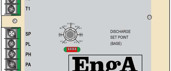
7 value can be read at the terminals provided (See Section XVIII). The will modulate/cycle the burner as needed to maintain discharge air temperatures. Basic Features 1. Standard service and testing features such as status indicating LED s, service pot, and temperature test points. 2. Proportional and Integral (PI) discharge air temperature control. 3. Built in discharge set point with a 55 to 100ºF setting range (or optional remote set point). 4. Supports one of the optional resets (discharge set point reset) from the following list: Room Sensing (resistive) Ambient Sensing (resistive) 0 10 Vdc 4 20 ma 5. Built in auto bypass low limit (can be switched off, Section X). 6. Alarm output contacts (AL). The contacts provide low limit and flame failure annunciation. (Note the Low Limit bypass can be switched off, Section X.) 7. Has input terminals for the fan switch, heat switch, and time clock contact, usually remote controlled by a remote panel, DDC controls etc. Other input terminals are internally controlled. (E.g. AS, 3, Feedback pots). 8. Intermittent night blower (and optional damper) operation. Unit discharges at an adjustable elevated discharge temperature whenever the room calls. GTRAC 2 has no night setback set point; therefore, a second night stat is required for a lower set point. 9. Compatible with 0 10 VDC direct control signal. Optical isolation on the digital and BMS inputs (+ and ). V. WIRING Power supply = amps. The terminals T1 and T2 require a separate 24 VAC, 20 VA class 2 ungrounded isolation transformer supplying power to only T1 and T2. Terminal N should be wired to the neutral which is common to the same grounded power source supplying power to terminals HS, FS, K, and AS. All remote wiring less than 50 feet long installed in clean electrical environments and attached to terminals M, P, Q, U, X, Y, V, Z and OR should be a minimum of 22 ga twisted pair wire. For longer runs and electrically noisy installations, the use of a minimum 20 gauge shielded wire is recommended. (Shield to be grounded at GTRAC 2 end only.) The main digital outputs (damper, supply blower, combustion blower, flame relay, pilot valve, and lockout alarm) are rated at 4 amps. Digital outputs CA, CG, OA and OG are rated at 1 amp at 24 VAC. IOM 26 7 of 42 Mar 99 R6
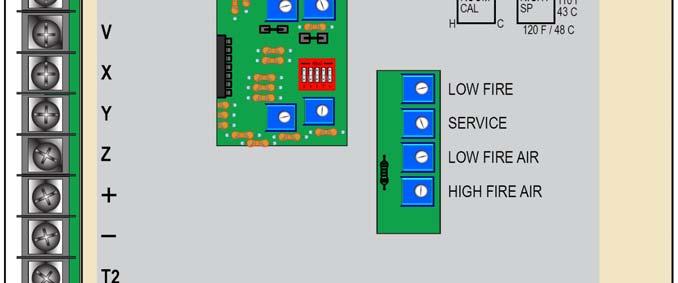
8 VI. SYSTEM TIMINGS Pre purge Maintained purge Supply fan start delay (damper open time) Heat exchanger warm up time Burner cool down time Heat exchanger cool down time Flame fail Flame fail light Auto Low limit Bypass (from blower start) 75 seconds at 85% opening 5 minutes 64 seconds 64 seconds 60 seconds 1 min (except on low limit failure) Usually 15 seconds (it is set by flame relay) 90 seconds from ignition command 5 minutes 30 second anti cycle timer VII. BLOWER AIR AND GAS MODULATION As a gas valve or damper opens or closes, the flow through the device changes in a non linear fashion. This varying flow rate normally creates set up and operating problems. Advanced technology in the corrects these issues. The monitors both the gas and air operator positions and calculates the corrected flow rates. Modulating adjustments of the gas and air are based on flow rates through gas valves and dampers, not on degrees of control rotation that other systems use. This allows the to maintain an accurate set up throughout the complete combustion range. Refer to Section XXII for set up procedures and Section XXIII for information changing operators or s in the field. VIII. DIP SWITCHES The has three dip switch blocks (each block has 5 switches). The individual switches are numbered from 1 through 5 and are used for the following purposes: Dip Switch Block A Is accessible from the large opening on the G TRAC label. Switch 1 of Block A is located on the right hand side. The switches are used to activate the following functions: A 1 BMS reset (0 10 VDC, 0 10 VDC, 4 20 ma). A 2 Ambient reset. A 3 Room reset. A 4 Supply Fan configuration switch. (At start up and during operation "ON" maintains airflow as a priority, to pressurize space. "OFF the discharge temperature has priority). If the airflow has priority then the supply fan doesn t shut down if the discharge temperature is too cold. (Often selected as per day/night configuration chart.) This statement applies to the GTRAC 2 control starting up from a cold start. A 5 Service mode If this switch is on the Heat Required light will be flashing, erratically, indicating the control is in a service mode. IOM 26 8 of 42 Mar 99 R6
9 Dip switch Block B Fuel Curves/Air Curves The GTRAC 2 has built in air to fuel ratio curves. The combination of these curves provides 16 possible settings. The curves are selected by turning dipswitches on or off. These dipswitches are located in a slot below the set point knob on the front of the control. Dipswitches 1 and 4, on block A and B, adjust the gas valve curve; dipswitches two and five adjust the combustion air curve. There is a label attached to the unit indicating the factory dipswitch settings. The correct curves for a particular burner will vary based on the gas valve, air shutter, and combustion air blower and unit size. If there are problems with condensate forming in the flue, the burner can be set up to reduce the amount of condensate formed. This will require the burner to operate with extra combustion air (higher O 2 ) in the mid to low fire range. Increasing the amount of combustion air distributes the water vapor, formed during combustion, over a larger volume of flue gases. This dilutes the concentration and lowers the dew point temperature. Note however, that increasing the amount of excess air too much will reduce the burner efficiency, slightly. Following are curve guides for setting up air/fuel mixtures. Dipswitches 1 and 4 set gas valve curves. Dipswitches 2 and 5 set air damper curves. GAS CURVES Gas Dip switch 1 Dip switch 4 Characteristics Curve 1 OFF OFF Undersized valve or high efficiency application. Lower O 2 in mid range. 2 OFF ON Normal Setting 3 ON OFF Oversized gas valve or condensate reduction. More O 2 in midrange. 4 ON ON Even more O 2 in low and mid range. * * On versions manufactured after May 12, AIR CURVES Air Curve Dipswitch 2 Dipswitch 5 Characteristics 1 OFF OFF Rich (Lower O 2 in mid range). 2 ON OFF Normal Setting 3 OFF ON Lean (More O 2 in mid range). 4 ON ON Lean S curve Dipswitch Block C Low Limit, PI, CTRAC, 010 VDC Control This dip switch block is located: G TRAC 2.1 near the top on the back of the board. G TRAC 2.2 through the small slot at the very top of the panel front. The controller must be turned over to access these switches. This dipswitch block provides low limit enable or disable, and control choices of Normal PI, CTRAC PI or Direct 0 10 VDC Control (such as from a BMS). XXX Switch position does not affect description in ACTION box. IOM 26 9 of 42 Mar 99 R6
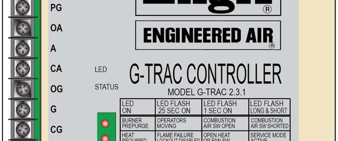
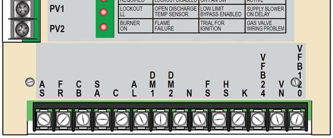
10 SW1 SW2 SW3 SW4 SW5 ACTIONS XXX XXX XXX XXX ON Low limit active. * XXX XXX XXX XXX OFF Low limit disabled. * OFF ON OFF OFF XXX NORMAL OPERATION (PI control). (No BMS on C TRAC direct control but may be reset control) OFF OFF ON ON *** Direct C TRAC3 control (reduced integral control). ON OFF ON ON Direct BMS 010 VDC control (proportional control only). * Set up sheet Section XX. If the low limit is required a discharge sensor must be connected to terminals Q and U and jumper U to S. If the low limit is not required jumper terminals Q to U. When using direct control, by C TRAC on BMS terminal S must be connected to terminal U. Dipswitch A 1 must be in the off position (BMS reset disabled). IX. POTS The has 10 adjustable trim pots. POT NAME APPLICATION PAGE # DSEN CAL Discharge sensor calibration. 30 DSP CAL Discharge set point calibration. 30 BMS Reset Voltage or current input calibration. This pot is also used for direct 010 VDC control calibration. 23 Reset Ratio Reset ratio for ambient and room reset. 19 ROOM CAL Room thermostat calibration. NIGHT SP Night operation discharge set point. Service Burner manual firing service pot. 33 Low Fire Burner minimum firing rate. 35 High Fire Air High fire combustion air setting. 35 Low Fire Air Low fire combustion air setting. 35 Do not adjust any pot without fully reading and understanding the correct adjustment procedure for that pot. X. STATUS LIGHTS There are 4 LED lights, which can indicate 20 various operation modes, status and/or fault codes. These lights have different meanings based on their rate of flashing. Slow Flash (1 second on, 1 second off) Fast Flash (¼ second on, ¼ second off) Irregular (2 short on flashes followed by a long off ) The GTRAC 2 faceplate has a reference chart to indicate it. LED 1 Burner Pre Purge Off The heat exchanger ignition pre purge is completed or the combustion blower is not required to run. Slow Flash Irregular Flash The combustion blower is on and at pre purge position, but the combustion air proving switch is open. The combustion blower is off but the combustion air proving switch is closed or shorted. This indicates a wiring, set up, or part failure problem. IOM of 42 Mar 99 R6
11 Fast Flash The actuators controlling the air and gas are not in the correct position for pre purge or ignition. The G TRAC2 is attempting to reposition the motors. On The pre purge timer is active and the heat changer is pre purging. LED 2 Heat Required Off There is no heat call or both the fan and heat switch are off. Slow Flash Irregular Flash Fast Flash On There is a heat call but an open switch is keeping the burner and possibly whole unit off. (Heat switch or Fan switch day.) Dipswitch 5 is in the service position and the fan switch is on. There is a flame failure but the logic is allowing the blower to operate. The unit is allowed to trip on low limit if the discharge falls below 40ºF. This option is only active if dipswitch A 4 is on, and low limit function was activated. (Airflow priority program). There is a valid heat call and the system is functioning normally. LED 3 Lockout Flame Failure, Low Limit or Bad Sensor Off The blower is off or discharge temperature is above 40ºF and the fan is running. Slow Flash Irregular Flash Fast Flash On Discharge temperature is below 40ºF but the low limit bypass timer is still operating. Blower is being delayed. The supply fan will start once the damper open delay and or the heat exchanger warm up delay is complete. Also indicates heat exchanger cool down timer active. The discharge sensor resistance is greater than 4000 ohms or is open circuited. Low limit failure, flame fail lockout, or open sensor. If there is an intermittent problem with the discharge sensor, a false low limit lock out code may be generated. LED 4 Burner Off Slow Flash Irregular Flash Fast Flash ON The flame relay or ignition control device is not energized. Trial for ignition. The flame relay has been energized, but the main flame has not been proven. The is detecting the gas valve is open when it has not energized the flame relay. The combustion blower will operate at full capacity if this wiring check safety problem is detected. Flame failure. The flame failure code/function is disabled if the service switch is on or under some modes of operation. See Page 11. A false Flame Failure code may occur if the externally wired High Limit control is not wired to interrupt the power terminal HS as well as the valve. The flame relay or ignition control device is energized. The ignition control device now has the responsibility to light the pilot flame, prove the pilot flame, and then energize the main valve. IOM of 42 Mar 99 R6
12 XI. AUTO BYPASS LOW LIMIT Low limit can be disabled (Dipswitch C 5). The low limit set point is fixed at 40ºF. There are two low limit bypass timers, start up and anti noise. The 6 minute start up auto bypass low limit timer is started every time the night terminal energized status changes (on off or off on transition) or when the "SA" (supply air blower) contactor is energized. An anti nuisance low limit bypass timer is started every time a low limit condition is detected and the 6 minute auto bypass timer has timed out. This timer is designed to prevent nuisance low limit lock outs caused by any electrical noise which may be picked up by the discharge sensor. If the low limit condition exists for more than 15 seconds, a low limit lockout will occur. When the low limit trips, the closes its alarm contacts (LK). Also, LED 3 will be turned on steady. A flame failure can also activate this output. Whenever the discharge temperature is below 40ºF but one of the bypass timers is operating, LED 3 will flash every second. To reset the low limit, turn the power off to the terminal "T1"; or interrupt power to terminals "FS, HS, and K" all at the same time. Most units can be reset remotely by turning the remote panel control switches (often labelled fan or unit switch) off and then on. This will toggle power to the "FS, HS, and K" terminals. On some applications with large amounts of outside air being switched while unit is in day time operation, terminal K may be switched to simulate coming out of night function. This will reactivate the six minute low limit bypass thus allowing the heat to catch up to falling discharge air temperatures if cold outside air has been introduced into the system. XII. DAY AND NIGHT OPERATING STRATEGIES Supply Fan, Damper and Heat Operation Standard Supply Fan Function (Temperature Priority Program) In normal operation dipswitch A 4 is off. The supply fan is operating with discharge temperature authority. During morning start up, if there is no initial heat call (due to a warm discharge sensor being exposed to building heat) the supply fan will start after the outside damper is open. However if the discharge sensor is rapidly cooled, the senses a need to start the burner. As it takes time to start the burner and warm the heat exchanger the will shut off the supply fan until the main flame has been firing for about 64 seconds. This reduces the amount of cold air dumped into the building during start up. If dipswitch A 4 is turned on after the fan starts, it stays on, (Air Delivery Authority). For other set ups, note below. Day/Night General Description of Fan/Damper Operation The combination of energized night (K) and fan (FS) terminals set the blower and damper operation in day and night mode. DAY (FS on, HS on) Continuous Blower, Dampers Open, Discharge Control NIGHT (FS off, K on, HS on) Intermittent Blower, Dampers Off, Room Control ALTERNATE NIGHT OPERATION (HS, FS, Continuous Blower, Dampers Off, Discharge Control with Room K terminals all energized) Reset Fan/Damper During Day (Terminal K No Power) Dipswitch A 4 During day operation Terminal K has no power. The unit dampers (if controlled by the ) will open before the blower starts and close after blower stops (64 seconds). IOM of 42 Mar 99 R6
13 The values for FS and HS, service switch and flame supervision device are noted on the following table. Terminal K is OFF (not powered) for this Daytime Operation Table, thus the control is operating in day mode. Dipswitch A 4 determines supply fan configuration (as noted above). NOTE FS Fan SW HS SW Serv. SW Term. K Low Limit 1 XX XX XX Lock Out XX 2, 3, 6 ON OFF OFF 3, 4, 5 ON XX OFF 3 ON ON OFF OFF (day) OFF (day) OFF (day) Enabled Enabled Enabled Flame Fail NO YES NO Config. Dip Sw A 4 open Temp. Priority Unit locked off on L/L.* Discharge > 40ºF, blower delays on (64 sec.). Discharge < 40ºF, blower stays off. Unit locked off on F/F. If heat call, S/A Blower delays on after main flame. If no heat call, blower delays on (64 sec.). After on, uses standard G TRAC blower function described below. Config. Dip Sw A 4 closed Air Flow Priority Unit locked off on L/L.* S/A Blower instant on. Low limit functional. No damper delay. S/A Blower remains operational as long as the discharge temperature is over 40ºF. S/A Blower delays on (64 sec.). OFF XX XX XX XX XX Unit switched off. Unit switched off. Blower delays on OFF S/A Blower delays on 3, 4, 5 ON XX ON Enabled Disabled after main flame (64 (day) (64 sec.). sec.). XX means that switch can be either on or off. GENERAL DETAIL OF ABOVE TABLE Note 1 Note 2 Note 3 Unit is off on low limit. In day operation, when the unit starts up, if the discharge sensor is warm the supply air fan will start in 64 seconds unless dipswitch A 4 is closed. If the heat switch is on and there is an immediate heat call (or a heat call within the first two minutes of the blower starting), the blower will shut off or remain off until the burner has been running for 64 seconds. If during this time the heat call is lost, the blower will cycle back on but the pre purge will continue. The supply fan may cycle a few times before the heat starts depending on dipswitch A 4 position. Note 4 If there is a heat call while the heat switch is off, and the discharge temperature is not below 40 F, the G TRAC2 will ignore the requirements for having the burner on before the supply blower is started. Note 5 Note 6 If the discharge temperature is below 40 F and the heat switch is off, the will not start the blower until the discharge sensor rises above 40 F. If the low limit is set in the activated position (dipswitch C 5 on ). Note that this assumes the low limit bypass is still timing. If the discharge sensing temperature falls below 40 F after the unit has started the unit will shut down in 12 seconds, but is not locked out. If the discharge temperature warms up the unit will restart. Fan Damper at Night (Terminal K Powered) For night operation, use the following chart. IOM of 42 Mar 99 R6
14 Damper operation depends on fan switch position ON. This opens dampers when the supply fan is on. NOTE FS Fan SW HS Heat SW Service SW Low Limit Flame Fail 1 ON ON OFF Lock Out N/A OFF OFF OFF Enabled XX 6 OFF ON OFF Enabled NO 6 ON XX ON Enabled Disabled Configure Dip Switch 1 4 OPEN Temperature Priority Unit locked off on L/L.* Unit switched off. Intermittent S/A fan delays on 64 sec. After main flame starts. Call is from room thermostat. Blower delays on after main flame (64 sec.). Configure Dip Switch 1 4 CLOSED Air Flow Priority Unit locked off on L/L. * Unit switched off. Intermittent S/A fan delays on 64 sec. After main flame starts. Call is from room thermostat. S/A Blower delays on (64 sec.). Terminal K ON (night) ON (night) To reset a low limit and flame failure, remove power from terminals HS and FS at the same time and remove power from T1 and T2. Turning off switch at remote control panel can usually do this. XIII. On some applications with large amounts of outside air being switched while unit is in day time operation, terminal K may be switched to simulate coming out of night function. This will reactive the six minute low limit bypass thus allowing the heat to catch up to falling discharge air temperatures if cold outside air has been introduced into the system. BASIC BURNER OPERATION 1. The basic burner operating scheme is as follows: The burner cannot start until one of the following conditions is present. a. Safeties OK, heat call, fan and heat switch on. (Day mode) b. Safeties OK, heat call, heat and night switch on. (Night mode) c. Safeties OK, Service mode and fan switch on. (Manual) d. Safeties OK, Service mode and night switch on. (Safeties includes valid combustion air switch output (must be open) and valid discharge sensor) IOM of 42 Mar 99 R6
15 The following is a flowchart covering many general operating/troubleshooting situations. If a more detailed manual is needed, contact the nearest EngA factory. BASIC BURNER OPERATION FLOW CHART There is no call for heat. Do a controlled shut down. If the combustion blower is on, turn off the heat and do a heat exchanger cool down, then shut off the combustion blower and reset the prepurge timer. Is there a heat required light on indicating a call for heat? NO YES Did the combustion air proving switch make after the combustion fan started? (Pre-purge light on) NO YES Combustion fan will not start if comb. A/S made when comb. Fan is off. G-TRA2 should move combustion air actuator to the max. pre-purge position. Control may still be setting the air and a gas operator to their light off positions after pre-purge is complete. Max. time 3 min. Flame Relay Faulty G-TRAC2 energizes the flame relay. The flame relay will now attempt to establish the flame. (Trial for ign light flashing). NO YES Lock out the burner if reset will try cycle again. Faulty ignition pilot gas spark Is the pilot flame on? NO YES If the flame relay is in the lock out mode, or will not establish the flame and the G-TRAC2 is not in the service mode, the G-TRAC2 will enter the lock out mode. Reset G-TRAC2. Faulty Flame Relay or gas supply or operator. Depending on cause of failure, flame failure light may be flashing. Is the main gas on? (Burner enabled light on) NO YES Modulate the gas and air. IOM of 42 Mar 99 R6
16 2. Heat Required LED ON Upon a call for heat, the Heat Required LED light will come on. 3. Pre Purge Light PRE PURGE LITE ON When the combustion air actuator is in the correct position, the air proving switch will close and the pre purge light and timer will start. When the burner is pre purging, the pre purge light will remain on. After the pre purge cycle is complete, the combustion air damper has moved to the light off position, and if required, the gas valve has also been driven to the light off position: The pre purge light turns off, The Burner On light comes on, The set of relay contacts between terminals "AS and 2" close The ignition control device is energized. The flame supervision device energizes the pilot gas valve and spark. If the pilot lights and the flame supervision device prove the pilot flame, the flame supervision device then energizes the main gas valve. DM and DM contacts will close at this stage to open the dampers, if they are wired through this optional contact. The Supply Blower On light may flash in a long and short pattern, while the heat exchanger is warming up If at any time the combustion air proving switch opens while the burner is firing, the burner is shut off and the will go to flame failure lockout. (Combustion fan will stop in a few minutes). The Flame Failure light will flash and a signal will be on terminal LK. The same voltage will be at terminal C as what is input at terminal A. If the main flame lit, about 15 seconds later the interrupts the pilot valve power. The combustion air damper and the gas valve position modulate to maintain the required discharge temperature while maintaining the correct air and fuel ratios for proper combustion. This is Normal Burner Operation. When the discharge air temperature is satisfied, the combustion air blower continues to run in a maintain purge mode (with the combustion air actuator in a partially open position) to allow immediate re ignition if there is another heat call within five minutes. The gas actuator should be at low fire position as that is where the burner cycled off as part of its normal operation. At any time during the above, if the heat switch and/or fan switch is turned off the burner is cycled off. The combustion fan continues to run in a cool down mode with the air damper at the maintain purge position (partially open) for 45 seconds. IOM of 42 Mar 99 R6
17 XIV. TEMPERATURE CONTROL GENERAL OVERVIEW The is primarily a discharge air control. Optional discharge reset devices and night heat packages are available. Refer to unit wiring diagram and/or GTRAC 2 dipswitch label to see how your unit is equipped. XV. Wires to OPTION M,S,U Remote Set Point VXYZ Room RA Reset and/or Night Heat Resistor Network and +/ Sensor XZ Ambient Reset BMS Reset THE MASTER SET POINT As a set point, the is designed to use either: The set point mounted on the face of the (range of C or F). If the face mounted set point is used, terminals SP and S must be jumped, or; The Johnson TE set point (range of F and usually remote mounted). If the TE is used as a set point, S to SP is not jumpered and the TE 6100 must be wired as follows: TE 6100 Wires Violet (not used, sensor) Blue Orange Grey Red (not used) (No jumper S SP) Terminals M S U Q P TE 6000 Sensor Discharge Air Sensor XVI. INDUCED VOLTAGE ON REMOTE CONTROL WIRING Factory calibration will satisfy most applications unless resistance from long wiring runs or induced voltage on the remote wiring cause it to be out of calibration. (To check for induced voltages, disconnect the entire field wiring in question from the while the unit is operating, and check for AC volts across each questionable wire and ground.) XVII. NIGHT HEAT THERMOSTATS The GTRAC 2 control can be activated to control room heat at night. This requires the GTRAC 2 be configured for night operation and have a configured and equipped room thermostat. If there is a modulating or single stage room thermostat connected to terminals X, V, Y, and Z, the night heat function will be activated when terminal K is powered. XVIII. ROOM RESET THERMOSTAT OPTIONS The actual discharge temperature of the unit can be electronically adjusted or reset when the actual room temperature deviates from the required room temperature. (Refer to these sections for a fuller understanding of the room thermostat in your systems application): Day/Night Operation (option) also refers to night information above. Temperature Control information above and below. Modulating Room Reset (option) using TE 6100 thermostat below. Make/Break Thermostats (option) using a standard room thermostat below. IOM of 42 Mar 99 R6
18 Additional technical information is also located under "Staged Resets and Overrides". When any override is calling, it will affect the "Calculated Set Point" and its relation with the "Temperature Readout". It is recommended that the service technician be very familiar with these two sections of the manual. Modulating Room Reset (continuous blower operation only) Dipswitch A 3 must be on. This option also requires a TE 6100 wired: TE 6100 GREY wired to terminal V VIOLET wired to terminal X ORANGE wired to terminal Y BLUE wired to terminal Z As the room requires more or less heat, the modulating room thermostat increases or decreases the calculated discharge air set point. RESET CONTROL Room Temperature Discharge Temperature Warm Discharge Room Hot Room Set Point Manual Discharge Set Point Pivot Point Room Cold Cool Discharge If the room temperature is calling for a temperature adjustment, the calculated discharge temperature set point will vary from the setting of master set point. The room reset feature is activated by dipswitch A 3. Room sensor calibration pot is labelled ROOM CAL. Reset ratio pot adjusts the reset authority (bandwidth) between 20 F and 56 F. Room reset band is 3 F (fixed), to fully activate reset. The room reset band means any room temperature error will begin to reset the discharge air calculation set point, with the maximum amount of discharge reset achieved when the room reaches 3 F. The actual amount reset (in degrees) varies IOM of 42 Mar 99 R6
19 as per both the setting of pot 5 and the discharge set point. The calculated discharge air set point (dial setting + reset) is limited between 48 F and 120ºF. To determine the amount of reset available use the following chart (See page 21). EXAMPLE: set point 70 F Reset Ratio Pot set at 3 (total reset 29 : +18 is upper reset limit, 11 is lower reset limit) Room thermostat set at 72 F Discharge set point is 65 If actual room temperature sensor is at 72ºF (satisfied), there is no reset. The unit discharges at 70ºF. If room gradually cools so sensor is 3º colder (67ºF), discharge temperature resets up the full amount of its authority (+18) to 88ºF. If room only cooled to 70ºF (2 degrees) the new discharge temperature would be * 18 = 12. Therefore ºF set point = 77º discharge. If the room had warmed above the temperature of the room thermostat, a similar reset action would occur except the discharge temperature would be reduced. Diagram A Discharge Operating Range 48 F 120 F Absolute lowest allowed discharge set point Lower reset limit Manual Set point Ex 70 F Upper reset limit Absolute highest allowed discharge set point Diagram B Same as Diagram A but demonstrates reset moves Up and Down with Manual Set Point. Manual Set Point has been turned to 80 in this example. Discharge Operating Range 48 F 120 F Absolute lowest allowed discharge set point IOM of 42 Mar 99 R6 Lower reset limit Manual Set point Ex 80 F Upper reset limit Absolute highest allowed discharge set point
20 Diagram C Same as Diagram A but wider reset range because Pot 5 set at 5. Discharge Operating Range 48 F 120 F Absolute lowest allowed discharge set point Lower reset limit Manual Set point Ex 70 F Upper reset limit Absolute highest allowed discharge set point Diagram D Same as Diagram C except set point set low enough with wide reset range so bottom end of reset is cut off by absolute lowest limit. Discharge Discharge Operating Operating Range Range 48 F 120 F Absolute lowest allowed discharge set point Lower reset limit Manual Set point Ex 55 F Upper reset limit Absolute highest allowed discharge set point Control cannot reset into this area (below 48 F). Lower reset limit same as absolute discharge set point IOM of 42 Mar 99 R6
21 Calculated Discharge Table for Room and Ambient Reset Discharge Set Point 15.5ºC 60ºF 21ºC 70ºF 30ºC 86ºF Pot 5 Setting ROOM RESET Max. Discharge Temp. (when room calls for heat) Min. Discharge Temp. (when room is too warm) AMBIENT RESET Max. Discharge Temp. (when ambient is <15ºC) Min. Discharge Temp. (when ambient is >70ºF) ºC ºF ºC ºF ºC ºF ºC ºF Total Band Width These are maximum resets. The above table is not linear. There is more reset up from the set point than down from the set point also. Refer to the explanation on OR and V and/or "X" and "Z" terminals for reset information on make/break thermostats. IOM of 42 Mar 99 R6
22 X V Grey TE6000 TE6000 Y Orange Z Blue TE6000 Built in TE6100 Sensor Element Violet Multiple Room Sensors Four sensors can be wired to give an average reading of room temperatures to the TRAC control. They must be wired in a series/parallel arrangement. The drawing above drawing shows a circuit making use of the built in sensor in the TE6100 Johnson Sensor/Setpoint assembly and using TE6000 sensors for the other three. (The other three could also be TE6100, just using the sensor wires.) BMS Reset (Continuous blower only) Dipswitch A 1 must be on to activate this option. This option requires an analogue voltage or current signal to be wired to the optically isolated + and terminals. The analogue input signal proportionally increases the calculated discharge air setpoint. (The calculated discharge set point equals the master discharge set point plus the input signal multiplied by a reset ratio factor.) The direction of reset is up only. The maximum amount of reset is adjustable from 15ºF to 60ºF. The maximum discharge temperature (dial set point plus reset) is limited to 120ºF. The BMS reset option is activated by dipswitch A 1. Reset ratio pot is labelled BMS Reset Pot. As a standard, the is designed to operate with 4 20 ma or 2 10 VDC into a 500 OHM load. Some BMS devices do not have enough drive (VA) to provide a full 10 VDC when connected to a 500 ohm load. The input resistance for this operation can be increased to 1500 ohms by cutting resistor R48. (To cut this resistor you must turn the board over. It is located on the back of the board, near the bottom, and close to the terminal +. This is a 1 watt 680 ohm resistor; colors blue, grey, brown, gold.) The BMS reset curve is not truly linear. Reset will usually be measurable at about 3 to 4 volts. The following sample table is based on a minimum set point of 55 F with the maximum reset limit is set to 13ºC (or 24 F). IOM of 42 Mar 99 R6
23 BMS Reset from Voltage Applied to + and Reset Voltage (VDC) Calculated Set Point ºC ºF Approximate relationship between 0 10 VDC and 4 20 ma signals is: VDC ma Note: zero reset less than 2 VDC or less than 1 ma BMS Calibration 1. Apply 20 ma or 10 VDC signal to the + and terminals. 2. Record the settings of dipswitches 1, 2, and Measure the calculated set point. (DC voltage across SPC and common readout points in the large cutout hole. Detail in Section XVII.) 4. Turn dip switch 1 on. 5. Measure the new calculated set point DC voltage again and adjust the BMS Reset pot until the voltage is equal to the number of ºC maximum reset desired. 6. Return the dip switches to their normal position. Ambient Reset (Day mode only requires dipswitch A 2 to be on) This option requires an ambient sensor (Johnson TE ) wired to terminals X and Z. The discharge air set point will change based on the ambient temperature. As ambient temperatures fall, the discharge temperature will gradually increase the calculated discharge air set point. The amount of reset is dependent on the position of pot 5 and the manual discharge air set point. In most cases when the outside ambient is above 70ºF, the heat will be off. It is possible to obtain an extended temperature range by placing a 120 ohm resistor in series with the ambient temperature sensor. IOM of 42 Mar 99 R6
24 Ambient Based Discharged Air Set Point Reset Curves Warmer Set Point Maximum Up Reset Ambient Temperature No Reset -20 F 0 F 20 F 40 F 60 F 80 F Cooler Maximum Down Reset In order for the discharge air temperature to go from zero reset to maximum reset, (up or down) the ambient temperature has to change by 40 F. Make/Break Resets and Overrides 1. OR and V Override (Day Only) DAY OPERATION ONLY (Dipswitch A 3 should be on). This will not operate with intermittent night blower, terminal K energized. OR Thermostat or Contact V With the contact closed, discharge temperature is at 120ºF. With contact open, discharge temperature is as per the set point dial plus any other reset options values that are activated. This simpler version of the make/break override options is the one that closes a contact between the G TRAC terminals "OR" and "V". This is designed to operate as an override for day operation and will drive the discharge temperature up to 120º when the contacts for the thermostat are closed. When the thermostat is not calling, the discharge temperature value is that shown on the temperature set point dial (either the G TRAC mounted dial or the optional remote dial). This set up is designed for a daytime override where you have the fan operating continuously. It does not respond to terminal K for night heat operation. If you attempt to operate this as a night time override, the heat cannot start because the supply fan is not operating. Additional steps must be taken for night operation. You can take the following additional steps to operate the control as a night heat package: The "OR" and "V" operation looks for the fan to be running before it can start the heat. It has no internal method of starting the fan. If it is the intent to use this option as a night heat function, you must have the room thermostat operate a relay that will close G TRAC contacts "OR" and "V" as well as have a second set of contacts that will re establish power to the "FS" terminal. When the "FS" terminal is powered, the G TRAC will see that the fan is operating and it will bring on the heat to operate at 120ºF discharge temperature until the room thermostat is satisfied. IOM of 42 Mar 99 R6
25 Note that if this system is to be used as a night heat package with the room temperature being set back to a lower value then that used in the daytime, this system would require a separate night thermostat and a device switching between the day and night thermostats. See Diagram D1 below. HOT NEUTRAL E DM DM DM C SA C1 FAN FS LL Air Flow Switch N TE 6000 AS HS Q IGN. CONTROL U M OR Thermostat S SP PV PV V X Y T1 T2 24 V SUPPLY POWER Z CB COMBUSTION MOTOR "X" and "Z" Override (Day and night operation) The unit will not discharge at the Master set point setting. During day operation the discharge temperature will be either: Dial setting plus max upward reset, or Dial setting minus max downward reset. During night discharge as set on night set point pot ( F) The amount of reset is determined by pot 5. Refer to the table in the section on Modulating Room Reset. (Section XVII, page 17). Note that the table shows a minimum temperature and a maximum temperature for the discharge set point and pot 5 settings. (Reset amount is not linear). When using this reset system the discharge temperature will modulate to maintain the minimum or maximum and will not operate at the discharge set point. Dipswitch A 3 must be on to activate this feature. S X SP See additional Diagram 2 Y IOM of 42 Mar 99 R6 Z
26 When the room thermostat calls while operating in night mode, a modulating high limit feature built into the G TRAC will not allow the discharge temperature to exceed the setting of the night SP pot ( F), if the unit s heating capacity will allow temperatures to rise that high. During the night cycle when the G TRAC's terminal K is powered the readouts for the calculated set point across "Dtemp" and common, will not be correct. The reading will be that of the set point dial. This override is difficult to understand but is more functional then the OR to V override discussed above. The control is in effect a two level control with both levels modulating to maintain each of their desired room discharge temperatures. If the room thermostat is not calling then the G TRAC control will maintain a constant discharge temperature by modulating the burner at a lower discharge "calculated set point. If the room thermostat is calling then the discharge temperature will be set to maintain a higher "calculated" set point, again by modulating the burner to maintain the higher discharge temperature. To understand this operation, we need to realize temperature as selected on the G TRAC set point dial will never be the discharge temperature. Instead of using the modulating room reset thermostat to obtain a linear room reset operation, this system takes advantage of the "modulating" reset function at its two extremes maximum reset up and maximum reset down. The following is an example of a theoretical set up: Assume the goal is to serve a restaurant dining area with intent of maintaining a space temperature of about 72ºF using a room on/off thermostat set at 72ºF. For this example we will suppose there is a quantity of fresh air for ventilation purposes that operates at 10% minimum fresh air or at a 58ºF mix box temperature. In order to satisfy the cooling conditions of the restaurant in its busy hours, the desire is to discharge air at about 56ºF into the space. When the restaurant is not crowded, the space may cool down depending on solar load, etc. When the room thermostat calls for heat, the space temperature has fallen below the desired 72ºF set point of the room thermostat. It is now necessary to discharge at a higher temperature then 72ºF to satisfy the room s needs. For this example have unit discharge at about 85ºF to bring the room back up to 72ºF. Bandwidth is the difference between the two selected discharge temperatures = 29º band width. Referring to the table found in Section XVII (page 21) in the section for a 70º base discharge set point, you find a minimum discharge close to 56ºF and a maximum discharge close to 85ºF. This would be found under the 70 F discharge set point area with pot 5 set at 3. The minimum discharge shown is 59 F and the maximum is 88 F. If the mix box temperature set at 58ºF, the minimum temperature should be just below that setting. Otherwise as the dampers modulate open to give cooling to the space, the heat will be on, thus warming up the discharge air. To get the 56º discharge set point we desired, note our theoretical selection is 57ºF with the set point dial at 70ºF. If we turn the set point dial down 1º to 69ºF we will then have the desired 56º low discharge and when the room thermostat calls the discharge temperature will rise to 87ºF. With the above theoretical settings, the set point will read 69º but the control will never try to operate with a 69º discharge. It will operate with a 56º discharge when the room thermostat is not calling and with an 87º discharge when the room thermostat calls. During the "Night" mode when the room thermostat calls, the discharge temperature will go to 120º if the unit heating capacity will allow it. There is a high limit function built into the G TRAC to stop the night heat from going above the 120º discharge. See Diagram D2 below. IOM of 42 Mar 99 R6
27 HOT 120 OR 24 NEUTRAL E DM DM DM C SA C1 HOT 24v FAN SW FS NIGHT SIGNAL CONTACT Air Flow Switch K LK N AS HS Q V PV MV IGN. CONTROL U M M V OR S PV PV SP V HEAT OVERIDE CONTACT X Y Z T1 T2 CB 24 V SUPPLY POWER COMBUSTION MOTOR Linear Ambient Reset (During day and night) Room Control with Intermittent Blower (During night) During day operation the discharge temperature will be linearly reset based on the ambient temperature. Dipswitch A 2 must be on. DURING THE DAY Linear ambient reset No room reset Connect S to SP if required to use setpoint dial S SP Y Set point must be higher than the normal operating setting or normal reset amount. Direct Control 0 10 VDC (CTRAC, Metasys) This section discusses direct control of the. The must be configured to operate as a slave to another temperature controller while retaining its burner management roll. If your wiring is for the more common BMS Reset Mode refer to the BMS Reset in section XVII above. IOM of 42 Mar 99 R6
28 GTRAC VDC Control To prevent false lockouts from the low limit or open temperature sensors, the must have a temperature sensor or a jumper must be placed across the terminals Q and U. The will receive its control signal from the C TRAC or Metasys control. Refer to Section VII dipswitch block C for information on dipswitch set up and Section VIII for pot settings. When C TRAC2.1 or Metasys is directly controlling, the low limit safety is normally provided externally to as the supply fan would be controlled by other controls, (If a discharge sensor were wired to Q and U of the G TRAC, it could function and lock the off). 1. Wire the 10 VDC input to the + and terminals of the. 2. Turn on dipswitch A 1 (BR). Make sure that switches 2 (amb) and 3 (RR) of block A are off. 3. Connect a DC voltmeter between terminals OR and Z. 4. Adjust BMS Reset pot until the voltage reads between 6.5 and 7.5 volts. 5. Restore Block 1 switches to their initial positions. When using a C TRAC Set C TRAC cooling deadband pot 3 to 4 degrees higher than normal value. Set C TRAC heat envelope pot to position 1.5 (pot 11) Heat may stay on due to integral timing, if the heat switch is left on when the C TRAC switches to mechanical cooling. Stage 1 mechanical cooling call should turn power off to the terminal HS by opening relay contacts. XIX. CALCULATED SET POINT READOUT (BASE PLUS CALCULATED) If the unit is operating in night function (terminal K powered) or using the discharge override terminal (OR), this method will not indicate the correct current operating set point. The operating discharge set point (calculated set point) can be determined by reading the DC voltage across terminals SPC to common. The operating set point in ºC is the voltage reading x 10. (Example: A reading of 2.15 volts = 21.5 C). To determine the base (DIAL) set point, disable all the set point resets by turning off dipswitches 1, 2, and 3. To determine calculated set point in F, determine C reading then multiply ( C x 1.8) IOM of 42 Mar 99 R6
C-TRAC3 COMMUNICATION MANUAL FOR. BACnet NOVEMBER 2010 TO JANUARY 2014 USA HEAD OFFICE AND FACTORY
 A C-TRAC3 COMMUNICATION MANUAL FOR BACnet NOVEMBER 2010 TO JANUARY 2014 UNIT MODEL NO. UNIT SERIAL NO. SERVICED BY: TEL. NO: CANADIAN HEAD OFFICE AND FACTORY 1401 HASTINGS CRES. SE CALGARY, ALBERTA T2G
B-40/B-41 Modulating Temperature Controller
 INSTALLATION & OPERATING INSTRUCTIONS B-40/B-41 Modulating Temperature Controller For Raytherm Boilers & Water Heaters H2 514-4001 WH2 2100-4001 Catalog No. 5000.70 Effective: 12-21-11 Replaces: NEW P/N
CONTROL OPTIONS SPACE HEATING APPLICATIONS MAKEUP AIR HEATING APPLICATIONS PEH, PXH, RDH, REH, RXH, SDH & SHH. Horizontal Split System- Models PDH,
 SPACE HEATING APPLICATIONS MAKEUP AIR HEATING APPLICATIONS Options AG3 Unit-Mounted Ductstat Options AG15, AG16 A = Ductstat Temperature Module P/N 115848 B = Stage Adder Module, P/N 115849 (quantity varies
Table of Contents 1. OVERVIEW SYSTEM LAYOUT SPECIFICATIONS FUNCTION... 11
 Table of Contents 1. OVERVIEW... 3 2. SYSTEM LAYOUT... 4 3. SPECIFICATIONS... 8 3.1 SYSTEM COMPONENTS...9 3.2 PLC INPUTS AND OUTPUTS...9 3.3 FUNCTION KEYS...10 3.4 DEFAULT SET POINTS AND TIMERS...10 4.
- Essay Control Functions and Benefits
 - Essay Control Functions and Benefits E 005 07/01 A hydronic heating control system performs many complex and important functions. Each of these functions provide benefits that make the system comfortable,
G60UH(X) WARNING. WARNING Sharp edges. Be careful when servicing unit to avoid sharp edges which may result in personal injury. Service Literature
 WARNING. WARNING Sharp edges. Be careful when servicing unit to avoid sharp edges which may result in personal injury. Service Literature") Service Literature Corp. 0204 L2 Revised 11 2006 G60UH(X) G60UH(X) SERIES UNITS G60UH(X) series units are mid efficiency gas furnaces used for upflow or horizontal applications only, manufactured with
Service Literature Corp. 0204 L2 Revised 11 2006 G60UH(X) G60UH(X) SERIES UNITS G60UH(X) series units are mid efficiency gas furnaces used for upflow or horizontal applications only, manufactured with
Model Universal Oil Primary Control
 Model 70200 Universal Oil Primary Control Installation and Operating Instructions For Use By Qualified Service Technicians Only Universal Replacement for Carlin, Beckett, Honeywell and ICM Controls On-Board
INSTALLATION INSTRUCTIONS FOR SERIES 9 INTERMITTENT PILOT IGNITION CONTROL
 INSTALLATION INSTRUCTIONS FOR SERIES 9 INTERMITTENT PILOT IGNITION CONTROL Figure 1 Series 9 Intermittent Pilot Ignition Control Application The Series 9 Intermittent Pilot Ignition Control is a microprocessor
Internet Version for Reference Only INDUCED DRAFT COMMERCIAL WATER HEATERS SUPPLEMENT INSTRUCTIONS TO PART #
 INDUCED DRAFT COMMERCIAL WATER HEATERS SUPPLEMENT INSTRUCTIONS TO PART #238-39387-00 THIS INSTRUCTION SUPPLEMENT IS ONLY INTENDED TO GIVE INSTALLATION INSTRUCTIONS AND INFORMATION RELATED TO THE INDUCED
ELECTRONIC FLAME SUPERVISION MULTI-BURNER
 MULTI-BURNER MODEL: SENS-A-FLAME II Revision: 0 7112 DESCRIPTION Model 7112 Sens-A-Flame II is a second generation solid-state programmable combustion safeguard for supervising multiple burner ovens, furnaces,
- Data Brochure Boiler Control 274
 - Data Brochure Boiler Control 274 274_D 03/17 The Boiler Control 274 operates up to four on/off boilers to provide outdoor reset operation, domestic hot water and setpoint operation with priority. When
SERIES VAC Microprocessor-Based Intermittent Pilot Ignition Control FEATURES APPLICATIONS SPECIFICATIONS DESCRIPTION
 R SERIES 35-703 120 VAC Microprocessor-Based Intermittent Pilot Ignition Control F-35-703 July 2016 FEATURES Safe start with DETECT-A-FLAME flame sensing technology Custom pre-purge and inter-purge timings
Heat Pump Defrost Board Replacement Kit
 Bard Manufacturing Company, Inc. Bryan, Ohio 43506 8620-223 Heat Pump Defrost Board Replacement Kit KIT FEATURES This kit is made up of the current defrost control board 8201-129 and a new defrost sensor.
CommStat 6. Controller for Redundant HVAC Systems PRODUCT DATA SHEET
 CommStat 6 Controller for Redundant HVAC Systems PRODUCT DATA SHEET General Description The CommStat 6 HVAC controller is designed for controlling up to six redundant air conditioners in an E-House or
100T399-SOLA SUPPLEMENT TO INSTALLATION & OPERATION MANUAL INCLUDED WITH WATER HEATER (SERIAL NUMBERS BEGINNING LK AND LATER)
") 100T399-SOLA SUPPLEMENT TO INSTALLATION & OPERATION MANUAL INCLUDED WITH WATER HEATER (SERIAL NUMBERS BEGINNING LK AND LATER) WARNING If the information in these instructions is not followed exactly, a
100T399-SOLA SUPPLEMENT TO INSTALLATION & OPERATION MANUAL INCLUDED WITH WATER HEATER (SERIAL NUMBERS BEGINNING LK AND LATER) WARNING If the information in these instructions is not followed exactly, a
Indirect gas-fired air heater
 Indirect gas-fired air heater SERIES HD INSTALLATION AND SERVICE MANUAL MANUFACTURED BY : BROTHERS LIMITED WARNING Improper installation, modification, adjustment or maintenance may cause damage, injury
Operator: Save these instructions for future use!
 50V64-743 Integrated Furnace Control for Furnaces with Variable Fan Speed INSTALLATION INSTRUCTIONS Operator: Save these instructions for future use FAILURE TO READ AND FOLLOW ALL INSTRUCTIONS CAREFULLY
SERIES 35-63J APPLICATIONS FEATURES SPECIFICATIONS AGENCY CERTIFICATIONS
 SERIES 35-63J INSTALLATION INSTRUCTIONS FOR REPLACING JOHNSON CONTROLS G77X AND OTHER MODELS WITH FENWAL SERIES 35-63J IP IGNITION CONTROL APPLICATIONS The Fenwal 35-63J series Intermittent Pilot Ignition
200i/KN2, KN4 Firmware Revision Sheet
 200i/KN2, KN4 Firmware Revision Sheet Revision 2.9 Special Release 1- November 2013 1. Added an external boiler Failsafe feature. The J6 Analog Output can be used to enable a SSR which can be used to enable
FOR SERVICE TECHNICIAN S USE ONLY
 F SERVICE TECHNICIAN S USE ONLY NOTE: This sheet contains important Technical Service Data. Tech Sheet Do Not Remove Or Destroy DANGER Electrical Shock Hazard Only authorized technicians should perform
Interrupted Ignition Series Oil Primary Control
 Interrupted Ignition Series Oil Primary Control Application Guide & Installation Instruction for ICM1511*, ICM1512*, ICM151*, ICM1514* For more information on our complete range of American-made products
DXM CONTROLS. DXM Digital Heat Pump Controllers. Application, Operation, & Maintenance. Table of Contents
 Table of Contents DXM CONTROLS DXM Electronic Controls Features Comparison 2 DXM Electronic Heat Pump Controls 3 DXM Physical Dimensions & Layout 4 DXM Controls 5 DXM Service & Application Notes 13 Troubleshooting
OWNER S MANUAL Manufactured Home Downflow Gas Furnace: MGD-B Series
 OWNER S MANUAL Manufactured Home Downflow Gas Furnace: MGD-B Series Heat Controller, Inc. 1900 Wellworth Ave. Jackson, MI 49203 (517)787-2100 www.heatcontroller.com Owner s Manual MGD-B SERIES GAS FURNACE
50M Integrated Single or Two-Stage HSI Integrated Furnace Control Kit INSTALLATION INSTRUCTIONS
 50M56-743 Integrated Single or Two-Stage HSI Integrated Furnace Control Kit INSTALLATION INSTRUCTIONS FAILURE TO READ AND FOLLOW ALL INSTRUCTIONS CAREFULLY BEFORE INSTALLING OR OPERATING THIS CONTROL COULD
PELLET STOVE SERVICE MANUAL
 FOR INSTALLERS AND SERVICE TECHNICIANS ONLY. PELLET STOVE SERVICE MANUAL Sherwood Industries Ltd. Duplication of this document is prohibited. All rights reserved. POP-093 Table of Contents Introduction...4
Model 60200FR Gas Primary Control Data Sheet
 Programmable, Microprocessor Based Gas Burner Primary Controls On-Board LCD Screen Easy to Understand Icons for Inputs and Outputs Displays micro-amp Flame reading Display operational information Fault
Installation, Operating and Maintenance Manual
 STATUS ZONES CONTROLS FIRE FAULT DISABLED FIRE 1 2 3 4 5 6 7 8 TEST FAULT DISABLED 1 5 BUZZER SILENCE RESET 1 2 TEST 2 6 LAMP TEST 3 SUPPLY 3 7 SYSTEM FAULT 4 8 SOUNDERS ACTIVATE/ SILENCE 4 FAULTS INSTRUCTIONS
Power Flame Incorporated
 Power Flame Incorporated SUGGESTED SPECIFICATION FOR MODEL NVC ULTRA LOW NOx GAS BURNERS SUB 9 PPM NOx THE POWER TO MANAGE ENERGY 2001 South 21st Street, Parsons, Kansas 67357 Telephone: 620-421-0480,
VAV Thermostat Controller Specification and Installation Instructions. Model TRO24T4XYZ1
 Model TRO24T4XYZ1 Description The TRO24T4XYZ1 is a combination controller and thermostat. The VAV Thermostat Controller is designed for simple and accurate control of any variable air volume box in a number
Refrigeration Controller Operator s Manual (HRC) PO Box 6183 Kennewick, WA
 PO Box 6183 Kennewick, WA") Refrigeration Controller Operator s Manual (HRC) PO Box 6183 Kennewick, WA 99336 www.jmcvr.com 1-509-586-9893 Table of Contents TABLE OF FIGURES...1 OVERVIEW OF THE HRC CAPABILITIES...2 INSTALLATION AND
Refrigeration Controller Operator s Manual (HRC) PO Box 6183 Kennewick, WA 99336 www.jmcvr.com 1-509-586-9893 Table of Contents TABLE OF FIGURES...1 OVERVIEW OF THE HRC CAPABILITIES...2 INSTALLATION AND
ECM OPERATION MANUAL
 ECM OPERATION MANUAL FOR USE WITH MODEL: SINGLE STAGE OH6FA072DV4 OH8FA119DV5 OD6F/RA072DV5 OL6F/RA072DV5 2-STAGE OH6FX072DV4 OD6F/RX072DV5 OL6F/RX072DV5 : IF YOU DO NOT FOLLOW THE SAFETY PRECAUTIONS BELOW
SERIES VAC Microprocessor-Based Direct Spark Ignition Control with Inducer Blower Relay FEATURES APPLICATIONS SPECIFICATIONS DESCRIPTION
 R SERIES 35-61 24 VAC Microprocessor-Based Direct Spark Ignition Control with Inducer Blower Relay F-35-61 August 2015 FEATURES Safe start with DETECT-A-FLAME flame sensing technology Custom pre-purge
York 25-Ton VAV Rooftop Unit
 HVAC PRO for Windows User s Manual 637.5 OEM Section Technical Bulletin Issue Date 0996 York 25-Ton VAV Rooftop Unit Introduction Page 3 Overview *3 Configuration 5 Sequence of Operation 7 Modes of Operation
SUPER HIGH EFFICIENCY WATER HEATERS SUPPLEMENT TO INSTRUCTION MANUAL P/N (Replaces pg. 2 in instruction manual.) CONGRATULATIONS!
 CONGRATULATIONS!") SUPER HIGH EFFICIENCY WATER HEATERS SUPPLEMENT TO INSTRUCTION MANUAL P/N 238-44219-00 (Replaces pg. 2 in instruction manual.) CONGRATULATIONS! You have just purchased one of the finest water heaters on
SUPER HIGH EFFICIENCY WATER HEATERS SUPPLEMENT TO INSTRUCTION MANUAL P/N 238-44219-00 (Replaces pg. 2 in instruction manual.) CONGRATULATIONS! You have just purchased one of the finest water heaters on
Operator: Save these instructions for future use!
 50A66-743 Integrated Furnace Control Operator: Save these instructions for future use! FAILURE TO READ AND FOLLOW ALL INSTRUCTIONS CAREFULLY BEFORE INSTALLING OR OPERATING THIS CONTROL COULD CAUSE PERSONAL
Q - Series Boiler. Troubleshooting Manual
 Q - Series Boiler Troubleshooting Manual WARNING There are a number of live tests that are required when fault finding this product. Extreme care should be used at all times to avoid contact with energized
BGH Series Hot Surface Ignition Control
 Installation Instructions BGH Series Issue Date April 14, 2011 BGH Series Hot Surface Ignition Control Application The BASO Gas Products BGH Series Hot Surface Ignition (HSI) control is microprocessor
Operator: Save these instructions for future use!
 WHITE-RODGERS 50A55-474 & 50A55-571 Integrated Furnace Controls INSTALLATION INSTRUCTIONS Operator: Save these instructions for future use! FAILURE TO READ AND FOLLOW ALL INSTRUCTIONS CAREFULLY BEFORE
Operator: Save these instructions for future use!
 50A65-843 Universal Integrated Furnace Control INSTALLATION INSTRUCTIONS Operator: Save these instructions for future use! FAILURE TO READ AND FOLLOW ALL INSTRUCTIONS CAREFULLY BEFORE INSTALLING OR OPERATING
Operator: Save these instructions for future use!
 031-01284-000/50A55-241 Integrated Furnace Control INSTALLATION INSTRUCTIONS Operator: Save these instructions for future use! FAILURE TO READ AND FOLLOW ALL INSTRUCTIONS CAREFULLY BEFORE INSTALLING OR
1.0 Digital Controller
 Form CP-AHU D19_D21_D22 (11-17) D303072-A Obsoletes Forms CP-Preeva-D21 (1-16) Doc No 303072, CP-Preeva-D19 (1-16) Doc No 303071 Applies to: Preeva, MAPS, MAPS II, RPB, RPBL & SSCBL Series For Air Handler
prestige Condensing Water Boiler SERVICE TECHNICIAN S TROUBLE SHOOTING GUIDE TSG-SOLO-9/04
 prestige Condensing Water Boiler SERVICE TECHNICIAN S TROUBLE SHOOTING GUIDE 2004-28 TSG-SOLO-9/04 Table of Contents INTRODUCTION Page 1 SERVICING TIPS AND INSTRUCTIONS Page 3 CONTROL MODULE DISPLAY -
Parameter guide 95M-200 GAS-FIRED DIRECT VENT MODULATING HOT WATER BOILER WARNING WARNING
 95M-200 GAS-FIRED DIRECT VENT MODULATING HOT WATER BOILER! WARNING Revise boiler control parameters only if you fully understand the purpose and result of the changes and on the advice of ECR Technical
Operator: Save these instructions for future use!
 WHITE-RODGERS 50A55-286 Integrated Furnace Control INSTALLATION INSTRUCTIONS Operator: Save these instructions for future use FAILURE TO READ AND FOLLOW ALL INSTRUCTIONS CAREFULLY BEFORE INSTALLING OR
SERVICE AND INSTALLATION MANUAL MODELS HDO(H) OIL FOR YOUR SAFETY
 OIL FOR YOUR SAFETY") Bousquet Technologies Inc. 2121, Nobel, Ste Julie, Quebec, Canada, J3E1Z9 SERVICE AND INSTALLATION MANUAL MODELS HDO(H) OIL Oil-Fired air heater for industrial and commercial use. FOR YOUR SAFETY Do not
Bousquet Technologies Inc. 2121, Nobel, Ste Julie, Quebec, Canada, J3E1Z9 SERVICE AND INSTALLATION MANUAL MODELS HDO(H) OIL Oil-Fired air heater for industrial and commercial use. FOR YOUR SAFETY Do not
SERIES VAC Microprocessor-Based Direct Spark Ignition Control FEATURES APPLICATIONS SPECIFICATIONS DESCRIPTION. Export Information (USA)
") R SERIES 35-70 120 VAC Microprocessor-Based Direct Spark Ignition Control F-35-70 November 2015 FEATURES Safe start with DETECT-A-FLAME flame sensing technology Custom pre-purge and inter-purge timings
R SERIES 35-70 120 VAC Microprocessor-Based Direct Spark Ignition Control F-35-70 November 2015 FEATURES Safe start with DETECT-A-FLAME flame sensing technology Custom pre-purge and inter-purge timings
CP CP
 CP-8161-333 CP-8161-433 Electronic Programmable Controller Six Stage, Dual Setpoint General Instructions APPLICATION Electronic six stage programmable controller with proportional output for heating, cooling
95M-200. Gas-Fired Direct Vent Modulating Hot Water Boiler. Control Manual And Troubleshooting Guide. P/N , Rev.
 95M-200 Gas-Fired Direct Vent Modulating Hot Water Boiler Control Manual And Troubleshooting Guide P/N 24000604, Rev. C [04/09] WARNING! Revise boiler control parameters only if you fully understand the
SUPER HIGH EFFICIENCY WATER HEATERS SUPPLEMENT TO INSTRUCTION MANUAL P/N (Replaces pg. 2 in instruction manual.) CONGRATULATIONS!
 CONGRATULATIONS!") SUPER HIGH EFFICIENCY WATER HEATERS SUPPLEMENT TO INSTRUCTION MANUAL P/N 238-51012-00 (Replaces pg. 2 in instruction manual.) CONGRATULATIONS! You have just purchased one of the finest w ater heaters on
SUPER HIGH EFFICIENCY WATER HEATERS SUPPLEMENT TO INSTRUCTION MANUAL P/N 238-51012-00 (Replaces pg. 2 in instruction manual.) CONGRATULATIONS! You have just purchased one of the finest w ater heaters on
24 VAC Intermittent Pilot Gas Ignition Control
 C610U Universal 24 VAC Intermittent Pilot Gas Ignition Control Issue Date: 08/24/2016 Quick Reference Guide The C610U Universal Intermittent Pilot Gas Ignition Control module replaces many popular flame
LFL Series Burner Flame Safeguard Control
 LFL Series Burner Flame Safeguard Control Technical Instructions Document No. 74US LFL Rev. 2 November, 2004 The LFL is a compact electro-mechanical primary flame safeguard control designed to provide
Control Application. Supplement - ACVMax
 prestige Control Application Supplement - ACVMax L I S T E D WARNING This document is intended to be used by a factory trained and qualified heating contractor or service technician only. Read all instructions
WARNING WARNING TROUBLESHOOTING GUIDE INTEGRATED FURNACE CONTROL MODULE
 TROUBLESHOOTING INTEGRATED FURNACE Failure to read and follow all instructions carefully before installing or operating this control, could cause personal injury and/ or property damage. 50A55 INTEGRATED
Installation & Operation Manual
 Boiler Control 275 Installation & Operation Manual Multi-Staging D 275 01/12 Replaces:03/09 The Boiler Control 275 is designed to stage up to four condensing or non-condensing, modulating or on-off boilers
Refer to Bulletin E-1101 for detailed information on the FLAME-MONITOR System.
 The Fireye EP260, EP270 (early spark termination), or EP265 (pilot stabilization) programmer modules are used with the FLAME-MONITOR Burner Management Control System (P/N E110). Several operational characteristics
Typical Specifications For: ADVANTUS TM DOMESTIC HOT WATER SUPPLY Models AV(W)0500 AV(W)4000
0500 AV(W)4000") s AV(W)0500 AV(W) The domestic hot water boiler shall be a Camus ADVANTUS TM model having a recovery capacity of gph (lph) at 100ºF (56ºC) for DHW The domestic hot water boiler shall be design certified
s AV(W)0500 AV(W) The domestic hot water boiler shall be a Camus ADVANTUS TM model having a recovery capacity of gph (lph) at 100ºF (56ºC) for DHW The domestic hot water boiler shall be design certified
Digital Precise Air Control - DPAC
 Digital Precise Air Control - DPAC Mode Enable Sensor Options The temperature of this sensor will determine if the unit is in heating, cooling or vent mode during Occupied operation. The following options
PNC 1000 SERIES 2, 4, 8 Zone Fire Alarm Control Panel
 PNC 1000 SERIES 2, 4, 8 Zone Fire Alarm Control Panel INSTALLATION, OPERATION AND MAINTENANCE MANUAL Version: CN-PM-1000.VER1.1-12/2012 EN54 INFORMATION In accordance with EN 54-2 clause 13.7, the maximum
Control manual and troubleshooting guide
 Control manual and troubleshooting guide 95M-200 GAS-FIRED DIRECT VENT MODULATING HOT WATER BOILER! Revise boiler control parameters only if you fully understand the purpose and result of the changes.
Typical Specifications For: ADVANTUS TM DOMESTIC HOT WATER SUPPLY Models AV(W)0500 AV(W)4000
0500 AV(W)4000") s AV(W)0500 AV(W) The domestic hot water boiler shall be a Camus ADVANTUS TM model having a recovery capacity of gph (lph) at 100ºF (56ºC) for DHW The domestic hot water boiler shall be design certified
s AV(W)0500 AV(W) The domestic hot water boiler shall be a Camus ADVANTUS TM model having a recovery capacity of gph (lph) at 100ºF (56ºC) for DHW The domestic hot water boiler shall be design certified
CommStat 4. Controller for Redundant Telecom HVAC Systems PRODUCT DATA SHEET. Features and Benefits
 CommStat 4 PRODUCT DATA SHEET Controller for Redundant Telecom HVAC Systems General Description The CommStat 4 is an HVAC controller designed specifically for controlling two redundant air conditioners,
5, SE GÅNGHESTER,
 KSUB Control and monitoring unit Valid from week of manufacture 48/2005 Description The KSUB is a control and monitoring unit designed to control various types of fire/smoke dampers and fans in a flexible
G60DFV(X) WARNING. WARNING Sharp edges. Be careful when servicing unit to avoid sharp edges which may result in personal injury. Service Literature
 WARNING. WARNING Sharp edges. Be careful when servicing unit to avoid sharp edges which may result in personal injury. Service Literature") Service Literature Corp. 0211 L3 Revised 09 2006 G60DFV(X) G60DFV(X) SERIES UNITS G60DFV series units are mid efficiency gas furnaces used for downflow applications only, manufactured with Lennox Duralok
Service Literature Corp. 0211 L3 Revised 09 2006 G60DFV(X) G60DFV(X) SERIES UNITS G60DFV series units are mid efficiency gas furnaces used for downflow applications only, manufactured with Lennox Duralok
50A Integrated Furnace Control
 Goodman White-Rodgers 0130F00005 PCBBF110 PCBBF123 50A55-743 0130F00005S PCBBF110S PCBBF123S 50A55-289 B1809926 PCBBF112 50T55-289 B1809926S PCBBF112S 50A55-743 Integrated Furnace Control INSTALLATION
T7984 A,B,C Electronic Modulating Control Thermostats
 T7984 A,B,C Electronic Modulating Control Thermostats FEATURES PRODUCT DATA APPLICATION These microprocessor-based thermostats provide proportional - integral (PI) individual room temperature control in
PVE SERIES POWER VENTER SYSTEM MANUAL
 PVE SERIES POWER VENTER SYSTEM MANUAL Contents Page I. Typical Venting System Components 2 II. System Operation 3 III. Power Venter Sizing 3,4 IV. Installation Safety Instructions 5,6 V. Installation of
Suggested Specification: Benchmark 1.5 Low NOx Gas-Fired Hydronic Boiler(s)
") Furnish and install as shown on AERCO International plans and operation and maintenance manuals, with all applicable codes and authorities having local, state and federal jurisdiction, Benchmark Series
Furnish and install as shown on AERCO International plans and operation and maintenance manuals, with all applicable codes and authorities having local, state and federal jurisdiction, Benchmark Series
prestige Condensing Water Boiler SERVICE TECHNICIAN S TROUBLE SHOOTING GUIDE TSG-PRESTIGE Date revised: 11/10/08
 prestige Condensing Water Boiler SERVICE TECHNICIAN S TROUBLE SHOOTING GUIDE Date revised: 11/10/08 2008-36 TSG-PRESTIGE Table of Contents INTRODUCTION Page 1 SERVICING TIPS AND INSTRUCTIONS Page 3 CONTROL
Technical Manual MAY 2008 Edition
 SPECIFICATION - GMP SERIES MULTI POSITION INDUCED DRAFT GAS FURNACE EARLY MODELS WITH HOT SURFACE IGNITION AND LATER MODELS WITH DIRECT SPARK IGNITION A.G.A. Approval No. 5113 Technical Manual MAY 2008
- Data Brochure Universal Reset Module 422
 - Data Brochure Universal Reset Module 422 D 422 08/07 1 Information Brochure Choose controls to match application Application Brochure Design your mechanical applications 2 3 Rough-in Wiring Rough-in
G71MPP WARNING. WARNING Sharp edges. Be careful when servicing unit to avoid sharp edges which may result in personal injury. Service Literature
 Service Literature Corp. 0804 L2 Revised 05 05 2008 G71MPP G71MPP SERIES UNITS G71MPP series units are high efficiency multi position (upflow, downflow, horizontal right and left) gas furnaces equipped
INSTALLATION AND OPERATION MANUAL ISM-4081 INTEGRATED SHUTDOWN MODULE
 INSTALLATION AND OPERATION MANUAL ISM-4081 INTEGRATED SHUTDOWN MODULE SYSTEM CONCEPT When not transferring fuel, the pressure in the underground piping system for gasoline distribution may fall due to
G60UHV(X) WARNING. WARNING Sharp edges. Be careful when servicing unit to avoid sharp edges which may result in personal injury. Service Literature
 WARNING. WARNING Sharp edges. Be careful when servicing unit to avoid sharp edges which may result in personal injury. Service Literature") Service Literature Corp. 0124 L11 Revised 11 2006 G60UHV(X) G60UHV(X) SERIES UNITS G60UHV(X) series units are mid efficiency gas furnaces used for upflow or horizontal applications only, manufactured with
Service Literature Corp. 0124 L11 Revised 11 2006 G60UHV(X) G60UHV(X) SERIES UNITS G60UHV(X) series units are mid efficiency gas furnaces used for upflow or horizontal applications only, manufactured with
Service Manual Models:
 FBII-SER Rev B Service Manual Models: 751-2001 WARNING This manual must only be used by a qualified heating installer / service technician. Read all instructions, including this manual and the Crest Installation
21D83M-843 Integrated Single Stage Furnace Control Replacement Kit INSTALLATION INSTRUCTIONS
 21D83M-843 Integrated Single Stage Furnace Control Replacement Kit INSTALLATION INSTRUCTIONS FAILURE TO READ AND FOLLOW ALL INSTRUCTIONS CAREFULLY BEFORE INSTALLING OR OPERATING THIS CONTROL COULD CAUSE
50A Integrated Furnace Control
 50A56-956 Integrated Furnace Control INSTALLATION INSTRUCTIONS FAILURE TO READ AND FOLLOW ALL INSTRUCTIONS CAREFULLY BEFORE INSTALLING OR OPERATING THIS CONTROL COULD CAUSE PERSONAL INJURY AND/OR PROPERTY
AdaptAire. Digital Control System. User Manual
 AdaptAire Digital Control System User Manual Rev. 10-22-07 1 Table of Contents OVERVIEW... 6 NETWORKING... 7 ADAPTAIRE DEFAULT SETTINGS... 7 UNIT OPERATING MODES... 8 MDT Controls:... 8 UNIT OFF MODE...8
SLP98UHV WARNING. WARNING Sharp edges. Be careful when servicing unit to avoid sharp edges which may result in personal injury. Service Literature
 Service Literature Corp. 1029 L7 SLP98UHV SLP98UHV SERIES UNITS SLP98UHV series units are high efficiency upflow, horizontal right and left) gas furnaces equipped with variable capacity gas valve, variable
Trinity Tft High Efficiency Gas Condensing Boiler & Water Heater
 Part I - General Part II - Product Part III - Installation Project Name: Location: Engineer: Contractor: I. GENERAL Rep: A. Supply and install modulating and condensing boiler(s) as specified herein. Date:
- Data Brochure Steam Control 279
 - Data Brochure Steam Control 279 D 279 12/07 The tekmar Steam Control 279 can operate a single on-off steam boiler or an on-off steam valve using outdoor reset. The control determines the on time of the
Each burner shall be equipped with a Micro-Processor Based Burner Management Flame Safeguard and Parallel Positioning Control System.
 Product Guide Specification Nexus Integrated Burner Control System 1. General 1.1 Overview Each burner shall be equipped with a Micro-Processor Based Burner Management Flame Safeguard and Parallel Positioning
FIREYE M4RT1 FLAME SAFEGUARD CONTROLS DESCRIPTION
 M-4000 JANUARY 29, 200 FIREYE M4RT1 FLAME SAFEGUARD CONTROLS WARNING: Selection of this control for a particular application should be made by a competent professional, licensed by a state or other government
prestige Control Application Supplement - ACVMax
 2015-10 Prestige ACVMax Control Sup 12-14-15_ACVMax_Control 12/15/15 7:36 AM Page 1 prestige Control Application Supplement - ACVMax L I S T E D WARNING This document is intended to be used by a factory
Analox 1000 Series. User Manual. Analox Sensor Technology Ltd. 15 Ellerbeck Court, Stokesley Business Park North Yorkshire, TS9 5PT, UK
 Analox 1000 Series User Manual Analox Sensor Technology Ltd. 15 Ellerbeck Court, Stokesley Business Park North Yorkshire, TS9 5PT, UK T: +44 (0)1642 711400 F: +44 (0)1642 713900 W: www.analox.net E: info@analox.net
TECHNICAL SERVICE DEPARTMENT Technical Service Bulletin Ultra Low NOx PowerVent with Honeywell Electronic Control California Only
 Error Code Flash TECHNICAL SERVICE DEPARTMENT Gas Valve Status Flash Code Short flash once every four seconds "Heartbeat", alternates bright/dim One Flash, three second pause Two Flash, three second pause
Service Manual Models:
 KBXII-SER Rev A Models: 400-801 WARNING This manual must only be used by a qualified heating installer / service technician. Read all instructions, including this manual and the Knight XL Installation
CXM/DXM. Application, Operation & Maintenance Instructions 97B0003N08 Revision: 01/10/05. CXM/DXM Digital Heat Pump Controllers.
 CXM/DXM CXM/DXM Digital Heat Pump Controllers Application, Operation & Maintenance Instructions 97B0003N08 Revision: 01/10/05 Table of Contents CXM / DXM Control Features Comparison 2 Part I - CXM Control
ELECTRONIC HUMIDISTAT: H270
 ELECTRONIC HUMIDISTAT: H0 ONE OR TWO STAGES HUMIDITY SUPPLY OUTDOOR TEMPERATURE RESET DESCRIPTION The H0 series low voltage, microcomputerbased PI (proportional and integral) humidistats are designed for
Smart Temp. ApolloP/n Installation Manual. Version 1.0
 Smart Temp ApolloP/n 44-800 Installation Manual Version 1.0 TABLE OF CONTENTS Introduction...6 Getting started...7 Installing the thermostat...8 Disassembly...8 Thermostat location...8 Mounting the subbase...8,
- Data Brochure Universal Reset Module 423
 - Data Brochure Universal Reset Module 423 D 423 08/07 1 Information Brochure Choose controls to match application Application Brochure Design your mechanical applications 2 3 Rough-in Wiring Rough-in
INSTALLATION MANUAL. ACL TC 200 Pilotless Burner Control System
 TC 200 Pilotless Burner Control System INSTALLATION MANUAL FOR TC 200 Pilotless Burner Control System WARNING This manual must be read in its entirety before installation of this system. Installation must
Better Design, Better Control, Better Systems.
 Product Catalog Better Design, Better Control, Better Systems. At tekmar Control Systems, we believe the indoor comfort of a building depends on the performance of its heating, ventilating & air conditioning
USER MANUAL WARNING! CONTENTS MODEL 1 SPECIFICATIONS READ ALL INSTRUCTIONS BEFORE PROCEEDING 2 INSTALLATION. Premier Series
 Premier Series MODEL 5000 USER MANUAL 5-2 Day Programmable Single Stage Heat/Cool Digital Thermostat Compatible with low voltage single stage gas, oil or electric heating or cooling systems, including
Field Start-Up Sheet Direct Fired Gas Equipment
 Customer: Sales Representative: Model Number: Serial Number: Field Start-Up Sheet Direct Fired Gas Equipment ***Please Print*** INITIAL INSPECTION I. Installer Responsibilities 1. Remote Panel: All interconnecting
Leading Word on Lag Modules
 Electronic Service Inc. KW Electronic Service Inc. and Viessmann, partners in heating technology. Controls newsletter, May 2002, Issue 2 T hank you to everyone who responded to our first edition of VITOTALK.
GAS UNITS KITS AND ACCESSORIES 505,172M 08/06
 2006 Lennox Industries Inc. Dallas, Texas, USA GAS UNITS KITS AND ACCESSORIES 505,172M 08/06 Litho U.S.A. IGNITION CONTROL REPLACEMENT KIT INSTALLATION INSTRUCTIONS FOR IGNITION CONTROL CONVERSION KIT
Project Name: Location: Engineer: Contractor: I. GENERAL
 Part I - General Part II - Product Part III - Installation Project Name: Location: Engineer: Contractor: I. GENERAL I. PRODUCT Rep: Date: A. Supply and install modulating and condensing boiler(s) as specified
FOR SERVICE TECHNICIAN S USE ONLY
 FOR SERVICE TECHNICIAN S USE ONLY NOTE: This sheet contains important Technical Service Data. Tech Sheet Do Not Remove Or Destroy DANGER Electrical Shock Hazard Only authorized technicians should perform
SWIMMING POOL & SPA HEAT PUMPS OWNERS OPERATIONAL MANUAL
 SWIMMING POOL & SPA HEAT PUMPS OWNERS OPERATIONAL MANUAL MODEL AT105 AT115 AT130 with Titanium Heat Exchanger 2213 Andrea Lane Ft. Myers FL 33912 888-297-3826 941-482-0606 www.aquathermheatpumps.com DIGITAL
Trinity Lx400 High Efficiency Gas Condensing Boiler & Water Heater
 Part I - General Part II - Product Part III - Installation Project Name: Location: Engineer: Contractor: I. GENERAL Rep: Date: A. Supply and install modulating and condensing boiler(s)/water heater(s)