Small Duct High Velocity Heating, Cooling and Home Comfort Systems. HE-Z Series
|
|
|
- Aileen Cooper
- 5 years ago
- Views:
Transcription


1 Small Duct High Velocity Heating, Cooling and Home Comfort Systems HE-Z Series Installation Manual Includes: Hi-Velocity Fan Coils Heating Coils/Modules Cooling Coils/Modules Wiring and WEG Settings Add-ons and Options Product Specifications Manufactured By Module-HE-Z-Hi-Velocity-HE-Z-Series-Installation-Manual
2 Table of Contents Module IT Common Parts & Introduction - Pgs. 3-5 Components, Benefits, Applications, Quality Assurance, Warranty Terms Module OTL Hi-Velocity Outlet Installation - Pgs. 6-7 Locating and Installing Vents, Installing Rough-In Boot Module FCP Fan Coil Placement - Pgs. 8-9 Location, Clearances, Hanging Strap Kit Module DUC Installing Plenum and Branch Duct - Pgs Location, Connections, Duct Reductions, Flexible Duct Module RAI Return Air Installation - Pgs Duct Sizing, Return Air Cutout, Dimensions Module WIR Module RPM Module WCM Wiring and Settings - Pgs Wiring, Extended Diagrams, PSB Reference Guide Refrigerant Module Installation (RPM-E) - Pgs Specifications, Mounting, Drain Connections, Piping, Brazing, Evacuating, Charging, Heat Pumps, Trouble Shooting Chilled Water Coil Installation - Pg. 36 Mounting, Piping, Specifications Module HWC Hot Water Coil Installation - Pg. 37 Installation, Piping, Specifications Module ESH Module TPA Module DIA Module SPC Electric Strip Coil Installation - Pgs Placement, Configuration, Wiring Diagram Add-Ons and Third Party Options - Pgs Hi-Velocity Air Purification System, Turbo Meter, Fresh Air Make-Up, Fire Stopping, Humidifiers Diagnostics and Troubleshooting - Pgs Troubleshooting: WEG, Motor Running Too Fast, Motor Running Too Slow, Motor ot Running, 24V Htg, 24V Clg., Outdoor Unit, Short Cycling Specifications and Sizing - Pgs Standard, Metric, Quick Sizing Guide -2-


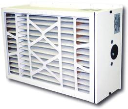


3 Module IT Introduction to Hi-Velocity (1/3) Common Parts* Vent Plate Elbow Rough-In Boot Joint Connector Flexible Duct Branch Take-Off End Cap Cooling Options RPM-E Pre-Piped Cooling Module - Pg. 29 WCM Chilled Water Module - Pg. 36 Other Options Hi-Velocity Air Purification System Heating Options Plenum Duct Connection Tee HWC Hot Water Coil - Pg. 37 ESH Electric Strip Coil - Pg. 38 Circuit Board - Pg. 21 WEG Variable Frequency Drive - Pg. 22 Module IT Introduction to Hi-Velocity (1/3) -3- Hi-Velocity Fan Coil *Example Configuration Only
4 Hi-Velocity Series Installation Manual Module IT Introduction to Hi-Velocity (2/3) Thank ou for Purchasing the Finest in Indoor Air Quality Systems. The Hi-Velocity System is an energy efficient high pressure air delivery system that can be designed to provide heating, cooling, filtration, ventilation, humidification and dehumidification. Ease of Installation The Hi-Velocity System can be installed in 25 percent less time than a traditional heating system and is equally suitable for commercial and residential, in both new construction and retrofit applications. For residential applications where every cubic foot of area is critical, the Hi-Velocity System is the solution to your heating and cooling needs. Being able to run duct work into places where standard duct work would not fit, allows heating, cooling and ventilation to be installed in applications where the options are very limited. The Hi-Velocity System works on the principle of pressure rather than air velocity. It is quite different than a conventional furnace, the main difference being that the supply duct work is all small diameter or mini duct, which takes about 75% less space than conventional ductwork. With a pressurized small diameter duct we condition the air differently than conventional forced air systems. With the use of a high pressure area to low pressure area, we continuously mix the room air, creating even temperatures from floor to ceiling. Because the plenum duct is pressurized, dust build-up within the duct work is eliminated. With continuous air circulation from the constant fan, airborne dust and other allergens can be easily filtered out of the air, and conditions that promote the growth of mold and mildew are reduced. Our innovative fan coil and unique cooling module technology helps create a healthier and more enjoyable indoor living environment for the end-user, while saving money on monthly operating costs. Powered by a variable-speed VFD motor, the Hi-Velocity System can be used for heating, cooling, or a combination of both. The VFD motor quietly drives the system s fan continuously, limiting wear and tear and increasing the lifespan of the system. We are confident that you will enjoy years of trouble-free service from your Hi-Velocity System. As with any product that requires installation and assembly, a good understanding of ALL the components and the final product is necessary to achieve the optimum result. This manual has been designed to be as concise and straightforward as possible. Please read the ETIRE manual before beginning installation as this will help avoid mistakes that may cost time and money. Primary Applications: Heating Up To provide heating, the system can be used in conjunction with DX heat pumps or any water source (hot water tank, boiler or geothermal). Unlike traditional heating and air conditioning systems, it does not depend on the natural laws of convection. A network of smaller, flexible ducts operate under high pressure to continuously circulate air and ensure even heat distribution. When using a hot water tank, after going through the heating system, the hot water is recycled for household use. With a proper tank, the Hi-Velocity System can reduce energy requirements by up to 50 percent. Cooling Down For air conditioning, a cooling module, condensing unit, chiller, heat pump or geothermal sytem can all be used. The high pressure distribution network cools each level of the structure evenly. Use of a lower CFM across the cooling coil means that the Hi-Velocity System can remove up to 30% more moisture from the air than conventional systems, leaving a constant and comfortable temperature on the skin surface. Breathing Right IAQ is integral to the comfort and health of a building s occupants. The optional Hi-Velocity Air Purification System (HE PS) was designed to complement the heating and cooling system. It contains three powerful technologies. First, an electrostatic MERV-13 filter removes allergens. Photo-catalytic oxidation is then used to destroy toxic chemicals and eliminate odours. Finally, Ultraviolet Light is used to kill germs on contact. The result is clean, purified air, and unsurpassed Indoor Air Quality for your home or office. For all of your heating, cooling, and Indoor Air Quality needs, the Hi-Velocity System is the right choice for you! Module IT Introduction to Hi-Velocity (2/3) -4-
5 Module IT Introduction to Hi-Velocity (3/3) Fan coil units shall be a total indoor air quality system complete with heating, cooling, air filtration, and possibility of humidity control and fresh air make up. The fan coil must be factory manufactured, assembled and tested. Refer to Module SPC - Specifications and Sizing for system specifications, measurements, etc. For more detailed specification pages please see our website. Also available on our website: Installation Videos Promotional Video Engineering Specifications Applications Downloadable Installation Modules Performance Graphs Brochures and Marketing Tools Complete Parts List Complete list of Agents/Distributors ews and ewsletters Case Studies Quality Assurance All equipment furnished under this specification shall comply with the following standards: ASHRAE AHRI CSA CE DOE UL American Society of Heating, Refrigerating and Air-Conditioning Engineers Air-Conditioning, Heating, and Refrigeration Institute Canadian Standards Association European Conformity Department of Energy Underwriters Laboratories IMPORTAT: The Hi-Velocity System is not to be used for temporary heating or cooling during the construction of the structure. If used in this capacity all warranties will be null and void. WARRAT Three year limited warranty. The VFD Motor, WEG Controller (HE-Z/HE-B/LV-Z Units), PSB Circuit Board (HE-Z/LV-Z Units) HEB Circuit Board (HE-B Units) and the VFD Motor, EPC Controller, EPC Circuit Board and PWM Control (HE Units) are free from defects in workmanship for three years from date of purchase. Two year limited warranty. The Electric Strip Heater is free from defects in workmanship for two years from date of purchase. One year limited warranty. The Heating Coil (Heat Exchanger), Air Conditioning Coil, Chilled Water Coil, Blower and PSC motor and electrical components (HV/LV/JH Units) are free from defects in workmanship for one year from date of purchase. This warranty applies strictly to the first purchaser and only to the fan coil unit. It does not include connections, attachments and other products or materials furnished by the installer. This warranty excludes any damages caused by changes, relocation to, or installation in a new site. This warranty does not cover any defects caused by failure to follow the installation and operating instructions furnished with the fan coil. This warranty does not cover defects caused by failing to adhere to local building codes and following good industry standards. Failure to correctly install the fan coil, or material related to the unit, may result in improper system performance and/or damages and will void this warranty. Using the fan coil as a source of temporary heating/cooling during construction, will void this warranty. Terms and Conditions Any repair performed under warranty must be approved by Energy Saving Products Ltd. for this warranty to be valid. The manufacturer is not liable for any other damages, personal injury, or any other losses of any nature. The liability of the manufacturer is limited to and shall not exceed the cost of pre-approved replacement parts and shall not include transportation to and from the factory, and field labour. Inoperative parts must be returned with serial number, purchase date, and a detailed description of the entire problem with an ESP RMA Form. This warranty replaces all other warranties expressed or implied. Disclaimer Energy Saving Products Ltd. reserves the right to discontinue, make changes to, and add improvements upon its products at any time without public notice or obligation. The descriptions and specifications contained in this manual were in effect at printing. Some illustrations may not be applicable to your unit. Module IT Introduction to Hi-Velocity (3/3) -5-
6 Module OTL Hi-Velocity Outlet Installation (1/2) BEFORE OU BEGI ISTALLATIO: A heat load calculation and duct layout is required before any installation can begin. See the Design Manual, for your unit before you begin installation. The layout is designed to provide you with the maximum benefit from your Hi-Velocity System. Small deviations may be necessary due to existing construction. However, please contact your system designer before proceeding if large deviations must be made such as: Fig. OTL-02 - Six/Seven inches (152mm/178mm) on center 6/7 (152/178mm) 6/7 (152/178mm) Elimination of a vent from a room Moving a vent more than 10 feet (3.05m) from it s specified location Re-routing the main plenum Outlet Installation With the venturi effect of the Hi-Velocity system, you have more options in vent placement. Each vent has an effective throw of 18 (5.49m) and causes the air to constantly circulate. (Fig. OTL- 01) This allows for vent placement in floors, ceilings, or walls. Constant circulation is very important to maintain room comfort. Do not install vents under/beside/on-top of objects that may hamper the cone of influence from circulating the room air. In the event of an unavoidable obstacle, the vent plate can be equipped with our optional 15 o louvered insert. PLEASE OTE: HE flex duct outlets can not be used for 2 X 4 (51mm X 102mm) sidewall applications. Locating Vents Outlets do not have to be located on an outside wall. Due to the venturi action of the Hi-Velocity System, the air in the entire room is gently circulated at all times. The outlets should be located six inches (152mm) on centre from any possible obstruction, seven inches (178mm) for HE outlets. (Fig. OTL-02). Fig. OTL-01 - Cone of Influence Proper location is critical to the operation of the Hi-Velocity System for optimum home comfort. The outlets should be located where it is considered to be a low traffic area. Typical areas are in the corner of a room, or to the side of a window or door. When the vents are properly located, the home owner can expect to have a nearly draft free home. Vent placement in outside walls of the structure should be avoided. Flexible duct that is run in outside walls may receive a substantial heat loss/gain. This can result in a higher operating cost for the structure while delivering an inferior air quality. Module OTL Hi-Velocity Outlet Installation (1/2) -6-
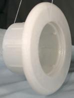
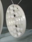
7 Module OTL Hi-Velocity Outlet Installation (2/2) Installing the Rough-In Boot Once a suitable unobstructed location has been chosen for the vent placement, use a 3 (76mm) hole saw to drill an opening large enough for the Rough-In Boot with a Rough-In Cap (Fig. OTL-03). For HE, use 3 3/4 (94mm) hole saw. Before securing the Rough-In Boot, make sure to use a Rough-In Cap (Fig. OTL-04). Rough-In Caps are used during construction to prevent damage during construction from drywall dust, saw dust, stipple ceiling, paint and other small particles from clogging and damaging the Rough-in Boot and Fan coil unit. In floor applications simply place the cap over the boot before installing the boot. In ceilings or sidewall applications it may be necessary to tape the cap on to the Rough-in boot to hold into place prior to installation. To prevent damage during construction, do not cut out the Rough-In Caps until the vent plates are ready to be installed. 4a Fig. OTL-03 - Drill a 3 or 3 3/4 (76mm/95mm) hole 4b Installing Vents in Kick Spaces In kitchens and bathrooms, it is sometimes hard to find a low traffic area, so an alternative is to locate the vents in the kick space under the counters. Our Vent plates have a 4 (102mm) or 5 (127mm) diameter, which may not fit in all kick spaces without trimming. This can easily be done by trimming the top and bottom of our vent plate so it fits. HE outlets are not recommended for kick spaces. The easiest way to install the round vent plates in the kick space is to trim off two edges of the plate. (Fig. OTL-05). 4c 4d Fig. OTL-04 - Rough-In Cap Installation Fig. OTL-05 - Trim the edges for kick spaces 4a - Rough-In Cap fits on Rough-In Boot 4b - Rough-In Boot installed with a Rough-In Cap 4c - Floor installed Rough-In Boot 4d - Wall installed Rough-In Boot By locating the vents in this position, there will now be horizontal airflow. Caution should be exercised when locating vents in the horizontal position. Avoid placing vents directly below sinks or other locations people will be for extended periods of time. Module OTL Hi-Velocity Outlet Installation (2/2) -7-
8 Module FCP Hi-Velocity Fan Coil Placement (1/2) Fan Coil Placement The Hi-Velocity System fan coil is manufactured with a direct drive permanently lubricated VFD Motor that is mounted within the blower. All Hi-Velocity fan coils are single side access. The blower assembly can easily be slid out by removing the three mounted bolts that attach it to the center plate. In some instances, the electrical box may need to be removed. Location The fan coil unit is to be placed according to the layout provided by the designer. As with vent placement, small deviations can be made in fan coil placement. If the fan coil has to be moved more than a few feet from it s pre-designed location, contact the designer before proceeding. When installing the fan coil keep these points in mind. Fig. FCP-02 - Counter flow When placed in the Counter flow position, the supply air delivery is from the bottom of the unit (Fig. FCP-02). Serviceability and access to the unit. Maximizing usable floor space. Location of heat/cool source to fan coil. The fan coil can be installed in many different configurations. The fan coil can be located in a Hi-Boy, Counter flow, or Horizontal position. In the Hi-Boy position, the supply air is delivered from the top of the unit (Fig. FCP-01). Fig. FCP-03 - Horizontal installation Quite often, the best location for the fan coil unit is suspended from the ceiling of the mechanical room, in the horizontal position (Fig. FCP-03). This will allow for more floor space in the room, and will minimize the duct work needed to connect to the fan coil unit. Clearances Clearance is only needed on the access side of the units. However, ensure that there is a small space between the unit and any other surface to prevent vibration transfer. In order to maintain and service the fan coil unit, minimum clearances are required on the access side (Table FCP-01). Fig. FCP-01 - Hi-Boy Table FCP-01 Fan coil clearances Unit Inches 50/51/52 18 (457mm) 70/71 22 (559mm) 100/ (737mm) Add an additional 4 (102mm) for Electric Strip Coils Module FCP Hi-Velocity Fan Coil Placement (1/2) -8-

 Hanging the Hi-Velocity Unit 1/4 LOCK UT (6.")
 Secure the nylon straps to the joist or support.")


.")
 Fig. FCP-05 - Attach flanges to Unit Fig.")
.")


9 Hanging Strap Kit The Hanging Strap Kits are designed to suspend a horizontal or vertical fan coil. The nylon straps will absorb most of the vibration generated by the fan coil system, eliminating any sound transfer. Alternative hanging methods may be used, e.g. Reddy Rod or Unistrut. BOLT Fig. FCP-04 - Hanging Strap Kit Components 5/16 WASHER (7.9mm) Hanging the Hi-Velocity Unit 1/4 LOCK UT (6.4mm) 5/16 X 3/4 SELF TAPPIG SCREW (12.7mm) METAL FLAGE Module FCP Hi-Velocity Fan Coil Placement (2/2) Secure the nylon straps to the joist or support. It may be necessary to install a support across the joists to properly fasten the ylon Straps (Fig. FCP-08). The ylon Straps are always installed in a vertical position; they should never be installed at an angle. It is acceptable to put a 90º twist in the ylon Straps (Fig. FCP-08a), do not exceed 90º. Fig. FCP-08 - Install Support if eeded X8 X8 X16 X8 24 LO STRAP X8 Fig. FCP-08a - 90 twist X4 Hanging Fan Coil Unit Only Attach the metal flanges to the four facing corners of the fan coil unit (Fig. FCP-05). Cut the nylon straps to the desired length (4 /102mm or more) and drill a 3/8 (7mm) hole 1 (25mm) from the end of each nylon strap. (Fig. FCP-06) Fig. FCP-05 - Attach flanges to Unit Fig. FCP-06 - Cut Hole in Straps 1 (25mm) Slide the 1 ¼ (32mm) bolt into the hole of the metal flange then into the nylon strap, secure with washer and nut. Repeat this at each end of the nylon straps (Fig. FCP-07a,07b). FCP-07a X Lift the fancoil unit and slide the bolt into the metal flange located on the unit through the nylon strap, and finish with the washer and nut. Hanging Fan Coil Unit with Cooling Coil Using the L brackets provided with the cooling coil, attach the module to the return side of fan coil unit, using two sided tape for air seal between units. Assure that drain connections are on the bottom (Fig. FCP-09), and that no screws puncture the drain pan or coil. The WCM and WM chilled water coils are a horizontal airflow with a vertical position of the coil while the RPM-E is also a vertical coil with multiple air flow capabilities. See the corresponding manual included with the coil for detailed installation instructions. Fig. FCP-09 Attach Cooling Coil to Fan Coil Unit Fig. FCP-07 - Attach Flanges to all Straps Attach the metal flanges to the four facing corners of the fan coil and cooling coil assembly. FCP-07b After attaching the metal flanges, follow the same steps for hanging fan coil unit only. Module FCP Hi-Velocity Fan Coil Placement (2/2) -9-
 in the basement (Fig. DUC-01). Fig. DUC-01 - Basement Installation www.hi-velocity.")
 Min. 18 (457mm) The main plenum can also be easily installed in the attic space. (Fig. DUC-02) Fig.")
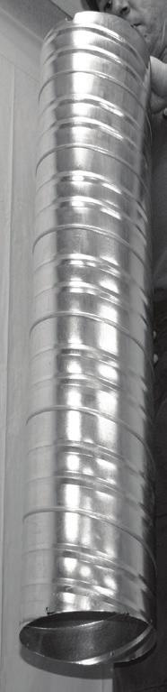
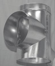
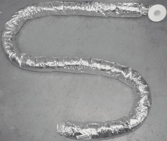
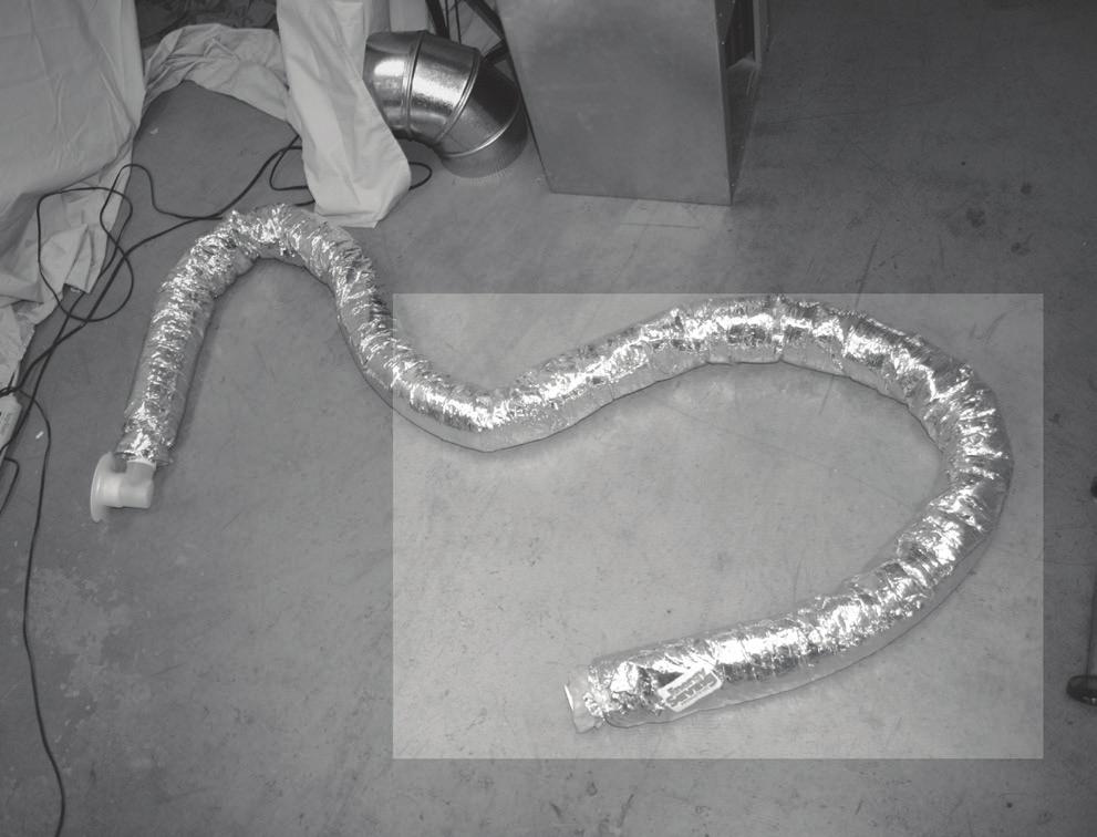
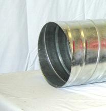
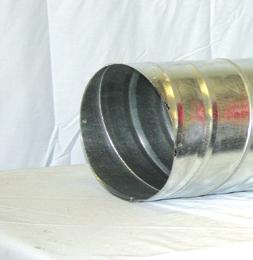
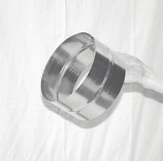
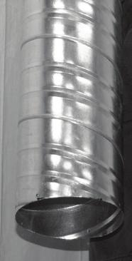
10 Plenum Duct Location When locating the plenum duct, one of the main factors to consider is the integration of the duct work into the structure. The main supply duct can be located along the main beam(s) in the basement (Fig. DUC-01). Fig. DUC-01 - Basement Installation Main Plenum Connectors There are five types of connections that are possible with the Hi-Velocity System. Fig. DUC-03 - Connectors 1. Tee Connection 2. Elbow Connection 3. Reducers 4. End Cap 5. Straight Connection Module DUC Installing Plenum and Branch Duct (1/9) Min. 18 (457mm) The main plenum can also be easily installed in the attic space. (Fig. DUC-02) Fig. DUC-02 - Attic Installation IF THE DUCT IS LOCATED I A UCODITIOED AREA, ISULATIG SLEEVE IS REQUIRED O THE MAI PLEUM. IF USED FOR COOLIG, IT IS ALSO RECOMMEDED TO ISULATE AD VAPOR BARRIER THE MAI PLEUM AD FLEX DUCT FITTIGS. ISULSLEEVES ARE AVAILABLE AS A ACCESSOR I R4.2 AD R4.8 FOR 6 (150mm), 8 (200mm) OR 10 (255mm) PLEUMS I 10 (3.05m) LEGTHS. All of the connections are done as follows. Place the joint connector, cap, tee, or elbow inside the plenum you intend to connect. Push the plenum over the fitting as tight as possible. Use four screws on each side of the connector, alternating the screw locations as indicated in Fig. DUC (457mm) Insul-Sleeve over plenum If the unit is installed in the attic, make sure that all ducts in the attic are insulated with a vapour barrier. All A/C systems main plenums need to be insulated and vapour barriered. Fig. DUC-04 - Alternating screw locations Check with local codes for required R-Value. This includes the Branch Take Off and the vent Rough-In Boot. All main plenum and flex runs should be installed under the attic insulation. If the duct work is run above the attic insulation, an extra insulation sleeve may be needed. Check your local building code for the ruling in your area. Flexible duct is OT to be used for supply air plenum. For any duct runs over 75% of the maximum allowable plenum length (Module SPC - Specifications and Sizing Pgs. 1, 2), it is recommended to insulate the main plenum. Insulating the main plenum will cut down on your duct loss, and form a vapour barrier. The attic insulation should be placed over all Hi- Velocity System ducts to further reduce any duct losses. Elbow and Tee Placement Elbows and tees must not be placed any closer than 18 from supply outlet on the air handling unit. A significant loss of airflow can result if elbows or tees are installed closer than 18 (457mm). Figs. DUC-06 and Fig. DUC-07 illustrate a proper install with at least 18 of straight plenum after the unit supply outlet. Fig. DUC-05 shows the sigma velocity profile of the first 18 (457mm) of the main plenum and why it s important to allow the system to equalize air flow. Module DUC Installing Plenum and Branch Duct (1/9) -10-
 Bullhead Tees 18 (457mm) Uniform Velocity Point 10% Loss 20% Loss 30% Loss Bullhead tees are to be maintained as close to a 50/50 split as")
11 Fig. DUC-05 - Sigma Velocity Profile Module DUC Installing Plenum and Branch Duct (2/9) Bullhead Tees 18 (457mm) Uniform Velocity Point 10% Loss 20% Loss 30% Loss Bullhead tees are to be maintained as close to a 50/50 split as possible, with a maximum 60/40 split (DUC-Fig. 07). For the best system performance, keep the number of elbows and tees to a minimum. After any connection is made, including the joints of elbows and tees, foil duct tape or a duct sealant should be used to eliminate any air leaks. Fig. DUC-08 - Seal all connections IMPORTAT! ESURE plenum runs a minimum of 18 (457mm) before any tees, elbows and take-offs. If elbows, tees, or Branch-Take Off s are placed closer than 18 (457mm) you may lose up to 30% of your airflow as illustrated in Fig. DUC-05. Branch Tees When branch tees are used, the plenum split is to be a 70/30 main/branch split (Fig. DUC-06). Fig. DUC-06 - Branch Tee, 70/30 split Joist and Trusses When running the plenum duct between joists in the basement, sheet metal strapping should be used (supplied by the installer, not the factory) to secure the plenum in place (Fig. DUC-09). Fig. DUC-09 - Use Metal Strapping Fan Coil EXAMPLE 20 VETS 70% FLOW 14 Vents 18 Min. (457mm) 30% FLOW 6 Vents Fig. DUC-07 - Bullhead Tee, 50/50 split 50% FLOW (+/- 10%) 10 Vents When located in ceiling spaces, the duct may be laid upon ceiling trusses. Run the duct work low so that it can be covered with the house insulation (Fig. DUC-02). Insulation Sleeve Fan Coil 18 Min. (457mm) 50% FLOW (+/- 10%) 10 Vents EXAMPLE 20 VETS Module DUC Installing Plenum and Branch Duct (2/9) -11- Any time the duct will be run in an unconditioned space (attic or crawl space), or used in A/C mode, it must be insulated with a vapour barrier. It s also recommended to vapour barrier runs that exceed 75% of the total allowable distance (Module SPC - Specifications and Sizing Pgs. 1, 2).
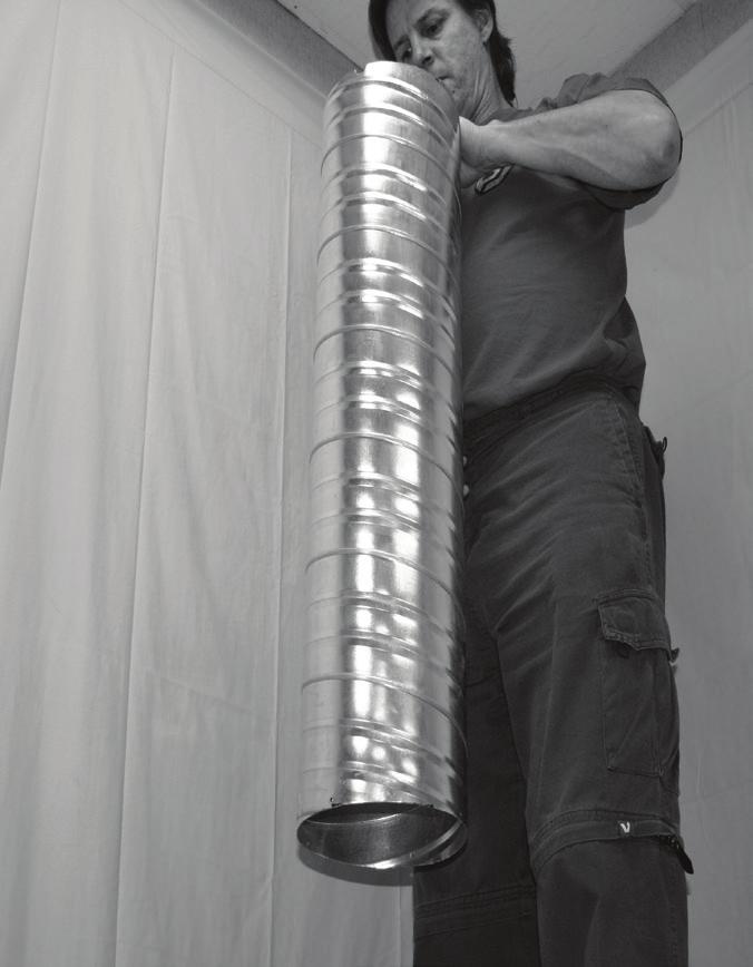
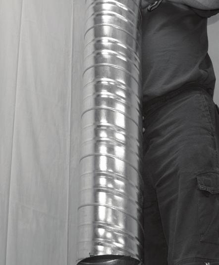
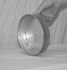
12 To install the insulation sleeve over the main plenum, either tape the end of the duct or use an end cap. This will allow the sleeve to slide on easier, and prevent the insulation from catching on the sharp metal ends of the duct (Fig. DUC-10). Fig. DUC-10 - Use an End Cap or Reducer Module DUC Installing Plenum and Branch Duct (3/9) Connecting Plenum to Fan Coil After the main plenum duct and the fan coil unit are in place, they can be fitted together. Do not permanently fasten the two together yet, as the plenum may need to be rotated in order to make the branch take-off connections. Once rotated into position, fasten and seal with duct sealant or foil duct tape. Branch Take-Off with Insulation Sleeve After the insulation sleeve is installed, cut an X through the vapour barrier and insulation. Peel it back enough to allow you to drill your hole without ripping all of the insulation. Install the branch take-off as described in the Branch Take-Off section. Tape around branch take-off to reseal vapour barrier and insulation. Fig. DUC-11 - BTO with insulation sleeve Duct Reductions (Table DUC-01) In some installations, it is necessary to reduce the size of the main plenum. Caution must be used when reducing plenum size, since smaller ducts can handle less number of outlets. Also, when running the plenum duct past 75% of max distance, it is best to keep full size plenum duct to reduce restriction in the main plenum. Keep in mind that once reduced, the main plenum cannot be increased again. The Branch Take-Offs form easily to ducts in the 6 (152mm) to 8 (203mm) range; extra care must be taken with smaller sized ducts to ensure a proper air seal. For tee reductions, keep the tee to the full duct size, if reducing the plenum duct, reduce only after the tee. Keep the length of the smaller duct sizes to a minimum, since the friction loss is much higher. If a hole saw will be used to drill the Branch Take-Off holes, metal ducts are recommended to be 28 gauge steel. Duct Size Table DUC-01 - Duct Reductions # of HE Vents # of 2 (51mm) Vents Max Length 4 (102mm) /A 4 30 (9.14m) 5 (127mm) (12.19m) 6 (152mm) (15.24m) 7 (178mm) (18.29m) 8 (203mm) (21.33m) 10 (254mm) (30.48m) Module DUC Installing Plenum and Branch Duct (3/9) -12-
13 Flexible Branch Duct With both the Main Plenum and Rough-In Boot installed, there is now only the connection of the two. This is done with the 2 (51mm) or HE Flexible Branch Duct. Keep in mind that the minimum duct length is 10 feet, with a maximum length of 25 feet (7.62m). Branch duct runs should be kept as short as possible to maximize the airflow through these runs. Energy Saving Products supplies the 2 (51mm) and the HE flexible duct in three different configurations: 2 (51mm) x 10 (3.05m) AFD (Assembled Flex Duct) 2 (51mm) x 15 (4.57m) AFD (Assembled Flex Duct) 2 (51mm) x 25 (7.62m) UFD (Unassembled Flex Duct) HE x 10 (3.05m) AFD (Assembled Flex Duct) HE x 15 (4.57m) AFD (Assembled Flex Duct) HE x 25 (7.62m) UFD (Unassembled Flex Duct) All configurations are available in both R4.2 and R8 R Values. The 2 (51mm) and HE AFD come complete with the necessary components for one complete ten foot or fifteen foot branch run. The 25 (7.62m) UFD is to be used only to extend these runs if needed. If extending branch runs longer than the minimum 10 length, contact the system designer, or reference Table DUC-02 for branch duct losses on extended runs. Outside Diameters of Flexible Duct: 2 - R4 = 4.5 (114mm) 2 - R8 = 6.5 (165mm) HE - R4 = 5.5 (140mm) HE - R8 = 7.5 (191mm) Table DUC-02 - De-rating Values Tubing Length Adjustment Factor 2 and HE Flex Duct 10 0% HE Duct 15 10% 20 20% HE Duct is designed as a direct alternative for two 2 (51mm) flex duct of the same length used in Hi-Velocity Systems. o changes are required to fancoil selection and main plenum duct sizing % Duct Size Flexible Duct Example: If a 3 Ton Unit has 24 outlets of the normal 2 X 10 (51mm) flex duct, you can change to 12 HE X 10 Duct outlets, or 8 HE Duct and 8 2 (51mm) Duct outlets, or any combination to give you the equivalent. See Specification & Sizing Pgs 1,2 for Air Flow data. Branch Take-Offs (BTO) Max CFM Output TWO 2 (51mm) Flex Duct 32 CFM X 2 (15 L/s X 2) OE HE Duct 65 CFM (31 L/s) The locations for the Branch Take-Offs should be determined before any drilling is done. Holes need to be drilled a minimum of 6 apart on center (152mm) for 2 flex, and 7 (178mm) apart on center for HE flex. Once all spots are marked for the Branch Take-Offs, a hole saw is used to drill the outlets - 2 1/2 (63mm) for 2 (51mm) Branch Take-Offs and 3 ¼ (82mm) for HE Branch Take-Offs. (Fig. DUC-12). Fig. DUC-12 - Drill Hole It is OT recommended to connect any Branch Take-Offs until all holes have been drilled, as it may be necessary to rotate the plenum to drill the outlets. After all the holes have been drilled in the main plenum, the Branch Take-Offs are then installed. The Branch Take- Off is placed over the hole with the gasket in between (Fig. DUC-13a). The curvature of Branch Take-Off is aligned so it matches the shape of the plenum. With the opening fully over the hole push the BTO tight against the main plenum and secure with four ¼ (7mm) self tapping screws (Fig. DUC-13b). Fig. DUC-13a - Branch Take-Off Module DUC Installing Plenum and Branch Duct (4/9) HE Duct utilizes the same selecting process as the standard 2 (51mm) flex duct, a complete and comprehensive heat loss/gain must be completed in order to select fancoil, plenum size, and outlet quantities. The HE Duct is designed to directly replace two (2) standard 2 (51mm) outlets, therefore when an area requires multiple outlets, a single HE outlet can replace two of the standard 2 (51mm) ducts. Any combination of 2 (51mm) ducting, HE ducting, and drilled outlets can be used, following the minimum and maximum outlets as per unit selection. Fig. DUC-13b - Securing Module DUC Installing Plenum and Branch Duct (4/9) -13-
14 Flexible Duct Placement After all of the Branch Take-Offs have been installed, the flexible duct can then be fastened to the joist with strapping material. Staples may be used, as long as the insulation sleeve isn t damaged or torn. Only use staples if local code allows. If the insulation sleeve is damaged use foil duct tape to seal the sleeve, do not use cloth style tapes as they will not create a proper seal. Try to run the flexible duct parallel to the joists whenever possible as this takes less space (Fig. DUC-14). Module DUC Installing Plenum and Branch Duct (5/9) When larger holes (4 /102mm) can be drilled, then the insulated flex duct may be pulled through whole. If code or the designer only allow for a 2 3/8 (60mm) or 3 (76mm) hole, the insulation must first be removed from the flexible duct (Fig. DUC- 16a). The insulation is then cut into lengths that correspond to the joist spacing. As the inner soft core of the flexible duct is fed into each hole the insulation is slid over the core (Fig. DUC-16b). Fig. DUC-16a - 2 3/8 holes (60mm) Fig. DUC-14 - Use strapping to hold the Flexible duct Fig. DUC-16b - Add insulation at each joist When installing the flexible duct in areas in which you must run opposite to the direction of solid joists, some drilling may be required. It is recommended to drill the smallest hole possible (Fig. DUC-15) in order to maintain structural integrity. Check with local code laws and ensure that it is allowable to drill holes through the joists before proceeding. If possible, run the flex duct under the joists and avoid drilling any holes. Fig. DUC-15 - Through or under joists If a T-Bar ceiling is going to be installed, it is far easier to run the flexible duct in that space, rather than drilling through several joists. The flexible duct should never be cut shorter than 10 (3.05m) in length. If the run to the outlet is less than 10 (3.05m) the flexible duct can be coiled up. The bends in the flexible duct shall have a minimum radius of 6 or 152mm (7 or 178mm for HE Duct) (Fig. DUC-17). Sharp bends in the flexible duct will reduce airflow to that vent. Also note that runs that are perfectly straight, or stretched out too far, can also have a higher noise volume than usual. Fig. DUC-17-6 (152mm) minimum radius on bends MI. 6 or 152mm BED RADIUS (7 or 178mm for HE) Module DUC Installing Plenum and Branch Duct (5/9) -14-
15 Connecting to the Main Plenum The Flexible Duct coupling is connected to the branch Take- Off, then mechanically fastened with at least one ¼ (6.7mm) self tapping screw. The connection then should be sealed with foil duct tape or an approved sealant. Fig. DUC-18 - Secure to plenum with gentle bends Module DUC Installing Plenum and Branch Duct (6/9) Fig. DUC-20 - Fasten with tie straps SLIGHT AGLE Hard angles should never be used when connecting to the main plenum or Rough-In Boot, keep the bends as gentle as possible (Fig. DUC-18). A hard bend should never be created in the flexible duct as this will restrict airflow to the outlet. Connecting to Rough-In Boot SLIGHT AGLE The Flexible Duct coupling is connected to the Rough-In Boot, then mechanically fastened with at least one ¼ (6.7mm) self tapping screw (Fig. DUC-19). The connection then should be sealed with foil duct tape or an approved sealant. The Rough-in Boot can be insulated and vapor barriered using the insulation and vapor barrier that is around the flex duct. Cut the cable tie on the flex duct and pull insulation and vapour barrier over the flange of the Rough-In boot. Secure insulation and vapour barrier in place using a cable tie, tape or other means of securing the insulation and vapour barrier. Ensure that damperable boot will still turn. Fig. DUC-19 - Mechanically Fasten Extending the AFD with a UFD kit When connecting the UFD to the AFD, attach the branch coupling into the inner core of the UFD with foil duct tape, connect the two branch couplings with the branch connector tube (Fig. DUC-20). ow pull the insulation and vapour barrier over the inner core and secure around the outside of the vapour barrier with a cable tie. Tighten the cable tie securely around the branch connector, inner core, insulation, and vapour barrier. Module DUC Installing Plenum and Branch Duct (6/9) -15- Unconditioned Spaces If the flexible duct is in an unconditioned space, then all connections must be taped to ensure a continuous vapour seal. This includes the Branch Take-Off and the vent Rough-In Boot. Try not to damage the vapour barrier on the flexible duct. If it is damaged, holes must be taped. If possible, try to run the flexible duct between the insulation and the vapour barrier. Two Inch Metal Duct Flexible duct is not to be used in concrete applications. Caution should be used when running metal or PVC pipe under concrete, to ensure pipe is not crushed. For certain applications in which hard pipe is needed, certain guidelines must be followed. All metal ducts run in a concrete slab must be sealed with an approved duct sealer. For vertical runs out of the floor, it may be necessary to extend the damper tube or vent plate collar (Fig. DUC-23), to connect to the AFD Kit. Flexible Duct Termination To complete the installation, cut out the Rough-In Cap (Fig. DUC-21) and install the vent plate by sliding the vent plate into the end of the damper tube (Fig. DUC-22). Ensure the vent is in the fully open position. Fig. DUC-21 Fig. DUC-22 Vent Plate Extensions When the sub floor and floor finishing is too thick for the connection of the vent plate, it may be necessary to use a Vent Extender kit (branch connector tube, vent plate collar). Connect the vent plate to the connector tube, the other end of the connector tube to the collar, and attach the collar to the installed rough-in boot (Fig. DUC-23). The branch connector tube can be cut to different lengths so the vent plate sits flush with the floor finishing. Fig. DUC-23 - Extension kit OTE: TEST SSTEM FOR LEAKS BEFORE ISTALLATIO OF DRWALL.
 hole saw, drill a hole where the vent outlet is to be placed (Fig. DUC-24).")
16 Installing 2 Vents in Retrofits For ease of installation, it is recommended to use the 2 (51mm) flexible duct and vents for retrofit applications. With the proper preparations, installing vents into finished walls and ceilings is quick and simple. Using a 3 (76mm) hole saw, drill a hole where the vent outlet is to be placed (Fig. DUC-24). The hole needs to be enlarged in the direction of the incoming flexible duct. This is done by creating a (57mm) x 1 2 (13mm) rectangle, which will allow the Rough- In Boot to slide easily into the wall. Fig. DUC-24 - Dimensions 3 (76mm) 3 1/2 (89mm) Module DUC Installing Plenum and Branch Duct (7/9) Fig. DUC-27 - Secure flex to Rough-In Boot ext the flex is fed back into the wall and Rough-In Boot slid into the hole (Fig. DUC-28). Fig. DUC-28 - Feed the flex back into the wall Fig. DUC-29 - The Top (57mm) Once the hole is finished, run the flexible duct through the wall/ceiling to the vent outlet. If installed in drywall, care must be taken when pulling the flex out of the opening (Fig. DUC-25). Too much force can result in damage to the dry wall. Fig. DUC-25 - Run flex through opening The Rough-In Boot is placed at the top of the hole; top is the opposite side of the cut out rectangle (Fig. DUC-41). If being installed in drywall, with the boot seated firmly against the top, 3 pilot holes need to be drilled for 1/4 (6.7mm) drywall anchors (Fig. DUC-30). In drywall applications, 3 drywall anchors (1/4 or 6.7mm) should be used to secure the Rough-In Boot to the wall (Fig. DUC-31). Fig. DUC-30 - Pre-drill for anchors Fig. DUC-31 - Anchors The Rough-In Boot needs a little preparation before it can be mounted to the flexible duct. The corners need to be trimmed along the score lines of each corner (Fig. DUC-26). This will allow the Rough-In Boot to be completely hidden with a beauty ring (Fig. DUC-32). Fig. DUC-26 - Trim off the 4 corners Once drywall anchors are installed, screw down the Rough-In Boot and secure it in place. The vent plate can now be attached to the Rough-In Boot. Be sure vents are turned all the way counter-clockwise, to the fully open position. The Rough-In Boot is then connected to flexible duct and mechanically attached with a self tapping screw (Fig. DUC-27). Module DUC Installing Plenum and Branch Duct (7/9) -16-
.")
 vents must be a minimum of 6 (152.4mm) on center from each other, 7 (178mm) for HE vents. (Fig. DUC-35).")
17 Module DUC Installing Plenum and Branch Duct (8/9) Linear Grills Installations in areas that have a high heat loss/gain require multiple vents. Multiple vents can be installed into linear grills for a more esthetically pleasing look. Installing in a high sidewall/ ceiling or floor makes little difference (Fig. DUC-33). A Straight Vane vent grill is the only type of linear grill that can be used with the Hi-Velocity System (Fig. DUC-34). Linear grills must be purchased from a third party vendor. When installing multiple vents into linear grills, the 2 (51mm) vents must be a minimum of 6 (152.4mm) on center from each other, 7 (178mm) for HE vents. (Fig. DUC-35). Same rules apply for vents in linear grills as a single outlet installation; see Module OTL - Outlet Installation for more information on vent placement. Fig. DUC-35-6 /7 Apart on Center (152mm/178mm) 6 /7 (152mm/177mm) 6 /7 (152mm/177mm) Fig. DUC-33 - Linear Grills The outlet of the Rough-In Boot must be no more than 2 (51mm) away from the grill (Fig. DUC-36). Fig. DUC-34 - Straight vanes only Fig. DUC-36 - Outlet no more than 2 (51mm) from grill 6 /7 (152mm/177mm) 2 (51mm) Installing the vents around the room will allow for the room air to mix. This will give the room a more even air temperature and better distribution. Module DUC Installing Plenum and Branch Duct (8/9) -17-
 Plenum Runs on Ceiling Caution must to be used when not using the flexible duct, the air velocity from the drilled outlet may create noise.")

18 Drilled Outlets Module DUC Installing Plenum and Branch Duct (9/9) Plenum Runs on Ceiling Caution must to be used when not using the flexible duct, the air velocity from the drilled outlet may create noise. Drilled Outlets CAOT be installed in a residential structure; too much noise may be generated from the outlets. In commercial areas with large ceilings the sound can be absorbed by the room or is not a concern because of the ambient noises. Drilled outlets are commonly used to supply a large area with heating and cooling. Drilled outlets can also be used to create a pressurized air curtain for bay doors, or large openings to the outside environment. When drilled outlets are used with the Hi-Velocity System a few points to remember: When drilled outlets are used in a ceiling install, drill the outlets at a 45 angle to properly circulate the room air (Fig. DUC-38). Fig. DUC-38 - Airflow 45 angle to floor When multiple (32mm) or 2 (51mm) holes are used, they need to be a minimum of 6 (152mm) apart on center (Fig. 37). One (32mm) drilled hole is equivalent to a single 2 x10 AFD kit (2 /51mm Rough-In Boot attached to a 10 /3.05m piece of flex duct). With the (32mm) drilled outlet the throw from the outlet is up to 18 (5.49m). One 2 (51mm) drilled outlet is equivalent to two - 2 x10 AFD kits (2 /51mm Rough-In Boot attached to a 10 /3.05m piece of flex duct). With the 2 (51mm) drilled outlet the throw from the outlet is up to 30 (9.14m) in distance. Plenum Runs on Sidewall For sidewall installations the outlets are drilled parallel to the floor (Horizontal airflow). When the vents are in this configuration, they can be used to create a pressurized air curtain. Fig. DUC-39-6 (152mm) Airflow parallel to floor Using drilled outlets larger than 2 (51mm) is not recommended; with too large of an opening in the main plenum the static pressure may drop to an unacceptable level. Fig. DUC-37-6 (152mm) Apart on center If there is an air velocity noise coming from the drilled outlets, a static pressure reading from the plenum duct should be taken. This reading is to be taken no closer than 18 (457mm) from supply air outlet of fan coil. Static pressure readings are taken from the inside edge of the plenum; do not insert pitot tube deeper than 1 4 (6.7mm) from the inside surface of the plenum. If the static pressure is high, drilling more holes into the main plenum will lower the static pressure and the noise level of the system. The standard supply pressures for the Hi-Velocity System runs between 0.7 H 2 O (174 pa) and 1.2 H 2 O (299 pa). Do not allow the static pressure to drop below 0.7 H 2 O (174 pa) as this can cause a low airflow. Module DUC Installing Plenum and Branch Duct (9/9) -18-

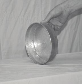
19 Return Air Module RAI Return Air Installation (1/2) When designing the return air for a Hi-Velocity System, there are a few things to consider. It is common to use centralized return air with systems that have rooms that are within a common area. Separate floors or rooms that have high loads and require a large amount of supply air flow should have their own return air, or be tied into the centralized return air to allow the air to return back to the fan coil. Rooms or areas that cannot be tied into the return air should have an air transfer grill to allow the air to escape the room and flow back to a centralized return air. The Hi-Velocity System is a pressure supply duct system that forces the air into rooms through supply outlets. A closed room will pressurize, and air will escape through the undercut of a door back to a centralized return air. (i.e. a typical bedroom with two 2 outlets or 1 HE outlet will deliver 64 cfm into the space, a 1/2 undercut door will provide 15 square inches of r/a from the space at a transfer velocity of 4 fpm, sufficient to provide comfortable r/a.) If more than four 2 or two HE vents are installed in a room, or if there is a sealed door in the room, an air transfer grill or return air should be installed to allow the air back to the fan coil. The return air duct is not supplied with the Hi-Velocity System. It is to be supplied and installed by the contractor. The return air and fresh air make-up ducts are to be installed according to local building code. The return air duct from the air handling units is to be acoustically lined for sound absorption, for the first five feet, or for the line of sight. This only applies on short return air duct work of less than 10 feet (3.05m). Duct Sizing The return air is to be sized on a 0.15 static pressure (37 pa) as compared to 0.10 static pressure (25 pa) for conventional forced air systems. The maximum length for an individual return air duct is fifty feet (15.24m). Table RA-01 has recommended return air sizes for round and rectangular ducts. A variance of plus 20% is allowable for sizing return ducts that connect to the Hi-Velocity Systems unit. Table RA-01 Return Air Duct Sizes Unit Rigid Ø Flex Ø 50/51/52 70/71 100/ (305mm) 12 (305mm) 14 (356mm) 14 (356mm) 14 (356mm) 16 (406mm) Min Sq. Inches (Sq. cm) 120 (774cm) 120 (774cm) 168 (1084cm) Remember: When using flexible duct for return air, use one duct size larger due to the higher friction loss. Where allowed by local codes, a single return air grill may be used. ote: Return air grill must have equal minimum of free air area to return air. Important: When using flexible duct for return air, use one duct size larger due to the higher friction loss. Return Air Cutout Once the placement of the return has been decided, the return air knockout(s) can be cut. (Fig. RA-01) The pre-measured guide cuts supplied with the fan coil should always be used; this will guarantee maximum airflow across the coil. Fig. RA-01 - Return air cutout Please note: It is VER important OT to undersize the return air, as this will create noise, increase motor power consumption and reduce airflow. Table RA-02 Return Air Cutout Dimensions Model Dimensions 50/51 H/BU 9 1/2 X 13 1/2 (241mm X 343mm) 70/71 H/BU 14 X 13 1/2 (356mm X 343mm) 100/101 H/BU 20 X 14 (508mm X 356mm) Module RAI Return Air Installation (1/2) -19-
 18 1 2 (470mm) 14 1 2 (368mm) 21 1 2 (552mm) 1 (25.")
 A round or square return air duct can be used; they must be sized for the Hi-Velocity Systems according to Table RA-01.")
20 Module RAI Return Air Installation (2/2) Once the return air has been cut out, a transition will be needed to attach the return air duct to the fan coil (Fig. RA-03). Table RA-03 Return Air Base dimensions A B C D E Fig. RA-02 Return Air using a transition RA (572mm) (470mm) (368mm) (552mm) 1 (25.4mm) RA (572mm) (470mm) (495mm) (552mm) 1 (25.4mm) RA (572mm) (470mm) (648mm) (552mm) 1 (25.4mm) A round or square return air duct can be used; they must be sized for the Hi-Velocity Systems according to Table RA-01. Before the return air can be attached to the transition, the first five feet (from the fan coil) is to be acoustically lined for sound absorption. Return Air Base Energy Saving Products manufactures a return air base that matches up to the fan coil units. The return air base provides a stand for the fan coil when it will be placed in vertical orientation. Allow for easy mounting location for modular coils and filter racks. It can also be used as a transition and mixing box for the return air. All return air bases come acoustically lined with half-inch sound absorbing insulation. For filter options and other Add-Ons available from Energy Saving Products, see Module OPT - Options and Add-Ons. For installation of Heating and Cooling Add-Ons, Refer to: Module RPM - Refrigerant Module Installation pgs 1-35 Module WCM - Chilled Water Coil Installation pg 36 Module HWC - Hot Water Coil Installation pg 37 Module ESH - Electric Strip Coil Installation pgs These manuals are included with the coils, and are also available online at Mounting Additional Components When mounting additional components onto the back of the unit, (Filter Rack, Return Air Base etc.) the hex head (a) screws (4 or 6 depending on unit size) can be replaced with flat head (b) screws for a flush fit. E A D C B Fig. RA-03 Hi-Velocity Return Air Base Module RAI Return Air Installation (2/2) -20-

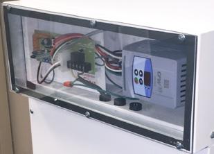
21 Module WIR Hi-Velocity Wiring & Settings (1/10) Hi-Velocity Systems HE-Z PSB Circuit Board The Hi-Velocity HE-Z Series Fan Coil utilizes a dual function Circuit Board. This circuit board makes zoning simple and easy, eliminating the need for by-pass dampers and dump zones. It also makes adjustment to airflow quick with the use of trim pots for direct control. Auxiliary Relay Terminals (Heating) VDC Control Method Switch Fan Delay 0-10v On/Off Switch DC Output Operation Mode Indicator Fan Adjustment Trimpots Pressure Sensor Indicator Light T Stat Connections Features: Emergency Disconnect Wiring the circuit board is a quick and simple task. Clearly labeled connections. o additional relays typically required. 24v Auto-Reset Fuse When the PSB is set to Auto, it allows for automatic airflow adjustments, according to the static pressure of the supply air, making zoning a breeze. Manual mode allows for direct speed control of the fan anywhere from 0-100% capability. Fan speeds in both functions are individually set for cooling, heating and constant fan using the three trim pots located on the PSB. Circuit board is capable of controlling boilers, dual purpose hot water heaters, heat pumps, and geothermal systems, as well as our manufactured slide-in electric strip heaters (ESH). The circuit board is also designed to send control signals to cooling sources such as condensing units, chillers, heat pumps and geothermal systems. Circuit board features an auxiliary relay with dry contacts connections, so that any applications requiring 24v, 120v, 230v or dry contacts (boilers, hot water heaters, heat pumps & humidifiers) can be automatically started when there s a call for heat. Circulator timer chip is provided to prevent water stagnation in potable water systems and to provide pump rotor protection for water source heating and cooling. Pump Timer on/off Switch Condenser/Zone Valve Connections If you wish to have the timer cycle operate at a specific time of day, simple turn off power to the fan coil unit for ten seconds at that time and then turn the power back on. If you do not need to use the timer, move the jumper header from the On pins to the Off pins and it will be disabled. Circuit board is equipped with an emergency disconnect feature. If there s an emergency this feature will de-energizing all fan speeds and connected equipment. For this emergency disconnect feature to be active a jumper header must be remove from the pins located close to the emergency disconnect terminal strip. A fan delay is programmed into the circuit board. This delay will prevent the fan from starting for 20 seconds on cooling, 30 seconds on heating, and purge for 30 seconds on shut-down. This delay is beneficial in certain applications to give the heating or cooling equipment a head start before the fan turns on. Function: Manages input power and through the use of a transformer it supply 24vac to additional equipment. Organizes all thermostat inputs and prioritizes them accordingly. Sends a 0-10vdc output to the VFD, dependent on how fast it wants the fan to run. Module WIR Hi-Velocity Wiring and Settings (1/10) -21-

 Error code read out allows for easy drive analysis in the event of a VFD fault Programmable drive parameters allow for acceleration and deceleration speed to be adjusted if")
22 Module WIR Hi-Velocity Wiring & Settings (2/10) WEG Variable Frequency Drive The Hi-Velocity HE-Z Series Fan Coil utilizes a WEG Variable Frequency Drive to run its 3-phase motor. The WEG VFD is a reliable and robust motor control that will provide many years of issue free operation. Features: Purposely oversized to ensure increased reliability and higher efficiencies at peak load Features inherent with VFD allows for minimum power consumption at reduced loads (<100w average for constant fan speed) Error code read out allows for easy drive analysis in the event of a VFD fault Programmable drive parameters allow for acceleration and deceleration speed to be adjusted if necessary Digital display makes motor speed references simple Large heat sink allows for excellent heat dissipation in high ambient environments Function: Takes single phase input (110v or v) and converts it to 3 phase output for the fan motor Fan speed is determined by the PSB circuit board which provides a 0-10vdc output to control the VFD Read-Only Parameters: Parameter Function Range Unit Description P002 Motor Frequency Output 0 to 66 Hz Indicates the VFD Output Frequency in Hertz P003 Motor Current Output 0 to 1.5 x I nom A Indicates the VFD Output Current in Amperes P004 DC Link Voltage 0 to 524 V Indicates the VFD DC Link Voltage in Volts P007 Motor Voltage Output 0 to 240 V Indicates the VFD Output Voltage in Volts P008 Heatsink Temperature 25 to 110 ºC Indicates the Heat Sink Temp in Celsius. The VFD Overtemp Protection (E04) acts when Heatsink Temperature reaches 103 ºC P014 Last Fault 00 to 41 EXX Indicates the Code of the last occurred Fault P015 Second Fault Occurred 00 to 41 EXX Indicates the Code of the 2nd last occurred Fault P016 Third Fault Occurred 00 to 41 EXX Indicates the Code of the 3rd last occurred Fault Fault Messages: Display Description E00 Output Overcurrent/Short-Circuit E01 DC Link Overvoltage E02 DC Link Undervoltage E04 Inverter Overtemperature E05 Output Overload (I x t function) E06 External Fault E08 CPU Error (watchdog) E09 Program Memory Error (checksum) E24 Programming Error E31 Keypad (HMI) Communication Fault 97 E41 Self-Diagnosis Error 97 Other Messages: Display rdy Sub dcb EPP Description Inverter is ready to be enabled Power supply voltage is too low for the inverter operation (undervoltage) Inverter in DC braking mode Inverter is loading factory setting Module WIR Hi-Velocity Wiring and Settings (2/10) -22-
 0-10 VDC Black Wire (-) 24v / 20va TRASFORMER 110-127 VAC L/L1 /L2 U V W PE LED L2 + - FA HEAT COOL White Orange Red Black LED L1 J8 J4 Red Black W1 W2 C G R 2")
23 Module WIR Hi-Velocity Wiring & Settings 3/10) HE-Z Fan Coil - PSB Wiring Diagram - ATMOSPHERIC PRESSURE + DUCT PRESSURE TRIM POTS (COOLIG, HEATIG, AD COSTAT FA) VFD VAC v POWER CABLE Red Wire (+) 0-10 VDC Black Wire (-) 24v / 20va TRASFORMER VAC L/L1 /L2 U V W PE LED L2 + - FA HEAT COOL White Orange Red Black LED L1 J8 J4 Red Black W1 W2 C G R 2 1 D O/B OFF DELA H4 O J2 A1 A2 A3 L F R6 H R7 C R8 G THERMOSTAT MA P I 0 MODE H3 AUTO OFF AUXILIAR RELA (HEATIG) U2 TIMER H2 O L2 L2 L1 L1 Parameter Value FZ FZ W1 W2 2 1 C R F Pcbw-001sep-042 PSB CIRCUIT BOARD Ri Ro C C J9 H1 J1 WEG COTROLLER J5 J7 J3 G BK WH R 24v OUTPUT EMERGEC DISCOECT Equipment Ground /1/50-60 MOTOR LEADS PLUG (3 PHASE) LIE I L1 L2 BK WH L2 CAUTIO FOR SIGLE STAGE COOLIG OPERATIO USE 2 OTHERWISE THE FREEZESTAT WILL BE BPASSED Ground G POWER IPUT: /1/ ATMOSPHERIC PRESSURE + DUCT PRESSURE TRIM POTS (COOLIG, HEATIG, AD COSTAT FA) VFD VAC v POWER CABLE Red Wire (+) 0-10 VDC Black Wire (-) 24v / 20va TRASFORMER VAC L/L1 /L2 U V W PE LED L2 + - FA HEAT White Black Orange Red COOL LED L1 J8 J4 Red Black W1 W2 C G R 2 1 D O/B OFF DELA H4 O J2 A1 A2 A3 L F R6 H R7 C R8 G THERMOSTAT MA P I 0 MODE H3 AUTO OFF AUXILIAR RELA (HEATIG) U2 TIMER H2 O L2 L2 L1 L1 Parameter Value FZ FZ W1 W2 2 1 C R F Pcbw-001sep-042 PSB CIRCUIT BOARD Ri Ro C C J9 H1 J1 WEG COTROLLER J5 J7 J3 G BK WH R 24v OUTPUT EMERGEC DISCOECT Equipment Ground /1/50-60 MOTOR LEADS PLUG (3 PHASE) LIE I L1 BK WH Ground G POWER IPUT: /1/50-60 EMERGEC DISCOECT C - 24 VAC COMMO C - 24 VAC COMMO Ro - 24 VAC OUTPUT Ri - 24 VAC IPUT THERMOSTAT COECTIOS R - 24 VAC OUTPUT W1 - FIRST STAGE HEAT W2 - SECOD STAGE HEAT (OR SIGLE STAGE) 1 - FIRST STAGE COOLIG 2 - SECOD STAGE COOLIG (OR SIGLE STAGE) C - 24 VAC COMMO G - THERMOSTAT FA SWITCH D - PRIORIT (RUS AT W SPEED) O/B - HEATPUMP REVERSIG 24 VAC OUTPUT COECTIOS FZ - FREEZE STAT FZ - FREEZE STAT W1 - HEATIG (W1) 24 VAC OUTPUT W2 - HEATIG (W2) 24 VAC OUTPUT 2 - CODESIG UIT 24 VAC OUTPUT 1 - CODESIG UIT 24 VAC OUTPUT C - 24 VAC COMMO R - 24 VAC OUTPUT LED LIGHT IDICATORS LED 1 - GREE LIGHT, PUMP TIMER OPERATIO MODE IDICATOR LED 2 - BLUE LIGHT, PRESSURE SESOR - EUTRAL L - LIE VOLTAGE A1 - AUXILIAR ORMALL OPE A2 - AUXILIAR ORMALL CLOSED A3 - AUXILIAR COMMO AUXILIAR HEATIG RELA JUMPER PI SETTIGS H1 EMERGEC DISCOECT: REMOVE PI IF WIRED TO EMERGEC DISCOECT H2 TIMER: AUXILIAR RELA TIMER (SEE OTES) H3 MODE: AUTO - FA SPEED MODULATES DEPEDIG UPO STATIC PRESSURE MAUAL - FA SPEED OPERATES AT TRIM POTS SET AIR FLOW H4 DELA: /20 AD W/30 SECOD FA DELA. AD W 30 SECOD POST PURGE. HE-Z/LV-Z 110V/220V REFER TO COMPLETE COMMISSIOIG REPORT PRIOR TO ORMAL OPERATIO. REPORT IS AVAILABLE WITH THE ISTALLATIO MAUAL OR OLIE AT ICREASE AIR FLOW (CLOCKWISE) DECREASE AIR FLOW (COUTER CLOCKWISE) FA ADJUSTMET TRIM POTS ADJUSTIG TRIM POTS: O POWER START UP, ALLOW 45 SECODS FOR SSTEM TO PRESSURIZE BEFORE MAKIG A CHAGES. DO OT ADJUST MORE THA A ½ TUR AT A TIME, ALLOW 30 SECODS BETWEE ADJUSTMETS FOR THE PSB TO REACH SET POIT. LED 2: PRESSURE SESIG IDICATOR (BLUE LIGHT) H3 JUMPER PI: AUTO OR MAUAL MODE AUTO MODE: LED 2 WILL SPORADICALL FLICKER (O/OFF) TO SHOW THAT IT IS PROPERL SESIG PRESSURE I THE SSTEM. * O LIGHT IDICATES TRIM POT IS ABOVE ORMAL OPERATIG RAGE (COUTER CLOCKWISE DECREASE). * SOLID LIGHT IDICATES TRIM POT IS BELOW ORMAL OPERATIG RAGE (CLOCKWISE, ICREASE). MAUAL MODE: LED 2 WILL BE OFF, ADJUST EACH OF THE AIR FLOWS TO DESIRED CFM/LPS OUTPUT. 2 SECODS 2 SECODS 2 SECODS OFF: D O: (IACTIVE) O LIGHT W O: (ACTIVE) G PUMP TIMER STATUS FA OPERATIO MODE LED 1: (GREE LIGHT) PUMP TIMER/OPERATIO MODE IDICATOR LIGHT SEQUECE 8) FAILURE TO SET PROPER AIR FLOW AD/OR OPERATIO OF THE SSTEM MA RESULT I DAMAGE TO EQUIPMET. 9) FAILURE TO READ AD FOLLOW ALL ISTRUCTIOS CAREFULL BEFORE ISTALLATIO COULD CAUSE PERSOAL IJUR AD/OR PROPERT DAMAGE. 10) ESURE THAT THE FILTER IS KEPT CLEA AT ALL TIMES. 11) MOTOR HAS PERMAET LUBE BEARIGS AD DOES OT REQUIRE OILIG. 12) WARRAT VOID IF FA COIL UIT IS USED DURIG COSTRUCTIO. Module WIR Hi-Velocity Wiring and Settings (3/10) -23-7) FOR SIGLE STAGE COOLIG OPERATIO USE 2, OTHERWISE THE FREEZE STAT WILL BE BPASSED. OTES: 1) USE THERMOSTAT FA SWITCH TO DISABLE/EABLE COTIUOUS FA. 2) C TERMIAL O THERMOSTAT (COMMO) IS OT EEDED FOR SOME THERMOSTATS COSULT THERMOSTAT ISTRUCTIOS FOR DETAILS. 3) W1 AD W2 ACTIVATES AUXILIAR RELA (A3) O CALL AD CA BE USED WITH A1 AD/OR A2 AS DR COTACTS, ARMED 24VAC FROM THE R TERMIAL, OR ARMED 110v FROM THE L TERMIAL. 4) AUXILIAR HEATIG RELA TIMER ACTIVATES CIRCUIT FOR 5 MIUTES EVER 24 HOURS STARTIG WHE POWER IS APPLIED TO THE UIT. 5) LED 1: IDICATOR LIGHT FOR FA SPEED OPERATIO AD AUXILIAR RELA OPERATIO. SEE BELOW FOR LIGHT OPERATIO SEQUECE. 6) SEE ISTALLATIO MAUAL FOR MORE DETAILED WIRIG DIAGRAMS.
24 Module WIR Hi-Velocity Wiring & Settings (4/10) HE-Z Fan Coil - PSB Circuit Board Wiring 24 VAC Input terminals (tstat connections): W1: W2: 1st stage Heating, Runs at the heating speed when 24v (R) is supplied, set by the heat trim pot. 2nd stage Heating, Runs at the heating speed when 24v (R) is supplied, set by the heat trim pot. The difference between a W1 call and a W2 call is the output terminal that will be energized with 24v. (W1 energized on t-stat terminal strip will provide 24v to W1 on output terminal strip, W2 energized on t-stat terminal strip will provide 24v to W2 on output terminal strip,) C: Common G: R: 2: 1: Constant Fan, Runs at the Constant Fan speed when 24v (R) is supplied, set by the Fan trim pot. 24 volt supply (ote: As long as Transformer is connected & the Fire Disconnect/Jumper Pin Header is Present) 2nd stage Cooling, Runs at the Cooling speed when 24v (R) is supplied, set by the Cool trim pot. 1st stage Cooling, Runs at the Cooling speed when 24v (R) is supplied, set by the Cool trim pot. The difference between a 1 call and a 2 call is the output terminal that will be energized with 24v. (1 energized on t-stat terminal strip will provide 24v to 1 on output terminal strip, 2 energized on t-stat terminal strip will provide 24v to 2 on output terminal strip,) D: Runs at 70% Cooling speed when 24v (R) is supplied, set by the Cool trim pot. O/B: Heat Pump Reversing Fan Speed Priority Sequence (from highest to lowest): D=1st =2nd W=3rd G=4th 24 VAC Output terminals (24v output connections): R: 24 volt Supply (ote: As long as Transformer is connected & the Fire Disconnect/Jumper Pin Header is Present) C: Common 1: 1st Stage Cooling Equipment 2: 2nd Stage Cooling Equipment* W2: 24v Output to 2nd Stage Heating Equipment. W1: 24v Output to 1st Stage Heating Equipment. FZ: FZ: Freeze Stat Connection* Freeze Stat Connection* *ote: FZ to FZ recommended to be wired to Freeze Stat (Anti-Ice Control). For chilled water applications, a jumper between FZ to FZ must be installed to complete the 2-24V Signal to on Condenser. Module WIR Hi-Velocity Wiring and Settings (4/10) -24-
25 Module WIR Hi-Velocity Wiring & Settings (5/10) HE-Z Fan Coil - PSB Circuit Board Wiring Cont d Emergency Disconnect: C: Common C: Common Ro: Ri: Provides 24VAC to the entire PSB board. In order for Ro to receive power it must be connected to terminal Ri. This can be done via the three pin jumper header (H1) located above the terminal strip, a wire jumper or normally closed safety device installed between Ro and Ri. The jumper pin header (H1) will need to be removed to activate the emergency disconnect option. Receives 24VAC direct from the transformer. Power must then be sent to the Ro terminal to be distributed throughout the rest of the PSB board. 3 Pin Jumper Terminals: H1: Emergency Disconnect H2 Timer: H3 Mode: H4 Delay: Pump timer cycles the pump on for 5 minutes every 24 hours to prevent stagnant water. (on/off) The jumper pin header (H2) will need to be in the O position for the timer to be active. Switches the control method used by the PSB to control motor speed. Auto uses the pressure transducer in order to modulate fan speed to maintain a constant supply pressure. Man allows for direct speed control of the motor by-passing the pressure transducer. The jumper pin header (H3) determines the control method. Cooling/20 second, Heating/30 second fan delay, and 30 second post purge. The jumper pin header (H4) will need to be in the O position for the delay to be active. Auxiliary Heating Relay: : eutral L: Line Voltage A1: Auxiliary Relay ormally Open A2: Auxiliary Relay ormally Closed A3: Auxiliary Relay Common Control Signal: J8: 0-10 Volt DC Output to VFD Module WIR Hi-Velocity Wiring and Settings (5/10) -25-
26 HE-Z Fan Coil - Extended Wiring Diagrams Module WIR Hi-Velocity Wiring & Settings (6/10) Extended wiring diagrams for the various applications the Hi-Velocity HE-Z model can be used for. If you do not find the wiring configuration you require, please call the technical department at Energy Saving Products Ltd. for further assistance. C CODESER SAMPLE AUXILIAR RELA WIRIG OPTIOS FOR HEATIG (W1 OR W2) L L L A3 R A3 A3 A2 A2 1 Stage Cooling 1 Stage Heating A2 A1 A1 A1 DR COTACTS RELA WIRIG C 24 VAC RELA WIRIG 115 VAC RELA WIRIG SAMPLE AUXILIAR RELA WIRIG OPTIOS FOR HEATIG (1 STAGE - W2 OL) DR COTACT TO BOILER EXTERAL SPDT RELA 24 VAC COIL W1 W2 C G R 2 1 D O/B DR COTACTS AD 115 VAC RELA WIRIG T T R C 1 2 W2 W1 FZ FZ L A3 1 Stage Cooling 2 Stage Heating Heatpump C O/B R W1 CODESER W1 W2 C G R 2 1 D O/B ATI-ICE COTROL E W2 C G R O/B E W2 C G R O/B THERMOSTAT 2 Stage Cooling 3 Stage Heating Heatpump A2 A1 115v CIRCULATOR SAMPLE AUXILIAR RELA WIRIG OPTIOS FOR HEATIG (W1 OR W2) DR COTACT TO BOILER T T EXTERAL SPDT RELA 24 VAC COIL 115 V TO CIRCULATOR R C 1 2 W2 W1 FZ FZ (W2) 24v OUTPUT (W1) 24v OUTPUT L A3 A2 A1 W1 W2 C G R 2 1 D O/B W2 - SIGLE STAGE OR 2D STAGE HEAT W1 - FIRST STAGE HEAT 24v, DR COTACTS AD 115 VAC RELA WIRIG FOR SIGLE STAGE OPERATIO USE W2 & 2 TERMIALS R - 24 VAC OUTPUT W1 - FIRST STAGE HEAT W2 - SECOD STAGE HEAT (OR SIGLE STAGE) 1 - FIRST STAGE COOLIG 2 - SECOD STAGE COOLIG (OR SIGLE STAGE) C - 24 VAC COMMO G - THERMOSTAT FA SWITCH D - PRIORIT (RUS AT W SPEED) O/B - HEATPUMP REVERSIG VALVE - EUTRAL L - LIE VOLTAGE A1 - AUXILIAR ORMALL OPE A2 - AUXILIAR ORMALL CLOSED A3 - AUXILIAR COMMO FZ - FREEZE STAT FZ - FREEZE STAT W1 - HEATIG (W1) 24V OUTPUT W2 - HEATIG (W2) 24V OUTPUT 2 - CODESIG UIT (2) 24V OUTPUT 1 - CODESIG UIT (1) 24V OUTPUT C - R - 24 VAC 24 VAC COMMO OUTPUT W1 W2 C G R 2 1 D O/B ATI-ICE COTROL W C G R W C G R THERMOSTAT HE-Z-LV-Z-Extended-Wiring-Pg J4 L A3 A2 A1 R C 1 2 W2 W1 FZ FZ J7 J5 J4 ATI-ICE COTROL L A3 A2 A1 R C 1 2 W2 W1 FZ FZ C 1 2 O/B R W1 CODESER J7 J5 E W2 C G R 2 1 O/B E W2 C G R 2 1 O/B THERMOSTAT HEATIG MODE: REFER TO AUXILIAR COTACT IFORMATIO FOR W1 AD W2 J4 L A3 A2 A1 R C 1 2 W2 W1 FZ FZ J7 J5 2 Stage Cooling 1 Stage Heating HEATIG MODE: REFER TO AUXILIAR COTACT IFORMATIO FOR W1 AD W2 J4 ATI-ICE COTROL L A3 A2 A1 R C 1 2 W2 W1 FZ FZ C 1 2 O/B R W1 CODESER J7 W1 W2 C G R 2 1 D O/B J5 E W2 C G R 2 1 THERMOSTAT Module WIR Hi-Velocity Wiring and Settings (6/10) -26-
27 T T T T HE-Z Fan Coil - Extended Wiring Diagrams Module WIR Hi-Velocity Wiring & Settings (7/10) Extended wiring diagrams for the various applications the Hi-Velocity HE-Z model can be used for. If you do not find the wiring configuration you require, please call the technical department at Energy Saving Products Ltd. for further assistance. C CHILLER COTACTS 1 Stage Cooling c/w chilled water circulator CHILLED WATER WIRIG 2 Stage Cooling c/w chilled water circulator 1 Stage Cooling (Only) c/w chilled water circulator W1 W2 C G R 2 1 D O/B J4 L A3 A2 A1 R C 1 2 W2 W1 FZ FZ J7 J5 C CHILLER COTACTS HEATIG MODE OPTIOS: REFER TO AUXILIAR COTACT IFORMATIO FOR W1 AD W2 COOLIG CIRCULATOR W1 W2 C G R 2 1 D O/B C G R C G R THERMOSTAT C G R C G R 2 THERMOSTAT 1 J4 L A3 A2 A1 R C 1 2 W2 W1 FZ FZ J7 J5 HEATIG MODE OPTIOS: REFER TO AUXILIAR COTACT IFORMATIO FOR W1 AD W2 COOLIG CIRCULATOR W1 W2 C G R 2 1 D O/B J4 L A3 A2 A1 R C 1 2 W2 W1 FZ FZ J7 J5 C CHILLER COTACTS HEATIG MODE OPTIOS: REFER TO AUXILIAR COTACT IFORMATIO FOR W1 AD W2 Chilled water Circulator C G R C G R THERMOSTAT HEAT PUMP C/W CODESER DEFROST CCLE - BOILER BACK-UP 1 Stage Cooling 2 Stage Heating Heat pump c/w condenser defrost cycle 2 Stage Cooling 3 Stage Heating Heat pump c/w condenser defrost cycle W1 W2 C G R 2 1 D O/B HE-Z-LV-Z-Extended-Wiring-Pg J4 L A3 A2 A1 R C 1 2 W2 W1 FZ FZ J7 J5 DR COTACT TO BOILER EXTERAL SPDT RELA 24 VAC COIL HEATIG MODE: REFER TO AUXILIAR COTACT IFORMATIO FOR W1 AD W2 C O/B R W1 CODESER ATI-ICE COTROL W1 W2 C G R 2 1 D O/B E W2 C G R O/B E W2 C G R O/B THERMOSTAT J4 L A3 A2 A1 R C 1 2 W2 W1 FZ FZ J7 J5 DR COTACT TO BOILER EXTERAL SPDT RELA 24 VAC COIL HEATIG MODE: REFER TO AUXILIAR COTACT IFORMATIO FOR W1 AD W2 ATI-ICE COTROL C 1 2 O/B R W1 CODESER E W2 C G R 2 1 O/B E W2 C G R 2 1 O/B THERMOSTAT Module WIR Hi-Velocity Wiring and Settings (7/10) -27-
28 HE-Z Fan Coil - Extended Wiring Diagrams Module WIR Hi-Velocity Wiring & Settings (8/10) Extended wiring diagrams for the various applications the Hi-Velocity HE-Z model can be used for. If you do not find the wiring configuration you require, please call the technical department at Energy Saving Products Ltd. for further assistance. HEAT PUMP C/W CODESER DEFROST CCLE ELECTRIC BACK-UP 2 Stage Cooling 3 Stage Heating (Electric) Heat pump c/w condenser defrost cycle 1 Stage Cooling 2 Stage Heating (Electric) Heat pump c/w condenser defrost cycle J4 ELECTRIC STRIP 24V TERMIALS J4 ELECTRIC STRIP 24V TERMIALS L L C 12 C 12 A3 A2 A1 H1 J9 C C Ro Ri TWO STAGE A3 A2 A1 H1 J9 C C Ro Ri TWO STAGE SET AUXILIAR TIMER TO THE OFF POSITIO OPTIOAL STAGIG THE KW UITS THROUGH THERMOSTAT SET AUXILIAR TIMER TO THE OFF POSITIO OPTIOAL STAGIG THE KW UITS THROUGH THERMOSTAT ATI-ICE COTROL R C 1 2 W2 W1 FZ FZ C 1 2 O/B R W1 R C 1 2 W2 W1 FZ FZ C O/B R W1 CODESER CODESER J7 J7 W1 W2 C G R 2 1 D O/B W1 W2 C G R 2 1 D O/B ATI-ICE COTROL J5 J5 E W2 C G R 2 1 O/B E W2 C G R 2 1 O/B THERMOSTAT O/B R G C W2 E THERMOSTAT HE-Z-LV-Z-Extended-Wiring-Pg WIRIG FOR ELECTRICAL STRIP HEATER (ESH) 1 Stage Heating J4 ELECTRIC STRIP COTACTS 24VAC L 2 1 A3 A2 A1 R C 1 2 W2 W1 FZ FZ J7 W1 W2 C G R 2 1 D O/B J5 W C G R W C G R THERMOSTAT OPTIOAL THROUGH OUT DOOR THERMOSTAT STAGIG THE KW UITS For optional energy savings install a outdoor thermostat to limit the use of the second stage of the ESH. For example - 2 staging the electric strip interrupt C and 1 or C and 2 with a outdoor stat as shown below. This allows single stage of the two banks of the electric strip to activate, the second stage will be allowed to activate by the outdoor stat. Module WIR Hi-Velocity Wiring and Settings (8/10) -28- SIGLE STAGE SIGLE STAGE C 12 C 12 TWO STAGE C 12 ELECTRIC STRIP ITERAL 24V 1 2
29 Module WIR Hi-Velocity Wiring & Settings (9/10) J3 EMERGEC DISCOECT 24v OUTPUT J7 Quick Reference Guide Quick System Setting Reference Hertz Output Outlet Velocity Static Pressure Cooling Mode: Hz FPM wc Heating Mode: Hz FPM "wc Pcbw-001sep-042 C C Ro Ri R C 1 2 W2 W1 FZ FZ Constant Fan: Hz FPM wc PSB CIRCUIT BOARD F1 J1 H1 J9 AUXILIAR RELA (HEATIG) L2 L2 L1 L1 Red H2 TIMER O OFF U2 H3 MODE L L L A3 A2 A1 H4 DELA AUTO O MA OFF G C H F R8 R7 R6 J2 W1 W2 C G R 2 1 D O/B J4 - LED LED J8 COOL HEAT L1 FA L2 + otes: 10 VDC Black Wire (-) 10 VDC Red Wire (+) Trim Pots (Cooling, Heating & Constant Fan) Atmospheric Pressure S/A Static Pressure - Hertz will be displayed on the Variable Frequency Drive digital display. - Outlet velocity is based on ideal noise levels. - Static Pressure reading must be taken perpendicular to airflow, minimum of 18 away from supply air collar of fan coil. PUMP TIMER STATUS - Quick references should only be used to roughly set O: fan (ACTIVE) coil, not to be used as primary fan coil set up method. O: (IACTIVE) Fan Adjustment Trim Pots Increase Airflow (Clockwise) Decrease Airflow (Counter Clockwise) Jumper Pin Settings H1 Emergency Disconnect: (Remove pin to activate) H2 Timer: H3 Mode (Auto): H3 Mode (Manual): H4 Delay: OFF: Activates FA auxiliary ADJUSTMET relay TRIM for 5 POTS min every 24 hours. Blower output (CLOCKWISE) speed modulates dependent upon static pressure. Blower output speed operates at fixed flow rate. Cooling/20second, heating/30 second fan delay, and 30 second post purge. O LIGHT 2 SECODS 2 SECODS ICREASE AIR FLOW FA O G W D DECREASE (COUTER J5 THERMOSTAT ote: If trim pots don t modulate the blower speed, check S/A Static Pressure pressure hose orientation and make sure the t-stat call is the same as the trimpot being adjusted. LED Description LED 1 - Pump timer/operation Mode Indicator Light LED 2 - Pressure Sensor Indicator Light Pump timer & Mode Indicator Light Sequence (Green LED1): = Light On = Light Off Pump Timer Status: Fan Operation Mode: On: (Active) On: (Inactive) Off: o Light G W D 2 Seconds 2 Seconds 2 Seconds Module WIR Hi-Velocity Wiring and Settings (9/10) -29-
30 System Commissioning & Set-up Module WIR Hi-Velocity Wiring & Settings 10/10) Determining Preliminary System Information To set the fan coil, the required airflow capacity must be determined for each operating mode. The required CFM/Ton is 250, 200, and 125 for Cooling, Heating and Recirculation Fan respectively. Divide the total CFM required for each fan speed by the total number of outlets. Keep in mind that each HE outlet represents two 2 outlets, and 2 outlets represent one. This will provide the average CFM per outlet. After all airflow capacities have been determined, convert the Airflow per outlet to Velocity per Outlet. This will make setting the fan coil easier. Do this by dividing CFM per outlet by This will provide FPM per 2 outlet. Divide CFM per outlet by to provide FPM per HE outlet. Determining velocities per outlet for HE and 2 is important. The ideal outlet velocity that is calculated on page 2 & 3 of the commissioning report will be used when setting the airflow of the system. After the average outlet has been determined, the calculated ideal velocity per outlet will be what the average outlet should be set at. Determining Control Method There are two different control methods used by the Pressure Sensing Circuit Board (PSB): Manual mode and Automatic mode. Both of these provide a 0-10vdc output signal to the variable frequency drive. Modes are selected by the H3 or MODE jumper pin located on the PSB. Fan speed adjustment for both modes is done via the trim pots (COOL, HEAT and FA) located on the PSB circuit board. Auto mode is the primary control method, this utilizes a pressure sensor to modulate fan speed in order to maintain a constant supply air static pressure. Auto mode is necessary for fan control in zoning applications and is also the recommended method of fan speed control. Manual mode allows for direct speed control of the fan, bypassing the pressure sensor utilized in auto mode. Manual mode can be utilized in single zone applications but does not compensate for dirty filter or closed outlets. Preliminary Adjustment - Ensure air lines are connected, secured and free from debris. - Power Fan Coil Unit - Ensure all zones and outlets are open - Energize the thermostat setting to be adjusted. (Cooling, Heating, or Recirculation Fan) - Using a controls screwdriver, adjust the appropriate trim pot (Cooling, Heating, or Recirculation Fan). A clockwise turn will increase the airflow output, while a counter-clockwise turn will decrease the airflow. Be sure to take note of the blue LED light present on the PSB circuit board. - When the systems supply air static pressure has reached the set point of the trim pot and is operating within an acceptable range, the blue LED light on the PSB circuit board will flicker sporadically on and off to show that it is properly sensing pressure in the system. - Be sure to wait 30 seconds between adjustments to allow the PSB circuit board to reach and maintain the set point. - If the light on the PSB circuit board remains either off or on after 30 seconds, the current set point is outside the normal operating range and must be adjusted accordingly: * o light indicates that the trim pot is set above normal operating range and should be decreased (counter clockwise). * A solid light indicates that the trim pot is set below normal operating range and should be increased (clockwise). - When all trim pots have been adjusted to normal operating conditions, determined by the Quick reference Guide on page 29, fine tuning of the PSB circuit board may commence. Finding Average Outlet & Fine Tuning the PSB With the preliminary adjustment set, fine tuning the PSB circuit board may commence. With the power on, all zone dampers opened, and the cooling speed energized, allow the fan 45 seconds to fully ramp up. Once the fan is fully ramped up, record velocity readings from all of the outlets (FPM or Knots). These outlet locations and velocity readings can be recorded on page 4 of the commissioning report. Ensure HE outlet velocities are recorded in section A (HE) of the chart and 2 outlet velocity are recorded in section B (2 ) of the chart. When all outlet velocity reading have been recorded, pick a section (A or B) with the most outlets. Total all velocities in that section, and divide that number by the number of outlets in the section selected. This provides a true average velocity of that selected section. ow that the average velocity of one section (HE or 2 ) has been determined, select one outlet in that section to make your average outlet. ow that we know what type of outlet our average is (HE or 2 ), we can go back to the Determining Preliminary System Information section on pages 3 & 4 of the commissioning report and select the FPM per outlet that is specific to the type of average outlet we have. Use the average outlet to fine tune the system by matching the average outlet s velocity (FPM per outlet) to the velocity per outlet that was determined for each fan speed. For full and proper tuning of the PSB circuit board, repeat the above process for heating and recirculation fan. The same average outlet that was determined in cooling mode can be used again for tuning the other modes. When tuning is complete, cycle all zone dampers to verify total system operation. Important otes: Initial adjustment of the PSB circuit board for cooling, heating and recirculation fan must be done with all dampers in the open position, to verify maximum load capacities. To find outlet CFM: Multiply Knots by 2.2 for 2, and by 4.2 for HE Multiply FPM by for 2 and by for HE As the PSB circuit board takes up to 30 seconds to adjust to changes in duct pressure, the use of slow acting electronic dampers is suggested for proper operation of the PSB circuit board. Fast acting spring return dampers are not to be used. Module WIR Hi-Velocity Wiring and Settings (10/10) -30-
31 Module RPM Refrigerant Module Installation (RPM-E) (1/5) Refrigerant Modules (RPM-E) Fig. RPM-01 - RPM-E Cooling Module Configurations B1 The RPM-E series cooling module can be used with the Hi- Velocity Fancoil, installed in many different positions. It is prepiped with an adjustable, heat pump ready, thermal expansion valve and comes with a bleed port, sight glass, suction and liquid line access ports, freeze-stat, and two L brackets for mounting. A COIL B The RPM-E comes as a complete module and must be installed in the vertical position on the return air side of the fancoil; the unit cannot be turned on its side and is a draw through unit only. The module offers multi-position airflow configurations for horizontal, highboy, or counter-flow configurations. (Fig. RPM- 01) The TXV (Thermal Expansion Valve), sight glass, access ports, and freeze-stat* are already installed and are accessible through an easy to remove access hatch. The liquid and suction lines have male solder connections at a standard width making connections to the condenser lines quick and easy. *IMPORTAT: The freeze control serves the purpose of preventing severe icing of the coil in the event of an undercharge or low load on the coil. This piece of equipment must be used at all times. Lack of use of the freeze-stat will result in RPM-E related warranty issues being voided. Configurations When installing, follow the recommendations shown in Table 01, demonstrated in Fig. 01. For example, a horizontal application could use A to B while highboy applications could use A to B1. Do not use a combination of A to A1 or B to B1, as this would bypass the cooling coil completely. A1 is not to be used for outlet airflow. The knock-outs can be removed with a screw driver and hammer. Use caution when opening the knockouts, ensuring you do not damage the coil surface. Table RPM-01 - RPM-E Cooling Module Configurations Right Wrong A to B A to B1 B1 to A1 B to A1 A1 Rough Opening Sizes A or B A1 or B1 RPM-E 50 RPM-E-70 RPM-E /4 L X 13 1/4 H (298mm X 337mm) 16 3/4 L X 13 1/4 H (425mm X 337mm) 22 3/4 L X 13 1/4 H (578mm X 337mm) RPM-E Drain Pan Extension 11 3/4 L X 9 W (298mm X 229mm) 16 3/4 L X 9 W (425mm X 229mm) 22 3/4 L X 9 W (578mm X 229mm) The RPM-E Drain Pan Extension (DPE) is to be removed for up flow (vertical) return air applications (avoid installing the RPM-E in counter flow applications). To remove the pre-installed DPE, first remove left side access panel of the RPM-E Module. Remove the 3 - ¼ screws that hold the DPE in place, remove the DPE and replace ¼ screws into the coil support (Fig. RPM-02). Replace the left side access panel. Fig-RPM-02 - Remove DPE The lower knockout can now be removed, using a screwdriver and hammer (Fig-RPM-03). Use caution when removing knockouts ensuring you do not damage the coil inside the module. A1 to B A1 to B1 A to A1 B to B1 B to A B1 to A Important: If side A1 is going to be used in your selected configuration, the extended drain pan must be removed. Fig-RPM-03 - Remove Knockout Module RPM Refrigerant Module Installation (RPM-E) (1/5) -31-
32 Module RPM Refrigerant Module Installation (RPM-E) (2/5) Mounting the RPM-E Two L mounting brackets are shipped loose for attaching the RPM-E to the fan coil, along with two sided foam tape for an air seal between the units. When mounting the cooling coil to the fancoil (Fig. RPM-04), ensure that no screws puncture the drain pan or coil. It is advised that no screws be placed within 3 inches (76mm) from the bottom of the coil. This will prevent the drain pan from being accidentally pierced. It is also advised that care be taken when placing screws in the top left side of the cooling coil (when looking at the access hatch), as this is where the top most extent of the cooling coil is located. See Specification Pages for the dimensions of the fan coil units and cooling modules. Fig. RPM-05 - Secondary drain pan Secondary drain pan P-Trap (76mm) Fig. RPM-04 - Mounting Brackets (76mm) Drain Connections All RPM-E modules come with a ¾ (19mm) primary and secondary outlet. The condensate drain must have a vented p-trap installed (Fig. RPM-05), and run at a slope of ¼ (6.7mm) per foot in the direction of the drain. When installing the P-trap, one must be installed on both the primary and secondary outlets. The P-traps must have a minimum depth of two inches (51mm). Due to the high negative pressure of the blower system, the RPM-E will hold some amount of water during operation. Once this level has been achieved, condensate will flow from the coil regularly. When the unit shuts down, or lowers speed, the force is released, allowing the held condensate to empty from the drain pan. During this time, condensate may flow from both the primary AD secondary drains. Outdoor Unit Installation Locate the outdoor unit in a suitable location, as close as possible to the fan coil. Maintain the clearances recommended by the manufacturers of the outdoor unit, to ensure proper airflow. The outdoor unit must be installed level, in a properly supported location. A liquid line filter/drier is recommended to be installed. Secondary Drain Pan Some building codes call for the use of a secondary drain pan underneath the entire unit (Fig. RPM-05). Any installation that has the potential of property damage due to condensate must have a secondary drain pan installed. If the unit is installed in a high heat and/or high humidity location, extra insulation around the unit casing may be required. This will prevent excessive condensate from forming on the outer surface of the casing. Wiring - Outdoor Unit Make all connections to the outdoor unit with rain tight conduit and fittings. Most building codes require a rain tight disconnect switch at the outdoor unit as well (always check local codes). Run the proper size copper wires to the unit, and connect as per the manufacturer s recommendations. Ensure that the outdoor unit is setup for a TX system. If not, a hard start kit may be required. Module RPM Refrigerant Module Installation (RPM-E) (2/5) -32-
33 Module RPM Refrigerant Module Installation (RPM-E) (3/5) Pipe Sizing When sizing refrigerant piping, follow the outdoor unit manufacturer s recommendations. Piping the RPM-E Only refrigerant grade pipe and fittings are to be used with Hi-Velocity Systems. Plumbing fittings may contain wax or other contaminants which are detrimental to the proper operation of the system. Insulate the suction line with 3/8 (9.53mm) insulation such as Armaflex. In high heat areas, 1/2 (12.7mm) insulation may be needed. If the lines are run in an area where temperatures could exceed 120 F (49 C) or runs longer than 50 (15.24m), then the liquid line may need to be insulated as well. Support the pipe every 5 feet (1.52m), or whatever local code states. Run the pipes in the most direct route possible, taking into account structural integrity and building details. If the evaporator is located above the condenser, slope any horizontal runs toward the condenser. If the condenser is located above the evaporator, a P-trap must be installed at the bottom of the vertical riser. For long vertical risers, additional P-traps must be installed for every twenty feet (6m). For lines running over 50 (15m), a suction line accumulator must be installed. Lines running over 100 (30m) are not recommended. All lines should be piped so as not to restrict access to the front panels, filter section, or electrical enclosure. Brazing & Pressure Testing The RPM-E comes pre-piped with the coil assembly. With the RPM-E, the Liquid and Suction lines are the only brazing that need to be done at the fan coil. For charging and brazing, remove the front access panel of the RPM-E (Fig. RPM-06). With the access panel removed, the coil assembly will be accessible. Wet rag the liquid and suction line (or use a heat dissipating paste) to ensure no overheating occurs to the pre-piped coil assembly. Excess heat may damage the RPM-E components. Fig. RPM-06 - Remove Front Access Panel Once the system has been brazed it must be pressure tested. Pressure testing must be done with nitrogen and not refrigerant. Typically, pressures are tested to the maximum operating pressure that the system will see. Allow the system to hold the nitrogen charge for at least 15 minutes to ensure there are no leaks. Check with local codes for proper testing procedures. Evacuating After the piping is installed and all components have been brazed together, a vacuum pump must be used to evacuate the system from both the low and high side to 1500 microns (200 pa). Add pressure to the system to bring the pressure above zero psig. After allowing the refrigerant to absorb moisture, repeat the above procedure. Evacuate the system to 500 microns (67 pa) on the second evacuation, and ensure that the system holds at the vacuum pressure. If not, check for leaks and evacuate again. At this point open service valves on pre-charged condensing units, and add refrigerant to the system if necessary. The use of an electronic leak detector is recommended, as it is more sensitive to small leaks under the low pressures. Charging Once the system has been determined clean and ready for charging, refrigerant can be added. The service valves on the condenser must be open at this point. ever leave the system unattended when charging. With the system running, slowly add refrigerant. The typical operating point of an RPM-E coil is that of a saturated suction temperature of F (3-4 C) and a suction line temperature of F (6-7 C). In order to prevent overcharging during this stage, refrigerant should be added in steps. This will allow time for the system to settle and prevent overshooting the ideal charge. Condenser pressures and temperatures remain similar to those in a conventional forced air system. It is recommended that the coil be charged on a high load day at the compressor s highest speed. Most system start ups require only an adjustment to the refrigerant level of the system. Should further refinement be required, the TXV may be adjusted. A clockwise turn of the superheat valve (the direction in which the cap is screwed on) will result in a closing of the valve while a counterclockwise turn (the direction in which the cap was unscrewed) will result in opening of the valve. Always note system conditions before adjusting the valve and allow 5 minutes for the system to settle before making any further adjustments. ever adjust the TXV more than one quarter turn at a time. Module RPM Refrigerant Module Installation (RPM-E) (3/5) -33-


34 Module RPM Refrigerant Module Installation (RPM-E) (4/5) Charging Cont d The RPM-E coil can operate at a level that is different from most other conventional system coils. Typically, superheat levels are low, 2-4 F of superheat. Adjustment of the valve also differs somewhat. Rather than having a large effect on the range of superheat, adjustment of the valve has a larger effect on the system pressures; superheat maintaining a fairly constant point. Opening the valve will increase suction pressures and decrease liquid pressures, while closing the valve will decrease suction pressures and raise liquid pressures. Typical Operating Ranges Saturated Suction Temperature Suction Line Temperature Superheat Suction Line Pressure Liquid Line Pressure Heat Pumps Traditionally, SDHV systems have been charged to special guidelines when used in conjunction with heat pumps. This charging procedure involved charging the units to normal cooling capacities and reviewing the operation in heating mode. If head pressures were found to be impinging on the high head pressure limits, a small amount of refrigerant was removed to prevent the unit from shutting down. The cause of high head pressures in heating mode is due to the disparity in sizes of the indoor and outdoor coils, along with the lower airflow rates of SDHV systems. With the introduction of newer, larger heat pumps, this issue is more likely to be experienced. While some heat pump units may still be charged in the traditional method, the amount of refrigerant that is required to be removed for heating mode may leave the system drastically undercharged for cooling mode. For this reason it is highly recommended that a Bi-Flow Receiver be used with heat pump applications. Bi-Flow Receiver The Bi-Flow Receiver is designed for use with heat pump systems, up to 5 tons, and with any typical refrigerants. The receiver allows refrigerant a location to migrate to during the heating cycle, minimizing head pressures. During cooling mode, the receiver is empty, allowing the full refrigerant charge to be utilized for cooling F (3-4 C) F (6-7 C) 2-4 F (1-2 C) R psig R-410a psig R psig R-410a psig The receiver is a horizontal tank with a pair of dip tubes extending to the bottom of the tank. These two tubes allow for liquid refrigerant to be drawn from the tank regardless of the direction of flow. For this reason, the receiver must be mounted so that the inlet/outlets of the tank come out of the top of the unit. Mounting brackets are located at the base of the unit for secure mounting. The receiver is to be located on the liquid line of the system, anywhere between the indoor and outdoor coils. As the unit is of a bi-flow design, it does not matter which end faces towards the indoor coil. The inlet/outlet ports are constructed of steel and require the use of a 35-45% Silver Solder and Flux for brazing. The use of standard copper to copper solders may result in difficulty brazing and the potential for a failure at the weld. Ensure that the tank is protected from overheating while brazing and that any remaining flux is cleaned from the unit. If installing outdoors, ensure that the receiver is insulated and protected from the elements. Freeze Stat The RPM-E series cooling coil comes equipped with an antifreeze control mounted on the suction line. This freeze control serves the purpose of preventing severe icing of the coil in the event of an undercharge or low load on the coil. This piece of equipment must be used at all times. Lack of use of the freeze-stat will result in RPM-E related warranty issues being voided. During start-up, it is acceptable to jumper across the Freeze-Stat. This will prevent the freeze-stat from shutting the system off while charging a new system that may be low on refrigerant. Once charged and running, this jumper must be removed and the Freeze-Stat connected to the FZ and FZ terminals on the Printed Circuit Board. Should wiring needs arise in which the outdoor unit is controlled through another means of wiring, the Freeze-Stat should be connected in series on the supply side of the control wiring. Module RPM Refrigerant Module Installation (RPM-E) (4/5) -34-
35 Troubleshooting the TXV When issues arise that bring the function of the TXV into question, factors must be looked into before replacement. Inspect the TXV for signs of damage. This may be from a pinched equalizer line to a burnt valve. These issues will have an adverse affect on the operation of the valve. Should the equalizer line be pinched, the valve will no longer be able to supply the proper amount of refrigerant to the coil. A burnt valve may have an effect on the refrigerant charge of the TXV bulb or the seal of the valve. This may again cause an improper amount of refrigerant to be metered by the valve or cause the valve head to become seized. The TXV bulb location and mounting should also be inspected. The bulb should be securely mounted on the top half of the suction line. If the bulb is loose or on the lower half of the line, the bulb will not properly sense the refrigerant temperature and will not meter the proper amount of refrigerant. Ensure that the bulb is also properly insulated, as a lack of insulation will expose the bulb to conditions well outside those of the coil. This will cause an overfeed of refrigerant to the system. Should the installation of the valve be proper, and no damage is evident, inspect the operation of the valve. If the TXV bulb is removed and held in ones hand, the valve should react accordingly. This sudden increase in heat will open the valve. This will cause a rise in suction pressure and a drop in liquid pressure. Should nothing happen, the valve is likely seized and will need to be replaced. Short Cycling Short cycling is the unnecessary running of the indoor Module RPM Refrigerant Module Installation (RPM-E) (5/5) and outdoor unit, on and off. This often takes the form of very short and frequent on cycles. There are many factors that may contribute to short cycling of the refrigerant system. These issues can generally be broken down between airflow related issues, refrigerant issues, and installation issues. Low airflow rates are one of the most common causes of short cycling. As the airflow rate is lowered across the cooling coil, the coil pressure drops along with it. This lowers the temperature of the coil and may cause the freeze-stat to trip. As the system settles, the freeze-stat closes and the cycle begins again, as the unit does not run long enough for the space to become adequately conditioned. Ensure that the proper amount of airflow is provided to the coil. Check for proper air flows and return air practices. Improperly charged systems run the risk of short cycling as well. An undercharged system will react much the same as a system with low airflow. If the charge is low enough, it may trip out on low pressure. If a system is overcharged, it may trip out on high head pressure. Ensure that the system charge is within the bounds described in section Piping the RPM-E. System set-up and installation should be checked as well. Piping practices should be within the bounds described in section Piping the RPM-E and within the realms of the outdoor unit manufacturer. Extreme and often unnecessary adjustment of the TXV can create conditions similar to an undercharged coil. A poorly placed T-stat, such as underneath a vent, can cause short cycling. This happens due to the T-stat being satisfied very shortly after the unit has begun to operate. Specifications RPM-E-50 RPM-E-70 RPM-E-100 Matching Fan Coil HE-Z/HE-B/HE-50/51 HV-50/51/52 LV-50 HE-Z/HE-B/HE/HV-70/71 LV-70 HE-Z/HE-B/HE/HV-100/101 Part umber Tons (1) ( kw) ( kw) ( kw) Refrigerant Type R-410A R-410A R-410A TX Cooling MBH (2) ( kw) ( kw) ( kw) Latent Cooling MBH ( kw) ( kw) ( kw) Fin Material Aluminum Aluminum Aluminum Tubing Material Copper Copper Copper Type of Fins.006 Al (0.1524mm).006 Al (0.1524mm).006 Al (0.1524mm) Hydronic Connection Sizes Liquid Line (Lq) 3/8 (9.5mm) 3/8 (9.5mm) 3/8 (9.5mm) Suction Line (S) 7/8 (22.3mm) 7/8 (22.3mm) 7/8 (22.3mm) Drain Connection 3/4 (19mm) 3/4 (19mm) 3/4 (19mm) TXV with Built in Check Valve & Bypass es es es Site Glass es es es Access Ports es es es Freeze Stat es es es Shipping Weight 48 lbs (22kg) 59 lbs (27kg) 74 lbs (34kg) Module Size (L x W x H) x x (489mm x 371mm x 470mm) x x (616mm x 371mm x 470mm) 32 x x (813mm x 371mm x 470mm) (1) Minimum of eight 2 outlets per ton of cooling needed. (HE Duct = Minimum four outlets per ton) MBH - Thousand British Thermal Units per Hour (2) Smaller condensers may be matched to the fan coil when needed (match TXV to condenser size) TX - Thermal Expansion TXV - Thermal Expansion Valve Module RPM Refrigerant Module Installation (RPM-E) (5/5) -35-
36 Module WCM Chilled Water Coil (WCM/WM) (1/1) Chilled Water Coil (WCM/WM) Installation The coil comes as a module and must be installed in the vertical position on the return air side of the fan coil. The WCM/ WM come supplied with two L mounting brackets for connection to the fan coil (Fig. WCM-01). When mounting the cooling coil, ensure that no screws puncture the drain pan or coil. Piping the WCM/WM The WCM/WM coil is a High Capacity Hydronic Water Coil available as an add-on module to the Hi-Velocity System. Mainly used in the chilled water applications for cooling, this coil can also be used for heating with water temperatures up to The WCM comes complete with 2 built-in 3/4 (19mm) drain lines, primary and secondary. Ensure the primary drain line is vented and P-trapped. The use of a mixture of gylcol will reduce capacities; refer to gylcol manufacture reduction charts. 130 F (54 C). When the potential for gravity flow of the hot water exists, Fig. WCM-01 - Mounting the WCM/WM check valves may be needed on both the supply and return lines. All lines should be piped so as not to restrict access to the front panels, filter section, or electrical enclosure. Size your supply and return lines according to Table WCM-01. WCM/WM pipe sizing Zone BTUH 0-35,000 ( kw) 35,001-70,000 ( kw) 70, ,000 ( kw) Pipe Size up to 40 feet Pipe Size feet 3 4 (19mm) 3 4 (19mm) 3 4 (19mm) 1 (25mm) 1 (25mm) (32mm) Specifications WCM - 50 WCM - 70/1050 WCM - 100/1050 WM Matching Fan Coil HE-Z/HE-B/HE-50/51 HV-50/51/52 LV-50 HE-Z/HE-B/HE/HV-70/71 LV-70 LV-Z/LV-E-1050 HE-Z/HE-B/HE-100/101 HV-100/101 LV-120/140 LV-Z/LV-E-1050 LV-Z/LV-E-1750 Part umber Fin Material Aluminum Aluminum Aluminum Aluminum Tubing Material Copper Copper Copper Copper Type of Fins.006 Al (0.1524mm).006 Al (0.1524mm).006 Al (0.1524mm).006 Al (0.1524mm) GPM Flow Ratings (L/s Flow Ratings) 5 (0.32 L/s) 7 (0.44 L/s) 10 (0.63 L/s) 10 (0.63 L/s) Hydronic Connection Sizes Supply Line 3/4 (19mm) 3/4 (19mm) 3/4 (19mm) (29mm) Return Line 3/4 (19mm) 3/4 (19mm) 3/4 (19mm) (29mm) Drain Connection 3/4 (19mm) 3/4 (19mm) 3/4 (19mm) 3/4 (19mm) Shipping Weight 30 lbs (14 kg) 35 lbs (16 kg) 43 lbs (19.5 kg) 45 lbs (20 kg) Module Size (L x W x H) x x (365mm x 257mm x 470mm) x x (492mm x 257mm x 470mm) x x (645mm x 257mm x 470mm) x x (656mm x 209mm x 575mm) BTUH F E.W.T. ( C E.W.T.) 18,000-24,000 ( kw) 30,000-36,000 ( kw) 42,000-60,000 ( kw) 42,000-70,000 ( kw) BTUH - British Thermal Units per Hour EWT - Entering Water Temperature GPM - US Gallons per Minute Module WCM Chilled Water Coil (WCM/WM) (1/1) -36-

37 Hot Water Coil Add-On Installation Designed for the Hi-Velocity System, the HWC is a High Capacity Hydronic Heating water coil that comes installed in the H Series fan coils and can be field installed in the BU Series fan coils. To install, simply remove the front blower panels, and slide the coil into place on the supply air side of the blower. (Fig. HWC-01) The water coil is designed with ¾ copper connections with 6 internal rows of 3/8 copper tubing, for high heat transfer ratings even when using low water temperature sources. The coil is factory tested at 500 psi for leaks, and is designed to have a low water pressure drop through the coil reducing pump head loss. Module HWC Hot Water Coil Installation (1/1) Table HWC-01 WCM/WM pipe sizing Zone BTUH Heat loss 0-35,000 ( kw) 35,001-70,000 ( kw) 70, ,000 ( kw) Piping The Hot Water Coil Fig. HWC-02 - Hot Water Tank: With side take-offs Pipe Size Pipe Size up to 40 feet feet 5 8 (16mm) 3 4 (19mm) 3 4 (19mm) 1 (25mm) 1 (25mm) (32mm) Size your supply and return lines according to Table HWC-01. Figs. HWC-02 and 03 illustrated typical pipe runs from a dual purpose hot water tank to a fan coil. These drawings are only for reference as all piping has to be run according to local codes. C Domestic hot water mixing valve (optional) H Domestic cold water C H SUPPL RETUR Fan Coil Fig. HWC-01 - Hot Water Coil easily slides into the Fan Coil Dual Purpose hot water tank SUPPL RETUR The fan coil can be installed in upflow, counterflow or horizontal positions, using the lowest water connection into the coil as the supply line and the highest water connection as the return line, to reduce possible air trapping within the coil. Typical hot water heating sources used are dual purpose hot water tanks (natural gas or oil), boilers (gas, oil, electric or wood fired), and even solar heating systems. Geo-thermal systems, water-to-water heat pumps or reverse cycle chillers would use the WM or WCM coils, as they have a drain pan incorporated within the coil casing, for condensate water formed from the cooling cycle. When used with dual purpose hot water tanks, be sure to size the tank for both the domestic hot water usage as well as the heating requirements. Incorporated within the circuit board there is a timer that when turned on will duty cycle the circulation pump for 5 minutes every 24 hours to ensure there is no stagnate water within the water coil. Spring check valves are required to be installed on the supply and return to prevent gravity flow from the hot water source on a call for cooling or constant fan. Fig. HWC-03 - Hot Water Tank: Without side take-offs Domestic hot water mixing valve (optional) Specifications JH-15/30 Coil HWC-50 Coil HWC-70 Coil HWC-100 Coil HWC-1750 Coil Matching Fan Coil JH-15 JH-30 HE-Z/HE-B/HE-50/51 HV-50/51 LV-50 HE-Z/HE-B/HE-70/71 HV-70/71 LV-70 LV-Z/LV-E-1050 C H H Domestic cold water C H Dual Purpose hot water tank HE-Z/HE-B-100/101 HE/HV-100/101 LV-120/140 RETUR SUPPL RETUR Fan Coil LV-Z/LV-E-1750 Coil Type 2 Row/10 FPI 6 Row/10 FPI 6 Row/10 FPI 6 Row/10 FPI 6 Row/12 FPI Part umber Fin Material Aluminum Aluminum Aluminum Aluminum Aluminum Tubing Material Copper Copper Copper Copper Copper Type of Fins.006 Al (0.1524mm).006 Al (0.1524mm).006 Al (0.1524mm).006 Al (0.1524mm).006 Al (0.1524mm) Hydronic Supply 3/8 (9mm) 3/4 (19mm) 3/4 (19mm) 3/4 (19mm) (29mm) Connection Sizes Return 3/8 (9mm) 3/4 (19mm) 3/4 (19mm) 3/4 (19mm) (29mm) GPM Flow Ratings 3 (0.18 L/s) 5 (0.32 L/s) 7 (0.44 L/s) 10 (0.63 L/s) 10 (0.63 L/s) (L/s Flow Ratings) Coil Dimensions (L x W x H) x x (343mm x 85mm x 317mm) x x x x x x x 6 x 22 (343mm x 140mm x 406mm) (483mm x 140mm x 406mm) (635mm x 140mm x 406mm) (660mm x 152mm x 559mm) Shipping Weight 5 lbs (2.5kg) 17 lbs (8kg) 21 lbs (10kg) 28 lbs (13kg) 45 lbs (20kg) Max. BTUH 180 F E.W.T. 82 C) BTUH - British Thermal Units per Hour GPM - US Gallons per Minute E.W.T. - Entering Water Temperature 20,900 (6.0 kw) 47,000 (14.0 kw) 54,500 (16.0 kw) 81,800 (24.0 kw) Module HWC Hot Water Coil Installation (1/1) ,900 (36.0 kw) 137,000 (40.0 kw)
 is an electric resistance heater that slides into the fan coil on the leaving air side (supply side) of the blower.")
.")

38 Electrical Strip Heater Module ESH Electrical Strip Heater Installation (1/2) Fig. ESH-01 - Do not install elements Vertically The Electrical Strip Heater (ESH) is an electric resistance heater that slides into the fan coil on the leaving air side (supply side) of the blower. This heater can be used for primary heating or supplemental heat (auxiliary heating) for heat pumps. The ESH has 0 clearance to combustibles, and requires minimum clearances on the access side for maintenance and servicing (see Fan Coil Placement: Module FCP). Allow 18 minimum of straight plenum duct from the supply of the air handler before any branch outlets, tees or elbows. There is a minimum air flow requirement for the electric strip heater: The HE-B/HE-Z/HE/HV-50 fan coils and the HE-B/HE-Z/HE/HV- 70 fan coils require a minimum of six 2 x10 AFD outlets per 5 kw. The HE-Z/HE/HV-100 fan coils require a minimum of seven 2 x10 AFD outlets per 5 kw. *One HE x 10 AFD is equivalent to two - 2 x 10 AFDs Installation Remove the shipping covers and inspect the heater carefully. Check the ESH for any shipping damage, check the heating elements for any loose connections and check all porcelain insulators for any breaks. Report any damage to the manufacturer. DO OT ISTALL DAMAGED HEATER. Kw Do not install ESH as shown, with controls on top Wiring the Electrical Strip Heater The air handler and the ESH must have independent power supplies. Disconnect all power sources before opening the control box and working within. Wires shall be sized according to local electrical codes and ordinances. All wires must be brought in through knock-outs. See Table ESH-01 for feeder quantity of feeder ampacity. Volts/ Phase Table ESH-01 # of feeders Circuit Breakers 5 240/1 1 X X 30A /1 1 X X 60A /1 1 X X X 30A 1 X 60A /1 1 X X X 40A 1 X 60A /1 2 X X 60A /1 2 X X 60A PLEASE OTE: THE ESH MUST BE WIRED TO A DEDICATED BREAKER, SEPARATE FROM THE FA COIL. The ESH is labeled with a directional airflow sticker; when placing the ESH, the sticker shall be in the direction of the air flow. Install the ESH in the supply air side of the fan coil. Remove the coil access door and simply slide the coil into place. The heating elements (Fig. 01) must always be installed horizontally. Seal the void between the fan coil and the ESH with the foam tape supplied with the unit or with a suitable sealant. Mount the ESH onto the fan coil cabinet with 4 self tapping screws from inside the ESH wiring access door. Seal any additional openings with a suitable sealing compound. The ESH elements are rated for 240V 60 Hz. Higher voltages are not recommended. When lower voltages are supplied, de-rate the capacity of the ESH accordingly. 230V = 92%, 220V= 84%, 208V = 75%. Use only wires suitable for 167 F (75 C). The ESH 5 and 10 kw units have one single 240V breaker; the 15 kw to 23 kw units come complete with two supply circuit breakers. These two circuits can be joined together using a Jumper Bar (Square D QOU14100JBAF, not supplied) designed to use one pair of larger gauge wire instead of two smaller gauge wires. Install as per manufacturers guide lines, and according to code. A disconnect switch close to the heater will be required. Control circuit wiring between the heater terminals #1 and #2 on the ESH use Class 2-18 gauge wire to the zone valve terminals in the fan control box. Module ESH Electrical Strip Heater Installation (1/2) -38-
39 Module ESH Electrical Strip Heater Installation (2/2) Operation The low voltage signals that energize the ESH come from the air handler s zone valve terminals (W1/W2 output and C). These are to be connected to #1 and #2 of the ESH. ote: This connection is polarity sensitive. The W2 output is energized with 24v with a call for heat from a W2 call on the air handler s terminal board. W2 will also energize the heating fan speed on the air handler. For air handler to ESH low voltage wiring, see next page. High voltage wiring of the ESH can be viewed on the inside of the ESH front panel. On a demand for heat the TH-24 electronic sequencer will energize the heating elements in sequence. When the thermostat is satisfied, all the elements and blower will be de-energized. Within the ESH, there are automatic reset thermal cut-out disc type safety devices at a fixed temperature that open the control circuit when a set point is reached. When the overheating conditions have disappeared, it automatically resets and returns the heater to normal operating conditions. Zoning The standard off the shelf ESH has 2 stages and therefore can be used with a maximum of 2 zones. Energy Saving Products Ltd. also offers a special electric strip module for increased zoning capabilities. Please contact the factory for additional information. Maintenance ESH heaters have been designed to operate long term without issue. Those responsible for equipment and maintenance should be aware of the following suggestions: Periodic visual inspection: This precautionary step will help to keep your unit operating properly. Inspect the unit periodically and be on the lookout for any first signs of problems: Accumulation of dust on the heating elements, signs of overheating on the heater frame, traces of water or rust on the control box. Electrical inspection: Two weeks after start up, all electric connections to contactors should be re-checked and tightened. Before each heating season, the following steps are recommended: Check all fuses Check resistance to ground for each circuit Check resistance phase to phase for each circuit Check the tightness of connections at all contactors and heating elements Check all contactors Check electrical connections to heating elements, magnetic contactors, and main power plugs. It is recommended that this inspection be performed monthly for the first four months of operation. Following that, two inspections per heating season is sufficient. Off Season Maintenance Should a heater be shut off for a long period, we recommend that you carefully check the resistance to ground for each circuit. It is important not to power a heater when too low a resistance to ground has been measured. It is also recommended to pay attention to any other heater operating in normal conditions. All control components should be maintained and checked according to respective manufacturer s instructions. Any defective components should be replaced only with identical origin parts. Specifications ESH ESH ESH Matching Fan Coil (1) Part umbers HE-Z/HE-B/HE/HV-50/51 BU LV-50 BU HE-Z/HE-B/HE/HV-70/71 BU LV-70 BU, LV-Z/LV-E-1050 BU HE-Z/HE-B/HE-100/101 BU LV-120/140 BU 5kw kw kw kw kw kw kw kw kw kw kw kw Volts Phase Shipping Weight 21 lbs (9.5kg) 27 lbs (12kg) 28 lbs (13kg) Module Size (2) (L x W x H) x x (349mm x 143mm x 394mm) x x (476mm x 143mm x 394mm) x x (629mm x 143mm x 394mm) (1) Electrical Strip Heating not available for JH Series or LV-Z/LV-E-1750 (2) Dimensions for the ESH do not include the electrical access panel, add 4 to ESH for Total Length Module ESH Electrical Strip Heater Installation (2/2) -39-
 Ensure that there is always a filter in place, and check every month to ensure that the filter is clean.")
. www.hi-velocity.")


 for Brochure and Installation Module. MERV-13 Filter: Change every 6 months - service light turns from green to yellow after five months and to red after six months.")

40 Options & Add-Ons Filter Rack (Optional) Available from Energy Saving Products is a 3 (76mm) Filter Rack. Filters are 1 (25mm) thick Merv 3, and the filter medium is approximately 14% efficient. Any after market filter may be used with the Hi-Velocity Filter Rack. (See Dimensions Below) Ensure that there is always a filter in place, and check every month to ensure that the filter is clean. To clean the filter, remove from system, wash the white side and vacuum the colored side. Once the filter has been washed, vacuumed and completely dried, replace in system (colored side to face the fan coil). Module OPT Add-Ons & Third Party Options (1/2) Hi-Velocity Portable Air Purification System Also available is our P-20 Portable Hi-Velocity Air Purification System. This powerfully advanced stand-alone system has 5 steps to give you the cleanest air possible: Fig. OPT-01 - ESP Filter Fig. OPT-02 - Filter Rack and Filter Filter Dimensions Unit Dim. 14 X 1 X 18 (355mm x 25mm x 457mm) 18 X 1 X 18 (457mm x 25mm x 457mm) Hi-Velocity Air Purification System 24 X 1 X 18 (609mm x 25mm x 457mm) Designed specifically for use with the Hi-Velocity Systems TM product line, the Hi-Velocity Air Purification System gives consumers unsurpassed indoor air quality. Step 1: A Treated Pre-filter removes all particles from the air larger than 5 microns. Step 2: A hospital grade HEPA Filter removes allergens so small they can only be seen by a microscope. Step 3: A specially formulated Gas Absorption Media removes toxic fumes. Step 4: Photo-Catalytic Oxidation destroys toxic chemicals and eliminates household odors. Step 5: Ultraviolet light 10,000 times the intensity of sunlight kills viruses and bacteria on contact. Electronic sensors monitor air quality and automatically increase air purifier performance to compensate for periods of usually high chemical activity or during periods of high particle counts. Turbo Meter from Davis Instruments Three powerful technologies in one Air Purification System: Electrostatic MERV-13 Filter Removes Allergens Photo-Catalytic Oxidation destroys toxic chemicals and eliminates household odors Ultraviolet Light Kills Disease Germs on Contact Our one-size-fits-all design allows for easy applications on any Hi-Velocity System. See our website ( for Brochure and Installation Module. MERV-13 Filter: Change every 6 months - service light turns from green to yellow after five months and to red after six months. Ultraviolet Lamps: Change every 12 months - service light turns from green to yellow after eleven months and to red after twelve months. The Turbo Meter provides uncommon accuracy, sensitivity, and pocket-sized convenience. It is based on the principle that a freely turning turbine will rotate at a speed directly proportional to the wind speed. To insure maximum sensitivity and accuracy, the turbine is suspended on sapphire jewel bearings, and its rotation is sensed by an infrared light beam which adds no friction. The resulting signal is processed electronically by an LSI (Large Scale Integrated) circuit for improved reliability and reduced size. A special three digit display is used for extra resolution and provides excellent viewing contrast in bright sunlight. A handy switch selects between four different scales knots, feet per minute, meters per second, and miles per hour for unmatched versatility. Unit is compact size (2.6 x 4.7, 7x 12cm) and light weight ( 3oz., 85g). Measures wind speed from mph. Available from Energy Saving Products, or directly from Davis Instruments. Module OPT Add-Ons & Third Party Options (1/2) -40-
41 Fig. OPT-03 Fresh Air Make up Third Party Options Module OPT Add-Ons & Third Party Options (2/2) Insulated Fresh Air Intake Exterior Intake Adjustable Damper Install at least 6 (1.8m) away from fan coil, not directly into the air stream, to allow fresh air to mix with the return air. A P-Trap of at least 3 (914mm) in depth should be installed to stop the migration of air. P-Trap Fresh Air Make-Up For areas that require fresh air make-up, a small intake may have to be installed. It is recommended to install an insulated flex duct, with a damper, into the return air plenum. The damper can then be adjusted to supply the exact amount of fresh air needed to meet local building codes (Fig. OPT-03). This should be balanced to the exhaust air levels of the structure. Either filter the combined air stream through a common filter or use separate filters for both air streams. Install the fresh air duct to the side of the return air and not directly into the air stream. As shown in Fig. 03, the fresh air duct should be installed more than 6 (1.8m) away from the fan coil and before a 90º bend. If too large of a duct is installed, the excess fresh air will increase system operating costs and decrease system performance. An approximate fresh air duct sizing is: 3 (76mm) for the 50 unit, 4 (102mm) for the 70 unit, and 5 (127mm) for the 100 unit. Fire Stopping Some areas require a Fire Stopping device to stop the spread of a fire and/or prevent the duct system from supplying oxygen to the fire. The Hi-Velocity System can be used in conjunction with several types of Fire Stopping devices such as pipe collars, wrap strips and mechanical shut-offs. Fig. OPT-04 Fire Stopping Devices With our Rough-In Boots, Metacaulk pipe collars work very well; Fig. OPT- 04 gives an illustration of a pipe collar used with the Rough-In Boot. Many options are available to the designer. If assistance is needed in product choice, call our representatives at Energy Saving Products for free technical advice. Module OPT Add-Ons & Third Party Options (2/2) -41- Humidity Control It is recommended to use a steam humidifier in single zone applications. For multi-zone applications, contact the manufacturer. Fig. OPT-05 Humidifier 18 When a bypass type humidifier is used, the humidifier can be mounted on the return air duct, and then a 2 (51mm) take-off from the hot air side is run back (Fig. OPT-05). DO OT use any size larger than 2 (51mm), and be sure to install a summer shut-off, or it will create problems with the airflow. HRV/ERV An HRV (Heat Recovery Ventilator) is typically a flat-plate airto-air heat exchanger that transfers temperature between the two air streams. An ERV (Energy Recovery Ventilator) will exchange water vapour as well as temperature. It is usually a heat wheel and some amount of air will leak between the two airstreams. It is generally more costly than an HRV but it has the advantage of reducing the latent capacity and not just the sensible capacity. There are several ways to integrate these products into the Hi-Velocity System. The easiest is to draw the exhaust from the return duct and then to add the fresh air a minimum of 5 downstream. However, the best method is to have a separate return for the exhaust air. This will minimize any short circuiting of air between the fresh air and the exhaust, optimizing the location of the exhaust returns, which are best located in bathrooms.
42 Module HE-Z DIA Diagnostics & Trouble Shooting (1/8) WEG Faults and Possible Causes This section assists the user to identify and correct possible faults that can occur during the CFW-10 operation. When a fault is detected, the inverter is disabled and the fault code is displayed on the readout in EXX form, where XX is the actual fault code. To restart the inverter after a fault has occurred, the inverter must be reset. The reset can be made as follows: R disconnect and reapply the AC power (power-on reset); R press key (manual reset); Diagnostics and Troubleshooting The table below defines each fault code, explains how to reset the fault and shows the possible causes for each fault code. FAULT RESET (1) POSSIBLE CAUSES E00 Output Overcurrent (between phases) E01 DC Link Overvoltage Power-on Manual (key ) Auto-Reset DI R R R R R R R Short-circuit between two motor phases. If this fault occurs during power-up, there may be a short. Overcurrent Auto-Reset circuit between ground and one or more output phases. Inertia of the load too high, or acceleration ramp too short. IGBT transistor module is short-circuited. Power supply voltage too high, generating in the DC link a voltage higher than the allowed value: Load inertia too high and acceleration ramp is too short. E02 DC Link Undervoltage (Ud) E04 Inverter Overtemperature E05 Overload at output I x t Function E06 External Error (digital input program for ext. fault is open) E08 CPU Error E09 Program Memory Error (Checksum) E24 Programming error E31 Keypad (HMI) Connection Fault E41 Self- Diagnosis Fault Contact WEG Servicing It is automatically reset when the incompatible parameters are changed Contact WEG Servicing Contact WEG Servicing R R R R R R R R R R Power supply voltage too low, causing a DC link voltage lower than the allowed value (read the value at Parameter P004). Ambient temperature too high (> 50 ºC) and/or output current too high. Blocked or defective fan. ote: The heat sink overtemperature protection (E04) is activated when the heat sink temperature (P008) reaches 103 ºC or 133 ºC for the 15.2 A model. Motor is under an actual overload condition. Wiring at DI1 to DI4 inputs is open (not connected to GD). Electrical noise. Memory with corrupted values. Incompatible parameters were programmed. Inverter control circuit is defective. Electrical noise in the installation (electromagnetic interference). Inverter power circuit is defective. Module DIA Diagnostics & Trouble Shooting (1/8) -42-
 2 Power Fan Coil 3 Verify that Main Supply Voltage is present on the PSB circuit board between the L and terminals (Fig. 003) Fig. 001 Fig. 002 Return to Step 4 Fig.")

43 Module HE-Z DIA Diagnostics & Trouble Shooting (2/8) Start Troubleshooting - Motor Running Too Fast 1 Jumper desired Tstat setting with R on the PSB Circuit Board (Figs ) 2 Power Fan Coil 3 Verify that Main Supply Voltage is present on the PSB circuit board between the L and terminals (Fig. 003) Fig. 001 Fig. 002 Return to Step 4 Fig Supply Power present? Verify that 24VAC is present between C & desired T-Stat setting Input Voltage and T Stat function on PSB is functioning correctly Verify that Pressure Sensing section of PSB is functioning within proper operating range Blue Light (L2) present on PSB Circuit Board? Voltage present? (0-10VDC) VDC < 9VDC Read and record Volts DC Value Verify that 24VAC is present between R & C on the PSB circuit board (Fig. 004) Verify that Pressure Sensing section of PSB is functioning properly by measuring Voltage Output (Volts the WEG controller, Terminals 7 & 8 (Fig. 005) Adjust trimpot 1/2 turn Counter-Clockwise Inspect Supply Voltage Ensure Transformer is connected properly Ensure that Jumper is installed correctly (Fig. 002) Install Jumper and return to Step 6 Turn appropriate PSB trimpot 1/2 turn Counter-Clockwise, wait seconds for drive to adjust - Return to Step 9 Ensure that Volt Meter is set to read Volts DC. Test Voltage on opposite end of cable (Fig. 006) Decrease PSB trimpot of jumpered tstat setting 1/2 turn Counter-Clockwise - Wait 30 seconds for drive to adjust (Fig. 007) Replace Transformer Turn off Supply Power, connect Transformer, turn on Power - Return to Step 5 Fig. 007 Call Technical Support Toll Free Voltage present? Cooling (2 terminal) Heating (W2 terminal) Recirc Fan (G terminal) Continue adjustments until VDC < 9VDC Fig. 004 Fig. 005 Fig. 006 Call Technical Support Toll Free Return to Step 11 Return to Step Read and record Volts DC value to confirm adjustment Change PSB Circuit Board VDC changed? PSB Circuit Board is functioning correctly Adjust trimpot 1/2 turn Counter-Clockwise, wait 30 seconds - VDC changed? (Again) Adjust 1/2 turn Counter-Clockwise, wait 30 seconds - VDC changed? Return to Step Adjust trimpots on PSB Circuit Board until airflow is running at desired speed *See System Commissioning Report and Set-Up Return to Step 15 *To adjust the remaining T-Stat settings: - Jumper between R & the desired T-Stat setting - Adjust the corresponding trimpot to the desired airflow using the method described in the System Commissioning and Set-Up. Module DIA Diagnostics & Trouble Shooting (2/8) -43-
 2 Unplug Motor Leads and test resistance (ohms) between Windings (Figs. 002 & 003) Fig. 001 Fig. 002 Fig.")
44 Module HE-Z DIA Diagnostics & Trouble Shooting (3/8) Start Troubleshooting - Motor Running Too Slow 1 Jumper desired Tstat setting with R on the PSB Circuit Board (Fig. 001) 2 Unplug Motor Leads and test resistance (ohms) between Windings (Figs. 002 & 003) Fig. 001 Fig. 002 Fig X Power Fan Coil Verify that Main Supply Voltage is present on the PSB circuit board between the L and terminals (Fig. 004) Resistance should be equal between all Windings. Black to Red, Black to White and Red to White. Resistance should be: ohms If Resistance is outside of the acceptable range ( ohms) or uneven across any winding legs, call Technical Support Toll If Resistance is acceptable, re-connect Motor Leads and continue to Step 3 Fig Supply Power Present? Verify that 24VAC is present between R & C on the PSB circuit board (Fig. 005) Verify that 24VAC is present between C & desired T-Stat setting Input Voltage and T Stat section on PSB is functioning correctly Inspect Supply Voltage - Return to Step 5 Ensure Transformer is connected properly Ensure that Jumper is installed correctly (Fig. 001) Install Jumper and return to Step 7 Replace Transformer Turn off Supply Power, connect transformer, turn on power - Return to Step 6 Call Technical Support Toll Free Fig Verify that Pressure Sensing section of PSB is functioning properly by measuring Voltage Output (Volts the WEG controller, terminals 7 & 8 (Fig. 006) Voltage Present? (0-10VDC) VDC > 9VDC PSB Circuit Board is Functioning Correctly Ensure that Volt Meter is set to read Volts DC - Test Voltage on opposite end of Cable (Fig. 007) Increase appropriate PSB trimpot 1/2 turn Clockwise - Wait 30 seconds for motor to adjust Voltage present? Continue adjustments until VDC > 9VDC - Return to Step 12 Fig. 006 Call Technical Support Toll Free Continue to Step Use Clamp on Amp Meter to test Amperage of input power supply to the fan coil. (Fig. 008) Amperage > 2A ( volt AC) PSB Circuit Board & WEG Drive functioning correctly Call Technical PSB circuit board is working correctly - Replace WEG controller Call Technical Support Toll Free Fig. 007 Fig Motor running? Motor working correctly Adjust Trimpots on PSB Circuit Board until airflow is running at desired speed *See System Commissioning and Set-Up. Module DIA Diagnostics & Trouble Shooting (3/8) -44-
 2 Unplug Motor Leads and test resistance (ohms) between windings (Figs. 002 & 003) Fig. 001 Fig. 002 Fig.")

45 Module HE-Z DIA Diagnostics & Trouble Shooting (4/8) Start Troubleshooting - Motor ot Running 1 Jumper desired Tstat setting with R on the PSB Circuit Board (Fig. 001) 2 Unplug Motor Leads and test resistance (ohms) between windings (Figs. 002 & 003) Fig. 001 Fig. 002 Fig X Power Fan Coil Verify that Main Supply Voltage is present on the PSB circuit board between the L and terminals (Fig. 004) Resistance should be equal between all Windings. Black to Red, Black to White and Red to White. Resistance should be: ohms If Resistance is outside of the acceptable range ( ohms) or uneven across any winding legs, call Technical Support Toll If Resistance is acceptable, re-connect Motor Leads and continue to Step 3 Fig Supply Power Present? Verify that 24VAC is present between R & C on the PSB Circuit Board (Fig. 005) Verify that 24VAC is present between C & desired T-Stat setting Input Voltage and T Stat section on PSB is functioning correctly Inspect Supply Voltage - Return to Step 5 Ensure Transformer is properly connected Ensure that Jumper is installed correctly (Fig. 001) Install Jumper and return to Step 7 Replace Transformer Turn off Supply Power, connect Transformer, turn on Power. Return to Step 6 Call Technical Support Toll Free Fig Verify that Pressure Sensing Section of PSB is functioning properly by measuring voltage output (Volts the WEG controller, terminals 7 & 8 (Fig. 006) Voltage Present? (0-10VDC) VDC > 9VDC PSB Circuit Board is Functioning Correctly Ensure that Volt Meter is set to read Volts DC - Test Voltage on opposite end of Cable (Fig. 007) Increase appropriate PSB trimpot 1/2 turn Clockwise - Wait 30 seconds for motor to adjust Voltage Present? Continue adjustments until VDC > 9VDC - Return to Step 12. Fig. 006 Call Technical Support Toll Free Continue to Step Fan running? Ensure Red Plug on PSB Circuit Board is properly connected (Fig. 008) 14 Adjust Trimpots on PSB circuit board until airflow is running at desired speed *See System Commissioning and Set-Up. Fan Running? Fig. 007 Fig. 008 Call Technical Support Toll Free Module DIA Diagnostics & Trouble Shooting (4/8) -45-
46 Module HE-Z DIA Diagnostics & Trouble Shooting (5/8) Troubleshooting - 24Volt Thermostat to PSB Circuit Board Start Verify Line Voltage power between L and Line Voltage plug connected? Connect Line Voltage plug and return to start Check that Line Voltage wiring from breaker is proper Return to Start Verify 24v power between R & C Check Transformer Plugs Connected? Connect Transformer Plugs and return to start Disconnect 24v Transformer plug with two Red Wires from middle of Circuit Board and check for 24v from Transformer Replace 24v Transformer Signal from Thermostat? (Check across 1/2 & C or W1/W2 & C) Is T Stat set for Constant Fan, Cooling or Heating? Set Thermostat Temperature and Switch for Constant Fan, Heating or Cooling Fan running? Check for broken or incorrect wiring between Thermostat and Board Fan running? Refer to Trouble Shooting - Motor ot Running Finished Finished Check Resettable Fuse (F1) for heat - Caution: Extremely hot if tripped Check for Continuity through Thermostat Replace Thermostat Refer to Trouble Shooting - Motor ot Running Fix or replace Wiring Check 24v Wiring for a dead short and for possible second 24v source being input into the Circuit Board i.e. 1 or 2 & C on 24v Output Terminals. Module DIA Diagnostics & Trouble Shooting (5/8) -46-
47 Module HE-Z DIA Diagnostics & Trouble Shooting (6/8) Troubleshooting - Cooling 24 Volt Circuit Board Start Thermostat Cooling Call Verify 24v Power between G & C Check Thermostat Verify 24v Power between 1/2 & C Check Thermostat time delay for 1/2 Fan Running? Refer to Troubleshooting - Motor ot Running 1 & C 2 & C 1 for Multi Staging units only, 1 controls Blower Only, if Single Stage Cooling, use 2 Verify 24v Power between X1 & C Verify 24v Power between 2 & C on 24v Output Terminals Call Technical Support Toll Free Freeze Stat tripped or not connected Trouble Shooting: Heating 24 Volt Circuit Board Start Thermostat Heating Call Verify 24v Power between W1/W2 & C Check Thermostat Fan Running? Refer to Troubleshooting - Motor ot Running W1 & C W2 & C W1 for Multi Staging units only, W1 controls blower and Auxiliary relay - If Single Stage Heating use W2 Verify 24v Power between W2 & C on 24v OutputTerminals Auxiliary Relay Activated Call Technical Support Toll Free Call Technical Support Toll Free Module DIA Diagnostics & Trouble Shooting (6/8) -47-
48 Module HE-Z DIA Diagnostics & Trouble Shooting (7/8) Troubleshooting - Outdoor Unit - Electrical Start Supply 230v Power to Condensor Is Contactor pulled in? 230v into Contactor? Check for 24v across Contactor Coil Replace Contactor 230v out of Contactor? Check for open Safety Controls on Outdoor Unit Ensure System is properly Charged and Airflow is correct Check Compressor 24v across X1 & C at the Fan Coil? Refer to Troubleshooting - 24v 24v across X1 & X2 at the Fan Coil? Check for improper Wiring or Damage between Indoor and Outdoor Units Replace Wiring Allow System to settle and Freeze Stat to open Freeze Stat opened? Ensure System is Properly Charged and Airflow is correct Replace Freeze Stat Module DIA Diagnostics & Trouble Shooting (7/8) -48-
49 Module HE-Z DIA Diagnostics & Trouble Shooting (8/8) Troubleshooting - Short Cycling Start Fan running? Verify that 24v power is present between C and 2 terminals Refer to Troubleshooting - 24v Refer to Troubleshooting - Motor ot Running to ensure fan is working properly Check that TX Valve setting and Charge is proper TX and Charge good? Refer to Charging on page 33 Confirm the Line Sizes are correct Confirm that the Unit is Properly Sized Check that the TX Valve Bulb is installed correctly Confirm that all Piping is done properly Confirm that other Safety Controls are working properly Is Freeze Stat working properly? Replace Freeze Stat Refer to Troubleshooting - 24v Module DIA Diagnostics & Trouble Shooting (8/8) -49-
 ESH-750 (5-18 kw) ESH-1100 (10-23 kw)")
50 Matching Coils Module SPC Refrigerant Coils Specifications & Sizing (1/2) RPM-E/RCM-50, 70,100 Chilled Water Coils WCM-50, 70, 100 Hot Water Coils HE-Z Series Specifications HWC-50, 70, 100 Electrical Coils Hi-Velocity Fan Coil w/ VFD ESH-650 (5-15 kw) ESH-750 (5-18 kw) ESH-1100 (10-23 kw) HE-Z-50/51 HE-Z-70/71 HE-Z-100/101 Hot Water Heating (1) 2 Ton Airflow (7.0 kw) 3 Ton Airflow (10.6 kw) 5 Ton Airflow (17.6 kw) Coil Type 6 Row/10 FPI 6 Row/10 FPI 6 Row/10 FPI Max. 190 F E.W.T. 88 C) 59,400 (17.4 kw) 89,200 (26.1 kw) 134,000 (39.3 kw) Max. 180 F E.W.T. 82 C) 54,500 (16.0 kw) 81,800 (24.0 kw) 122,900 (36.0 kw) Max. 170 F E.W.T. 77 C) 49,600 (14.5 kw) 74,400 (21.8 kw) 111,800 (32.8 kw) Max. 160 F E.W.T. 71 C) 44,600 (13.1 kw) 67,100 (19.7 kw) 100,700 (29.5 kw) Max. 150 F E.W.T. 66 C) 39,700 (11.6 kw) 59,700 (17.5 kw) 89,700 (26.3 kw) Max. 140 F E.W.T. 60 C) 34,700 (10.2 kw) 51,800 (15.2 kw) 78,400 (23.0 kw) Max. 130 F E.W.T. 54 C) 29,700 (8.7 kw) 44,700 (13.1 kw) 67,100 (19.7 kw) Max. 120 F E.W.T. 49 C) 24,800 (7.3 kw) 37,400 (11.0 kw) 56,200 (16.5 kw) Max. 110 F E.W.T. 43 C) 20,100 (5.9 kw) 30,300 (8.9 kw) 45,500 (13.3 kw) GPM Flow Ratings (L/s Flow Ratings) 5 (0.32 L/s) 7 (0.44 L/s) 10 (0.63 L/s) Pressure Drop in Ft. H 2 O (Drop in KPa) 3 (8.96 KPa) 6.5 (19.4 KPa) 6.8 (20.3 KPa) Chilled Water Cooling (1) WCM-50 WCM-70 WCM-100 Coil Type 6 Row/10 FPI 6 Row/10 FPI 6 Row/10 FPI WCM Modules in Cooling Mode Total Sensible Total Sensible Total Sensible Max. 48 F E.W.T. 8.9 C) 19,300 (5.7 kw) 13,700 (4.0 kw) 27,000 (7.9 kw) 19,200 (5.6 kw) 42,100 (12.3 kw) 30,300 (8.9 kw) Max. 46 F E.W.T. 7.8 C) 20,900 (6.1 kw) 14,200 (4.2 kw) 29,400 (8.6 kw) 20,000 (5.9 kw) 45,800 (13.4 kw) 32,100 (9.4 kw) Max. 44 F E.W.T. 6.7 C) 22,600 (6.6 kw) 14,900 (4.4 kw) 31,800 (9.3 kw) 21,000 (6.2 kw) 49,500 (14.5 kw) 33,700 (9.9 kw) Max. 42 F E.W.T. 5.6 C) 24,200 (7.1 kw) 15,700 (4.6 kw) 34,000 (10.0 kw) 21,800 (6.4 kw) 53,200 (15.6 kw) 35,100 (10.3 kw) Max. 40 F E.W.T. 4.4 C) 25,800 (7.6 kw) 16,300 (4.8 kw) 36,400 (10.7 kw) 23,000 (6.7 kw) 56,800 (16.6 kw) 36,400 (10.7 kw) WCM Modules in Heating Mode Total Total Total Max. 150 F E.W.T. 66 C) 39,700 (11.6 kw) 59,700 (17.5 kw) 89,700 (26.3 kw) Max. 140 F E.W.T. 60 C) 34,700 (10.2 kw) 51,800 (15.2 kw) 78,400 (23.0 kw) Max. 130 F E.W.T. 54 C) 29,700 (8.7 kw) 44,700 (13.1 kw) 67,100 (19.7 kw) Max. 120 F E.W.T. 49 C) 24,800 (7.3 kw) 37,400 (11.0 kw) 56,200 (16.5 kw) Max. 110 F E.W.T. 43 C) 20,100 (5.9 kw) 30,300 (8.9 kw) 45,500 (13.3 kw) GPM Flow Ratings (L/s Flow Ratings) 5 (0.32 L/s) 7 (0.44 L/s) 10 (0.63 L/s) Pressure Drop in Ft. H 2 O (Drop in KPa) 3 (8.97 KPa) 6.5 (19.4 KPa) 6.8 (20.3 KPa) Refrigerant Cooling (1) RPM-E/RCM-50 RPM-E/RCM-70 RPM-E/RCM-100 RPM-E/RCM Modules BTUH Refrigerant TX Cooling (1) Heating specs are rated at 68 F E.A.T., Cooling specs are rated at 80 F/67 F db/wb (2) Maximum length is from the unit to the supply run end cap. More than one run per unit is allowable. (3) Minimum of eight 2 outlets per ton of cooling needed. (HE Duct = Minimum four outlets per ton) Tons ( kwh) Tons ( kwh) Tons ( kwh) Electrical Heating HV-650 ESH HV-750 ESH HV-1100 ESH Kilowatt Range (240v) 5-15 kw 5-18 kw kw Fan Coil Specifications HE-Z-50/51 HE-Z-70/71 HE-Z-100/101 Max Rated 1.2" E.S.P. 298 Pa) 500 (236 L/s) 750 (354 L/s) 1250 (590 L/s) Voltage 115/230/1/50/60 F.L.A. 8 amp 115/230/1/50/60 F.L.A. 8 amp 115/230/1/50/60 F.L.A. 8 amp ominal Operating Amperage 4 Amps 6 Amps 8 Amps Integral Surge and Fuse System es es es Horse Power/Watts 3/4hp - 310W 3/4hp - 530W 3/4hp - 720W Motor RPM Variable Variable Variable Supply Air Size 8 round (203mm) 8 round (203mm) 10 round (254mm) Supply Maximum Length (2) 70 (21.3m) 80 (24.4m) 100 (30.5m) Return Size eeded 12 (120 in 2 ) (305mm/774cm 2 ) 12 (120 in 2 ) (305mm/774cm 2 ) 14 (168 in 2 ) (356mm/1084cm 2 ) Minimum Outlets (3) 12 (2 ) 6 (HE) 20 (2 ) 10 (HE) 28 (2 ) 14 (HE) Maximum Outlets 24 (2 ) 12 (HE) 32 (2 ) 16 (HE) 52 (2 ) 26 (HE) Shipping Weight (no coil) 85 lbs (38.6 Kg) 97 lbs (44 Kg) 111 lbs (50.3 Kg) Fan Coil Size Length Width Height (821mm) (368mm) (464mm) (821mm) (495mm) (464mm) BTUH - British Thermal Units per Hour E.W.T. - Entering Water Temperature GPM - US Gallons per Minute L/s - Litres per Second CFM - Cubic Feet per Minute (821mm) (648mm) (464mm) F.L.A. - Full-Load Amperage RPM - Revolutions per Minute E.S.P. - External Static Pressure E.A.T. - Entering Air Temperature db/wb - Dry Bulb/Wet Energy Bulb Saving Products Ltd.
51 Quick Sizing Guide ALL UITS Item Length Width Height Hi-Velocity Fan Coils A B C Module SPC Specifications & Sizing (2/2) HE-Z/HE-B/HE/HV-50/ (821mm) (368mm) (464mm) HE-Z/HE-B/HE/HV-70/ (821mm) (495mm) (464mm) HE-Z/HE-B/HE/HV-100/ (821mm) (648mm) (464mm) Lo-Velocity Fan Coils A B C JH-15/30 22 (559mm) 14 (356mm) 12 (304mm) LV (821mm) (368mm) (464mm) LV-Z-1050, LV (821mm) (495mm) (464mm) LV-120/ (821mm) (648mm) (464mm) LV-Z (984mm) (679mm) (616mm) RPM-E Refrigerant Modules - Pre-Piped E F G J K RPM-E-50 Fits HE-Z/HE-B/HE/HV-50/51/52, LV-50 (1.5-2 Ton) (489mm) (371mm) (470mm) 3 8 (9.5mm) 7 8 (22mm) RPM-E-70 Fits HE-Z/HE-B/HE/HV-70/71, LV-70 (2.5-3 Ton) (616mm) (371mm) (470mm) 3 8 (9.5mm) 7 8 (22mm) RPM-E-100 Fits HE-Z/HE-B/HE/HV-100/101 (3.5-5 Ton) 32 (813mm) (371mm) (470mm) 3 8 (9.5mm) 7 8 (22mm) RCM Refrigerant Modules E F G J K RCM-50 Fits HE-Z/HE-B/HE/HV-50/51/52, LV-50 (1.5-2 Ton) (365mm) (257mm) (470mm)) 1/2 (13mm) 7 8 (22mm) RCM-70 Fits HE-Z/HE-B/HE/HV-70/71, LV-70 (2.5-3 Ton) (492mm) (257mm) (470mm) 1/2 (13mm) 7 8 (22mm) RCM-100 Fits HE-Z/HE-B/HE/HV-100/101 (3.5-5 Ton) (645mm) (257mm) (470mm) 1/2 (13mm) 7 8 (22mm) Water Cooling Modules E F G H I WCM-50 Fits HE-Z/HE-B/HE/HV-50/51/52, LV (365mm) (257mm) (470mm) 3 4 (19mm) 3 4 (19mm) WCM-70 Fits HE-Z/HE-B/HE/HV-70/71, LV-70, LV-Z/LV-E (492mm) (257mm) (470mm) 3 4 (19mm) 3 4 (19mm) WCM-100 Fits HE-Z/HE-B/HE/HV-100/101, LV-120/140, LV-Z/LV-E (645mm) (257mm) (470mm) 3 4 (19mm) 3 4 (19mm) WM-1750 Fits LV-Z/LV-E (667mm) (209mm) (575mm) 1 (25mm) 1 (25mm) Hot Water Coils (6 Row) B D C H I JH 15/30 Fits JH-15, JH (343mm) (85mm) (317mm) 3 8 (9.5mm) 3 8 (9.5mm) HWC-50 Fits HE-Z/HE-B/HE/HV-50/51, LV (343mm) (140mm) 16 (406mm) 3 4 (19mm) 3 4 (19mm) HWC-70 Fits HE-Z/HE-B/HE/HV-70/71, LV-70, LV-Z/LV-E (483mm) (140mm) 16 (406mm) 3 4 (19mm) 3 4 (19mm) HWC-100 Fits HE-Z/HE-B/HE/HV-100/101, LV-120/ (635mm) (140mm) 16 (406mm) 3 4 (19mm) 3 4 (19mm) HWC-1750 Fits LV-Z/LV-E (660mm) 6 (152mm) 22 (559mm) 1 (25mm) 1 (25mm) Heating Coil Add-on does not come as a module, it slides into the Hi-Velocity fan coil Electrical Strip Heater B D C HV-650 (5-15 kw) Fits HE-Z/HE-B/HE/HV-50/51 BU, LV-50 BU (349mm) (143mm) (394mm) HV-750 (5-18 kw) Fits HE-Z/HE-B/HE/HV-70/71, LV-70, LV-Z/LV-E (476mm) (143mm) (394mm) HV-1100 (10-23 kw) Fits HE-Z/HE-B/HE/HV-100/101 BU, LV-120/140 BU (629mm) (143mm) (394mm) Dimensions for the ESH do not include the electrical access panel, add 4 to ESH for Total Length Hi-Velocity Air Purification System E F G HE PS w/ Merv 13 Filt. Fits All 50/51/70//71/100/101/120/140/1050 Units 25 (635mm) 10 (254mm) 17 (457mm) HE PS-1750 w/ Merv 13 Fits LV-Z/LV-E (635mm) 10 (254mm) 21 (533mm) Standard Filter Rack E F G FR-50 Filter Rack Fits HE-Z/HE-B/HE/HV-50/51, LV (368mm) 3 (75mm) (470mm) FR-70 Filter Rack Fits HE-Z/HE-B/HE/HV-70/71, LV-70, LV-Z/LV-E (495mm) 3 (75mm) (470mm) FR-100 Filter Rack Fits HE-Z/HE-B/HE/HV-100/101, LV-120/ (660mm) 3 (75mm) (470mm) FR-1750 Filter Rack Fits LV-Z/LV-E-1750, HV (673mm) 3 (75mm) (622mm) Standard 1 Filter Replacements E F G FR/RA-50 Filter Fits FR-50 Filter Rack 14 (356mm) 1 (25mm) 18 (457mm) FR/RA-70 Filter Fits FR-70 Filter Rack 18 (457mm) 1 (25mm) 18 (457mm) FR/R-100 Filter Fits FR-100 Filter Rack 24 (610mm) 1 (25mm) 18 (457mm) FR/RA-140 Filter Fits FR-1750 Filter Rack 26 (660mm) 1 (25mm) 24 (610mm) JH-15/30 Filter Fits JH-15/30 Fan Coil (267mm) 1 (25mm) 11 (280mm) Return Air Base B A C RA-50 Fits HE-Z/HE-B/HE/HV-50/51, LV (368mm) (572mm) (470mm) RA-70 Fits HE-Z/HE-B/HE/HV-70/71, LV-70, LV-Z/LV-E (495mm) (572mm) (470mm) RA-100 Fits HE-Z/HE-B/HE/HV-100/101, LV-120/ (648mm) (572mm) (470mm) RA-1750 Fits LV-Z/LV-E (673mm) 24 (610mm) (622mm) -51- Length Width Height Line Size Line Size


52 Energy Saving Products Ltd, established in 1983, manufactures the Hi-Velocity Systems TM product line for residential, commercial and multi-family markets. Our facilities house Administration, Sales, Design, Manufacturing, as well as Research & Development complete with an in-house test lab. Energy Saving Products prides itself on Customer Service and provides design services and contractor support. For all of your Heating, Cooling and Indoor Air Quality needs, the Hi-Velocity System is the right choice for you! TM Small Duct Heating, Cooling and IAQ Systems Build Smart, Breathe Easy Hi-Velocity HE-Z Fan Coils, Green Technology Phone: Fax: Toll Free: velocity.com
Parts List * October 2013
 Parts List * October 2013 Featuring: Small Duct High Velocity Heating, Cooling and Indoor Air Quality Systems TM HE-Z Series High Velocity Fan Coil LV-Z Series Conventional Replacement JH Series Space
Featuring: Small Duct High Velocity Heating, Cooling and Indoor Air Quality Systems
 www.hi-velocity.com 2010 Parts List Featuring: Small Duct High Velocity Heating, Cooling and Indoor Air Quality Systems TM Also Including: LV-E Systems JH Fancoils Hi-Velocity Air Purification System PWM
Commercial Applications
 Small Duct High Velocity Heating, Cooling and Indoor Air Quality Systems TM Commercial Applications Manufactured by Module-COM-Commercial-Applications-Brochure-042116 The Hi-Velocity System is a Complete
RCM Refrigerant Module
 Small Duct High Velocity Heating, Cooling and Home Comfort Systems RCM Refrigerant Module Installation Manual Manufactured By Module-RCM-Refrigerant-Module-Installation-0666 Refrigerant Modules (RCM) Fig.
SECTION SPECIFICATION FOR HI-VELOCITY FAN COIL SYSTEMS
 1.0 GENERAL SECTION 15740 SPECIFICATION FOR HI-VELOCITY FAN COIL SYSTEMS 1.01 DESCRIPTION Item A. Scope This section specifies four sizes of fan coil units designed for hydronic heating and air conditioning.
R Series Cooling Manual
 Mini Duct Heating and Air Conditioning Indoor Air Quality Systems R Series Cooling Manual Includes: RPM-E-50 Cooling Module RPM-E-0 Cooling Module RPM-E-00 Cooling Module Manufactured By Energy Saving
JH Series Installation
 JH Series Installation Space Heating / Fresh Air Make-Up From the Manufacturers of Hi-Velocity Systems TM Includes: JH-15 JH-30 Module-JH-Series-Installation-Manual-010118 Installation JH fan coils by
Mini Duct Heating and Air Conditioning Indoor Air Quality Systems. July Featuring: Also Including: Lo-Velocity Systems JH Fancoils
 Mini Duct Heating and Air Conditioning Indoor Air Quality Systems July 2008 Parts List Featuring: TM Also Including: Lo-Velocity Systems JH Fancoils Minimum Invoice Amount of $25 Net in Effect ESP 100.02b
R Series Cooling Modules
 TM Small Duct High Velocity Heating, Cooling and Indoor Air Quality Systems R Series Cooling Modules Models RCM-50 RCM-70 RM-100 Manufactured By Module-RCM/RM-Series-Installation-Manual-120113 Refrigerant
LV Installation Manual
 LV Installation Manual Includes: LV-50 LV-70 LV-120 LV-140 Manufactured By Energy Saving Products Ltd. Module-LV-Series-Installation-Manual-111915 INSTALLATION, OPERATING, AND MAINTENANCE MANUAL LO-V UNIT
HE-B Series Commissioning Report & User Guide
 Small Duct High Velocity Heating, Cooling and Home Comfort Systems HE-B Series Commissioning Report & User Guide Manufactured By www.hi-velocity.com Module-HEB-COM-Commissioning-Report-and-User-Guide-061616
LV Installation Manual
 LV Installation Manual Includes: LV-50 LV-70 LV-120 LV-140 Manufactured By Energy Saving Products Ltd. ESP 202.02b INSTALLATION, OPERATING, AND MAINTENANCE MANUAL LO-V UNIT INSTALLATION INSTRUCTIONS Lo-V
HI-VELOCITY SYSTEMS
 INDEX ADD-ONS AND ACCESSORIES FILTER RACKS (WITH FILTER)... 2-5 HANGING STRAP KIT... 2-5 HI-VELOCITY AIR PURIFICATION SYSTEM ( PS)... 2-5 RETURN AIR BASE (WITH BUILT-IN FILTER RACK AND FILTER)... 2-5 COILS
R Series Cooling Modules
 R Series Cooling Modules Models RCM/RPM 50 RCM 70 RM 100 RM 140 Manufactured By Energy Saving Products Ltd. Standard ESP 105.03 Refrigerant Modules (RCM/RM) Fig. 02 - Mounting brackets The cooling coil
SAFETY AND INSTALLATION MANUAL MODEL 8100
 SAFETY AND INSTALLATION MANUAL ENERGY RECOVERY VENTILATORS MODEL 8100 Provides year-round fresh air Recovers 77% of the apparent heating or cooling energy from the exhausted air See Warnings Page 3 Table
Design Guide. Ecosmart Mini Duct Trunk and Outlet Design Guide for HVP50, HVP90 and HVP100 Air Handlers P/N 14013A
 Design Guide Ecosmart Mini Duct Trunk and Outlet Design Guide for HVP50, HVP90 and HVP100 Air Handlers P/N 14013A Contents OVERVIEW... 2 EQUIPMENT SELECTION... 2 OUTLET LOCATIONS... 3 TRUNK DESIGN... 3
Hood Depot Internatioonal, Inc., Phone S. Powerline Road, Deerfield Beach, FL
 The Kitchen Cool by Hood Depot is a conditioned make up air unit design with flexibility, form and function kept in mind. Our unit offers a variety of configurations that allow the customer to customize
Installation Instructions
 Installation Instructions Downdraft Vent Systems PVB94 PVB98 ZVB30 ZVB36 31-10728-8 11-14 GE 1 Safety Information If you have questions, call 800.GE.CARES or visit our website at: GEAppliances.com BEFORE
INSTALLATION INSTRUCTIONS WALL MOUNT LINER INSERT
 Read and Save These Instructions All Hoods Must Be Installed By A Qualified Installer INSTALLATION INSTRUCTIONS WALL MOUNT LINER INSERT Read All Instructions Thoroughly Before Beginning Installation WARNING
INSTALLATION INSTRUCTIONS WALL MOUNT LINER INSERT
 Read and Save These Instructions All Hoods Must Be Installed By A Qualified Installer INSTALLATION INSTRUCTIONS WALL MOUNT LINER INSERT Read All Instructions Thoroughly Before Beginning Installation WARNING
INSTALLATION INSTRUCTIONS WALL MOUNT LINER INSERT
 Read and Save These Instructions All Hoods Must Be Installed By A Qualified Installer INSTALLATION INSTRUCTIONS WALL MOUNT LINER INSERT Read All Instructions Thoroughly Before Beginning Installation WARNING
Installation Guide. Model: IC15- MF Model: IC15- MFSilent Model: IC30- MF Model: IC30- MFSilent
 Installation Guide Model: IC15- MF Model: IC15- MFSilent Model: IC30- MF Model: IC30- MFSilent IMPORTANT SAFETY INFORMATION READ AND SAVE THESE INSTRUCTIONS WARNING TO REDUCE THE RISK OF FIRE, ELECTRIC
INSTALLATION INSTRUCTION
 INSTALLATION INSTRUCTION MODULAR AIR HANDLER MODEL: N*AH CONTENTS GENERAL... 1 INSPECTION... 2 REFERENCE... 2 LIMITATIONS... 2 LOCATION... 2 BLOWER/COIL ASSEMBLY UPFLOW AND HORIZONTAL INSTALLATIONS...
INSTALLATION INSTRUCTIONS WALL MOUNT LINER INSERT
 Read and Save These Instructions All Hoods Must Be Installed By A Qualified Installer INSTALLATION INSTRUCTIONS WALL MOUNT LINER INSERT Read All Instructions Thoroughly Before Beginning Installation WARNING
CAUTION WARNING INSTALLATION INSTRUCTIONS FOR HEALTHY CLIMATE WHOLE HOME DEHUMIDIFIER MODEL HCWH-065 (Y3013) DEHUMIDIFIERS
 DEHUMIDIFIERS") DEHUMIDIFIERS 506451-01 04/2012 HEALTHY CLIMATE WHOLE HOME DEHUMIDIFIER INSTALLATION INSTRUCTIONS FOR HEALTHY CLIMATE WHOLE HOME DEHUMIDIFIER MODEL HCWH-065 (Y3013) FRONT VIEW (with alternate outlet location
DEHUMIDIFIERS 506451-01 04/2012 HEALTHY CLIMATE WHOLE HOME DEHUMIDIFIER INSTALLATION INSTRUCTIONS FOR HEALTHY CLIMATE WHOLE HOME DEHUMIDIFIER MODEL HCWH-065 (Y3013) FRONT VIEW (with alternate outlet location
Model 1750A/ 1770A Dehumidifier Installation Instructions
 Model 1750A/ 1770A Dehumidifier Installation Instructions Safety Instructions WARNING 1. Improper installation may cause property damage or injury. Installation, service, and maintenance must be performed
Read and Save These Instructions All Hoods Must Be Installed By A Qualified Installer
 Read and Save These Instructions All Hoods Must Be Installed By A Qualified Installer INSTALLATION INSTRUCTIONS WALL MOUNT LINER INSERT Read All Instructions Thoroughly Before Beginning Installation WARNING
Installation Guide. Dehumidification. Fresh Air Ventilation. Compact Size. Energy Efficient. RXID-AW90A Whole House Dehumidifier
 RXID-AW90A Whole House Dehumidifier with fresh air ventilation Installation Guide Dehumidification Fresh Air Ventilation Compact Size Energy Efficient The whole house dehumidifier integrates highcapacity
Installation Instructions
 FAVXXR6C2100-A01 Vent Damper and Control Installation Instructions FAMILIARIZE YOURSELF WITH THE INSTALLATION INSTRUCTIONS BEFORE STARTING ATTENTION INSTALLER: This product must be installed by a qualified
ELECTRIC COOKTOP INSTALLATION INSTRUCTIONS
 INSTALLATION AND SERVICE MUST BE PERFORMED BY A QUALIFIED INSTALLER. IMPORTANT: SAVE FOR LOCAL ELECTRICAL INSPECTOR'S USE. READ AND SAVE THESE INSTRUCTIONS FOR FUTURE REFERENCE. U.S.A. WARNING FOR YOUR
INSTALLATION INSTRUCTIONS FOR 8330*5511 MOUNTING KIT
 RV Products Division INSTALLATION INSTRUCTIONS FOR 8330*5511 MOUNTING KIT 8330-752 CONTROL BOX KIT (12 VDC COOL ONLY) 9330A755 CONTROL BOX KIT (12 VDC HEAT/COOL) 8530-750 CONTROL BOX KIT (24 VAC COOL ONLY)
breeze easytm model # F100-1W
 DewStop breeze easytm model # F100-1W Installation Guide Read and Save These Instructions LISTED Questions, Problems, Missing Parts? Please Call 1-360-876-2974 or E-Mail info@dewstop.com please retain
Easy installation. EZ80N EZ Fit Ventilation Fan INSTALLATION GUIDE READ AND SAVE THESE INSTRUCTIONS. Table of Contents
 READ AND SAVE THESE INSTRUCTIONS EZ80N EZ Fit Ventilation Fan INSTALLATION GUIDE Easy installation Table of Contents Warnings and Cautions Operation Cleaning and Maintenance Troubleshooting Typical Installation
INSTALLATION AND OPERATION MANUAL Model BR70/BR130
 INSTALLATION AND OPERATION MANUAL Model BR70/BR130 Units should be installed by properly licensed contractor(s) according to local code requirements. WARNING BR Unit (door closed) BR130 (Door Closed) BR
INSTALLATION GUIDE. Horizontal series. HRV MODEL 8160 and MODEL 8220 ERV MODEL 3160 and MODEL 3220
 INSTALLATION GUIDE Horizontal series HRV MODEL 8160 and MODEL 8220 ERV MODEL 3160 and MODEL 3220 INSTALLATION GUIDE Peace of Mind All GeneralAire products are backed by the best limited warranty in the
INSTALLATION INSTRUCTIONS AH12 WALL MOUNT HOOD
 Read and Save These Instructions All Hoods Must Be Installed By A Qualified Installer INSTALLATION INSTRUCTIONS AH12 WALL MOUNT HOOD Read All Instructions Thoroughly Before Beginning Installation WARNING
SPX SERIES PACKAGED AIR CONDITIONING/HEAT PUMP UNITS INSTALLATION, OPERATION AND MAINTENANCE INSTRUCTIONS
 SPX SERIES PACKAGED AIR CONDITIONING/HEAT PUMP UNITS INSTALLATION, OPERATION AND MAINTENANCE INSTRUCTIONS **WARNING TO INSTALLER, SERVICE PERSONNEL AND OWNER** Altering the product or replacing parts with
Easy installation in both new construction and retrofit. READ AND SAVE THESE INSTRUCTIONS Installer: leave this guide with homeowner.
 TM Models ZQ80-GPE ZQ0-GPE Multi-Speed Ventilation Fan INSTALLATION GUIDE READ AND SAVE THESE INSTRUCTIONS Installer: leave this guide with homeowner. Easy installation in both new construction and retrofit
CUSTOMER SERVICE. Toll-free:
 Rev Aug/1 Rotary Disc Humidifier (All Models) Installation & User Manual IMPORTANT Thank you for selecting the Desert Spring Rotary Disc Humidifier. Carefully read this manual before starting your installation.
DS 2001 REVISED Humidifier Assembly and Instruction Manual
 DS 2001 REVISED Humidifier Assembly and Instruction Manual Contents Parts list Selecting a location Assembly Hanging the Basin Electrical connections Water connections 2 4 4 Installing the Disk Wheel Installing
Easy installation in both new construction and retrofit RN80L RN110L READ AND SAVE THESE INSTRUCTIONS INSTALLATION GUIDE
 READ AND SAVE THESE INSTRUCTIONS RN80L RN0L ULTRA Pro TM Ventilation Fan / Light / Night Light with ULTRAQuick TM Installation Technology INSTALLATION GUIDE Easy installation in both new construction and
SH, VH & SE Models. SH, VH & SE Series Heat & Energy Recovery Ventilators IMPORTANT - PLEASE READ THIS MANUAL BEFORE INSTALLING UNIT
 SH, VH & SE Series Heat & Energy Recovery Ventilators IMPORTANT - PLEASE READ THIS MANUAL BEFORE INSTALLING UNIT CAUTION - Before installation, careful consideration must be given to how this system will
SMART DUCT SYSTEM. Caution: Do not tamper with the unit or its controls. Call a qualified service technician.
 SMART DUCT SYSTEM Caution: Do not tamper with the unit or its controls. Call a qualified service technician. Manufactured by: Industries Dettson inc. 3400 Industrial Boulevard Sherbrooke, Quebec - Canada
AirPurification System
 The AirPurification System Installation and Operation Manual ONE SIZE FITS ALL! ESP 109.01 TABLE OF CONTENTS PARTS LIST........................................ 1 IMPORTANT SAFETY INSTRUCTIONS...................
Model 8120 and 8126 Safety & Installation Instructions
 Ventilation Controller Model 8120 and 8126 Safety & Installation Instructions FAMILIARIZE YOURSELF WITH THE INSTALLATION INSTRUCTIONS BEFORE STARTING DANGER ATTENTION INSTALLER: To prevent serious injury
24 VAC SYSTEM CONTROL KIT
 24 VAC SYSTEM CONTROL KIT Model: CK-91F and CK-91FG Designed for use with the SWG Series Power Venter for controlling Natural Gas or L.P. Gas draft induced appliances with a 24 VAC Gas Valve and a 30-millivolt
Read and Save These Instructions All Hoods Must Be Installed By A Qualified Installer
 Read and Save These Instructions All Hoods Must Be Installed By A Qualified Installer INSTALLATION INSTRUCTIONS UNDER CABINET HOOD Read All Instructions Thoroughly Before Beginning Installation WARNING
READ AND SAVE THESE INSTRUCTIONS
 ULTRA SILENT TM VENTILATION FAN Page 1 READ AND SAVE THESE INSTRUCTIONS WARNING TO REDUCE THE RISK OF FIRE, ELECTRIC SHOCK, OR IN- JURY TO PERSONS, OBSERVE THE FOLLOWING: 1. Use this unit only in the manner
installation, operation & Maintenance manual Floor-mounted Induction units acb 30/35
 installation, operation & Maintenance manual Floor-mounted Induction units acb 30/35 built on innovation acb 30 & 35 Active Chilled Beam Models ACB30 & ACB35 are designed for installation in the ceiling
SWP. (Models SWP08 through SWP20) IMPORTANT! Read before proceeding! OPERATION & MAINTENANCE MANUAL
 IMPORTANT! Read before proceeding! OPERATION & MAINTENANCE MANUAL") SWP (Models SWP08 through SWP20) OPERATION & MAINTENANCE MANUAL IMPORTANT! Read before proceeding! Read carefully before attempting to assemble, install, operate or maintain the product described. Protect
SWP (Models SWP08 through SWP20) OPERATION & MAINTENANCE MANUAL IMPORTANT! Read before proceeding! Read carefully before attempting to assemble, install, operate or maintain the product described. Protect
GE Monogram. Installation. Instructions. Component Cooktop System. Models ZEW145V ZGW124EN3 ZGW125EN3 ZEW155N ZEW166Y ZEW176Y
 GE Monogram Installation Instructions Component Cooktop System Models ZEW145V ZGW124EN3 ZGW125EN3 ZEW155N ZEW166Y ZEW176Y Before you begin Read these instructions completely and carefully. IMPORTANT: Save
INSTALLATION & OPERATIONS MANUAL
 FORM 051.201 REV1208 THERMA-FUSER SYSTEMS SQUARE 1 x 1 / 300mm - THERMALLY POWERED VAV DIFFUSER INSTALLATION & OPERATIONS MANUAL Models: TK-C TK-D TK-RA VAV cooling and VAV heating VAV cooling only Manually
Duct Heaters volts/1 phase volts/3 phase volts/3 phases volts/3 phases. Flange Type Duct Heater.
 Duct Heaters Synheat duct heaters come in various sizes and dimensions to fit any compartment. There are three types of duct heaters available: open coil, tubular element or finned tubular heating elements
In the past, contractors sized heating and cooling systems GETTING HVAC RIGHT
 GETTING HVAC RIGHT Calculating loads is just the first step. For a trouble-free system that s long on comfort, you need to specify the equipment, design the ductwork, and make certain everything is correctly
Questions on Installation? Call: GECARES (US) or Visit our Web site at: (US) 4" DUCT CLAMPS (2) OR 4" SPRING CLAMPS (2)
 or Visit our Web site at: (US) 4 DUCT CLAMPS (2) OR 4 SPRING CLAMPS (2)") Installation Instructions Questions on Installation? Call: 1-800-GECARES (US) or Visit our Web site at: www.geappliances.com (US) Electric Dryer 49 37 BEFORE YOU BEGIN Read these instructions completely
Installation Instructions Questions on Installation? Call: 1-800-GECARES (US) or Visit our Web site at: www.geappliances.com (US) Electric Dryer 49 37 BEFORE YOU BEGIN Read these instructions completely
INSTALLATION INSTRUCTIONS
 INSTALLATION INSTRUCTIONS FCP2400D FCP3000D FCP3600D FCP4200D FCP4800D FCP6000D FCP2400C FCX2400C FCP3000C FCP3600C FCX3600C FCP4200C FCP4800C FCX4800C FCP6000C FCX6000C Require AMF001NHA Accessory No
HEATER E L E CT R I C DUCT RENEWAIRE EVERYWHERE EVERY GEOGRAPHY, EVERY CLIMATE, EVERY HOME, EVERY BUILDING AND EVERY APPLICATION
 E L E CT R I C DUCT HEATER FLIPPABLE SHOWN RENEWAIRE ERV + ELECTRIC DUCT HEATER: A SINGLE-SOURCE SOLUTION RENEWAIRE EVERYWHERE EVERY GEOGRAPHY, EVERY CLIMATE, EVERY HOME, EVERY BUILDING AND EVERY APPLICATION
Installation Instructions
 Installation Instructions PAM3 SERIES PACKAGE AIR CONDITIONERS TABLE OF CONTENTS SAFETY LABELING AND SIGNAL WORDS... 2 UNIT DIMENSIONS... 3 SAFE INSTALLATION REQUIREMENTS... 3 LOCATING THE UNIT... 3 CLEARANCES...
Installation Instructions Part No , Part No Part No
 Torsion-Flex Motor mount for PSC motors and Rigid-Mount for ECM motors Replacement Kit Cancels: New Installation Instructions Part No. 327752-401, Part No. 327753-401 Part No. 327754-401 IIK-310A-45-11
INSTALLATION INSTRUCTIONS FOR DUCTED WHOLE HOUSE FANS
 INSTALLATION INSTRUCTIONS FOR DUCTED WHOLE HOUSE FANS Fan Models: CX1401, CX1801 Read all warnings and instructions before beginning to install this fan. WARNING TO REDUCE THE RISK OF FIRE, ELECTRIC SHOCK,
RIGHT-SIZED SYSTEM SMART DUCT SYSTEM
 RIGHT-SIZED SYSTEM SMART DUCT SYSTEM Caution: Do not tamper with the unit or its controls. Call a qualified service technician. Manufactured by: Industries Dettson inc. 3400 Industrial Boulevard Sherbrooke,
RECOMMENDED LOCATION STEP BY STEP INSTALLATION. MODEL S 200P, 800BP and 97 POWER HUMIDIFIERS
 FOR USE WITH ALL FORCED AIR SYSTEMS SEQUENCE OF OPERATION The AUTOFLO Model s 200P, 800BP and 97 Humidifiers use the evaporative by-pass principal to add moisture into the return air duct of your central
INSTALLATION INSTRUCTIONS & USE & CARE GUIDE Euro-style Range Hood ESH5200
 INSTALLATION INSTRUCTIONS & USE & CARE GUIDE Euro-style Range Hood ESH5200 Installer: Owner: READ AND SAVE THESE INSTRUCTIONS Please leave Installation Instructions with the range hood. Please keep Installation
INSTALLATION AND OPERATION MANUAL 90-Series
 S&P USA: Tel (800) 961-7370, Fax (800) 961-7379, www.solerpalau-usa.com Canada: Tel (866) 733-0233, Fax (866) 358-5346, www.solerpalaucanada.com Mexico: Tel 52 (222) 2 233 900, Fax 52 (222) 223 3914, www.soler-palau.com.mx
Safety and Installation Instructions Model 1700
 Dehumidifier Filter Access Humidity Control Inlet Filter Access Outlet Service Access Port Wiring Access Wire Routing Port Drain On/Off Switch Safety and Installation Instructions Model 1700 INSTALLER
INSTALLATION INSTRUCTIONS FOR 7330C740 FLUSH MOUNT CEILING ASSEMBLY
 INSTALLATION INSTRUCTIONS FOR 7330C740 FLUSH MOUNT CEILING ASSEMBLY TABLE OF CONTENTS Warnings...3 Package Contents...3 General Information...3 Supply Ducting And Registers...3 Routing 115 VAC Wiring...5
Installation Instructions
 Installation Instructions 30" ELECTRIC Downdraft Cooktop Modules selected at time of purchase IMPORTANT: Read and save these instructions. Part No. 208040 A 438589 Quick Reference Table of Contents: Pages
Snohomish County PUD #1 HEAT PUMP SYSTEM INSTALLATION STANDARDS
 Snohomish County PUD #1 HEAT PUMP SYSTEM INSTALLATION STANDARDS April 2018 Topic TABLE OF CONTENTS Pages A. INTRODUCTION 5 B. DEFINITIONS 5 1. Shall 5 2. Should 5 C. CUSTOMER ELIGIBILITY 5 1. Single Family
Bathroom Exhaust Fan/Fluorescent Light Combination
 Bathroom Exhaust Fan/Fluorescent Light Combination MODEL: 769RF IMPORTANT SAFETY INSTRUCTIONS WARNING: TO REDUCE THE RISK OF FIRE. ELECTRIC SHOCK, OR INJURY TO PERSONS, OBSERVE THE FOLLOWING: A. Use this
INSTALLATION AND OPERATION GUIDE
 INSTALLATION AND OPERATION GUIDE CONGRATULATIONS on your purchase of the Airscape 1.7 Whole House Fan. This fan is designed to provide you with quiet, economical cooling for many years. Please take a few
Model 8140 & 8141 Fresh Air Ventilator Installation and Operations Manual
 Model 8140 & 8141 Fresh Air Ventilator Installation and Operations Manual FILTER COVER VENTILATION CONTROLLER INLET COLLAR OUTLET COLLAR SAFETY INSTRUCTIONS WARNING 1. 120 Volts may cause serious injury
Heat or Energy Recovery Ventilation System
 INSTALLATION MANUAL Heat or Energy Recovery Ventilation System MODELS: FC80 HRV & FC80 ERV This device MUST be installed by a qualified agency in accordance with the manufacturer's installation instructions.
INSTALLATION INSTRUCTIONS FOR MOUNTING KIT
 RV Products Division INSTALLATION INSTRUCTIONS FOR 8330-5501 MOUNTING KIT 8330-752 CONTROL BOX KIT (12 VDC COOL ONLY) 9330B755 CONTROL BOX KIT (12 VDC HEAT/COOL) 8530-750 CONTROL BOX KIT (24 VAC COOL ONLY)
FAN POWERED VAV TERMINALS
 FAN POWERED VAV TERMINALS Models VFR, CFR and CFRQ INSTALLATION, OPERATION AND MAINTENANCE MANUAL All data herein is subject to change without notice. Refer to www.enviro-tec.com for current catalog data
52 CEILING FAN READ AND SAVE THESE INSTRUCTIONS FAN RATING AC 120V.
 Irene 52 CEILING FAN READ AND SAVE THESE INSTRUCTIONS FAN RATING AC 120V. 60Hz TABLE OF CONTENTS Tools and Materials Required... 1 Package Contents... 1 Safety Rules... 2 Mounting Options... 3 Hanging
Use, Care, and Installation Guide
 Use, Care, and Installation Guide Model PSU-E30AS XP022421(1) 182766 Safety Notice... 2-3 List of Materials... 4 D ucting Calculation Sheet... 5 Mounting Height & Clearance... 6 Ducting Options... 7 Hood
RHGN-H: COMMERCIAL AIR HANDLER WITH VARIABLE FREQUENCY DRIVE (VFD) NOMINAL 10 TONS R-410A REFRIGERANT 2-STAGE AIR-FLOW
 NOMINAL 10 TONS R-410A REFRIGERANT 2-STAGE AIR-FLOW") INSTALLATION INSTRUCTIONS RHGN-H: COMMERCIAL AIR HANDLER WITH VARIABLE FREQUENCY DRIVE (VFD) NOMINAL 10 TONS R-410A REFRIGERANT 2-STAGE AIR-FLOW 92-106595-01-00 TABLE OF CONTENTS Introduction.......................................
INSTALLATION INSTRUCTIONS RHGN-H: COMMERCIAL AIR HANDLER WITH VARIABLE FREQUENCY DRIVE (VFD) NOMINAL 10 TONS R-410A REFRIGERANT 2-STAGE AIR-FLOW 92-106595-01-00 TABLE OF CONTENTS Introduction.......................................
24 VAC SYSTEM CONTROL KIT Model: CK-91F and CK-91FG
 24 VAC SYSTEM CONTROL KIT Model: CK-91F and CK-91FG Designed for use with the SWG Series Power Venter for controlling Natural Gas or L.P. Gas draft induced appliances with a 24 VAC Gas Valve and a 30-millivolt
WATLOW ELECTRIC MFG CO. WATROD Duct Heater (module only) I& M Manual I&M NUMBER: Page: 1 Date: 11/25/2013 Rev: 4.00
 I& M Manual I&M NUMBER: Page: 1 Date: 11/25/2013 Rev: 4.00") I&M NUMBER: 316-42-16-1 Page: 1 Pre Installation Check to make sure that heater received is the same as that ordered. Elements may come in contact with each other during shipment. Minor adjustments to
I&M NUMBER: 316-42-16-1 Page: 1 Pre Installation Check to make sure that heater received is the same as that ordered. Elements may come in contact with each other during shipment. Minor adjustments to
INSTALLATION INSTRUCTIONS
 C7BA & C7BH Series Split System Indoor Cased Coils INSTALLATION INSTRUCTIONS IMPORTANT It is your responsibility to know this product better than your customer. This includes being able to install the
VENTILATION FAN READ AND SAVE THESE INSTRUCTIONS. MODEL Pro200/Pro300 TABLE OF CONTENTS. Package Contents. General Safety Information
 VENTILATION FAN MODEL Pro00/Pro300 TABLE OF CONTENTS Package Contents General Safety Information 3 Preparation and Wiring Diagrams 4 Assembly Instructions 5 Grille Installation 6 Operation 6 Care and Maintenance
STELLAR 2000 SINGLE PIECE AIR HANDLERS INSTALLATION INSTRUCTION Supersedes: N2Y (795) N2Y (1195)
 N2Y (1195)") STELLAR 2000 SINGLE PIECE AIR HANDLERS INSTALLATION INSTRUCTION Supersedes: 535.02-N2Y (795) 535.02-N2Y (1195) HEAT PUMP MODELS F1RP / F1FP018 thru 060 and COOLING MODELS F1RC / F1FC018 thru 036 035-13620
STELLAR 2000 SINGLE PIECE AIR HANDLERS INSTALLATION INSTRUCTION Supersedes: 535.02-N2Y (795) 535.02-N2Y (1195) HEAT PUMP MODELS F1RP / F1FP018 thru 060 and COOLING MODELS F1RC / F1FC018 thru 036 035-13620
INSTALLATION INSTRUCTIONS
 ,t_2007 Lennox Industries Inc. Dallas, Texas, USA INSTALLATION INSTRUCTIONS CH33 Series Units EVAPORATOR 505,264M (65484504) 10/07 Supersedes 09/06 COILS n _putech blications ical Litho U.S.A. RETAIN THESE
Easy installation in both new construction and retrofit. ZB90C ZB110C X2 Multi-Speed Ventilation Fan INSTALLATION GUIDE
 READ AND SAVE THESE INSTRUCTIONS Installer: leave this guide with homeowner. Register your product online at www.broan.ca/register.asp. ZB90C ZB0C X Multi-Speed Ventilation Fan INSTALLATION GUIDE Easy
RSIF power venter USA CAN READ AND SAVE THESE INSTRUCTIONS! Installation and operation manual. Product information Chapters 1 + 2
 3002239 RSIF 2014-04-04 Installation and operation manual RSIF power venter READ AND SAVE THESE INSTRUCTIONS! Product information Chapters 1 + 2 Mechanical installation Chapter 3 Electrical installation
RSIF Power Venter USA CAN. Product Information. ... Chapters Mechanical Installation. ... Chapter 3. Electrical Installation. ...
 Installation & Operating Manual RSIF Power Venter USA CAN Product Information... Chapters 1 + 2 Mechanical Installation... Chapter 3 Electrical Installation... Chapter 4 Start Up and Configuration... Chapter
Model DEHXXCDA1070 & DEHXXCDA1095 Dehumidifier Installation Instructions
 Model DEHXXCDA1070 & DEHXXCDA1095 Dehumidifier Installation Instructions Safety CONSIDERATIONS Improper installation, adjustment, alteration, service, maintenance, or use can cause explosion, fire, electrical
MODEL: JRSVH SERIES JEAN S RESTAURANT SUPPLY 426 SOUTH STAPLES CORPUS CHRISTI, TEXAS PH: (361)
") C US FILE#:MH48178 MODEL: JRSVH SERIES JEAN S RESTAURANT SUPPLY 426 SOUTH STAPLES CORPUS CHRISTI, TEXAS 78401 PH: (361)884-9800 WWW.JEANSRESTAURANTSUPPLY.COM UL Standard for Safety for Exhaust Hoods for
C US FILE#:MH48178 MODEL: JRSVH SERIES JEAN S RESTAURANT SUPPLY 426 SOUTH STAPLES CORPUS CHRISTI, TEXAS 78401 PH: (361)884-9800 WWW.JEANSRESTAURANTSUPPLY.COM UL Standard for Safety for Exhaust Hoods for
EUTECTIC EC-10DV Series
 EUTECTIC EC-10DV Series DIRECT VENT OIL-FIRED WATER BOILER/NO. 2 OIL VENTING INSTALLATION INSTRUCTIONS CONTENTS..........................................PAGE Basic Guidelines..........................................1
INSTALLATION INSTRUCTIONS
 INSTALLATION INSTRUCTIONS C7BA Series Split System Indoor Cased Coils IMPORTANT ATTENTION INSTALLERS: It is your responsibility to know this product better than your customer. This includes being able
INSTALLATION INSTRUCTIONS FOR 6532 SERIES PACKAGE HEAT PUMP
 INSTALLATION INSTRUCTIONS FOR 6532 SERIES PACKAGE HEAT PUMP RV Products A Division of Airxcel, Inc. P.O. Box 4020 Wichita, KS 67204 1976-360 (1-02) PP TABLE OF CONTENTS 1. Warnings......................................................
Cooktop Chimney Ventilation Hoods
 INSTALLATION GUIDE Cooktop Chimney Ventilation Hoods Contents Wolf Cooktop Chimney Ventilation Hoods.......... 3 Cooktop Chimney Hood Specifications............ 4 Cooktop Chimney Hood Installation.............
DIGI3U. Zoning Systems. Installation Guide. That s all we do. Three-Zone, Universal Controller for Gas/Electric or Heat Pump Applications
 Installation Guide DIGIU Three-Zone, Universal Controller for Gas/Electric or Heat Pump Applications -Zone Controller for the RNC Market Part #DMAN October 004 Zoning Systems That s all we do. INTRODUCTION
Installation Instructions. For the 18 Built-In Dishwasher and Front Color Panels
 Installation Instructions For the 18 Built-In Dishwasher and Front Color Panels Printed in USA 154232102 Before You Begin DO NOT INSTALL DISHWASHER UNTIL YOU HAVE READ ALL INSTRUCTIONS. FOR YOUR SAFETY,
AIR PURIFICATION SYSTEM
 MODEL 1200 2000 AIR PURIFICATION SYSTEM INSTALLATION AND OPERATION GENERAL FILTERS, INC. 43800 Grand River Ave., Novi, Michigan 48375 Toll Free: (866) 476-5101 Phone: (248) 476-5100 Fax: (248) 349-2366
Questions? Call 800.GE.CARES ( ) or visit our Web site at: GEAppliances.com In Canada, call or visit
 or visit our Web site at: GEAppliances.com In Canada, call or visit") Installation Instructions Electric Dryer 01 Questions? Call 800.GE.CARES (800.432.2737) or visit our Web site at: GEAppliances.com In Canada, call 1.800.561.3344 or visit www.geappliances.ca BEFORE YOU
Installation Instructions Electric Dryer 01 Questions? Call 800.GE.CARES (800.432.2737) or visit our Web site at: GEAppliances.com In Canada, call 1.800.561.3344 or visit www.geappliances.ca BEFORE YOU
CEILING FAN OWNER S MANUAL
 Style that revolves around you. CEILING FAN OWNER S MANUAL Total fan weight *53 lbs. WEXFORD 11/05 WARNING: Read and follow these instructions carefully and be mindful of all warnings shown throughout.
Installation Instructions T 9822 Gas Dryer. en - US, CA. To prevent accidents
 Installation Instructions T 9822 Gas Dryer To prevent accidents en - US, CA and appliance damage read these instructions before installation or use. M.-Nr. 07 431 110 2 WARNING For your safety the information
ULTRAMAX GOLD UMX REMOTE LAMP AIR DISINFECTION SYSTEMS w/ ODOR REDUCING TECHNOLOGY (PCO) OWNERS GUIDE
 OWNERS GUIDE") ULTRAMAX GOLD UMX REMOTE LAMP AIR DISINFECTION SYSTEMS w/ ODOR REDUCING TECHNOLOGY (PCO) OWNERS GUIDE Models: UMX-1200T/ UMX-1900T / UMX-1202T/ UMX-1902T 120-240VAC Power Input with Remote Mount Lamps
ULTRAMAX GOLD UMX REMOTE LAMP AIR DISINFECTION SYSTEMS w/ ODOR REDUCING TECHNOLOGY (PCO) OWNERS GUIDE Models: UMX-1200T/ UMX-1900T / UMX-1202T/ UMX-1902T 120-240VAC Power Input with Remote Mount Lamps
INSTALLATION MANUAL AND USER GUIDE
 LIFT BRIDGE KITCHEN & BATH MODELS: DSQR110BN and DSQR110ORB INSTALLATION MANUAL AND USER GUIDE Bathroom Ventilation Fan with Light READ AND SAVE THESE INSTRUCTIONS This residential series bathroom fan