Apollo Series Fryers
|
|
|
- Geraldine Ford
- 5 years ago
- Views:
Transcription
 Model A-5-NAT A-5-LP ( 5 Burners Fryer) WARNING: IMPROPER INSTALLATION, ADJUSTMENT, ALTERATION, SERVICE OR MAINTENANCE")

1 INSTALLATION & OPERATION MANUAL Apollo Series Fryers ModelA-3-NAT A-3-LP (3 Burners Fryer) Model A-4-NAT A-4-LP (4 Burners Fryer) Model A-5-NAT A-5-LP ( 5 Burners Fryer) WARNING: IMPROPER INSTALLATION, ADJUSTMENT, ALTERATION, SERVICE OR MAINTENANCE CAN CAUSE PROPERTY DAMAGE, INJURY OR DEATH. READ THE INSTALLATION, OPERATING AND MAINTENANCE INSTRUCTIONS THOROUGHLY BEFORE INSTALLING OR SERVICING THIS EQUIPMENT. Please call the Service Department and ask for contact information for your local service company. 1
2 SAFETY PRECAUTIONS Before installing and operating this equipment, be sure everyone involved in its operation is fully trained and aware of precautions. Accidents and problems can be caused by failure to follow fundamental rules and precautions. The following symbols, found throughout this manual, alert you to potentially dangerous conditions to the operator, service personnel, or to the equipment.! DANGER! WARNING! CAUTION NOTICE This symbol warns of immediate hazards that will result in severe injury or death. This symbol refers to a potential hazard or unsafe practice that could result in injury or death. This symbol refers to a potential hazard or unsafe practice that could result in injury, product damage, or property damage. This symbol refers to information that needs special attention or must be fully understood, even though not dangerous.! WARNING FIRE HAZARD FOR YOUR SAFETY Do not store or use gasoline or other flammable vapors and liquids in the vicinity of this or any other appliance. Keep area around appliances free and clear of combustibles. Purchaser of equipment must post in a prominent location, detailed instructions to be followed in the event the operator smells gas. Obtain the instructions from the local gas supplier.! WARNING BURN HAZARD Contact with hot oil will cause severe burns. Always use caution. Oil at 200 F is more dangerous than boiling water.! WARNING In the event a gas odor is detected, shut down equipment at the combination gas valve and contact the local gas company or gas supplier for service. 2
3 NOTICE Gas floor model fryers are intended for commercial use only. Not for household use. Warranty will be void if service work is performed by other than a qualified technician, or if other than genuine replacement parts are installed. Be sure this Operator s Manual and important papers are given to the proper authority to retain for future reference. Congratulations! You have purchased one of the finest pieces of commercial cooking equipment on the market. You will find that your new equipment, has been designed and manufactured to meet the toughest standards in the industry. Each equipment is carefully engineered and designs are verified through laboratory tests and field installations. With proper care and field maintenance, you will experience years of reliable, trouble-free operation. For best results, read this manual carefully. RETAIN THIS MANUAL FOR FUTURE REFERENCE. MODELS This manual is for Gas floor model Fryers with 40 lbs, 50lbs and 90lbs capacity frypots. The capacity is described on the serial plate that is located inside the front door on the left side. Table of Contents Specifications... 4 Installation... 5 Operation Cooking Hints Cleaning Service (for authorized service technician only) Parts Read these instructions carefully before attempting installation. Installation and initial startup should be performed by a qualified installer. Unless the installation instructions for this product are followed by a qualified service technician (a person experienced in and knowledgeable with the installation of commercial gas and/or electric cooking equipment) then the terms and conditions on the Manufacturer s Limited Warranty will be rendered void and no warranty of any kind shall apply. 3
 Depth (in) Model 3 burners fryer 4 burners fryer")
 F 34.7 34.")

4 S SPECIFICATIONS DIMENSIONS D B Note: for mm, multiply inches by 25.4 Width (in) Depth (in) Model 3 burners fryer 4 burners fryer 5 burners fryer A B C D E Height (in) F Gas Connection (in) G H I Total BTU/hr 90, , ,000 Crated Weight (lbs)
5 Gas Supply and Burner Information Supply pressure should be minimum of 4" W.C. for natural gas or 10" W.C. for propane. The fryer comes with ¾ NPT male connector on a ½ pipe, allowing you to connect with either ¾ or ½ NPT female connector. Model 3 burners fryerng 3 burners fryerlp 4burners fryerng 4 burners fryer-lp 5 burners fryer-ng 5 burners fryer-lp Burner s Main Main Main Gas Type Manifold Pressure Number of heat tube Rate Each BTUs / Hour Total Rate BTUs / Hour Orifice Size Natural 4" W.C. 3 30,000 90,000 # 39 Propane 10" W.C. 3 30,000 90,000 #52 Natural 4" W.C. 4 30, ,000 # 39 Propane 10" W.C. 4 30, ,000 #52 Natural 4" W.C. 5 30, ,000 #39 Propane 10" W.C. 5 30, ,000 #52 * Minimum supply pressure is 4" W.C. for natural gas and 10" W.C. for propane. ** Orifice sizes are for units installed at altitudes between 0 and 2000 feet above sea level. INSTALLATION NOTICE Installation must conform with local codes, or in the absence of local codes, with the National Fuel Gas Code, ANSI Z223.1, Natural Gas Installation Code, CAN/CGA-B149.1, or the Propane Installation Code, CAN/CGA-B149.2, as applicable. NOTICE These installation procedures must be followed by qualified personnel or warranty will be void. Local codes regarding installation vary greatly from one area to another. The National Fire Protection Association, Inc. states in its NFPA 96 latest edition that local codes are the authority having jurisdiction when it comes to installation requirements for equipment. 5
6 Step 1: Unpack IMMEDIATELY INSPECT FOR SHIPPING DAMAGE All containers should be examined for damage before and during unloading. The freight carrier has assumed responsibility for safe transit and delivery. If damaged equipment is received, either apparent or concealed, a claim must be made with the delivering carrier. Apparent damage or loss must be noted on the freight bill at the time of delivery. The freight bill must then be signed by the carrier representative (Driver). If the bill is not signed, the carrier may refuse the claim. The carrier can supply the necessary forms. A request for inspection must be made to the carrier within 15 days if there is concealed damage or loss that is not apparent until after the equipment is uncrated. The carrier should arrange an inspection. Be certain to hold all contents plus all packing material. 1. Uncrate carefully. Report any hidden damage to the freight carrier IMMEDIATELY. 2. Do not remove any tags or labels until unit is installed and working properly. Step 2: INSTALL THE LEGS (OR OPTIONAL CASTERS) AND RESTRAINTS A set of legs is packed with the fryer. Casters are optional, purchased separately. Mounting fasteners are pre-mounted on the base plates. 1. Raise fryer sufficiently to allow legs or casters to be screwed into the base plate. For safety, shore up and support the fryer with an adequate blocking arrangement strong enough to support the load. 2. Screw the four legs or casters to the plate on the bottom of the fryer. When casters have been ordered, the casters having a locking-brake should be attached under the front of the fryer. 3. Lower the fryer gently. Never drop or allow the fryer to fall. 4. Use a level to make sure that the fryer is level. Each caster, or the tubular-end of each leg, can be screwed in or out to lower or raise each corner of the fryer. 5. Attach restraints as required by local codes. 6. Raise fryer sufficiently to allow legs or casters to be screwed into the base plate. For safety, shore up and support the fryer with an adequate blocking arrangement strong enough to support the load. 7. Screw the four legs or casters to the plate on the bottom of the fryer. When casters have been ordered, the casters having a locking-brake should be attached under the front of the fryer. 8. Lower the fryer gently. Never drop or allow the fryer to fall. 9. Use a level to make sure that the fryer is level. Each caster, or the tubular-end of each leg, can be screwed in or out to lower or raise each corner of the fryer. 10. Attach restraints as required by local codes. 6
7 NOTICE Unit must be level to assure maximum performance. Improper leveling may void warranty. NOTICE When this appliance is installed with casters, it must be installed with the casters supplied, a connector complying with either ANSI Z21.69 CSA 6.16 and a quick-disconnect device complying with ANSI Z21.41 CSA 6.9. It must also be installed with restraining means to guard against transmission of strain to the connector, as specified in the appliance manufacturer instructions.! WARNING If disconnection of the restraint is necessary to move the appliance for cleaning, etc., reconnect it when the appliance is moved to its original installed position.! WARNING When this appliance is installed with casters, it must be installed with the casters supplied, a connector complying with either ANSI Z21.69 or CAN/CGA-6.16 and a quick disconnect device complying with either ANSI Z21.41 or CAN It must also be installed with restraining means to guard against transmission of strain to the connector, as specified in the appliance manufacturer's instructions.! WARNING All fryers must be restrained to prevent tipping in order to avoid the splashing of hot liquid. The means of restraint may be the manner of installation. 7


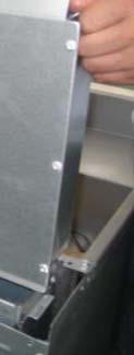


8 Step 3: Flue Installation 1. Unpack the flue box and flue wrap 2. Slide the flue box over the flue and secure it with the two self-tapping screws using a 5/16 socket 3. Slide the flue wrap over the flue 8

 and construction.")


9 4. Secure it with four self-tapping screws two on the back and one on each side using a 5/16 socket Step 4: Check Clearances and Ventilation Select a firm, level location for your fryer. Leave clearance, whenever possible, so that access from the rear is possible to permit cleaning. If the unit is to be set on non-combustible flooring, such as a concrete slab, 3 inches minimum toe room must be provided to prevent restriction of the air opening in the bottom of the unit.! WARNING There must be adequate clearance between fryer(s) and construction. Clearance must also be provided in front for servicing and for operation. Minimum Clearances: From Comb Sides Rear bustible Cons 6 inches 6 inches struction ALL GAS FLOOR MODEL FRYERS SHALL BE INSTALLED WITH AT LEAST A 16 INCH SPACE BETWEEN THE FRYER AND SURFACE FLAMES FROM ADJACENT EQUIPMENT. A FLAME GUARD IS ACCEPTABLE IF ALLOWED UNDER LOCALL CODE. No additional side and rear clearance is required for service as the fryer is serviceable from the front.! WARNING Improper ventilation can result in personal injury or death. Ventilation that fails to properly remove flue products can cause headaches, drowsiness, nausea, or could result in death. Unit Must be installed under a ventilation hood All units must be installed in such a manner that the flow of combustion and ventilation air is not obstructed. Provisions for adequate air supply must also be provided. Do NOT obstruct the bottom front of the unit, as combustion air enters through this area. Be sure to inspect and clean the ventilation system according to the ventilation equipment manufacturer s instructions. 9
10 Due to the variety of problems that can be caused by outside weather conditions, venting by canopies or wall fans is preferred over any type of direct venting. It is recommended that a canopy extend 6" past the appliance and the bottom edge be located 6'6" from the floor. Filters should be installed at an angle of 45 or more from the horizontal. This position prevents dripping of grease and facilitates collecting the run-off grease in a drip pan, unusually installed with a filter. A strong exhaust fan tends to create a vacuum in the room and may interfere with burner performance or may extinguish pilot flames. Fresh air openings approximately equal to the fan area will relieve such a vacuum. In case of unsatisfactory performance on any appliance, check the appliance with the exhaust fan in the OFF position. Do this only long enough to check equipment performance, then turn hood back on and let it run to remove any exhaust that may have accumulated during the test. The exhaust fan should be installed at least 2 feet above the vent opening at the top of the fryer. Make sure all ventilation meet local code requirement This unit is not intended to be connected directly to an outside flue. Step 5:Gas connection A 3/4" male NPT line for the gas connection is located near the lower right rear corner of the fryer. The serial plate (located inside the front door of the fryer) indicates the type of gas the unit is equipped to burn (natural gas or propane). The fryer should be connected ONLY to the type of gas for which it is equipped. A circuit diagram is located inside the front door of the fryer. This equipment is adjusted at the factory; however, pilot height should be checked at installation and adjusted, if necessary. For orifice sizes and pressure regulator settings, see the chart on page 4. If the fryer is being installed at over 2,000 feet altitude and that information was not specified when ordered, contact the appropriate authorized Service Representative or the Service Department. Failure to install with proper orifice sizing will result in poor performance and may void the warranty. If applicable, the vent line from the gas appliance pressure regulator shall be installed to the outdoors in accordance with local codes or, in the absence of local codes, with the National Fuel Gas Code, ANSI Z223.1, Natural Gas Installation Code, CAN/CGA-B149.1, or the Propane Installation Code, CAN/CGA- B149.2, as applicable. An adequate gas supply is imperative. Undersized or low pressure lines will restrict the volume of gas necessary for satisfactory performance. A combination gas valve and pressure regulator, which is provided with each unit, is set to maintain a 4" W.C. manifold pressure for natural gas or 10.0" W.C. manifold pressure for propane gas. However, to maintain these conditions the pressure on the supply line, when all units are operating simultaneously, should not drop below 7" W.C. for natural gas or 11" W.C. for propane gas. Fluctuations of more than 25% on natural gas or 10% on propane gas will create problems and affect burner operating characteristics. A 1/8" tap to measure the manifold pressure is located on the combination gas valve, which is on the burner manifold located directly below the burners inside the cabinet. Purge the supply line to clean out dust, dirt, or other foreign matter before connecting the line to the unit. It is recommended that an individual manual shutoff valve be installed in the gas supply line to the unit. Use pipe joint compound that is suitable for use with both natural and LP gas on all threaded connections. 10
11 ! CAUTION ALL PIPE JOINTS AND CONNECTIONS MUST BE TESTED THOROUGHLY FOR GAS LEAKS. USE ONLY SOAPY WATER FOR TESTING ON ALL GASES. NEVER USE AN OPEN FLAME TO CHECK FOR GAS LEAKS. ALL CONNECTIONS MUST BE CHECKED FOR LEAKS AFTER THE UNIT HAS BEEN PUT INTO OPERATION. TEST PRESSURE SHOULD NOT EXCEED 14" W.C.! CAUTION THIS APPLIANCE AND ITS INDIVIDUAL COMBINATION GAS VALVE MUST BE DISCONNECTED FROM THE GAS SUPPLY PIPING SYSTEM DURING ANY PRESSURE TESTING OF THAT SYSTEM AT TEST PRESSURES IN EXCESS OF 14 WC (1/2 PSIG or 3.45 kpa). If the incoming gas pressure is in excess of 14"WC (1/2PSI, 3.45 kpa), a proper step-down regulator will be required. See PHOTO 1 for LP application Connect the gas supply directly to the 3/4" male NPT connector located near the lower left rear corner of the fryer. When tightening the supply pipe, be sure to hold the mating connector extending from the unit securely with a wrench. This will prevent any damage or distortion to the internal piping and controls of the unit. After connecting the gas supply, check again that the fryer is level. Use a long spirit level four ways; across the front and rear of the frypot, and along each edge. 11

12 PHOTO 1 OPERATION LIGHTING! CAUTION IF YOU SMELL GAS DURING THE LIGHTING PROCEDURE, IMMEDIATELY SHUT OFF THE GAS SUPPLY UNTIL THE LEAK HAS BEEN CORRECTED. Open the burner compartment door and do the following: 1. Turn thermostat to OFF 2. Press down the knob of the combination gas valve, turn it counterclockwise to the PILOT position (shown), and continue to press the knob down. Robert Shaw 7000BMVR Honeywell VS While pressing the knob down, use a lit match to ignite the pilot. Continue to press the knob down for about 30 seconds. If the pilot does not stay lit when the knob is released, repeat the lighting procedure and keep the knob down longer. Adjustment of pilot flame may be necessary. 4. When the pilot stays lit, turn the knob counterclockwise to the ON position. Do not press down on the knob in this step. 5. Do NOT turn the thermostat ON until the frypot is filled with oil or solid shortening. 6. Once the frypot is filled with shortening, set the thermostat to the desired temperature 12
13 FILLING THE FRYPOT 1. Close drain valve completely before filling the frypot. 2. When the fryer is new, fill the frypot with water and clean thoroughly (see Weekly Cleaning on page 15) in order to remove protective coatings and any foreign matter. 3. The recommended solid shortening capacity for the frypot (35, 55 or 75lbs) is described on the serial plate (which is located inside the front door). 4. Remove the basket support frame when filling the frypot with solid shortening. 5. When solid shortening is used, be careful not to bend, break, or twist the thin capillary wires of the sensing elements located in the frypot. 6. Pack solid shortening into the zone below the tubes, all spaces between the tubes, and at least an inch above the top of the tubes before lighting the fryer. If any air spaces are left around the heat tube surfaces when the heat is turned on, the tube surfaces will become red hot, burn the solid shortening, weaken the frypot, and could result in a fire.! CAUTION NEVER ATTEMPT TO MELT A SOLID BLOCK OF SHORTENING ON TOP OF THE HEAT TUBES. NEVER START THE BURNERS WHEN THE FRYPOT IS EMPTY. 7. To prevent burning or scorching the solid shortening, keep the thermostat set at the lowest temperature until all the solid shortening between and above the tubes has been melted. Additional solid shortening can then be added until the desired frying depth has been reached. 8. Replace the basket support frame over the frypot heat tubes. SHUTDOWN PROCEDURE Standby: Turn knob on the combination gas valve to the PILOT position. At this setting, only the pilot burner will remain ignited. Complete Shutdown: Turn knob on the combination gas valve clockwise, press down on the knob and continue to turn to the OFF position. RELIGHTING! WARNING In the event of a main burner ignition failure, a five minute purge period must be observed prior to reestablishing the ignition source. 1. Shut off all gas. 2. Wait five minutes. 3. Follow the Lighting procedure described on page 12. AUTOMATIC PILOT VALVE The Automatic Pilot Valve provides an automatic safety shutoff for the fryer when the pilot flame is extinguished. When the pilot flame is burning, the valve is held open electromagnetically by the electrical current from a thermopile in the pilot flame. When the pilot flame goes out, generation of current ceases and the valve closes automatically. 13
14 HIGH LIMIT CONTROL Gas floor model fryers are equipped with a secondary heat control that prevents the oil temperature from rising above 450 F. (Because of the accuracy tolerance of the sensor, the oil temperature may reach as high as 475 F.) In the event the fryer shuts down due to this condition, the oil must be cooled to below 400 F before the pilot burner can be re-ignited. When the oil has cooled, use the Lighting procedure on page 12 to place the fryer back in operation. If the problem persists, contact your local Service Representative or the Service Department. COOKING HINTS USER TIPS Smoking oil means that the temperature is too high, or that the oil has broken down. Gum in frypot denotes a need for thorough cleaning (see Weekly Cleaning on page 15) Use different oil for oily foods (mackerel, nutmeg, etc.) than for foods with water-soluble flavors (potatoes, onions, etc.). Taste cool oil for quality. Replace it regularly. Poor oil cannot produce good food. CLEANING The equipment is constructed with the best quality materials and is designed to provide durable service when properly maintained. To expect the best performance, your equipment must be maintained in good condition and cleaned daily. Naturally, the frequency and extent of cleaning depends on the amount and degree of usage. Following daily and more extensive periodic maintenance procedures will increase the life of your equipment. Climatic conditions (e.g., salt air) may result in the need for more thorough and more frequent cleaning in order to keep equipment performing at optimal levels.! WARNING: BURN HAZARD If necessary to move the fryer for cleaning, etc., drain oil first to avoid death or serious injury.! WARNING If disconnection of the restraint is necessary to move the appliance for cleaning, etc., reconnect it when the appliance is moved to it originally installed position. DAILY CLEANING 1. Turn thermostat knob to OFF position. 2. Place hot-oil in a safe container under the drain and drain the frypot completely. 3. Remove the basket support frame (if applicable) and flush out any sediment remaining in the frypot with a little hot oil. 14
15 4. Wipe off the basket support frame and the inside of the frypot with a clean cloth.! CAUTION SOME AREAS OF THE FRYPOT MAY BE HOT! 5. Close drain valve and strain the oil back into the frypot through several thicknesses of cheesecloth, or filter it back using a filter machine. 6. Replace the basket support frame (if applicable) 7. Add oil or shortening to MIN oil level mark on rear of frypot. 8. To resume cooking, turn the combination gas valve knob to ON position. WEEKLY CLEANING 1. Follow steps 1 through 4 of the Daily Cleaning procedure (see previous section). 2. Close drain valve and fill frypot with a solution of warm water and boil-out compound 3. Relight the fryer and bring the solution to a gentle boil for at least five minutes. 4. Turn off main burners and let the solution stand until the gum deposits are softened and the carbon spots and burned grease spots can be rubbed off. 5. Scrub the frypot walls and heat tubes, then drain out frypot and rinse it with clean water. 6. Refill the frypot with clean water and boil again. 7. Turn off gas and drain and rinse well until clean. 8. Wipe dry with a clean cloth. 9. Refill as specified in the Filling the Frypot section (see page 13). MONTHLY CLEANING 1. Perform the Weekly Cleaning procedure (see previous section). 2. Clean around burner and orifices if lint has accumulated. 3. Visually check that burner carry-over ports are unobstructed. CLEANING STAINLESS STEEL SURFACES To remove normal dirt, grease and product residue from stainless steel use ordinary soap and water (with or without detergent) applied with a sponge or cloth. Dry thoroughly with a clean cloth. Never use vinegar or any corrosive cleaner. To remove grease and food splatter or condensed vapors that have baked on the equipment apply cleanser to a damp cloth or sponge and rub cleanser on the metal in the direction of the polishing lines on the metal. Rubbing cleanser, as gently as possible, in the direction of the polished lines will not mar the finish of the stainless steel. NEVER RUB WITH A CIRCULAR MOTION. Soil and burnt deposits that do not respond to the above procedure can usually be removed by rubbing the surface with SCOTCH-BRITE scouring pads or STAINLESS scouring pads. DO NOT USE ORDINARY STEEL WOOL, as any particles left on the surface will rust and further spoil the appearance of the finish. NEVER USE A WIRE BRUSH, STEEL SCOURING PADS (EXCEPT STAINLESS), SCRAPER, FILE OR OTHER STEEL TOOLS. Surfaces that are marred collect dirt more rapidly and become more difficult to clean. Marring also increases the possibility of corrosive attack. Refinishing may then be required. Darkened areas, called heat tint, sometimes appear on stainless steel surfaces where the area has been subjected to excessive heat. These darkened areas are caused by thickening of the protective surface of the stainless steel and are not harmful. Heat tint can normally be removed by the above cleaning techniques, but tint which does not respond to that procedure calls for a vigorous scouring in the direction of the polish lines, using SCOTCH-BRITE scouring pads or a STAINLESS scouring pad in combination with a powered 15
16 cleanser. Heat tint action may be lessened by not applying or by reducing, heat to equipment during slack periods. S SERVI CE (FOR AUTHORIZED SERVICE TECHNICIAN ONLY) NOTICE Warranty will be void and the manufacturer is relieved of all liability if: (A) Service work is performed by other than a qualified technician (see page 30 for detail) OR (B) Other than approved replacement parts are installed.! WARNING Adjustments and servicee work may be performed only by a qualified technician who is experienced in, and knowledgeable with, the operation of commercial gas cooking equipment. However, to assure your confidence, contactt your Servicee Representative for reliable service, dependable advice or other assistance, and for genuine factory parts. All units are adjusted at the factory. In case of problems in operation at initial installation, check type of gas and manifold pressure and compare with information listed on the serial plate. A mill voltage circuit diagram is located inside the front door of the fryer, and also on page 19. CHECKING AND ADJUSTING MAIN BURNERS The main burners should burn with a steady CORE PRO, and the inner cone of the flame from each port should be about 3/4" long. The flame from each main burner should enter each heat tube without touching the front of the frypot or the sides, top, or bottom of each tube. Yellow Tips (too little air or too much gas) Blowing or Lifting Flames (too much air) Normal Flame 16
17 CHECKING AND ADJUSTING PRESSURE REGULATOR The combination gas valve (includes pressure regulator) is factory set at 4" W.C. for natural gas and 10" W.C. for propane gas. To check the manifold pressure, do the following: 1. Turn thermostat OFF and combination gas valve knob to the PILOT setting. 2. Remove pressure tap plug from burner manifold located directly below the burners in the cabinet. 3. Install a fitting appropriate to connect a manometer. 4. Turn combination gas valve to ON position and thermostat to ON. The burners will ignite. Be certain that sufficient oil is covering the tubes. 5. With burners on, read manometer. 6. If the manometer does not read 4" W.C. for natural gas, or 10" W.C. for propane gas, adjust regulator. 7. Remove regulator adjustment screw cap (see diagram on page 15). 8. With small screwdriver rotate adjustment screw CLOCKWISE to increase or COUNTERCLOCKWISE to decrease pressure. Be sure to adjust with burners ON. 9. Turn thermostat OFF and set combination gas valve knob to PILOT position. 10. Remove manometer and replace pressure tap plug. 11. Replace adjustment screw cap. CHECKING AND ADJUSTING CALIBRATION OF THERMOSTAT All thermostat controls are carefully calibrated at the factory (i.e., the dial is properly set to control appliance temperatures accurately). Only a qualified appliance service technician should perform this adjustment. 1. To check appliance temperatures, use a thermocouple-type temperature test instrument or reliable thermometer. Place the thermocouple of test instrument or thermometer in the center of the frypot. 2. Turn the control dial to the temperature setting requiring the greatest accuracy. Allow enough time for temperature to stabilize, or until several temperature readings are identical. 3. Recalibrate if setting and actual temperature differ by more than 10 F. 4. Remove dial from dial shaft B. Be careful that dial shaft does not rotate in either direction (which would change the dial setting). 5. Hold dial shaft B steady and with a screwdriver turn calibration screw A clockwise to decrease the temperature, or counterclockwise to increase the temperature. 6. Replace dial. Let the appliance operate until the temperature has stabilized before a final check is made to determine whether or not the calibration has been corrected. 7. Once correct, seal the calibration screw with glyptol. 17

18 CHECKING AND ADJUSTING AUTO SAFETY PILOT The pilot flame should surround the thermopile for 1/2". It must be large and sharp enough to cause the thermopile to glow a dull red, or sufficient to hold the safety valve open. 1. Remove pilot adjustment cap 2. Adjust pilot key to provide properly sized flame shown in diagram B. Diagram A shows an improperly adjusted pilot 3. Replace pilot adjustment cap. TROUBLESHOOTING Problem Burners do not come on Pilot will not stay ignited Pilot produces carbon deposits Burners produce carbon deposits Likely Cause Gas supply to unit off. Combination gas valve is in OFF or PILOT position. Pilot not ignited. Thermostat not ON. Combination gas valve is in OFF position. Pilot gas not adjusted properly. Gas supply to unit off. Bad thermopile. Dirty thermopile connections at combination gas valve or high limit. Clogged orifice. Draft condition. Air in gas line. Improper ventilation system. Unit connected to wrong gas supply. Pressure not adjusted correctly. Pilot gas not adjusted correctly. Wrong size orifices. Connected to wrong gas supply. Pressure not adjusted correctly. Flue obstructed. NOTE: Vibrations or shock caused by shaking or pounding baskets on top surface or by slamming door may cause Hi-Limit Control Switch to open. If this condition persists, additional cushioning may be added to the rubber grommets supporting this control to absorb these shocks. 18
19 Wiring Diagram 19
20 PARTS NOTICE INSTALLATION OF OTHER THAN GENUINE PARTS WILL VOID THE WARRANTY ON THIS EQUIPMENT. The serial plate is located inside the front door on the left side. Replacement parts may be ordered either through a Authorized Parts Distributor or a Authorized Service Agency. When ordering parts, please supply the Model Number, Serial Number, Part Number, and Description. Index of Part Diagrams Page Number Description 21 Gas Parts for 3, 4 and 5 tube fryer 22 Tank Parts for 3, 4 and 5 tube fryer 22 Other parts (Legs, Casters, baskets, doors, magnet) 20
21 Gas Parts for Fryer (3 tube shown) Key Part Number Qty Description 1 FS Knob, thermostat 3 FS Thermostat Fryer, regulating FS Combination Valve (Nat)_Robertshaw 4 FS Combination valve (LP)_Robertshaw 4 FS Combination Valve (Nat)_Honeywell 4 FS Combination valve (LP)_Honeywell 5 FS Tube, flexible, 1/4", 23in, pilot 10 FS ea Burner, Fryer 11 FS Thermopile FS ea Orifice # 39 (Nat) (as part of kit ) 12 FS ea Orifice # 52 (LP) (as part of kit ) 14 FS Thermostat, High limit 450F 15 FS Pilot LP 15 FS Pilot NG 16 FS ea Orifice extension 21
Apollo Series Fryers
 TABLE OF CONTENTS OPERATOR S MANUAL Apollo Series Fryers Model A-3-NAT A-3-LP (3 Burner Fryer) Model A-4-NAT A-4-LP (4 Burner Fryer) Model A-5-NAT A-5-LP ( 5 Burner Fryer) Improper installation, adjustment,
OPERATOR S MANUAL Sierra Fryers
 OPERATOR S MANUAL Sierra Fryers Model SRF-35/40 (3 Burner Fryer) Improper installation, adjustment, alteration, service or maintenance can cause property damage, injury or death. Read the installation,
R A N G E C O R P. OPERATOR S MANUAL. F Series Fryers. Model F4 (4 Burner Fryer) WARNING
 WARNING") Therma-Tek Fryers TABLE OF CONTENTS R A N G E C O R P. OPERATOR S MANUAL F Series Fryers Model F3 (3 Burner Fryer) Model F4 (4 Burner Fryer) Model F5-18 ( 5 Burner Fryer) WARNING Improper installation,
Therma-Tek Fryers TABLE OF CONTENTS R A N G E C O R P. OPERATOR S MANUAL F Series Fryers Model F3 (3 Burner Fryer) Model F4 (4 Burner Fryer) Model F5-18 ( 5 Burner Fryer) WARNING Improper installation,
Sectional Deep Fryer
 IMPORTANT FOR FUTURE REFERENCE Please complete this information and retain this manual for the life of the equipment: Model #: Serial #: Date Purchased: OPERATOR S MANUAL Model P16-FR45 and P20-FR65 Sectional
Thor Gas Fryer Installation and Operation Instructions
 Thor Gas Fryer Installation and Operation Instructions Model: GL165-P, GL165-N, GL166-P, GL166-N IMPORTANT FOR FUTURE REFERENCE Please complete this information and retain this manual for the life of the
F SERIES FRYERS. Owner s Manual Installation Guide. Model F4 (4 Burner Fryer)
") F SERIES FRYERS Owner s Manual Installation Guide Model F3 (3 Burner Fryer) Model F4 (4 Burner Fryer) Model F5 (5 Burner Fryer) Improper installation, adjustment, alteration, service or maintenance can
F SERIES FRYERS Owner s Manual Installation Guide Model F3 (3 Burner Fryer) Model F4 (4 Burner Fryer) Model F5 (5 Burner Fryer) Improper installation, adjustment, alteration, service or maintenance can
Owner s Guide Installation & Operation
 Owner s Guide Installation & Operation Hot Top HHT Series Hestan Commercial Corporation 3375 E. La Palma Ave Anaheim, CA 92806 (888) 905-7463 RETAIN THIS MANUAL FOR FUTURE REFERENCE P/N 002130 REV 1 IMPORTANT
Owner s Guide Installation & Operation
 Owner s Guide Installation & Operation Fryer HFR Series Hestan Commercial Corporation 3375 E. La Palma Ave Anaheim, CA 92806 (888) 905-7463 RETAIN THIS MANUAL FOR FUTURE REFERENCE P/N 002137 REV 1 IMPORTANT
Radiant Salamander Broiler
 Owner s Manual IMPORTANT FOR FUTURE REFERENCE Please complete this information and retain this manual for the life of the equipment: Model #: Serial #: Date Purchased: Radiant Salamander Broiler Model
INSTALLATION & OPERATION MANUAL
 INSTALLATION & OPERATION MANUAL EF SERIES ECONOFRY GAS FRYERS MODEL EF3 EF4 EF5 ML-52099 ML-114943 ML-114944 MODEL EF3 For additional information on Vulcan-Hart or to locate an authorized parts and service
Radiant Steakhouse Broiler
 Owner s Manual IMPORTANT FOR FUTURE REFERENCE Please complete this information and retain this manual for the life of the equipment: Model #: Serial #: Date Purchased: Radiant Steakhouse Broiler Models
OWNERS MANUAL INSTALLATION, OPERATION, & MAINTENANCE INSTRUCTIONS
 OWNERS MANUAL INSTALLATION, OPERATION, & MAINTENANCE INSTRUCTIONS 1128 Sherborn Street Corona, CA 92879-2089 (951) 281-1830 (951) 281-1879 IPC SERIES PASTA COOKER All Imperial Mfg. Co. equipment is manufactured
USER MANUAL Gas Countertop Charbroilers
 Gas Countertop Charbroilers REVISED 2/209 382799 LAVA BRIQUETTE MODELS: 35CLCPG5NL, 35CLCPG24NL, 35CLCPG36NL, 35CLCPG48NL, 35CLCPG60NL, 35CLCPG72NL Congratulations on your purchase of Cooking Performance
PRO SERIES GAS FRYERS OWNER S MANUAL
 PRO SERIES GAS FRYERS OWNER S MANUAL MODELS: PF-1 PRO-FRYER, PF2 DUAL PRO-FRYER REVISED OCTOBER, 2009 *PLEASE RETAIN FOR FUTURE REFERENCE This appliance has been tested according to ANSI Z83.116-2009/CSA1.86-2009.
INSTALLATION AND OPERATION MANUAL GAS SKILLETS MODELS: GTS-30 GTS-40
 INSTALLATION AND OPERATION MANUAL GAS SKILLETS MODELS: GTS-30 GTS-40 CROWN FOOD SERVICE EQUIPMENT LTD. 70 OAKDALE ROAD, DOWNSVIEW, (TORONTO), ONTARIO, CANADA, M3N 1V9 TELEPHONE: (416) 746-2358, FAX: (416)
GPC PASTA PRO INSTALLATION & USER OPERATION MANUAL
 GPC-14/18/20 GPC PASTA PRO INSTALLATION & USER OPERATION MANUAL GPC-18 shown with optional rinse station. NOTICE! After installation of your equipment, immediately contact your local gas supplier to obtain
Owner s Guide Installation & Operation
 Owner s Guide Installation & Operation Char Broiler HCH Series Hestan Commercial Corporation 3375 E. La Palma Ave Anaheim, CA 92806 (888) 905-7463 RETAIN THIS MANUAL FOR FUTURE REFERENCE P/N 002134 REV
PLEASE RETAIN THIS MANUAL FOR FUTURE REFERENCES. This equipment is design engineered for commercial use only
 OWNER S MANUAL INSTALLATION OPERATION MAINTENANCE FRYER SRF-40/50 All equipment manufactured by SIERRA CORP. is for use with the type of gas specified on the rating plate and for installation will be in
INSTALLATION AND OPERATION MANUAL GAS FIRED STEAMERS MODELS: GSX-5HE GSX-7HE GSX-10HE GSX-16HE
 INSTALLATION AND OPERATION MANUAL GAS FIRED STEAMERS MODELS: GSX-5HE GSX-7HE GSX-10HE GSX-16HE CROWN FOOD SERVICE EQUIPMENT LTD. 70 OAKDALE ROAD, DOWNSVIEW, (TORONTO), ONTARIO, CANADA, M3N 1V9 TELEPHONE:
INSTALLATION & OPERATIONAL MANUAL
 INSTALLATION & OPERATIONAL MANUAL LG SERIES GAS FRYERS MODELS: LG300 LG400 LG500 ML-136528 ML-136622 ML-136643 For additional information on Vulcan-Hart or to locate an authorized parts and service provider
USER MANUAL Gas Step Up Hot Plate
 USER MANUAL Gas Step Up Hot Plate MODELS: CK HPSU, CK HPSU, CK HPSU 0 / 07 IMPORTANT FOR FUTURE REFERENCE Please complete this information and retain this manual for the life of the equipment. For Warranty
OPERATOR S MANUAL Heavy Duty Counterline
 IMPORTANT FOR FUTURE REFERENCE Please complete this information and retain this manual for the life of the equipment: Model #: Serial #: Date Purchased: OPERATOR S MANUAL Heavy Duty Counterline Griddle
STAR-MAX PROPANE GAS GRIDDLE
 Star Manufacturing International Inc. 10 Sunnen Drive St. Louis, MO 63143 Phone: (314) 781-2777 Fax: (314) 781-3636 Installation and Operating Instructions 2M-Z3793 Rev. B 3/28/03 STAR-MAX PROPANE GAS
R-RCM & R-RSB SERIES
 R-RCM & R-RSB SERIES CHEESEMELTER & SALAMANDER BROILERS INSTALLATION - OPERATION - MAINTENANCE CHEESEMELTERS R-RCM-24 R-RCM-36 R-RCM-48 R-RCM-60 SALAMANDERS R-RSB-24 R-RSB-36 R-RSB-48 Telephone: (802)
INSTALLATION, OPERATION & MAINTENANCE AVANTCO SERIES 177AG OWNER S MANUAL
 INSTALLATION, OPERATION & MAINTENANCE AVANTCO SERIES 177AG OWNER S MANUAL Manual Griddles: Radiant Charbroilers: Hot Plates: 177AG24MG 177AG36MG 177AG24RC 177AG36RC 177AGR212 All equipment manufactured
GAS FIRED STEAMER Models SX-34GCR and SX-55GCR
 IMPORTANT FOR FUTURE REFERENCE Please complete this information and retain this manual for the life of the equipment: Model #: Serial #: Owner s Manual Date Purchased: GAS FIRED STEAMER Models SX-34GCR
MODELS: JGM, JGGM, JGT, JGTS, JGTSD, JGTSDS, JGGT, JGGTS, JTYG GRIDDLES AND JHP, JHPE HOT PLATES
 Jade Range LLC, A Middleby Company 2650 Orbiter Ave. Brea, CA 92821 Telephone (714) 961-2400 FAX (714) 961-2550 MODELS: JGM, JGGM, JGT, JGTS, JGTSD, JGTSDS, JGGT, JGGTS, JTYG GRIDDLES AND JHP, JHPE HOT
Gas Countertop Fryer lb Model lb Model NG and LPG Models
 Gas Countertop Fryer 35-40 lb Model 45-50 lb Model NG and LPG Models This manual contains important information regarding your unit. Please read this manual thoroughly prior to equipment set-up, operation
SR42G/52G Series Gas Fryers
 SR42G/52G Series Gas Fryers Installation & Operation Manual PRINTED IN THE UNITED STATES For Service, Call (318) 865-1711 Dean, 8700 Line Avenue, PO Box 51000, Shreveport, Louisiana 71135-1000 Shipping
STAR-MAX GAS GRIDDLES MODELS 615MA 624MA 636MA 648MA 615TA 624TA 636TA 648TA 624TSPA 636TSPA 648TSPA
 Star Manufacturing International Inc. 10 Sunnen Drive St. Louis, MO 63143 Phone: (314) 781-2777 Fax: (314) 781-3636 Installation and Operating Instructions 2M-Z1351 Rev. B 4/23/04 STAR-MAX GAS GRIDDLES
TRI-STAR INC SOUTH STANDARD AVENUE, SANTA ANA, CA Ph: Fax: MODEL #. OWNER S MANUAL
 TRI-STAR INC 2205 SOUTH STANDARD AVENUE, SANTA ANA, CA 92707 Ph: 714 424 9380 Fax: 714 424 9385 MODEL #. OWNER S MANUAL INSTALLATION OPERATION MAINTENANCE All equipments manufactured by Tri-star Inc. for
ULTRA-MAX GAS RADIANT CHARBROILER. ULTRA-MAX GAS LAVA ROCK CHARBROILER MODELS 8024CBB, 8036CBB, 8048CBB, 8060CBB, and 8072CBB
 Star Manufacturing International Inc. 10 Sunnen Drive St. Louis, MO 63143 Phone: (314) 678-6303 Fax: (314) 781-2714 Installation and Operating Instructions 2M-Z20327 Rev. A 10/05/15 ULTRA-MAX GAS RADIANT
INSTALLATION & OPERATION MANUAL GAS CHARBROILERS
 INSTALLATION & OPERATION MANUAL GAS CHARBROILERS MODELS VCCB25 VCCB36 VCCB47 VCCB60 VCCB72 VCCB47 SCB25 SCB36 SCB47 SCB60 SCB72 SCB47 ITW Food Equipment Group, LLC 3600 North Point Blvd. Baltimore, MD
OPERATING, INSTALLATION, SERVICE & PARTS MANUAL FOR MEDIUM DUTY GAS CHAR BROILERS MGB-A SERIES
 OPERATING, INSTALLATION, SERVICE & PARTS MANUAL FOR MEDIUM DUTY GAS CHAR BROILERS MGB-A SERIES VULCAN-HART COMPANY, P.O. BOX 696, LOUISVILLE, KY 40201-0696, TEL. (502) 778-2791 FORM 990503 (09-88) ! IMPORTANT
Instruction Manual for the Globe Gas Fryer Models: GFF35G, GFF50G, GFF80G and GFF35PG, GFF50PG, GFF80PG
 Serial #: GFF35G/GFF35PG Instruction Manual for the Globe Gas Fryer Models: GFF35G, GFF50G, GFF80G and GFF35PG, GFF50PG, GFF80PG For Service on Your Gas Fryer: 1. Visit our website at www.globefoodequip.com
CINCINNATI, OH USA
 INSTRUCTION MANUAL Part No. 89731 Revised October 1997 CINCINNATI, OH 45241-4807 USA GAS SAFETY PRECAUTIONS Instructions on what to do when a user smells gas can be obtained from the local gas supplier.
JADE TACO RANGES MODEL: JTR and JTRB Series JADE STOCK POT RANGES MODEL: JSP Series
 Jade Range LLC, A Middleby Company 2650 Orbiter Ave. Brea, CA 92821 Telephone (714) 961-2400 FAX (714) 961-2550 JADE TACO RANGES MODEL: JTR and JTRB Series JADE STOCK POT RANGES MODEL: JSP Series INSTALLATION,
Marathoner Gold & SilverStar GAS CONVECTION OVENS
 IMPORTANT FOR FUTURE REFERENCE Please complete this information and retain this manual for the life of the equipment: Model #: Serial #: Date Purchased: OPERATOR S MANUAL Marathoner Gold & SilverStar GAS
Thor Gas Fryer Technical Service Manual
 Thor Gas Fryer Technical Service Manual Model: GH110-P, GH110-N,GH111-P,GH111-N IMPORTANT FOR FUTURE REFERENCE Please complete this information and retain this manual for the life of the equipment. For
Marathoner Gold HALF-SIZE ELECTRIC CONVECTION OVENS
 IMPORTANT FOR FUTURE REFERENCE Please complete this information and retain this manual for the life of the equipment: Model #: Serial #: Date Purchased: OPERATOR S MANUAL Marathoner Gold HALF-SIZE ELECTRIC
southbend A MIDDLEBY COMPANY INSTALLATION AND OPERATION MANUAL CG214 (E) CG314 (E) CG414 (E) CG220 (E) CG320 (E) CG325 (E) GAS BOILERS MODELS:
 CG314 (E) CG414 (E) CG220 (E) CG320 (E) CG325 (E) GAS BOILERS MODELS:") INSTALLATION AND OPERATION MANUAL GAS BOILERS MODELS: CG214 (E) CG314 (E) CG414 (E) CG220 (E) CG320 (E) CG325 (E) southbend A MIDDLEBY COMPANY 1100 Old Honeycutt Road Fuquay-Varina, NC 27526 (919) 552-9161
INSTALLATION AND OPERATION MANUAL GAS BOILERS MODELS: CG214 (E) CG314 (E) CG414 (E) CG220 (E) CG320 (E) CG325 (E) southbend A MIDDLEBY COMPANY 1100 Old Honeycutt Road Fuquay-Varina, NC 27526 (919) 552-9161
Using it in an enclosed space can kill you.
 38 X 56 GAS FIRE PIT - OWNER S MANUAL Carlisle Chat Fire Table Base Model # 00GBC7 (6877B) Fits 6877A Carlisle Chat Fire Table Top For Propane and *Natural Gas (*See Page 7) Certified to CSA International
INSTALLATION & OPERATION MANUAL FOR Achiever Charbroilers
 INSTALLATION & OPERATION MANUAL FOR Achiever Charbroilers MODELS MLS VACB20 ML-135285 VACB25 ML-710543 VACB36 ML-710544 VACB47 ML-710545 VACB60 ML-710546 VACB72 ML-135286 www.vulcanhart.com MODELS MLS
Radiant Broilers WARNING
 Owner s Manual IMPORTANT FOR FUTURE REFERENCE Please complete this information and retain this manual for the life of the equipment: Model #: Serial #: Date Purchased: Radiant Broilers 234R P32D-3240 WARNING
User Manual. 110 Cup (55 Cup Raw) Gas Rice Cooker. Model: 177GRCLP, 177GRCNAT 12/2018. Please read and keep these instructions. Indoor use only.
 Gas Rice Cooker. Model: 177GRCLP, 177GRCNAT 12/2018. Please read and keep these instructions. Indoor use only.") 110 Cup (55 Cup Raw) Gas Rice Cooker Intertek 5010781 Conforms to ANSI STD Z83.11-2016 Model: 177GRCLP, 177GRCNAT 12/2018 FOR YOUR SAFETY Do not store or use gasoline or other flammable vapors or liquids
110 Cup (55 Cup Raw) Gas Rice Cooker Intertek 5010781 Conforms to ANSI STD Z83.11-2016 Model: 177GRCLP, 177GRCNAT 12/2018 FOR YOUR SAFETY Do not store or use gasoline or other flammable vapors or liquids
GAS DECK OVENS INSTALLATION & OPERATING MANUAL
 GAS DECK OVENS INSTALLATION & OPERATING MANUAL MODELS: MB42, MB60, MB236, MB260, MB866, SD236, SD248, SD260, SD448, SD660, SD1048, SD1060, SD866, SD10866, WF42, WF60 FOR YOUR SAFETY DO NOT STORE OR USE
Installation and Operation Manual Covering Model 40S, 40C, 40D with Millivolt Gas Valve
 IMPORTANT FOR FUTURE REFERENCE Please complete this information and retain this manual for the life of the equipment: Model #: Serial #: Date Purchased: ENGLISH Installation and Operation Manual Covering
Installer: Leave this manual with the appliance. Consumer: Retain this manual for future reference.
 Installer: Leave this manual with the appliance. Consumer: Retain this manual for future reference. Operating Instructions and Owner s Manual READ INSTRUCTIONS CAREFULLY: Read and follow all instructions.
Operator s Manual CAYENNE GAS COUNTERTOP CHAR BROILER ENGLISH
 NGLISH CAYNN GAS COUNTRTOP CHAR BROILR Thank you for purchasing this Vollrath Counter Top Cooking quipment. Before operating the equipment, read and familiarize yourself with the following operating and
Gas Cooktop Installation, User and Service Instructions GMS 955.1
 Gas Cooktop Installation, User and Service Instructions GMS 955.1 IMPORTANT: SAVE FOR LOCAL ELECTRICAL INSPECTOR S USE. READ AND SAVE THESE INSTRUCTIONS FOR FUTURE REFERENCE. OBSERVE ALL FEDERAL, STATE
MODELS LFP4218/LFP6018 TOP VENT GAS FIREPLACE
 MODELS LFP4218/LFP6018 TOP VENT GAS FIREPLACE PFS APPROVED FOR NATURAL GAS OR PROPANE GAS Z21.50-2014 If your plans do not allow for the venting system as outlined previously in the installing chimney/vent
Installation and Operation Manual Covering Model 35C+, 45C+ with Millivolt Gas Valve
 IMPORTANT FOR FUTURE REFERENCE Please complete this information and retain this manual for the life of the equipment: Model #: Serial #: Date Purchased: ENGLISH Installation and Operation Manual Covering
OWNER S MANUAL INSTALLATION OPERATION MAINTENANCE CONVECTION OVEN MODEL # RDCO-32
 OWNER S MANUAL INSTALLATION OPERATION MAINTENANCE CONVECTION OVEN MODEL # RDCO-32 All Rankin-Delux, Inc. equipment is manufactured for use with the type of gas specified on the rating plate and for installation
INSTALLATION GUIDE Dual Fuel Ranges
 INSTALLATION GUIDE Dual Fuel Ranges Contents Wolf Dual Fuel Ranges......................... 3 Safety Instructions............................ 4 Dual Fuel Range Specifications.................. 5 Dual Fuel
Marathoner Gold & SilverStar ELECTRIC CONVECTION OVENS
 IMPORTANT FOR FUTURE REFERENCE Please complete this information and retain this manual for the life of the equipment: Model #: Serial #: Date Purchased: OPERATOR S MANUAL Marathoner Gold & SilverStar ELECTRIC
Installation/Operating Instructions
 Installation/Operating Instructions Models: 4072-180 24 NG 4072-182 30 NG Outdoor Hearth Kit DO NOT DISCARD INSTALLER: Leave this manual with party responsible for use and operation. OWNER: Retain this
Stone Hearth Pizza Dome Oven
 Stone Hearth Pizza Dome Oven INSTALLATION AND OPERATION MANUAL GAS-FIRED OVEN CAUTION This oven MUST be seasoned before initial use The seasoning procedure takes 6 days, running the oven for at least 8
INSTALLATION OPERATING, AND SERVICE INSTRUCTIONS FOR SUBURBAN DIRECT VENT SEALED COMBUSTION GAS HEATER MODEL GT-10D
 INSTALLATION OPERATING, AND SERVICE INSTRUCTIONS FOR SUBURBAN DIRECT VENT SEALED COMBUSTION GAS HEATER MODEL GT-10D FOR YOUR SAFETY FOR YOUR SAFETY IF YOU SMELL GAS: DO NOT STORE OR USE GASOLINE 1. OPEN
USER MANUAL Stock Pot Range
 Stock Pot Range MODEL: 351CPGSPR18(L/N) 11/2017 This user s manual contains information and guidelines collected from years of industry experience. For optimal safety and efficient operation, please make
INSTALLATION & OPERATION MANUAL
 DRAWER WARMERS CHIP WARMERS MODELS: CHIP WARMERS: 200-1-CW 200-2-CW DRAWER WARMERS: CAFÉ : 200-1R-C 200-2R-C 200-3R-C 200-4R-C CAFE BUILT-IN: 200-1R-BI-C 200-2R-BI-C 200-3R-BI-C 200-3R-BI-C INSTALLATION
INSTALLATION AND OPERATION MAINTENANCE
 INSTALLATION AND OPERATION MAINTENANCE TSF SERIES FRYER OWNER S MANUAL Models: TSF-3540, TSF-4050, TSF-6575 FOR YOUR SAFETY: Do not store or use gasoline or other flammable vapors or liquids in the vicinity
Fig. 1 - Unit PGD4, PGS4, WPG4
 OWNER S MANUAL 14 SEER Single -Package Air Conditioner and Gas Furnace System with R -410A Refrigerant Single Phase 2 to 5 Nominal Tons Three Phase 3 to 5 Nominal Tons PGD4andPGS4SeriesE,WPG4SeriesB Fig.
OWNER'S, SERVICE & INSTRUCTION
 OWNER'S, SERVICE & INSTRUCTION M A N U A L GAS DECK OVENS MODELS 209, 209SS X 309, 309SS 212, 212SS X 312, 312SS 215, 215SS X 315, 315SS IMPORTANT INSTRUCTIONS FOR OVEN INSTALLATION, OPERATION AND MAINTENANCE
Owner s Information Manual
 48ES---A and 48VL---A Comfort and Performance 13 and 14 SEER Single Packaged Air Conditioner and Gas Furnace System With Puron (R---410A) Refrigerant Single and Three Phase 2---5 Nominal Tons (Sizes 24---60)
INSTALLATION & OPERATION MANUAL
 INSTALLATION & OPERATION MANUAL GS, GL & GT SERIES FULLY STEAM JACKETED GAS KETTLES MODEL GS25E GS30E GL40E GS60E GL80E GT100E GT5E GT150E ML-52633 ML-52634 ML-52635 ML-52660 ML-52637 ML-52638 ML-52639
Installation, Operation, and Maintenance Manual For McDonald's Gas Fryer Counter Top Models 12MCD
 Installation, Operation, and Maintenance Manual For McDonald's Gas Fryer Counter Top Models 12MCD NOTICES There are three different types of notices that you should be familiar with, a NOTICE, CAUTION,
USER S, MAINTENANCE and SERVICE INFORMATION MANUAL
 CONTENTS SAFETY INFORMATION................ 2 FOR YOUR SAFETY...................... 2 SYSTEM OPERATION.................. 2 THERMOSTATS.......................... 2 INTERMITTENT IGNITION DEVICE..........
USER S INFORMATION MANUAL (2,4)SG13B
SG13B") USER S INFORMATION MANUAL (2,4)SG13B Series Gas Heating/Electric Cooling Package Unit Congratulations......your outdoor heating/cooling package unit is a valuable piece of equipment, designed and manufactured
USER S INFORMATION MANUAL (2,4)SG13B Series Gas Heating/Electric Cooling Package Unit Congratulations......your outdoor heating/cooling package unit is a valuable piece of equipment, designed and manufactured
CYLINDER NOT INCLUDED
 OPERATING INSTRUCTIONS AND OWNER S MANUAL Model # HS125NG / MH125LP / HS125LP READ INSTRUCTIONS CAREFULLY: Read and follow all instructions. Place instructions in a safe place for future reference. Do
INSTALLATION INSTRUCTIONS AND OWNER S MANUALS
 INSTALLATION INSTRUCTIONS AND OWNER S MANUALS OUTDOOR PATIO HEATER Model 920-0049 WARNING: For Outdoor Use Only IMPORTANT A0Y09P- Read this manual carefully before assembling, using or servicing this heater.
INSTRUCTION MANUAL. Full Size Gas Convection Oven
 INSTRUCTION MANUAL Full Size Gas Convection Oven This manual contains important information regarding your unit. Please read this manual thoroughly prior to equipment set-up, operation and maintenance.
USER S INFORMATION MANUAL
 USER S INFORMATION MANUAL UPFLOW & DOWNFLOW/HORIZONTAL CONDENSING GAS FURNACES SAFETY Recognize this symbol as an indication of Important Safety Information If not installed, operated and maintained in
GAS COOKTOP INSTALLATION INSTRUCTIONS
 INSTALLATION AND SERVICE MUST BE PERFORMED BY A QUALIFIED INSTALLER. IMPORTANT: SAVE FOR LOCAL ELECTRICAL INSPECTOR'S USE. READ AND SAVE THESE INSTRUCTIONS FOR FUTURE REFERENCE. WARNING If the information
INSTALLATION MANUAL. Free Standing Ranges. RCS (Open/Sealed) RNB RPB Platinum Precious Metals 1
 RNB RPB Platinum Precious Metals 1") INSTALLATION MANUAL Free Standing Ranges RCS (Open/Sealed) RNB RPB Platinum Precious Metals 1 750163 BlueStar Free Standing Range Installation Manual MODELS RCS, RPB, RNB, Platinum, Precious Metals THIS
INSTALLATION MANUAL Free Standing Ranges RCS (Open/Sealed) RNB RPB Platinum Precious Metals 1 750163 BlueStar Free Standing Range Installation Manual MODELS RCS, RPB, RNB, Platinum, Precious Metals THIS
INSTALLATION & OPERATION MANUAL
 INSTALLATION & OPERATION MANUAL V SERIES FOOD HOLDING & TRANSPORTATION CABINETS MODELS: VB90 VB96 VB150 VBP5I VBP7I VBP13I VBP15I VBP33 VBP77I VBS15 VHA9 VHA18 VHDP5 VHFA9 VHFA18 VHP3 VHP7 VHP8 VHP15 VHP20
Super Runner Series Electric Fryers
 Super Runner Series Electric SR114E Super Runner Series Electric Fryers Installation & Operation Manual NON-CE & Dean, a member of the Commercial Food Equipment Service Association, recommends using CFESA
GAS COOKTOP INSTALLATION INSTRUCTIONS BEFORE YOU BEGIN. IMPORTANT Save these instructions for local electrical inspector s use.
 GAS COOKTOP INSTALLATION INSTRUCTIONS Please read this guide thoroughly before installation. To contact LG Electronics, 24 hours a day, 7 days a week: 1-800-243-0000 (U.S.A.) 1-888-542-2623 (Canada) Or
DESIGN CLASS FUNCTION
 PROFESSIONAL QUALITY COOKING EQUIPMENT INSTALLATION MANUAL FOR PERFORMER SLIDE-IN COOK TOPS MODEL NUMBERS: AROBSCT-424, AROBSCT-242GD, AROBSCT-24X2GR, AROBSCT-430, AROBSCT-636, AROBSCT-436GD, AROBSCT-436GR,
SERIES: BPF 3540, 4050, & 6575
 OPERATION MANUAL RESTAURANT SERIES FULL-SIZE GAS FRYERS SERIES: BPF 3540, 4050, & 6575 BUILT BY CRAFTSMEN. TESTED BY TIME. FRYERS Models: BPF-3540, BPF-4050, BP-6575 Bakers Pride Oven Company, LLC is a
21 20 LITER GAS FRYER FFA3200 INSTALLATION AND SERVICING.
 21 20 LITER GAS FRYER FFA3200 INSTALLATION AND SERVICING www.anvilworld.com 20 ALL ANVIL EQUIPMENT COMES WITH A ONE YEAR WARRANTY ON COMPONENTS AND DEFECTIVE WORKMANSHIP. www.anvilworld.com 19 20 LITER
PAULIN PRODUCTS INDOOR HEATER
 PAULIN PRODUCTS INDOOR HEATER OWNER S MANUAL AND OPERATING INSTRUCTIONS May be used with a disposable 1 lb. propane cylinder: - for emergency indoor home heating - for indoor use in commercial enclosures,
INSTALLATION & OPERATION MANUAL
 CBFT SERIES CORRECTIONAL HEATED HOLDING CABINETS INSTALLATION & OPERATION MANUAL MODELS: CBFT CBFTHS ML-152028-0000Z ML-152029-0000Z VULCAN 3600 NORTH POINT BLVD. DIVISION OF ITW FOOD EQUIPMENT GROUP,
southbend OWNER'S MANUAL INSTALLATION USER'S GUIDE SERVICE PARTS STATIONARY GAS SELF CONTAINED STEAM KETTLES
 southbend A MIDDLEBY COMPANY OWNER'S MANUAL INSTALLATION USER'S GUIDE SERVICE PARTS STATIONARY GAS SELF CONTAINED STEAM KETTLES MODELS: KSLG-20, KSLG-20E KSLG-40, KSLG-40E KSLG-60, KSLG-60E These instructions
INSTALLATION MANUAL. Free Standing Ranges. RCS (Open/Sealed) RNB RPB Platinum Precious Metals 1
 RNB RPB Platinum Precious Metals 1") INSTALLATION MANUAL Free Standing Ranges RCS (Open/Sealed) RNB RPB Platinum Precious Metals 1 750163 BlueStar Free Standing Range Installation Manual MODELS RCS, RPB, RNB, Platinum, Precious Metals THIS
INSTALLATION MANUAL Free Standing Ranges RCS (Open/Sealed) RNB RPB Platinum Precious Metals 1 750163 BlueStar Free Standing Range Installation Manual MODELS RCS, RPB, RNB, Platinum, Precious Metals THIS
CONVERSION TO PROPANE MANUAL M-Series Condensing Boiler. Wall-Mounted, Gas-Fired Boiler
 rinnai.us 1-800-621-9419 CONVERSION TO PROPANE MANUAL M-Series Condensing Boiler Wall-Mounted, Gas-Fired Boiler For the Conversion from Natural Gas (NG) to Liquid Propane Gas (LPG) MODELS M060C M090C M120C
Thor Gas Oven Installation and Operation Instructions
 Thor Gas Oven Installation and Operation Instructions Model: GH100-P, GH100-N, GH101-P, GH101-N, GH102-P, GH102-N, GE542-P, GE542-N, GE543-P, GE543-N, GE544-P, GE544-N IMPORTANT FOR FUTURE REFERENCE Please
V SERIES HDR GAS RANGES
 SERVICE MANUAL ONE POWERFUL PACKAGE V SERIES HDR GAS RANGES TOPS Open Top Hot Top Griddle Top Work Surface BASES Standard Oven Convection Oven Cabinet Base - NOTICE - This manual is prepared for use by
Jade Salamander Broilers Model: JSB Series
 Jade Range LLC, A Middleby Company 2650 Orbiter Ave. Brea, CA 92821 Telephone (714) 961-2400 FAX (714) 961-2550 Jade Salamander Broilers Model: JSB Series Installation, Operation and Maintenance Instructions
Film-Tech. The information contained in this Adobe Acrobat pdf file is provided at your own risk and good judgment.
 Film-Tech The information contained in this Adobe Acrobat pdf file is provided at your own risk and good judgment. These manuals are designed to facilitate the exchange of information related to cinema
Good Ideas For Propane Safety
 Good Ideas For Propane Safety What You Don't Know CAN Hurt You Safety...It's Up to You Propane is a safe, reliable fuel. Like many other fuels, however, it is flammable. That means it can be dangerous
INSTALLATION & OPERATION MANUAL
 INSTALLATION & OPERATION MANUAL VW & VSL SERIES DRAWER WARMERS VCW1, VCW2 CHIP WARMERS MODELS: CHIP WARMERS: VCW1 ML-138038 VCW2 ML-138041 DRAWER WARMERS: CAFÉ : VW1S ML-126500 VW2S ML-126502 VW3S ML-126504
INSTALLATION and OPERATION MANUAL DIRECT STEAM KETTLES MOUNTED ON ELECTRIC BOILER BASE CABINET MODELS: EMT-6 EMT-10 EMT-12 EMT-6-6 EMT-10-6 EMT-10-10
 INSTALLATION and OPERATION MANUAL DIRECT STEAM KETTLES MOUNTED ON ELECTRIC BOILER BASE CABINET MODELS: EMT-6 EMT-10 EMT-12 EMT-6-6 EMT-10-6 EMT-10-10 CROWN FOOD SERVICE EQUIPMENT LTD. 70 OAKDALE ROAD,
INSTALLATION AND OPERATION INSTRUCTIONS
 Printed in U.S.A. INSTALLATION AND OPERATION INSTRUCTIONS RCH100 CONSTRUCTION HEATER FLOOR MODEL WARNING IMPROPER INSTALLATION Improper installation, adjustment, alteration, service or maintenance can
INSTALLATION AND OPERATION MAINTENANCE
 INSTALLATION AND OPERATION MAINTENANCE FRYERS OWNER S MANUAL Models: APWF-3540, APWF-4050, APWF-6575 FOR YOUR SAFETY: Do not store or use gasoline or other flammable vapors or liquids in the vicinity of
RANGE-COMBO RANGE Manual Instructions
 RANGE-COMBO RANGE Manual Instructions AER-4-24, AER-6-36, AEMR-G2-B4-36, AEMR-G24-B4-48 H, AEMR-G24-B6-60 H, AEMR-G36-B4-60 H EN Manual instructions Installation and Operation TK Manuel talimatları Kurulum
Models: DB-2-HF, DB-3-HF, DB-4-HF, and DB-5-HF. For Service Information, Call
 Service Manual Design Basics Hot Food Tables Models: DB-2-HF, DB-3-HF, DB-4-HF, and DB-5-HF For Service Information, Call 800-544-3057 Please provide the following information: - Model number - Serial
INSTALLATION MANUAL. Rangetops. RNB Heritage Classic Platinum
 INSTALLATION MANUAL Rangetops RNB Heritage Classic Platinum 1 BLUESTAR INSTALLATION INSTRUCTIONS FOR RANGETOPS MODELS RNB, Heritage Classic, Platinum THIS APPLIANCE WAS DESIGNED FOR EASE OF INSTALLATION
Instruction Manual for the APOLLO Gas Countertop Griddle Models: Manually Controlled: AMG-24, AMG-36, AMG-48 & AMG-60
 Instruction Manual for the APOLLO Gas Countertop Griddle Models: Manually Controlled: AMG-24, AMG-36, AMG-48 & AMG-60 For Service on Your Gas Griddle: Please call the APOLLO Service Department and ask
SMOKEHOUSE OWNER S MANUAL
 DO NOT DISCARD INSTRUCTIONS. THIS MANUAL MUST REMAIN WITH THE UNIT FOR FUTURE REFERENCE. THIS EMERGENCY INFORMATION MUST BE PROMINENTLY DISPLAYED. 72 Beadel Street Brooklyn, NY 11222 SM-24-L SM-30-R SM-36-R
ZG Shown READ ALL INSTRUCTIONS IN THIS MANUAL AND RETAIN FOR FUTURE REFERENCE WARNING
 See unit nameplate for manufacturer and address. 507258-04 7/2018 Supersedes 10/2017 ZG 036, 048, 060, 072, 074 (3, 4, 5 and 6 Tons) ZG 092, 102, 120, 150 (7-1/2, 8-1/2, 10 and 12 Tons) ROOFTOP UNITS ZG