Technical Data. Name: ERIKA Automat fully automatic machine to divide and to round dough pieces of the same size
|
|
|
- Alisha Wilkins
- 5 years ago
- Views:
Transcription


1 AUTOMAT MANUAL 1
2 Technical Data Name: ERIKA Automat fully automatic machine to divide and to round dough pieces of the same size Type Divisions Dough Portions (in ounces) Plate Nos #35 4/40A #45 5/18 A #50 6/150A #415 7/70 A #420 9/20 A #326 10/25 A #336 X 11/30A #46 Q #30Q1 Q #30Q2 Q #36Q3 Serial No.: Year: Weight: 1102 lb Measurement: standard Electrical Connections: 1.5KW Diagram No. 380 V 3 PH 50 Hz 3,8 A No V 3 PH 50 Hz 6,4 A No V 3 PH 60 Hz 6,4 A No V 3 PH 50 Hz 6,4 A No. 26 X 220 V 3 PH 60 Hz 6,5 A No V 3 PH 50 Hz 3,0 A No V 3 PH 60 Hz 3,8 A No V 3 PH 50/60 Hz 7,0 A No. 29 Noise Level: LwA = 76 db Sound Level LpAeq = 67 db Emission Level According to DIN part 1, sect. 7.2 and part 29, sect and part 1, sect. 3.17,7.3 and part 29, sect
3 To ensure proper use and to avoid accidents it is imperative to read the entire instruction manual prior to use of this machine. 3
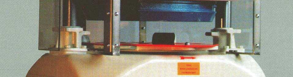
4 Safety Tips CAUTION: Do not reach inside the machine when it is in operation. While in operation, ALL the covers have to be in place for safety reasons. Before attempting any maintenance, repair work or cleaning, TURN OFF the main switch and disconnect the machine from the power supply (unplug from the receptacle). In case of electrical malfunction, NEVER by-pass the start button in such a way that you could operate the machine with one button only. The red plastic rounding plates shall be washed with lukewarm water, DO NOT clean them in pan washers or with hot water. When first installing the machine, please make sure that the machine is running in the right direction; the rounding plate has to turn counterclockwise. (check the arrow on top of the control panel) Notice: ATTENTION!!! Plates should have no gaps in pinhole and rear bracket. If the plates are over-sized please scrape off slightly in the rear block area. 4
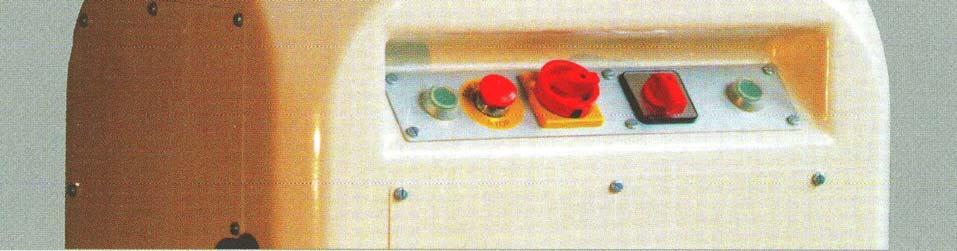
5 Manual 1. Setting-up and Installation of Machine After unpacking set the machine level and make sure it stands firm and does not wobble. Unscrew the rear cover plates and ask a qualified electrician to connect the machine to the power supply. Preselection The machine is switched ON and OFF by the Main Switch (211) in the middle of the control panel. The main Selector Switch (212A) has 3 positions indicating the following: A 214 Fig. 1 a) 1 - MANUAL The machine operates only as long as the Start Buttons (214) are depressed b) AUTO Normal operation i.e. press, divide, round c) 3 - REVERSE When machine jams it can be returned to its starting position by first turning pressure adjusting screw 22 (Fig. IV) counterclockwise and then depressing start buttons. If the machine fails to operate, first unplug it from the power supply, then remove the external covers at the bottom of the machine and turn the V-belt pulley counter-clockwise until it is free to move. Reconnect the machine to the power supply and restart the motor. Turn the pressure adjustment screw clockwise until it is back to its previous position. STOP = Emergency Stop Button: The machine stops when this button (213 Fig. I) is depressed. To restart the machine turn the emergency stop button counter- clockwise and depress jog buttons (214 Fig. I) DO NOT Reach inside the machine when the machine is running 2. Electrical Connection The machine is completely wired and ready for hook-up. The standard electrical 380 volts 3 phase and 50 cycles or 220 volts 3 phase and 60 cycles (USA), this is marked on the outside of the machine. When connecting the machine to the power supply make sure that the motor turns in the right direction. If the motor is properly connected, the rounding table rotates in the direction of the arrow (counterclockwise), during the rounding operation (see Fig. I above) 5
 above the motor compartment with approximately 7 quarts of SAE 46 (40 weight) engine oil, D keeping the oil level approximately 1 above the bottom of the gearbox.")

6 Fig. II Lubrication Fill the gearbox (Fig. II) above the motor compartment with approximately 7 quarts of SAE 46 (40 weight) engine oil, D keeping the oil level approximately 1 above the bottom of the gearbox. After several work cycles the pump should deliver enough oil to the upper gearbox chamber to allow for the lubrication of all the bearings in the gearbox chamber. Check carefully to ensure that this happens Fig. III S Cleaning of Machine Before First Use Remove both head covers from the machine. By turning to the left remove the dough entrapment ring (124 Fig. III) from the machine. Clean all grease from the rounding table (5 Fig. IV), head and dough entrapment ring (124 Fig. III). Fit the dough entrapment ring back into the machine. To do this proceed as follows: First insert a rounding plate into the machine, then place the dough entrapment ring on top of it and push the ring towards the center and rear until it hits against the stop lugs (123 Fig. III) While doing so, align smaller marking notch with its counterpart on the machine head. Set the switch to position 1 (Fig. I) and by pushing the START buttons slide the press piston carefully into the dough entrapment ring. When the two ring holders (115 Fig. III) reach the bottom position, release the push buttons and turn the dough entrapment ring to the right until it reaches the stop lug. 6

7 5. Rounding Plates (S-66 Fig. III) Prior to the initial operation all rounding plates supplied with the machine should be checked to make sure that they do not jam. Prior to the machine start up it is advisable to leave the machine for at least 8 hours in the production area, so the machine could adapt to the area s ambient temperature. The rounding table (No. 5 Fig. IV is protected against easy removal. This table should only be taken out by a service-technician, if there is a technical problem inside the machine. 6. Machine Operation Spread the appropriate amount of dough face down onto the rounding plate. (S- 66 Fig. III) Spread the dough to about ¾ of the outside of the plate and insert the plate into the machine. Make sure that the plate is properly inserted and that the back of the plate as well as the top of the rounding table are free of any dough pieces or any other material. To prevent the plate from being damaged by the knife blades. Set the working pressure very low, i.e. turn the pressure adjustment screw (22 Fig. IV) down from its upper limit. The setting of the pressure adjustment: set rounding handle No. 83 to number 0; then put the dough piece on the rounding plate and Z spread evenly. Go through the operating cycle then check whether the dough has spread all the way to the dough embracing ring. 2 Weigh individual dough pieces from the 26 center as well as from the outside of the plate to make sure they weigh the same. 3 If the outside pieces weigh less, you must turn the pressure adjustment screw 125 clockwise to the next number and repeat the test until all dough pieces weigh the same. If you make larger 130 dough pieces at a later time you may Fig. IV have to repeat this procedure. The rounding pressure is set by the weight adjustment screw (70 Fig. VII) in accordance with the weight of the individual dough piece. If they do not form into round dough balls, release the lock nut (71 Fig. VII) and turn the weight adjustment screw (70)clockwise or extend the rounding time by pushing in lever 83 (Fig. V). If the skin of the rounded dough pieces becomes coarse or forms a nipple in the middle, turn the weight adjustment screw (70 Fig. VII) counterclockwise or reduce the rounding time. The first batch of dough pieces is used for set-up purpose and for the final cleaning of the machine head as well as of the cutter blades, these dough pieces should be thrown away. 7
 to Zero, turn rounding plate upside down and place dough on it.")
8 7. Rounding Time Adjustment Push Rod (83 Fig. V) Setting Number or Rounding Revolutions NOTE: Adjust rounding push rod only when machine is idling 8. Dividing Without Rounding Turn weight adjustment screw 70 to its top position. Set the push rod (83 Fig. V) to Zero, turn rounding plate upside down and place dough on it. Slide the plate into the machine and start the machine. 9. Cutter Head Cleaning Prior to cleaning set Main Switch to O. Remove head covers and turn weight adjustment screw 70 to its top position. Remove the dough entrapment ring (124 Fig. III) from the machine and loosen both hand-wheels (68 Fig. VII) on each side of the machine head, thus allowing for the head to be tilted to the back. Apply flat iron lever 177, supplied with the machine, to both pins (4 Fig. VI) and push the knife blades out of the piston. After cleaning push the blades back into the piston by again using the flat lever. Next, tilt the head back into working position and secure it tightly by the two handwheels. After proper cleaning replace the dough entrapment ring, set the weight adjustment screw 70 to the required height of the rounding area and secure it by locknut Regular Cleaning The dough entrapment ring (124 Fig. III) has to be cleaned daily. It is also recommended to grease the ring slightly after each cleaning. All dough deposits have to be cleaned from the grooves (D Fig. III) on the outside of the head and from the dough entrapment ring, along which the dough entrapment ring moves p and down. The machine must not be washed or hosed down with water this would cause the machine to rust and the machine eventually would seize up. The removal and mounting of the dough entrapment ring is described in item 4. 8

. II.")
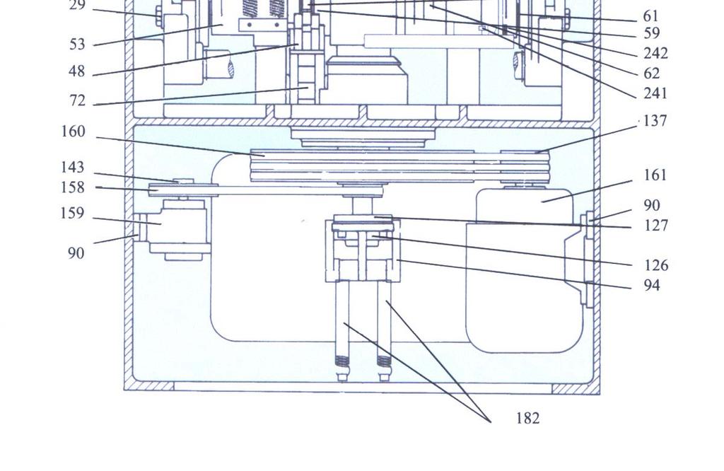
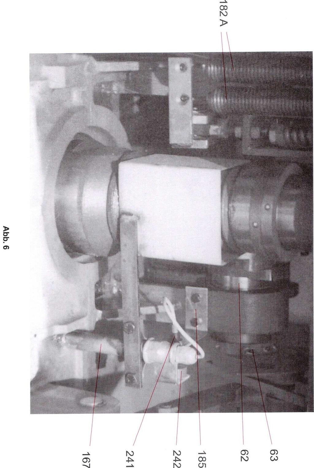
9 11. Manual Lubrication All 5 grease nipples should be filled up at least once every 3 months, with surplus grease being wiped clean. Fig. IX 182 a 12. Problems I. If the sequence of operations is not right; The machine may have been plugged into a socket which changed its polarity. Check for such a mistake. II. In case of electrical failures, only a qualified electrician should be called in to check the machines. III. If slipping, the V-belts may be tensioned by adjusting the position of the motor. I. Troubleshooting I. Dough pieces do not have a smooth surface after rounding. Remove upper side base covers and check whether any of the two springs are broken (Part No. 181 See Fig. VIII). II. Machine divides unevenly (cutting knives protrude). Remove the upper rear base cover and check if any of the two springs (No. 182 a) are broken. (See Fig. IX part No. 182 a). III. Machine does not stop and keeps on rounding. Remove the lower rear base cover and check whether any of the two springs (No. 182) are broken. IV. Machine keeps on recycling and does not stop in the up position. DANGER: Do not touch the machine and simply push the emergency stop button: then disconnect machine cable from power source. Call an electrician to have the machine checked out. 9
 (see Fig. I). Reconnect the machine and start the machine by pushing the two start buttons.")
10 V. Machine jams Stop the machine by pushing the emergency stop button. Loosen spindles No. 22 and 70 (see Fig. IV) until they hit the end stop. Put selector switch No. 212A to position 3 (reverse) (see Fig. I). Reconnect the machine and start the machine by pushing the two start buttons. The machine should now go back to its original up position at which time you must stop the machine. You now must turn the selector switch to the standard operating position No. 2. If the motor did not start, disconnect the machine from the power supply again. Remove the lower rear base cover and turn the large V-belt pulley by hand in a clockwise Fig. I motion until the machine is in the A 214 up position. VI. Machine stops during the dividing or rounding process. The V-belts of the drive motor are not tight enough. Remove the lower base cover on the left side of the machine. Loosen the mounting bolts of the motor. Tighten the V-belts by moving the motor towards the front of the machine, then re-tighten motor mounting bolts. 10
11 A Housing A Arch A Knife Support A Ring Support A Pressure Plate A Sliding Piece A Flange Bearing A Bearing A Spring A Shaft A Roller A Bushing A C Bushing Cpl. A Pin A Roll Pin A Worm Gear A Spacer A Lock Nut A Oil Shield A V-Belt Sheave A Ring A Bushing A Pressure Spindle A Bearing Block A Flange A Guide Pin A66-026L Bracket Left A66-026R Bracket Right A Push Rod A Arm A66-029L Screw Left A66-029R Screw Right A Bolt A Bushing House A Snap Ring A Swivel Arm A66-036L Connection Rod Left A66-036R Connection Rod Right A Column A Column Housing A Screw A Pin F. Knife Support A66-041L Screw Left A66-041R Screw Right A Fork A Connection Rod A Shaft A Knife Locking A66-046L Arch Left A66-046R Arch Right A Fork A Bolt A Roller A Pick-up Lever A Main Shaft A66-053L Rock Arm Left A66-053R Rock Arm Right A Roller A Screw A Cutting Arm A Guide Bar A Rounding Cam A Pilot Disk A Bull Gear A Bushing Spare Part List A Pin A Pin A Knurled Lock Nut A Bearing Housing A Adjustment Screw A Lock Nut A Shaft A Washer A Shaft A Shaft with Retain Ring A Shaft A Switch Arm A Switch Rod A Knob for Push Rod A Push Rod A Set Screw A Latch A Pin F. Lever Rounder A Motor Support A66-090A Pump Support A Lever Rounder A Pin F. Bearing Housing A Pin F. Bearing Housing A Arm A Push Lever A Roller A Pin F. Bush Lever A Pin A Push Rod A Push Rod A Ex. Housing Cpl. A Spring Bracket A Hook Screw Type A Piston Knife Head Assy & Flange A Moulding Ring Type A Screw A Bearing Housing A Cover A Swivel Bear A Seal A Pulley F. Motor A Spring Bracket A V-Belt Pulley A Cover Front A Cover Rear A66-157L Pressure Arm Left A66-157R Pressure Arm Right A V-Belt A V-Belt Set A Motor A Cleaning Brush A Cable Guide A Screw A Screw A Bracket A Lever to Engage Knives A Spring F. Pressure Regulator A Spring F. Knives A Spring F. rounding Chamber A Spring A66-182A Spring F. Cutting Arm A Bracket F. Sensor A Safety Guard 11
12 Please Find Electrical Parts at the End of this Manual with the Diagram Type Divisions Dough Portions (ounces) Plate No. Fully 4/40 A #45 #45 5/18 A #50 #50 6/150 A #415 #415 7/70 A #420 #420 8/250 A #47 #47 9/20 A #326 #326 10/25 A #336 #336 11/30 A #46 #46 Plate No. Semi/Easy Q Q1 30Q1 Q Q1 15Q1 Q Q1 10Q1 Q1 Cut Q1S Q1S Q Q2 30Q2 Q Q2 15Q2 Q Q2 10Q2 Q2 Cut Q2S Q2S Q Q3 36Q3 Q Q3A 18Q3 Q Q3A 12Q3 Q Q3 Q Q3 6Q3 Q Q3 Q3 Cut Q3S Q3S RH Set up RH RH Set up RH-EASY 12
13 Specifications for Different Types of Fully Automatic Machines A66-003A Knife Support Type 11/30A A66-003B Knife Support Type 10/25A A66-003C Knife Support Type 9/20A A66-004A Ring Support Type 10/25A + 11/30A A66-004B Ring Support Type 9/20A S-66/1 Moulding Plate Type 10/25A #336 S-66/2 Moulding Plate Type 11/30A #46 S-66/4 Moulding Plate Type 4/40A #45 S-66/5 Moulding Plate Type 5/18A 50 Parts S-66/6 Moulding Plate Type 6/150A 15 Parts S-66/7 Moulding Plate Type 7/70A 20 Parts S-66/8 Moulding Plate Type 9/20A #326 A66-115A Hook Screw Type 11/30A A66-115C Hook Screw Type 9/20A + 10/25A A66-116A Piston w/ Knife Head Assy Type 11/30A A66-116B Piston w/ Knife Head Assy Type 10/25A A66-116C Piston w/ Knife Head Assy Type 9/20A A66-116D Piston w/ Knife Head Assy Type 7/70A A66-116E Piston w/ Knife Head Assy Type 6/150A A66-116F Piston w/ Knife Head Assy Type 5/18A A66-116G Piston w/ Knife Head Assy Type 4/40A A66-124A Moulding Ring Type 11/30A A66-124B Moulding Ring Type 10/25A A66-124C Moulding Ring Type 9/20A A66-124D Moulding Ring Type 5/18A A66-161A Single Phase Motor 1,1 kw A Box CI-G UL A66-207B Timing RelayE57, 0x12F UL A66-211B On-Off Front Plate Please check you Machine Type Label before Ordering!!! 13
14 After unscrewing part no. 125a four times the knife can be taken out when head is turned. For mounting, line up the red markings on the piston knife 14
15 15
16 16
17 17
18 18
19 19
20 20
21 Page 3 of 3 21 ELA - 29
22 Automat Wiring Diagram Diagram No A Box A Panel (Standard) X1 A Clam (1-4) Q1 A Main Switch K1m A Contactor F1 A Relay F2 A66-207C Timing Relay S3 A Stop Button S4 A Sensor S1 A Start Button S2 A Start Button S5 A Selector Switch F3 A Protection Switch A Magnet A Box F4/F6 A Fuse Clamp A Fuse Holder A Fuse A Conductor Clamp F5 A66-240A Prot. Switch S6 A66-241A Sensor A66-242A Magnet 22
23 23
IMPORTANT SAFETY INSTRUCTIONS
 CONTENTS 1.SPECIFICATIONS... 1 2.INSTALLATION... 1 3.INSTALLATION OF THE SYNCHRONIZER... 2 4.ASSEMBLY OF HAND WHEEL... 2 5.INSTALLATION OF HAND WHEEL... 2 6.INSTALLING THE BELT COVER... 3 7.ADJUSTING THE
Industrial Sewing Machine TECHNICAL MANUAL SEWING MACHINE HEAD. Electronic Pattern Sewing Machine. Model PLK-G1010 A180E593P03
 Industrial Sewing Machine TECHNICAL MANUAL SEWING MACHINE HEAD Electronic Pattern Sewing Machine Model PLK-G1010 A180E593P03 FOR SAFE USE Before the installation, operation, and inspection for this product,
ENGINEER S MANUAL No.01
 1-NEEDLE, UNISON FEED, LOCKSTITCH MACHINE (AUTOMATIC LUBRICATION) LU-1510 1-NEEDLE, UNISON FEED, LOCKSTITCH MACHINE WITH AUTOMATIC THREAD TRIMMER (AUTOMATIC LUBRICATION) LU-1510-7 1-NEEDLE, UNISON FEED,
Industrial Sewing Machine TECHNICAL MANUAL SEWING MACHINE HEAD. Electronic Pattern Sewing Machine. Model PLK-G2516 A180E621P01
 Industrial Sewing Machine TECHNICAL MANUAL SEWING MACHINE HEAD Electronic Pattern Sewing Machine Model PLK-G2516 A180E621P01 FOR SAFE USE Before the installation, operation, and inspection for this product,
Altra Series Dampener
 Crestline TM Altra Series Dampener Installation Instructions Heidelberg MO X88-66 10/97 Rev-A GENERAL INFORMATION ATTENTION CRESTLINE ALTRA SERIES TM DAMPENER OWNER! Accel Graphic Systems provides parts
MAINTENANCE MANUAL TAIYO SEIKI CO., LTD.
 MAINTENANCE MANUAL TAIYO SEIKI CO., LTD. Introduction This Maintenance Manual explains how to replace and adjust the major components of the Automatic Taping Machine when required in daily operation.
INDEX I.- FINAL TEST FOR PRODUCT SAFETY 3 II.- REPLACEMENT PROCEDURES 3 III.- TROUBLE SHOOTING CHART 5 IV.- WIRING DIAGRAM 6 V.- ELECTRICAL RATING 6
 INDEX I.- FINAL TEST FOR PRODUCT SAFETY 3 II.- REPLACEMENT PROCEDURES 3 III.- TROUBLE SHOOTING CHART 5 IV.- WIRING DIAGRAM 6 V.- ELECTRICAL RATING 6 VI.- EXTERNAL PARTS FOR UPRIGHT VACUUM CLEANER PARTS
I N ST R UC T I ON. MODEL HAB500 AroMatic TM BREAD SLICERS MODEL FORM (4-99) AROMATIC BREAD SLICER 701 S. RIDGE AVENUE TROY, OHIO
 AROMATIC BREAD SLICER 701 S. RIDGE AVENUE TROY, OHIO") I N ST R UC AROMATIC BREAD SLICER T I ON S MODEL HAB500 AroMatic TM BREAD SLICERS MODEL HAB500 ML-104845 701 S. RIDGE AVENUE TROY, OHIO 45374-0001 FORM 34198 (4-99) TABLE OF CONTENTS GENERAL..........................................................
I N ST R UC AROMATIC BREAD SLICER T I ON S MODEL HAB500 AroMatic TM BREAD SLICERS MODEL HAB500 ML-104845 701 S. RIDGE AVENUE TROY, OHIO 45374-0001 FORM 34198 (4-99) TABLE OF CONTENTS GENERAL..........................................................
Hakki Pilke Raven spare parts manual
 1 ENGLISH Hakki Pilke Raven spare parts manual Valimotie 1, FI-85800 Haapajärvi, FINLAND Tel. +358 8 772 7300, Fax +358 8 772 732 info@maaselankone.fi, www.maaselankone.fi 2 Table of contents 1 Upper section
Industrial Sewing Machine TECHICAL MANUAL SEWING MACHINE HEAD. Electronic Pattern Sewing Machine. Model PLK-G1010 A180E593P02
 Industrial Sewing Machine TECHICAL MANUAL SEWING MACHINE HEAD Electronic Pattern Sewing Machine Model PLK-G1010 A180E593P02 FOR SAFE USE Before the installation, operation, and inspection for this product,
C-IV 60 CEILING FAN READ AND SAVE THESE INSTRUCTIONS. FAN RATING AC 120V. 60Hz
 C-IV 60 CEILING FAN READ AND SAVE THESE INSTRUCTIONS FAN RATING AC 120V. 60Hz Please do not use any electric or battery powered tools in the assembly and installation of this or any Matthews Fan Company
Model PLK-G5050 PLK-G10050
 Industrial Sewing Machine TECHNICAL MANUAL SEWING MACHINE HEAD Electronic Pattern Sewing Machine Model PLK-G5050 PLK-G10050 A180E686P01 FOR SAFE USE Before the installation, operation, and inspection for
Parts and Service Manual
 Section II Parts and Service Manual (70241A) CLARKE TECHNOLOGY Operator's Manual - MINI MAX Page -29- Frame and Front Cover Assembly Drawing 2/01 Page -30- CLARKE TECHNOLOGY Operator's Manual -MINI MAX
52 CEILING FAN READ AND SAVE THESE INSTRUCTIONS FAN RATING AC 120V.
 Irene 52 CEILING FAN READ AND SAVE THESE INSTRUCTIONS FAN RATING AC 120V. 60Hz TABLE OF CONTENTS Tools and Materials Required... 1 Package Contents... 1 Safety Rules... 2 Mounting Options... 3 Hanging
Service Documentation Market Release 7/84. Braun Kitchen machine KM 32 B 4209 with lamp
 Market Release 7/84 Braun Kitchen machine KM 32 B 4209 with lamp 4209 Exploded Drawing BAG Rev: 7/84 4209 4209-2 Service Information BAG Rev: 12/88 4209 Pos. No. Part Description Part Number 1 Male drive
User s Manual and Operating Instructions
 User s Manual and Operating Instructions Model Numbers: PT-18W-DDF-A, PT-20F-DDF-A, PT-20S-DDF, PT-24O-DDF, PT-24-DDF, PT-24-DDF-F, PT-30-DDF, PT-30P-DDF-A, PT-30P-DDF-AF READ AND SAVE THESE INSTRUCTIONS
Please read this manual before using the machine. Please keep this manual within easy reach for quick reference.
 INSTRUCTION MANUAL Please read this manual before using the machine. Please keep this manual within easy reach for quick reference. HIGH SPEED SINGLE NEEDLE STRAIGHT LOCK STITCHER Thank you very much for
ILLUSTRATIONS ARE FOR REFERENCE ONLY AND ARE SUBJECT TO CHANGE WITHOUT NOTICE ITEM P/N DESCRIPTION
 TC-0 TURN PLATE TC-0 TURN PLATE 0 0 0 TC-0-000 TURNTABLE TC-0-00 TURNTABLE, TC-0 TC-0-00 SCREW, M X TC-0-00 COVER, TC-0 TC-0-00 RETAINING PIN TC-0-00 CLAMP TC-0-00 CLAMP SEAT TC-0-0 CLAMP SEAT, TC-0 TC-0-00
Food Waste Disposer Instruction Manual
 Food Waste Disposer Instruction Manual See insert for specific information about your new disposer NOTE: IMPORTANT: CAUTION: This Food Waste Disposer has been designed to operate on 110-120 Volt, 60 Hz
SERVICE MANUAL VC3ED FULL SIZE ELECTRIC CONVECTION OVEN - NOTICE -
 SERVICE MANUAL VC3ED FULL SIZE ELECTRIC CONVECTION OVEN VC3ED ML-137013 - NOTICE - This Manual is prepared for the use of trained Vulcan Service Technicians and should not be used by those not properly
READ AND SAVE THESE INSTRUCTIONS
 READ AND SAVE THESE INSTRUCTIONS CEILING FAN INSTALLATION AND OPERATION INSTRUCTION FAN RATING AC 120V. 60Hz UL LISTED MODEL: AC-552OD WEIGHT OF FAN: 6.82 KGS 1. TOOLS AND MATERIALS REQUIRED Philips screw
monty 4200 Truck Tire Changer Spare Parts list
 monty 4200 Truck Tire Changer Spare Parts list Date 08/12/09 Figure 1 Baseframe Date 08/12/09 Page 2 Monty 4200 Spare Parts list Figure 2A Carriage with Mounting Arm Date 08/12/09 Page 3 Monty 4200 Spare
TCUT10UL 2.5 HP 10 Tile Saw Assembly & Operating Instructions
 TCUT10UL 2.5 HP 10 Tile Saw Assembly & Operating Instructions READ ALL INSTRUCTIONS AND WARNINGS BEFORE USING THIS PRODUCT. This manual provides important information on proper operation and maintenance.
30-YEAR LIMITED WARRANTY
 PROGRESS LIGHTING 30-YEAR LIMITED WARRANTY PROGRESS LIGHTING FAN MOTORS ARE WARRANTED TO THE END USER TO BE FREE OF ELECTRICAL AND/OR MECHANICAL DEFECTS FOR A PERIOD OF 30 (THIRTY) YEARS FROM DATE OF SALE.
Los Angeles Abrasion Machine HM-70A & HM-70AF
 Operating Manual Los Angeles Abrasion Machine HM-70A & HM-70AF Rev: 07/24/2018 PHONE: 800-444-1508 740-548-7298 P.O. Box 200, Lewis Center, Ohio 43035-0200 E-mail: customerservice@gilsonco.com Website:
Model No: 56DFH-L HS-1289-C. Cover for non-light option
 Owner s Manual Starfire Model No: 56DFH-L HS-1289-C Cover for non-light option These instructions contain 5 pages: Page 1: Foreword Page 2: Unpack and inspect parts contained, and pre-installation notes
TOOLS AND MATERIALS REQUIRED
 5 YEAR LIMITED WARRANTY Thank you for purchasing our product. It is our policy to furnish you with high quality products at a fair price. With proper installation your fan should provide you with years
Crestline Dampening System
 Crestline Dampening System Installation Instructions Hamada 500, 600, 700, E-47, SU47 Series Parent Press X88-25 01/2001 Rev-C 2593 GENERAL INFORMATION ATTENTION CRESTLINE DAMPENER OWNER! Accel Graphic
Part 2: Installation Instructions cl
 Contents Page: Part 2: Installation Instructions cl. 381-382 1. Delivery scope............................... 3 2. General and Transportation safety precautions........... 3 3. Stand installation 3.1 Installing
Part 3: Service manual, class
 Contents Page: Part : Service manual, class 7-75. General.................................................. Gauges................................................. 4. Description and adjustment of the
EAGLE 2000B EAGLE 2000BE EAGLE 2000EBT MUST READ MANUAL PRIOR TO INSTALLING MACHINE
 EAGLE 2000B EAGLE 2000BE EAGLE 2000EBT MUST READ MANUAL PRIOR TO INSTALLING MACHINE Contents 1 Machine Safety Information 3 1.5 Safety Precautions Prior to Operating Machine 6 2 Machine Installation 7
User s Manual and Operating Instructions
 User s Manual and Operating Instructions Model Numbers: CL-30P-DDF, CL-20F-DDF, CL-24O-DDF, CL-30-DDF READ AND SAVE THESE INSTRUCTIONS IMPORTANT: Read and understand all of the directions in this manual
Operation and Safety Manual ABSPMS-80L and ABSPMS-80/60L
 Operation and Safety Manual ABSPMS-80L and ABSPMS-80/60L Serial Number: Model: ABSPMS-80L American Baking Systems 290 Legion Court S.W. Cedar Rapids, IA 52404 www.abs1.net OPERATION MANUAL AND PARTS LIST
CEILING FAN OWNER'S MANUAL
 CEILING FAN OWNER'S MANUAL READ AND SAVE THESE INSTRUCTIONS MODEL: 52-135-5WA-13 FAN RATING AC 120V. 60Hz CUL LISTED MODEL : AC-552OD 1. TOOLS AND MATERIALS REQUIRED Philips screw driver Blade screw driver
OPERATING & SERVICE PARTS MANUAL HDS-215 COMBINATION SHRINK SYSTEM
 OPERATING & SERVICE PARTS MANUAL HDS-215 COMBINATION SHRINK SYSTEM FOR HOT KNIFE AND IMPULSE MACHINES READ ALL INSTRUCTIONS CAREFULLY BEFORE OPERATING EQUIPMENT TABLE OF CONTENTS Electrical Requirements
CEILING FAN OWNER'S MANUAL
 CEILING FAN OWNER'S MANUAL MODEL: Pelham HVFC# 2299 Old Bronze Satin Nickel Polished Nickel READ AND SAVE THESE INSTRUCTIONS FAN RATING AC 120V. 60Hz. CUL LISTED MODEL: AC-554SY05-7S WEIGHT OF THE FAN:
1. SAFETY RULES WARNING WARNING. 8. Avoid placing objects in the path of the blades.
 1 1. SAFETY RULES 1. To reduce the risk of electric shock, insure electricity has been turned off at the circuit breaker or fuse box before beginning. 2. All wiring must be in accordance with the National
ORIGINAL SPARE PARTS CHD-6330
 ORIGINAL SPARE PARTS CHD-6330 85010075/02 Revision 02/2013 FRAME 1.0 FRAME 1.0 Rif Code Description 1 *4399880 SCREW TE 10x40 2 *4399378 WASHER D.10 (10,5x21x2) 3 *6611330 SUPPORT 4 *7910913 CHUCK 5 *4399288
TACH-IT MODEL #3568 SEMI-AUTOMATIC TWIST TIE MACHINE OPERATION MANUAL AND PARTS LIST
 TACH-IT MODEL #3568 SEMI-AUTOMATIC TWIST TIE MACHINE OPERATION MANUAL AND PARTS LIST 1 TABLE OF CONTENTS: SECTION 1 CAUTION PAGE 3 SECTION 2 PARTS IDENTIFICATION PAGE 4 SECTION 3 MACHINE DIMENSIONS AND
CUTMASTER Strip Cutting Machine
 EASTMAN THE EASTMAN CUTMASTER Strip Cutting Machine WARNING Safety glasses must be worn at all times when operating or servicing this equipment. Instruction Manual & Illustrated Parts List Please read
Orrin. Instruction Manual. Includes our new CoolTouch TM Control System Looks permanent, but goes wherever you go! U.S.
 Includes our new CoolTouch TM Control System Looks permanent, but goes wherever you go! U.S. Patent Pending Orrin A Kichler Select ceiling fan Kichler Lighting 7711 East Pleasant Valley Road P.O. Box 318010
3SA60 3SA60+LED. Vogue & Vogue Plus. Net weight. This instruction contains 11 pages:
 Vogue & Vogue Plus 3SA60 3SA60+LED This instruction contains 11 pages: Page 1: Foreword Page 2~3: Unpack and inspect parts contained Page 4~5: Notes before installation and Hanging system installation
MODEL 625-DR & 625-S
 Grand Rapids, Michigan, U.S.A. 49504-5298 USER S OPERATING AND INSTRUCTION MANUAL MODEL 625-DR & 625-S DOUGH DIVIDER / ROUNDERS 0625S20000-CVR MODEL 625 DOUGH DIVIDER - ROUNDERS INDEX DEFINITIONS.. GEN93118
Lifetime Limited Warranty
 Hampton Bay Lifetime Limited Warranty The retailer warrants the fan motor to be free from defects in workmanship and material present at time of shipment from the factory for a lifetime after the date
GL190-A / GL191-A / GJ461-A
 Planetary Mixer Instruction manual Model: GL190-A / GL191-A / GJ461-A GL190-A_GL191_A_GJ461-A_A5_v3_170809.indb 1 2017/8/9 17:39 Exploded diagram and spare parts list GL190-A GL190-A_GL191_A_GJ461-A_A5_v3_170809.indb
Exploded View - Model J-7020M/J-7040M Miter Cut-off Saw Base
 22 Exploded View - Model J-7020M/J-7040M Miter Cut-off Saw Base Parts List - Model J-7020M/J-7040M Miter Cut-off Saw Base 1 J-5507591 Base, Machine 1 1-1 5512197 Plug, Drain (3/8in, PT) 2 5507592 Screw,
CEILING FAN OWNER'S MANUAL
 Distinctive Lighting and Ceiling Fans CEILING FAN OWNER'S MANUAL MODEL: 52CW2L5-GM 52CW2L5-OBB READ AND SAVE THESE INSTRUCTIONS FOR CEILING FAN PARTS AND SERVICE, CALL 1-877-902-5588 FAN RATING AC 120V.
CEILING FAN OWNER'S MANUAL
 CEILING FAN OWNER'S MANUAL READ AND SAVE THESE INSTRUCTIONS MODEL: 52-771-5TK-13 52-771-5BW-SN 52-771-5WH-WH FAN RATING AC 120V. 60Hz CUL LISTED MODEL : AC-552A 1. TOOLS AND MATERIALS REQUIRED Philips
CBT LW MAINTENANCE GUIDE
 CBT LW MAINTENANCE GUIDE PICTOGRAMS Each Signifier displayed here is specific to this User Manual. Menu Previous Advance Note Tip Example Powder Feeder Mixing Bowl Weigh Scale CBP Tanks Control Panel PSD
42 Kevlar. Instruction Manual. Kichler Lighting 7711 East Pleasant Valley Road P.O. Box Cleveland, Ohio
 42 Kevlar Kichler Lighting 7711 East Pleasant Valley Road P.O. Box 318010 Cleveland, Ohio 44131-8010 Customer Service 866.558.5706 8:30 AM to 5:00 PM EST, Monday - Friday Instruction Manual 1 1. SAFETY
60" Tulle PatioTM. Instruction Manual. A Kichler Select ceiling fan
 60" Tulle PatioTM A Kichler Select ceiling fan cul Certified for Wet Location Kichler Lighting 7711 East Pleasant Valley Road P.O. Box 318010 Cleveland, Ohio 44131-8010 Customer Service 866.558.5706 8:30
OWNER S MANUAL ABSFBM-200T
 OWNER S MANUAL ABSFBM-200T American Baking Systems, Inc 290 Legion Court S.W. Cedar Rapids, IA 52404 Phone: 319-373-5006 Fax: 319-373-5008 CONTENTS Introduction (2) Installation & Commissioning (3) Operation
Glendale 52 in Ceiling Fan Owner's Manual. Glendale Ventilador de Techo de 1.32 m Manual del Propietario
 Glendale 52 in Ceiling Fan Owner's Manual Glendale Ventilador de Techo de 1.32 m Manual del Propietario Hampton Bay Lifetime Motor Warranty The retailer warrants the fan motor to be free from defects in
Nilfisk Inc Winnetka Avenue North Minneapolis, MN REV.03( ) VF80189
 VF80189") Nilfisk Inc. 9435 Winnetka Avenue North Minneapolis, MN 55445 www.usviper.com REV.03(05-) VF8089 SAFETY PRECAUTIONS This machine is intended for commercial use. It is constructed for use in an indoor
Nilfisk Inc. 9435 Winnetka Avenue North Minneapolis, MN 55445 www.usviper.com REV.03(05-) VF8089 SAFETY PRECAUTIONS This machine is intended for commercial use. It is constructed for use in an indoor
Please read this manual before using the machine. Please keep this manual within easy reach for quick reference.
 DA-927A DA-928A INSTRUCTION MANUAL Please read this manual before using the machine. Please keep this manual within easy reach for quick reference. TWIN NEEDLE / THREE NEEDLE FEED OFF THE ARM DOUBLE CHAIN
BRD 36 Part Bun and Roll Divider Rounder Model BRD-36-3, 36 part ¾ - 3 oz Model BRD-36-4, 36 part 1 ½ - 4 oz
 BRD 36 Part Bun and Roll Divider Rounder Model BRD-36-3, 36 part ¾ - 3 oz Model BRD-36-4, 36 part 1 ½ - 4 oz Installation and Operations Manual Rev 001 07/08 Model BRD-36-3 Shown Table of Contents Page
Scrubber User Manual
 Scrubber User Manual AS430C VIPER NORTH AMERICA [866] 418-4737 [866] 41-VIPER VF90031-US Rev.01 TABLE OF CONTENTS USER MANUAL INTRODUCTION... 2 CONTENTS............................. 2 PURPOSE.............................
CEILING FAN OWNER'S MANUAL
 Style that revolves around you. CEILING FAN OWNER'S MANUAL Hover with DC motor 12/14 WARNING: Read and follow these instructions carefully and be mindful of all warnings shown throughout. GENERAL INSTALLATION
M5 BLUE BOY FIVE GALLON PAINT MIXER Owner s Manual
 M5 BLUE BOY FIVE GALLON PAINT MIXER Owner s Manual Introduction..3 Safety Precautions 4 Installation Instructions 5 Electrical Connections..7 Operating Instructions..8 Maintenance Procedures...8 Parts
ASTRO ENVELOPE FEEDER AMC FOR HEIDELBERG PRINTMASTER INSTALLATION AND OPERATING INSTRUCTIONS
 ASTRO ENVELOPE FEEDER AMC-2000-17 FOR HEIDELBERG PRINTMASTER INSTALLATION AND OPERATING INSTRUCTIONS INTRODUCTION Thank you for purchasing the Astro Envelope Feeder. It is fast, efficient, reliable, and
52 StarkkTM. Instruction Manual. A Kichler Select ceiling fan
 52 StarkkTM A Kichler Select ceiling fan Kichler Lighting 7711 East Pleasant Valley Road P.O. Box 318010 Cleveland, Ohio 44131-8010 Customer Service 866.558.5706 8:30 AM to 5:00 PM EST, Monday - Friday
CEILING FAN OWNER'S MANUAL
 Style that revolves around you. CEILING FAN OWNER'S MANUAL Vail with DC motor 10/15 WARNING: Read and follow these instructions carefully and be mindful of all warnings shown throughout. GENERAL INSTALLATION
OPERATING MANUAL. Los Angeles Abrasion Machine. PHONE: FAX: Website:
 OPERATING MANUAL Los Angeles Abrasion Machine Rev: 07/19/2012 PHONE: 800-940-1928 FAX: 800-863-1573 E-mail: service@certifiedmtp.com Website: www.certifiedmtp.com SAFETY INSTRUCTIONS Whether you are the
installation and operation manual for Hunter Ceiling Fans
 For Your Records and Warranty Assistance Model Name: Catalog/Model No.: Serial No.: Date Purchased: Where Purchased: For reference also attach your receipt or a copy of your receipt to the manual. installation
60" Hatteras BayTM. Patio. Instruction Manual. Includes our new Wall Control System. A Kichler Décor ceiling fan
 Includes our new Wall Control System 60" Hatteras BayTM Patio A Kichler Décor ceiling fan Kichler Lighting 7711 East Pleasant Valley Road P.O. Box 318010 Cleveland, Ohio 44131-8010 Customer Service 866.558.5706
ÉQUIPEMENT DOYON INC. 1255, rue Principale Linière, Qc, Canada G0M 1J0
 ÉQUIPEMENT DOYON INC. 1255, rue Principale Linière, Qc, Canada G0M 1J0 Tel.: 1 (418) 685-3431 Canada: 1 (800) 463-1636 US: 1 (800) 463-4273 FAX: 1 (418) 685-3948 Internet: http://www.doyon.qc.ca e-mail:
Installation and Operation Manual For Hunter Ceiling Fans /16/2004
 Installation and Operation Manual For Hunter Ceiling Fans 1 2 CONGRATULATIONS! Your new Hunter ceiling fan is an addition to your home or office that will provide comfort and performance for many years.
2 Installation Instructions For Vari-Fan Ceiling Fans Installation Instructions For Vari-Fan Ceiling Fans 11
 Installation Instructions For Installation Instructions For Vari-Fan Ceiling Fans Vari-Fan Ceiling Fans Installation Instructions For Vari-Fan Ceiling Fans Vari-Fan Ceiling Fans DC powered fans designed
Lifetime Limited Warranty
 Hampton Bay Lifetime Limited Warranty The retailer warrants the fan motor to be free from defects in workmanship and material present at time of shipment from the factory for a lifetime after the date
7165 Dust Collector Owner s Manual
 7165 Dust Collector Owner s Manual Oliver Machinery M-7165 12/2016 Seattle, WA Copyright 2003-2017 info@olivermachinery.net www.olivermachinery.net CONTENTS IMPORTANT SAFETY RULES----------------------------------------------------------------
PARTS MANUAL. American Dish Service ADS CONVEYOR DISHWASHER MODELS: ADC-44 L-R/R-L EFFECTIVE: SEPTEMBER 1, 2001
 EFFECTIVE: SEPTEMBER 1, 2001 ADS CONVEYOR DISHWASHER MODELS: ADC-44 L-R/R-L PARTS MANUAL 900 Blake Street Edwardsville, Kansas 66111 (913)422-3700 211-0044L-R / 212-0044R-L ADC-44 Conveyor Dishwasher 2
(3 plastic wire connectors,blade balancing kit, 2 extra mounting screws #10-32 for outlet box.)
") Excel Lighting & Manufacturing Ltd. Lifetime Limited Warranty Excel Lighting & Manufacturing Ltd. Warrants the fan motor to be free from defects in workmanship and material present at time of shipment
Excel Lighting & Manufacturing Ltd. Lifetime Limited Warranty Excel Lighting & Manufacturing Ltd. Warrants the fan motor to be free from defects in workmanship and material present at time of shipment
XPS-ProDry User s Guide Dryer Base
 XPS-ProDry User s Guide XPS-ProDry User s Guide Dryer Base For Use with Inkjet Imaging Systems Manual Part#: M-3120 Revision: August 2005 XPS-ProDry User s Guide Written by Frank Mauri & John Brand Published
TECHNICAL INFORMATION B 890 and B 990 Rotary Irons (US Models)
") TECHNICAL INFORMATION B 890 and B 990 Rotary Irons (US Models) 2011 Miele USA Table of Contents A B C D 010 Warning and Safety Instructions... 5 1 General... 5 2 Touch Current Measurement... 6 3 Risk of
TECHNICAL INFORMATION B 890 and B 990 Rotary Irons (US Models) 2011 Miele USA Table of Contents A B C D 010 Warning and Safety Instructions... 5 1 General... 5 2 Touch Current Measurement... 6 3 Risk of
FitchTM. Instruction Manual. Includes our Basic Function CoolTouch TM Control System Looks permanent, but goes wherever you go!
 Includes our Basic Function CoolTouch TM Control System Looks permanent, but goes wherever you go! FitchTM A Kichler Décor ceiling fan U.S. Patent Pending Kichler Lighting 7711 East Pleasant Valley Road
XC-18. NOTE: *Machine shown without Lift-Up Safety Guard. This guard is included with machine. Machine should not be operated without this guard.
 XC-18 NOTE: *Machine shown without Lift-Up Safety Guard. This guard is included with machine. Machine should not be operated without this guard. EXTREMA MACHINERY COMPANY, INC. PO BOX 1450, ALBANY, LOUISIANA
Lifetime Limited Warranty
 Hampton Bay Lifetime Limited Warranty The retailer warrants the fan motor to be free from defects in workmanship and material present at time of shipment from the factory for a lifetime after the date
ATTIAS MANUFACTURERS OF ATTIAS DOUGH MIXERS 265 BOWERY NEW YORK, N.Y TEL: (212) FAX: (212) COMMERCIAL DOUGH MIXERS
 FAX: (212) COMMERCIAL DOUGH MIXERS") ATTIAS MANUFACTURERS OF ATTIAS DOUGH MIXERS 265 BOWERY NEW YORK, N.Y. 10002 TEL: (212) 475-0145 FAX: (212) 979-1423 COMMERCIAL DOUGH MIXERS INSTALLATION AND OPERATING INSTRUCTION MANUAL MODEL# USA-60 MODEL#
ATTIAS MANUFACTURERS OF ATTIAS DOUGH MIXERS 265 BOWERY NEW YORK, N.Y. 10002 TEL: (212) 475-0145 FAX: (212) 979-1423 COMMERCIAL DOUGH MIXERS INSTALLATION AND OPERATING INSTRUCTION MANUAL MODEL# USA-60 MODEL#
COMMUTATOR GRINDING AND TURNING TOOLS - RIGHT ANGLE INSTRUCTIONS
 COMMUTATOR GRINDING AND TURNING TOOLS - RIGHT ANGLE INSTRUCTIONS CAUTION: All Grinder Supports MUST BE INSULATED from electrically live circuits and tested for absence of current at the Grinder, before
OTO BONDER OWNER S MANUAL WITH CIRCULATING SYSTEM MACHINERY DIVISION - - L to R Unit Shown
 GBAC RROTO OTO BONDER BONDER WITH CIRCULATING SYSTEM G B MACHINERY DIVISION OWNER S MANUAL L to R Unit Shown - - IMPORTANT FOREWORD 1) To ensure efficiency, the GBAC must be properly maintained. Carefully
SuperKlean Washdown Products
 DURAREEL DR8 & DR8S INSTALLATION AND MAINTENANCE INSTRUCTIONS **DO NOT THROW AWAY AFTER INSTALLATION** **SAVE AND DISPLAY PROMINENTLY WHERE THIS EQUIPMENT IS USED** GENERAL WARNINGS High pressure and hot
Select. Sutter PlaceTM. Instruction Manual. A Kichler Select ceiling fan
 Sutter PlaceTM A Kichler ceiling fan Kichler Lighting 7711 East Pleasant Valley Road P.O. Box 318010 Cleveland, Ohio 44131-8010 Customer Service 866.558.5706 8:30 AM to 5:00 PM EST, Monday - Friday Instruction
Section - A Vacuum Feed Attachment
 Tray Box Former 1.0 Section - A Vacuum Feed Attachment A-1 Table of Contents SECTION NO. PAGE SECTION NO. PAGE A.0 INTRODUCTION PURPOSE... A-3 A.1 SET-UP AND ADJUSTMENTS FIGURE A-1 VACUUM FEED MOUNTING
MNEFDD54 & MNBCDD54 GALVANIZED WALL FANS Installation, Operation, and Maintenance Instructions
 FARM PRODUCTS DIVISION MEMBER OF AMCA AMERICAN COOLAIR CORPORATION P.O. BOX 2300 JACKSONVILLE, FLORIDA 32203 PHONE (904) 389-3646 FAX (904) 387-3449 E-MAIL - fans@coolair.com MNEFDD54 & MNBCDD54 GALVANIZED
MEIKO Undercounter Dish and Glass Washing Machine. Spare Parts List 208V/230V 1/3-PHASE 60 HZ
 MEIKO Undercounter Dish and Glass Washing Machine Spare Parts List FV40.G 08V/0V /-PHASE 60 HZ Rev.. Updated: 0-8-04 CONTENTS. WASH PUMP PAGE. WASH SYSTEM PAGE. BOOSTER PUMP PAGE 7. SOLENOID / FILL VALVE
Tornado Operations & Maintenance Manual
 TORNADO INDUSTRIES 7401 W. LAWRENCE AVENUE CHICAGO, IL 60706 (708) 867-5100 FAX (708) 867-6968 www.tornadovac.com Tornado Operations & Maintenance Manual MODEL NO. 99690 BD 22/14, 99720 BD 26/14 L9722
DA-9270 TWIN NEEDLE (THREE NEEDLE) FEED OFF THE ARM DOUBLE CHAIN STITCHER. English
 FEED OFF THE ARM DOUBLE CHAIN STITCHER. English") TWIN NEEDLE (THREE NEEDLE) FEED OFF THE ARM DOUBLE CHAIN STITCHER English Thank you very much for buying a BROTHER sewing machine. Before using your new machine, please read the safety instructions below
TWIN NEEDLE (THREE NEEDLE) FEED OFF THE ARM DOUBLE CHAIN STITCHER English Thank you very much for buying a BROTHER sewing machine. Before using your new machine, please read the safety instructions below
INSTALLATION AND MAINTENANCE OF THE "THOMPSON-BRITISH" AUTOMATIC PLATEN
 INSTALLATION AND MAINTENANCE OF THE "THOMPSON-BRITISH" AUTOMATIC PLATEN Installation and Maintenance of The "Thompson-British" Auto Platen Lifting Bolt. Motor. Direction of rotation. Oiling. The machine
TLA-1245 EFFICIENT HEAT CYCLE SHRINK TUNNEL OPERATION MANUAL
 TLA-1245 EFFICIENT HEAT CYCLE SHRINK TUNNEL OPERATION MANUAL Contents 1. Introduction... 3 1.1 Features... 3 1.2 Specifications... 3 2. Installation... 3 3. Machine explosion drawing... 4 4. Equipment
LED. 60 StarkkTM. Instruction Manual. A Kichler Select ceiling fan
 60 StarkkTM LED A Kichler Select ceiling fan Kichler Lighting 7711 East Pleasant Valley Road P.O. Box 318010 Cleveland, Ohio 44131-8010 Customer Service 866.558.5706 8:30 AM to 5:00 PM EST, Monday - Friday
Lifetime Limited Warranty
 World Imports Lifetime Limited Warranty The retailer warrants the fan motor to be free from defects in workmanship and material present at time of shipment from the factory for a lifetime after the date
1. SAFETY RULES. 1. To reduce the risk of electric shock, insure electricity has been turned off at the circuit breaker or fuse box before beginning.
 Kichler Basics 403 1 1. SAFETY RULES 1. To reduce the risk of electric shock, insure electricity has been turned off at the circuit breaker or fuse box before beginning. 2. All wiring must be in accordance
INTELLI-VAC 14 INTELLI-VAC 18
 INTELLI-VAC 14 INTELLI-VAC 18 INTRODUCTION OPERATING & MAINTENANCE INSTRUCTIONS This operator s book has important information for the use and safe operation of this machine. Read this book carefully before
1500 RPM BURNISHER. Model P WARNING: OPERATOR MUST READ AND UNDERSTAND THIS MANUAL COMPLETELY BEFORE OPERATING THIS EQUIPMENT.
 OPERATOR S MANUAL & PARTS LIST 1500 RPM BURNISHER Model P1500-3 U.S. Patent Number 4,845,798 U.S. Patent Number 4,756,042 U.S. Patent Number 296,252 WARNING: OPERATOR MUST READ AND UNDERSTAND THIS MANUAL
PLC-1700 Series PLC-1710, , 1760, , 1760L
 Post-bed, Unison-feed, Lockstitch Machine PLC-1700 Series PLC-1710, 1710-7, 1760, 1760-7, 1760L ENGINEER S MANUAL 40040656 No.E372-00 Introduction This Engineer s Manual is for technical service engineers.
I N ST R UC T I ON MODEL 2612 & 2712 SLICERS MODELS 2612 ML ML FORM (12-98) 2612 SLICER
 2612 SLICER") I N ST R UC 2612 SLICER T I ON S MODEL 2612 & 2712 SLICERS MODELS 2612 ML-104829 2712 ML-104822 701 S. RIDGE AVENUE TROY, OHIO 45374-0001 FORM 34141 (12-98) Installation, Operation, and Care of MODEL 2612
I N ST R UC 2612 SLICER T I ON S MODEL 2612 & 2712 SLICERS MODELS 2612 ML-104829 2712 ML-104822 701 S. RIDGE AVENUE TROY, OHIO 45374-0001 FORM 34141 (12-98) Installation, Operation, and Care of MODEL 2612
CEILING FAN OWNER'S MANUAL
 CEILING FAN OWNER'S MANUAL READ AND SAVE THESE INSTRUCTIONS MODELS: 52-ECM-5RV-13 52-ECM-5RV- 52-ECM-5RV-SN FAN RATING AC 120V. 60Hz CUL LISTED MODEL : AC-552 1. TOOLS AND MATERIALS REQUIRED Philips screwdriver
Spare Parts List. Universal Utensil Washer FV V / 460V / 60HZ 3P / MIKE 2
 Spare Parts List Universal Utensil Washer FV 0. 0-0V / 60V / 60HZ P / MIKE Updated: --00 FV 0. Contents: 0.6 Wash Pump 0. Final Rinse System Lateral 0.6 Final Rinse System 0. Wash System 0. Solenoid Valve
An ibuy Stores Company
 REVISED STARTING SERIAL NO. 060604 PARTS MANUAL Model SK-4 4 DOWNCUT CONCRETE/ASPHALT WALK BEHIND SAWS SKU NO. MODEL POWER OPTION 45400D SK4-9H HONDA ENGINE 9 HP GX0 45600D SK4-H HONDA ENGINE HP GX40 4800D
FORMATIC Instruction Manual
 FORMATIC Instruction Manual Gibson Street, Leeds Road, Bradford West Yorkshire, England. BD3 9TR Telephone: +44 (0) 1274 668771 Fax: +44 (0) 1274 665214 FORMATIC CONTENTS 1. Introduction 2. Technical Specification