HEAT PUMP INSTALLATION MANUAL
|
|
|
- Vivien Hicks
- 5 years ago
- Views:
Transcription


1 DUCTLESS INVERTER HEAT PUMP INSTALLATION MANUAL Models: TERRA09HP230V1A TERRA12HP230V1A TERRA18HP230V1B TERRA24HP230V1B

2 Thank you for choosing a Gree Terra Ductless Heat Pump for your customer. Please read this installation manual carefully before installing and starting up the Terra System. Take a moment to fill out the product and installation form on the back cover. Retain both the manual and installation record for future reference. Contents Safety Precautions 2 System Requirements 4 Suggested Tools 5 Site Instructions 6 Dimensions 7 Indoor Unit 9 Outdoor Unit 12 Refrigerant Piping 13 Power and Wiring 16 Vacuum Testing 19 Start-up 21 Troubleshooting 22 1
3 SAFETY PRECAUTIONS Please read the following before installation. Recognize safety information. This is the safety-alert symbol. When you see this symbol on the unit and in instructions or manuals, be alert to the potential for personal injury. Understand these signal words: DANGER, WARNING, and CAUTION. These words are used with the safety-alert symbol. DANGER identifies the most serious hazards which will result in severe personal injury or death. WARNING signifies hazards which could result in personal injury or death. CAUTION is used to identify unsafe practices which may result in minor personal injury or product and property damage. NOTE is used to highlight suggestions which will result in enhanced installation, reliability, or operation. NOTE: Your actual heat pump system and related devices may differ from the images shown in this manual. This appliance is not intended for use by children without responsible adult supervision. Proper care should be taken to ensure safety. WARNING Heat pumps, air conditioners & heating equipment should be installed, started up, and serviced only by qualified installers and service technicians. Air conditioning, heat pumps and refrigeration systems are hazardous due to high voltage electrical components, high refrigerant pressures, and moving parts. 2
4 SAFETY PRECAUTIONS CAUTION The unit should be installed and serviced only by trained, qualified installers and service mechanics. Untrained personnel can perform basic maintenance functions such as cleaning coils. All other operations should be performed by trained service personnel. Owner should be cautioned that children should not play with the appliance. WARNING ELECTRICAL SHOCK HAZARD Failure to follow this warning could result in personal injury or death. Before installing, servicing or modifying the system, the main electrical disconnect switch must be in the OFF position. There may be more than one disconnect switch. Lock out and tag all switches with a warning label. General Safety Precautions A dedicated power supply circuit should be used in accordance with local electrical safety regulations and National Electrical Codes (NEC). Ensure that the entire system is reliably grounded. Use proper size circuit breaker to protect equipment against short circuit and overload conditions. Observe all local codes and regulations. INSTALLATION SITE INSTRUCTIONS Proper installation site is vital for correct and reliable operation of the system. Avoid the following installation locations : Strong heat sources, vapors, flammable gas or volatile liquids. High-frequency electro-magnetic waves, generated by radio equipment, welders or medical equipment.s 3
5 SYSTEM REQUIREMENTS Piping Requirements PIPE SIZE in (mm) Unit Size (BtuH) Liquid Line Suction/Gas Line 9,000 1/4 (6) 1/2 (12) 12,000 1/4 (6) 1/2 (12) 18,000 1/4 (6) 5/8 (16) 24,000 1/4 (6) 5/8 (16) REFRIGERANT LINE LENGTHS ft (m) Notes: Unit Size Min Line Max Line Max Elevation Max Elevation (BtuH) Length Length (ID over OD) (OD over ID) 9, (3) 50 (15) 33 (10) 33 (10) 12, (3) 66 (20) 33 (10) 33 (10) 18, (3) 82 (25) 33 (10) 33 (10) 24, (3) 100 (30) 33 (10) 33 (10) Insulate both refrigerant lines, separately. REFRIGERANT CHARGE *Precharge amount for up to 25-ft of refrigerant pipe. ELECTRICAL REQUIREMENTS Unit Size Min. Circuit Amps Max. Overcurrent Main Power Voltage (BtuH) (MCA) Protection (MOP) Wire Size (AWG)** **Main power wire from electrical panel to outdoor unit. Notes: Unit Size Factory System Additional Charge Refrigerant Type (BtuH) Charge oz (kg)* oz/ft (g/m) 9,000 R410A 45.9 (1.3) 0.2 (20) 12,000 R410A 45.9 (1.3) 0.2 (20) 18,000 R410A 56.5 (1.6) 0.5 (50) 24,000 R410A 77.5 (2.2) 0.5 (50) 9, /230-1ph 60hz , /230-1ph 60hz , /230-1ph 60hz , /230-1ph 60hz ) System must be on a single dedicated circuit. 2) Main power is supplied to the outdoor unit. 3) Use table above to size over current protection. 4) Follow all local building codes and NEC (National Electrical Code) regulations. Interconnecting Cable: Recommended cable - 14/4 AWG stranded bare copper conductors THHN 600V unshielded wire Note: Use shield cable if installation is in close proximity of RF and EMI transmitting devices. Condensate Drain Size: 5/8-in OD 7/16-in ID Note: Insulate condensate drain hose to prevent sweating and possible water damage. 4


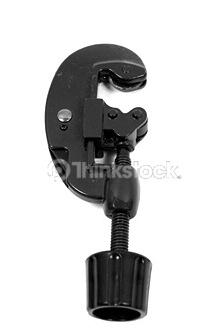
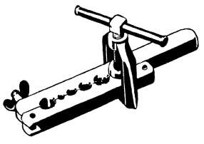
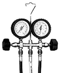
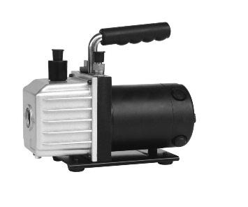


6 SUGGESTED TOOLS Standard Wrench Adjustable/Crescent Wrench Torque Wrench Hex Keys or Allen Wrenches Drill & Drill Bits Hole Saw Pipe Cutter Screw drivers (Phillips & Flat blade) Manifold and Gauges Level R410A Flaring Tool Clamp on Amp Meter Vacuum Pump Safety Glasses Work Gloves Refrigerant Scale Micron Gauge 5
7 INSTALLATION SITE INSTRUCTIONS Step 1 Installation Site of Indoor Unit Select a site that allows for the following: Ensure the installation complies with the installation minimum dimensions and meets the minimum and maximum connecting piping length and maximum change in elevation. Air inlet and outlet will be clear of obstructions, ensuring proper airflow throughout the room. Condensate can be easily and safely drained. All connections can be easily made to outdoor unit. Indoor unit is out of reach of children. A wall strong enough to withstand the full weight and vibration of the unit. Filter can be easily accessed for cleaning. Leave enough free space to allow access for routine maintenance. Install at least 10 ft. (3 m) away from the antenna of TV set or radio. Operation of the air conditioner may interfere with radio or TV reception in areas where reception is weak. An amplifier may be required for the affected device. Do not install in a laundry room or by a swimming pool. Installation Site of Outdoor Unit Select a site that allows for the following: Outdoor location meets all minimum installation distances defined in the Installation Dimensions section. Sound from outdoor unit will not annoy neighbors. All connections can be easily made to indoor unit. Air inlet and outlet will be clear of obstructions to ensure proper airflow. Wall or roof is strong enough to withstand the full weight and vibration of the outdoor unit (for wall or roof installation only). Outdoor unit is out of reach of children and does not obstruct walkways. Outdoor unit is not exposed to direct sunlight or strong wind. Maintenance and repairs can be easily performed on the outdoor unit. Ensure the installation complies with the minimum and maximum connecting piping length and maximum change in elevation criteria. 6
8 INSTALLATION DIMENSIONS Indoor unit 2 3 Part Name 4 1. Remote Controller 2. Front Panel 3. Air Filter 4. Swing Louvers 5. Insulation 6. Refrigerant Pipes 7. Refrigerant Pipes 8. Drain Hose Outdoor unit 7 8 7
 Floor Minimum outdoor clearances Air inlet Air outlet Outdoor Unit Minimum Distances in (mm) A 20 (500) B 20 (500) C 24")
9 INSTALLATION DIMENSIONS Minimum indoor clearances Ceiling 6 in (0.15m) 5 in (0.13m) 5 in (0.13m) 6 ft (1.8m) Floor Minimum outdoor clearances Air inlet Air outlet Outdoor Unit Minimum Distances in (mm) A 20 (500) B 20 (500) C 24 (610) D 12 (305) E 12 (305) 8
10 INSTALLATION OF INDOOR UNIT Step 2 Installation of Mounting Bracket 1. Attach the mounting bracket to the indoor unit. 2. Find the horizontal center of the indoor unit. 3. Mark the center of the indoor unit on mounting bracket for future reference. NOTE: The center of the mounting bracket is not the center of the indoor unit. 4. Remove the mounting brackets from the indoor unit and position the mounting bracket on the wall in desired location. Use centering mark on mounting bracket for centering the indoor unit on the wall. 5. Mounting bracket must be installed horizontally and level right to left. NOTE: Condensate drain pan has built-in pitch for proper drainage. 6. Secure mounting bracket to wall with a minimum of five screws, evenly spaced to properly support indoor unit weight. NOTE: It is recommended to install screw anchors for sheet rock, concrete block, brick and such type of walls. 9
11 INSTALLATION OF INDOOR UNIT Mounting Bracket Diagrams and Dimensions Left (Rear piping hole) 09K and 12K Unit Right (Rear piping hole) Left (Rear piping hole) 18K Size Unit Right (Rear piping hole) Left (Rear piping hole) 24K Size Unit Right (Rear piping hole) 10
12 INSTALLATION OF INDOOR UNIT Step 3 Drill Hole in Wall for Interconnecting Piping, Drain & Wiring If indoor unit refrigerant piping is going to exit from the rear: 1. It is recommended that the refrigerant pipe flare connectors extend through the wall to the outside. In some situations field-fabricated piping extensions will be required to extend the indoor unit refrigerant flare connections to the outside of the wall. 2. Use mounting bracket diagrams and dimensions to find and mark the proper location for the wall hole. If refrigerant piping is going through the right or left side of front panel: 1. Use a small saw blade to carefully cut a U-shaped hole in the side of the front panel. The hole must be large enough for refrigerant pipes, condensate hose and wires. 2. Determine and mark proper location for wall hole. 3. Use table below to determine recommended wall hole size for your unit size. Table of Wall Hole Size per Unit Size Unit Size Wall Hole Size (Diameter) (BtuH) in mm 9, / , / , / , / Cut the wall hole with a 5 to 10 downward slant to the outdoors. 5. Insert a wall hole sleeve into hole to prevent damage to refrigerant pipes, insulation, condensate drain hose and wiring. 6. Seal around wall hole sleeve with caulk or foam to weatherproof. Indoor Wall Hole Sleeve Outdoor Seal Hole Hole Size Wall Hole Diagram 11
13 OUTDOOR UNIT PREPARATION Step 4 Install Ground Pad or Wall Hangers 1. Determine proper location for outdoor unit. 2. Follow all instructions provided by manufacturer for installing wall hangers or ground pad. 3. Verify the wall hangers or ground pad can safely support the weight of the outdoor unit. 4. Verify the wall hangers or ground pad is level and meets all outdoor dimensional clearances. Install Outdoor Unit Risers If the outdoor unit requires added elevation above the ground, installing riser legs will provide a sturdy and stable solution. Follow all instructions provided by manufacturer for installing riser legs to outdoor unit. NOTE: Riser legs will also help absorb vibrations and noise while facilitating proper drainage. WARNING Florida Wind Load Requirements state that outdoor unit must be anchored to concrete pad using four 3/8-in diameter Power Wedge Bolt Plus (or equivalent) with 1-in diameter fender washers. Anchor bolts must be embedded into 3,000 PSI minimum concrete at a distance of 4 1/2-in from any concrete edge. The concrete thickness must exceed 1.5 times the anchor depth. Install Condensate Drain for Outdoor Unit During normal heating and defrost operation, the outdoor unit will generate condensate water. The condensate water should be routed to a safe location through the drain hose. 1. Locate drain hole on bottom of outdoor unit. 2. Install the outdoor drain fitting into hole on the bottom of outdoor unit as shown. 3. Connect the drain hose to drain fitting. 4. Route drain hose to safe location for proper drainage of excess condensate water. Drain Fitting Installation 12
14 INSTALLATION OF REFRIGERANT PIPING Step 5 Piping Connections to Outdoor Unit CAUTION Use refrigeration grade tubing ONLY. No other type of tubing may be used. Use of other types of tubing will void manufacturer s warranty. Make sure there is enough piping to cover the required length between the outdoor and indoor unit. Piping Preparation Do not open service valves or remove protective caps from tubing ends until all connections are made. Keep tubing free of dirt, sand, moisture and contaminants. Insulate each refrigerant pipe and condensate hose with minimum 3/8 (10 mm) wall thermal pipe insulation. NOTE: Insulate condensate hose to prevent sweating which may cause water stains or wall damage. Bind refrigerant pipes, condensate hose and interconnecting wire together with cable ties at 12 inch intervals. Piping and Drain Hose Connections to Indoor Unit NOTE: For maximum serviceability, it is recommended to have refrigerant pipe flare connections and the drain connection on the outside. 1. Feed refrigerant pipes, drain hose and interconnecting wires assembly through wall hole from outdoor to the indoor space. 2. Set the indoor unit on mounting bracket. Allow the indoor unit to hinge on the top of the mounting bracket. Do not lock down bottom of unit to mounting bracket. 3. Adjust the length of the interconnecting wires so that it can easily reach the indoor unit electrical control box. Route and fit the interconnecting wires into back side of indoor unit. 13

15 INSTALLATION OF REFRIGERANT PIPING 4. Open front cover of indoor unit and remove field wiring terminal block cover. Route the interconnecting wires to terminal block in control box. 5. Allow interconnecting wires to hang free. Wire connections will be handled later in these instructions. 6. Adjust the length of condensate drain hose to easily meet the drain pipe of the indoor unit. Seal and insulate hose connection to prevent leaks and sweating. NOTE: Prevent condensate drain hose from sagging or kinking for proper drainage. 7. Adjust the length and carefully bend refrigerant pipes to meet indoor unit refrigerant pipe connections with proper tools to avoid kinks. 8. Apply a small amount of refrigerant oil to the flare connection on the refrigerant pipes. Field Wiring Cover Interconnecting Wiring 9. Properly align piping and tighten flare nut using a standard wrench and a torque wrench as shown in figure to the right: Indoor Unit Piping Taper Nut Piping Wrench Torque Wrench 10. Carefully tighten flare nuts to correct torque level referring to the following Torque Table: Torque Table Pipe Diameter Nut Size Tightening Torque inch (mm) inch (mm) ft-lbs N-m 1/4 (6.35) 1/4 (17) 10 to to 18 3/8 (9.5) 3/8 (22) 25 to to 42 1/2 (12.7) 1/2 (25) 36 to to 61 5/8 (15.9) 5/8 (29) 50 to to 82 NOTE: Over tightening may damage flare connections and cause leaks. 11. Apply insulation to refrigerant pipe joints to prevent sweating. 12. Gently and securely lock down bottom of indoor unit to wall mounting bracket. 14

16 INSTALLATION OF REFRIGERANT PIPING Step 6 Piping Connections to Outdoor Unit 1. Remove service valve cover (if provided) to access the service valves and refrigerant ports. 2. Carefully bend and adjust length of refrigerant pipes to meet outdoor unit service valves connections with proper tools to avoid kinks. Service Valve Cover NOTE: Use proper techniques to cut and re-flare refrigerant pipes, if required. An R410A Flaring Tool is required for re-flaring refrigerant pipes. 3. Apply a small amount of refrigerant oil to the flare connection on the refrigerant pipe. 4. Properly align piping and tighten flare nut using a standard wrench and a torque wrench as shown in the indoor piping section. 5. Carefully tighten flare nuts to correct torque level referring to the following Torque Table: Torque Table Pipe Diameter Nut Size Tightening Torque inch (mm) inch (mm) ft-lbs N-m 1/4 (6.35) 1/4 (17) 10 to to 18 3/8 (9.5) 3/8 (22) 25 to to 42 1/2 (12.7) 1/2 (25) 36 to to 61 5/8 (15.9) 5/8 (29) 50 to to 82 NOTE: Over tightening may damage flare connections and cause leaks. 15
17 INSTALLATION OF POWER AND WIRING Step 7 Indoor Unit Interconnecting Wire Connections WARNING Disconnect all electrical power to unit including disconnects, fuses and circuit breakers. 1. Open front cover of indoor unit and remove field wiring terminal block cover. 2. Pull interconnecting wires up from back of indoor unit and position in close to the terminal block on indoor unit. NOTE: The indoor unit is powered from the outdoor unit, depending on local code, a disconnect switch may need to be installed to a power supply circuit. 3. Connect wiring to indoor unit per connection diagram. NOTE: Record wire colors and terminal references for uses with Outdoor Unit wire connections. 4. Replace field wiring cover and close front cover of indoor unit. 16
18 INSTALLATION OF POWER AND WIRING Step 8 Outdoor Unit Wire Connections WARNING Disconnect all electrical power to unit including disconnects, fuses and circuit breakers. 1. Remove the service panel on right side of the outdoor unit. 2. Insert interconnecting wires and main power wires through the wire holes on conduit mounting bracket. 3. Secure main power conduit (and interconnecting wire conduit, if required) with locking nuts to conduit mounting bracket. Cable Cross Board Wire Hole 4. Open wire clamp/strain relief and adjust wire lengths for proper connections to the outdoor unit terminal block. Indoor Unit N1 2 3 GND Blue Black Brown Grn/Yel Outdoor Unit N(1) L L2 GND GND Black White Grn/Yel L1 L2 GND Wiring Diagram 9K and 12K BtuH (230V Models) Interconnecting Wires Main Power Wires 17
19 INSTALLATION OF POWER AND WIRING Indoor Unit N(1) 2 3 GND Blue Black Brown Grn/Yel Interconnecting Wires Wiring Diagram 18K and 24K BtuH Outdoor Unit N(1) 2 3 L1 L2 GND Black White Grn/Yel Main Power Wires L1 L2 GND 5. Following the same wire colors and terminal references from the indoor unit, tightly connect interconnecting wires to the outdoor unit terminal block per wiring diagram above. NOTE: Crossing interconnecting wires will cause system malfunction and possible damage. 6. Tightly connect main power wires to outdoor unit terminal block per wiring diagram above. 7. Secure all wires inside wire clamp/strain relief. Verify wires are secure, not loose and no external force on wires affects the connections at the terminals. 8. Replace service panel on right side of the outdoor unit. 9. Connect main power wires and conduit to unit disconnect switch box per manufacturer s instructions, National Electrical Code (NEC) and local electrical codes. CAUTION Electrical Disconnecting means must be provided and shall be located within sight and readily accessible from the unit. Failure to follow this caution may result in equipment damage or improper operation. All wires running from the indoor to outdoor unit must comply with National Electrical Code (NEC) and local codes. No wire should be allowed to touch refrigerant tubing, compressor or any moving parts. All wires must be connected firmly to terminal block to avoid unit malfunction, overheating and possible fire hazard. 18
20 VACUUM TESTING Step 9 Leaking Test 1. Connect the charging hose of the manifold valve to charge the end of the low-pressure valve. 2. Add dry nitrogen to a pressure of 200 lbs. Tightly close both high- and low-pressure valves. 3. Leak-test flare fittings with soap bubbles. If no leak is detected, release nitrogen. Step 10 System Vacuum and Charge CAUTION UNIT DAMAGE HAZARD Never use the system compressor as a vacuum pump. It may result in equipment damage or improper system operation. Refrigerant pipes and indoor coil should be evacuated using the recommended deep vacuum method of 500 microns. The alternate triple evacuation method may be used if the procedure outlined below is followed. NOTE: Alway break a vacuum with dry nitrogen. Using Vacuum Pump 1. Completely tighten flare nuts A, B, C, D, connect manifold gage charge hose to a charge port of the low side service valve. 2. Connect charge hose to vacuum pump. 3. Fully open the low side of manifold gage. See figure at right. 4. Start vacuum pump. Outdoor Unit Service Valve Refrigerant Indoor Unit Low Side High Side Manifold Gauge 500 microns Low Side Valve High Side Valve Charge Hose Charge Hose Vacuum Pump Low Side Valve 19
21 VACUUM TESTING 5. Evacuate using either deep vacuum or triple evacuation method. 6. After evacuation is complete, fully close the low side of manifold gage and stop operation of vacuum pump. 7. The factory charge contained in the outdoor unit is good for up to 25 ft. (8 m) of line length. NOTE: For refrigerant lines longer than 25 ft (8 m), add add l refrigerant per foot of extra piping up to the maximum allowable length. See System Requirement section on page 4 for more info 8. Disconnect charge hose from charge connection of the low side service valve. 9. Fully open service valves B and A. 10. Securely tighten caps of service valves. Deep Vacuum Method The deep vacuum method requires a vacuum pump capable of pulling a vacuum of 500 microns and a vacuum gage capable of accurately measuring this vacuum depth. The deep vacuum method is the most positive way of assuring a system is free of air and liquid water Leak in System Vacuum Tight too Wet Tight Dry System Deep Vacuum Graph 20
22 START-UP Step 11 Fig. a Installing Photocatalytic Filter (optional) 1. Lift front panel and remove air filter. (Fig. a). 2. Attach photocatalytic filter onto air filter. (Fig. b). 3. Install air filter as shown; close panel. (Fig. c). Air Filter Fig. b Photocatalytic Filter Step 12 Fig. c Start-up and Checkout Test Operation Perform test operation after completing gas leak and electrical safety check. 1. Turn on electrical disconnect to outdoor unit. 2. Push the ON/OFF button on Remote Control to begin testing. NOTE: A protection feature prevents the system from being activated for approx. 3 minutes. 3. Push MODE button, select COOLING, HEATING, FAN mode to confirm all functions. System Checks 1. Conceal refrigerant pipes where possible. 2. Make sure drain hose slopes downward along entire length. 3. Ensure all refrigerant pipes and connections are properly insulated. 4. Fasten pipes to outside wall, when possible. 5. Seal and weatherproof wall hole which the interconnecting wires and refrigerant pipes pass through. Indoor Unit 1. Do all Remote Control buttons function properly? 2. Do the display panel lights work properly? 3. Does the swing louver function properly? 4. Does the drain work? Outdoor Unit 1. Push the mode button to COOL and adjust the room setting to 61 F deg. Wait up to 3 minutes from compressor time guard. Does compressor and outdoor fan turn on in cooling mode? 2. Push the mode button to HEAT and adjust the room setting to 85 F deg. Wait up to 3 minutes for compressor time guard. Does compressor and outdoor fan turn on in heat mode? 21
23 START-UP AND TROUBLESHOOTING Explain Following Items To Customer With The Aid Of The Owner s Manual: 1. How to turn system on and off; selecting COOLING, HEATING and other operating modes; setting a desired temperature; setting the timer to automatically start and stop system operation; and all other features of the Remote Control and display panel. 2. How to remove and clean the air filter. 3. How to set air with the swing louvers. 4. Explain care and maintenance. 5. Present the Owner s Manual and installation instructions to customer. Troubleshooting This unit has onboard diagnostics. Error codes will appear on the LED display on the front panel of the indoor unit in place of the temperature display. The table below explains the error codes for both units. DIAGNOSTIC CODES Equipment Fault Error Codes Possible Causes Indoor Configuration Jumper Indoor/Outdoor Mismatch High Current Protection Communication Error Indoor Air Temp. Thermistor Indoor Coil Temp. Thermistor Outdoor Air Temp. Thermistor Outdoor Coil Temp. Thermistor Compressor Discharge Temp. Thermistor Compressor Overload Protection IPM Module Protection Indoor Fan Malfunction Compressor Synchronism 4-Way Valve Malfunction C5 LP E5 E6 F1 F2 F3 F4 F5 H3 H5 H6 H7 U7 Missing Configuration Jumper on Indoor Control Board Indoor and Outdoor Units Do Not Match (Model or Capacity) Power Supply is not Stable and Voltage Range is too Large Mis-wired or Communication Failure Bad Connection, or Indoor Air Sensor Failure Bad Connection, or Indoor Coil Sensor Failure Bad Connection, or Outdoor Ambient Sensor Failure Bad Connection, or Outdoor Coil Sensor Failure Bad Connection, or Discharge Sensor Failure Low Refrigerant Charge, Blocked Capillary, or Compressor Motor Failure IPM Module Temperature Too High, High Ambient, Low Voltage, or Bad Connections Indoor Fan Stopped or Running too Slow High Pressure, Low Voltage, or Bad Connections Bad Connection, Solenoid Failure, or Valve Malfunction. ( Heat Pumps Only) High Pressure Protection E1 Too much refrigerant or High Ambient conditions or low airflow. 22
24 GREE ELECTRIC APPLIANCES, INC. PRODUCT & INSTALLATION RECORD For your convenience, please record the model and serial numbers of your new equipment in the spaces provided. This information, along with the installation data and dealer contact information, will be helpful should your system require maintenance or service. UNIT INFORMATION Model No. Serial No. INSTALLATION INFORMATION Date Installed: DEALERSHIP/INSTALLER INFORMATION Company Name: Address: Phone Number: Technician Name: Gree Electric Appliances, Inc 2015 Cat No: DFS-TERRA-HP-3IN
HIGH-WALL DUCTLESS AIR CONDITIONING & HEATING SYSTEM INSTALLATION MANUAL
 HIGH-WALL DUCTLESS AIR CONDITIONING & HEATING SYSTEM INSTALLATION MANUAL Models: RIO09HP115V1A RIO12HP115V1A RIO09HP230V1B RIO12HP230V1B RIO18HP230V1B RIO24HP230V1A Thank you for choosing a Rio Heat Pump
MULTI HEAT PUMP INSTALLATION MANUAL DUCTLESS INVERTER. Models: MULTI18HP230V1AO MULTI24HP230V1AO MULTI30HP230V1AO MULTI36HP230V1AO MULTI42HP230V1AO
 MULTI DUCTLESS INVERTER HEAT PUMP INSTALLATION MANUAL Models: MULTI18HP230V1AO MULTI24HP230V1AO MULTI30HP230V1AO MULTI36HP230V1AO MULTI42HP230V1AO Thank you for choosing a Gree Multi Ductless Heat Pump
HIGH-WALL DUCTLESS AIR CONDITIONING & HEATING SYSTEM INSTALLATION MANUAL
 HIGH-WALL DUCTLESS AIR CONDITIONING & HEATING SYSTEM INSTALLATION MANUAL Models: VIR09HP115V1B VIR12HP115V1B VIR09HP230V1B VIR12HP230V1B VIR18HP230V1B VIR24HP230V1B VIR30HP230V1B VIR36HP230V1B Thank you
WALL MOUNT DUCTLESS AIR CONDITIONING & HEATING SYSTEM INSTALLATION MANUAL
 WALL MOUNT DUCTLESS AIR CONDITIONING & HEATING SYSTEM INSTALLATION MANUAL Models: SAP09HP230V1AO SAP12HP230V1AO SAP18HP230V1AO SAP24HP230V1AO SAP09HP230V1AH SAP12HP230V1AH SAP18HP230V1AH SAP24HP230V1AH
TABLE OF CONTENTS. NOTE: Read the entire instruction manual before starting the installation. TROUBLESHOOTING... 13
 R 410A Duct Free Split System Air Conditioner and Heat Pump Product Family: DFS4(A/H) System, DFC4(A/H)3 Outdoor, DFF4(A/H)H Indoor NOTE: Read the entire instruction manual before starting the installation.
Installation Instructions
 8GXM / 0GXM Multi---Split High---Wall Duct Free Split System 8GXM --- Size 18k, k, and 0k 0GXM --- Size 9k, 1k, and 18k Installation Instructions NOTE: Read the entire instruction manual before starting
Installation Instructions
 38MHR Outdoor Unit Single Zone Ductless System Sizes 09 to 24 Installation Instructions NOTE: Read the entire instruction manual before starting the installation. NOTE: Images are for illustration purposes
DLCLRA. INSTALLATION INSTRUCTIONS Outdoor Unit Single Zone Ductless System Sizes 36 to 58 TABLE OF CONTENTS
 DLCLRA INSTALLATION INSTRUCTIONS Outdoor Unit Single Zone Ductless System Sizes 36 to 58 Fig. 1 - Size 36 TABLE OF CONTENTS PAGE SAFETY CONSIDERATIONS... 2 PARTS LIST... 3 SYSTEM REQUIREMENTS... 4 WIRING...
Installation Instructions
 40MAQ High Wall Ductless Split System Sizes 09 to 36 Installation Instructions NOTE: Read the entire instruction manual before starting the installation TABLE OF CONTENTS PAGE SAFETY CONSIDERATIONS 2 PARTS
Installation Instructions
 40MBFQ Floor Console Ductless System Sizes 09 to 58 Installation Instructions TABLE OF CONTENTS PAGE SAFETY CONSIDERATIONS... 2 PARTS LIST... 3 SYSTEM REQUIREMENTS... 4 WIRING... 4 DIMENSIONS... 5 CLEARANCES...
Installation Instructions
 38MPRA Outdoor Unit Single Zone Ductless System Sizes 09 to 12 Installation Instructions NOTES: Read the entire instruction manual before starting the installation. Images are for illustration purposes
DLCSRA. INSTALLATION INSTRUCTIONS Outdoor Unit Ductless Split System Sizes 09 to 36 TABLE OF CONTENTS
 DLCSRA INSTALLATION INSTRUCTIONS Outdoor Unit Ductless Split System Sizes 09 to 36 NOTES: Read the entire instruction manual before starting the installation. Images are for illustration purposes only.
Installation Instructions
 40MBFQ Floor Console Ductless System Sizes 09 to 12 Installation Instructions TABLE OF CONTENTS PAGE SAFETY CONSIDERATIONS... 2 PARTS LIST... 3 SYSTEM REQUIREMENTS... 4 DIMENSIONS... 5 CLEARANCES... 5
Installation Instructions
 38MGQ Multi-Zone Ductless System Sizes 18, 27, 36 and 48 Installation Instructions NOTE: Read the entire instruction manual before starting the installation. TABLE OF CONTENTS PAGE SAFETY CONSIDERATIONS...
Installation Instructions
 40MAQ / 38MAQ 619PB / 538PR High---Wall Ductless Split System Sizes 09 to 30 Installation Instructions TABLE OF CONTENTS PAGE PARTS LIST... 2 SAFETY CONSIDERATIONS... 3 SYSTEM REQUIREMENTS... 4 DIMENSIONS...
Installation Instruction
 40GRQ / 619FB / 38GRQ / 538FR High- Wall Ductless Split System Sizes 09-18 Installation Instruction NOTE: Read the entire instruction manual before starting the installation. TABLE OF CONTENTS PAGE SAFETY
Installation Instruction
 DLFCAB / DLCCAR / DLFCHB / DLCCHR DLFDAB / DLCDAR / DLFDHB / DLCDHR High- Wall Ductless Split System Sizes 09-36 Installation Instruction NOTE: Read the entire instruction manual before starting the installation.
SLIM CONCEALED DUCT AIR CONDITIONING & HEATING SYSTEM INSTALLATION MANUAL. Models:
 SLIM CONCEALED DUCT AIR CONDITIONING & HEATING SYSTEM INSTALLATION MANUAL Models: Indoor Unit UMAT18HP230V1AD UMAT24HP230V1AD UMAT30HP230V1AD UMAT36HP230V1AD UMAT42HP230V1AD UMAT48HP230V1AD Outdoor Unit
INSTALLATION INSTRUCTIONS R 410A
 R 410A Ductless Split System Air Conditioner and Heat Pump MODELS: DLC4(A/H) Outdoor, DLF4(A/H) SIZES: 9K, 12K, 18K, 24K, 30K, and 36K NOTE: Read the entire instruction manual before starting the installation.
DLCMRA. INSTALLATION INSTRUCTIONS Multi zone Outdoor Unit Ductless System Sizes 18, 27, 36 and 48 TABLE OF CONTENTS PAGE SAFETY CONSIDERATIONS...
 DLCMRA INSTALLATION INSTRUCTIONS Multi zone Outdoor Unit Ductless System Sizes 18, 27, 36 and 48 TABLE OF CONTENTS PAGE SAFETY CONSIDERATIONS... 2 GENERAL... 2 PARTS LIST... 3 SYSTEM REQUIREMENTS... 4
Installation Instructions
 40MAQ High Wall Ductless System Sizes 09 to 36 Installation Instructions NOTES: Read the entire instruction manual before starting the installation. Images are for illustration purposes only. Actual models
Installation Instructions
 40MBD Ducted Style Ductless System Sizes 09 to 48 Installation Instructions NOTE: Read the entire instruction manual before starting the installation. TABLE OF CONTENTS PAGE SAFETY CONSIDERATIONS... 2
Installation Instructions
 40MHH High Wall Ductless System Sizes 09 to 24 Installation Instructions NOTE: Read the entire instruction manual before starting the installation. NOTE: Images are for illustration purposes only. Actual
DUCTLESS INVERTER HEAT PUMP INSTALLATION MANUAL. Models: MULTI18HP230V1CO MULTI24HP230V1CO MULTI30HP230V1CO MULTI36HP230V1CO MULTI42HP230V1CO
 DUCTLESS INVERTER HEAT PUMP INSTALLATION MANUAL Models: MULTI18HP230V1CO MULTI24HP230V1CO MULTI30HP230V1CO MULTI36HP230V1CO MULTI42HP230V1CO Thank you for choosing a Multi21 Ductless Heat Pump for your
Installation Instructions
 38MGR Multi-zone Outdoor Unit Ductless System Sizes 18, 24, 30, 36 and 48 Installation Instructions TABLE OF CONTENTS PAGE SAFETY CONSIDERATIONS... 2 GENERAL... 2 PARTS LIST... 3 SYSTEM REQUIREMENTS...
ALICE HIGH-WALL DUCTLESS AIR CONDITIONING & HEATING SYSTEM INSTALLATION MANUAL
 ALICE HIGH-WALL DUCTLESS AIR CONDITIONING & HEATING SYSTEM INSTALLATION MANUAL Models: GWH09QC-A3DNA1D (115V) GWH12QC-A3DNA1D (115V) GWH09QC-D3DNA1D (230V) GWH12QC-D3DNA1D (230V) GWH18QD-D3DNA1G (230V)
Installation Instructions
 40MBCQ Cassette Ductless System Sizes 09 to 8 Installation Instructions TABLE OF CONTENTS PAGE SAFETY CONSIDERATIONS... PARTS LIST... 3 SYSTEM REQUIREMENTS... 4 DIMENSIONS INDOOR... 5 CLEARANCES INDOOR...
Ductless Split Air Conditioner
 Ductless Split Air Conditioner Installation Manual Indoor HSU09VHG(DB)-W HSU12VHG(DB)-W HSU18VHH(DB)-W HSU24VHG(DB)-W Outdoor HSU09VHG(DB)-G HSU12VHG(DB)-G HSU18VHH(DB)-G HSU24VHG(DB)-G Table of Contents
INSTALLATION MANUAL. Split-type Air Conditioner (Cooling and Heating) Outdoor Unit UQB09JJWC UQB12JJWC. Indoor Unit AQB09JJWC AQB12JJWC
 Outdoor Unit UQB09JJWC UQB12JJWC. Indoor Unit AQB09JJWC AQB12JJWC") AQB09JJ6WC_IM_E_2585 2006.4.17 4:26 PM Page 17 INSTALLATION MANUAL Indoor Unit AQB09JJWC AQB12JJWC Outdoor Unit UQB09JJWC UQB12JJWC ENGLISH FRANÇAIS ESPAÑOL Split-type Air Conditioner (Cooling and Heating)
AQB09JJ6WC_IM_E_2585 2006.4.17 4:26 PM Page 17 INSTALLATION MANUAL Indoor Unit AQB09JJWC AQB12JJWC Outdoor Unit UQB09JJWC UQB12JJWC ENGLISH FRANÇAIS ESPAÑOL Split-type Air Conditioner (Cooling and Heating)
INSTALLATION MANUAL. Split-type Air Conditioner (Cooling and Heating) Indoor Unit AQB18J6WC AQB24J2WC. Outdoor Unit UQB18J6WC UQB24J2WC
 Indoor Unit AQB18J6WC AQB24J2WC. Outdoor Unit UQB18J6WC UQB24J2WC") AQB8J6WC_IM_E_25864 2006.4.4 3:29 PM Page 7 INSTALLATION MANUAL Indoor Unit AQB8J6WC AQB24J2WC Outdoor Unit UQB8J6WC UQB24J2WC ENGLISH FRANÇAIS ESPAÑOL Split-type Air Conditioner (Cooling and Heating)
AQB8J6WC_IM_E_25864 2006.4.4 3:29 PM Page 7 INSTALLATION MANUAL Indoor Unit AQB8J6WC AQB24J2WC Outdoor Unit UQB8J6WC UQB24J2WC ENGLISH FRANÇAIS ESPAÑOL Split-type Air Conditioner (Cooling and Heating)
INSTALLATION MANUAL COMFORT...BUILT TO LAST. 9,000, 12,000 and 18,000 BTU SINGLE-ZONE DUCTLESS MINI-SPLIT SYSTEM Heat Pump
 COMFORT...BUILT TO LAST 9,000, 12,000 and 18,000 BTU SINGLE-ZONE DUCTLESS MINI-SPLIT SYSTEM Heat Pump INSTALLATION MANUAL INDOOR UNIT: 1PAMSH09-SZW-14.5 1PAMSH09-SZW-15 1PAMSH12-SZW-15 1PAMSH18-SZW-15
Split Air Conditioner
 Change for Life Split Air Conditioner Installation Manual Residential Air Conditioners MODEL: GWC09AB-D3DNA2D GWC12AB-D3DNA2D GWC18AC-D3DNA2D GWC24AC-D3DNA2D GWH09AB-D3DNA2D GWH12AB-D3DNA2D GWH18AC-D3DNA2D
INVERTER SPLIT - TYPE
 INVERTER SPLIT - TYPE ISSUE No 2 DATE 04/09/08 P/No 2020323A2868 CONTENTS SAFETY PRECAUTIONS Warning 2 Operating temperature 2 BEFORE INSTALLATION Tools needed for installation 3 Items required for installing
Horizontal/Side Discharge Condensing Units
 INSTALLATION, OPERATION & MAINTENANCE MANUAL Horizontal/Side Discharge Condensing Units Models CMA12SD-0 CMA18SD-1 CMA24SD-1 CMA30SD-1 CMA36SD-1 CMA48SD-1 517.787.2100 www.marsdelivers.com Horizontal/Side
WineZone Ceiling Mount Ductless Split 15
 WineZone Ceiling Mount Ductless Split 15 Requires an HVAC technician to install and charge with R-22 refrigerant. Easy to install. Unit plugs into wall outlet. Industrial grade unit for longer life. Indoor
ROOM AIR CONDITIONER INSTALLATION MANUAL
 ROOM AIR CONDITIONER INSTALLATION MANUAL (Inverter Split Type) Please read this installation manual completely before installing the product When the power cord is damaged, replacement work shall be performed
INSTALLATION INSTRUCTIONS
 INSTALLATION INSTRUCTIONS - Wall-mount indoor unit - OPERATING LIMITS Cooling Maximum conditions Heating Maximum conditions Outdoor temperature : 122 F (50 C) D.B. Outdoor temperature : 75 F (24 C) D.B.
INSTALLATION INSTRUCTIONS Cased N Coil, Horizontal ENH4X
 INSTALLATION INSTRUCTIONS Cased N Coil, Horizontal ENH4X NOTE: Read the entire instruction manual before starting the installation. TABLE OF CONTENTS PAGE SAFETY CONSIDERATIONS... 1 INTRODUCTION... 1 INSTALLATION...
SINGLE - ZONE Ductless Split System Heat Pumps Installation, Operation & Maintenance Manual
 Presents SINGLE - ZONE Ductless Split System Heat Pumps Installation, Operation & Maintenance Manual 9k,12k 18k 24k, 30k, 36k ECR International, Inc. 2201 Dwyer Avenue, Utica NY 13501 Phone: 800.325.5479
VMH09/12/18/24 SU Series
 Installation and Operation Manual VMH09/12/18/24 SU Series Inverter Single Zone Ductless Mini-Split 517.787.2100 www.marsdelivers.com www.heatcontroller.com TABLE OF CONTENTS Safety Precautions Warnings
WMHP Series R410a Heat Pump INSTALLATION INSTRUCTIONS
 WMHP Series R410a Heat Pump INSTALLATION INSTRUCTIONS **WARNING TO INSTALLER, SERVICE PERSONNEL AND OWNER** Altering the product or replacing parts with non authorized factory parts voids all warranty
Installation Manual. KS Series KS09 KS12 KS18 KS24 KS28. J3387_Kaden_Installer_Manual_ indd 1
 Wall Mounted AIR CONDITIONER Installation Manual KS Series KS09 KS12 KS18 KS24 KS28 J3387_Kaden_Installer_Manual_050917.indd 1 5/09/2017 9:07 AM J3387_Kaden_Installer_Manual_050917.indd 2 5/09/2017 9:07
Residential Piping and Long Line Guideline
 AC / HP R-410A Refrigerant Systems Single-Stage, Two-Stage and Variable Speed Models Residential Piping and Long Line Guideline TABLE OF CONTENTS Safety Considerations... 2 Definitions... 2 Introduction...
Split Air Conditioner
 Change for Life Split Air Conditioner Installation Manual Residential Air Conditioners MODEL: GWH09MA-A3DNXXA GWC09MA-A3DNXXA GWH12MB-A3DNXXA GWC12MB-A3DNXXA GWH09MB-D3DNXXD GWC09MB-D3DNXXD GWH12MB-D3DNXXD
DVC/DVH Series. Inverter Single Zone Ductless Mini-Split A-DVC/DVH 09SF A-DVC/DVH 12SF A-DVC/DVH 18SF A-DVC/DVH 24SF
 Installation Manual DVC/DVH Series Inverter Single Zone Ductless Mini-Split A-DVC/DVH 09SF A-DVC/DVH 12SF A-DVC/DVH 18SF A-DVC/DVH 24SF B-DVC/DVH 09SF B-DVC/DVH 12SF B-DVC/DVH 18SF B-DVC/DVH 24SF www.marsdelivers.com
CENTRAL AIR CONDITIONER SPLIT SYSTEM
 CENTRAL AIR CONDITIONER SPLIT SYSTEM WITH ELECTRONIC CONTROL SERIES: DS INSTALLATION INSTRUCTIONS INDEX GENERAL... 2 UNIT LOCATION CRITERIA... 2 DIMENSIONAL DRAWINGS... 3 INDOOR UNIT INSTALLATION... 5
Installation Instructions
 Installation Instructions KFN 9855 ide en - CA Installation, repair and maintenance work should be performed by a Miele authorized service technician in accordance with national and local safety regulations
INSTALLATION INSTRUCTIONS Cased N Coil, Horizontal ENH4X
 INSTALLATION INSTRUCTIONS Cased N Coil, Horizontal ENH4X NOTE: Read the entire instruction manual before starting the installation. TABLE OF CONTENTS PAGE SAFETY CONSIDERATIONS... 1 INTRODUCTION... 1 INSTALLATION...
Choosing the installation site. Installation. 07 Choosing the installation site
 Installation Installation warnings: 1. Carefully read the installation manual before beginning. 2. Follow each step as shown. 3. Observe all local, state, and national electrical codes and by qualified,
INSTALLATION INSTRUCTIONS Cased N Coil, Horizontal ENH4X
 INSTALLATION INSTRUCTIONS Cased N, Horizontal ENH4X NOTE: Read the entire instruction manual before starting the installation. SAFETY CONSIDERATIONS Improper installation, adjustment, alteration, service,
OWNER S AND INSTALLATION MANUAL RAV-480FS2B/RAV-480AS2B RAV-600FS8B/RAV-600AS8B
 OWNER S AND INSTALLATION MANUAL RAV-480FS2B/RAV-480AS2B RAV-600FS8B/RAV-600AS8B P/N: 52FS2B54070-R CONTENTS PRECAUTIONS Important Safety Information Hints For Economical Operation Standard Safety Instructions
Installation Instructions
 CNPHP Cased N s Horizontal Heating --- Cooling Installation Instructions NOTE: Read the entire instruction manual before starting the installation. TABLE OF CONTENTS PAGE SAFETY CONSIDERATIONS... 1 INTRODUCTION...
R32. Installation Manual Split Type Wall Mounted Air Conditioner. This appliance shall be installed in accordance with: REFRIGERANT
 SWING LRSWING Installation Manual Split Type Wall Mounted Air Conditioner COOL RUN C SPEED TURBO ON/OFF FAN COOL HEAT SWING SWING Rinnai Systems Models System Indoor Outdoor HSNRQ25B HINRQ25B HONRQ25B
Installation Instructions. For the 18 Built-In Dishwasher and Front Color Panels
 Installation Instructions For the 18 Built-In Dishwasher and Front Color Panels Printed in USA 154232102 Before You Begin DO NOT INSTALL DISHWASHER UNTIL YOU HAVE READ ALL INSTRUCTIONS. FOR YOUR SAFETY,
1. BEFORE INSTALLATION
 ENGLISH SPLIT-TYPE AIR CONDITIONERS INSTALLATION MANUAL MSZ-FH09/12/15NA JG79A805H01 When installing multi units, refer to the installation manual of the multi unit for outdoor unit installation. Phillips
1. BEFORE INSTALLATION
 ENGLISH SPLIT-TYPE AIR CONDITIONERS INSTALLATION MANUAL MSZ-D30/36NA MSY-D30/36NA JG79A061H09 Phillips screwdriver Level Scale Utility knife or scissors 3 in. (75 mm) hole saw Torque wrench Wrench (or
Installation Instructions
 CNPHP Cased N Coils Horizontal Heating --- Cooling NOTE: Read the entire instruction manual before starting the installation. TABLE OF CONTENTS PAGE SAFETY CONSIDERATIONS... 1 INTRODUCTION... 1 INSTALLATION...
DUCTLESS MINI-SPLIT INSTALLATION MANUAL COMFORT...BUILT TO LAST
 COMFORT...BUILT TO LAST SINGLE ZONE DUCTLESS MINI-SPLIT INSTALLATION MANUAL 2PAMS SERIES Before using your air conditioner please read this manual carefully and keep it for future reference, along with
Installation and Operation Manual. SVH Series. Inverter Single Zone Ductless Mini-Split SVH09SA-0 SVH09SA-1 SVH12SA-0 SVH12SA-1 SVH18SA-1 SVH24SA-1
 Installation and Operation Manual SVH Series Inverter Single Zone Ductless Mini-Split SVH09SA-0 SVH09SA-1 SVH12SA-0 SVH12SA-1 SVH18SA-1 SVH24SA-1 www.marsdelivers.com Table of Contents Installation Manual
Installation Instructions
 EHNA Electric Heaters 5-20kW For 60 Hz Small Packaged Products MODELS: PAD3, PHD3, PAD4, PHD4, PAD5, PHD5, WPA3, WPH3 Installation Instructions NOTE: Read the entire instruction manual before starting
INSTALLER'S GUIDE. ALL phases of this installation must comply with NATIONAL, STATE AND LOCAL CODES
 11-AC11D2-5 INSTALLER'S GUIDE ALL phases of this installation must comply with NATIONAL, STATE AND LOCAL CODES Models: Condensing Units 2A7A5024-048, 2A7A4018-060, 2A7A2018-060 & 2A7A1018-060 IMPORTANT
Thank you very much for purchasing this Air Conditioner. Please read this use and installation instructions carefully before installing and using
 Thank you very much for purchasing this Air Conditioner. Please read this use and installation instructions carefully before installing and using this appliance and keep this manual for future reference.
INSTALLATION INSTRUCTIONS
 INSTALLATION INSTRUCTIONS Single Zone Mini-Split Inverter System FEATURING R-410A 15 SERIES Single Split Indoor Unit Outdoor Unit Heat Pump M4MHW15-A M4THS15-A Cooling Only M4MCW15-A M4TCS15-A 88-M4MHW15-1C-EN
Installation Instructions
 Installation Instructions Cased Horizontal Furnace Coil CK3B A96318 Fig. 1 Model CK3B Furnace Coil NOTE: Read the entire instruction manual before starting the installation. SAFETY CONSIDERATIONS Improper
Installation Manual. WAS / WYS Series. For 9,000-36,000 BTU/hr Systems. Inverter+ and Inverter++ Models
 DUCTLESS MINI SPLIT SYSTEM AIR CONDITIONER / HEAT PUMP WAS / WYS Series WAS: Cooling Only Version WYS: Cooling and Heating Version Inverter+ and Inverter++ Models For 9,000-36,000 BTU/hr Systems Installation
QUICK CONNECT INSTALLATION MANUAL DUCTLESS MINI-SPLIT SYSTEM FOR MODELS: 2PAMSHQC12 2PAMSHQC18 2PAMSHQC24 2PAMSHQC36
 QUICK CONNECT DUCTLESS MINI-SPLIT SYSTEM INSTALLATION MANUAL FOR MODELS: 2PAMSHQC12 2PAMSHQC18 2PAMSHQC24 2PAMSHQC36 Before using your air conditioner, please read this manual carefully and keep it for
MS8 SERIES CAUTION IMPORTANT IMPORTANT INSTALLATION AND SERVICE PROCEDURES MS8 SERIES UNITS MINI-SPLIT SINGLE-ZONE SYSTEMS (115V) TABLE OF CONTENTS
 TABLE OF CONTENTS") Corp. 1243-L9 Revised September 1, 2014 INSTALLATION AND SERVICE PROCEDURES MS8 SERIES MS8 SERIES UNITS MINI-SPLIT SINGLE-ZONE SYSTEMS (115V) TABLE OF CONTENTS MS8-CO Air Conditioner Outdoor Unit MS8-HO
Corp. 1243-L9 Revised September 1, 2014 INSTALLATION AND SERVICE PROCEDURES MS8 SERIES MS8 SERIES UNITS MINI-SPLIT SINGLE-ZONE SYSTEMS (115V) TABLE OF CONTENTS MS8-CO Air Conditioner Outdoor Unit MS8-HO
DAIKIN AIR CONDITIONER
 3P226011-1A M07B242A DAIKIN AIR CONDITIONER Two-dimensional bar code is a code for manufacturing. Safety Precautions (1) Read these Safety Precautions carefully to ensure correct installation. This manual
INSTALLATION INSTRUCTIONS
 INSTALLATION INSTRUCTIONS Inverter Split System Air Conditioner COOL/ DRY Model This air conditioner uses the new refrigerant R410A. Contents Page Model Combinations IMPORTANT! Please Read Before Starting...
1. BEFORE INSTALLATION
 ENGLISH SPLIT-TYPE AIR CONDITIONERS INSTALLATION MANUAL MSZ-D30/36NA MSY-D30/36NA JG79A061H01 Phillips screwdriver Level Scale Utility knife or scissors 3 in. (75 mm) hole saw Torque wrench Wrench (or
Inverter Air Conditioner Installation Manual GIN 090/GIN 091 GIN 120/GIN 121 GIN 180/GIN 181 GIN 240/GIN 241
 Inverter Air Conditioner Installation Manual GIN 090/GIN 091 GIN 120/GIN 121 GIN 180/GIN 181 GIN 240/GIN 241 Please read this user manual first! Dear Customer, Thank you for preferring a Beko product.
Installation Instructions
 50ES---A, 50EZ---A, 50VL---A, 50VG---A, 50VR---A, 50VT---A, 604D--- ---A, 607C--- ---A, 607E,--- ---A, 704D--- ---A, 707C--- ---A, 707E--- ---A PA3G --- --- A, PH3G --- --- A SMALL PACKAGED PRODUCTS Electric
Installation Instructions
 Installation Instructions For Fully Integrated NoFrost Combined Refrigerator-Freezers HC 2060/2061 7082 485-00 Important PLEASE READ AND FOLLOW THESE INSTRUCTIONS These instructions contain Warning and
1. BEFORE INSTALLATION
 ENGLISH SPLIT-TYPE AIR CONDITIONERS INSTALLATION MANUAL JG79A191H07 MSZ-GE06/09/12/15/18NA MSY-GE09/12/15/18NA When installing multi units, refer to the installation manual of the multi unit for outdoor
Installation Manual SPLIT-TYPE ROOM AIR CONDITIONER
 SPLIT-TYPE ROOM AIR CONDITIONER Installation Manual IMPORTANT NOTE: Read this manual carefully before installing or operating your new air conditioning unit. Make sure to save this manual for future reference.
MS8 SERIES CAUTION IMPORTANT IMPORTANT INSTALLATION AND SERVICE PROCEDURES MS8 SERIES UNITS MINI-SPLIT SINGLE-ZONE SYSTEMS ( V)
") Corp. 1244-L9 Revised April 26, 2016 INSTALLATION AND SERVICE PROCEDURES MS8 SERIES MS8 SERIES UNITS MINI-SPLIT SINGLE-ZONE SYSTEMS (208-230V) TABLE OF CONTENTS MS8-CO Air Conditioner Outdoor Unit MS8-HO
Corp. 1244-L9 Revised April 26, 2016 INSTALLATION AND SERVICE PROCEDURES MS8 SERIES MS8 SERIES UNITS MINI-SPLIT SINGLE-ZONE SYSTEMS (208-230V) TABLE OF CONTENTS MS8-CO Air Conditioner Outdoor Unit MS8-HO
Installation Instructions
 50ES--A, 50EZ--A, 50VG--A, B, 50VL--A, B, 50VR--A, 50VT--A, B 604D-- --A, 607C-- --A, B, 607E-- --A, 704D-- --A, 707C-- --A, B, 707E-- --A PA3G -- -- A, PH3G -- -- A, PA4G, PH4G PAD3, PHD3, PAD4, PHD4,
[FLARE CONNECTION TYPE] ATTENTION
![[FLARE CONNECTION TYPE] ATTENTION](/thumbs/88/117511702.jpg "[FLARE CONNECTION TYPE] ATTENTION") SPLIT-TYPE AIR CONDITIONERS Model MXZ-2A20NA [FLARE CONNECTION TYPE] HFC utilized R410A INSTALLATION MANUAL ATTENTION This manual mentions how to install only the outdoor unit, MXZ-2A20NA. As for the way
SPLIT-TYPE AIR CONDITIONERS Model MXZ-2A20NA [FLARE CONNECTION TYPE] HFC utilized R410A INSTALLATION MANUAL ATTENTION This manual mentions how to install only the outdoor unit, MXZ-2A20NA. As for the way
AOYG18LFC OUTDOOR UNIT INSTALLATION MANUAL INSTALLATION MANUAL. For authorized service personnel only. PART NO
 AOYG8LFC OUTDOOR UNIT INSTALLATION MANUAL INSTALLATION MANUAL For authorized service personnel only. English PART NO. 93778639 93778639_IM.indb /20/20 6:07:25 PM AIR CONDITIONER OUTDOOR UNIT INSTALLATION
Notices for installation
 Notices for installation Important Notices Before installing, please contact with local authorized maintenance center, if unit is not installed by the authorized maintenance center, the malfunction may
Air Conditioner. user installation & manual manual. imagine the possibilities
 ARFSSSBWK Series ARFSSSCUR AJ JNADCH Series Air Conditioner user installation & manual manual This manual is made with 100% recycled paper. imagine the possibilities Thank you for purchasing this Samsung
Installation Instructions
 Installation Instructions For Fully Integrated NoFrost Combined Refrigerator-Freezers HC 2062 HCB 2062 HC/HCB 20 7082 373-00 Important PLEASE READ AND FOLLOW THESE INSTRUCTIONS These instructions contain
INSTALLATION INSTRUCTIONS ELECTRIC DRYER
 INSTALLATION INSTRUCTIONS ELECTRIC DRYER Table of Contents... 2 IMPORTANT: Save for local electrical inspector s use. 3397627C DRYER SAFETY... 2 INSTALLATION INSTRUCTIONS... 4 Tools and Parts... 4 Location
INSTALLATION INSTRUCTIONS
 INSTALLATION INSTRUCTIONS Single Zone Mini-Split Inverter System FEATURING R-410A 15 SERIES Single Split Indoor Unit Outdoor Unit Heat Pump M4MHW15-A M4THS15-A Cooling Only M4MCW15-A M4TCS15-A 88-M4MHW15-1A-EN
Installation Instructions
 24AHA4 Performance Series Air Conditioner with Puron Refrigerant 1-1/2 to 5 Nominal Tons Installation Instructions Fig. 1-24AHA4 A07532 SAFETY CONSIDERATIONS Improper installation, adjustment, alteration,
INSTALLATION INSTRUCTIONS TXV Horizontal Duct Coils EHD
 TXV Horizontal Duct s EHD These instructions must be read and understood completely before attempting installation. It is important that the Blower and Duct System be properly sized to allow the system
INSTALLATION INSTRUCTIONS TXV Coils for Manufactured Housing EMA
 TXV Coils for Manufactured Housing EMA NOTE: Read the entire instruction manual before starting the installation. SAFETY CONSIDERATIONS Improper installation, adjustment, alteration, service, maintenance,
Product Data INDUSTRY LEADING FEATURES / BENEFITS
 8MGR Multi-zone Outdoor Unit Ductless System Sizes 18, 24, 0, 6 and 48 Fig. 1 18K Fig. 2 24K and 0K Product Data INDUSTRY LEADING FEATURES / BENEFITS A competitively priced and creative solution to design
Installation Instructions. Instructions de montage. Instrucciones de instalación HC
 Installation Instructions For Fully Integrated NoFrost Combined Refrigerator-Freezers Instructions de montage Pour le réfrigérateurs-congélateurs combinés NoFrost encastrés, pour une utilisation intégrée
TECHNICAL MANUAL CX(E) SPLIT SYSTEMS. Tel: Fax:
 SPLIT SYSTEMS. Tel: Fax:") TECHNICAL MANUAL CX(E) SPLIT SYSTEMS CONTENTS INDEX PART NUMBERS, OPTIONS, UNIT COMBINATIONS, DIMENSIONS & WEIGHTS 3 PERFORMANCE DATA & AIR FLOW 4 SOUND POWER AND SOUND PRESSURE LEVELS 5 ELECTRICAL DATA
TECHNICAL MANUAL CX(E) SPLIT SYSTEMS CONTENTS INDEX PART NUMBERS, OPTIONS, UNIT COMBINATIONS, DIMENSIONS & WEIGHTS 3 PERFORMANCE DATA & AIR FLOW 4 SOUND POWER AND SOUND PRESSURE LEVELS 5 ELECTRICAL DATA
INSTALLATION INSTRUCTIONS UNDERCOUNTER DISHWASHERS
 INSTALLATION INSTRUCTIONS UNDERCOUNTER DISHWASHERS VIKING 111 Front Street Greenwood, Mississippi 38930 USA (662) 455-1200 IMPORTANT - PLEASE READ AND FOLLOW Before beginning - please read these instructions
Ductless S plit Air Conditioner
 Ductless S plit Air Conditioner Installation M anual Indoor AW09ES2VH* AW12ES2VH* AW18ES2VH* AW24ES2VH* AW09TE1VH* AW12TE1VH* AW18TE2VH* AW24TE2VH* Outdoor 1U09ES2VHA 1U12ES2VHA 1U18ES2VHA 1U24ES2VHA 1U09TE1VHA
Installation Instruction
 40QAC / 38HDR 40QAQ / 38QRR Ceiling---Suspended Duct Free Split System Sizes 018 to 060 Installation Instruction 40QAC, QAQ Unit 38HDR, QRR Unit the environmentally sound refrigerant NOTE: Read the entire
SPLIT-TYPE ROOM AIR CONDITIONER
 Before using your air conditioner, please read this manual carefully and keep it for future reference SPLIT-TYPE ROOM AIR CONDITIONER Please read this installation manual completely before installing the
Packaged Heat Pumps. Owner s Guide to Operating and Maintaining Your Heat Pump
 Packaged Heat Pumps Owner s Guide to Operating and Maintaining Your Heat Pump NOTE TO EQUIPMENT OWNER: For your convenience, please record the model and serial numbers of your new equipment in the spaces
Fig. 1 - Unit PHD4 and WPH4
 OWNER S MANUAL 14 SEER Single -Package Heat Pump System with R -410A Refrigerant Single Phase and Three Phase 2 to 5 Nominal Tons PHD4 Series F and WPH4 Series B Fig. 1 - Unit PHD4 and WPH4 A09034 NOTE
42PHW / 42PHQ 42PHQ...K
 42PHW / 42PHQ 42PHQ...K INSTALLATION MANUAL Split system Hi-Wall indoor unit For operation and maintenance instructions of this unit, as well as installation instructions of the outdoor unit, refer to
Safety Precautions (1)
") 3P207257-3D M07B061D DAIKIN AIR CONDITIONER Two-dimensional bar code is a code for manufacturing. Safety Precautions (1) Read these Safety Precautions carefully to ensure correct installation. This manual
3P207257-3D M07B061D DAIKIN AIR CONDITIONER Two-dimensional bar code is a code for manufacturing. Safety Precautions (1) Read these Safety Precautions carefully to ensure correct installation. This manual
Installation Instructions Read and become familiar with these instructions before beginning installation.
 KSAIC020230 (208-230V) 24V Interface Kit for Ductless Outdoor Single Zone matched with Air Handler Installation Instructions Read and become familiar with these instructions before beginning installation.
WKS 4000 SERIES (USA only) --INSTALLATION INSTRUCTIONS--
 --INSTALLATION INSTRUCTIONS--") 8610 Production Avenue San Diego, California 92121 (858) 566-7465 Fax (858) 566-1943 WKS 4000 SERIES (USA only) --INSTALLATION INSTRUCTIONS-- Thank you for choosing a BREEZAIRE cooling unit. We believe
8610 Production Avenue San Diego, California 92121 (858) 566-7465 Fax (858) 566-1943 WKS 4000 SERIES (USA only) --INSTALLATION INSTRUCTIONS-- Thank you for choosing a BREEZAIRE cooling unit. We believe