Air Conditioner CONTENTS
|
|
|
- Sharyl Underwood
- 5 years ago
- Views:
Transcription

 Sdn Bhd (11969-T).")
1 ORDER NO. MAC C2 Air Conditioner CS-F24DD1E5 CU-B24DBE5 CS-F28DD1E5 CU-B28DBE5 CS-F28DD1E5 CU-B28DBE8 CS-F34DD1E5 CU-B34DBE5 CS-F34DD1E5 CU-B34DBE8 CS-F43DD1E5 CU-B43DBE8 CS-F50DD1E5 CU-B50DBE8 CONTENTS Page Page 1 SERVICE INFORMATION Example of trouble at test operation Caution of test operation Caution during automatic address setting Caution during installation Operation range 3 2 FEATURES Hide-away type Outdoor unit A brand-new control method using the latest in technology Panasonic HA Air-Conditioning (M) Sdn Bhd (11969-T). All rights reserved. Unauthorized copying and distribution is a violation of law.
2 3 SPECIFICATION CS-F24DD1E5 CU-B24DBE CS-F28DD1E5 CU-B28DBE CS-F28DD1E5 CU-B28DBE CS-F34DD1E5 CU-B34DBE CS-F34DD1E5 CU-B34DBE CS-F43DD1E5 CU-B43DBE CS-F50DD1E5 CU-B50DBE DIMENSIONS CS-F24DD1E CS-F28DD1E CS-F34DD1E5 CS-F43DD1E5 CS-F50DD1E CU-B24DBE5 CU-B28DBE5 CU-B28DBE CU-B34DBE5 CU-B34DBE8 CU-B43DBE8 CU- B50DBE REFRIGERATION CYCLE CS-F24DD1E5 CU-B24DBE5 CS-F28DD1E5 CU- B28DBE5 CU-B28DBE CS-F34DD1E5 CU-B34DBE5 CU-B34DBE8 CS- F43DD1E5 CU-B43DBE8 CS-F50DD1E5 CU-B50DBE BLOCK DIAGRAM CS-F24DD1E5 CS-F28DD1E5 CS-F34DD1E5 CS- F43DD1E5 CS-F50DD1E CU-B24DBE5 CU-B28DBE CU-B34DBE CU-B28DBE CU-B34DBE8 CU-B43DBE8 CU-B50DBE WIRING DIAGRAM CS-F24DD1E5 CS-F28DD1E5 CS-F34DD1E5 CS- F43DD1E CS-F50DD1E CU-B24DBE5 CU-B28DBE CU-B28DBE CU-B34DBE CU-B34DBE8 CU-B43DBE8 CU-B50DBE WIRED REMOTE CONTROL OPERATING INSTRUCTIONS Name and function of each part Remote control - display Remote control - panel How to set remote control day and time How to select the timer Daily timer setting Weekly timer setting 33 9 OPERATION DETAIL Cooling operation Heating operation Soft dry operation Auto operation Fan operation Normal control Operation control Protection control Test run INSTALLATION INSTRUCTION Pipe length Position of the centre gravity Indoor unit installation Outdoor unit installation Wired remote controller installation Twin systems installation INSTALLATION & SERVICING AIR CONDITIONER Outline Tools for installing/servicing refrigerant piping Refrigerant piping work Installation, transferring, servicing TROUBLE SHOOTING GUIDE For standard installation During twin operation During group control operation Test operation and self diagnosis Emergency operation Self-diagnosis error code table TECHNICAL DATA Sound data Sound measurement point Discharge and suction pressure Capacity and power consumption Fan performance Safety device Operating characteristics REPLACEMENT PARTS Indoor unit Outdoor unit PRINT PATTERN Indoor unit Outdoor unit 141 2
3 1 SERVICE INFORMATION Notice of Address setting for NEW Duct / NEW Outdoor Unit. The new Duct Type / New Outdoor models are possible to have address setting for twin control by automatic when main power supply is switched on. (Manual address setting is also possible by using Dip switch on Indoor unit P.C. board.) However, this address setting is only possible when made proper wiring connection and also Indoor unit should be original virgin unit Example of trouble at test operation If found out as following phenomenon at test operation on site, it may have possibility of wrong address setting. Therefore, please ensure of the address setting. 1. LCD display of wired remote control had not illuminate although the main power supply switch is on. 2. LCD display had indicated as normal illumination when power supply switch is on, however outdoor unit cannot be operated. (But, it is necessary to take 3 to 5 minutes for outdoor unit to start from the timing of remote control ON/OFF switch is on.) 3. P.C. board had memorized wrong setting information. a. If main power supply is switched on with the wrong connection. b. When changing the connection or combination of units due to re-installation etc. When changing the system from twin control to normal one to one system. When making the replacement of units as master and slave etc Caution of test operation Do not touch the remote control switch and do not change any wirings for one minute when the main power supply switch is on. (Because the unit is having automatic address setting during the first one minute.) 1.3. Caution during automatic address setting When main power supply switch is on, the P.C. board will automatically memorized the connecting system. Consequently, when initial power supply is on, there will not be interchangeability of units even of the same type and same capacity unit. Therefore unable to connect the unit to another system Caution during installation To protect the compressor, after installation of new unit/pump down, be sure to select cooling mode first, and run the unit in this mode for 5 minutes or more. If the cooling operation is not executed first for five minutes or more, the heating operation cannot be executed Operation range The applicable voltage range for each unit is given in the following table. The working voltage among the three phases must be balanced within 3% deviation from each voltage at the compressor terminals. The starting voltage must be higher than 85% of the rated voltage Power Supply Model CU- B24DBE5 B28DBE5 B34DBE5 B28DBE8 B34DBE8 B43DBE8 B50DBE8 Unit Main Power Applicable Voltage Phase, Volts Hz Maximum Minimum 1~ ~ ~ N~ N~ N~ Indoor and Outdoor Temperature Model 50Hz... B24DBE5, B28DBE5, B28DBE8, B34DBE5, B34DBE8, B43DBE8, B50DBE8 Operating Hz Indoor Temp. (D.B./W.B.) ( C) Outdoor Temp. (D.B./W.B.) ( C) Maximum Minimum Maximum Minimum Cooling 50 32/23 21/15 43/- -10/- Heating 50 27/- 16/- 24/18-10/- 3


4 2 FEATURES 2.1. Hide-away type Thin, lightweight design The unit has a low height, so it allows installation in limited ceiling spaces. The lightweight, attractive design simplifies installation, and matches virtually all room interiors Flexible installation The powerful airflow enables a longer duct to be used. Since the air outlet can be installed away from the main unit, a variety of air conditioner layouts become possible. Centralized drain method gather multiple outdoor units drain pipes into a single drain pipe to make installation easier and also improve appearance Easy maintenance Maintenance works can be done from the underside of the indoor unit Outdoor unit Flexible installation in smaller spaces Space-saving outdoor unit with the improvement of the outdoor unit fan makes it possible to install the outdoor unit into a smaller space where the conventional model cannot be installed. Side-by-side continuous installation is possible even for outdoor units with different capacities Quiet, efficient design A host of silencing technologies achieves super-quiet operation. The noise-suppressing winglet fan is a result of new research into vane design theory. The unique curved shape suppresses the generation of vortexes, thus reduces air flows noise. Long pipe design with a maximum piping length of 50m. Additional charging of refrigerant are not required for 30m of pipe length. Flexible 4-way piping. Operating efficiency is improved and energy consumption is reduced Low ambient cooling operation The unit can set for cooling even when the outdoor temperature drops to -10 C. This is ideal for location such as non-residential computer room (where the temperature is not less than 21 C and humidity is not more than 45%) that require cooling even in winter. 4
5 2.3. A brand-new control method using the latest in technology Twin operation Simultaneous air conditioning of wide spaces and corners is possible. Indoor units of same horsepowers and models can even be used in combination. Master unit and slave-units can be set automatically in twin systems. No address setting is necessary. Multiple indoor units can be operated simultaneously with a single remote control. Note that individual operation is not possible Group control equipment 5
6 3 SPECIFICATION 3.1. CS-F24DD1E5 CU-B24DBE5 ITEM / MODEL Indoor Unit Outdoor Unit Main Body CS-F24DD1E5 CU-B24DBE5 Cooling Capacity kw 6.6 BTU/h 22,500 Heating Capacity kw 7.1 BTU/h 24,200 Refrigerant Charge-less m 30 Standard Air Volume for High Speed m 3 /min Hi 22 Hi 60 cfm Hi 777 Hi 2120 External Static Pressure Pa Hi 69 - mmaq Hi 7.0 Outside Dimension (H x W x D) mm 290 x 1000 x x 900 x 320 inch 11-13/32 x 39-3/8 x 19-21/ /16 x 35-7/16 x 12-19/32 Net Weight kg (lbs) 35 (78) 69 (152) Piping Connection Refrigerant Gas mm (inch) O.D Ø (5/8) Flared Type Liquid mm (inch) O.D Ø 9.53 (3/8) Flared Type Drain mm O.DØ32 I.D Ø 20 x 1 Compressor Type, Number of Set - Hermetic, 1 Starting Method - Permanent Split Capacitor Motor Type - 2-pole single phase brushless motor Rated Output kw Fan Type, Number of Set Sirocco fan, 2 Mix flow fan - 1 Motor Type 4-pole single phase induction motor 6-pole single phase induction motor Rated Output kw Air-heat Exchanger (Row x Stage x FPI) Louvre-fin type (3 x 12 x 15) Corrugate-fin type (2 x 36 x 19) Refrigerant Control - Exp. Valve Refrigerant Oil (Charged) cm 3 - FV50S (1130) Refrigerant (Charged) R410A kg (oz) (60) Running Control Switch Wired Remote Control - Adjustment Room Temperature Thermostat - Noise Level db (A) Cooling : Hi 45 Lo 41 Cooling 50, Heating 51 Heating : Hi 43 Lo 39 Power level db Cooling : Hi 61 Lo 57 Heating : Hi 59 Lo 55 Cooling 66, Heating 67 Moisture Removal L/h (Pt/h) 3.8 (8.0) 1. Cooling capacities are based on indoor temperature of 27 C D.B. (80.6 F D.B.), 19.0 C W.B. (66.2 F W.B.) and outdoor air temperature of 35 C D.B. (95 F D.B.), 24 C W.B. (75.2 F W.B.) 2. Heating capacities are based on indoor temperature 20 C D.B. (68 F D.B.) and outdoor air temperature of 7 C D.B. (44.6 F D.B.), 6 C W.B. (42.8 F W.B.) ELECTRICAL DATA (50 Hz) ITEM / MODEL Condition by ISO5151 Volts V Phase Single Single Single Power Consumption kw Cool Heat Running Current A Cool Heat Starting Current A Power Factor % Cool Heat EER W/W COP W/W *Power Factor means total figure of compressor, indoor fan motor and outdoor fan motor. Panasonic Power source AC, 1~220V, 230V, 240V 50Hz 6
7 3.2. CS-F28DD1E5 CU-B28DBE5 ITEM / MODEL Indoor Unit Outdoor Unit Main Body CS-F28DD1E5 CU-B28DBE5 Cooling Capacity kw 7.3 BTU/h 24,900 Heating Capacity kw 8.0 BTU/h 27,300 Refrigerant Charge-less m 30 Standard Air Volume for High Speed m 3 /min Hi 30 Hi 63 cfm Hi 1059 Hi 2226 External Static Pressure Pa Hi 98 - mmaq Hi 10.0 Outside Dimension (H x W x D) mm 360 x 1000 x x 900 x 320 inch 14-3/16 x 39-3/8 x 25-19/ /16 x 35-7/16 x 12-19/32 Net Weight kg (lbs) 46 (101) 69 (152) Piping Connection Refrigerant Gas mm (inch) O.D Ø (5/8) Flared Type Liquid mm (inch) O.D Ø 9.53 (3/8) Flared Type Drain mm O.DØ32 I.D Ø 20 x 1 Compressor Type, Number of Set - Hermetic, 1 Starting Method - Permanent Split Capacitor Motor Type - 2-pole single phase brushless motor Rated Output kw Fan Type, Number of Set Sirocco Fan, 2 Mix flow fan - 1 Motor Type 4-pole single phase induction motor 6-pole single phase induction motor Rated Output kw Air-heat Exchanger (Row x Stage x FPI) Louvre-fin type (2 x 18 x 15) Corrugate-fin type (2 x 36 x 19) Refrigerant Control - Exp. Valve Refrigerant Oil (Charged) cm 3 - FV50S (1130) Refrigerant (Charged) R410A kg (oz) (72) Running Control Switch Wired Remote Control - Adjustment Room Temperature Thermostat - Noise Level db (A) Cooling : Hi 47 Lo 43 Cooling 52, Heating 53 Heating : Hi 45 Lo 41 Power level db Cooling : Hi 63 Lo 59 Heating : Hi 61 Lo 57 Cooling 67, Heating 68 Moisture Removal L/h (Pt/h) 4.3 (9.0) 1. Cooling capacities are based on indoor temperature of 27 C D.B. (80.6 F D.B.), 19.0 C W.B. (66.2 F W.B.) and outdoor air temperature of 35 C D.B. (95 F D.B.), 24 C W.B. (75.2 F W.B.) 2. Heating capacities are based on indoor temperature of 20 C D.B. (68 F D.B.) and outdoor air temperature of 7 C D.B. (44.6 F D.B.), 6 C W.B. (42.8 F W.B.) ELECTRICAL DATA (50 Hz) ITEM / MODEL Condition by ISO5151 Volts V Phase Single Single Single Power Consumption kw Cool Heat Running Current A Cool Heat Starting Current A Power Factor % Cool Heat EER W/W COP W/W *Power Factor means total figure of compressor, indoor fan motor and outdoor fan motor. Panasonic Power source AC, 1~220V, 230V, 240V 50Hz 7
8 3.3. CS-F28DD1E5 CU-B28DBE8 ITEM / MODEL Indoor Unit Outdoor Unit Main Body CS-F28DD1E5 CU-B28DBE8 Cooling Capacity kw 7.3 BTU/h 24,900 Heating Capacity kw 8.0 BTU/h 27,300 Refrigerant Charge-less m 30 Standard Air Volume for High Speed m 3 /min Hi 30 Hi 63 cfm Hi 1059 Hi 2226 External Static Pressure Pa Hi 98 - mmaq Hi 10.0 Outside Dimension (H x W x D) mm 360 x 1000 x x 900 x 320 inch 14-3/16 x 39-3/8 x 25-19/ /16 x 35-7/16 x 12-19/32 Net Weight kg (lbs) 46 (101) 69 (152) Piping Connection Refrigerant Gas mm (inch) O.D Ø (5/8) Flared Type Liquid mm (inch) O.D Ø 9.53 (3/8) Flared Type Drain mm O.DØ32 I.D Ø 20 x 1 Compressor Type, Number of Set - Hermetic, 1 Starting Method - Permanent Split Capacitor Motor Type - 2-pole single phase brushless motor Rated Output kw Fan Type, Number of Set Sirocco Fan, 2 Mix flow fan - 1 Motor Type 4-pole single phase induction motor 6-pole single phase induction motor Rated Output kw Air-heat Exchanger (Row x Stage x FPI) Louvre-fin type (2 x 18 x 15) Corrugate-fin type (2 x 36 x 19) Refrigerant Control - Exp. Valve Refrigerant Oil (Charged) cm 3 - FV50S (1130) Refrigerant (Charged) R410A kg (oz) (72) Running Control Switch Wired Remote Control - Adjustment Room Temperature Thermostat - Noise Level db (A) Cooling : Hi 47 Lo 43 Cooling 52, Heating 53 Heating : Hi 45 Lo 41 Power level db Cooling : Hi 63 Lo 59 Heating : Hi 61 Lo 57 Cooling 67, Heating 68 Moisture Removal L/h (Pt/h) 4.3 (9.0) 1. Cooling capacities are based on indoor temperature of 27 C D.B. (80.6 F D.B.), 19.0 C W.B. (66.2 F W.B.) and outdoor air temperature of 35 C D.B. (95 F D.B.), 24 C W.B. (75.2 F W.B.) 2. Heating capacities are based on indoor temperature of 20 C D.B. (68 F D.B.) and outdoor air temperature of 7 C D.B. (44.6 F D.B.), 6 C W.B. (42.8 F W.B.) ELECTRICAL DATA (50 Hz) ITEM / MODEL Condition by ISO5151 Volts V Phase 3N 3N 3N Power Consumption kw Cool Heat Running Current A Cool Heat Starting Current A Power Factor % Cool Heat EER W/W COP W/W *Power Factor means total figure of compressor, indoor fan motor and outdoor fan motor. Panasonic Power source AC, 3N~380V, 400V, 415V 50Hz 8
9 3.4. CS-F34DD1E5 CU-B34DBE5 ITEM / MODEL Indoor Unit Outdoor Unit Main Body CS-F34DD1E5 CU-B34DBE5 Cooling Capacity kw 10.0 BTU/h 34,100 Heating Capacity kw 11.2 BTU/h 38,200 Refrigerant Charge-less m 30 Standard Air Volume for High Speed m 3 /min Hi 40 Hi 94 cfm Hi 1413 Hi 3316 External Static Pressure Pa Hi 98 - mmaq Hi 10.0 Outside Dimension (H x W x D) mm 430 x 1000 x x 900 x 320 inch 16-15/16 x 39-3/8 x 25-19/ /16 x 35-7/16 x 12-19/32 Net Weight kg (lbs) 50 (110) 102 (225) Piping Connection Refrigerant Gas mm (inch) O.D Ø (5/8) Flared Type Liquid mm (inch) O.D Ø 9.53 (3/8) Flared Type Drain mm O.D Ø 32 I.D Ø 20 x 1 Compressor Type, Number of Set - Hermetic, 1 Starting Method - Permanent Split Capacitor Motor Type - 2-pole single phase brushless motor Rated Output kw Fan Type, Number of Set Sirocco fan, 2 Mix flow fan - 2 Motor Type 4-pole single phase induction motor 6-pole single phase induction motor Rated Output kw x 2 Air-heat Exchanger (Row x Stage x FPI) Louvre-fin type (3 x 18 x 13) Corrugate-fin type (2 x 44 x 20) Refrigerant Control - Exp. Valve Refrigerant Oil (Charged) cm 3 - FV68D (1500) Refrigerant (Charged) R410A kg (oz) (95) Running Control Switch Wired Remote Control - Adjustment Room Temperature Thermostat - Noise Level db (A) Cooling : Hi 50 Lo 46 Cooling 55, Heating 56 Heating : Hi 48 Lo 44 Power level db Cooling : Hi 65 Lo 61 Heating : Hi 63 Lo 59 Cooling 69, Heating 70 Moisture Removal L/h (Pt/h) 6.0 (12.6) 1. Cooling capacities are based on indoor temperature of 27 C D.B. (80.6 F D.B.), 19.0 C W.B. (66.2 F W.B.) and outdoor air temperature of 35 C D.B. (95 F D.B.), 24 C W.B. (75.2 F W.B.) 2. Heating capacities are based on indoor temperature 20 C D.B. (68 F D.B.) and outdoor air temperature of 7 C D.B. (44.6 F D.B.), 6 C W.B. (42.8 F W.B.) ELECTRICAL DATA (50 Hz) ITEM / MODEL Condition by ISO5151 Volts V Phase Single Single Single Power Consumption kw Cool Heat Running Current A Cool Heat Starting Current A Power Factor % Cool Heat EER W/W COP W/W *Power Factor means total figure of compressor, indoor fan motor and outdoor fan motor. Panasonic Power source AC, 1~220V, 230V, 240V 50Hz 9
10 3.5. CS-F34DD1E5 CU-B34DBE8 ITEM / MODEL Indoor Unit Outdoor Unit Main Body CS-F34DD1E5 CU-B34DBE8 Cooling Capacity kw 10.0 BTU/h 34,100 Heating Capacity kw 11.2 BTU/h 38,200 Refrigerant Charge-less m 30 Standard Air Volume for High Speed m 3 /min Hi 40 Hi 94 cfm Hi 1413 Hi 3316 External Static Pressure Pa Hi 98 - mmaq Hi 10.0 Outside Dimension (H x W x D) mm 430 x 1000 x x 900 x 320 inch 16-15/16 x 39-3/8 x 25-19/ /16 x 35-7/16 x 12-19/32 Net Weight kg (lbs) 50 (110) 100 (221) Piping Connection Refrigerant Gas mm (inch) O.D Ø (5/8) Flared Type Liquid mm (inch) O.D Ø 9.53 (3/8) Flared Type Drain mm O.DØ32 I.D Ø 20 x 1 Compressor Type, Number of Set - Hermetic, 1 Starting Method - Permanent Split Capacitor Motor Type - 2-pole single phase brushless motor Rated Output kw Fan Type, Number of Set Sirocco fan, 2 Mix flow fan - 2 Motor Type 4-pole single phase induction motor 6-pole single phase induction motor Rated Output kw x 2 Air-heat Exchanger (Row x Stage x FPI) Louvre-fin type (3 x 18 x 13) Corrugate-fin type (2 x 44 x 20) Refrigerant Control - Exp. Valve Refrigerant Oil (Charged) cm 3 - FV68D (1500) Refrigerant (Charged) R410A kg (oz) (95) Running Control Switch Wired Remote Control - Adjustment Room Temperature Thermostat - Noise Level db (A) Cooling : Hi 50 Lo 46 Cooling 55, Heating 56 Heating : Hi 48 Lo 44 Power level db Cooling : Hi 65 Lo 61 Heating : Hi 63 Lo 59 Cooling 69, Heating 70 Moisture Removal L/h (Pt/h) 6.0 (12.6) 1. Cooling capacities are based on indoor temperature of 27 C D.B. (80.6 F D.B.), 19.0 C W.B. (66.2 F W.B.) and outdoor air temperature of 35 C D.B. (95 F D.B.), 24 C W.B. (75.2 F W.B.) 2. Heating capacities are based on indoor temperature 20 C D.B. (68 F D.B.) and outdoor air temperature of 7 C D.B. (44.6 F D.B.), 6 C W.B. (42.8 F W.B.) ELECTRICAL DATA (50 Hz) ITEM / MODEL Condition by ISO5151 Volts V Phase 3N 3N 3N Power Consumption kw Cool Heat Running Current A Cool Heat Starting Current A Power Factor % Cool Heat EER W/W COP W/W *Power Factor means total figure of compressor, indoor fan motor and outdoor fan motor. Panasonic Power source AC, 3N~380V, 400V, 415V 50Hz 10
11 3.6. CS-F43DD1E5 CU-B43DBE8 ITEM / MODEL Indoor Unit Outdoor Unit Main Body CS-F43DD1E5 CU-B43DBE8 Cooling Capacity kw 12.5 BTU/h 42,600 Heating Capacity kw 14.0 BTU/h 47,700 Refrigerant Charge-less m 30 Standard Air Volume for High Speed m 3 /min Hi 50 Hi 94 cfm Hi 1767 Hi 3316 External Static Pressure Pa Hi 98 - mmaq Hi 10.0 Outside Dimension (H x W x D) mm 430 x 1000 x x 900 x 320 inch 16-15/16 x 39-3/8 x 25-19/ /16 x 35-7/16 x 12-19/32 Net Weight kg (lbs) 50 (110) 102 (225) Piping Connection Refrigerant Gas mm (inch) O.D Ø (5/8) Flared Type Liquid mm (inch) O.D Ø 9.53 (3/8) Flared Type Drain mm O.DØ32 I.D Ø 20 x 1 Compressor Type, Number of Set - Hermetic, 1 Starting Method - Permanent Split Capacitor Motor Type - 2-pole single phase brushless motor Rated Output kw Fan Type, Number of Set Sirocco Fan, 2 Mix flow fan - 2 Motor Type 4-pole single phase induction motor 6-pole single phase induction motor Rated Output kw x 2 Air-heat Exchanger (Row x Stage x FPI) Louvre-fin type (3 x 18 x 13) Corrugate-fin type (2 x 44 x 20) Refrigerant Control - Exp. Valve Refrigerant Oil (Charged) cm 3 - FV68D (1500) Refrigerant (Charged) R410A kg (oz) (109) Running Control Switch Wired Remote Control - Adjustment Room Temperature Thermostat - Noise Level db (A) Cooling : Hi 50 Lo 46 Cooling 56, Heating 57 Heating : Hi 48 Lo 44 Power level db Cooling : Hi 65 Lo 61 Heating : Hi 63 Lo 59 Cooling 70, Heating 71 Moisture Removal L/h (Pt/h) 7.9 (16.6) 1. Cooling capacities are based on indoor temperature of 27 C D.B. (80.6 F D.B.), 19.0 C W.B. (66.2 F W.B.) and outdoor air temperature of 35 C D.B. (95 F D.B.), 24 C W.B. (75.2 F W.B.) 2. Heating capacities are based on indoor temperature of 20 C D.B. (68 F D.B.) and outdoor air temperature of 7 C D.B. (44.6 F D.B.), 6 C W.B. (42.8 F W.B.) ELECTRICAL DATA (50 Hz) ITEM / MODEL Condition by ISO5151 Volts V Phase 3N 3N 3N Power Consumption kw Cool Heat Running Current A Cool Heat Starting Current A Power Factor % Cool Heat EER W/W COP W/W *Power Factor means total figure of compressor, indoor fan motor and outdoor fan motor. Panasonic Power source AC, 3N~380V, 400V, 415V 50Hz 11
12 3.7. CS-F50DD1E5 CU-B50DBE8 ITEM / MODEL Indoor Unit Outdoor Unit Main Body CS-F50DD1E5 CU-B50DBE8 Cooling Capacity kw 13.5 BTU/h 46,000 Heating Capacity kw 15.0 BTU/h 51,100 Refrigerant Charge-less m 30 Standard Air Volume for High Speed m 3 /min Hi 60 Hi 96 cfm Hi 2120 Hi 3387 External Static Pressure Pa Hi 98 - mmaq Hi 10.0 Outside Dimension (H x W x D) mm 430 x 1000 x x 900 x 320 inch 16-15/16 x 39-3/8 x 25-19/ /16 x 35-7/16 x 12-19/32 Net Weight kg (lbs) 54 (119) 102 (225) Piping Connection Refrigerant Gas mm (inch) O.D Ø (5/8) Flared Type Liquid mm (inch) O.D Ø 9.53 (3/8) Flared Type Drain mm O.D Ø 32 I.D Ø 20 x 1 Compressor Type, Number of Set - Hermetic, 1 Starting Method - Permanent Split Capacitor Motor Type - 2-pole single phase brushless motor Rated Output kw Fan Type, Number of Set Sirocco Fan, 2 Mix flow fan - 2 Motor Type 4-pole single phase induction motor 6-pole single phase induction motor Rated Output kw x 2 Air-heat Exchanger (Row x Stage x FPI) Louvre-fin type (3 x 18 x 13) Corrugate-fin type (2 x 44 x 20) Refrigerant Control - Exp. Valve Refrigerant Oil (Charged) cm 3 - FV68D (1500) Refrigerant (Charged) R410A kg (oz) (120) Running Control Switch Wired Remote Control - Adjustment Room Temperature Thermostat - Noise Level db (A) Cooling : Hi 52 Lo 48 Cooling 56, Heating 57 Heating : Hi 50 Lo 46 Power level db Cooling : Hi 67 Lo 63 Heating : Hi 65 Lo 61 Cooling 70, Heating 71 Moisture Removal L/h (Pt/h) 8.60 (18.1) 1. Cooling capacities are based on indoor temperature of 27 C D.B. (80.6 F D.B.), 19.0 C W.B. (66.2 F W.B.) and outdoor air temperature of 35 C D.B. (95 F D.B.), 24 C W.B. (75.2 F W.B.) 2. Heating capacities are based on indoor temperature of 20 C D.B. (68 F D.B.) and outdoor air temperature of 7 C D.B. (44.6 F D.B.), 6 C W.B. (42.8 F W.B.) ELECTRICAL DATA (50 Hz) ITEM / MODEL Condition by ISO5151 Volts V Phase 3N 3N 3N Power Consumption kw Cool Heat Running Current A Cool Heat Starting Current A Power Factor % Cool Heat EER W/W COP W/W *Power Factor means total figure of compressor, indoor fan motor and outdoor fan motor. Panasonic Power source AC, 3N~380V, 400V, 415V 50Hz 12
13 4 DIMENSIONS 4.1. CS-F24DD1E5 13
14 4.2. CS-F28DD1E5 14
15 4.3. CS-F34DD1E5 CS-F43DD1E5 CS-F50DD1E5 15
16 4.4. CU-B24DBE5 CU-B28DBE5 CU-B28DBE8 16
17 4.5. CU-B34DBE5 CU-B34DBE8 CU-B43DBE8 CU-B50DBE8 17
18 5 REFRIGERATION CYCLE 5.1. CS-F24DD1E5 CU-B24DBE5 CS-F28DD1E5 CU-B28DBE5 CU-B28DBE8 18
19 5.2. CS-F34DD1E5 CU-B34DBE5 CU-B34DBE8 CS-F43DD1E5 CU-B43DBE8 CS-F50DD1E5 CU-B50DBE8 19
20 6 BLOCK DIAGRAM 6.1. CS-F24DD1E5 CS-F28DD1E5 CS-F34DD1E5 CS-F43DD1E5 CS-F50DD1E CU-B24DBE5 CU-B28DBE CU-B34DBE5 20
21 6.4. CU-B28DBE CU-B34DBE8 CU-B43DBE8 CU-B50DBE8 21
22 7 WIRING DIAGRAM 7.1. CS-F24DD1E5 CS-F28DD1E5 CS-F34DD1E5 CS-F43DD1E5 22
23 7.2. CS-F50DD1E5 23
24 7.3. CU-B24DBE5 CU-B28DBE5 24
25 7.4. CU-B28DBE8 25
26 7.5. CU-B34DBE5 26
27 7.6. CU-B34DBE8 CU-B43DBE8 CU-B50DBE8 27
, medium (MED), low (LO) or auto (AUTO). MODE button Used to select the operation of AUTO, HEAT, FAN, COOL, or DRY.")
28 8 WIRED REMOTE CONTROL OPERATING INSTRUCTIONS 8.1. Name and function of each part OFF/ON button Used to start and stop the operation. FAN SPEED button Used to select the fan speed of high (HI), medium (MED), low (LO) or auto (AUTO). MODE button Used to select the operation of AUTO, HEAT, FAN, COOL, or DRY. TEMP (UP/DOWN) buttons Used to select the desired temperature. AIR SWING (AUTO/MANUAL) buttons Used to determined the air swing condition, either auto or manual. FILTER RESET button Press to reset the FILTER RESET display after washing the filter. TEST RUN button* REMOTE The OFF/ON button cannot be used. LOCAL All wired remote control buttons can be used. Time/time setting display Check display Fan speed display Operation mode selection display FILTER RESET display (Appears after the cumulative running time reaches approximately 2,500 hours of operation.) VENTILATION button* ECONOMY operation button Provides Energy saving function ODOUR WASH button Provides deodorizing function. CHECK button Press this button if the check display is flashing. TIMER/CLOCK SET buttons Used to set the timer operation and the current time. Operation indicator Lights up when the unit in operation. Temperature setting display (16 C - 31 C) Airflow direction setting display NOTES Ensure that the correct button is pressed as simultaneous pressing of the multiple buttons will not make the setting correct. The illustration above is for explanatory purposes only. The appearance will be different during actual operation. Do not operate the remote control with wet hands. Otherwise, electric shock or malfunction may occur. Do not press the remote control buttons with sharp object as this may damage the remote control. Buttons marked with * are not needed for normal operation. If one of these buttons is pressed by mistake, press the same button once more to cancel the operation. When the power resumed after power failure, the unit will restart automatically with all the previous settings preserved by the memory function. (Auto restart function) Buttons marked with are not available for operation. If one of these buttons is pressed function will not be available. 28

29 8.2. Remote control - display 29

30 8.3. Remote control - panel 30

 or hold the button to change the time faster.")

31 8.4. How to set remote control day and time The day and time need to be set when you turn on the power for the first time or after a long time has elapsed since the power was last turned on. The day and time become the standard time for all the Timer operations. Set the day and time accurately. Example : Current Day is Wednesday and Current Time is 8:00. Note: Press UP button to increase or DOWN button to decrease (interval 1 minute) or hold the button to change the time faster. If the UP or DOWN button is not pressed for 30 seconds during the day or time setting or if the SELECT button is pressed, the setting at that moment is confirmed and setting will end How to select the timer 2 types of Timer mode can be selected on the remote control. Daily Timer Weekly Timer These timers cannot be operated simultaneously. Select one of these Timers for your convenience. How to Change the Display Press once to change the display from CLOCK to Timer or vice-versa. Press more than 3 seconds to change the display from Daily Timer to Weekly Timer or vice-versa. 31

 8.6.")

, then press SET button to confirm the selected")

32 CLOCK Display (To set current Day and Time) Note: The above display is shown if no valid timer setting is made. If valid timer setting is made. Timer and setting will be displayed. If you want to check the current time and day, press MODE button once. (However, after a few seconds, the display will change back to Timer and the setting) 8.6. Daily timer setting Display How to Set Daily Timer You can set only ON or only OFF or ON and OFF in a day. 1. Change Display Press MODE button to change the display to daily timer. 2. ON-Timer, OFF-Timer and select Time Press SELECT button ; ON-Timer setting will be displayed. Press UP or DOWN button to select the desired time, (Example: ON 9:00), then press SET button to confirm the selected desired time. Or press CANCEL button if you do not want any setting for ON-Timer. Then OFF-Timer setting will be displayed. Press UP or DOWN button to select the desired time, (Example: OFF 18:30), then press SET button to confirm the selected desired time. Or press CANCEL button if you do not want any setting for OFF-Timer. Note: The setting timer will be activated everyday. Timer nearer to the current time will be activated first. 32

 You may select Collective or Individual day setting. Collective day setting.")
. Repeat these steps if you want to deselect or select many days. To confirm the selected days, press the SELECT button.")

33 Final Display of Daily Timer: 8.7. Weekly timer setting Display How to Set Weekly Timer You can set the Timer for 1 week (Monday to Sunday) with 6 programs per day. ON-Timer can be set together with your desired temperature. However, this temperature will be used continuously. Cannot set 2 programs with same time setting in a day. You also may select Collective - many days with same time setting or Individual single/one day setting. 1. Change Display Press MODE button to change the display to weekly timer. 2. Select Day (please refer to next page for example of setting) You may select Collective or Individual day setting. Collective day setting. Press SELECT button : display will show day selection setting. Press UP or DOWN button to select the day. Then press SET button to delete triangle mark (deselect) or add triangle mark (select). (Triangle mark on top of each day indicates the day to be selected). Repeat these steps if you want to deselect or select many days. To confirm the selected days, press the SELECT button. Individual day setting. Press UP or DOWN button to select the day. Then press SELECT button. 3. Select Time (please refer to next page for example of setting) For 1st program setting. Press UP or DOWN button to select ON or OFF. Then press SET button to confirm. Press UP or DOWN button again to select the desired time. (If you want to set them together with your desired temperature, press TEMP UP/DOWN button to select the temperature). Then press SET button to confirm. Or press CANCEL button if you do not want to set any time. For 2nd ~ 6th program you may refer to the above step. 33

 Follow the same step to deselect Sunday. Ensure triangle mark appears on top of Monday ~ Friday. To confirm the selected days, press SELECT button.")
 Press UP or DOWN button to select WED (Wednesday). Then press SELECT button. To set the time, please refer to step 3.")
34 For example, if you want to set: A - Monday to Friday: Same time, 1st program ON 9:00 & 2nd program OFF 16:00. B - Only Wednesday: Additional 3rd program OFF 12:30 & 4th program ON 13:30. C - Only Saturday: 1st program ON 10:00 with 20 C & 2nd program OFF 14:00. D - Sunday: Holiday. No need to set any Timer. To set A (Monday to Friday - Collective day setting) Press SELECT button To select Monday to Friday, deselect Saturday and Sunday by pressing UP or DOWN button to Saturday, press SET button (triangle mark on top of Saturday will disappear) Follow the same step to deselect Sunday. Ensure triangle mark appears on top of Monday ~ Friday. To confirm the selected days, press SELECT button. To set the time, please refer to step 3. 1st program - select ON and desired time to 9:00. 2nd program - select OFF and desired time to 16:00. 3rd ~ 6th program - press CANCEL button. To set B (Wednesday - Individual day setting) Press UP or DOWN button to select WED (Wednesday). Then press SELECT button. To set the time, please refer to step 3. 1st program - press SET button twice (confirm ON and 9:00) 2nd program - also press SET button twice. (Confirm OFF and 16:00) 3rd program - select OFF and desired time to 12:30 4th program - select ON and desired time to 13:30 5th ~6th program - press CANCEL button To set C (Saturday - Individual day setting) Follow the same step as above. To set the time, please refer to step 3. 1st program - select ON, desired time to 10:00 and desired temperature to 20 C. 2nd program - select OFF and desired time to 14:00. 3rd ~ 6th program - press CANCEL button. Final Display for Weekly timer may show as: (Display is showing, 9:00 ON - Timer on Wednesday will be activated next because it is nearest the current day/time.) Note: Timer that has setting nearest to current time and day will be activated first. To check the setting timer, press SELECT button, then UP or DOWN button to select day. The display will show each program for the selected day. To reset the setting for all, press SELECT button, then ensure all day setting with triangle mark. Then press CANCEL button for all the programs. 34
35 9 OPERATION DETAIL 9.1. Cooling operation Cooling operation can be set using remote control. This operation is applied to cool down the room temperature reaches the setting temperature set on the remote control. Cooling Operation Time Diagram. 35
36 9.2. Heating operation Heating operation can be set using remote control. This operation is applied to warm up the room temperature reaches the setting temperature set on the remote control. Heating Operation Time Diagram Soft dry operation Soft Dry Operation can be set using remote control. Soft Dry operation is applied to dehumidify the room. When operation begins, the fan speed is fixed at Low speed while cooling operation is running until reaches the remote control setting temperature Auto operation Automatic Mode can be set using remote control. This operation starts to judge the intake air temperature, setting temperature, and outdoor piping temperature. Then the unit starts to operate at determined operation mode Fan operation Fan operation can be set using remote control. The indoor fan is operated at High, Medium or Low speed according to remote control setting. 36
37 9.6. Normal control Cooling Indoor Fan Control Manual Fan Speed Operation starts at High, Medium or Low speed set by remote control. Auto Fan Speed When operation starts, or shifting to thermostat ON condition from thermostat OFF condition, indoor fan operates as below. Thermostat & Compressor ON/OFF Thermostat & Compressor ON Thermostat & Compressor OFF Thermostat & Compressor ON Time 40 sec. 50 sec sec. 120 sec. 20 sec. 40 sec. 50 sec. - Cool Auto Off Lo Hi Lo Off Lo Off Lo Me Soft Dry Auto Off Lo Lo Lo Off Lo Off Lo Lo Heating Indoor Fan Control Manual Fan Speed Operation starts at High, Medium or Low speed set by remote control. However, when operation start, or during operation, fan speed control is limited due to prevent a cold draft, for example, when heating operation start. Auto Fan Speed When operation start, or during operation, fan speed control by detecting indoor heat exchanger as follows: If thermostat is off, indoor fan fixed low speed. 37
38 Cooling Outdoor Fan Control During cooling operation, outdoor fan speed changes according to outdoor pipe temperature. The fan speed is controlled by the timing of turning the outdoor fan ON and OFF within an interval. When outdoor pipe temperature increases, internal timing also increases. Outdoor fan ON time is a variable with the range of 200ms to 2000ms. After 2 minutes, the outdoor pipe temperature is detected and the outdoor unit fan speed is changed automatically Heating Outdoor Fan Control During heating operation, the fan speed is controlled by indoor heat exchanger temperature. In case of twin operation, the higher indoor heat exchanger temperature is used to control the fan speed. During heating operation, the fan speed is controlled by indoor heat exchanger temperature Operation control Thermostat Control Depending on differences between room temperature and setting temperature, compressor operation is decided and starts operation. If temperature difference matches values shown below, thermostat switches off. Cool Mode Soft Dry Mode Heat Mode -1.5 C -2.5 C 3.5 C Odour Cut Control Odour cut operation removes the odour generated at indoor heat exchanger by using drain water come out from indoor heat exchanger. Press Odour button at remote control to enable odour cut operation. Odour cut operation starts when compressor or thermostat is on. Thermostat & Compressor ON/OFF Thermostat & Compressor ON Thermostat & Compressor OFF Thermostat & Compressor ON Time 40 sec. 50 sec sec. 120 sec. 20 sec. 40 sec. 50 sec. - Cool Off Lo Normal Operation Lo Off Lo Off Lo Normal Operation Soft Dry Off Lo Lo Lo Off Lo Off Lo Lo 38

39 Powerful Control To achieve setting temperature quickly. Cooling powerful operation: Setting temperature and thermostat shifting temperature are decrease by 2 C (lower limit 16 C). Airflow direction is optimized regardless the air flow setting at remote control. Fan speed is optimized at Hi regardless the fan speed setting at remote control. Drying powerful operation: Setting temperature and thermostat shifting temperature are decrease by 2 C (lower limit 16 C). Airflow direction follows remote control setting. Heating powerful operation: Setting temperature and thermostat shifting temperature are increase by 2 C (upper limit 31 C). Airflow direction is optimized regardless the air flow setting at remote control. Fan speed is optimized at Hi regardless the fan speed setting at remote control. During powerful operation, the powerful indicator lights on. Powerful operation cancel when: Powerful operates for more than 15 minutes. Powerful button is pressed again. Operation mode changed. Operation stopped by remote control or emergency button. OFF timer is activated Hot Start Control Hot start control operates at the starting of heating operation, where [PREHEAT] displayed at wired remote control. Indoor fan stops until hot start control ends (indoor heat exchanger temperature increases or 4 minutes past heating operation starts), fan control resume Energy Save Control During Cooling Operation, press "Economy" button at remote control to enable Energy Saving Operation. The air conditioner judges the stable condition, where the different between indoor suction temperature and setting temperature is 1 C for 30 minutes and moderately shifts the set temperature in 0.5 C steps (Maximum 2 C) to control energy saving operation. If temperature different is out of range, energy save operation will not start. Energy Save Operation is canceled by pressing the "Economy" button again. Energy save control time chart 39
40 Dew Form Prevention Control During cool or dry operation, if outdoor temperature is less than 30 C, and indoor fan speed is low or auto setting, indoor heat exchanger temperature become lower, dew form prevention control start to prevent dew form at indoor discharge grill. When indoor pipe temperature decrease, cooling capacity will be reduced Freeze Prevention Control During Cooling or Dry operation, after compressor starts operation for 4 minutes, the outdoor unit will stop its operation if indoor pipe temperature falls below 0ºC for 6 minutes. After 3 minutes stops, compressor restarts operation if indoor pipe temperature is 6ºC or more. This phenomenon is to protect the indoor heat exchanger from freezing and to prevent higher volume of refrigerant in liquid from returning to the compressor Deice Control During heating operation at low outdoor temperature, deice operation start timely to melt the ice formed on outdoor heat exchanger. During deice operation, in spite of any changes of remote control, indoor fan stop. During deice operation, [DEFROST] is displayed at wired remote control, hot start operate after deice operation finish. Deice operation start when accumulative heating operation time or after previous deice end reaches 45 minutes, the outdoor fan maintains Hi status and the outdoor heat exchanger maintains -2 C for 5 minutes. 40
41 Time Delay Safe Control The compressor will not start for three minutes after stop of operation Outdoor Fan Remaining Heat Removal Control When compressor stops, outdoor fan operates at High speed for 1 minute to remove the remaining heat Crank Case Heater Control Crank case heater ON when the compressor is shutdown and discharge temperature is 20 C to prevents the refrigerant solving into compressor oil inside the compressor shell at cold condition Pump Down To enable pump down operation, at outdoor PCB, set the DS1 to OFF position. Press Test Run button for 1 second. SW1 located at outdoor printed circuit board. During Pump Down operation, push the Test Run button again for 1 second to stop the pump down operation. The pump down operation runs for 10 minutes Protection control Outdoor Low-pressure Protection Control The purpose of low-pressure protection control is gas leakage detection control. The low-pressure protection control starts when low-pressure switch is activated less than 15 minutes after compressor startup. During heating operation or deice control low-pressure detection does not start. During this protection control, compressor is shut down, indoor unit is set to thermo-off status. After 6 occasions, suction pressure error is displayed; all operations stopped except outdoor fan remaining heat removal control. 41
42 Outdoor High-pressure Protection Control The high-pressure protection control starts when high-pressure switch is activated less than 15 minutes after compressor startup. During this protection control, compressor is shut down. And indoor unit is set to thermo-off status. After 6 occasions, high-pressure protection error is displayed; all operations stopped except outdoor fan remaining heat removal control Discharge Temperature Protection Control The discharge temperature protection control starts when abnormal compressor temperature 115 C is detected when outdoor unit is operating in cooling or heating operation. During this protection control, compressor is shut down. And indoor unit is set to thermo-off status. After 6 occasions, high-pressure protection error is displayed; all operations stopped except outdoor fan remaining heat removal control Over Current Protection Control The purpose of over current protection control is to protect the air conditioner from over current. The over current protection control starts when input current from CT is maintained at 20A or more for 2 seconds when the outdoor unit is starting up or during cooling or heating operation. During this protection control, compressor is shut down. And indoor unit is set to thermo-off status. After 4 occasions, over current protection error is displayed; all operations stopped except outdoor fan remaining heat removal control CT Disconnection Detection Control CT disconnection detection control detects if the CT sensor works normally. The CT disconnection detection activates when: CT input value is maintained at compressor shutdown status (1.5A or less) consecutively for 2 seconds when the compressor is operating; except deice mode. During this condition, compressor is shut down and indoor unit is set to thermo-off status. After 4 occasions, CT sensor error is displayed; all operations stopped except outdoor fan remaining heat removal control. CT input value is maintained at compressor operation status (5A or more) consecutively for a period of 60 seconds when the compressor is shut down. During this condition, CT sensor error is displayed Connection Capacity Protection Control The purpose of connection capacity protection control is to ensure the total capacity of connected indoor units is within acceptable range. Model Number Min Capacity (kw) Max Capacity (kw) Model Number Min Capacity (kw) Max Capacity (kw) CU-B14DBE CU-B28DBE CU-B18DBE CU-B34DBE CU-B24DBE CU-B43DBE CU-B28DBE CU-B50DBE During this protection control, connection capacity error is displayed; all operations stopped Sensor Disconnection Detection Control The sensor disconnection detection control activates when the following condition comply: Sensor Detection Threshold Duration (Sec) Detection condition Discharge Temperature < -4.5 C or C 5 Other than compressor start control and compressor ON Outdoor heat exchange < C or C 5 Regularly During sensor disconnection, sensor error is displayed; all operations stops except outdoor fan remaining heat removal control. 42
43 Four-way Valve Error Detection Control The four-way valve error detection control starts when: During cooling operation, when indoor heat exchanger temperature exceeds 45 C in 5 minutes after compressor starts. During heating operation, when indoor heat exchanger temperature is below 5 C in 5 minutes after compressor starts. During four-way valve error, compressor is shut down and indoor unit is set to thermo-off status. After 3 occasions, four-way valve error is displayed; all operations stopped except outdoor fan remaining heat removal control Valve Error Detection Control This control is to protect the compressor. Valve error is detected if comply with condition below: Power is on for the first time and within 5 minutes from compressor starts (However, the unit is considered power on for first time when compressor starts operating continuously for 7 minutes). Indoor heat exchanger temperature at compressor start -3 C < current heat exchanger temperature for 1 minute. During this error, four-way valve error is displayed; compressor is shutdown High-pressure Switch Disconnection Error Detection Control High-pressure switch disconnection is detected when high-pressure switch input continuously open for 1 minute while the compressor shutdown. During this error, high-pressure switch error is displayed Low-pressure Switch Disconnection Error Detection Control Low-pressure switch disconnection is detected when low-pressure switch input continuously open for 1 minute while compressor shutdown. During this error, low-pressure switch error is displayed Test run Test run is necessary after installation is completed. To enable forced cooling test run, at outdoor PCB, set the DS1 to position below. To enable forced heating test run, at outdoor PCB, set the DS1 to position below. Press Test Run button for 1 second. SW1 located at outdoor printed circuit board. 43
44 10 INSTALLATION INSTRUCTION Pipe length Correction of capacities Correction of capacities according to the connecting pipe length. The data of rated capacities (marked on the name plate) are based on 7.5 metres connecting pipe and horizontal installation. Piping Size / Length & Elevation Model No. Piping size Piping length (A) Piping elevation (B) Liquid / High Valve Gas / Low Piping elevation B = outdoor unit installed at top Piping elevation C = outdoor unit installed at bottom Piping elevation (C) Piping Chargeless Add Refrigerant Valve Max (m) Max (m) Max (m) Max (m) (g/m) R CS-F24DD1E5 HIDE 4 CS-F28DD1E5 AWAY 1 (Hi) CS-F34DD1E ways ways TYPE 0 CS-F43DD1E5 A CS-F50DD1E5 Note : Calculation 1 In case of CU-B28DBE5, B28DBE8, B34DBE5, B34DBE8 When pipe length exceed 30m calculated by formula 1, adding refrigerant amount should be calculated by formula 2. If calculation result is less than 30m, it is not necessary to add refrigerant. Pipe length = main pipe + (branch pipe La + branch pipe Lb)/ formula 1 Add refrigerant = (main pipe + (branch pipe La + branch pipe Lb)/ ) * 50...formula 2 Calculation 2 In case of CU-B43DBE8, B50DBE8 When pipe length exceed 30m calculated by formula 3, adding refrigerant amount should be calculated by formula 4. If calculation result is less than 30m, it is not necessary to add refrigerant. Pipe length = main pipe + branch pipe La + branch pipe Lb...formula 3 Add refrigerant = (main pipe + branch pipe La + branch pipe Lb-30) * 50...formula 4 44
45 45
46 Refrigerant additional charge The piping length exceeds 30 metres. APPLICABLE FOR ALL MODELS Before shipment, this air conditioner is filled with the rated amount of refrigerant subject to 30m piping length. (The rated amount of refrigerant is indicated on the name plate.) But when the piping length exceeds 30m, additional charge is required according to the following table. Example : CS-F24DD1E5 In case of 31m long pipe (one-way), the amount of refrigerant to be replenished is: (31-30) x 50 = 50g Model Name Standard piping specification Liquid piping (dia. mm) Gas piping (dia. mm) Gas chargeless length (m) Additional gas volume (g/m) CU-B24DBE CU-B28DBE CU-B28DBE CU-B34DBE CU-B34DBE CU-B43DBE CU-B50DBE Position of the centre gravity MODEL NAME OUTSIDE DIMENSIONS NET WEIGHT CENTRE OF GRAVITY WIDTH (mm) DEPTH (mm) HEIGHT (mm) kg X (mm) Y (mm) Z (mm) CU-B24DBE CU-B28DBE CU-B28DBE CU-B34DBE CU-B34DBE CU-B43DBE CU-B50DBE
47 10.3. Indoor unit installation DUCT TYPE AIR CONDITIONERS INSTALLATION INSTRUCTIONS Precautions in terms of safety Carry out installation work with reliability after thorough reading of this Precautions in terms of safety. Precautions shown here are differentiated between Warnings and Cautions. Those that have much chances for leading to significant result such as fatality or serious injury if wrong installation would have been carried out are listed compiling them especially into the column of Warnings. However, even in the case of items which are listed in the column of Cautions, such items also have a chance for leading to significant result depending on the situations. In either case, important descriptions regarding the safety are listed, then observe them without fail. As to indications with illustration This mark means Caution or Warning. This mark means Earth. After installation work has been completed, do not only make sure that the unit is free from any abnormal condition through the execution of trial run but also explain how to use and how to perform maintenance of this unit to the customer according to the instruction manual. In addition, request the customer to keep this manual for installation work together with the instruction manual. The appliance must be installed by technician, who takes into account the requirements given by ISO5149 or eventual equivalent requirements. As to installation, request the distributor or vendor to perform it. Imperfection in installation caused by that having been carried out by the customer himself may lead to water leakage, electric shock, fire, etc. Carry out the installation work with reliability according to this manual for installation work. Imperfection in installation leads to water leakage, electric shock, fire, etc. Carry out the installation work with reliability on the place that can bear the weight of this unit sufficiently. Insufficient strength leads to injury due to falling of the unit. Carry out predetermined installation work in preparation for strong wind such as typhoon, earthquake. Imperfection in installation work may lead to accidents arisen from overturn, etc. The unit must be installed in accordance with applicable national and local regulations. Any electrical work should only be carried out by qualified technician and use exclusive circuits without fail. Presence of insufficient capacity in power circuit or imperfection in execution leads to electric shock, fire, etc. Warnings If installing inside a small room, measures should be taken to prevent refrigerant levels from building up to critical concentrations in the event of a refrigerant leak occurring. Please discuss with the place of purchase for advice on what measures may be necessary to prevent critical concentrations being exceeded. If the refrigerant leaks and reaches critical concentration levels, there is the danger that death from suffocation may result. Securely attach the protective covers for the outdoor unit connection cables and power cord so that they do not lift up after installation. If the covers are not properly attached and installed, the terminal connections may overheat, and fire or electric shock may result. Switch off all supplies before accessing any electrical part. If refrigerant gas escapes during installation, ventilate the affected area. If the refrigerant gas comes into contact with sparks or naked flames, it will cause toxic gases to be generated. Once installation work is completed, check that there are no refrigerant gas in the room that can come into contact with sparks or flames from a fan heater, stove or kitchen range, which will cause toxic gases to be generated. When performing piping work do not mix air except for specified refrigerant (R410A) in refrigeration cycle. It causes capacity down, and risk of explosion and injury due to high tension inside the refrigerant cycle. 47
48 Wiring shall be connected securely using specified cables and fix them securely so that external force of the cables may not transfer to the terminal connection section. Imperfect connection and fixing leads to fire, etc. Warnings Carry out Earthing work. Do not connect the Earth return to the gas pipe, water line pipe, lightning rod and telephone lines. Imperfection in Earth return may lead to electric shock. Do not install the unit at the place where the possibility of inflammable gas leakage exists. If such gas leakage should arise and the gas builds up around the unit, such situation may lead to ignition. Mounting of the earth leakage circuit breaker is required. Omission in mounting of the earth leakage circuit breaker may lead to electric shock. Cautions Drain piping should be made to ensure secure drainage according to the manual for installation work and carry out the thermal insulation to prevent the occurrence of condensation. Imperfection in piping work leads to water leakage and may cause the house and property, etc. to become wet. Position the indoor unit, outdoor unit, power cords and indoor/outdoor unit connection cables in a way so that they are at least 1 meter away from televisions and radios. This is to avoid problem such as interference with picture and/or sound. (However, note that depending on the electromagnetic wave conditions, interference may still occur even if the separation distance is more than 1 meter.) Accessories packed in the indoor unit container NO. Parts name Q ty 1 Thermal insulator for refrigerant pipe 2 2 Hose clip for thermal insulator 5 3 M10 Flange washer 4 4 M10 Flat washer 4 5 Thermal insulator for drainage hole 1 6 Flexible hose Selecting the location for the indoor unit Provide a check port on the piping side ceiling for repair and maintenance. Install the indoor unit once the following conditions are satisfied and after receiving the customer approval. 1. The indoor unit must be within a maintenance space. 2. The indoor unit must be free from any obstacles in path of the air inlet and outlet, and must allow spreading of air throughout the room. *If the height from the floor to ceiling exceeds three meters, air flow distribution deteriorates and the effect is decreased. 3. The installation position must be able to support a load four times the indoor unit weight. Warnings 4. The indoor unit must be away from heat and steam sources, but avoid installing it near an entrance. 5. The indoor unit must allow easy draining. 6. The indoor unit must allow easy connection to the outdoor unit. 7. Place the indoor unit easy water drainage. (Suitable dimension H is necessary to get slop to drain as figure.) 8. The indoor unit must be from at least 3m away from any noise-generating equipment. The electrical wiring must be shielded with a steel conduit. 48
49 9. If the power supply is subject to noise generation, add a suppressor. 10. Do not install the indoor unit in a laundry. Electric shocks may result. Note Thoroughly study the following installation locations. 1. In such places as restaurants and kitchens, considerable amount of oil steam and flour adhere to the turbo fan, the fin of the heat exchanger and the drain pump, resulting in heat exchange reduction, spraying, dispersing of water drops, drain pump malfunction, etc. In these cases, take the following actions: Make sure that the ventilation fan for smoke-collecting hood on a cooking table has sufficient capacity so that it draws oily steam which should not flow into the suction of the air conditioner. Make enough distance from the cooking room to install the air conditioner in such place where it may not suck in oily steam. 2. Avoid installing the air conditioner in such circumstances where cutting oil mist or iron powder exist especially in factories, etc. 3. Avoid places where inflammable gas is generated, flows-in, contaminated, or leaked. 4. Avoid places where sulphurous acid gas or corrosive gas can be generated. 5. Avoid places near high frequency generators. 49
50 Installation of indoor unit POSITION OF SUPENSION BOLT Apply a joint-canvas between the unit and duct to absorb unnecessary vibration. Install the unit learning to a drainage hole side as a figure for easy water drainage. 50
51 Refrigerant piping Refrigerant is charged to the outdoor unit. For details, see the manual for installation work of outdoor unit. (Additional charging, etc.) 1. Brazing for piping. a. Execute brazing before tightening the flare nut. b. Brazing must be executed while blowing nitrogen gas. (This prevents generation of oxidized scale in copper pipe.) 2. When there is a lot of brazings for long piping, install a strainer midway of the piping. (The strainer is locally supplied.) 3. Use clean copper pipe with inner wall surface free from mist and dust. Blow nitrogen gas or air to blow off dust in the pipe before connection. 4. Form the piping according to its routing. Avoid bending and bending back the same piping point more than three times. (This will result in hardening of the pipe). 5. After deforming the pipe, align centers of the union fitting of the indoor unit and the piping, and tighten them firmly with wrenches. 6. Connect pipe to the service valve or ball valve which is located below the outdoor unit. 7. After completed the piping connection, be sure to check if there is gas leakage in indoor and outdoor connection. Confirm the red mark of the union (thin side) is always at lower direction after connecting piping. Vacuum drying After completing the piping connection, execute vacuum drying for the connecting piping and the indoor unit. The vacuum drying must be carried out by using the service ports of both the liquid and gas side valves. CAUTION Use two wrenches and tighten with regular torque. Flare nut fastening torque N.m (kgf.cm) ø6.35 mm 18 (180) ø12.7 mm 55 (560) ø19.05 mm 100 (1020) ø9.52 mm 42 (430) ø15.88 mm 65 (660) Liquid side piping Gas side piping ø9.52 mm ø15.88 mm Indoor unit drain piping The unit has two drainage holes at both side. The drainage hole without connection needs seal and thermal insulation with accessories. Always lay the drain with downward inclination (1/50 to 1/100). Prevent any upward flow or reverse flow in any part. 5mm or thicker formed thermal insulator shall always be provided for the drain pipe. 51
. 2. Precautions in high humidity circumstance.")
52 Heat Insulation Caution Be sure to perform heat insulation on the drain, liquid and gas piping. Imperfection in heat insulation work leads to water leakage. 1. Use the heat insulation material for the refrigerant piping which has an excellent heat-resistance (over 120 C). 2. Precautions in high humidity circumstance. This air conditioner has been tested according to the JIS Standard Conditions with Mist and have been confirmed that there are no faults. However, if it is operated for a long time in high humid atmosphere (dew point temperature: more than 23 C), water drops are liable to fall. In this case, add heat insulation material according to the following procedure: Heat insulation material to be prepared... Adiabatic glass wool with thickness 10 to 20mm. Stick glass wool on all air conditioners that are located in ceiling atmosphere. In addition to the normal heat insulation (thickness: more than 8mm) for refrigerant piping (gas piping: thick piping) and drain piping, add a further of 10mm to 30mm thickness material. Wall seal When the outdoor unit is installed on a higher position than the indoor unit, install the trap so as not to instill rain water into the wall by transmitting in piping. Stuff the space among piping, the electric wire, and the drain hose with Putty and seal the penetration wall hole. Make sure that rain water do not instill into the wall. *Put the incision at the trap part of the heat insulator (for water drain) 3. The duct connection of the air outlet needs thermal insulation. 52
53 Electrical wiring As to main power source and cable size of outdoor unit, read the installation manual attached to the outdoor unit. Warning Caution Caution Warning The units must be installed in accordance with applicable national and local regulations. The units installed by a professional installer must be supplied from a dedicated electrical circuit. All electrical work must be carried out by a qualified technician according to proper technical standards for electrical work and according to installation manual for installation work. If circuit with insufficient capacity are used, or if electrical work is not carried out properly, electric shocks or fire may result. Be sure to install a current leakage breaker or circuit breaker to the main power supply, otherwise electric shocks may result. Be sure to connect the unit to secure earth connection. (with an earth resistance of 100 Ω or less) If the earthing work is not carried out properly, electric shocks may result. Wiring shall be connected securely using specified cables and fix them securely so that external force of the cables may not transfer to the terminal connection section. Imperfect connection and fixing leads to fire, etc. 1. Select a power source that is capable of supplying the current required by the air conditioner. 2. Feed the power source to the unit via a distribution switch board designed for this purpose, the switch should disconnected all poles with a contact separation of at least 3 mm. 3. Always ground the air conditioner with a grounding wire and screw to meet the LOCAL REGULATIONS. 4. Be sure to connect the wires correctly to terminal board with connecting the crimp type ring terminal to the wires. 5. Be sure to turn off the main power before installing and connecting the remote controller. Note If momentarily turning on the power supply for both the indoor and outdoor units, do not turn the power off after at least 1 minute has passed. (For the system s automatic setting.) Turning off the power supply on the way may cause an abnormal operation. Use the standard power cord for Europe (such as H05RN-F or H07RN-F which conforms to CENELEC (HAR) rating specifications) or use the cables based on IEC standard. (245IEC57, 245IEC66) 53
54 CONNECTING THE WIRES TO THE CONTROL BOX Remove two screws, remove the control box cover, and then connect the wires by following the procedure given in the illustration. <INDOOR UNIT> Remove the control box fo0r electrical connection between the indoor and outdoor unit. (Remove two screws ). Use the cord clamper to fix the cord. Caution Make sure that screws of the terminal are free from Looseness. Fastening torque M N.cm (12kgf.cm) M N.cm (20kgf.cm) Settings *Do not operate the remote controller within 1 minute after turning on the power of the indoor unit. *When using group control with the standard type, at least 1 unit must be set at No.1 at the indoor unit. *Check the settings of the indoor unit in a case where there are no display at remote controller. If there is no problem to the settings, either group control or standard type should be set at No.16 at the indoor unit before turning the power on again. All sets in the group which uses the same remote controller thermistor settings can be controlled by the same remote controller thermistor. Up to a maximum of 16 indoor units can be connected at the time of group control. (Do not connect heat pump unit with cooling only unit.) Indoor unit No. will be set automatically at the time of group control. However, which indoor unit uses which number is unknown. Indoor unit No. is also possible to be set manually with DIP switches. Since manual address setting has priority to automatic address setting. To perform automatic address setting after doing manual setting, turn off all DIP switches from No.1 to No.4, and then stop the operation. Then press three switches such as [AIR SWING AUTO] [MODE] [A/C No.] at the same time. (Do not use manual address setting and automatic address setting together.) Centralized control is possible for master unit and slave unit at the time of group control. 54
 Two remote controllers (including the wireless remote controller) can be connected. However, remote control thermistor setting is not possible.")
55 (Remote Controller address setting) (Refer to the Installation Manual which is provided with the remote controller for details.) Two remote controllers (including the wireless remote controller) can be connected. However, remote control thermistor setting is not possible. As for [master/slave] setting of remote controller, the automatic setting and manual setting are possible. Since manual setting is priority. Two remote controllers, which both are wireless, cannot be connected As for timer output Connect the timer cord to connector (CN-TIMER) on print circuit board Precautions in test run The initial power supply must provide at least 90% of the rated voltage. Otherwise, the air conditioner may not operate. Test operation can be carried out using the remote control unit or at the outdoor unit. (If carrying out test operation at the outdoor unit, refer to TEST OPERATION in the outdoor unit installation manual.) If using the remote control unit to carry out test operation, follow the procedure given below. First, press the OFF/ON ( ) button. Then press the TEST RUN button within 1 minute of pressing the OFF/ON ( ) button. Next, select the operation modes. The temperature of the indoor unit pipes will be shown on the temperature setting display. (At the start of the test operation, it may take up to 1 minute for air conditioner number, switching time and other displays to appear.) After operation modes have been selected, stop the compressor for a moment. Press the OFF/ON ( ) button of the TEST RUN button once more to cancel test operation mode. NOTE 1 These units are equipped with connection error prevention circuits. If the units do not operate, it is possible that the connection error prevention circuits have been operated. In such cases, check that the Indoor/outdoor unit connection wire (connected to terminals, and ) is connected correctly. If they are connected incorrectly, connect them correctly. Normal operation should then commence. NOTE 2 NOTE 3 Do not short the remote control unit wires to each other. (The protection circuit will be activated and the units will not operate.) Once the cause of the short is eliminated, normal operation will then be possible. When running the units in heating mode during test operation, be sure to run the units in cooling mode first before selecting this mode. If heating mode is selected first, it may cause problems with operation of the compressor. (Heat pump model only.) NOTE 4 Test operation should be carried out for a minimum of 5 minutes. (Test operation will be cancelled automatically after 30 minutes.) NOTE 5 Test operation mode should always be cancelled once test operation itself has been completed. 55
56 Check the following items when installation is complete After completing work, be sure to measure and record trial run properties, and store measuring data, etc. Measuring items are room temperature, outside temperature, suction temperature, blow out temperature, wind velocity, wind volume, voltage, current, presence of abnormal vibration and noise, operating pressure, piping temperature, compressive pressure, airtight pressure. As to the structure and appearance, check the following items. Is circulation of air adequate? Is draining smooth? Is heat insulation complete (refrigerant and drain piping)? Is there any leakage of refrigerant? Is remote controller switch operated? Is there any faulty wiring? Are the terminal screws loosened? M N.cm {7-10kgf.cm} M N.cm {16-20kgf.cm} M N.cm {20-25kgf.cm} Hand over Teach the customer the operation and maintenance procedures, using the operation manual (air filter cleaning, temperature control, etc.) As to parts to be sold separately With regards to installation of the parts sold separately, follow the installation manual which is provided with the parts sold separately. As for work specifications of the outdoor unit, read the OUTDOOR UNIT INSTALLATION MANUAL attached to the outdoor unit. 56
57 10.4. Outdoor unit installation AIR CONDITIONERS OUTDOOR UNIT INSTALLATION INSTRUCTIONS Precautions in terms of safety Carry out installation work with reliability after thorough reading of this Precautions in terms of safety. Precautions shown here are differentiated between Warnings and Cautions. Those that have much chances for leading to significant result such as fatality or serious injury if wrong installation would have been carried out are listed compiling them especially into the column of Warnings. However, even in the case of items which are listed in the column of Cautions, such items also have a chance for leading to significant result depending on the situations. In either case, important descriptions regarding the safety are listed, then observe them without fail. As to indications with illustration This mark means Caution or Warning. This mark means Earth. After installation work has been completed, do not only make sure that the unit is free from any abnormal condition through the execution of try run but also explain how to use and how to perform maintenance of this unit to the customer according to the instruction manual. In addition, request the customer to keep this manual for installation work together with instruction manual. The appliance must be installed by technician, who takes into account the requirements given by ISO5149 or eventual equivalent requirements. As to installation, request the distributor or vendor to perform it. Imperfection in installation caused by that having been carried out by the customer himself may lead to water leakage, electric shock, fire, etc. Carry out the installation work with reliability according to this manual for installation work. Imperfection in installation leads to water leakage, electric shock, fire, etc. Carry out the installation work with reliability on the place that can bear the weight of this unit sufficiently. Insufficient strength leads to injury due to falling of the unit. Carry out predetermined installation work in preparation for strong wind such as typhoon, earthquake. Imperfection in installation work may lead to accidents arisen from overturn, etc. The unit must be installed in accordance with applicable national and local regulations. Any electrical work should only be carried out by qualified technician and use exclusive circuits without fail. Presence of insufficient capacity in power circuit or imperfection in execution leads to electric shock, fire, etc. Wiring shall be connected securely using specified cables and fix them securely so that external force of the cables may not transfer to the terminal connection section. Imperfect connection and fixing leads to fire, etc. Warnings Securely attach the protective covers for the outdoor unit connection cables and power cord so that they do not lift up after installation. If the covers are not properly attached and installed, the terminal connections may overheat, and fire or electric shock may result. Switch off all supplies before accessing any electrical part. If refrigerant gas escapes during installation, ventilate the affected area. If the refrigerant gas comes into contact with sparks or naked flames, it will cause toxic gases to be generated. Once installation work is completed, check that there are no refrigerant gas in the room that can come into contact with sparks or flames from a fan heater, stove or kitchen range, which will cause toxic gases to be generated. When performing piping work do not mix air except for specified refrigerant (R410A) in refrigeration cycle. It causes capacity down, and risk of explosion and injury due to high tension inside the refrigerant cycle. Earth This equipment must be properly earthed. Earth line must not be connected to earth of gas pipe, water pipe, lightning rod and telephone. Otherwise, it may cause electrical shock in case the equipment breakdown or has leakage current. Installation of Earth Leakage Current Breaker This equipment must be installed with earth leakage current breaker. Otherwise, it may cause electrical shock and fire in case the equipment breakdown or has leakage current. 57
58 If installing inside a small room, measures should be taken to prevent refrigerant levels from building up to critical concentrations in the event of a refrigerant leak occurring. Please discuss with the place of purchase for advice on what measures may be necessary to prevent critical concentrations being exceeded. If the refrigerant leaks and reaches critical concentration levels, there is the danger that death from suffocation may result. Warnings Do not install the unit at the place where the possibility of inflammable gas leakage exists. If such gas leakages should arise and the gas builds up around the unit, such situation may lead to ignition. Drain piping should be made to ensure secure drainage according to the manual for installation work and carry out the thermal insulation to prevent the occurrence of condensation. Imperfection in piping work leads to water leakage and may cause the house and property, etc. to become wet. Cautions Position the indoor unit and outdoor unit, power cords and indoor/outdoor unit connection cables in a way so that they are at least 1 meter away from televisions and radios. This is to avoid problem such as interference with picture and/or sound. (However, note that depending on the electromagnetic wave conditions, interference may still occur even if the separation distance is more than 1 meter.) Accessories supplied with outdoor unit The following parts are supplied as accessories with each outdoor unit. Check that all accessory parts are present before installing the outdoor unit. Part name Q ty Diagram Application Protective 2 For protecting electrical bushing wires Banding strap 3 For tying electrical wires together Heat pump-types only Part name Q ty Diagram Application Drain elbow AS 1 For connecting the drain pipe (with ring seat) Before installation work This product is using new refrigeration (R410A). The basic way of installation work is the same as usual, but water and impurities should be controlled more strictly than before due to characteristic of refrigerating machine oil. Therefore, selection of materials to use and processing, storing and brazing need appropriate construction and control. 1. Tools and materials There are tools and materials for both new refrigeration and usual refrigeration you can use together and for either two of them you can use. Use the below for new refrigeration. Vacuum pump (with backflow preventor system) Gas leakage detection warning device Gauge manifold Charge hose 2. Installation work a. Brazing work Brazing work needs replacing air inside pipe with nitrogen gas in order to prevent oxidation scale from occurring. This is called nitrogen replacement, and one of very important work in brazing refrigerant piping. (Oxidation preventive is not possible to use.) 58
59 b. Prevention measure for refrigerant piping Prevention measure for refrigerant piping is very important work to prevent water-dust-rubbish from getting in. All piping terminals need sealing such as shown below. Place Period of work Method of seal Outside More than 1 month Pinch Less than 1 month Pinch or taping Inside Not specified How to pinch Close terminal part of piping with pliers and seal the gap with brazing. How to tape Seal terminal part of piping with vinyl tape. 3. Vacuum pumping The purpose of vacuum pumping work is to remove and dry air inside the piping or nitrogen at air tightness test. Perform the work carefully. Caution Use the vacuum pump with the backflow prevention mechanism to prevent backflow of oil. Vacuuming time 60 minutes or more Vacuum pump capacity 60 l/min or more 4. Refrigerant filling Refrigerant filling must be done in the state of liquid refrigerant. If this is done in gas refrigerant, the balance of refrigerant composition will collapse and damage the operation. 59
60 For the use of a gas cylinder without siphon inside, turn it upside down and use it. (We recommend manifold with sight glass.) Caution Caution Do not use a CHARGE CYLINDER. As a rule, please collect all existing refrigerants in the system outside the system when the refrigerant leakage occurs by the system. After that, please fill new refrigerant of a regulated amount again. DRY VACUUMING If vacuum pump possible vacuuming until less than kPa. 1. Running vacuum pump at both liquid and gas side for more than 1 hour and vacuuming until kPa. 2. After that keep the pressure kPa for 1 hour and confirm the vacuum gauge value not increasing. 3. If vacuum gauge value is increase, there is possibility of water inside the unit or there is any leakage Regarding handling Handling the unit by hold the handle at compressor side and hold the basepan bottom at fan side Selecting the outdoor unit installation locations Select location which satisfies the following condition, and then confirm with the customer that such a place is satisfactory before installing the outdoor unit. 1. There should be sufficient ventilation. 2. The outdoor unit should be sheltered as much as possible from rain and direct sunlight, and the air should be able to move around so that hot and cold air do not build up. 3. There should not be animals or plants near the air outlet which could be adversely affected by hot or cold air coming out from the unit. 4. The outlet air and operating noise should not be a nuisance to other occupants nearby. 5. The location should be able to withstand the full weight and vibration of the outdoor unit, and it should also be level and safe for the unit to be installed. 6. The intake and outlet should not be covered. 7. There should not be danger of flammable gas or corrosive gas leaks. 8. There should be as little back-ventilation (air blowing directly onto the fan) as possible. (If strong wind blows directly onto the fan, it may cause problems with normal operation.) If you know which direction the prevailing wind comes from during the operating season, set the outdoor unit at a right-angle to this wind direction, or so that air outlet faces toward a wall or fence. If there are obstructions near the outdoor unit and the wind direction is not constant, install an optional air guider. 9. Do not allow any obstacles near the outdoor unit which will interfere with air flow around the air intake and air outlet. 10. If installing in a location which is prone to snowfall, place the installation base as high as possible, and be sure to install a roof or enclosure which does not allow snow to accumulate. 11. Avoid installing the unit in places where petroleum products (such as machine oil), salinity, sulphurous, gases or high-frequency noise are present. 60
61 12. Be sure to leave enough space around the outdoor unit to maintain proper performance and to allow access for routine maintenance. Allow enough space from any obstacles as shown in Fig. 1.2 below in order to prevent short-circuits from occurring. (If installing more than one outdoor unit, make the necessary space available as outlined in 13.) However, there should be at least 1 meter of free space above the unit. The height of any obstacles at the air intake and outlet sides should not be greater than the height of the outdoor unit. 13. If installing more than one outdoor unit, allow enough space around each unit as shown below. Maintain sufficient space above the unit. Values inside brackets indicate distances when installing the 4HP - 6HP. The distance given above are the minimum distance required in order to maintain proper performance. Allow as much space as possible in order to get the best performance from the units Transporting and installing the outdoor unit Transporting 1. The outdoor unit should be transported in its original packaging as close to the installation location as possible. 2. If suspending the outdoor unit, use a rope or belt, and use cloth or wood as padding in order to avoid damaging the unit. Installation 1. Read the Selecting the outdoor unit installation location section thoroughly before installing the outdoor unit. 2. If installing the unit to a concrete base or other solid base, use M10 or W3/8 bolts and nuts to secure the unit, and ensure that the unit is fully upright and level. (The anchor bolt positions are shown in the diagram at the right side.) In particular, install the unit at a distance from the neighbouring building which conforms to regulations specified by local noise emission regulation standards. 3. Do not install the outdoor unit to the building s roof. 4. If there is a possibility that vibration may be transmitted to the rooms of the building, place rubber insulation between the unit and the installation surface. 5. Drain water will be discharged from the outdoor unit when operating the system in heating or defrosting modes. Select an installation location which will allow the water to drain away properly, or provide a drainage channel so that the water can drain away. (If this is not done, the drain water may freeze during winter, or the water may spill down to areas underneath the installation location.) 61
62 If a drain pipe needs to be installed, insert the accessory drain elbow into the mounting hole at the bottom of the outdoor unit, and connect a hose with an inside diameter of 15mm to this drain elbow. (The hose is not supplied.) If using the drain elbow, install the outdoor unit on a base which is at least 5cm high. NOTE In cold regions (where the outdoor air temperature can drop to 0 C or below continuously for 2-3 days), the drain water may freeze, and this may prevent the fan from operating. Do not use the drain elbow in such cases Connecting the pipes Use a clean pipe which does not include water or dust for inside of piping. When cutting the refrigerant pipes, a piping cutter must be used. Before connecting the refrigerant pipes, blow nitrogen and blow off dust in the pipes. (Never use tools which cause a lot of dust such as a saw and a magnet.) When waxing replace nitrogen inside the piping after removing dirt and dust. (In order to prevent oxidation scale from forming inside the piping). The refrigerant pipes are of particular importance. The installation work for refrigerant cycles in separate-type air conditioners must be carried out perfectly. 1. Refer to the table below for the pipe diameters equivalent lengths and indoor/outdoor unit difference of elevation. Pipe diameter (mm) Equivalent length (m) Difference of elevation (m) Liquid-side pipes Gas-side pipes ø9.52 x t1.0 ø15.88 x t Local pipes can project in any of four directions. Make holes in the pipe panels for the pipes to pass through. Be sure to install the pipe panels to prevent rain from getting inside the outdoor unit. [Removing the service panel]. (1) (2) Remove the two mounting screws. Slide the service panel downward to release the pawls. After this, pull the service panel toward you to remove it. 62
63 3. Notes when connecting the refrigerant pipes. Use clean copper, pipes with no water or dust on the insides. Use phosphorus-free, unjointed copper pipes for the refrigerant pipes. If it is necessary to cut the refrigerant pipes, be sure to use a pipe cutter, and use compressed nitrogen or an air blower to clean out any foreign particles from inside the pipe. Be careful not to let any dust, foreign materials or water get inside the pipes during connection. If bending the pipes, allow as large a bending radius as possible. Do not flex the pipes any more than necessary. If joining pipe ends, do so before tightening the flare nut. Always blow the pipe end with nitrogen while joining pipe ends. (This will prevent any oxide scaling from occurring inside the pipe.) If using long pipe lengths with several joined pipe ends, insert strainers inside the pipes. (Strainers are not supplied.) When tightening the flare nuts, coat the flare (both inside surfaces) with a small amount of refrigerator oil, and screw in about 3-4 turns at first by hand. Refer to the following table for the tightening torques. Be sure to use two spanners to tighten. (If the nuts are overtightened, it may cause the flares to break or leak.) 4. After piping connection has been completed, make sure that the joint areas of the indoor and outdoor units are free from gas leakage by the use of nitrogen, etc. 5. Air purge within connection piping shall be carried out by evacuation. 6. Close the tube joining area with putty heat insulator (local supply) without any gap as shown in below figure. (To prevent insects or small animal entering.) Heat insulation Use a material with good heat-resistant properties as the Caution heat insulation for the pipes. Be sure to insulate both the gas-side and liquid-side pipes. If the pipes are not adequately insulated, condensation or water leakages may occur. Liquid-side pipes Gas-side pipes Material that can withstand 120 C or higher Charging with refrigerant At the time of shipment from the factory, this unit is charged with enough refrigerant for an equivalent pipe length of 30m. If the equivalent pipe length used will be 30m or less, no additional charging will be necessary. If the equivalent pipe length will be between 30 and 50m, charge with additional refrigerant according to the equivalent length given in the table below. For standard type Additional charging amount Equivalent length 0.05 kg/m 50m 63
64 Pump down operation Operate the pump down according to the following procedures. Procedure Notes 1. Confirm the valve on the liquid side and the gas side is surely open. 2. Press the PUMP DOWN switch on outdoor printed board for 1 Perform the cooling operation for five minutes or more. second or more. 3. Shut the valve on the liquid side surely. When the valve is shut halfway, the compressor is occasionally damaged Electrical wiring Warning The units must be connected to the supply cables for fixed wiring by qualified technician. Feed the power source to the unit via a distribution switch board designed for this purpose, the switch should disconnected all poles with a contact separation of at least 3mm. When the supply cable is damaged, it must be replaced by qualified technician. Be sure to install a current leakage breaker, main switch and fuse to the main power supply, otherwise electric shocks may result. Be sure to connect the unit to secure earth connection. If the earthing work is not carried out properly, electric shocks may result. Wiring shall be connected securely by using specified cables and fix them securely so that external force of the cables may not transfer to the terminal connection section. Imperfect connection and fixing leads to fire, etc. Connect the power supply wiring and indoor/outdoor unit connection wiring according to the electrical circuit diagram instructions. Clamp the wires securely to the terminal connections using cord clamps so that no undue force is placed on the wires. Once all wiring work has been completed, tie the wires and cords together with the binding strap so that they do not touch other parts such as the compressor and pipes. 1. Connect the power supply line to a 3-phase/ V (or single-phase V) power supply. 2. The equipment shall be connected to a suitable mains network with a main impedance less than the valve indicated in the table of power supply specifications. 3. Be sure to connect the wires correctly to terminal board with connecting the crimp type ring terminal to the wires. 4. The binding screws inside the power supply box may become loosened due to vibration during transportation, so check that they are tightened securely. 5. Tighten the binding screws to the specified torque while referring to the table below. 6. If connecting two separate wires to a single crimped terminal, place the two crimped terminal wires together as shown in Fig. A. (If the arrangement shown in Fig. B is used, poor contacts or contact damage may result.) 7. If momentarily turning on the power supply for both the indoor and outdoor units, do not turn the power off again until at least 1 minute has passed (except when a reversed phase has been detected). Warning Use only the specified cables for wiring connections. Connect the cable securely, and secure them properly so that no undue force will be applied to the terminal connections. If the terminals are loose or if the wires are not connected securely, fire may result. Terminal screw Tightening torque N.cm {kgf.cm} M3 69 ~ 98 {7 ~ 10} M4 157 ~ 196 {16 ~ 20} M5 196 ~ 245 {20 ~ 25} 64
65 Earth lead wire shall be longer than other lead wires as shown in the figure for the electrical safety in case of the slipping out of the cord from the anchorage. Power supply specifications Model name Leakage current Circuit breaker (Minimum Capacity) Minimum power 4mm 2 cable Maximum permissible Indoor/outdoor unit connection breaker Switch Fuse supply based on impedance power cables (A) (A) (A) cables length (m) (Ω) (terminals,,, ) CU-B24DBE5 CU-J24DBE5 220V-240V~ CU-B24DBE8 CU-J24DBE8 380V-415V 3N~ CU-B28DBE5 CU-J28DBE5 220V-240V CU-B28DBE8 CU-J28DBE8 380V-415V 3N~ mm mm 2 4 CU-B34DBE5 CU-J34DBE5 220V-240V~ CU-B34DBE8 CU-J34DBE8 380V-415V 3N~ CU-B43DBE8 CU-J43DBE8 380V-415V 3N~ CU-B50DBE8 CU-J50DBE8 380V-415V 3N~ NOTE 1. Where ground work (earth) is carried out, do not connect the ground return to the gas pipe, water line pipe, grounded circuit of the telephone and lightning rod, or ground circuit of other product in which earth leakage breaker is incorporated. (Such action is prohibited by statute, etc.) Make sure the indoor and outdoor connection wires are detangled. (There might be effect to received outside noise.) 2. Use the standard power supply cables for Europe (such as H05RN-F or H07RN-F which conforms to CENELEC (HAR) rating specifications) or use the cables based on IEC standard. (245IEC57, 245IEC66) 3. Select the particular size of electrical wire for power supply cables in accordance with the standards of the given nation and region. 65
66 Connecting power supply cables CAUTION For three phase model, never operate the unit by pressing the electromagnetic switch. Never correct the phase by switching over any of the wires inside the unit Precautions with regard to test operation Use only insulation tool to switch on the microswitch on the electric circuit board (do not use finger or metalic tool). Do not switch on power before all installation is completed. For 3 phase power, make sure the phases are connected correctly. (If the phases are connected incorrectly, LED indicator on the electric circuit board will start flashing.) After power on, make sure the voltage is 90% ~ 110% of the rated voltage. May use remote control or corresponding switches on the control panel of the outdoor unit to initiate Test Run. If Test Run is initiated using remote control, refer to indoor unit installation. Test Run consists of cooling and heating modes (Single mode unit does not have heating function). Press and hold SW1 more than 1 second. In DS1, under different setting condition, outdoor unit will perform cooling test run or heating test run. DS1 Operation mode ON OFF x x Cooling test run ON ON x x Heating test run OFF OFF x x PUMP DOWN (Must first select cooling mode.) When operation mode changes, the compressor stops operation momentary. Press SW1 again to cancel test run. If outdoor temperature is high during heating test run, or low during cooling test run, the protection system in the system will be activated within several minutes. Remark: Operate test run (cooling) or cooling operation for at least five minutes before operating heating to protect compressor. If the cooling operation is not executed first for five minutes and more, the heating operation cannot be executed. Above test operation need to be done one time only. Repeat test operation in case the outdoor unit has been pumped down (by pump down method using DS1) or outdoor PCB has been changed with a new one. NOTE 1 These units are equipped with connection error prevention circuits. If the units do not operate, it is possible that the connection error prevention circuits have been operated. In such cases, check that the Indoor/outdoor unit connection wire (connected to terminals, and ) is connected correctly. If they are connected incorrectly, connect them correctly. Normal operation should then commence. 66
67 NOTE 2 NOTE 3 Do not short the remote control unit wires to each other. (The protection circuit will be activated and the units will not operate.) Once the cause of the short is eliminated, normal operation will then be possible. When running the units in heating mode during test operation, be sure to run the units in cooling mode first before selecting this mode. If heating mode is selected first, it may cause problems with operation of the compressor. NOTE 4 Test operation should be carried out for a minimum of 5 minutes. (Test operation will be cancelled automatically after 30 minutes.) NOTE 5 NOTE 6 Test operation mode should always be cancelled once test operation itself has been completed. If the self-diagnosis function reports a problem but more than one problem has developed at the indoor and/or outdoor units, the problem display on the remote control unit may not match the LED display on the outdoor unit printed circuit board. In such cases, check both locations and remove the causes of the problems As to making the inspection after completion of work fully understood At the time when the work has been completed, measure and record the characteristics of test run without fail and keep the measuring date, etc. Carry out the measurement regarding room temperature outside air temperature, suction and air discharge temperatures, wind velocity, wind volume, voltage current, presence of abnormal vibration, operating pressure, piping temperature, compressive pressure, airtight pressure as items to be measured. As to the structure and appearance, check following items. Short circuit of the blow-out air Smooth flow of the drain Reliable thermal insulation Leakage of refrigerant Mistake in wiring Reliable connection of the grand wire Looseness in terminal screw, fastening torque M N.cm {7-10kgf.cm} M N.cm {16-20kgf.cm} M N.cm {20-25kgf.cm} As to delivery to the customer Request the customer to operate this air conditioner viewing instruction manual come with indoor unit in practice and explain how to operate. Deliver the instruction manual to the customer without fail. 67
68 10.5. Wired remote controller installation Wired Remote Controller Installation Manual Before installing the wired remote controller, be sure to thoroughly read the Notes with regard to safety section of the installation manual provided with the indoor unit. After installing the wired remote controller, carry out a test operation to check that the remote controller functions properly, and also explain the operation and cleaning procedures to the customer in accordance with the details in instruction manual. Furthermore, ask the customer to keep this installation manual and the instruction manual in a safe place for later reference Accessories supplied with wired remote controller Name Q ty Diagram Remark Remote controller 1 Remote control cable 1 Length (10m) 4mm screw 3 Installing the remote controller to the wall M4 screw 3 Installing the remote controller to an outlet box Round terminal 2 Connecting to indoor unit terminal block Notes regarding wired remote controller setting-up location Select a place where the remote controller can be operated easily (after obtaining approval from the building s owner). Install in a place which is away from direct sunlight and as free from humidity as possible. Install in a place which is as flat as possible to avoid warping of the remote controller. (If installed to a wall an uneven surface, damage to the LCD case or operation problems may result.) Install in a place where the LCD can be seen easily. If the remote controller is installed somewhere which is too low or too high, it may be difficult to read the LCD. (Standard height from the floor is 1.2 to 1.5 meters.) Avoid installing the remote control cable near refrigerant pipes or drain pipes. Install the remote control cable at least 5cm away from other electric wires (including stereo and TV cables) to avoid misoperation (electromagnetic noise). If passing the remote control cable through a wall, be sure to install a water trap above the cable. Allow sufficient space around the remote controller as shown in the illustration at below. Secure the remote controller lower case to the wall or to an outlet. 68
69 Remote controller installation Be sure to turn off the main power before installing and connecting the remote controller. (If the remote controller is connected while the power is still turned on, the remote controller displays may not appear.) If no displays appear on the remote controller, check while referring to If no remote controller displays appear in Test operation. The remote control cable is live during use, so please be careful with it. Remote controller wiring Connect the indoor unit and the remote controller as shown in the illustration below. The remote control cable is non-polar. At the time of shipment from the factory, the connector cable used to connect the terminal block and connector CN1 is disconnected. When connecting the remote controller wiring and installing the remote controller, be sure to connect the cord to the connector CN1. Extending the remote control cable Solder a sheathed PVC cord or cable (0.5-2 mm 2 ) with specifications among those given below to the remote controller end of the accessory remote control cable (10 m). * PVC round cabtire cord IEC 502 * 600V PVC-insulated PVC sheathed round cable IEC * 600V PVC-insulated PVC sheathed flat cable IEC NOTE The maximum possible length for the remote control cable is 200 m. Remote controller installation procedure Remove the remote controller lower case. (Insert a flat-tipped screw driver or similar 2 to 3 mm into one of the gaps at the bottom of the case, and then twist the screw driver to open. [Refer to the illustration below.]) Be careful not to damage the lower case. Secure the lower case to the wall or outlet box. (Refer to the illustration below for the embedded and exposed positions for remote control cable.) 69
70 NOTE Be sure to use only the accessory screws. Do not bend the lower case when tightening the screws. (If the screws are overtightened, damage may result.) Do not remove the protective tape which is affixed to the upper case circuit board. If installing the remote controller with the remote control cable exposed, use nippers to cut a notch into the upper case. (The feeding-out direction can be either up or to the left or right) Strip the end of the remote control cable which is to be connected to the remote controller. (Refer to the illustration below) Route the remote control cable inside the lower case in accordance with the intended feeding-out direction. (Refer to the illustration below.) Securely connect connector CN1. (If it is not connected, the remote controller will not operate.) NOTE After connecting the connector, do not suspend the upper case by its own weight, otherwise the connector cord may break. If controlling using two remote controllers, refer to Control using two remote controller-s in Settings. Secure the upper case to the lower case. (Hook the upper tab of the upper case into the lower case, and then push the upper case until it snaps shut onto the lower case tab, while being careful not to clamp the remote control cable and the connector cord.) 70
71 If remote control cable is embedded 1. Embed an outlet box (JIS C 8336) into the wall, and then secure the remote controller base plate to the outlet box with the two accessory M4 screws. Make sure that the base plate is flat against the wall at this time, with no bending (looseness) 2. Pass the remote control cable into the box and then install the remote controller. If installing with the remote control cable exposed 1. Secure the remote controller base plate to the wall with two accessory 4 mm screws. 2. The feeding-out direction for the remote control cable can be either up or to the left or right. (Refer to the illustration at left.) After determining the feeding-out direction, use nippers to make a notch in the cover. 3. Route the remote control cable as shown in the illustration at left. Pull the cord firmly around the outside of the base plate at this time Settings Control using two remote controllers Up to two remote controllers can be installed for a single indoor unit, and either remote controller can be used to operate the indoor unit. The indoor unit can be operated with the last switch pressed having priority. 1. Decide which is to be the master and which is to be the slave remote controller. The master or slave states of the remote controller are set automatically. The MASTER/SLAVE setting switch can also be use to make the setting manually, however if a manual setting is made, that manual setting has priority. Be sure to turn off the main power before making a manual setting. 2. Connect the remote controllers. Connect both remote controllers to terminals (A) and (B) on the indoor unit terminal block (non-polar). Group control All in group will be remote controller thermistor setting when using the remote controller thermistor. Up to a maximum of 16 indoor units can be connected at the time of group control. (Do not connect heat pump unit with cooling only unit.) Indoor unit No. is possible to set automatically at the time of group control. However, what number would be assigned to which indoor units is unknown. Indoor unit No. is also possible to set manually with DIP switches. Since manual address setting is priority during performing automatic address setting. (Do not use manual address setting and automatic address setting together.) 71
![[Manual Setting] Automatic address resetting for group control The address settings for group control (air conditioner Nos. 1](/docs-images/88/115473384/images/72-0.jpg "to 16) can be reset automatically. 1. When operation is stopped, press for 5 seconds, continue the TEST RUN switch to display 00 (will be LOCAL MODE). 2.")
72 [Manual Setting] Automatic address resetting for group control The address settings for group control (air conditioner Nos. 1 to 16) can be reset automatically. 1. When operation is stopped, press for 5 seconds, continue the TEST RUN switch to display 00 (will be LOCAL MODE). 2. Press the UP (TEMP) DOWN (TEMP) switch to display Press the SELECT switch to display 000. It would blinks. 4. Press the UP (TIMER) DOWN (TIMER) switch to display 001. It would blinks. 5. Press the SET switch. Switching the thermistor The temperature detection thermistor can be switched between the thermistor at the indoor unit and the thermistor at the remote controller. However, do not switch to the remote controller thermistor if using two remote controllers. 1. When operation is stopped, press for 5 seconds, continue the TEST RUN switch to display 00 (will be LOCAL MODE). 2. Press the UP (TEMP) DOWN (TEMP) switch to display Press the SELECT switch to display 000. It would blinks. 4. Press the UP (TIMER) DOWN (TIMER) switch to choose display 000 or Indoor unit setting (factory default) Remote controller setting 5. Press the SET switch. (Be sure to press the SET switch so that normal operation mode can be resumed.) Repeat the procedure in steps (1) to (5) to change the setting again. 72
73 Test operation Turn on the main power. After 3 minutes have passed since the power was turned on, press the OFF/ON switch on the remote controller. (No operation occurs within 3 minutes after the power was turned on.) Press the TEST RUN switch within 1 minute of pressing the OFF/ON switch. Next, select the operation mode. (Be sure to select cooling mode first, and run the unit in this mode for 5 minutes or more.) Press the OFF/ON switch or the TEST RUN switch to cancel test operation. Test operation will be cancelled automatically after 30 minutes. If remote controller displays nothing Check once more that the remote control cable is securely connected. (Check for loose terminals, poor contacts, connection positions terminal block, etc.) If the above checks show that nothing is wrong but nothing appears on the remote controller display. It is possible that the remote controller was connected while the main power was still turned on. If such is the case, carry out the following. *Set DIP switch (SW2) No. 1 to 4. The ON position, and then turn on the main power. If the display appears after about 30 seconds, turn DIP switches 2 to 4 to OFF position Self-diagnosis function If CHECK is blinking on the timer If the CHECK display on the wired remote controller is blinking, the details of the problems are displayed on the timer display screen each time the CHECK switch is pressed. Further details of the problem can be displayed by pressing the SET switch while the general problem details are being displayed. Example of current problem display If CHECK is not blinking on the timer If the CHECK display on the wired remote controller is not blinking, press the CHECK switch continuously for 5 seconds or more to display the problem details for the last problem or the problem before that. 73
74 You can then switch between the display for the previous problem and the problem before that by pressing the UP (TIMER) DOWN (TIMER) switches. Press the CHECK switch once more to return to the normal display. Example of previous problem display Example of abnormality display before previous display The display can be switched between the previous problem and the one before that by pressing the UP (TIMER) DOWN (TIMER) switches. After eliminating the cause of the problem, press the CHECK switch once more to return to the normal display. 74

 2. Calculate the additional amount of refrigerant according to the following table 2.")
 2. The following table shows the equivalent pipe lengths and height differences for twin type systems. 10.6.4.")
75 10.6. Twin systems installation General 1. Two indoor units can be operated simultaneously with a single remote control unit. Note that individual operation is not possible. 2. Master unit and slave-unit can be set automatically in twin systems. No address setting is necessary. 3. Applicable Twin combination table. Should be the same capacity and the same model type Piping connections 1. The following table shows the pipe diameter for a twin-type system. (Branch pipe kit should be used) Refrigerant charging 1. Calculate the piping length according to the following table1. Calculation table 1. (piping length) 2. Calculate the additional amount of refrigerant according to the following table 2. If the calculation table 1 result exceeds 30m, additional gas charge necessary. (Additional gas charge unnecessary for 30m or less from the calculation result) Calculation table 2. (additional refrigerant gas charge amount) 2. The following table shows the equivalent pipe lengths and height differences for twin type systems Wiring Notes Use the main pipe to gain any rise or fall required for the pipes. The number of bends should be 8 or less in a single system (L+la, L+lb), and 15 or less overall. Branch pipes should be positioned horizontally. 75
76 11 INSTALLATION & SERVICING AIR CONDITIONER Outline About R410A refrigerant 1. Converting air conditioners to R410A Since it was declared in1974 that chlorofluorocarbons (CFC), hydro chlorofluorocarbons (HCFC) and other substances pose a destructive danger to the ozone layer in the earth s upper stratosphere (20 to 40 km above the earth), measures have been taken around the world to prevent this destruction. The R22 refrigerant which has conventionally been used in ACs is an HCFC refrigerant and, therefore, possesses this ozonedestroying potential. International regulations (the Montreal Protocol on Ozone-Damaging Substances) and the domestic laws of various countries call for the early substitution of R22 by a refrigerant which will not harm the ozone layer. In ACs, the HFC refrigerant which has become the mainstream alternative is called R410A. Compared with R22, the pressure of R410A is approximately 1.6 times as high at the same refrigerant temperature, but the energy efficiency is about the same. Consisting of hydrogen (H), fluorine (F) and carbon (C), R410A is an HFC refrigerant. Another typical HFC refrigerant is R407C. While the energy efficiency of R407C is somewhat inferior to that of R410A, it offers the advantage of having pressure characteristics which are about the same as those of R22, and is used mainly in packaged ACs. 2. The characteristics of HFC (R410A) refrigerants a. Chemical characteristics The chemical characteristics of R410A are similar to those of R22 in that both are chemically stable, non-flammable refrigerants with low toxicity. However, just like R22, the specific gravity of R410A gas is heavier than that of air. Because of this, it can cause an oxygen deficiency if it leaks into a closed room since it collects in the lower area of the room. It also generates toxic gas when it is directly exposed to a flame, so it must be used in a well ventilated environment where it will not collect. Table 1 Physical comparison of R410A and R22 R410A R22 Composition (wt%) R32/R125 (50/50) R22 (100) Boiling point ( C) Vaporizing pressure (25 C) 1.56 MPa (15.9 kgf/cm 2 ) 0.94 MPa (9.6 kgf/cm 2 ) Saturated vapor density 64.0 kg/m kg/m 3 Flammability Non-flammable Non-flammable Ozone-destroying point (ODP) Global-warming point (GWP) b. Compositional change (pseudo-azeotropic characteristics) R410A is a pseudo-azeotropic mixture comprising the two components R32 and R125. Multi-component refrigerants with these chemical characteristics exhibit little compositional change even from phase changes due to vaporization (or condensation), which means that there is little change in the circulating refrigerant composition even when the refrigerant leaks from the gaseous section of the piping. Accordingly, R410A can be handled in almost the same manner as the single-component refrigerant R22. However, when charging, because there is a slight change in composition between the gas phase and the liquid phase inside a cylinder or other container, charging should basically begin with the liquid side. c. Pressure characteristics As seen in Table 2, the gas pressure of R410A is approximately 1.6 times as high as that of R22 at the same refrigerant temperature, which means that special R410A tools and materials with high-pressure specifications must be used for all refrigerant piping work and servicing. Table 2 Comparison of R410A and R22 saturated vapor density Unit: MPa Refrigerant Temperature ( C) R410A R
77 d. R410A refrigerating machine oil Conventionally, mineral oil or a synthetic oil such as alkylbenzene has been used for R22 refrigerating machine oil. Because of the poor compatibility between R410A and conventional oils like mineral oil, however, there is a tendency for the refrigerating machine oil to collect in the refrigerating cycle. For this reason, polyester and other synthetic oils which have a high compatibility with R410A are used as refrigerating machine oil. Because of the high hygroscopic property of synthetic oil, more care must be taken in its handling than was necessary with conventional refrigerating machine oils. Also, these synthetic oils will degrade if mixed with mineral oil or alkylbenzene, causing clogging in capillary tubes or compressor malfunction. Do not mix them under any circumstances Safety measures when installing/servicing refrigerant piping Cause the gas pressure of R410A is approximately 1.6 times as high as that of R22, a mistake in installation or servicing could result in a major accident. It is essential that you use R410A tools and materials, and that you observe the following precautions to ensure safety. 1. Do not use any refrigerant other than R410A in ACs that have been used with R410A. 2. If any refrigerant gas leaks while you are working, ventilate the room. Toxic gas may be generated if refrigerant gas is exposed to a direct flame. 3. When installing or transferring an AC, do not allow any air or substance other than R410A to mix into the refrigeration cycle. If it does, the pressure in the refrigeration cycle can become abnormally high, possibly causing an explosion and/or injury. 4. After finishing the installation, check to make sure there is no refrigerant gas leaking. 5. When installing or transferring an AC, follow the instructions in the installation instructions carefully. Incorrect installation can result in an abnormal refrigeration cycle or water leakage, electric shock, fire, etc. 6. Do not perform any alterations on the AC unit under any circumstances. Have all repair work done by a specialist. Incorrect repairs can result in a water leakage, electric shock, fire, etc Tools for installing/servicing refrigerant piping Necessary tools In order to prevent an R410A AC from mistakenly being charged with any other refrigerant, the diameter of the 3-way valve service port on the outdoor unit has been changed. Also, to increase its ability to withstand pressure, the opposing dimensions have been changed for the refrigerant pipe flaring size and flare nut. Accordingly, when installing or servicing refrigerant piping, you must have both the R410A and ordinary tools listed below. Table 3 Tools for installation, transferring or replacement Type of work Ordinary tools R410A tools Flaring Flaring tool (clutch type), pipe cutter, reamer Copper pipe gauge for clearance Adjustment, flaring tool (clutch type)*1) Bending, connecting pipes Torque wrench (nominal diameter 1/4, 3/8,1/2). Fixed spanner (opposing sides 12 mm, 17 mm, 19 mm). Adjustable wrench, Spring bender Air purging Vacuum pump. Hexagonal wrench (opposing sides 4 mm) Manifold gauge, charging hose, vacuum pump adaptor Gas leak inspection Gas leak inspection fluid or soapy water Electric gas leak detector for HFC refrigerant*2) *1) You can use the conventional (R22) flaring tool. If you need to buy a new tool, buy the R410A type. *2) Use when it is necessary to detect small gas leaks. For other installation work, you should have the usual tools, such as screwdrivers (+,-), a metal-cutting saw, an electrical drill, a hole core drill (65 or 70 dia.), a tape measure, a level, a thermometer, a clamp meter, an insulation tester, a voltmeter, etc. Table 4 Tools for serving Type of work Ordinary tools R410A tools Refrigerant charging Electronic scale for refrigerant charging. Refrigerant cylinder. Charging orifice and packing for refrigerant cylinder Brazing (Replacing refrigerating cycle Nitrogen blow set (be sure to use nitrogen part*1) blowing for all brazing), and brazing machine *1) Always replace the dryer of the outdoor unit at the same time. The replacement dryer is wrapped in a vacuum pack. Replace it last among the refrigerating cycle parts. Start brazing as soon as you have opened the vacuum pack, and begin the vacuuming operation within 2 hours. 77
78 R410A tools 1. Copper tube gauge for clearance adjustment (used when flaring with the conventional flaring tool (clutch type)) This gauge makes it easy to set the clearance for the copper tube to mm from the clamp bar of the flaring tool. Fig. 1 Copper tube gauge for clearance adjustment 2. Flaring tool (clutch type) In the R410A flaring tool, the receiving hole for the clamp bar is enlarged so the clearance from the clamp bar can be set to mm, and the spring inside the tool is strengthened to increase the strength of the pipeexpanding torque. This flaring tools can also be used with R22 piping, so we recommend that you select it if you are buying a new flaring tool. Fig. 2 Flaring tool (clutch type) 3. Torque wrenches Fig. 3 Torque wrenches Table 5 Conventional wrenches R410A wrenches For 1/4 (opposite side x torque) 17 mm x 18 N.m (180 kgf.cm) 17 mm x 18 N.m (180 kgf.cm) For 3/8 (opposite side x torque) 22 mm x 42 N.m (420 kgf.cm) 22 mm x 42 N.m (420 kgf.cm) For 1/2 (opposite side x torque) 24 mm x 55 N.m (550 kgf.cm) 26 mm x 55 N.m (550 kgf.cm) For 5/8 (opposite side x torque) 27 mm x 65 N.m (650 kgf.cm) 29 mm x 65 N.m (650 kgf.cm) 4. Manifold gauge Because the pressure is higher for the R410A type, the conventional type cannot be used. Table 6 Difference between R410A and conventional high/low-pressure gauges Conventional gauges R410A gauges High-pressure gauge (red) -76 cmhg - 35 kgf/cm Mpa -76 cmhg - 53 kgf/cm 3 Low-pressure gauge (blue) -76 cmhg - 17 kgf/cm Mpa -76 cmhg - 38 kgf/cm 3 The shape of the manifold ports has been changed to prevent the possibility of mistakenly charging with another type of refrigerant. Table 7 Difference between R410A and conventional manifold port size Conventional gauges R410A gauges Port size 7/16 UNF 20 threads 1/2 UNF 20 threads 78
79 5. Charging hose The pressure resistance of the charging hose has been raised to match the higher pressure of R410A. The hose material has also been changed to suit HFC use, and the size of the fitting has been changed to match the manifold ports. Fig. 4 Manifold gauge charging hose Table 8 Difference between R410A and conventional charging hoses Conventional hoses R410A hoses Pressure Working pressure 3.4 MPa (35 kgf/cm 3 ) 5.1 MPa (52 kgf/cm 3 ) resistance Bursting pressure 17.2 MPa (175 kgf/cm 3 ) 27.4 MPa (280 kgf/cm 3 ) Material NBR rubber HNBR rubber Nylon coating inside 6. Vacuum pump adaptor When using a vacuum pump for R410A, it is necessary to install an electromagnetic valve to prevent the vacuum pump oil from flowing back into the charging hose. The vacuum pump adaptor is installed for that purpose. If the vacuum pump oil (mineral oil) becomes mixed with R410A, it will damage the unit. Fig. 5 Vacuum pump adaptor 7. Electric gas leak detector for HFC refrigerant The leak detector and halide torch that were used with CFC and HCFC cannot be used with R410A (because there is no chlorine in the refrigerant). The present R134a leak detector can be used, but the detection sensitivity will be lower (setting the sensitivity for R134a at 1, the level for R410A will drop to 0.6). For detecting small amounts of gas leakage, use the electric gas leak detector for HFC refrigerant. (Detection sensitivity with R410A is about 23 g/year). Fig. 6 Electric gas leak detector for HFC refrigerant 79
80 8. Electronic scale for refrigerant charging Because of the high pressure and fast vaporizing speed of R410A, the refrigerant cannot be held in a liquid phase inside the charging cylinder when charging is done using the charging cylinder method, causing bubbles to form in the measurement scale glass and making it difficult to see the reading. (Naturally, the conventional R22 charging cylinder cannot be used because of the differences in the pressure resistance, scale gradation, connecting port size, etc.) The electronic scale has been strengthened by using a structure in which the weight detector for the refrigerant cylinder is held by four supports. It is also equipped with two connection ports, one for R22 (7/16 UNF, 20 threads) and one for R410A (1/2 UNF, 20 threads), so it can also be used for conventional refrigerant charging. There are two types of electronic scales, one for 10-kg cylinders and one for 20-kg cylinders. (The 10-kg cylinder is recommended.) Refrigerant charging is done manually by opening and closing the valve. Fig. 7 Electronic scale for refrigerant charging 9. Refrigerant cylinders The R410A cylinders are labeled with the refrigerant name, and the coating color of the cylinder protector is pink, which is the color stipulated by ARI of the U.S. Cylinders equipped with a siphon tube are available to allow the cylinder to stand upright for liquid refrigerant charging. Fig. 8 Refrigerant cylinders 10. Charging orifice and packing for refrigerant cylinders The charging orifice must match the size of the charging hose fitting (1/2 UNF, 20 threads). The packing must also be made of an HFC-resistant material. Fig. 9 Charging orifice and packing R410A tools which are usable for R22 models Table 9 R410A tools which are usable for R22 models R410A tools Usable for R22 models (1) Copper tube gauge for clearance adjustment OK (2) Flaring tool (clutch type) OK (3) Manifold gauge NG (4) Charging hose NG (5) Vacuum pump adaptor OK (6) Electric gas leak detector for HFC refrigerant NG (7) Electronic scale for refrigerant charging OK (8) Refrigerant cylinder NG (9) Charging orifice and packing for refrigerant cylinder NG 80
81 11.3. Refrigerant piping work Piping materials It is recommended that you use copper and copper alloy jointless pipes with a maximum oil adherence of 40 mg/10m. Do not use pipes that are crushed, deformed, or discolored (especially the inside surface). If these inferior pipes are used, impurities may clog the expansion valves or capillaries. Because the pressure of ACs using R410A is higher than those using R22, it is essential that you select materials that are appropriate for these standards. The thickness of the copper tubing used for R410A is shown in Table 10. Please be aware that tubing with a thickness of only 0.7 mm is also available on the market, but this should never be used. Table 10 Copper tube thickness (mm) Soft pipe Thickness (mm) Nominal diameter Outside diameter (mm) R410A (Reference) R22 1/ / / / Processing and connecting piping materials When working with refrigerant piping, the following points must be carefully observed: no moisture or dust must be allowed to enter the piping, and there must be no refrigerant leaks. 1. Procedure and precautions for flaring work a. Cut the pipe Use a pipe cutter, and cut slowly so the pipe will not be deformed. b. Remove burrs and clean shavings from the cut surface If the shape of the pipe end is poor after removing burrs, or if shavings adhere to the flared area, it may lead to refrigerant leaks. To prevent this, turn the cut surface downward and remove burrs, then clean the surface, carefully. c. Insert the flare nut (be sure to use the same nut that is used on the AC unit) d. Flaring Check the clamp bar and the cleanliness of the copper pipe. Be sure to use the clamp bar to do the flaring with accuracy. Use either an R410A flaring tool, or a conventional flaring tool. Flaring tools come in different sizes, so be sure to check the size before using. When using a conventional flaring tool, use the copper pipe gauge for clearance adjustment, etc., to ensure the correct A dimension (see Fig. 10) Fig. 10 Flaring dimensions Fig. 11 Relation between the flare nut structure and flaring tool end 81
82 Table 11 R410A flaring dimensions Nominal Outside Wall thickness A (mm) diameter diameter (mm) R410A flaring Conventional flaring tool (mm) tool, clutch type Clutch type Wing-nut type 1/ / / / Table 12 R22 flaring dimensions Nominal Outside Wall thickness A (mm) diameter diameter (mm) R22 flaring Conventional flaring tool (mm) tool, clutch type Clutch type Wing-nut type 1/ / / Table 13 R410A flare and flare nut dimensions Unit: mm Outside Wall thickness A +0, -0.4 B C D diameter (mm) (mm) dimension dimension dimension 1/ / / / Nominal diameter Nominal diameter Flare nut width Table 14 R22 flare and flare nut dimensions Unit: mm Outside Wall thickness A +0, -0.4 B C D diameter (mm) (mm) dimension dimension dimension 1/ / / Flare nut width 2. Procedure and precautions for flare connection a. Check to make sure there is no scratches, dust, etc., on the flare and union. b. Align the flared surface with the axial center of the union. c. Use a torque wrench, and tighten to the specified torque. The tightening torque for R410A is the same as the conventional torque value for R22. Be careful, because if the torque is too weak, it may lead to a gas leak. If it is too strong, it may split the flare nut or make it impossible to remove the flare nut. Table 15 R410A tightening torque Nominal Outside Tightening torque Torque wrench tightening torque diameter diameter (mm) N.m (kgf.cm) N.m (kgf.cm) 1/ ( ) 18 (180) 3/ ( ) 42 (420) 1/ (550) 55 (550) 5/ (650) 65 (650) Storing and managing piping materials 1. Types of piping and their storage The following is a general classification of the refrigerant pipe materials used for ACs. Because the gas pressure of R410A is approximately 1.6 times as high as that of R22, copper pipes with the thickness shown in Table 10, and with minimal impurities must be used. Care must also be taken during storage to ensure that pipes are not crushed, deformed, or scratched, and that no dust, moisture or other substance enters the pipe interior. When storing sheathed copper pipes or plain copper pipes, seal the openings by pinching or taping them securely. 2. Makings and management a. Sheathed copper pipes and copper-element pipes When using these pipes, check to make sure that they are the stipulated thickness. For flare nuts, be sure to used the same nut that is used on the AC unit. 82
83 b. Copper pipes Use only copper pipes with the thickness given in table 10, and with minimal impurities. Because the surface of the pipe is exposed, you should take special care, and also take measures such as marking the pipes to make sure they are easily distinguished from other piping materials, to prevent mistaken use. 3. Precautions during refrigerant piping work Take the following precautions on-site when connecting pipes. (Keep in mind that the need to control the entry of moisture and dust is even more important that in conventional piping). a. Keep the open ends of all pipes sealed until connection with AC equipment is complete. b. Take special care when doing piping work on rainy days. The entering of moisture will degrade the refrigerating machine oil, and lead to malfunctions in the equipment. c. Complete all pipe connections in as short a time as possible. If the pipe must be left standing for a long time after removing the seal, it must be thoroughly purged with nitrogen, or dried with a vacuum pump Installation, transferring, servicing Inspecting gas leaks with a vacuum pump for new installations (Using new refrigerant piping) 1. From the viewpoint of protecting the global environment, please do not release refrigerant into the atmosphere. a. Connect the projecting side (pin-pushing side) of the charging hose for the manifold gauge to the service port of the 3-way valve. (1) b. Fully open the handle Lo of the manifold gauge and run the vacuum pump. (2) (If the needle of the low-pressure gauge instantly reaches vacuum, re-check step a).) c. Continue the vacuum process for at least 15 minutes, then check to make sure the low-pressure gauge has reached -0.1 MPa (-76 cmhg). Once the vacuum process has finished, fully close the handle Lo of the manifold gauge and stop the vacuum pump operation, then remove the charging hose that is connected to the vacuum pump adaptor. (Leave the unit in that condition for 1-2 minutes, and make sure that the needle of the manifold gauge does not return.) (2) and (3) d. Turn the valve stem of the 2-way valve 90 counter-clockwise to open it, then, after 10 seconds, close it and inspect for a gas leak (4) e. Remove the charging hose from the 3-way valve service port, then open both the 2-way valve and 3-way valve. (1) (4) (Turn the valve stem in the counter-clockwise direction until it gently makes contact. Do not turn it forcefully). f. Tighten the service port cap with a torque wrench (18 N.m (1.8 kgf.m)). (5) Then tighten the 2-way valve and 3-way valve caps with a torque wrench (42 N.m (4.2 kgf.m)) or (55 N.m (5.5 kgf.m)). (6) g. After attaching each of the caps, inspect for a gas leak around the cap area. (5) (6) Precautions Be sure to read the instructions for the vacuum pump, vacuum pump adaptor and manifold gauge prior to use, and follow the instructions carefully. Make sure that the vacuum pump is filled with oil up to the designated line on the oil gauge. The gas pressure back flow prevention valve on the charging hose is generally open during use. When you are removing the charging hose from the service port, it will come off more easily if you close this valve. Fig. 12 Vacuum pump air purging configuration 83
84 Transferring (Using new refrigerant piping) 1. Removing the unit a. Collecting the refrigerant into the outdoor unit by pumping down The refrigerant can be collected into the outdoor unit (pumping down) by pressing the TEST RUN button, even when the temperature of the room is low. Check to make sure that the valve stems of the 2-way valve and 3-way valve have been opened by turning them counterclockwise. (Remove the valve stem caps and check to see that the valve stems are fully opened position. Always use a hex wrench (with 4-mm opposing sides) to operate the valve stems.) Press the TEST RUN button on the indoor unit, and allow preliminary operation for 5-6 minutes. (TEST RUN mode) After stopping the operation, let the unit sit for about 3 minutes, then close the 2-way valve by turning the valve stem in the clockwise direction. Press the TEST RUN button on the indoor unit again, and after 2-3 minutes of operation, turn the valve stem of the 3- way valve quickly in the clockwise direction to close it, then stop the operation. Tighten the caps of the 2-way valve and 3-way valve to the stipulated torque. Remove the connection pipes (liquid side and gas side). b. Removing the indoor and outdoor units Disconnect the pipes and connecting electric cables from between the indoor and outdoor units. Put capped flare nuts onto all of the pipe connections of the indoor and outdoor units, to make sure no dust or other foreign matter enters. Remove the indoor and outdoor units. 2. Installing the unit Install the unit using new refrigerant piping. Follow the instructions in section 4.1 to evacuate the pipes connecting the indoor and outdoor units, and the pipes of the indoor unit, and check for gas leaks AC units replacement (Using existing refrigerant piping) When replacing an R410A AC unit with another R410A AC unit, you should re-flare the refrigerant piping. Even though the replacement AC unit uses the R410A, problems occur when, for example, either the AC unit maker or the refrigerating machine oil is different. When replacing an R22 AC unit with an R410A AC unit, the following checks and cleaning procedures are necessary but are difficult to do because of the chemical characteristics of the refrigerating machine oil (as described in items c) and d) of section About R410A Refrigerant). In this case, you should use new refrigerant piping rather than the existing piping. 1. Piping check Because of the different pressure characteristics of R22 and R410A, the design pressure for the equipment is 1.6 times different. The wall thickness of the piping must comply with that shown in Table 10, but this is not easy to check. Also, even if the thickness is correct, there may be flattened or bent portions midway through the piping due to sharp curves. Buried sections of the piping also cannot be checked. 2. Pipe cleaning A large quantity of refrigerating machine oil (mineral oil) adheres to existing pipes due to the refrigeration cycle circulation. If the pipes are used just as they are for the R410A cycle, the capacity will be lowered due to the incompatibility of this oil with the R410A, or irregularities may occur in the refrigeration cycle. For this reason, the piping must be thoroughly cleaned, but this is difficult with the present technology Refrigerant compatibility (Using R410A refrigerant in R22 ACs and vice versa) Do not operate an existing R22 AC with the new R410A refrigerant. Doing so would result in improper functioning of the equipment or malfunction, and might lead to a major accident such as an explosion in the refrigeration cycle. Similarly, do not operate an R410A AC with R22 refrigerant. The chemical reaction between the refrigerating machine oil used in R410A ACs and the chlorine that is contained in R22 would cause the refrigerating machine oil to degrade and lead to malfunction Recharging refrigerant during servicing When recharging is necessary, insert the specified amount of new refrigerant in accordance with the following procedure. 1. Connect the charging hose to the service port of the outdoor unit. 2. Connect the charging hose to the vacuum pump adaptor. At this time, fully open the 2-way valve and 3-way valve. 84
85 3. Fully open the handle Lo of the manifold gauge, turn on the power of the vacuum pump and continue the vacuum process for at least one hour. 4. Confirm that the low pressure gauge shows a reading of -0.1 Mpa (-76 cmhg), then fully close the handle Lo, and turn off the vacuum pump. Wait for 1-2 minutes, then check to make sure that the needle of the Low pressure gauge has not returned. See Fig. 13 for the remaining steps of this procedure. 5. Set the refrigerant cylinder onto the electronic scale, then connect the hose the cylinder and to the connection port for the electronic scale. (1)(2) Precaution: Be sure to set up the cylinder for liquid charging. If you use a cylinder equipped with a siphon tube, you can charge the liquid without having to turn the cylinder around 6. Remove the charging hose of the manifold gauge from the vacuum pump adaptor, and connect it to the connection port of the electronic scale. (2)(3) 7. Open the valve of the refrigerant cylinder, then open the charging valve slightly and close it. Next, press the check valve of the manifold gauge and purge the air. (2)(4) (Watch the liquid refrigerant closely at this point.) 8. After adjusting the electronic scale to zero, open the charging valve, then open the valve Lo of the manifold gauge and charge with the liquid refrigerant. (2)(5) (Be sure to read the operating instructions for the electronic scale.) 9. If you cannot charge the stipulated amount, operate the unit in the cooling mode while charging a little of the liquid at a time (about 150 g/time as a guideline). If the charging amount is insufficient from one operation, wait about one minute, then use the same procedure to do the liquid charging again. Precaution: Never use the gas side to allow a larger amount of liquid refrigerant to be charged while operating the unit. 10. Close the charging valve, and after charging the liquid refrigerant inside the charging hose, fully close the valve Lo of the manifold gauge, and stop the operation of the unit. (2)(5) 11. Quickly remove the charging hose from the service port. (6) If you stop midway through, the refrigerant that is in the cycle will be discharged. 12. After putting on the caps for the service port and operating valve, inspect around the caps for a gas leak. (6)(7) Fig. 13 Re-charging refrigerant 85
86 Brazing As brazing requires sophisticated techniques and experiences, it must be performed by a qualified person. In order to prevent the oxide film from occurring in the pipe interior during brazing, it is effective to proceed with brazing while letting dry nitrogen gas (N 2 ) flow. <Brazing Method for Preventing Oxidation> 1. Attach a reducing valve to the nitrogen gas cylinder. 2. Apply a seal onto the clearance between the piping and inserted pipe for the nitrogen gas in order to prevent the nitrogen gas from flowing backward. 3. When the nitrogen gas is flowing, be sure to keep the piping end open. 4. Adjust the flow rate of nitrogen gas so that it is lower than 0.05 m 3 /h, or 0.02 MPa (0.2 kgf/cm 2 ) by means of the reducing valve. 5. After taking the steps above, keep the nitrogen gas flowing until the piping cools down to a certain extent (i.e. temperature at which pipes are touchable with finger). 6. Completely remove the flux after brazing. Fig. 14 Prevention of Oxidation during Brazing Cautions during brazing 1. General Cautions a. The brazing strength should be high as required. b. After operation, airtightness should be kept under pressurized condition. c. During brazing do not allow component materials to become damaged due to overheating. d. The refrigerant pipe work should not become blocked with scale or flux. e. The brazed part should not restrict the flow in the refrigerant circuit. f. No corrosion should occur from the brazed part. 2. Prevention of Overheating Due to heating, the interior and exterior surfaces of treated metal may oxidize. Especially, when the interior of the refrigerant circuit oxidizes due to overheating, scale occurs and stays in the circuit as dust, thus exerting a fatally adverse effect. So, make brazing at adequate brazing temperature and with minimum of heating area. 3. Overheating Protection In order to prevent components near the brazed part from overheating damage or quality deterioration due to flame or heat, take adequate steps for protection such as (1) by shielding with a metal plate, (2) by using a wet cloth, and (3) by means of heat absorbent. 4. Movement during Brazing Eliminate all vibration during brazing to protect brazed joints from cracking and breakage. 5. Oxidation Preventative In order to improve the brazing efficiency, various types of antioxidant are available on the market. However, the constituents of these are widely varied, and some are anticipated to corrode the piping materials, or adversely affect HFC refrigerant, lubricating oil, etc. Exercise care when using an oxidation preventive Servicing tips The drier must also be replaced whenever replacing the refrigerant cycle parts. Replacing the refrigerant cycle parts first before replacing the drier. The drier is supplied in a vacuum pack. Perform brazing immediately after opening the vacuum pack, and then start the vacuum within two hours. In addition, the drier also needs to be replaced when the refrigerant has leaked completely. (Applicable for drier models only) 86
87 12 TROUBLE SHOOTING GUIDE If test operation does not proceed correctly Carry out test operation after approximately 12 hours have passed since the power was turned on (crankcase heater is energized). If operation is started by using the remote control within 1 minute of turning on the power, the outdoor unit settings will not be made correctly and correct operation will not be possible. If the following symptoms occur after turning on the power, check the wiring connections once more For standard installation System example 1. The main power is turned on while the indoor-outdoor transmission wires are not connected. (open circuit at A: power line) Symptom Indoor unit : no power supply Remote control unit : no power supply Outdoor unit : LED2, 4, 6 on P.C.B flashes 2. The main power is turned on while the indoor-outdoor transmission wires are not connected. (open circuit at B: power/transmission line) Symptom Indoor unit : no power supply Remote control unit : no power supply Outdoor unit : LED2, 4, 6 on P.C.B flashes 3. The main power is turned on while the indoor-outdoor transmission wires are not connected. (open circuit at C: transmission line) Symptom Remote control unit : "check" flashes Error code : F27-01 (indoor/outdoor transmission error) Indoor unit : LED1 on P.C.B flashes Outdoor unit : LED2, 4, 6 on P.C.B flashes 87
88 (When remote control display shows "power supply") Clock setting, and no timer setting (When remote control display shows "No power supply") 88
89 12.2. During twin operation System example 1. The main power is turned on while the transmission wires between the indoor units are not connected. (open circuit at section A or B) Symptom Remote control unit : "check" flashes Error code : F30-01 (connected indoor capacity error) Indoor unit No.1 : LED1 on P.C.B flashes Indoor unit No.2 : no power supply Outdoor unit : LED6, 7 on P.C.B flashes (connected indoor capacity error) 2. The main power is turned on while the transmission wires between the indoor units are not connected. (open circuit at section C) Symptom Remote control unit : "check" flashes Error code : F30-01 (connected indoor capacity error) Indoor unit No.1 : LED1 on P.C.B flashes Indoor unit No.2 : no power supply Outdoor unit : LED5, 6 on P.C.B flashes (connected indoor capacity error) 3. The main power is turned on and the connection wire is all ok. If operation starts in this condition, combination of the outdoor unit and indoor unit will result in abnormal operation. Symptom Remote control unit : "check" flashes 89
90 Error code : F30-01 (connected indoor capacity error) Indoor unit : LED1 on P.C.B flashes Outdoor unit : LED6, 7 on P.C.B flashes 4. The main power is turned on and the connection wire is all ok. If operation starts in this condition, combination of the outdoor unit and indoor unit will result in abnormal operation. Symptom Remote control unit : "check" flashes Error code : F30-01 (connected indoor capacity error) Indoor unit : LED1 on P.C.B flashes Outdoor unit : LED6, 7 on P.C.B flashes (connected indoor capacity error) Remedy 1. Turn off the main power. 2. Connect the disconnected wire correctly. 3. Turn on the main power. 4. After 1 minute, start the operation using the remote control. (Indoor unit operation will start according to the remote control setting.) (Outdoor unit operation will start after 3-5 minutes.) 90
91 12.3. During group control operation System example 1. The main power is turned on while the transmission wires between the indoor units are not connected. (open circuit at section A or B or C) Symptom Operation of indoor unit No.1 and No.3 is possible. However "check" flashes in the remote control display for 3-5 minutes after main power is turned on. Remote control unit : "check" flashes Error code : F30-01 (indoor capacity error) Indoor unit : LED1 on P.C.B flashes Outdoor unit : LED6, 7 on P.C.B flashes 2. The main power is turned on while the remote control connection wire is not connected. (open circuit at section D) Symptom Nothing abnormal appears on the remote control display. Operation of indoor unit No.1 and No.2 is possible. However indoor unit No.3 cannot be operated. Remedy 1. Turn off the main power. 2. Connect the disconnected wire correctly. 3. Turn on the main power. 4. After 1 minute, start the operation using the remote control. (Indoor unit operation will start according to the remote control setting.) (Outdoor unit operation will start after 3-5 minutes.) 91
 2. Never turn on the power supply unit until all installation work has been completed. 3.")
92 12.4. Test operation and self diagnosis Test Run (Forced Cooling mode and Heating mode) 1. Always use a properly-insulated tool to operate the switch on the circuit board. (Do not use your finger or any metallic object.) 2. Never turn on the power supply unit until all installation work has been completed. 3. Turn on the circuit breaker before test operation extends past 12 hours. 4. Check that the voltage is -10% of the rated voltage (198V, 1 phase or 342V, 3 phase) or higher when starting the unit. The unit will not operate if the voltage is less than -10% of the rated voltage (198V, 1 phase or 342V, 3 phase). 5. If test operation continues for more than 30 minutes, test operation finishes and shifts to normal operation. 6. Test operation mode can be selected cooling mode and heating mode Test operation from the outdoor unit During emergency operation or when test operation is carried out, the LED on the P.C.B. will turn on. 92
 will be displayed in the LCD of the remote control. 4.")
 on the outdoor unit printed circuit board indicate where the abnormality has")
93 Test operation using the wired remote control 1. Check that "COOL" is displayed on the LCD, and then press the OFF/ON button to start test operation. 2. After pressing the OFF/ON button, press the TEST RUN button within 1 minute. 3. Then, the pipe temperature (gas pipe) will be displayed in the LCD of the remote control. 4. Check that the pipe temperature in the display of the remote control starts dropping after operation has been continuing for some time Self-diagnosis function The wired remote control display and the self-diagnosis LEDs (green) on the outdoor unit printed circuit board indicate where the abnormality has occurred. Recalling the error display. 93
 When an abnormality occurs at this unit, \"check\" flashes in the display.")
94 The air conditioner No."01" appears during normal installation and use. When using group control, a different number may appear. The air conditioner No. can be displayed by pressing the air conditioner No. button. (=same as Temp. up and down button) When an abnormality occurs at this unit, "check" flashes in the display. Press the check button while the display is flashing. The timer display will change and an error code from F15 to F44 will appear in place of time. (the temperature setting display will also change to show the air conditioner. No.) Press the timer set button while the error is displayed. The F15-44 display will change to the detail display. How to display the past error message If the CHECK display on the wired remote control is not flashing, press the CHECK button continuously for 5 seconds or more to display the past problem details. 94
95 12.5. Emergency operation If there is an abnormality in the temperature thermistor (disconnect or shorted), indoor unit cannot be operated. If abnormality detected in the indoor or outdoor unit, turn off the main power supply and find the cause. Check the resistance of each thermistor of both indoor and outdoor units by referring the resistance table as follows. Thermistor resistance table Resistance value (kω)±5% Temperature Indoor Outdoor ( C) Room temperature thermistor Pipe temperature thermistor Discharge temperature thermistor Pipe temperature thermistor During outdoor unit emergency operation or test operation, the LED on the P.C.B. will flash. 95
96 12.6. Self-diagnosis error code table The display screen on the wired remote control unit and the self-diagnosis LEDs (green) on the outdoor unit printed circuit board in the outdoor unit can be used to indicate where the location of a problem is. Refer to the table below to remove the cause of the problem, and then re-start the air conditioner system. If the problem disappears and operation returns to normal, the CHECK display on the remote control unit will switch off, but the self-diagnosis LED will remain illuminated until operation is resumed. LED Symbol Description Off Flashing Illuminated Wired remote control unit display Outdoor unit printed circuit board LED Location of problem Check location Abnormal display Detail display F15-01 Drain level Float switch problem Drain pump and drain pipe, indoor unit connectors CN-DRMTR&CN-TH2 F16-01 Louver switch problem Louver motor, decorative panel connection terminal, or indoor unit louver motor connectors F17-02 D. C Fan Motor problem Indoor unit D.C. Fan motor or connection terminals F20-01 Indoor temperature sensor problem Indoor temperature sensor lead wire or indoor unit connector or CN-TH2-02 Remote control thermistor Remote control thermistor problem F21-01 Pipe temp. sensor problem (indoor unit) Pipe temperature sensor lead wire or indoor unit connector CN-TH1 F26-01 Remote control transmission problem Remote control unit cable and connection terminals F27-01 Indoor/outdoor unit disconnection problem Indoor/outdoor unit connection cable and connection terminals, or indoor unit and outdoor unit power supplies (indoor side) -05 Indoor/outdoor unit connection error problem Indoor/outdoor unit connection wire (indoor side) -01 Indoor/outdoor unit disconnection problem Indoor/outdoor unit connection cable and connection terminals, or indoor unit and outdoor unit power supplies (outdoor side) Indoor/outdoor unit connection wire (outdoor side) -05 Indoor/outdoor unit connection problem F30-01 System problem Total capacity for the number of indoor units is insufficient, or over check the total capacity and the number of indoor units -02 Open phase, or reversed phase of supply Check the main power supply terminal board connections, or switch over any two of the power supply wires. F31-01 Suction pressure protection Insufficient refrigerant -02 High-pressure cut-off Check the Refrigeration system way valve information Check the 4 way valve or lead wire -10 Refrigerant system problem Insufficient refrigerant or valve operation (closed) F32-05 Compressor overcurrent Open phase or lock in compressor protection -06 Compressor discharge temp. protection Insufficient refrigerant F40-21 Heat exchanger outlet temperature sensor problem -51 Compressor discharge temperature sensor problem Heat exchanger outlet temperature sensor (COND TEMP) lead wire, connector CN- TH1 Compressor discharge temperature sensor (DIS T. TEMP) lead wire, connector CN-DIS High-pressure switch lead wire, connector CN-PSW1 F41-02 High pressure switch open circuit problem -12 Low pressure sensor problem Low pressure sensor lead wire, connector F42-11 Current detector open circuit Outdoor unit P.C. B (NOISE FILTER) fault or connector ACN2 96
97 LED8 Unit No. (when twin operation) The LED1 (green) illuminates to indicate that the microprocessor on Master unit problem Slave unit problem the printed circuit board is operating normally. If the LED is switched off is flashing irregularly. Check the power supply, and turn it off and then back on again. 97


98 13 TECHNICAL DATA Sound data 98
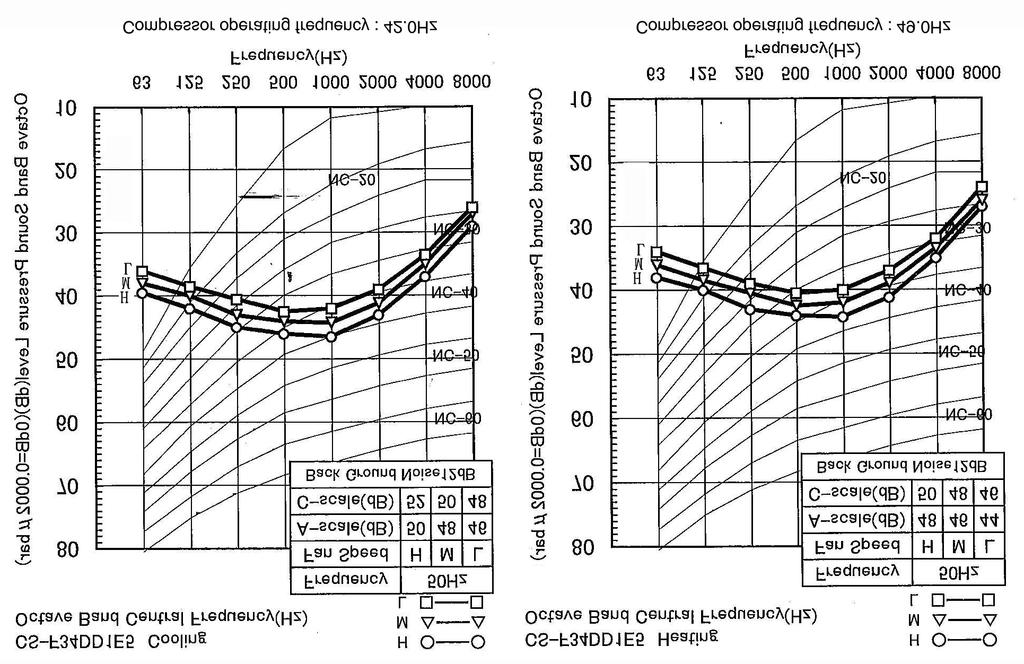
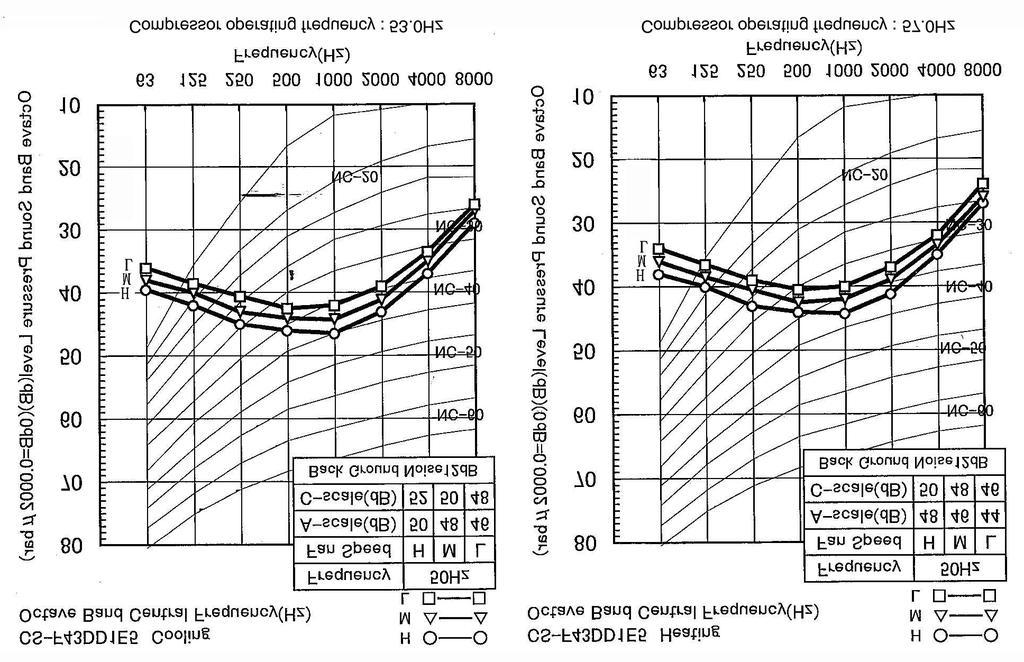
99 99
100 100
101 101
102 102
103 103
104 13.2. Sound measurement point Indoor unit Outdoor unit 104
105 13.3. Discharge and suction pressure Saturation temperature of discharge and suction pressure COOLING 105
106 HEATING 106


107 13.4. Capacity and power consumption Cooling performance CS-F24DD1E5 CU-B24DBE5 Model Cooling capacities are based on conditions CS-F24DD1E5 CU-B24DBE5 Single phase, 50Hz, 230V Cooling capacity Indoor temp. 27 C D.B. 19 C W.B. 6.6 kw Outdoor temp. 35 C D.B. Standard air volume 22 m 3 /min TC : Cooling Capacity SHC : Sensible Heat Capacity IPT : Cooling Power Consumption 107
108 108

109 CS-F28DD1E5 CU-B28DBE5 Model Cooling capacities are based on conditions CS-F28DD1E5 CU-B28DBE5 Single phase, 50Hz, 230V Cooling capacity Indoor temp. 27 C D.B. 19 C W.B. 7.3 kw Outdoor temp. 35 C D.B. Standard air volume 30 m 3 /min TC : Cooling Capacity SHC : Sensible Heat Capacity IPT : Cooling Power Consumption 109
110 110

111 CS-F28DD1E5 CU-B28DBE8 Model Cooling capacities are based on conditions CS-F28DD1E5 CU-B28DBE8 3 phase, 50Hz, 400V Cooling capacity Indoor temp. 27 C D.B. 19 C W.B. 7.3 kw Outdoor temp. 35 C D.B. Standard air volume 30 m 3 /min TC : Cooling Capacity SHC : Sensible Heat Capacity IPT : Cooling Power Consumption 111
112 112

113 CS-F34DD1E5 CU-B34DBE5 Model Cooling capacities are based on conditions CS-F34DD1E5 CU-B34DBE5 Single phase, 50Hz, 230V Cooling capacity Indoor temp. 27 C D.B. 19 C W.B. 10 kw Outdoor temp. 35 C D.B. Standard air volume 40 m 3 /min TC : Cooling Capacity SHC : Sensible Heat Capacity IPT : Cooling Power Consumption 113
114 114

115 CS-F34DD1E5 CU-B34DBE8 Model Cooling capacities are based on conditions CS-F34DD1E5 CU-B34DBE8 3 phase, 50Hz, 400V Cooling capacity Indoor temp. 27 C D.B. 19 C W.B. 10 kw Outdoor temp. 35 C D.B. Standard air volume 40 m 3 /min TC : Cooling Capacity SHC : Sensible Heat Capacity IPT : Cooling Power Consumption 115
116 116


117 CS-F43DD1E5 CU-B43DBE8 Model Cooling capacities are based on conditions CS-F43DD1E5 CU-B43DBE8 3 phase, 50Hz, 400V Cooling capacity Indoor temp. 27 C D.B. 19 C W.B kw Outdoor temp. 35 C D.B. Standard air volume 50 m 3 /min TC : Cooling Capacity SHC : Sensible Heat Capacity IPT : Cooling Power Consumption 117
118 118
119 CS-F50DD1E5 CU-B50DBE8 Model Cooling capacities are based on conditions CS-F50DD1E5 CU-B50DBE8 3 phase, 50Hz, 400V Cooling capacity Indoor temp. 27 C D.B. 19 C W.B kw Outdoor temp. 35 C D.B. Standard air volume 60 m 3 /min TC : Cooling Capacity SHC : Sensible Heat Capacity IPT : Cooling Power Consumption 119
120 120
121 Heating performance CS-F24DD1E5 CU-B24DBE5 Model Heating capacities are based on conditions CS-F24DD1E5 CU-B24DBE5 Single phase, 50Hz, 230V Heating capacity Indoor temp. 20 C D.B. 7.1 kw Outdoor temp. 7 C D.B. 6 C W.B. Standard air volume 22 m 3 /min CS-F28DD1E5 CU-B28DBE5 Model Heating capacities are based on conditions CS-F28DD1E5 CU-B28DBE5 Single phase, 50Hz, 230V Heating capacity Indoor temp. 20 C D.B. 8.0 kw Outdoor temp. 7 C D.B. 6 C W.B. Standard air volume 30 m 3 /min CS-F28DD1E5 CU-B28DBE8 Model Heating capacities are based on conditions CS-F28DD1E5 CU-B28DBE8 3 phase, 50Hz, 400V Heating capacity Indoor temp. 20 C D.B. 8.0 kw Outdoor temp. 7 C D.B. 6 C W.B. Standard air volume 30 m 3 /min 121

122 CS-F34DD1E5 CU-B34DBE5 Model Heating capacities are based on conditions CS-F34DD1E5 CU-B34DBE5 Single phase, 50Hz, 230V Heating capacity Indoor temp. 20 C D.B kw Outdoor temp. 7 C D.B. 6 C W.B. Standard air volume 40 m 3 /min CS-F34DD1E5 CU-B34DBE8 Model Heating capacities are based on conditions CS-F34DD1E5 CU-B34DBE8 3 phase, 50Hz, 400V Heating capacity Indoor temp. 20 C D.B kw Outdoor temp. 7 C D.B. 6 C W.B. Standard air volume 40 m 3 /min CS-F43DD1E5 CU-B43DBE8 Model Heating capacities are based on conditions CS-F43DD1E5 CU-B43DBE8 3 phase, 50Hz, 400V Heating capacity Indoor temp. 20 C D.B. 14 kw Outdoor temp. 7 C D.B. 6 C W.B. Standard air volume 50 m 3 /min 122
123 CS-F50DD1E5 CU-B50DBE8 Model Heating capacities are based on conditions CS-F50DD1E5 CU-B50DBE8 3 phase, 50Hz, 400V Heating capacity Indoor temp. 20 C D.B. 15 kw Outdoor temp. 7 C D.B. 6 C W.B. Standard air volume 60 m 3 /min 123
124 13.5. Fan performance CS-F24DD1E5 Fan performance test report Fan performance curve 124
125 CS-F28DD1E5 Fan performance test report Fan performance curve 125
126 CS-F34DD1E5 Fan performance test report Fan performance curve 126
127 CS-F43DD1E5 Fan performance test report Fan performance curve 127
128 CS-F50DD1E5 Fan performance test report Fan performance curve 128
129 13.6. Safety device Indoor unit Indoor unit Heat pump model CS-F24DD1E5 CS-F28DD1E5 CS-F34DD1E5 CS-F43DD1E5 CS-F50DD1E5 Cooling only model For fan motor protection Internal OFF C protector ON C For control protection Fuse CUT A For fan motor protection Fuse CUT A Outdoor unit Outdoor unit Heat pump 50Hz CU-B24DBE5 CU-B28DBE5 CU-B28DBE8 CU-B34DBE5 CU-B34DBE8 CU-B43DBE8 CU-B50DBE8 model For refrigerant cycle High pressure OFF MPa switch (63H1) ON MPa Low pressure switch OFF MPa ON MPa For compressor Over current protection Heat pump model OFF A Cooling only model OFF A RESET - Automatic Automatic Automatic Automatic Automatic Automatic Automatic Discharge temp protection Discharge Compressor temperature OFF C thermistor (Th1) Liquid compress protection Crankcase heater Input power W Compressor protection Internal protector OFF C Hz ON C Hz trip time 50Hz 3-10sec/65A 3-10sec/78A 3-10sec/26A For fan motor protection Internal OFF C protector (49F) ON C Heating control (Heat pump only) Pressure switch OFF MPa (Fan speed) (63H2) ON MPa Cooling control Heat exchanger Th 400 C High speed outlet temp Control method Th < 40 C 5 speed step control thermistor (Th2) For control protection Fuse CUT A MPa = 10.2kgf/cm 2 129

130 13.7. Operating characteristics S.C. : Starting Current R.C. : Running Current IPT : Power Consumption 130
131 14 REPLACEMENT PARTS Indoor unit CS-F24DD1E5, CS-F28DD1E5, CS-F34DD1E5, CS-F43DD1E5, CS-F50DD1E5 131
132 CS-F24DD1E5, CS-F28DD1E5, CS-F34DD1E5, CS-F43DD1E5, CS-F50DD1E5 REF. NO. PARTS NAME Q TY QUANTITY PER 1 UNIT CS-F24DD1E5 CS-F28DD1E5 CS-F34DD1E5 CS-F43DD1E5 CS-F50DD1E5 1 Cabinet (Bottom) 1 P02-T08080 P02-T08130 P02-T Cabinet (Bottom A) 1 P02-T08090 P02-T08140 P02-T Drain pan 1 P42-T03850 P42-T03920 P42-T Evaporator 1 P45-T07860 P45-T07870 P45-T Distributor as. 1 P45-T07750 P45-T07790 P45-T Cabinet (Top) 1 P02-T07570 P02-T Cabinet (Back) 1 P42-T03380 P42-T03400 P42-T Duct flange as.(outlet) 1 P42-T02390 P42-T02150 P42-T Fan base as. 1 P45-T07710 P45-T07720 P45-T07980 P45-T Casing as. 2 *P45-T07950 *P45-T07990 P45-T Impeller R P05-T Impeller L P05-T Fan motor 1 P06-T04910 P06-T04512 P06-T04920 P06-T Panel side R as. 1 P42-T03860 P42-T03880 P42-T Panel side L as. 1 P42-T03870 P42-T03890 P42-T Terminal board 1 P06-T Capacitor 1 P06-T04360 P06-T Transformer 1 A40C Remote control 1 A75C Thermistor as. 1 P46-T Coil sensor 1 P46-T PCB assembly (Programed) 1 P46-T06870 P46-T06890 P46-T07040 P46-T07050 P46-T FM Relay P06-T Fuse holder P06-T FM Fuse P06-T04740 *Casing included with impeller part. All parts are supplied from Taiwan (PTW). 132
133 14.2. Outdoor unit CU-B24DBE5, CU-B28DBE5, CU-B28DBE8 133
134 CU-B24DBE5, CU-B28DBE5, CU-B28DBE8 134
135 NO. PART DESCRIPTION QTY. CU-B24DBE5 CU-B28DBE5 CU-B28DBE8 1 BASE PAN ASSY 1 CWD52K COMPRESSOR 1 5JS315DAM21 5JS330DAF21 5JS330PBA21 3 ANTI-VIBRATION BUSHING 3 CWH NUT-COMPRESSOR MOUNT 3 CWH PACKING 3 CWB CRANKCASE HEATER 1 CWA CONDENSER COMPLETE 1 CWB32C1706 CWB32C TUBE ASSY (CAPILLARY TUBE) 1 CWT07K1306 CWT07K PIPE HOLDER RUBBER 1 CWG WAYS VALVE COMPLETE 1 CWB00C DISCHARGE MUFFLER 1 CWB WAYS VALVE 1 CWB001026J 13 HEATING PRESSURE SWITCH 1 CWA TUBE ASSY (STRAINER, EXP.VALVE) 1 CWT CWT WAYS VALVE (LIQUID) 1 CWB WAYS VALVE (GAS) 1 CWB STRAINER 1 CWB STRAINER 2 CWB PIPE HOLDER RUBBER 1 CWG HOLDER-SERVICE VALVE 1 CWD SOUND-PROOF BOARD 1 CWH TUBE RECEIVER 1 CWB14K1014A 23 SOUND PROOF MATERIAL 1 CWG V-COIL COMPLETE 1 CWA43C V-COIL COMPLETE 1 CWA43C2128J 26 PIPING SENSOR 1 CWA50C PIPING SENSOR 1 CWA50C SPRING FOR SENSOR 2 CWH CABINET REAR PLATE COMPLETE 1 CWE02C CONTROL BOARD ASSY 1 CWH10K1063 CWH10K TERMINAL BOARD ASSY 1 CWA28K1085J CWA28K TERMINAL BOARD ASSY 1 CWA28K1076J 33 CAPACITOR-FM (3.0µF/460V)(3.5µF/460V) 1 DS461305QP-A DS461355QP-A 34 CAPACITOR-COMP (45µF/370V)(50µF/370V) 1 DS371456CPNA DS371506CPNA - 35 HOLDER CAPACITOR 1 CWH ELECTRONIC CONTROLLER-MAIN 1 CWA73C1902 CWA73C1904 CWA73C MAGNETIC RELAY 1 K6C2A9A TRANSFORMER 1 CWA TERMINAL COVER 1 CWH CWH NUT FOR TERMINAL COVER 1 CWH J 41 BRACKET FAN MOTOR ASSY 1 CWD54K SCREW-FAN MOTOR BRACKET 2 CWH551040J 43 FAN MOTOR AC 70W SINGLE 1 CWA SCREW-FAN MOTOR BRACKET 4 CWH551040J 45 PROPELLER FAN 1 CWH NUT-PROPELLER FAN 1 CWH561038J 47 CABINET TOP PLATE COMPLETE 1 CWE03C PIPE COVER (FRONT) 1 CWD601074A 49 PIPE COVER (BACK) 1 CWD601081A 50 CABINET FRONT PLATE 1 CWE061118A 51 DISCHARGE GRILLE 1 CWE CABINET SIDE PLATE ASSY 1 CWE04K1019A 53 WIRE NET 1 CWD041063A 54 CABINET FRONT PLATE COMPLETE 1 CWE06C HANDLE 3 CWE LEADWIRE-COMPRESSOR 1 CWA67C5994 CWA67C WIRING COVER AND BAND 1 CWH82C INSTALLATION INSTRUCTION 1 CWF ACCESSORY COMP. (DRAIN ELBOW) 1 CWG87C ELECTRO MAGNETIC SWITCH K6C4E8A00003 All parts are supplied from PHAAM, Malaysia (Vendor Code: 061) 135
136 CU-B34DBE5, CU-B34DBE8, CU-B43DBE8, CU-B50DBE8 136
137 CU-B34DBE5, CU-B34DBE8, CU-B43DBE8, CU-B50DBE8 137
138 CU-B34DBE5, CU-B34DBE8, CU-B43DBE8, CU-B50DBE8 138
139 NO. PART DESCRIPTION QTY. CU-B34DBE5 CU-B34DBE8 CU-B43DBE8 CU-B50DBE8 1 BASE PAN ASSY 1 CWD52K COMPRESSOR 1 JT125G-P4V1 JT125G-P4Y1 JT160G-P4Y1 JT170G-P4Y1 3 ANTI-VIBRATION BUSHING 3 CWH NUT COMPRESSOR MOUNT 3 CWH CRANKCASE HEATER 1 CWA CONDENSER COMPLETE 1 CWB32C TUBE ASSY(CAPILLARY TUBE) 1 CWT07K WAYS VALVE COMPLETE 1 CWB00C1029 CWB00C1030 CWB00C WAYS VALVE 1 CWB DISCHARGE MUFFLER 1 CWB HEATING PRESSURE SWITCH 1 CWA WAYS VALVE (GAS) 1 CWB STRAINER 1 CWB PRESSURE SWITCH 1 CWA WAYS VALVE (LIQUID) 1 CWB TUBE ASSY(STRAINER, EXP.VALVE) 1 CWT RECEIVER ASSY 1 CWB14K1013A 18 SOUND PROOF MATERIAL 1 CWG SOUND PROOF MATERIAL 1 CWG V-COIL COMPLETE 1 CWA43C V-COIL COMPLETE 1 CWA43C2177J 22 HOLDER-SERVICE VALVE 1 CWD SOUND PROOF BOARD 1 CWH PIPING SENSOR 1 CWA50C PIPING SENSOR 1 CWA50C SPRING FOR SENSOR 2 CWH CABINET REAR PLATE COMPLETE 1 CWE02C CONTROL BOARD ASSY 1 CWH10K1063 CWH10K TERMINAL BOARD ASSY 1 CWA28K1085J CWA28K TERMINAL BOARD ASSY 1 CWA28K1076J 31 CAPACITOR-FM (3.0µF/460V)(3.5µF/460V) 2 DS461305QP-A DS461355QP-A 32 ELECTRO MAGNETIC SWITCH 1 K6C5E8A00001 CWA ELECTRONIC CONTROLLER-MAIN 1 CWA73C1906 CWA73C1907 CWA73C1908 CWA73C TRANSFORMER 1 CWA BRACKET FAN MOTOR ASSY 1 CWD54K SCREW-FAN MOTOR BRACKET 2 CWH551040J 37 FAN MOTOR AC 70W SINGLE 1 CWA FAN MOTOR AC 70W SINGLE 1 CWA SCREW-FAN MOTOR BRACKET 2 CWH551040J 40 PROPELLER FAN ASSY 2 CWH03K NUT-PROPELLER FAN 2 CWH561038J 42 CABINET TOP PLATE COMPLETE 1 CWE03C PIPE COVER (FRONT) 1 CWD601074A 44 PIPE COVER (BACK) 1 CWD60K1003A 45 CABINET FRONT PLATE 1 CWE061092A 46 DISCHARGE GRILLE 2 CWE CABINET SIDE PLATE ASSY 1 CWE04K1022A 48 WIRE NET 1 CWD041064A 49 CABINET FRONT PLATE COMPLETE 1 CWE06C HANDLE 2 CWE LEADWIRE-COMPRESSOR 1 CWA67C5903 CWA67C WIRING COVER AND BAND 1 CWH82C INSTALLATION INSTRUCTION 1 CWF ACCESSORY COMP. (DRAIN ELBOW) 1 CWG87C CAPACITOR-COMP. (35µF/440V) 2 DS441356CPNE HOLDER CAPACITOR 2 CWH All parts are supplied from PHAAM, Malaysia (Vendor Code: 061) 139

140 15 PRINT PATTERN Indoor unit INDOOR UNIT PRINTED CIRCUIT BOARD (MAIN) 140
 141 [PHAAM] Printed in Malaysia")
141 15.2. Outdoor unit OUTDOOR UNIT PRINTED CIRCUIT BOARD (MAIN) 141 [PHAAM] Printed in Malaysia SFYW
CU-B24DBE5 CS-F28DTE5 CU-B28DBE5 CS-F28DTE5 CU-B28DBE8 CS-F34DTE5 CU-B34DBE5 CS-F34DTE5 CU- B34DBE8 CS-F43DTE5 CU-B43DBE8 CS-F50DTE5 CU-B50DBE8,
 Order No. MAC0605029C2 Air Conditioner CS-F18DTE5 CU-B34DBE5 CS-F18DTE5 CU-B34DBE8 CS-F24DTE5 CU-B43DBE8 CS-F28DTE5 CU-B50DBE8 Please file and use this manual together with the service manual for Model
TABLE OF CONTENTS. Air Conditioner CS-F18DTE5 CU-J18DBE5
 Order No. MAC0602019C2 Air Conditioner CS-F18DTE5 CU-J18DBE5 TABLE OF CONTENTS PAGE 1 Service Information---------------------------------------------- 3 1.1. Example of trouble at test operation------------------
Room Air Conditioner CONTENTS CS-E9BKP CU-E9BKP5 CS-E12BKP CU-E12BKP5. Order No: MAC C2
 Order No: MAC008C Room Air Conditioner CS-E9BKP CU-E9BKP5 CS-EBKP CU-EBKP5 CONTENTS Page Page Features Functions Product Specifications 6 Dimensions 0 5 Refrigeration Cycle Diagram 6 Block Diagram 7 Wiring
Energy-saving operation
 DC Inverter can attain both comfort a Energy-saving operation All the models of Panasonic FS Inverter Series are equipped with DC inverters for the higher EER operation. The new design attains quiet and
Air Conditioner CONTENTS CS-E18EKU CU-E18EKU CS-E21EKU CU-E21EKU. Order No: MAC C1
 Order No: MAC0512115C1 CS-E18EKU CU-E18EKU CS-E21EKU CU-E21EKU Air Conditioner CONTENTS Page Page 1 Safety Precautions 3 2 Specification 5 2.1. CS-E18EKU CU-E18EKU 5 2.2. CS-E21EKU CU-E21EKU 7 3 Location
SERVICE MANUAL MUY-GL24NA - U1. No. OBH733. Models HFC. Revision B: REVISED EDITION-B R410A
 Revision B: MUZ-GL09NA- U8 and MUZ-GL09NAH- U8 have been added. Please void OBH733 REVISED EDITION-A. OUTDOOR INDOOR UNIT UNIT SERVICE MANUAL HFC utilized R410A. OBH733 REVISED EDITION-B Models MUZ-GL09NA
TABLE OF CONTENTS. Air Conditioner CS-NE7GKE CU-NE7GKE CS-NE9GKE CU-NE9GKE CS-NE12GKE CU-NE12GKE
 Order No. MAC0705021C2 Air Conditioner CS-NE7GKE CU-NE7GKE CS-NE9GKE CU-NE9GKE CS-NE12GKE CU-NE12GKE TABLE OF CONTENTS PAGE 1 Safety Precaution ------------------------------------------------ 2 2 Specifications
AUTO COOL DRY FAN SPEED AIR SWING OFF ON TIMER TIMER OFF/ON FAN SPEED MODE TEMP AIR SWING TIMER ON SET OFF CANCEL AC RC SET CHECK CLOCK RESET
 AUTO COOL DRY MODE TIMER ON OFF TIMER OFF/ON TEMP ON TIMER FAN SPEED AIR SWING SET 1 2 3 FAN SPEED AIR SWING OFF CANCEL AC RC SET CHECK CLOCK RESET Order No: PAPAMY1611008CE Indoor Unit CS-MPS9SKH CS-MPS12SKH
SERVICE MANUAL. No. OBH747 REVISED EDITION-A. Models HFC
 Revision A: MUZ-HM09/12NA- U8, MUZ-HM09/12NA2- U8, MUZ-HM15/18NA- U1, MUZ-HM15/18NA2- U1 and MUZ-HM24NA2- U1 have been added. Please void OBH747. OUTDOOR INDOOR UNIT UNIT SERVICE MANUAL HFC utilized R410A.
Air Conditioner CONTENTS CS-E9DKEW CU-E9DKE CS-E12DKEW CU-E12DKE. Order No: MAC C2
 Order No: MAC041064C CS-E9DKEW CU-E9DKE CS-E1DKEW CU-E1DKE Air Conditioner CONTENTS Page Page 1 Features Functions 3.1. Remote Control 3.. Indoor Unit 4.3. Outdoor Unit 6 3 Product Specifications 7 3.1.
TABLE OF CONTENTS. Air Conditioner CS-E24GKES CU-E24GKE CS-E28GKE CU-E28GKE
 Order No. MAC0701008C2 CS-E24GKES CU-E24GKE CS-E28GKE CU-E28GKE Air Conditioner TABLE OF CONTENTS PAGE 1 Safety Precautions----------------------------------------------- 2 2 Specifications -----------------------------------------------------
SERVICE MANUAL OUTDOOR UNIT MUZ-FH06NAH MUZ-FH09NAH MUZ-FH06NA MUZ-FH09NA MUZ-FH09NA - 1 MUZ-FH09NAH - 1 MUZ-FH12NA MUZ-FH12NAH
 Revision D: Capacity corrections have been corrected [7-1. 2), 3)]. OBH684 REVISED EDITION-C is void. OUTDOOR UNIT SERVICE MANUAL HFC utilized R410A. OBH684 REVISED EDITION-D Models MUZ-FH06NA MUZ-FH09NA
DC INVERTER MULTI-SYSTEM AIR CONDITIONER
 TECHNICAL & SERVICE MANUAL OUTDOOR UNIT : CU-3KE19NBU CU-4KE24NBU CU-4KE31NBU DC INVERTER MULTI-SYSTEM AIR CONDITIONER Capacity at 0V 19,100 BTU/h,200 BTU/h 30,600 BTU/h Outdoor Model No. CU-3KE19NBU CU-4KE24NBU
DESIGN & TECHNICAL MANUAL
 AIR CONDITIONER Wall mounted type DESIGN & TECHNICAL MANUAL For Extra Cold Climate Area INDOOR ASU18RLF ASU24RLF OUTDOOR AOU18RLXFWH AOU24RLXFWH DR_AS014EF_04 2017.03.10 Notices: Product specifications
TABLE OF CONTENTS. Air Conditioner CS-MRE12MKE
 Order No. PHAAM1103074C8 Indoor Unit CS-MRE7MKE CS-MRE9MKE CS-MRE12MKE Air Conditioner Outdoor Unit CU-2RE15MBE CU-2RE18MBE TABLE OF CONTENTS PAGE 1 Safety Precautions-----------------------------------------------
CS-E18NKUA CS-E24NKUA CU-E18NKUA CU-E24NKUA TABLE OF CONTENTS WARNING
 Order No: PAPAMY1204088CE Indoor Unit CS-E18NKUA CS-E24NKUA Outdoor Unit CU-E18NKUA CU-E24NKUA WARNING This service information is designed for experienced repair technicians only and is not designed for
CU-3E23CBPG, CU- 4E27CBPG,
 Order No. PHAAM0810051C2 Air Conditioner Indoor Unit Outdoor Unit CS-E7JKEW CU-E7JKE CS-E9JKEW CU-E9JKE CS-E12JKEW CU-E12JKE CS-E15JKEW CU-E15JKE CS-E15JKEW CU-E15JKE-1 CS-E7JKEW-3 CU-E7JKE-3 CS-E9JKEW-3
Room Air Conditioner CONTENTS CS-E18CKE CU-E18CKE CS-E21CKE CU-E21CKE. Order No. MAC C2
 Order No. MAC00801C Room Air Conditioner CS-E18CKE CU-E18CKE CS-E1CKE CU-E1CKE CONTENTS Page Page 1 Features Functions Product Specifications 6 4 Dimensions 10 5 Refrigeration Cycle Diagram 1 6 Block Diagram
Air-to-Water Hydromodule + Tank WH-UX12FE5 WH-UD12FE5 WH-UD16FE5. Destination Europe WARNING
 Order : PAPAMY420CE Air-to-Water Hydromodule + Tank Indoor Unit WH-ADC26G6E5 Outdoor Unit WH-UX09FE5 WH-UX2FE5 WH-UD2FE5 WH-UD6FE5 Destination Europe WARNING This service information is designed for experienced
DESIGN & TECHNICAL MANUAL
 AIR CONDITIONER Wall mounted type DESIGN & TECHNICAL MANUAL INDOOR ASYG18KLCA ASYG24KLCA OUTDOOR AOYG18KLTA AOYG24KLTA DR_AS069EF_01 2018.03.16 Notices: Product specifications and design are subject to
SERVICE MANUAL MUZ-FH25VE MUZ-FH35VE MUZ-FH50VE OUTDOOR UNIT. No. OBH624. Models HFC. Revision A: MUZ-FH50VE- E1 has been added. Please void OBH624.
 SPLIT-TYPE AIR CONDITIONERS Revision A: MUZ-FH50VE- E1 has been added. Please void OBH624. OUTDOOR UNIT SERVICE MANUAL HFC utilized R410A. OBH624 REVISED EDITION-A Models MUZ-FH25VE MUZ-FH35VE MUZ-FH50VE
CS-XE9EKE CU-XE9EKE CS-XE12EKE CU-XE12EKE
 Order No. MAC0512111C8 Air Conditioner CS-XE9EKE CU-XE9EKE CS-XE12EKE CU-XE12EKE TABLE OF CONTENTS PAGE 1 Safety Precautions----------------------------------------------- 3 2 Specifications -----------------------------------------------------
6. DUCT TYPE AR 60FUAK, AR 60UUAK
 R410A 6. AR 60FUAK, AR 60UUAK ART60UUAK D2D_AR010E/04 2006.05.30 - (06-01) - 6-1. FEATURE MODELS : AR 60FUAK / AO 60FMAYT AR 60UUAK / AO 60UMAYT ART60UUAK / AOT60UMAYT FEATURES Universal design indoor
TABLE OF CONTENTS. Air Conditioner. Indoor Unit Outdoor Unit CS-NE9LKE CU-NE9LKE CS-NE12LKE CU-NE12LKE CS-XE9LKE-5 CU-NE9LKE CS-XE12LKE-5 CU-NE12LKE
 Order No. PHAAM1007139C2 Air Conditioner Indoor Unit Outdoor Unit CS-NE9LKE CU-NE9LKE CS-NE12LKE CU-NE12LKE CS-XE9LKE-5 CU-NE9LKE CS-XE12LKE-5 CU-NE12LKE TABLE OF CONTENTS PAGE 1 Safety Precautions-----------------------------------------------
Hi - Wall Split Systems. Super Quiet. Auto. Mode. Wireless Control. Smart Airflow ECO ECO. Function SLEEP. Vertical Auto Swing.
 R407C 220-240V ~, 50Hz Hi - Wall Split Systems Technology Tropical Compressor Super Quiet Auto Mode Auto Restart Easy Flexible Installation IAQ Anti-dust Filters AMS AMS Wireless Control Independent Dehumidification
DESIGN & TECHNICAL MANUAL
 AIR CONDITIONER Wall mounted type DESIGN & TECHNICAL MANUAL INDOOR ASYG07KGTA ASYG09KGTA ASYG12KGTA ASYG14KGTA OUTDOOR AOYG07KGCA AOYG09KGCA AOYG12KGCA AOYG14KGCA DR_AS049EF_02 2017.10.11 Notices: Product
V ~, 50Hz 1Ph. High Wall Split Systems Heat Pump 9K - 12K - 18K - 24K - 28K. Auto. Auto Fan Speed. Auto. Smart LCD Wireless Control.
 HFC4 1 0 A 0-40V ~, 0Hz 1Ph High Wall Split Systems Heat Pump 9K - 1K - 18K - 4K - 8K R-410A Compressor Super Quiet AMS Anti-dust Filters Auto Fan Speed Timer Functions Defrost Protection Smart LCD Wireless
Hi - Wall Split Systems 12K - 18K - 24K
 R22 220-240V ~ 50Hz 1Ph Hi - Wall Split Systems 12K - 18K - 24K Technology Tropical Compressor Super Quiet Auto Auto Fan Speed Auto Restart Function Self diagnostic function Active Carbon Electrostatic
High Wall Split Systems Cool Only 9K - 12K - 18K - 24K. Auto. Auto. Fan Speed. Smart LCD Wireless Control. Auto Mode.
 HFC4 1 0 A 0-40V ~, 0Hz 1Ph High Wall Split Systems Cool Only 9K - 1K - 18K - 4K R-410A IAQ $ Auto Auto Fan Speed Timer s Easy Flexible Installation Smart LCD Wireless Control Auto Mode Auto Restart Easy
DESIGN & TECHNICAL MANUAL
 AIR CONDITIONER Duct type DESIGN & TECHNICAL MANUAL INDOOR ARU9RLF ARU12RLF ARU18RLF OUTDOOR AOU9RLFC AOU12RLFC AOU18RLFC 1. INDOOR UNIT : ARU9RLF ARU12RLF ARU18RLF DTR_AR059E_05 2015.06.01 1. INDOOR UNIT
CS-RE9JKX-1 CS-RE12JKX-1 CS-RE15JKX-1 CU-RE9JKX-1 CU-RE12JKX-1 CU-RE15JKX-1 TABLE OF CONTENTS WARNING
 Order No: PHA-AG1002007C2 Indoor Unit CS-RE9JKX-1 CS-RE12JKX-1 CS-RE15JKX-1 Outdoor Unit CU-RE9JKX-1 CU-RE12JKX-1 CU-RE15JKX-1 WARNING This service information is designed for experienced repair technicians
CU-YE9MKE CU-YE12MKE CU-YE18MKE CS-YE9MKE CS-YE12MKE CS-YE18MKE TABLE OF CONTENTS WARNING
 Order No: PHA-AG1102003C2 Indoor Unit CS-YE9MKE CS-YE12MKE CS-YE18MKE Outdoor Unit CU-YE9MKE CU-YE12MKE CU-YE18MKE WARNING This service information is designed for experienced repair technicians only and
Air Conditioner CONTENTS CS-V18DKE CU-V18DKE CS-V24DKE CU-V24DKE. Order No. MAC C2
 Order No. MAC0410044C2 CS-V18DKE CU-V18DKE CS-V24DKE CU-V24DKE Air Conditioner CONTENTS Page Page 1 Features 2 2 Functions 3 2.1. Remote Control 3 2.2. Indoor Unit 4 2.3. Outdoor Unit 5 3 Product Specifications
SERVICE MANUAL MUFZ-KJ50VE - E1, E2, ER1, ER2, ET1, ET2 MUFZ-KJ35VE OUTDOOR UNIT. No. OBH667. Models HFC
 Revision D: MUFZ-KJ25VE - E2, ER2, ET2, MUFZ- KJ35VE - E2, ER2, ET2 and MUFZ- KJ50VE - E2, ER2, ET2 have been added. Please void OBH667 REVISED EDITION-C. OUTDOOR UNIT SERVICE MANUAL HFC utilized R410A.
TAC-09CS/K TAC-12CS/K TAC-18CS/K TAC-24CS/K TAC-07CHS/K TAC-09CHS/K TAC-12CHS/K TAC-18CHS/K TAC-24CHS/K
 TCL WALL MOUNTED SPLIT-TYPE AIR CONDITIONERS SERVICE MANUAL No.TE040427 Models TAC-07CS/K TAC-09CS/K TAC-2CS/K TAC-8CS/K TAC-24CS/K TAC-07CHS/K TAC-09CHS/K TAC-2CHS/K TAC-8CHS/K TAC-24CHS/K CONTENTS. IMPORTANT
SERVICE MANUAL MSZ-GL06NA - U1 MSZ-GL09NA - U1 MSZ-GL12NA - U1 MSZ-GL15NA - U1 MSZ-GL18NA - U1 MSZ-GL24NA - U1
 Revision B: 3. SPECIFICATION has been corrected. Please void OBH732 REVISED EDITION-A. INDOOR UNIT SERVICE MANUAL. OBH732 REVISED EDITION-B Models MSZ-GL06NA - U1 MSZ-GL09NA - U1 MSZ-GL12NA - U1 MSZ-GL15NA
SERVICE INSTRUCTION R410A. SPLIT TYPE ROOM AIR CONDITIONER Cassette type Duct type Ceiling type INVERTER AO* G45LETL AO* G54LETL
 SPLIT TYPE ROOM AIR CONDITIONER Cassette type Duct type Ceiling type INVERTER SERVICE INSTRUCTION Models Indoor unit AU* G45LRLA AR* G45LMLA AR* G45LHTA AB* G45LRTA Outdoor unit AO* G45LETL AO* G54LETL
DESIGN & TECHNICAL MANUAL
 AIR CONDITIONER Wall Mounted type DESIGN & TECHNICAL MANUAL INDOOR ASU9RL2 ASU12RL2 OUTDOOR AOU9RL2 AOU12RL2 1.INDOOR UNIT : ASU9RL2 ASU12RL2 DTR_AS072E_01 2012.11.02 1. INDOOR UNIT CONTENTS 1. FEATURE...
DC INVERTER SPLIT SYSTEM AIR CONDITIONER
 AIR CONDITIONER TECHNICAL & SERVICE MANUAL KS1872 + C1872 + CL1872 KS2472 + C2472 + CL2472 FILE NO. Destination: North America DC INVERTER SPLIT SYSTEM AIR CONDITIONER Indoor Model No. KS1872 KS2472 Product
DESIGN & TECHNICAL MANUAL
 AIR CONDITIONER Wall mounted type DESIGN & TECHNICAL MANUAL INDOOR ASYG07LMCE ASYG09LMCE ASYG12LMCE ASYG14LMCE OUTDOOR AOYG07LMCE AOYG09LMCE AOYG12LMCE AOYG14LMCE DR_AS037EF_01 2016.12.05 Notices: Product
R410A. AIR CONDITIONER DUCT TYPE / ART Series OPERATING MANUAL. REFRIGERANT This Air Conditioner contains and operates with refrigerant R410A.
 AIR CONDITIONER DUCT TYPE / ART Series OPERATING MANUAL KEEP THIS OPERATION MANUAL FOR FUTURE REFERENCE R410A REFRIGERANT This Air Conditioner contains and operates with refrigerant R410A. THIS PRODUCT
Air-to-Water Hydromodule + Tank WH-UD05HE5-1 WH-UD07HE5-1 WH-UD09HE5-1. Destination Europe Turkey
 Order : PAPAMY1607068CE Air-to-Water Hydromodule + Tank Indoor Unit WH-ADC0309H3E5 Outdoor Unit WH-UD03HE5-1 WH-UD05HE5-1 WH-UD07HE5-1 WH-UD09HE5-1 Destination Europe Turkey WARNING This service information
OWNER S MANUAL. R 410A Ductless Split System Air Conditioner and Heat Pump
 R 410A Ductless Split System Air Conditioner and Heat Pump Models DLC4(A/H) Outdoor Unit, DLF4(A/H) Indoor Unit Sizes 9K, 12K, 18K, 24K, 30K and 36K Please read the operating instructions and safety precautions
DESIGN & TECHNICAL MANUAL
 AIR CONDITIONER Duct type DESIGN & TECHNICAL MANUAL INDOOR ARU9RLF ARU12RLF ARU18RLF OUTDOOR AOU9RLFC AOU12RLFC AOU18RLFC 1. INDOOR UNIT : ARU9RLF ARU12RLF ARU18RLF DTR_AR059E_01 2013.02.28 1. INDOOR UNIT
CU-S9NKV-7 CU-S12NKV-7 CU-S18NKV-7 CU-S22NKV-7 CS-S9NKV-7 CS-S12NKV-7 CS-S18NKV-7 CS-S22NKV-7 WARNING
 Order No: PAPAMY1206010CE Indoor Unit CS-S9NKV-7 CS-S12NKV-7 CS-S18NKV-7 CS-S22NKV-7 Outdoor Unit CU-S9NKV-7 CU-S12NKV-7 CU-S18NKV-7 CU-S22NKV-7 WARNING This service information is designed for experienced
INVERTER WALL MOUNTED TYPE ROOM AIR-CONDITIONER (Split system, air to air heat pump type)
") TECHNICAL MANUAL & PARTS LIST DRAFT INVERTER WALL MOUNTED TYPE ROOM AIR-CONDITIONER (Split system, air to air heat pump type) SRK20ZD-S - 1 - INDOOR UNIT Model SRK20ZD-S OUTDOOR UNIT Model SRC20ZD-S REMOTE
TECHNICAL MANUAL & PARTS LIST DRAFT INVERTER WALL MOUNTED TYPE ROOM AIR-CONDITIONER (Split system, air to air heat pump type) SRK20ZD-S - 1 - INDOOR UNIT Model SRK20ZD-S OUTDOOR UNIT Model SRC20ZD-S REMOTE
OPERATING MANUAL AIR CONDITIONER DUCT TYPE. ART Series KEEP THIS MANUAL FOR FUTURE REFERENCE FUJITSU GENERAL LIMITED P/N
 OPERATING MANUAL AIR CONDITIONER DUCT TYPE ART Series KEEP THIS MANUAL FOR FUTURE REFERENCE FUJITSU GENERAL LIMITED P/N9374379293-02 CONTENTS SAFETY PRECAUTIONS... 1 NAME OF PARTS... 2 PREPARATORY OPERATION...
Slim Line Ceiling Concealed Ducted Split Systems. Medium Static Pressure. Ducted Split System Heat Pump
 0-40V ~ 0Hz Ph 80-40V ~ 0Hz Ph Slim Line Ceiling Concealed Ducted Split Systems Green Medium Static Pressure Ducted Split System Heat Pump - 8-4 - 0 - - 48-0 DC Inverter Inverter Technology $ Efficient
CS-UE9PKE CS-UE12PKE CU-UE9PKE CU-UE12PKE TABLE OF CONTENTS WARNING
 Order No: PAPAGZ121215CE Indoor Unit CS-UE9PKE CS-UE12PKE Outdoor Unit CU-UE9PKE CU-UE12PKE WARNING This service information is designed for experienced repair technicians only and is not designed for
SERVICE MANUAL ROOM AIR CONDITIONER TAN/TAG-A28FWIS TAN/TAG-A32FWIS CONTENTS
 SERVICE MANUAL ROOM AIR CONDITIONER TAN/TAG-A28FWIS TAN/TAG-A32FWIS CONTENTS SPECIFICATION... 1 FUNCTIONS... 5 SERVICE FUNCTION EXPLANATION... 7 OPERATION DETAILS... 8 TROUBLESHOOTING GUIDE... 13 PERFORMANCE
SRK20ZFX-S, 25ZFX-S, 35ZFX-S, 50ZFX-S
 Manual No. 06. SRK-T. 051 TECHNICAL MANUAL Collection data INVERTER WALL MOUNTED TYPE ROOM AIR-CDITIER ( Split system, air to air heat pump type ) SRK20ZFX-S, 25ZFX-S, 35ZFX-S, 50ZFX-S CTENTS 1. GENERAL
Кондиционеры Mitsubishi Heavy
 Кондиционеры Mitsubishi Heavy Техническое руководство Кондиционеры настенного типа SRK28HD, SRK40HD INDOOR UNIT Models SRK28HD, SRK40HD OUTDOOR UNIT Model SRC28HD REMOTE CONTROLLER Model SRC40HD GENERAL
OPERATING MANUAL. AIR CONDITIONER Duct Type. Indoor Unit ARTG36LH ARTG45LH ARTG54LH ARTG60LH PART NO KEEP THIS MANUAL FOR FUTURE REFERENCE
 OPERATING MANUAL AIR CONDITIONER Duct Type Indoor Unit ARTG36LH ARTG45LH ARTG54LH ARTG60LH KEEP THIS MANUAL FOR FUTURE REFERENCE PART NO. 9374379583 CONTENTS SAFETY PRECAUTIONS... 2 FEATURES AND FUNCTIONS...
DC INVERTER MULTI-SYSTEM AIR CONDITIONER
 TECHNICAL & SERVICE MANUAL OUTDOOR UNIT : CLM97 CLM7 CLM7 FILE NO. Destination: North America DC INVERTER MULTI-SYSTEM AIR CONDITIONER Capacity at 0V 9,700 BTU/h,00 BTU/h 0,600 BTU/h Outdoor Model No.
15A 18-2 AWG / 300V THHN Cooling (Max) 118 F (48 C)
 118 F (48 C)") Innovative Ductless Mini Split Solution Job Name Location Date Purchaser Engineer Submitted To For Unit Designation Schedule No. GENERAL FEATURES -Multi-Speed Fan -Medium Static Pressure Capability -Return
Innovative Ductless Mini Split Solution Job Name Location Date Purchaser Engineer Submitted To For Unit Designation Schedule No. GENERAL FEATURES -Multi-Speed Fan -Medium Static Pressure Capability -Return
1. WALL MOUNTED TYPE ROOM AIR-CONDITIONER Split system, Air to air heat pump type
 1. WALL MOUNTED TYPE ROOM AIR-CONDITIONER Split system, Air to air heat pump type ( ) SRK25GZ-L1, SRK35GZ-L1, SRK502Z-L 1 CONTENTS 1.1 GENERAL INFORMATION... 3 1.1.1 Specific features... 3 1.1.2 How to
AIR CONDITIONING REVERSE-CYCLE INVERTER
 AIR CONDITIONING REVERSE-CYCLE INVERTER CLASS LEADING FEATURES FASTER COOLING The new Panasonic Thermal Enhancement Technology (P-TECh) enables the compressor to achieve maximum frequency in the shortest
DESIGN & TECHNICAL MANUAL
 AIR CONDITIONER Duct type DESIGN & TECHNICAL MANUAL INDOOR AR GLLTB AR G4LLTB AR G8LLTB OUTDOOR AO GLALL AO G4LALL AO G8LALL . INDOOR UNIT : AR GLLTB AR G4LLTB AR G8LLTB DTR_AR54E_ 3..8 . INDOOR UNIT CONTENTS.
2 &3-4 Head Multi System
 2 &3-4 Head Multi System INVERTER 2 &3-4 ROOM Multi System The Fujitsu Inverter Multi System has been designed with flexibility in mind. With the introduction of indoor units in a range of capacities and
DUCTED AIR CONDITIONER RANGE YOUR COMFORT ZONE.
 DUCTED AIR CONDITIONER RANGE YOUR COMFORT ZONE. Kaden Ducted Air Conditioners Creating the ideal climate in different rooms throughout your home is essential for your family s comfort. Whether it s a
WH-UD03HE5 WH-UD05HE5 WH-SDC03H3E5 WH-SDC05H3E5. Destination Europe Turkey WARNING
 Order No: PAPAMY1509111CE Indoor Unit WH-SDC03H3E5 WH-SDC05H3E5 Outdoor Unit WH-UD03HE5 WH-UD05HE5 Destination Europe Turkey WARNING This service information is designed for experienced repair technicians
Miraco MISR REFRIGERATION & AIR CONDITIONING MFG. CO.
 MISR REFRIGERATION & AIR CONDITIONING MFG. CO. COOL EER HEAT COP 0V ~ 50Hz 1Ph Inverter High Wall Split Systems For Energy Saving Heat Pump 1K - 18K - 4K DC Inverter R-410A Inverter Technology R-410A HFC
DESIGN & TECHNICAL MANUAL
 AIR CONDITIONER Wall Mounted type DESIGN & TECHNICAL MANUAL INDOOR AS A09LEC AS A12LEC OUTDOOR AO R09LECN AO R12LECN 1.INDOOR UNIT : AS A09LEC AS A12LEC DTR_AS047E_01 2010.10.05 1. INDOOR UNIT CONTENTS
(Non-Inverter & Inverter) R410A
 R410A") LG Commercial Air Conditioner Sinlge Split Type (Non-Inverter & Inverter) R410A Distributed by LG Electronics www.lg.com http://partner.lge.com Copyright 2015 LG Electronics. All rights reserved. Non-Inverter
LG Commercial Air Conditioner Sinlge Split Type (Non-Inverter & Inverter) R410A Distributed by LG Electronics www.lg.com http://partner.lge.com Copyright 2015 LG Electronics. All rights reserved. Non-Inverter
DESIGN & TECHNICAL MANUAL
 AIR CONDITIONER Wall Mounted type DESIGN & TECHNICAL MANUAL INDOOR AS G07LLCC AS G09LLCC AS G12LLCC OUTDOOR AO G07LLCC AO G09LLCC AO G12LLCC 1.INDOOR UNIT : AS G07LLCC AS G09LLCC AS G12LLCC DTR_AS087E_02
Pure Efficiency Meets Healthy Living NEW 2013
 Pure Efficiency Meets Healthy Living NEW 2013 MILD DRY AUTOCOMFORT NEW 2013 nano technology cleaner perfect humidity control s improved comfort 20 db * *May apply to certain models only KIT PAN-XE9N PAN-XE12N
Heat Pump Air Conditioning Systems
 Heat Pump Air Conditioning Systems Create your own Utopia. In a climate as diverse as ours air conditioning your premises can make a huge difference to the comfort of your staff, and your customers too.
CONTENTS SAFETY PRECAUTIONS. En-1 DANGER! CAUTION!
 CONTENTS SAFETY PRECAUTIONS... 1 NAME OF PARTS... 2 PREPARATORY OPERATION... 3 OPERATION... 3 TIMER FUNCTIONS... 5 ON/OFF TIMER... 5 WEEKLY TIMER... 6 TEMPERATURE SET BACK TIMER... 8 FILTER DISPLAY RESET...
WALL MOUNTED AIR CONDITIONER RANGE THE PERFECT CLIMATE.
 WALL MOUNTED AIR CONDITIONER RANGE THE PERFECT CLIMATE. 02 - The Perfect Climate Kaden Wall Mounted Air Conditioners Creating the perfect climate in your home is essential for your family s comfort. Kaden
DC INVERTER SPLIT SYSTEM AIR CONDITIONER
 AIR CONDITIONER TECHNICAL & SERVICE MANUAL CS-KE30NKU + CU-KE30NKU CS-KE36NKU + CU-KE36NKU DC INVERTER SPLIT SYSTEM AIR CONDITIONER Indoor Model No. CS-KE30NKU CS-KE36NKU Product Code No. 1 852 360 88
AIR CONDITIONING AGAIN, AGAIN & AGAIN ONLY PANASONIC GETS 5 STARS #AIRTHATMOVESYOU
 ONLY PANASONIC GETS 5 STARS AGAIN, AGAIN & AGAIN AIR CONDITIONING AERO SERIES REVERSE-CYCLE INVERTER Reliability Functionality Ease of use Value for money After sales service Overall customer satisfaction.
TABLE OF CONTENTS. Air Conditioner
 Order No. MAC0804027A2 Air Conditioner CS-E9GFEW-2 CU-E9GFE-2 CS-E12GFEW-2 CU-E12GFE-2 CS-E18GFEW-2 CU-E18GFE-2 CU-2E15GBE CU-3E18EBE CU-3E23CBPG CU-4E27CBPG Please file and use this manual together with
SERVICE MANUAL MUZ-DM25VA - E1, ER1, ET1 MUZ-DM35VA - E1, ER1, ET1 OUTDOOR UNIT. No. OBH751. Models HFC R410A
 OUTDOOR UNIT SERVICE MANUAL HFC utilized R410A. Models MUZ-DM25VA - E1, ER1, ET1 MUZ-DM35VA - E1, ER1, ET1 Indoor unit service manual MSZ-DM VA Series (OBH750) CONTENTS 1. TECHNICAL CHANGES 2 2. PART NAMES
Power Input (Max) 1,500 W Dehumidification 1.7 pt/hr HSPF 10.5 COP 4.2 Compressor Type DC Inverter Driven 2-Stage Rotary Heating at 17 F FLA 8.
 1,500 W Dehumidification 1.7 pt/hr HSPF 10.5 COP 4.2 Compressor Type DC Inverter Driven 2-Stage Rotary Heating at 17 F FLA 8.") Submittal Data: CROWN09HP230V1B Superior Performance in Extreme Temperature 9,000 BTU/H Wall Mounted Heat- Pump System Job Name Location Date Purchaser Engineer Submitted To For Unit Designation Schedule
Submittal Data: CROWN09HP230V1B Superior Performance in Extreme Temperature 9,000 BTU/H Wall Mounted Heat- Pump System Job Name Location Date Purchaser Engineer Submitted To For Unit Designation Schedule
DESIGN & TECHNICAL MANUAL
 AIR CONDITIONER Duct type DESIGN & TECHNICAL MANUAL INDOOR AR G24LMLA OUTDOOR AO G24LALA 1. INDOOR UNIT : DTR_AR063E_01 2013.02.28 - (3) - 1. INDOOR UNIT CONTENTS 1. FEATURES... 01-01 2. WIRED REMOTE CONTROLLER...
INVERTER WALL MOUNTED TYPE ROOM AIR-CONDITIONER ( Split system, air to air heat pump type )
") Manual No. 06. SRK-T. 060 INVERTER WALL MOUNTED TYPE ROOM AIR-CONDITIONER ( Split system, air to air heat pump type ) SRK20ZG-S, SRK25ZG-S, SRK35ZG-S, SRK50ZG-S CONTENTS 1 GENERAL INFORMATION... 1 1.1
Manual No. 06. SRK-T. 060 INVERTER WALL MOUNTED TYPE ROOM AIR-CONDITIONER ( Split system, air to air heat pump type ) SRK20ZG-S, SRK25ZG-S, SRK35ZG-S, SRK50ZG-S CONTENTS 1 GENERAL INFORMATION... 1 1.1
DESIGN & TECHNICAL MANUAL
 AIR CONDITIONER Wall Mounted type DESIGN & TECHNICAL MANUAL INDOOR AS G07LMCA AS G09LMCA AS G12LMCA AS G14LMCA OUTDOOR AO G07LMCA AO G09LMCA AO G12LMCA AO G14LMCA 1. INDOOR UNIT : AS G07LMCA AS G09LMCA
SERVICE MANUAL MUZ-D30NA / - MUZ-D36NA / - MUY-D30NA / - MUY-D36NA / - OUTDOOR UNIT. No. OBH502. Models HFC. Revision E: REVISED EDITION-E R410A
 Revision E: Capacity corrections have been corrected [7-1. 2), 3)]. OBH502 REVISED EDITION-D is void. OUTDOOR UNIT SERVICE MANUAL HFC utilized R410A. OBH502 REVISED EDITION-E Models MUZ-D30NA / - 1 / -
Wall Mounted Air Conditioner
 Mu ti S it ho ous So utions Wall Mounted Air Conditioner 1hr off timer Weekly Timer System ler Filter sign Auto Restart Fresh Air intake Branch Extension Drain Pump Low Ambient Elect.Valve ODP0 Refrigerant
C&H NORDIC Commercial 4 SERVICE MANUAL
 C&H NORDIC Commercial 4 SERVICE MANUAL CONTENTS PRODUCT...3 1 MODELS LIST... 3 1.1 Outdoor Unit.... 3 1.2 Indoor Unit.... 4 2 PRODUCT DATA.... 5 2.1 Product Data of Indoor Unit... 5 2.2 Operation Range...
3. INDOOR UNIT OPERATION
 3. INDOOR UNIT OPERATION INDOOR UNIT OPERATION 3- FAN CONTROL 3-- Fan Speed Setting Fan speed setting Press the FAN CONTROL button to set the fan speed. AUTO HIGH MED LOW 3-- "AUTO" Position. COOL OPERATION
SERVICE MANUAL MUZ-D30NA MUZ-D30NA- U1 MUZ-D36NA MUZ-D36NA- U1 MUY-D30NA MUY-D36NA OUTDOOR UNIT. No. OBH502. Wireless type Models HFC R410A
 OUTDOOR UNIT SERVICE MANUAL HFC utilized R410A. OBH502 Wireless type Models MUZ-D30NA MUZ-D30NA- U1 MUZ-D36NA MUZ-D36NA- U1 MUY-D30NA MUY-D36NA Indoor unit service manual MSZ-D NA Series (OBH501) MSY-D
15A Operating Range Communication Wire Size 18-2 AWG / 300V THHN Cooling (Max) 118 F (48 C)
 118 F (48 C)") Innovative Ductless Mini Split Solution Job Name Location Date Purchaser Engineer Submitted To For Unit Designation Schedule No. GENERAL FEATURES -Multi-Speed Fan -4-way Discharge Air -Swing Louvers -Wireless
Innovative Ductless Mini Split Solution Job Name Location Date Purchaser Engineer Submitted To For Unit Designation Schedule No. GENERAL FEATURES -Multi-Speed Fan -4-way Discharge Air -Swing Louvers -Wireless
Operating Instructions
 Operating Instructions Air Conditioner Model No. Indoor Unit CS-E12QD3RW CS-E18QD3RW Single Split Outdoor Unit CU-E12QD3R CU-E18QD3R Multi Split Outdoor Unit CU-4E23QBR CU-4E27QBR CU-5E34QBR Operating
NEW DAIKIN FTQ SERIES HEATING AND COOLING SYSTEMS. MULTI-POSITIONAL AIR HANDLER Up to 16 SEER / Up to 10.4 HSPF / Up to 12.5 EER
 NEW DAIKIN FTQ SERIES HEATING AND COOLING SYSTEMS MULTI-POSITIONAL AIR HANDLER Up to 16 SEER / Up to 10.4 HSPF / Up to 12.5 EER FTQ SERIES HEATING AND COOLING SYSTEMS MULTI-POSITIONAL AIR HANDLER Up to
SERVICE MANUAL MUZ-HC25VA - E1 MUZ-HC35VA - E1 MUZ-HC35VA - E2 MUZ-HC35VAB - E1 MUZ-HC35VAB - E2 OUTDOOR UNIT. No. OBH467.
 SPLIT-TYPE AIR CONDITIONERS Revision B: MUZ-HC35VA- E2 and MUZ-HC35VAB- E2 have been added. Please void OBH467 REVISED EDITION-A. OUTDOOR UNIT SERVICE MANUAL HFC utilized R410A. OBH467 REVISED EDITION-B
WARNING PRECAUTION OF LOW TEMPERATURE
 Order No: PAPAMY709003CE Mono Bloc Unit WH-MDC05H3E5 WH-MDC07H3E5 WH-MDC09H3E5 Destination Europe Turkey WARNING This service information is designed for experienced repair technicians only and is not
DC INVERTER SPLIT SYSTEM AIR CONDITIONER
 TECHNICAL & SERVICE MANUAL XHS1271 & PNR-XS1872 + CH1271 XHS1872 & PNR-XS1872 + CH1872 FILE NO. Destination: North America DC INVERTER SPLIT SYSTEM AIR CONDITIONER Indoor Model No. Body (Panel) XHS1271
Technicians Manual Single Compressor
 Technicians Manual Single Compressor HAC-FF-D WALL PAD Operating Manual Version PCB Version V2.3.5 Version wall pad Version Manual Page 1 Contents 1. Main features 2. Main technical data 3. Wall pad 4.
Destination Europe WARNING
 Order No: PAPAMY1406071CE Indoor Unit CS-E12QD3EAW Outdoor Unit CU-E12QD3EA Destination Europe Please file and use this manual together with the service manual for Model No. CU-2E15PBE CU-2E18PBE CU-3E18PBE
FTQ SERIES DUCTED HEAT PUMP SYSTEMS. INDOOR AND OUTDOOR UNITS Up to 20 SEER / Up to 12 HSPF / Up to 14.5 EER INVERTER, VARIABLE SPEED COMPRESSOR
 FTQ SERIES DUCTED HEAT PUMP SYSTEMS INDOOR AND OUTDOOR UNITS Up to 20 SEER / Up to 12 HSPF / Up to 14.5 EER INVERTER, VARIABLE SPEED COMPRESSOR FTQ SERIES DUCTED HEAT PUMP SYSTEMS LEADING TECHNICAL PERFORMANCE
TECHNICAL DATA & SERVICE MANUAL
 TECHNICAL DATA & SERVICE MANUAL OUTDOOR UNIT: GRF188R5TAA GRF228R5TAA GRF228R7TAA SPLIT SYSTEM AIR CONDITIONER Model No. Product Code No. GRF188R5TAA 38.7107.083 GRF228R5TAA 38.7107.084 GRF228R7TAA 38.7107.085
MSZ-GE06NA- 8, 9 MSZ-GE09NA- 8, 9 MSZ-GE12NA- 8, 9 MSZ-GE15NA- 8, 9 MSZ-GE18NA- 8, 9
 SPLIT-TYPE AIR CONDITIONERS Revision D: MSZ-GE06/09/12/15/18NA- 9 and MSY- GE09/12/15/18NA- 9 have been added. Please void OBH548 REVISED EDITION-C INDOOR UNIT SERVICE MANUAL. OBH548 REVISED EDITION-D
WALL MOUNTED TYPE ROOM AIR-CONDITIONER
 TECHNICAL MANUAL & PARTS LIST DRAFT WALL MOUNTED TYPE ROOM AIR-CONDITIONER (Split system, air to air heat pump type) SRK50HE-S, SRK56HE-S (Split system, air cooled cooling only type) SRK50CE-S, SRK56CE-S
Residential and Light Commercial Ductless Systems Catalog
 Residential and Light Commercial Ductless Systems Catalog May 2018 Table of Contents Midea Global 3 Ductless Benefits 5 Single and Multi-Zone Solutions 9 Single Zone Residential 13 Max Series 15 Advantage
BTU Units WORKING PROGRAM MANUAL
 9000-24000BTU Units WORKING PROGRAM MANUAL SUMMARIZE FUNCTIONS & OPERATION MODES TIMER, SLEEP MODE, FAN SPEED PROTECTION FUNCTIONS EMERGENCY SWITCH TEST GUIDE MEMORY FUNCTIONS SUMMARIZE The Operation Modes
Inverter Wall Mounted Series
 PCXRY14 Inverter Wall Mounted Series R410A Products manufactured in an ISO certified facility. This document contains the most current product information as of this printing. 2014-09 Printed In Malaysia
TECHNICAL DATA & SERVICE MANUAL
 TECHNICAL DATA & SERVICE MANUAL OUTDOOR UNIT:. TRIAL SPLIT SYSTEM AIR CONDITIONER Model No. Product Code No. 38.7107.102. 0.8180.611.02 09/2012 IMPORTANT! Please read before installation This air conditioning
HEAT & COOL MODEL (REVERSE CYCLE)
") OPERATING MANUAL HEAT & COOL MODEL (REVERSE CYCLE) AIR CONDITIONER Duct Type Indoor Unit ARTG09LL ARTG12LL ARTG18LL KEEP THIS MANUAL FOR FUTURE REFERENCE P/N9374379439 CONTENTS SAFETY PRECAUTIONS... 1
OPERATING MANUAL HEAT & COOL MODEL (REVERSE CYCLE) AIR CONDITIONER Duct Type Indoor Unit ARTG09LL ARTG12LL ARTG18LL KEEP THIS MANUAL FOR FUTURE REFERENCE P/N9374379439 CONTENTS SAFETY PRECAUTIONS... 1
OPERATION MANUAL. Daikin Altherma indoor unit EKHVMRD50ABV1 EKHVMRD80ABV1 EKHVMYD50ABV1 EKHVMYD80ABV1
 OPERATION MANUAL EKHVMRD50ABV1 EKHVMRD80ABV1 EKHVMYD50ABV1 EKHVMYD80ABV1 EKHVMRD50+80ABV1 EKHVMYD50+80ABV1 CONTENTS Page 1. Definitions... 1 2. Introduction... 2 2.1. General information... 2 2.2. Scope