Technology for life. Unit heater LH
|
|
|
- Neil Dixon
- 5 years ago
- Views:
Transcription

1 Technology for life. Unit heater 1
2 2
3 Contents Contents... Page Basic unit: casing, fan, motors... 4 Basic unit: heat exchanger... 5 Performance tables Performance tables Performance tables Performance tables Shut-off sets / Fastening accessories Discharge accessories Induction louvre / Consulting advice Intake accessories Controllers, switching and automatic - overview Switching controllers Positioning drives for fresh air or mixed air - overview Swtches for damper actuators Room thermostats Room thermostats, antifreeze thermostat Intermediate terminal box, control interface box Control configuration A Control configuration B Control configuration C Control system DigiPro Electrical connection / special drivers Consulting advice Performance and influence of accessories Speeds table/ Sound pressure levels Notes on configuration Installation examples Weights Unit descriptions

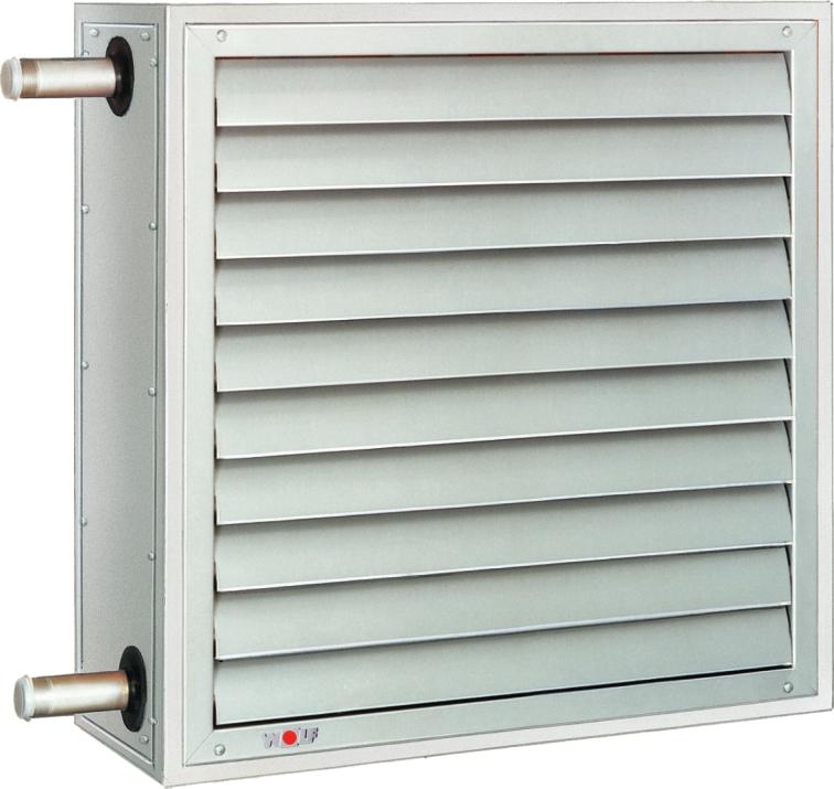
4 Basic unit Casing Sectional frame, welded and galvanised, consisting of pentapost profiles. Casing panels galvanised sheet steel. Rear panel incorporates deep-drawn intake nozzle. Discharge louvre with individually adjustable vanes. Dimensions: A B C Fan/Motors Axial fan with aluminium impeller, steel hub and protection grille. Low-noise, maintenance-free motors, direct drive to impeller, suitable for any installed position. Heat exchanger: Copper-Aluminium / galvanized steel Part.No. Part.No. Part.No. Part.No. Type / / / / Type / / / / Type / / / / Type / / / / - Type D / / / / Standard configuration Special drives Three-phase motor 3 x 400 V, 50 Hz, star circuit: low speed; Delta circuit: high speed Degree of protection IP 54, Insulation class F; Ball bearings with special grease filling for -25 bis C For any installed position, maintenance-free Windings protected against temperature excursion by integral thermo contacts which shut down the motor if it overheats, by interrupting the control circuit in the single-stage/multi-stage switch or controller. The drive restarts automatically when the temperature in the winding drops below the restart threshold. Winding protection effective only in conjunction with a single-stage/multi-stage switch or automatic controller. See pages for wiring options. Use in conjunction with other, commercially available switches or speed controllers voids the manufacturer s guarantee for the motor. See performance tables on Pages 6-13 for motor output ratings. Single-phase A.C. motor 230 V, 50 Hz, high speed only, low speed with 5-stage switch Motor output (kw) 0,14 0,14 0,18 - Current consumption (A) 2,0 2,0 2,2 - Part.No Degree of protection IP 54, Insulation class F Winding protection same as standard motor or thermo contacts connected in series with motor winding by others. The drive restarts automatically when the temperature in the winding drops below the restart threshold. See page 27 for external wiring. Progressive three-phase motor 3x400V, 50 Hz for control system DigiPro Motor output (kw) 0,075 0,14 0,2 0,45 Curr. consumpt.υ/ (A) 0,4 0,6 0,85 1,7 Part.No Degree of protection IP 54, Insulation class F, ball bearing with special llubricant for -25 bis +140 C Degree of protection P 54, insulaton class F, ball bearing with special grease for -25 upto +140 C, suitable for any installation position, maintenance-free. Winding protection by integrated thermo-contacts, which interrupts the control current circuit in the switch or control box and and shuts down the motor consequently. the drive restarts automatically when the temperature in the winding drops below the restart threshold. Winding protection effective only in conjunction with a switch or controller. Explosion-proof motor E Ex e II T3, 3 x 230 V/, oder 3 x 400 V/Υ, 50 Hz Motor output (kw) 0,25 0,25 0,55 0,55 Current consumpt. Υ/ (A) 0,79/1,37 0,79/1,37 1,66/2,90 1,66/2,90 Part.No Degree of protection IP 54, Insulation class B, see page 42 for external wiring.
 Flange and mating flange for steam Important note: For")

5 Basic unit Heat exchanger Co/Al heat exchanger Five types of heat exchangers per unit heater type for LPHW. MPHW or steam (code D). Heat exchanger made of Co/Al, steel header, withdrawable to side Galvanised sheet-steel frame LPHW and MPHW threaded inlet/oulet (inch system) Flange and mating flange for steam Important note: For LPHW or MPHW: threaded adapters for PN 16 up to 140 C Water inlet on air outlet at top/bottom Water outlet on air intake at top/bottom Connections on right/left hand side in direction of air flow See performance table for pipe connection sizes For steam: flange and mating flange for saturated steam, max. 9 bar Steam connection at top Condensate return at bottom Connection on left hand side only in direction of air flow See performance table for pipe connection sizes. Alternative: Steel / galvanised heat exchanger. Heat exchanger and header both made of galvanised steel and withdrawable to side suitable for LPHW, MPHW or steam D Frame made of galvanised sheet steel Flange/mating flange connections Electric heating coil incl. highlimit lock out Dimensions: a b c Heating output stages: kw 20 kw 25 kw 35 kw Higher performance on request Circuiting: 12 kw: 4-stage 1/4, 2/4, 3/4, 4/4 20 kw: 4-stage 1/4, 2/4, 3/4, 4/4 25 kw: 5-stage 1/5, 2/5, 3/5, 4/5, 5/5 35 kw: 5-stage 1/5, 2/5, 3/5, 4/5, 5/5 To avoid overheating, pay attention to the following minimum air volumes: horizontal air flow Vmin (m³/h) vertical air flow Vmin (m³/h) Protective measures: In any case it has to be secured that the electric heater is switched off when the air volume is falling below the indicated minimum. Additionally, the electric heater may only be set into operation by one or several magnetic switches whose control circuit leads over the automatic overheating controllers wired in line. 5
6 Performance tables For LPHW For saturated steam Type D Speed [min -1 ] Air vol. V O [m³/h] t on [ C] kw C kw C kw C kw C kw C kw C kw C kw C t on [ C] kw C kw C ,7-2 9,5 0 15,1 5 13,2 7 17, , , , , , ,5 2 8,5 3 13,5 8 11, , , , , , , ,4 6 7,4 7 11, , , , , , , ,9 29 LPHW ± 0 7,2 10 6, ,3 15 9, , , , ,0 27 1,1 ± 0 22, , / ,1 13 5,5 14 8,8 18 7, ,5 22 9, , ,1 29 bar , , ,0 17 4,5 18 7,3 21 6,4 22 8,8 24 7, ,9 29 9, , , ,0 21 3,5 21 5,8 24 5,1 24 7,0 27 6,1 28 8,8 30 7, , , ,9 24 2,6 25 4,3 27 3,8 27 5,3 29 4,6 30 6,6 32 5, , , ,9 0 10,5 1 16,7 7 14,6 9 19, , , , , , ,7 4 9,5 5 15, , , , , , , , ,5 8 8,5 9 13, , , , , , , ,5 32 LPHW ± 0 8,4 11 7, , , , , , ,8 31 1,5 ± 0 24, , / ,3 15 6, ,4 20 9, , , , ,9 32 bar , , ,2 19 5,5 19 8,8 23 7, ,5 27 9, , , , , ,1 22 4,5 23 7,3 26 6,4 27 8,8 29 7, ,9 34 9, , , ,0 26 3,6 26 5,8 29 5,1 30 7,0 32 6,2 33 8,8 36 7, , , ,7 0 10,4 1 16,8 7 14,7 9 20, , , , , , ,6 4 9,4 5 15, , , , , , , , ,4 7 8,4 9 13, , , , , , , ,2 34 LPHW ± 0 8,3 11 7, , , , , , ,5 32 2,0 ± 0 26, , / ,2 15 6, ,5 20 9, , , , ,6 34 bar , , ,1 18 5,5 19 9,0 23 7, ,9 28 9, , , , , ,0 22 4,5 23 7,5 26 6,6 27 9,2 30 8, ,5 35 9, , , ,0 26 3,6 26 6,0 29 5,3 30 7,4 32 6,5 34 9,4 37 8, , , ,1 3 12,6 5 20, , , , , , , , ,0 7 11,5 8 18, , , , , , , , , , , , , , , , , ,6 38 LPHW ± 0 10,7 14 9, , , , , , ,2 40 3,0 ± 0 28, , / ,5 18 8, , , , , , ,3 42 bar , , ,4 22 7, , , , , , , , , ,3 25 6, ,7 31 9, , , , , , , ,3 29 5,6 30 9,1 34 8, ,1 38 9, , , , , ,6 6 14,7 8 23, , , , , , , , , , , , , , , , , , , , , , , , , , , ,9 44 LPHW ± 0 13, , , , , , , ,8 47 5,0 ± 0 32, , / , , , , , , , ,9 49 bar , , ,7 25 9, , , , , , , , , ,6 29 8, , , , , , , , , ,5 32 7, , , , , , , , , ,9 9 16, , , , , , , , , , , , , , , , , , , , , , , , , , , , ,1 50 LPHW ± 0 15, , , , , , , ,3 55 9,0 ± 0 37, , / , , , , , , , ,4 57 bar , , , , , , , , , , , , , , , , , , , , , , ,8 35 9, , , , , , , , ,3 70 Motor output [kw] (3 x 400 V) min. 0,075 min. 0,027 min. 0,075 min. 0,027 min. 0,075 min. 0,027 min. 0,075 min. 0,027 min. 0,075 min. 0,027 Curr. consumpt. [A] (3 x 400 V) max. 0,4 max. 0,25 max. 0,4 max. 0,25 max. 0,4 max. 0,25 max. 0,4 max. 0,25 max. 0,4 max. 0,25 Air throw, wall mounted [m]* 15,5 12,5 14, ,5 12, ,5 12,5 Air throw, ceiling mount. [m]* 5,7 4,7 5,4 4,5 5,0 4,2 4,8 4,0 5,7 4,7 Sound pressure level db[a]** Water capacity [litres] 0,7 1,0 1,1 1,8 Heat exchanger connections R ¾ R 1 R 1 R 1 DN 40 - DN 20 * - t room = 10 K ** Sound pressure level measured 5 m from intake, room with average absorption; enclosed space approx m³. 6
7 25 For MPHW Hydraulic resistance [kpa] Type Speed [min -1 ] Air vol. V O [m³/h] t LE [ C] kw C kw C kw C kw C kw C kw C , , , , , , , , , , , , , , , , , ,5 51 MPHW ± 0 19, , , , , , / , , , , , , , , , , , , , , , , , , , , , , , , , , , , , , , , , , , , , , , , , ,4 57 MPHW ± 0 22, , , , , , / , , , , , , , , , , , , , , , , , , , , , , , , , , , , , , , , , , , , , , , , , ,2 58 MPHW ± 0 22, , , , , , / , , , , , , , , , , , , , , , , , , , , , , , , , , , , , , , , , , , , , , , , , ,1 60 MPHW ± 0 22, , , , , , / , , , , , , , , , , , , , , , , , , , , , , , , , , , , , , , , , , , , , , , , , ,1 64 MPHW ± 0 24, , , , , , / , , , , , , , , , , , , , , , , , , , , , , , ,0 78 Pages Air throws (as influenced by heat increase and discharge accessories) Page 41: Heating output Air volume and air outlet temperatures (as influenced by accessories and speeds) Page 42: Speeds table (in combination with single-stage/ multistage switches) Sound pressure level (as a function of speed) Motor output [kw] (3 x 400 V) min. 0,075 min. 0,027 min. 0,075 min. 0,027 min. 0,075 min. 0,027 Curr. consumpt. [A] (3 x 400 V) Air throw, wall-mounted [m]* Air throw, ceiling-mount. [m]* Sound pressure level db[a]** max. 0,4 15,5 5,7 56 max. 0,25 12,5 4,7 50 max. 0,4 14,5 5,4 56 max. 0, ,5 50 max. 0,4 13 5,0 56 max. 0,25 10,5 4,2 50 Water capacity [litres] 0,7 1,0 1,1 Heat exchanger connections R ¾ R 1 R 1 7
8 Performance tables For LPHW For saturated steam Type D Speed [min -1 ] Air vol. V O [m³/h] t on [ C] kw C kw C kw C kw C kw C kw C kw C kw C t on [ C] kw C kw C ,1 0 16,5 3 24,0 4 19,5 7 31, , , , , , ,9 4 14,8 6 21,4 7 17, , , , , , , ,8 7 13,1 9 18, , , , , , , ,2 31 LPHW ± 0 13, , , , , , , ,9 28 1,1 ± 0 37, , / ,7 15 9, , , , , , ,1 29 bar , , ,6 18 8, ,6 20 9, , , , , , , ,7 21 6,4 23 9,2 23 7, , , , , , , ,7 25 4,8 26 6,9 26 5,7 27 9,7 29 7, ,2 32 8, , , ,2 2 18,3 4 26,6 6 21,5 9 35, , , , , , ,1 5 16,5 8 24,0 9 19, , , , , , , ,9 9 14, , , , , , , , ,8 33 LPHW ± 0 15, , , , , , , ,6 32 1,5 ± 0 40, , / , , , , , , , ,8 33 bar , , ,7 20 9, , , , , , , , , ,7 23 8, ,6 25 9, , , , , , , ,7 27 6,4 28 9,3 28 7, , , , , , , ,3 2 18,4 5 26,7 6 21,8 9 36, , , , , , ,1 6 16,7 8 24,2 9 19, , , , , , , ,0 9 14, , , , , , , , ,4 36 LPHW ± 0 15, , , , , , , ,0 34 2,0 ± 0 43, , / , , , , , , , ,2 35 bar , , ,9 20 9, , , , , , , , , ,9 23 8, ,9 25 9, , , , , , , ,9 27 6,6 28 9,6 28 7, , , , , , , ,7 5 22,0 8 31, , , , , , , , ,5 9 20, , , , , , , , , , , , , , , , , , ,1 40 LPHW ± 0 20, , , , , , , ,4 41 3,0 ± 0 48, , / , , , , , , , ,6 43 bar , , , , , , , , , , , , , , , , , , , , , , , , , , , , , , , , ,1 9 25, , , , , , , , , , , , , , , , , , , , , , , , , , , , ,2 46 LPHW ± 0 24, , , , , , , ,7 49 5,0 ± 0 54, , / , , , , , , , ,9 51 bar , , , , , , , , , , , , , , , , , , , , , , , , , , , , , , , , , , , , , , , , , , , , , , , , , , , , , , , , , , , , , ,7 53 LPHW ± 0 28, , , , , , , ,8 56 9,0 ± 0 62, , / , , , , , , , ,0 58 bar , , , , , , , , , , , , , , , , , , , , , , , , , , , , , , , ,9 73 Motor output [kw] (3 x 400 V) 0,14 0,065 0,14 0,065 0,14 0,065 0,14 0,065 0,14 0,065 Curr. consumpt. [A] (3 x 400 V) 0,6 0,4 0,6 0,4 0,6 0,4 0,6 0,4 0,6 0,4 Air throw, wall-mounted [m]* , , Air throw, ceiling-mount. [m]* 5,6 4,1 5,5 3,9 5,0 3,6 4,5 3,3 5,6 4,1 Sound pressure level db[a]** Water capacity [litres] 1,0 1,5 2,0 2,5 Heat exchanger connections R ¾ R 1 R 1 R 1 DN 40 -DN 20 * - t room = 10 K ** Sound pressure level measured 5 m from intake, room with average absorption; enclosed space approx m³ 8
![40 For MPHW Hydraulic resistance [kpa] Type 1 2 3 Speed [min -1 ] 1350 1000 1350 1000 1350 1000 Air vol.](/docs-images/88/115998172/images/9-0.jpg "V O [m³/h] 3500 2500 3400 2400 3100 2200 t LA t LA t LA t LA t LA t LA t LE [ C] kw C kw C kw C kw C kw C kw C - 15 43,8 18 35,9 23 52,1 26 42,0 31 67,4 43 53,1 49-10 41,5 22 34,1 27 49,4 29 39,8 35")
9 40 For MPHW Hydraulic resistance [kpa] Type Speed [min -1 ] Air vol. V O [m³/h] t LA t LA t LA t LA t LA t LA t LE [ C] kw C kw C kw C kw C kw C kw C , , , , , , , , , , , , , , , , , ,7 55 MPHW ± 0 37, , , , , , / , , , , , , , , , , , , , , , , , , , , , , , , , , , , , , , , , , , , , , , , , ,3 60 MPHW ± 0 41, , , , , , / , , , , , , , , , , , , , , , , , , , , , , , , , , , , , , , , , , , , , , , , , ,8 62 MPHW ± 0 41, , , , , , / , , , , , , , , , , , , , , , , , , , , , , , , , , , , , , , , , , , , , , , , , ,4 64 MPHW ± 0 42, , , , , , / , , , , , , , , , , , , , , , , , , , , , , , , , , , , , , , , , , , , , , , , , ,3 68 MPHW ± 0 46, , , , , , / , , , , , , , , , , , , , , , , , , , , , , , ,4 82 Page 38-40: Air throws (as influenced by heat increase and discharge accessories ) Page 41: Heating output Air volume and air outlet temperatures (as influenced by accessories and speeds) Page 42: Speeds table (in combination with single-stage/ multistage switches) Sound pressure level (as a function of speed) Motor output [kw] (3 x 400 V) Curr. consumpt. [A] (3 x 400 V) Air throw, wall-mounted [m]* Air throw, ceiling-mount. [m]* Sound-pressure level db[a]** Water capacity [litres] Heat exchanger connections 0,14 0,065 0,14 0,065 0,14 0,065 0,6 0,4 0,6 0,4 0,6 0, , ,5 5,6 4,1 5,5 3,9 5,0 3, ,0 1,5 2,0 R ¾ R 1 R 1 9
10 Performance tables For LPHW For saturated steam Type D Speed [min -1 ] Air vol. V O [m³/h] t on [ C] kw C kw C kw C kw C kw C kw C kw C kw C t on [ C] kw C kw C ,6 2 28,6 4 43,6 7 36, , , , , , , ,2 5 25,6 7 39, , , , , , , , ,7 9 22, , , , , , , , ,0 33 LPHW ± 0 23, , , , , , , ,5 29 1,1 ± 0 61, , / , , , , , , , ,6 31 bar , , , , , , , , , , , , , , , , , , , , , , ,2 26 8, , , , , , , , , ,1 4 31,5 6 48, , , , , , , , ,6 7 28,5 9 43, , , , , , , , , , , , , , , , , ,5 36 LPHW ± 0 26, , , , , , , ,1 33 1,5 ± 0 67, , / , , , , , , , ,3 35 bar , , , , , , , , , , , , , , , , , , , , , , , , , , , , , , , , ,0 4 32,4 6 49, , , , , , , , ,6 8 29, , , , , , , , , , , , , , , , , , ,8 39 LPHW ± 0 27, , , , , , , ,2 36 2,0 ± 0 72, , / , , , , , , , ,2 37 bar , , , , , , , , , , , , , , , , , , , , , , , , , , , , , , , , ,0 8 38, , , , , , , , , , , , , , , , , , , , , , , , , , , , ,2 43 LPHW ± 0 34, , , , , , , ,6 43 3,0 ± 0 79, , / , , , , , , , ,7 45 bar , , , , , , , , , , , , , , , , , , , , , , , , , , , , , , , , , , , , , , , , , , , , , , , , , , , , , , , , , , , , , ,0 49 LPHW ± 0 41, , , , , , , ,7 51 5,0 ± 0 90, , / , , , , , , , ,8 53 bar , , , , , , , , , , , , , , , , , , , , , , , , , , , , , , , , , , , , , , , , , , , , , , , , , , , , , , , , , , , , , ,1 57 LPHW ± 0 48, , , , , , , ,6 58 9,0 ± 0 103, , / , , , , , , , ,6 60 bar , , , , , , , , , , , , , , , , , , , , , , , , , , , , , , , ,1 77 Motor output [kw] (3 x 400 V) 0,2 0,06 0,2 0,06 0,2 0,06 0,2 0,06 0,2 0,06 Curr. consumpt. [A] (3 x 400 V) 0,85 0,45 0,85 0,45 0,85 0,45 0,85 0,45 0,85 0,45 Air throw, wall-mounted [m]* Air throw, ceiling-mount. [m]* 7,1 5,3 6,9 5,1 6,1 4,5 5,8 4,4 7,1 5,3 Sound-pressure level db[a]** Water capacity [litres] 2,5 3,5 3,5 5,5 Heat exchanger connections R 1 R 1¼ R 1¼ R 1¼ DN 50 -DN 25 * - t room = 10 K ** Sound pressure level measured 5 m from intake, room with average absorption; enclosed space approx m³ 10
![For MPHW Type 1 2 3 Speed [min -1 ] 900 700 900 700 900 700 Air vol.](/docs-images/88/115998172/images/11-0.jpg "V O [m³/h] 5300 4000 5200 3900 4600 3500 Hydraulic resistance [kpa] 63 t on t on t on t on t on t on t LE [ C] kw C kw C kw C kw C kw C kw C - 15 72,2 21 61,0 25 93,2 33 77,5 38 106,3 46 87,7 51-10")
11 For MPHW Type Speed [min -1 ] Air vol. V O [m³/h] Hydraulic resistance [kpa] 63 t on t on t on t on t on t on t LE [ C] kw C kw C kw C kw C kw C kw C , , , , , , , , , , , , , , , , , ,9 57 MPHW ± 0 61, , , , , , / , , , , , , , , , , , , , , , , , , , , , , , , , , , , , , , , , , , , , , , , , ,2 63 MPHW ± 0 67, , , , , , / , , , , , , , , , , , , , , , , , , , , , , , , , , , , , , , , , , , , , , , , , ,0 65 MPHW ± 0 69, , , , , , / , , , , , , , , , , , , , , , , , , , , , , , , , , , , , , , , , , , , , , , , , ,8 67 MPHW ± 0 71, , , , , , / , , , , , , , , , , , , , , , , , , , , , , , , , , , , , , , , , , , , , , , , , ,3 71 MPHW ± 0 76, , , , , , / , , , , , , , , , , , , , , , , , , , , , , , ,1 85 Page 38-40: Air throws (as influenced by heat increase and discharge accessories) Page 41: Heating output Air volume and air outlet temperatures (as influenced by accessories and speeds) Page 42: Speeds table (in combination with single-stage/ mulitstage switches) Sound pressure (as a function of speed) Motor output [kw] (3 x 400 V) Curr. consumpt. [A] (3 x 400 V) Air throw, wall-mounted [m]* Air throw, ceiling-mount. [m]* Sound-pressure level db[a]** Water capacity (litres) Heat exchanger connections 0,2 0,06 0,2 0,06 0,2 0,06 0,85 0,45 0,85 0,45 0,85 0, ,1 5,3 6,9 5,1 6,1 4, ,5 3,5 3,5 R 1 R 1 ¼ R 1¼ 11
12 Performance tables For LPHW For saturated steam Type D Speed [min -1 ] Air vol. V O [m³/h] t on [ C] kw C kw C kw C kw C kw C kw C kw C kw C t on [ C] kw C kw C ,1 2 48,1 4 72,8 7 60, , , , , , , ,2 5 43,1 7 65, , , , , , , , ,3 9 38, , , , , , , , ,9 33 LPHW ± 0 39, , , , , , , ,7 30 1,1 ± 0 104, , / , , , , , , , ,7 31 bar , , , , , , , , , , , , , , , , , , , , , , , , , , , , , , , , ,9 4 53,0 6 80,4 9 66, , , , , , , ,0 7 48,0 9 72, , , , , , , , , , , , , , , , , ,3 36 LPHW ± 0 45, , , , , , , ,4 34 1,5 ± 0 113, , / , , , , , , , ,3 35 bar , , , , , , , , , , , , , , , , , , , , , , , , , , , , , , , , ,6 4 54,5 7 81, , , , , , , , ,6 8 49, , , , , , , , , , , , , , , , , , ,6 39 LPHW ± 0 47, , , , , , , ,2 37 2,0 ± 0 121, , / , , , , , , , ,1 38 bar , , , , , , , , , , , , , , , , , , , , , , , , , , , , , , , , ,5 8 64, , , , , , , , , , , , , , , , , , , , , , , , , , , , ,3 43 LPHW ± 0 58, , , , , , , ,6 44 3,0 ± 0 134, , / , , , , , , , ,5 46 bar , , , , , , , , , , , , , , , , , , , , , , , , , , , , , , , , , , , , , , , , , , , , , , , , , , , , , , , , , , , , , ,0 49 LPHW ± 0 70, , , , , , , ,5 52 5,0 ± 0 152, , / , , , , , , , ,4 54 bar , , , , , , , , , , , , , , , , , , , , , , , , , , , , , , , , , , , , , , , , , , , , , , , , , , , , , , , , , , , , , ,6 57 LPHW ± 0 81, , , , , , , ,0 59 9,0 ± 0 174, , / , , , , , , , ,8 61 bar , , , , , , , , , , , , , , , , , , , , , , , , , , , , , , , ,7 76 Motor output [kw] (3 x 400 V) 0,45 0,15 0,45 0,15 0,45 0,15 0,45 0,15 0,45 0,15 Curr. consumpt. [A] (3 x 400 V) 1,7 1,1 1,7 1,1 1,7 1,1 1,7 1,1 1,7 1,1 Air throw, wall-mounted [m]* Air throw, ceiling-mount.[m]* 7,7 5,6 7,6 5,5 7,1 5,0 6,6 4,6 7,7 5,6 Sound-pressure level db[a]** Water capacity [litres] 2,5 3,5 3,5 5,5 Heat exchanger connections R 1 R 1½ R 1½ R 1½ DN 65 -DN 32 * - t room = 10 K ** Sound pressure level measured 5 m from intake, room with average absorption; enclosed space approx m³ 12
![For MPHW Type 1 2 3 Speed [min -1 ] 900 700 900 700 900 700 Air vol.](/docs-images/88/115998172/images/13-0.jpg "V O [m³/h] 9000 6700 8800 6500 8300 6000 Hydraulic resistance [kpa] 100 t LA t LA t LA t LA t LA t LA t LE [ C] kw C kw C kw C kw C kw C kw C - 15 122,5 21 102,7 26 156,1 32 128,5 37 196,3 48 155,6")
13 For MPHW Type Speed [min -1 ] Air vol. V O [m³/h] Hydraulic resistance [kpa] 100 t LA t LA t LA t LA t LA t LA t LE [ C] kw C kw C kw C kw C kw C kw C , , , , , , , , , , , , , , , , , ,0 59 MPHW ± 0 104, , , , , , / , , , , , , , , , , , , , , , , , , , , , , , , , , , , , , , , , , , , , , , , , ,9 65 MPHW ± 0 115, , , , , , / , , , , , , , , , , , , , , , , , , , , , , , , , , , , , , , , , , , , , , , , , ,1 68 MPHW ± 0 118, , , , , , / , , , , , , , , , , , , , , , , , , , , , , , , , , , , , , , , , , , , , , , , , ,3 70 MPHW ± 0 121, , , , , , / , , , , , , , , , , , , , , , , , , , , , , , , , , , , , , , , , , , , , , , , , ,9 73 MPHW ± 0 129, , , , , , / , , , , , , , , , , , , , , , , , , , , , , , ,4 87 Page 38-40: Air throws (as influenced by heat increase and discharge accessories) Page 41: Heating output Air volume and air outlet temperatures (as influenced by accessories and speeds) Page 42: Speeds table (in combination with single-stage/ multistage switches) Sound pressure (as a function of speed) Motor output [kw] (3 x 400 V) Curr. consumpt. [A] (3 x 400 V) Air throw, wall-mounted [m]* Air throw, ceiling-mount. [m]* Sound-pressure level db[a]** Water capacity [litres] Heat exchanger connections 0,45 0,15 0,45 0,15 0,45 0,15 1,7 1,1 1,7 1,1 1,7 1, ,7 5,6 7,6 5,5 7,1 5, ,5 5,5 7,5 R 1 R 1½ R 1½ 13

 in both flow and return.")


14 Shut-off sets / Fastening accessories Shut-off sets for heat exchangers Shut-off set straight way or rectangular type for flow and return of heat exchanger 25: type 2/ 3/4, 40: type 2/3/4, 63: Type 1, 100: Type 1. suitable for LPHW/MPHW up to max 110 C and an operating pressure up to max. 10 bar, consisting of: Screwed fitting 1 for connection of flow and return including flat sealing. Air separator with automatic shut-off valve in the flow. Filling and draining cock with cover and hose connection in the return. Ball valves with internal thread 1 in both flow and return. Connection possibility 3/4 external thread (i.e. for thermometer) in both flow and return. straight-way type Part.-No rectangular type Part.-No Fastening brackets For wall and ceiling installation, of pentapost sheet steel 2mm, galvanized. Complete set consisting of: 2 Brackets Hexagon screws for assembly to -Unit. Ø 10 mm a b c d e f g h i Part.No x x x x Fastening set for concrete bar-vertical For fastening an -Unit to a concrete bar by suspending it into a pre-assembled fixing rail. Dowels and screws to be provided on site. Set consisting of: fixing rail, 2 suspending rails (galvanized sheet steel), screws and nuts. Part.No Fixing rail Suspending rail Fastening brackets -Unit 14
 fixing rail.")
, 4 pcs clamping jaws, screws and nuts. Fastening set for steel bar - horizontal and inclined without inclination equalization.")
15 Fastening accessories Fastening set fot steel barvertical b t Part.-No For fastening an -unit to a steel bar by suspending it into a preassembled (via clamping jaws) fixing rail. Suitable for all types of steel bars at a flange width b of mm, and a flange thickness t of 6-21 mm. Consisting of: Fixing bracket, 2 pcs. suspending rails (galvanized sheet steel), 4 pcs clamping jaws, screws and nuts. Fastening set for steel bar - horizontal and inclined without inclination equalization. For fastening an -Unit to a horizontal or inclined steel bar at a flange width b of mm, and a flange fhickness t of 6-21 mm. Consisting of: 2 pcs. suspending rails (galvanized sheet steel), 4 pcs clamping jaws, screws and nuts. * Threaded rods size M8 on site. Installation examples: b t Part.-No * Direct fastening on horizontal steel bar direct fastening on inclined steel bar Indirect fastening on horizontal steel bar Attention: Prior to the application of fastening sets the static conditions of the concrete or steel bars have to be checked and taken into account. Assembly exclusively with basic units at a total depth of 300 mm. 15
, 4 pcs. clamping jaws, 4 pcs.")

16 Fastening accessories Fastening set for steel bar - inclined with inclination equalization For fastening an -Unit to a steel bar at a flange width b of mm, and a flange thickness t of 6-21 mm consisting of: 2 pcs. suspending rails (galvanized sheet steel), 4 pcs. clamping jaws, 4 pcs. inclination equalization clamping jaws Suspending rail Threaded rods M 8 (on site) Fastening brackets -Unit Inclination equalization b t Part.No Angle brackets For wall-mount or ceiling-mount unit heaters complete with mixed air, recirculating air, fresh air or filter section galvanised. Four angle brackets are required for installation. These brackets are enclosed with the intake accessory, as appropriate. (sealing towards wall / ceiling on site) 16 a b c Part.No

 a b c d e Part.No.")

17 Discharge accessories Discharge cone Increases the air throw of high-mounted unit heaters. (See Page 39 for air throws) a b c d Part.No Discharge nozzle For long air throws, suitable for air curtains at doors. Oulet temperature for air curtain approx C higher than room temperature. (See Page 39 for air throws) a b c d e Part.No Four-way-discharge With adjustable vanes, suitable for heating low-ceilinged rooms, air is distributed uniformly to all four sides. a b c Part.No


18 Discharge accessories Discharge cross Improves air flow through the room and temperature distribution by thoroughly mixing the current of warm air with the air in the room. The temperature of the warm air stream is lower, so the air throw is longer. Reduces air temperature close to the ceiling, so less heat loss due to ventilation and transmission - up to 15% energy savings. (See Pages for air throws). Part.No Wide-spread discharge Spreads the warm air stream discharged to the side. Air discharge spread up to approx. 120 ; louvre vanes individually adjustable, horizontally and vertically. Part.No Induction louvre Wall-mounted unit Induction louvre for optimising air throw and temperature distribution Functional description The induction louvre divides the warm air stream from the unit heater and inducts secondary air (ambient air) from behind the vanes directly into the core of the warm air stream. The inducted secondary air causes intensive mixing of the warm air with the ambient air over a very short distance, thus reducing the temperature of the warm air stream. This temperature reduction decreases the ascending force of the warm air and increases the air throw, particularly when the unit heater is operating at high leaving air temperatures. The induction louvre (and thus the direction of the warm air stream) is adjustable either by hand or with the aid of an actuator and can therefore be set to suit any operating conditions or room. Ceiling-mounted unit Energy savings Avoids high temperatures close to the ceiling and the associated heat losses by ventilation and transmission. Energy savings up to 15% are possible. Easily retrofitted for upgrading The induction louvre is easily installed, so upgrading existing systems poses no problems. Scope of supply Induction louvre monted to -Unit, with actuator 230V/50 Hz suitable for drive via key button. Alternative: Induction lowre with secondary air cone, manually adjustable. 18


19 Intake accessories Dimensions basic unit with induction louvre a b c d Induction louvre for wall-mounted unit manual setting Part.No with actuator 230 V Part.No with actuator 24V for control system DigiPro fitted and wired Induction louvre for ceiling-mounted unit manual setting Part.No with actuator 230 V Part.No with actuator 24V for control system DigiPro fitted and wired Key button for 230V/50Hz Actuator for induction louvre Part.No Part.No for surface / concealed type installation; for progressive adjustment of the induction louvre and optimisation of the airthrow. surface/concealed type switch Operating voltage Current max. 230 V 10 A Degree of protection IP 20 Part.No auxiliary clamp on site Actuator openclosed 230V induction louvre 19

![2 3 4 1 2 3 4 1 2 3 4 Air throw [m]* high speed 19 18 16 15 27 26 23 21 29 27 25 23 36 35 34 32 low speed 16 15 13 12 20 19 16 14 22 20 18 17 30 28 26 25 * Figures represent air throws at defined](/docs-images/88/115998172/images/20-1.jpg "operating conditions.")
20 Induction louvre consulting advice Clearances Clearances for wall-mounted units and clearances for ceiling-mounted units, vanes vertical. Ceiling-mounted unit, vanes deflected from 7-9m 9-11 m m m to wall 3-4 m 3-5 m 4-6 m 5-7 m from -12 m - 14 m - 16 m - 18 m to wall 4-6 m 5-7 m 6-8 m 7-9 m Air throw: wall-mounted unit Type Air throw [m]* high speed low speed * Figures represent air throws at defined operating conditions. (mixing temperature 10 K above room temperature) Height above floor, ceiling-mounted unit Type Height above floor [m]* 5 4,5 4 3,5 6 5,5 5 4,5 7 6,5 6 5,5 8 7,5 7 6,5 * The optimum vane angle depends on the height above floor. Higher above floor heights on request. Height wall-mounted unit with adaption cone and induction louvre A B C D E F Type Air volume [m³/h] Max. Height (m) Higher above floor heights on request. 20


21 Intake accessories Mixing box For adjusting the room s air change rate. Fresh air intake at rear, recirculated air intake at side or from above or below if mixing box is turned through 90. Stepless adjustment from recirculated air only through mixed air to fresh air only, manual or with 230 V stepless actuator. a b c d e f g Part.No Return air box Return air box has two side intake grilles for recirculating air; box can also be turned through 90 for intake from above and below. a b c d e Part.No Fresh air box Fresh air box has intake at rear, for connection to a wall shaft or fresh air duct. a b c Part.No


22 Intake accessories Damper for fresh air box a b Part.No. Galvanized damper for installation into fresh air box, sheet steel galvanized. For damper actuators see page Filter box With dust-trap filter insert for fresh air operation, filter class G4. Angle brackets optional. a b c Part.No Intake duct For recirculating air: improves circulation of air at floor level. Galvanised sheet steel. 22 a b c d e* f g h i k Part.No * 1 m additional length according to price list


23 Intake accessories Rain protection hood With bird screen (non-return flap optional) for roof-level fresh air intake. Connects to unit heater by means of roof lead-in box. a b c d Part.No Roof lead-in box Connects the unit heater to the rain protection hood. Roof sealing by others. Galvanised sheet steel. a b c Part.No Covering collar For roof passage. Galvanized sheet steel a b Part.No Intake hood with bird screen With bird screen, for fresh air intake through the wall (non-return flap optional). Galvanized sheet steel. a b c d e Part.No


24 Intake accessories Non return-flap for rain protection/intake hood For installation in rain protection hood or in wall penetration for intake hood. Galvanised sheet steel. a b c d Part.No Weatherproof louvre Weatherproof louvre incorporating bird screen. Galvanised sheet steel. a b c Part.No Weatherproof louvre with non-return flap Weatherproof louvre incorporating bird screen and non-return flap. Galvanised sheet steel. a b c Part.No Flexible connection Flexible connection, 4-hole profile; galvanized sheet steel. Part.No
25 Controllers, switching and automatic 25

 TK/11-12 2-stage switch DS for two-speed control of one or more unit heaters with full motor protection. Operating voltage Control voltage Switching capacity, max.")
26 Switching controllers 1-stage switch D1 for single-speed (on/off) control of one or more unit heaters with full motor protection. *Jumper as per motor rating plate Room thermostat Operating voltage Control voltage Switching capacity, max. Weight 400 V 230 V 3 kw 0,9 kg Degree of protection IP 54 Part.No ** No jumper with room thermostat Automatic start-up when winding temperature drops (motor). 1) TK/ stage switch DS for two-speed control of one or more unit heaters with full motor protection. Operating voltage Control voltage Switching capacity, max. Weight 400 V 230 V 4 kw 0,9 kg Degree of protection IP 54 Part.No Automatic start-up when winding temperature drops (motor). * Remove jumper if room thermostat is connected 1) TK/11-12 Note: 26 Use without switching controller for full motor protection voids the manufacturer s guarantee for the motor! Install in accordance with local power-utility regulations. Full motor protection switches for 3 x 230 V available on request.

27 Switching controllers A1 Ü controller (without explosion-proof switch) As full motor protection for single-speed motors, explosion-proof configuration. The A1Ü controller must be installed outside the hazar-dous area. Operating voltage Control voltage Switching capacity, max. Weight 3 x 400 V 230 V 3 kw 0,6 kg 1 explosion-proof switch 2 A1Ü relay 3 Explosion-proof fan Degree of protection IP 54 Part.No. without explosionproof switch Part.No. with explosionproof switch K1 Auxiliary contactor F1 Control fuse F2 Therm. motor circuit-breaker S1 Explosion-proof switch M1 Fan motor Installation locations: A1Ü outside hazardous area Explosion-proof switch = inside hazardous area Controller A2 For automatic 2-stage control of one or more unit heaters in conjunction with a 2-stage room thermostat or a 2-stage room thermostat timer. The 2-stage room thermostat or room thermostat timer in conjunction with the A2 controller selects speed 0, 1 or 2 in accordance with the required heating output. Operating voltage Control voltage Switching capacity, max. Weight 3 x 400 V 230 V 4 kw 2,0 kg Degree of protection IP 54 Part.No Note: Use without switching controller for full motor protection voids the manufacturer s guarantee for the motor. Install in accordance with local power-utility regulations. Full motor protection switches for 3 x 320 V available on request. 27

: Reclosing: switch position 0, then select required stage.")


28 Switching controllers 3-stage switch D 3-4 with reclosing lock-out for three-speed control of one or more unit heaters with full motor protection. Fan motor with thermo contact Jumper as per motor rating plate Operating voltage Control voltage Current, max. Weight 400 V 230 V 4 A 8 kg Degree of protection IP 20 Part.No Locking switch-off at winding overtemperature (motor): Reclosing: switch position 0, then select required stage. * Remove jumper if room thermostat is connected H1 = Function H2 = Failure S1/K1 = Contact seizure depending on manufacture type 1) TK / stage switch D For five-stage control of one or more unit heaters with full motor protection. Type D5-1 D5-3 D5-7 D5-12 Operating V voltage Control kw voltage Current max. A Weight kg 4,5 7,0 9,0 19,0 Degree of protection IP Fan motor with thermo contact Jumper as per motor rating plate Dimensions Type D5-1 D5-3 D5-7 D5-12 Width A Height B Depth C Part numbers: Type Part.No. * Remove jumper if room thermostat is connected H1 = Function H2 = Failure 1) TK / D D D D Automatic start-up when winding temperature drops (motor). 28
.")
 TK / 11-12 5-stage switch E 5-3 For five-stage control of one or")
29 Switching controllers 3-stage switch E 3-7T with reclosing lock-out for three-speed control of one or more unit heaters with single-phase a.c. motors and full motor protection. Fan motor with thermo contact Operating voltage Current max. Weight 230 V 7 A 4,5 kg Degree of saturation IP 40 Part.No Locking switch-off at winding overtemperature (motor). Reclosing: switch position 0, then select required stage. * Remove jumper if room thermostat is connected H1 = Function H2 = Failure S1/K1 = Contact seizure depending on manufacture type 1) TK / stage switch E 5-3 For five-stage control of one or more unit heaters with single-phase a.c. motors and full motor protection. Fan motor with thermo contacts Operating voltage Current, max. Weight 230 V 3 A 4,0 kg Degree of saturation IP 40 Part.No Automatic start-up when winding temperature drops (motor). * Remove jumper if room thermostat is connected 1) TK / Note: Use without switching controller for full motor protection voids the manufacturer s guarantee for the motor. Install in accordance with local power-utility regulations. 29
30 Actuators for fresh air or mixed air OPEN/CLOSED actuator, 230 V For motor-actuated operation of fresh air damper in conjunction with A1 automatic relay. starts up fresh air damper opens shuts down fresh air damper closes or antifreeze watchdog trips Stepless actuator, 230 V For stepless, motor-actuated operation of fresh air/return air dampers in conjunction with A1 automatic relay and a position controller in the control cabinet or surface mounted or integrated in the A1S automatic relay. starts up fresh air damper opens to preset setting, return air damper closes to the corresponding setting. shuts down fresh air damper closes, return air damper opens or antifreeze watchdog trips 100%. 30


31 Automatic controllers for damper actuators A1 automatic relay Auxiliary relay for automatic actuation of the fresh air damper with 230 V OPEN/CLOSED actuator. Open/Closed actuator Interchange 2 and 3 to reverse function A1 automatic relay Antifreeze thermostat When the unit heater shuts down or the antifreeze thermostat trips, the A1 automatic relay sets the actuator to the CLOSED position. When the starts up the relay sets the actuator to the OPEN position. Fresh air/return air selector switch (by others) Control voltage Switching capacity, max. 230 V 3 kw Weight 0,5 kg Degree of protection IP 54 Switching controller Open/Closed actuator Interchange 2 and 3 to reverse function Part.No A1 automatic relay A1S automatic relay Auxiliary relay with integral position controller for automatic actuation of the fresh air/return air dampers with 230 V stepless actuator. Stepless actuator When the unit heater shuts down or the antifreeze thermostat trips, the A1S automatic relay sets the actuator to the CLOSED position. When the starts up the relay sets the actuator to the position determined by the position controller. Position controller Control voltage Switching capacity, max. Weight 230 V 3 kw 0,5 kg Degree of protection IP 54 Switching controller Part.No

 A, cooling 5(2) A at 230 V/ 50 Hz, thermal feedback signal.")


, daytime and night-time temperatures can be set separately.")

32 Room thermostats Room thermostat Room thermostat with summer/winter switch Room thermostat with 2-stage control Room thermostat industrial version Room thermostat timer with daily/weekly programming Room thermostat timer with daily/weekly programming and 2-stage control 32 Plastic housing, 75 x 75 x 25 mm for surface mounting. Switching capacities: heating 10(4) A, cooling 5(2) A at 230 V / 50 Hz, thermal feedback signal. Temperature range 5-30 C Switching differential 0,5 K Degree of protection IP 30 Part.No Plastic housing, 75 x 75 x 25 mm for surface mounting. Switching capacity: heating 10(4) A, cooling 5(2) A at 230 V/ 50 Hz, thermal feedback signal. Temperature range 5-30 C Switching differential 0,5 K Degree of protection IP 30 Part.No Plastic housing,125 x 75 x 25 mm for surface mounting. In conjunction with the A2 automatic controller suitable for automatic 2-stage operation of the unit heater. Switching capacity 10(4) A at 230 V Temperature range 5-30 C Switching differential 0,5 K Differential of stages 1K Degree of saturation IP 30 Electric connection see A2 controller Part.No In metal housing with plastic front panel, 117 x 71 x 30 mm for surface-mounting. Switching capacity 15(8) A at 230 V / 50 Hz Temperature range 0-35 C Switching differential 0,5 K Degree of saturation IP 54 Part. No Plastic housing, 162 x 80 x 44 mm for socket installation, nighttime reduction with daily/weekly programming (selectable), daytime and night-time temperatures can be set separately. 24-hour-programme: programmable every 5 minutes, shortest switching interval 15 minutes. 7-hour-programme: programmable every 30 minutes, shortest switching interval 2 hours. Switching capacity: 5 A at 230 V / 50 Hz Temperature range 6-26 C Switching differential 0,2 K Degree of protection IP 30 Part.No In plastic housing 162 x 80 x 44 mm for socket installation, night time reduction with daily/weekly programming (selectable), daytime and night-time temperatures can be set seperately. 24-hour-programme: programmable every 5 minutes, shortest switching interval 15 minutes. 7-day-programme: programmable every 30 minutes, shortest switching interval 2 hours. Switching capacity 6 A at 230 V / 50 Hz Temperature range 6-26 C Switching differential adjustable 0,5-2,5 K Degree of saturation IP 30. Part.No In conjunction with the A2 automatic controller suitable for automatic 2-stage operation of the unit heater.


33 Thermostats, control interface box Room thermostat timer with daily/weekly programming and remote temperature sensor. Antifreeze thermostat mounted Differential pressure gauge Intermediate terminal box In plastic housing 162 x 80 x 44 mm for socket installation nighttime reduction with daily/weekly programming (selectable), daytime and night-time temperatures can be set seperately. 24-hour-programme: programmable every 5 minutes, shortest switching interval 15 minutes. 7-day-programme: programmable every 30 minutes, shortest switching interval 2 hours Switching capacity 10 A at 230 V / 50 Hz Temperature range 6-34 C Switching differential 0,2 K Degree of saturation IP 30 Cable for remote sensor, max. length 50 m Degree of protection IP 64 Part.No If the air outlet temperature drops below a preset value the antifreeze thermostat shuts down the unit heater, thus preventing frost damage to the heat exchanger. The unit heater restarts automatically when the air outlet temperature rises. The antifreeze thermostat must be connected in series with the thermo contacts. Switching capacity 10 A at 230 V / 50 Hz Range of adjustment 2 C to 20 C. Switching differential 2,5 K Degree of protection IP 43 Dimensions B x H x T 85 x 75 x 40 mm Part.No for filter control, only in combination with DigiPro Part.No Intermediate terminal box for parallel connection of max. 3 unit heaters with 3 x 400V, 50Hz motors. Degree of protection IP 54 Dimensions B x H x T 105 x 170 x 112 mm Part.No Control interface box Switching or automatic controller Control interface box For operating an unit in conjunction with a Wolf boiler. - Outdoor-temperature-sensitive control for radiators and underfloor heating. - Complete wiring with plugs - Priority circuit /SHW-storage to be selected deliberately via jumper - Connection for -circulating pump and SHW-storage charging pump - Storage thermostat SP 1 (substitute for electronic sensor) included in scope of supply - Application for swimming pool heating possible - Drive via potential free contact or drive phase of motor or thermostat drive Degree of protection IP 54 Dimensions B x H x T 220 x 170 x 110 mm Part.No

34 Control configurations Control configuration A Heating and ventilating in return air mode without damper actuator or heating and ventilating in fresh air only mode without return air with OPEN/CLOSED damper actuator. Description - Room temperature controlled by room thermostat or room thermostat timer. - Room thermostat timer for timed reduction of room temperature. - Antifreeze thermostat for fresh air mode: if the discharge temperature at the heating coil drops below the preset value, the actuator closes the fresh air damper and the fan is shut down. - OPEN/CLOSED damper actuator(230 V a.c.) for automatic actuation of the fresh air damper. (Damper opens when the unit heater starts up. Damper closes when the unit heater shuts down or if the antifreeze thermostat trips). - Control cabinet with: - Indicator lights for fan on and fan malfunction - DS speed selector switch for 2-stage fan operation or D5 for 5-stage fan operation. - Selector switch for heating/ventilation Note: This configuration can also be used to operate multiple unit heaters connected in parallel: the configuration limit is imposed by maximum permissible switching capacity or maximum permissible current. 34

35 Control configurations Control configuration B Heating and ventilating in mixed air mode with stepless damper actuator for variable fresh air/return air mix. Description - Room temperature controlled by room temperature sensor. - Room thermostat timer for timed reduction of room temperature. - Antifreeze thermostat for fresh air mode: if the discharge temperature at the heating coil drops below the preset value, the actuator closes the fresh air damper and the fan is shut down. - Stepless damper actuator (230 V a.c.) for automatic actuation of fresh air damper and return air damper (when unit heater starts up, dampers open to position set by position controller. Fresh air damper closes and return air damper opens when unit heater shuts down or if the antifreeze thermostat trips.) - Control cabinet with: - Position controller for remote control of fresh air/return air dampers - Timer for periodic room temperature reduction - Indicator lights for fan on and fan malfunction - DS speed selector switch for 2-stage fan operation or D5 for 5-stage fan operation - Selector switch for heating/ventilation Note: This configuration can also be used to operate multiple unit heaters connected in parallel: the configuration limit is imposed by maximum permissible switching capacity or maximum permissible current. 35

36 Control configurations Control configuration C Heating and ventilating with unit heater in continuous operation with stepless damper actuator for variable fresh air/return air mix; room temperature control with room temperature sensor for controlling a mixing valve with stepless actuator. Alternative to room-temperature control; supply air temperature control with supply air temperature sensor for controlling a mixing valve with stepless actuator. Description - Room temperature controlled by room temperature sensor. - Option: Supply air temperature control with supply air temperature sensor - Timer for periodic reduction of room air/supply air temperature or unit heater shutdown - Antifreeze thermostat for fresh air mode: if the discharge temperature at the heating coil drops below the preset value, the actuator closes the fresh air damper and the fan is shut down. - Stepless damper actuator (230 V a.c.) for automatic actuation of fresh air damper and return air damper (when unit heater starts up, dampers open to position set by position controller. Fresh air damper closes and return air damper opens when unit heater shuts down or if the antifreeze thermostat trips.) - Mixing valve with stepless actuator for inlet temperature adjustment as a function of room temperature or supply air temperature - Control cabinet with: - Position controller for remote control of fresh air/return air dampers - Timer for periodic room temperature reduction/ shutdown - Temperature setpoint controller for daytime temperature - Temperature setpoint controller for night-time temperature - Indicator lights for fan on and fan malfunction - DS speed selector switch for 2-stage fan operation or D5 for 5-stage fan operation. - Selector switch for ventilation/heating with reduction/heating off at night Note: This configuration can also be used to operate multiple unit heaters connected in parallel: the configuration limit is imposed by maximum permissible switching capacity or maximum permissible current. 36

37 Control DigiPro System configuration with control DigiPro Example for system configuration single units General controller Unit heater power gate module No.1 The control DigiPro is installed on top of the unit heater and completely wired. As an option the control DigiPro may be as well used i.e. for a seperate wall installation. This is applicable for either single units, unit groups or complete systems (several single units or unit groups) with several different temperature zones. Notice: Max. cable length 3m from unit to control. Longer distances on request. Control type not possible with electric heating coils. The control DigiPro provides a completely configurated system ready for connection, suitable for control and monitoring functions in ventilation systems. The minimum assembly consists of a general controller and a unit heater with a power gate module. The components are connected by means of a two-wire bus (ebus). It is possible to integrate up to 32 unit heaters (furnished with either a power gate module or a group module) into the bus system. Unit heater Powergate module No.2 Boiler Radioclock receiver Wireless remote control receiver Unit heater group module No.32 Demanding module The operation of the system does not require any knowledge or operation, configurated ex works. Cost intense programming is avoided. To provide communication between a mobile network and the general controller, the latter may be equipped with an ISDN-Interface. In case of disturbances messages are sent either to a mobile phone, fax or PC.. This increases the operation security and availability of the units significantly. Furthermore there is a LON-Interface available to connect the control to a LON-Bus, in order to combine the different systems in an intelligent way. General Controller GC Design - Two-shell casing protection class IP30 - Keyboard with 10 functional keys for easy operation - illuminated 4-line LCD-graphic display - additional connection for external sensor and room temperature sensor, external system start-up and collective operation status display possible Standard Functions - Either progressive or 2-speed control of fan-motor assemblies possible, depending on power gate module - Different operating modes adjustable: Standby, pre-heating program, auxiliary mode heating, quick heating, night ventilation, exhaust air management, quick ventilation, low noise operation, burner demand, induction louvre control, axial ceiling fan type LD-15 control, pump and mixing valve protection function - menu system with clear text display for an easy user guiding - 8 different temperature zones max. seperately controllable - 8 programmable on/off times per day and zone possible - 10 adjustable periods for vacation available 37

38 Control General Controller DigiPro Standard functions - easy automatic commissioning by reading out the client s specific data from the powergate modules - many basic adjustments already integrated ex works Standard monitoring functions - recording of failures with date, time, quantity - diagnosis and reasonableness monitoring of the system - sensor monitoring with automatic emergency service of the installation (selective) Optional functions - ISDN-Interface for service-sms to mobile telephone (accessory) - LON-Interface for interaction with a building monitoring bus (accessory) - radio clock module for automatic time synchronisation (accessory) - radio remote control for modification of fan speed and on alternative function (accessory) Master unit with power gate module Power gate module Temperature control via fan speed - electrical connections existing on unit heater are internally wired - optically appealing aluminium die cast casing with integrated mains isolator - extremely low fan noise via most modern motor capacity electronics, power gate module configurated for heating mode - 3 different fan capacity variations to be selected via power gate modules: Power gate module FHE 230 V~/2,2 kw for progressive speed control of fan/motor assembly Power gate module FHZ 400V~/2,2 kw for 2-speed control of fan/motor assembly Power gate module FHD 400V~/2,2 kw for progressive speed control of fan/motor assembly - Setting of address of outstanding unit via DIP-switches Standard functions - pre-programmed system specifically configurated in the factory - optimized tuning for individual systems and expandable for growing installations - type of control: temperature controlled fan speed - room temperature sensor for different temperature zones alternatively - room temperature sensor with set point adjuster - full motor protection via thermal cut out - various monitoring functions integrated (frost protection, fire protection, filter monitoring etc.) - integrated optional functions; i.e. mixing damper control, shut-off valve, fresh air damper open/ closed - mains supply and voltage supply of fan/motor assemblies of slave units Master unit with power gate module 38 Power gate module Temperature control via fan speed or mixing valve - existing electrical connections of the -unit are internally wired - optically appealing aluminium die cast casing with integrated mains isolator - extremely low fan noise via most modern motor capacity electronics, power gate module configurated for heating mode - 3 different fan capacity variations to be selected via power gate modules: Power gate module FKE 230 V~/2,2 kw for progressive speed control of fan/motor assembly and progressive drive of an induction louvre Power gate module FKZ 400V~/2,2 kw for 2-speed control of fan/motor assembly and progressive drive of an induction louvre Power gate module FKD 400V~/2,2 kw for progressive speed control of fan/motor assembly and progressive drive of an induction louvre - setting of address of outstanding unit via DIP-switches Standard functions - pre-programmed system specifically configurated in the factory - optimized tuning for individual systems and expandable for growing installations - types of control: temperature controlled fan speed or mixing valve control optional - room temperature sensor for different temperature zones alternatively-room temperature sensor with set point adjuster - full motor protection via thermal cut out - various monitoring functions integrated (frost protection, fire protection, filter monitoring etc.) - integrated optional functions: i.e. mixing damper control, control of axial ceiling fan LD-15, control of induction louvre, heating circuit pump control, mixing valve control, fresh air damper open/ closed

39 Control System Slave unit with group module Group module DigiPro An -master unit with a power gate module may be extended by max. up to 5 pcs. -slave units provided with a group module each to a system, consisting of 6 units. It has to be secured, that the max. nominal capacity of the power gate module is not exceeded. Mains supply and motor supply of the single group modules are provided by the power gate module. Electrical connections existing on unit heater are internally wired. 2 different configurations may be selected: a) Group module GUE, GUZ, GUD for return air and b) Group module GME, GMZ, GMD for mixed air 3 different fan/motor vvariations may be selected: a) Group module GUE, GME for 230V~/2,2 kw progressive b) Group module GUZ, GMZ for 400V~/2,2 kw 2-speed c) Group module GUD, GMD for 400V~/2,2 kw progressive Example system arrangement slave units Mains supply 230V~ Mains supply 230V~ or 400V~ Setting of address of outstanding unit via DIP-switches on the corresponding group module. Standard display: Full motor protection (thermal cutout) i.e. on 5... released. Frost protection thermostat (with mixed air operation) i.e. on 2... has switched off. Mains/motor supply Function group module 1 Master unit with power gate module 2 slave unit with group module e bus 3 slave unit with group module 4 slave unit with group module 5 slave unit with group module 6 slave unit with group module GUE 230V~ Progressive fan speed, return air function, for power gate module FHE GUZ 400V~ 2 fan speeds, return air function, for power gate module FHZ GUD 400V~ Progressive fan speed, return air function, for power gate module FHD GME 230V~ Progressive fan speed, progressive drive of mixed air damper, progressive induction louvre, for power gate module FHZ/FKZ GMZ 400V~ 2 fan speeds, progressive drive of mixed air damper, progressive induction louvre, for power gate module FHE/FKE GMD 400V~ Progressive fan speed, progressive drive of mixed air damper, progressive induction louvre, for power gate module FHD / FKD Accessories GBK Additional module Additional module required for different temperature zones (boiler demand via contact) SF1 Sinus filter With power gate module 400V progressive (FHD, FKD) and a motor cable length exceeding 50m from the master unit to the most distant slave unit, a sinus filter has to be installed at the output of the frequency converter. 39
40 Control System DigiPro Survey Master unit for return air or mixed air operation Fan drive 1 x 230V / 50Hz 3 x 400V / 50Hz progressive 2-speed progressive Power gate module Type FHE FKE FHZ FKZ FHD FKD Part.-No Temperature control via fan speed - Temperature control via mixing valve - Frost protection thermostat - Progressive actuator 24V for - induction louvre Room temperature sensor QAA (in combination with induction louvre only) Actuator 230V/50Hz for fresh air damper open/closed Room temperature sensor QAA Ceiling sensor QAA (in combination with induction louvre only) Room temperature sensor with set point adjuster QAA Survey Slave unit for return air or mixed air operation Fan drive 1 x 230V / 50Hz 3 x 400V / 50Hz progressive 2-speed progressive Group module Type GUE GME GUZ GMZ GUD GMD Part.-No Frost protection thermostat - Progressive actuator 24V for induction louvre - Progressive actuator 24V for mixing damper Motor protection via thermal - cut out possible not possible Unit configuration of unit heaters with control system DigiPro 1. Selection of basic unit: unit size, heat exchanger type s.p. 4 (control type DigiPro not possible with electric and steam heating coils) 2. Selection of power gate module for master unit / group module for slave unit s.p Selection of fan motor s.p. 4 DigiPro 400 V 2-speed standard motor 400 V progressive progressive motor 230 V progressive single phase motor 4. Selection of installation kit for DigiPro s.p Selection of further accessories 6. Fill data into specification from p.53 on Installation kit for control system DigiPro Part.-No Consisting of: Casing panel (top) with cutout for casing of control system DigiPro. 2 pcs. fastening brackets Installation carried out in the factory; later retrofitting not possible.


41 Control System DigiPro Example: different temperature zones Example: communication possibilities Wolf Service interface RS 232 SMS alarm ISDN-Interface LON-Interface ebus ebus ebus Radio clock module Radio remote control 41

 -single-stage/multistage switch or automatic controller (e.")
 ¾ 1) ¾ 1) ¾ 1) ¾ 1) ¾ 1) - - 5 2) - Room")
 In conjunction with a room thermostat with thermal feedback signal.")
42 Electrical connection/special drives Note: unit heaters with thermo contacts and antifreeze thermostats unit heaters of different sizes and ratings can be connected in parallel to a common switching controller with full motor protection: the configuration limit is imposed by the maximum permissible switching capacity or the maximum permissible current rating of the controller. unit heaters with thermostat If multiple unit heaters are connected it is essential to ensure that the motor terminals are connected in parallel and that the thermo contacts and antifreeze thermostats are connected in series. Therminal 5 installed by others. -single-stage/multistage switch or automatic controller (e.g. DS single-stage/multistage switch) -single-stage/multistage switch or automatic controller (e.g. DS single-stage/multistage switch) Number of conductors for connecting cables Connection from Switching controller to D1 DS D3-4 D5... E3-7T E5-3 A1Ü A1 A2 A1S Mains supply motor 3 x 400 V motor 1 x 230 V Room thermostat ¾ 1) ¾ 1) ¾ 1) ¾ 1) ¾ 1) ¾ 1) ) - Room thermostat timer ) - Automatic relay A A1S autom. controller Actuator Explosion-proof switch ) In conjunction with a room thermostat with thermal feedback signal. 2) 2-stage Use 3-core cable for connection to antifreeze thermostat. Single-phase a.c. motors 230 V/ 50 Hz unit heaters are available with single-speed, single-phase a.c. motors for high-speed operation. Speed control with 5-stage switch type E5-3 for 25, 40, 63. No single-phase a.c. motor available for 100. Thermo contact in series with motor winding Thermo contact in control circuit 5-stage switch E5-3 Terminal box on mixing box E EX e II T3 rated explosion-proof fan motors Each unit heater can be equipped with a single-speed, explosion-proof three-phase motor for high-speed operation. Wiring for 3 x 230 V 5-stage switch E5-3 Wiring for 3 x 400 V Y Notice: Explosion proof motors are not furnished with integrated winding protection. In order to provide complete motor protection, each -Unit has to be connected to a controller type A1Ü. 42 Note: No integral winding protection in explosion-proof motors.
43 Consulting advice horizontal air throws The horizontal air throw is the distance travelled by the warm air discharged by the wall-mounted unit heater Example: 100 with discharge louvre; t A = t Aoff - t room = 20 K; air volume = m³/h Result: horizontal air throw = 17 metres 43
44 Consulting advice Vertical Air throws The vertical air throw is the distance travelled by the warm air discharged by the unit heater Example: 100 with discharge louvre; t A = t Aoff - t room = 20 K; air volume = m³/h Result: horizontal air throw = 6,6 metres 44
45 Consulting advice vertical air throws with discharge louvres and discharge cross

46 Performance and influence of accessories Key to symbols Conversion: 1 Pa = 0,1 mm WS 1 kpa = 1000 Pa Accessory index k: Mixing box 3 Four-way discharge 2 Discharge nozzle 2 Discharge cone 2 Wide-spread discharge 0 Filter, clean 5 Intake duct 2 Rain protection hood 2 Weatherproof louvre 7 Non-return flap 3 Fresh air box 0 Return air box 0 Intake hood 1 Discharge cross 1 Ind.louvre (wall-mounted) 2 Ind.louvre (ceiling-mounted) 3 V = air volume m³/h V B = reference air volume m³/h V O = catalogue air volume m³/h V eff = effective air volume m³/h t on = air intake temperature C = air discharge temperature C t Aoff = effective air discharge temperature C t A = air heat increase K t W = temperature difference of water K W = water flow rate m³/h Q = thermal output kw = catalogue thermal output kw Q eff = effective thermal output kw p = air resistance Pa p W = hydraulic resistance kpa e = factor for heat-rise q eff = factor for heating output l eff = factor for air volume K = accessory index of entire unit To calculated k for accessories k = 0,1! p! ( ) 2 V B V B V p = air resistance (Pa) at V (m³/h) V=air volume (m³/h) at p (Pa) m³/h m³/h m³/h m³/h Example Assuming: 100 Type4, t on = -5 C, LPHW 50/40 From performance table on Page 12: (always take figures for high speed, because factors correcting for operation at lower speed are taken into account in the characteristics graph). = 7700 m³/h = 96,1 kw = 29 C = (29+5) K = 34 K V O t AO Mains supply 3 x 400 V 5-stage switch, set to stage 1 from speeds table on Page 47: 440 rpm Accessories: mixing box k = 3; Accessories installed by others: Fresh air duct p = 10 Pa at 5000 m³/h k = 0,1! 10! k = 4 k = = 7 100, 440 rpm, k = 7 from characteristics graph: l eff = 0,4 e = 1,35 q eff = 0,55 Find: ( ) Characteristics graph Speed (rpm) 25/40 46 Speed (rpm) 63/100 l eff (Factor for air volume) e (Factor for heat incr.) q eff (Factor f. heat. outp.) Effective air volume Effective air heat increase Effective air discharge temp. Effective heating output Water flow rate Hydraulic resistance Result: V eff t Aeff t A off Q eff W p w V eff = V O! l eff = 7700 m³/h! 0,4 = 3080 m³/h t A eff = t AO! e = 34 K! 1,35 = 45,9 K t A off = t on + t A eff = ,9 C = 40,9 C Q eff =! q eff = 96,1 kw! 0,55 = 52,9 kw 0,86! Q w = eff 0,86! 52,9 t = = 4,5 m³/h w 10 p w (see diagram, Page 13) = 8,5 kpa
47 Speeds table/sound pressure level Speeds table for fan motors Mains voltage Stage Single-stage switch Speed Speed Speed Speed rpm rpm rpm rpm 3 x 400 V x 400 V Y x 230 V x 230 V Y Two-stage switch 3 x 400 V II x 400 V Y I x 230 V II x 230 V Y I Three-stage switch 3 x 400 V III V II V I x 400 V Y III V Y II V Y I x 230 V III V II V I Five-stage switch 3 x 400 V V V IV V III V II V I x 400 V Y/ V x 230 V IV III II I x 230 V Y V IV III II I x 230 V V V IV V III V II V I Sound pressure levels as a function of speed Speed Sound Sound Speed Sound Sound Speed Sound Sound Speed Sound Sound power pressure power pressure power pressure power pressure level level* level level* level level* level level* rpm dba dba rpm dba dba rpm dba dba rpm dba dba 2 m 2 m 2 m 2 m * Sound pressure levels measured in room with average absorption, enclosed space approx. ca m³ 47
48 Consulting advice Notes on configuration General notes on planning Required air volume (m³/h) at least 2.5 and preferably 3-4 times enclosed space. Make sure a current of warm air is not directed against persons. Distance between unit heaters m. Distance from floor for wall-mounted units at least 2.5 m and max. 4 m. Take air throws into account. Use wide-spread discharge if unit heater is not far from opposite wall. Use discharge cone or induction louvre if air throw of ceiling-mounted unit with standard discharge louvres is insuffient. Use four-way discharge in low-ceilinged room if distance from bottom of discharge louvres to floor is less than approx. 2.5 m. Wall-mounted unit 48
49 Consulting advice Notes on configuration Ceiling-mounted units Clearance for ceiling-mounted units in metres to to wall Discharge accessories for optimum air distribution given the distances as stated above, air heat increase t A ( = t outlet - t room ) of approx. 25 K and high speed Distance: discharge to floor up to 2,5 m Four way Four way Four way Four way discharge discharge discharge discharge 3-4 m Wide-spread Wide-spread Wide-spread Wide-spread discharge discharge discharge discharge 4-5 m Cone Cone Standard louvre Wide-spr. dischar. 5-6 m Cone Cone Cone Standard louvre ab 6 m Cone Cone Cone Cone This accessories table does not apply if the temperature differential t A is superior to 30K, because at this delta penetration is reduced. 49


50 Consulting advice Notes on configuration Door-curtain system with discharge nozzle Position the unit heaters for a door-curtain system close together. If requirements are high use a double-row array. Discharge temperature K above room temperature. Additional unit heater without heat exchanger installed to improve air circulation Air volumes for unit heaters without heat exchangers Air volume m³/h 1400/ / / /10700 Speed min / / / /900 50
WOLF VENTILATION SYSTEM PRICE LIST
 VENTILATION SYSTEM PRICE LIST JANUARY 2018 30m 3 /h THE EXTENSIVE EQUIPMENT RANGE from system supplier WOLF offers the ideal solution for commercial and industrial buildings, new build and modernisation
Operation and Maintenance Instructions
 Operation and Maintenance Instructions Unit Heaters LH (Translation of the original) Wolf GmbH Postfach 1380 84048 Mainburg Tél. 08751/74-0 Fax 08751/741600 Internet : www.wolf-heiztechnik.de N d art.
Recessed. Air Curtain. Fig 1. Recessed air curtain
 the future of space conditioning recessed www.frenger.co.uk an FTF Group Company Recessed Introduction These recessed s create an air barrier, which helps to prevent cold draughts thus creating a comfortable
Energy-efficient heat source provides comfort in large rooms
 AIR HEATER NOZ NOZ air heater Energy-efficient heat source provides comfort in large rooms When it comes to providing large, and often high buildings, with the best possible source of efficient heating
CASSETTE UNIT. Comfort Circle
 CASSETTE UNIT Comfort Circle Comfort Circle cassette unit All-round comfort With today's energy prices, building owners are increasingly aware of the need for an efficient climate system to heat or cool
VMA-VMB NOVA AIR HEATERS. NoVa air heaters
 VMA-VMB NOVA AIR HEATERS NoVa air heaters PRODUCT FACTS PRODUCT The Novenco NoVa air heaters are water-based units with hot-water heating coils and axial flow fans fitted in cabinets. VMA for 10-20 C cooling
Fan coil unit KL. Wall unit Ceiling unit
 Fan coil unit KL Wall unit Ceiling unit Description Wall unit with casing, top discharge 7 unit sizes at an air volume of 150-1077 m³/h, heating outputs up to 13,4 kw, cooling outputs up to 6 kw Heating/cooling
42AM. Air heaters PRODUCT SELECTION DATA
 PRODUCT SELECTION DATA The best solution for heating large spaces Ensures buildings warm up ultra-fast Excellent diffusion via patented JET+ double deflection technology Air heaters 4AM Translation of
Fan heater SWT Ceiling mounted fan heater with water heat
 Fan heater heat 3 models Fan heater Ceiling mounted fan heater with water heat Application The fan heater is used for heating entrances, stores, industrial premises, workshops, sports halls, garages and
We have some on stock... GEA MultiMAXX Prompt. Unit Heaters Data & Facts. GEA Heat Exchangers / HVAC Systems
 We have some on stock... GEA MultiMAXX Prompt Unit Heaters Data & Facts GEA Heat Exchangers / HVAC Systems Short Description/Overview of Capacity Quick solution for heating of industrial halls For more
TERM-E ELECTRIC HEATING AND VENTILATION UNITS
 ELECTRIC HEATING AND VENTILATION UNITS INTENDED USE The heating units with axial fans, metal casing and electric heaters are designed to heat rooms such as: industrial halls, workshops, warehouses, commercial
CHILLED BEAM CASSETTE IQ STAR LYRA
 CHILLED BEAM CASSETTE IQ STAR LYRA TECHNICAL CATALOGUE 2 IQ Star LYRA Chilled beam cassette - Technical catalogue IQ STAR LYRA CHILLED BEAM CASSETTE The LYRA chilled beam cassette is a compact chilled
Brown University Revised August 3, 2012 Facilities Design & Construction Standards SECTION AIR HANDLING UNITS
 SECTION 23 70 00 AIR HANDLING UNITS PART 1. GENERAL 1.1 Section includes air-handling units to 15,000 cfm and accessories. 1.2 Related Sections 1 : A. Division 01 - Brown University Standard for Narragansett
Units for suspended ceilings
 X X testregistrierung Units for suspended ceilings Type, hinged induced air grille, water connections Active chilled beam with two-way air discharge and horizontal heat exchanger, suitable for grid ceilings
Optimal work climate with open doors. Industrial air curtains Model IndAC
 Optimal work climate with open doors Industrial air curtains Model IndAC Industrial air curtain Optimal work climate During loading and unloading the door remains open, without the indoor climate being
iq Star LYRA II chilled beam cassette
 iq Star LYRA II chilled beam cassette Key features Ventilation Heating and cooling Compact chilled beam Adjustable induction Flow Pattern Control Integrated control In option: Demand Controlled Ventilation,
DENVER PUBLIC SCHOOLS DESIGN AND CONSTRUCTION STANDARDS This Standard is for guidance only. SECTION EXHAUST FANS
 PART 0 A/E INSTRUCTIONS 0.01 DESIGN REQUIREMENTS A. Placement within a mechanical room is required for all major mechanical equipment. Only small units may be roof-mounted, and shall be made as inconspicuous
TopVent Design Handbook
 TopVent Design Handbook Recirculation Units and Supply Air Units for Heating and Cooling High Spaces TopVent Content TopVent DHV Recirculation unit for heating high spaces TopVent NHV Recirculation unit
CDS 80. Continuous ventilation without dehumidification can be selected on the CDS 80 control panel.
 DEHUMIDIFICATION 9 CDS 80 FUNCTION The CDS 80 works in accordance with the condensation principle. A fan draws the humid air into the dehumidifier and through an evaporator coil. When passing through the
CHH - Active Chilled Beam. Halton CHH. Active Chilled Beam
 Halton CHH Active Chilled Beam Combined cooling, heating, and supply air unit for suspended ceiling / bulkhead installation Excellent suitability for hotel guest rooms with high requirements for thermal
BELGRAVIA Classic (Vertical Units) - Technical Data Sheet
 - Technical Data Sheet") S & P Coil Products Limited BELGRAVIA Classic (Vertical Units) - Technical Data Sheet BELGRAVIA CLASSIC: CONSTRUCTION Each Belgravia Classic unit comprises a sheet metal case, fitted with inlet and outlet
S & P Coil Products Limited BELGRAVIA Classic (Vertical Units) - Technical Data Sheet BELGRAVIA CLASSIC: CONSTRUCTION Each Belgravia Classic unit comprises a sheet metal case, fitted with inlet and outlet
290 on. 286 on. Comfortable climate with pre-heated, filtered supply air. Fresh air boxes ALB WW MODEL WITH WARM WATER HEATING
 Fresh air boxes ALB Comfortable climate with pre-heated, filtered supply air. Ingeniously practical: Supply air, heating and filter in a single unit. For direct in-duct mounting. The fresh air boxes ALB
If a peak space temperature to about 28ºC is acceptable to the occupants then a naturally ventilated solution is a viable option.
 Air handling units Aesthetic Not to add significantly to the existing ambient noise levels. Functional requirements If a peak space temperature to about 28ºC is acceptable to the occupants then a naturally
Fan Coil Unit CULTRA
 Fan Coil Unit CULTRA Ferdinand Schad KG Steigstraße 25-27 D-78600 Kolbingen Telephone +49 (0) 74 63-980 - 0 Fax +49 (0) 74 63-980 - 200 info@schako.de www.schako.de Contents Description...3 Construction...
Series VENTS VUT R WH ЕС
 AIR HANDLING UNITS WITH HEAT RECOVERY Series VENTS EH ЕС Series VENTS WH ЕС Air handling units with the air capacity up to 1500 m 3 /h in soundand heat-insulated casing with integrated electric heater.
iq Star LYRA II chilled beam cassette
 Key features The LYRA II cassette is an active chilled beam for ventilation, cooling and heating. This diffusion system offers high flexibility thanks to the combination of Flow Pattern Control, Coanda
AIR CURTAINS. Air curtains with integrated control panel and remote control. Air curtains without heating, with electric heating or water heating
 Air curtains Air curtains The air curtains from VEAB create an effective, separating air trap between two temperature zones, for the entrances of department stores, public spaces, offices, etc. During
VSA SEWAGE PUMP. Capacities to 1600 gpm, Heads to 120, Horsepower range 3/4 thru 40, 3 thru 6 discharge, 1750 and 1150 operation.
 Brochure# 228E 122011 TYPE VSA SEWAGE PUMP Capacities to 100 gpm, Heads to 120, Horsepower range 3/ thru 0, 3 thru discharge, 1750 and 1150 operation. HIGHLIGHTS Wet-Pit Installations Pumps Suspend From
MANUAL Air curtain WRM06+ WRM08+ WRM10+ WRM12+
 MANUAL Air curtain WRM06+ WRM08+ WRM10+ WRM1+ Thank you for buying WARMTEC Air Curtain. Please read this manual carefully before using the appliance. 1 1. Introduction WARMTEC air curtains series WRM+
Technical documentation Fan coil unit
 Technical documentation Fan coil unit KL wall and ceiling unit Description Wall unit with casing, top discharge 8 unit sizes at an air volume of 150-1077 m³/h, heating outputs up to 13,4 kw, cooling outputs
Cooling and heating systems. Static cooling ceiling system SKS-5/3 for visible installation
 Cooling and heating systems Static cooling ceiling system SKS-/3 DS 10 E 01.010 Static cooling ceiling system SKS-/3 Main features Preliminary remarks / Applications 3 Main dimensions and materials 3 Construction
Halton Rex 600 Basic R6B - Active chilled beam
 Halton Rex 600 Basic R6B - Active chilled beam Halton Rex 600 Basic chilled beam is: A base version to the combined cooling, heating, and supply air unit for flush installation within a suspended ceiling.
Thermostatic valves with radiator connection systems
 Multilux Eclipse Thermostatic valves with radiator connection systems with two-point connection for two-pipe heating systems, with automatic flow limitation IMI HEIMEIER / Thermostatic heads and Radiator
A hood is installed at the tip of every suction element to make sure of an efficient extraction. You can choose between different versions.
 92 TEKA offers a wide range of suction andcollecting elements for various solutions. Our suction arms range from small diameters, e.g. 50 mm for laboratories, dentistry or beauty salons up to large diameters
AC25. Art.nr:
 GB Installation and maintenance instruction for air curtains IMPORTANT: Read these instructions before the product is installed and used. Save the instructions for future use...2 Art.nr: 172785-01 Assembly
in/out connections outer Ø 25 bar (363 psi) 200 kg/h SS '000 (2.12 HP) 300 kg/h CU (661 lb/h) (3.18 HP) 300 kg/h SS (661 lb)
 200 kg/h SS '000 (2.12 HP) 300 kg/h CU (661 lb/h) (3.18 HP) 300 kg/h SS (661 lb)") CO 2 Vaporising Atmospheric ASCO CO 2 Vaporiser The atmospheric ASCO CO 2 Vaporiser has been developed to drastically reduce CO 2 vaporisation costs. Ambient air, which is available at no cost, is used
CO 2 Vaporising Atmospheric ASCO CO 2 Vaporiser The atmospheric ASCO CO 2 Vaporiser has been developed to drastically reduce CO 2 vaporisation costs. Ambient air, which is available at no cost, is used
Comfortline L Series The appreciated, flexible Design Air curtain for mounting up to 4 metres
 Ambient on request Water heated (WL / WH) Electrically heated (E) Colour customization Lengths,.5, 2, 2.5 and 3 metres ISO 900 Comfortline L Series The appreciated, flexible Design Air curtain for mounting
SABIANA ENVIRONMENTAL COMFORT. Air Conditioning Ceiling Air Conditioning Elegant
 Air Conditioning Ceiling Air Conditioning Elegant ISO 00 - Cert. n 0/ Unit heaters Radiant panels Fan coils Air handling units Flues SABIANA ENVIRONMENTAL COMFORT Air Conditioning SABIANA ENVIRONMENTAL
TECHNICAL MANUAL YEFB HIGH PRESSURE DUCTED UNIT
 1. GENERAL INFORMATION 1.1 Applications page 2 1.2 Operation» 2 1.3 Performances» 2 1.4 Product range» 2 1.5 Selection software» 2 2. DIMENSIONS AND WEIGHTS» 3 3. COMPONENTS 3.1 Structure» 4 3.2 Coils»
Contents. How to choose Recovery Ventilation type?...3. How do HRV, ERV and TRV Systems work?...4. Types of installations...5. VUT 200 H mini...
 Contents How to choose Recovery Ventilation type?............................................3 How do HRV, ERV and TRV Systems work?............................................4 Types of installations..............................................................5
Premium Efficiency Heat Recovery Unit. D-AHU Modular L. Air Handling Units
 Premium Efficiency Heat Recovery Unit D-AHU Modular L Air Handling Units About Daikin Our promise is to ensure that customers can depend on Daikin for the ultimate in comfort, so that they are free to
WOLF WARM AIR CURTAIN
 TECHNICAL DOCUMENTATION WOLF WARM AIR CURTAIN TL-2 30m 3 /h TL-2 WARM AIR CURTAIN Additional silencer mat in the discharge section Attractive intake grille with rectangular perforations, self-centring
Cooling Strip Model SPB
 Cooling Strip Model SPB Ferdinand Schad KG Steigstraße 25-27 D-78600 Kolbingen Telephone +49 (0) 74 63-980 - 0 Fax +49 (0) 74 63-980 - 200 info@schako.de www.schako.de Contents Description...3 Advantages...
Fresh air unit ALB. ALB it s simple and so easy! Air supplied through a heater and filter in a single unit.
 Fresh air unit ALB ALB it s simple and so easy! Air supplied through a heater and filter in a single unit. The ALB fresh air units from Helios provide comfortable room temperatures. Fresh outside air is
HOTEL CHILLED BEAM IQ STAR SILENCIA
 HOTEL CHILLED BEAM IQ STAR SILENCIA TECHNICAL CATALOGUE 2 IQ Star Silencia Hotel Chilled beam - Technical catalogue IQ STAR SILENCIA HOTEL CHILLED BEAM Silencia unit is designed for use in hotel bedrooms,
Küba SG commercial
 GEA Küba 42 Küba Blue Line : Specific advantages High performance air cooler for commercial applications with a large scope and complete capacity spectrum. Draw-through fans guide the air flow evenly through
Helios. Unit Heater. Thickness 1 mm. Diameter 22 mm. Pitch 2,5 mm. Fin 0,12 mm
 Thickness 1 mm Diameter 22 mm Pitch 2, mm Helios Unit Heater Fin 0,12 mm The HELIOS Sabiana unit heaters, built with the same criteria of sturdiness and safety that define all Sabiana products, stand out
Application guide FLATAIR - FLCK/FLHK. Providing indoor climate comfort
 Application guide FLATAIR - FLCK/FLHK Providing indoor climate comfort MSL60E-0701 12-2006 Congratulations you have made a wise choice and we feel sure that it will meet your expectation INDEX CONTENTS
Differential Pressure and Flow Meter Media 5 Indicator 160 PN 40
 Differential Pressure and Flow Meter Media 5 Indicator 160 PN 40 Application Instrument designed to measure and indicate differential pressure or measured variables derived from it For gases or liquids
Series VENTS MPA...W. Supply units with the air capacity up to 6500 m 3 /h in the compact sound- and heat-insulated casing with water heater
 SUPPLY UNITS Series Series LCD control panel SAS908 control panel Supply units with the air capacity up to 3500 m 3 /h in the compact sound- and heat-insulated casing with electric heater Supply units
Transformer oil coolers BETA & CETA
 2012.1 Transformer oil coolers BETA & CETA Transformer oil coolers BETA & CETA Luvata is pleased to present to the market its renewed transformer oil coolers. The BETA and CETA series of transformer oil
Construction Standards Page Exclusively published and distributed by Architectural Computer Services, Inc. (ARCOM) for the AIA
 for the AIA") Construction Standards Page 233423-1 Copyright 2009 by The American Institute of Architects (AIA) Exclusively published and distributed by Architectural Computer Services, Inc. (ARCOM) for the AIA Modified
Construction Standards Page 233423-1 Copyright 2009 by The American Institute of Architects (AIA) Exclusively published and distributed by Architectural Computer Services, Inc. (ARCOM) for the AIA Modified
Control valves for floor heating systems. Floor Heating Manifolds
 Control valves for floor heating systems Floor Heating Manifolds IMI HEIMEIER / Floor Heating Control / Control valves for floor heating systems Control valves for floor heating systems Supply control
DIVISION 15 MECHANICAL
 DIVISION 15 MECHANICAL A. GENERAL DESIGN CONDITIONS 1. Design occupied spaces to maintain 72 F and a space dew point temperature not to exceed 55 F. 2. Design classroom and office space buildings with
DERV / ERV DEHUMIDIFICATION & ENERGY RECOVERY V E N T I L A T O R U N I T S I N N O V AT I O N W I T H S T Y L E
 DERV / ERV DEHUMIDIFICATION & ENERGY RECOVERY V E N T I L A T O R U N I T S I N N O V AT I O N W I T H S T Y L E INTRODUCTION DERV/ERV Introduction Dehumidification & Energy Recovery Ventilator DERV units
THIN PROFILE CENTRIFUGAL FAN COIL UNITS SLIM
 THIN PROFILE CENTRIFUGAL FAN COIL UNITS SLIM 0,7 kw 5,2 kw 1,6 kw 10,2 kw 130 m 3 /h 830 m 3 /h SLIM SLIMxx0 vertical with cabinet bottom vertical Available also with feet SLIMxx8 SLIMxx5 SLIMxx4 SLIMxx9
Comfort Ceiling Fan Coil System INDULVENT ec. Draught-free ambient air distribution with cooling capacity up to 2600 W
 Comfort Ceiling Fan Coil System INDULVENT ec NEW Draught-free ambient air distribution with cooling capacity up to 2600 W Low sound power levels Only electrical, cooling water and condensate connections
TECHNICAL SPECIFICATIONS - CW-80T AUSTRALIAN, EUROPEAN, SOUTH AFRICAN & UK
 GENERAL Climate Wizard coolers operate with a high ratio of energy efficiency and deliver cool fresh air at extremely low energy cost. The CW-80T is characterized by having no additional moisture added
PHV-RECESSED RANGE AIR CURTAINS INSTALLATION, OPERATION & MAINTENANCE INSTRUCTIONS
 PHV-RECESSED RANGE AIR CURTAINS INSTALLATION, OPERATION & MAINTENANCE INSTRUCTIONS PLEASE READ THESE INSTRUCTIONS CAREFULLY BEFORE ATTEMPTING INSTALLATION Thermoscreens Ltd St. Mary s Road Nuneaton Warwickshire
Energy. The Energy ducted units have been designed. Heat Recovery Unit
 Energy Heat Recovery Unit The Energy ducted units have been designed to allow energy savings in the ventilation systems of public and private environments, such as bars, restaurants, offices, shops, etc.,
CONDOR. Supply air ceiling QUICK FACTS
 Supply air ceiling QUICK FACTS 00% flexible spread pattern High induction rate Can be cleaned Diffuser modules 595 x 595 mm Available in alternative colours VariZon air distribution system A I R F L O
SIHI LPH-X - Liquid Ring Vacuum Pump One Stage
 - Liquid Ring Vacuum Pump One Stage LPH 50523 Pressure Range: Suction Range: 120 to 1013 mbar 70 to 500 m³/h CONSTRUCTION Sterling SIHI liquid ring vacuum pumps have a simple but robust construction with
Thermozone AD Corinte
 R Thermozone AD Corinte Ambient, no heat Electrical heat 15 22,5 kw Water heat Vertical: 2,2 and 2,5 metres Horizontal: 1,7 and 2,2 metres Thermozone AD Corinte Air curtains for doors with heights of up
T-RECESSED RANGE AIR CURTAINS INSTALLATION, OPERATION & MAINTENANCE INSTRUCTIONS
 T-RECESSED RANGE AIR CURTAINS INSTALLATION, OPERATION & MAINTENANCE INSTRUCTIONS PLEASE READ THESE INSTRUCTIONS CAREFULLY BEFORE ATTEMPTING INSTALLATION Thermoscreens Ltd St. Mary s Road Nuneaton Warwickshire
SECTION AIR DOORS
 SECTION 23 34 33 AIR DOORS Berner Series VSA air doors are designed for openings up to 12 ft for environmental separation and up to 10 ft for insect control. Berner Series VSB air doors are designed for
66 on. Central ventilation system ZLS-DV EC according to DIN Central ventilation system ZLS EXTRACT AIR FIRE PROTECTION OUTSIDE AIR
 Central ventilation system ZLS Central ventilation system ZLS-DV EC according. ZLS-DV EC is the ideal central ventilation system in multi-storey construction according. EXTRACT AIR OUTSIDE AIR FIRE PROTECTION
Specifications Cooling tower series KAHV - hybrid recooler for closed circuit cooling with axial fans comprising:
 Specifications Cooling tower series KAHV - hybrid recooler for closed circuit cooling with axial fans comprising: Housing The housing consists of a welded, self-supporting, stainless steel framing structure
ErP OPERATIONS MANUAL FOR СOMMERCIAL CURTAINS PROTON HEAT DOOR C2. Safety precautions Construction and dimensions Technical parameters Installation
 OPERATIONS MANUAL FOR СOMMERCIAL CURTAINS PROTON HEAT DOOR C 0506 ErP 05 Water heating Electric heating Without heating Safety precautions Construction and dimensions Technical parameters Installation
SECTION STEAM CONDENSATE PUMPS
 PART 1 - GENERAL 1.1 DESCRIPTION SECTION 23 22 23 STEAM CONDENSATE PUMPS SPEC WRITER NOTES: 1. Delete between // ---- // if not applicable to project. Also delete any other item or paragraph not applicable
TUNNEL FANS STANDARD AND HOT SMOKE
 TUNNEL FANS STANDARD AND HOT SMOKE NovAx tunnel fans PRODUCT FACTS Product Novenco tunnel fans are produced with either round or rectangular outer dimensions. Both types are made in unidirectional (AUC
B. Unit construction shall comply with ASHRAE 15 Safety Code, NEC, and ASME applicable codes (U.S.A. codes).
.") Guide Specifications PART 1 GENERAL 1.01 SYSTEM DESCRIPTION Microprocessor controlled, air-cooled liquid chiller utilizing scroll compressors, low sound fans, hydronic pump system and optional fluid storage
Guide Specifications PART 1 GENERAL 1.01 SYSTEM DESCRIPTION Microprocessor controlled, air-cooled liquid chiller utilizing scroll compressors, low sound fans, hydronic pump system and optional fluid storage
Halton Rex for Vario R6O - Variable air volume chilled beam
 Halton Rex for Vario R6O - Variable air volume chilled beam Halton Rex for Vario chilled beam is: Combined cooling, heating, and supply air unit for flush installation within a suspended ceiling Well suited
TECHNICAL SPECIFICATIONS - CW-80T-TWIN AUSTRALIAN, EUROPEAN, SOUTH AFRICAN & UK
 GENERAL Climate Wizard coolers operate with a high ratio of energy efficiency and deliver cool fresh air at extremely low energy cost. The CW-80T-TWIN is characterized by having no additional moisture
CAW Ceiling-mounted fan heaters for hot water
 Ceiling-mounted fan heaters for hot Ceiling-mounted fan heaters for hot Ceiling-mounted fan heaters for hot ceiling-mounted fans are used for heating entrances, warehouses, industrial premises, workshops,
TopVent. Recirculation Units and Supply Air Units for Heating and Cooling High Spaces.
 TopVent. Recirculation Units and Supply Air Units for Heating and Cooling High Spaces. Safety A 3 TopVent DHV B Recirculation unit for heating high spaces 7 TopVent DKV C Recirculation unit for heating
SIHI LPH-X - Liquid Ring Vacuum Pump One Stage
 - Liquid Ring Vacuum Pump One Stage LPH 60527 Pressure Range: Suction Range: 120 to 1013 mbar 200 to 800 m³/h CONSTRUCTION Sterling SIHI liquid ring vacuum pumps have a simple but robust construction with
Control unit PPT/RS,, Controls the functions of the conveyor. Fully pneumatic. The maximum recommended distance between the conveyor and contr
 Control unit PPT/RS,, 0111636 Controls the functions of the conveyor. Fully pneumatic. The maximum recommended distance between the conveyor and control unit is 10 metres when feed pressure is 0.6 MPa.
CBC - Active Chilled Beam. Halton CBC. Active Chilled Beam
 Halton CBC Active Chilled Beam Combined cooling, heating, and supply air unit for flush installation within a suspended ceiling Well suited for spaces with high cooling loads and low humidity load Ideal
Heating, Air Conditioning, Ventilation. Отопление-Кондиционеры-Вентиляция. MTM 8-30 kw UNIVERSAL OIL HEATER OPERATING MANUAL
 Heating, Air Conditioning, Ventilation Отопление-Кондиционеры-Вентиляция MTM 8-30 kw UNIVERSAL OIL HEATER OPERATING MANUAL 1. Usage MTM 8-30 universal oil heater is designed for heating commercial rooms
Main technical datas:
 DCS - DCVS Dry Coolers Frigosystem, the patent holder for free cooling and dual free cooling in single frame, present the new generation line of DRY COOLERS, born to satisfy the request of cost saving.
High temperature air-to-water heat pumps
 Designed to replace conventional boilers and produce domestic hot water 4 High temperature hot water (+65 C) 4 Winter operation (-20 C) 4 High energy efficiency (CP) 4 Compact and quiet 4 Scroll compressors
Technical Concept. Plenum Integrated Filter Fan PIFF 3-AC PIFF 3-EC
 Technical Concept Plenum Integrated Filter Fan PIFF 3-AC PIFF 3-EC Technical Concept Plenum Integrated Filter Fan Product Description The Plenum Integrated Filter Fan (PIFF) is a fan filter unit with integrated
1 VICTRIX ZEUS Superior kw I features
 Wall-hung condensing VICTRIX ZEUS Superior kw I is the new range of wall-hung condensing boilers with 54 litre stainless steel storage tank available in two versions with nominal heat output of 26 kw and
EHH SERIES DRAW THROUGH FAN COILS CFM
 EHH SERIES DRAW THROUGH FAN COILS 400-5000 CFM TABLE OF CONTENTS TABLE OF CONTENTS 2 INTRODUCTION 3 GUIDE SPECIFICATIONS 4 UNIT OVERVIEW 6 TECHNICAL DATA 8 DIMENSIONS 10 COMPUTER SELECTION 11 GEMCOOL PROFILE
Installation and Maintenance Manual Please retain this manual for future reference.
 342 N. Co. Rd. 400 East Valparaiso, IN 46383 219-464-8818 Fax 219-462-7985 www.heatwagon.com Installation and Maintenance Manual Please retain this manual for future reference. Electric Construction Heaters
Supply air unit VEKA Installation & Maintenance
 November 2008 Safety instructions Operating the air treatment unit and accessory components WARNING Before the air treatment unit is taken into service, any free connections must be provided with protective
The ventilation appliances
 The ventilation appliances Ceiling ventilation 400 series 134 Table ventilations 400 series 138 Island hoods 400 series 144 Wall-mounted hoods 400 series 145 Remote fan units 400 series 148 400 series
IN-LINE CENTRIFUGAL FAN VENTS VKP PS 125. User`s manual.
 IN-LINE CENTRIFUGAL FAN VENTS VKP PS 125 EN User`s manual www.vents-us.com EN READ AND SAVE THESE INSTRUCTIONS WARNING! TO REDUCE THE RISK OF FIRE, ELECTRIC SHOCK AND PERSONAL INJURY, READ AND UNDERSTAND
Centrifugal air heaters hot water or electrical supply
 The economical solution with centralised production Individual adjustment in each room The most silent electric air heater to protect against frost or to heat large spaces A wide range of accessories Range:
Powrmatic PZN / PZN X Hot Water Heater
 Powrmatic PZN / PZN X Hot Water Heater Industrial & Commercial Heating Systems. www.powrmatic.co.uk HEATING // VENTILATION // AIR CONDITIONING // OEM PRODUCTS PZN Overview The Powrmatic PZN is a water-supplied
SECTION AIR HANDLING UNITS WITH COILS. 1. Central Station Air Handling Units. 1. Section Basic Mechanical Requirements.
 SECTION 15855 AIR HANDLING UNITS WITH COILS PART 1 - GENERAL 1.01 SUMMARY A. Section Includes: 1. Central Station Air Handling Units. B. Related Sections: 1.02 REFERENCES 1. Section 15010 - Basic Mechanical
USER S MANUAL. VCU/VCUN Series CENTRIFUGAL FAN IN SCROLL CASING
 USER S MANUAL VCU/ Series CENTRIFUGAL FAN IN SCROLL CASING 2 CONTENTS Introduction Use Delivery set Designation key Technical data Safety requirements Design and operating logic Mounting and set-up Connection
TOPAZ ADIABATIC COOLER
 TOPAZ ADIABATIC COOLER CONTENT Page Principle and operation 2 General description and benefits 3 TECHNICAL DOCUMENTATION Manufacturing details Options 4 6 Drawings and dimensions 7 On site lay out 8 Technical
DUCTIMAX 2-8 kw. Medium available static pressure ducted hydronic units. Duct unit DUCTIMAX
 Duct unit DUCTIMAX Medium available static pressure ducted hydronic units DUCTIMAX - 8 kw NEW PRODUCT JUNE 05 Performance and compactness in recessed ceiling installations ERGO Supervision Plus -pipe system
Halton CHB Active chilled beam with boost function for bulkhead installation
 Halton CHB Active chilled beam with boost function for bulkhead installation Combined cooling, heating, and supply-air unit for bulkhead installation Different sizes, to meet various cooling and air-flow
Smoke extraction duct of sheet steel
 Smoke extraction duct of sheet steel The accessories that are available, as for example inspection openings, steel grilles, plenum boxes, ceiling diffusers, splitter attenuators, bends, tees and connecting
MultiMAXX HN OPERATION MANUAL
 MultiMAXX HN OPERATION MANUAL FläktGroup product range MultiMAXX HN FläktGroup product range 2 FläktGroup DC-2011-0143-GB 2018-05/R4 Subject to modifications MultiMAXX HN Unit Type Code Unit Type Code
DLKF. EBARA Submersible Sewage Pumps Specifications Project: Model: Chk d: Date:
 DLKF A. General: Provide submersible sewage pumps suitable for continuous duty operation underwater without loss of watertight integrity to a depth of 65 feet. Pump system design shall include a guide
Passive chilled beams
 X X testregistrierung Passive chilled beams Type with frame, with perforated metal facing without perforated metal facing, RAL 9005, black Passive chilled beam in nominal lengths of up to 3000 mm and with
Aegean Range. A new range of fan coils for heating and cooling commercial applications
 egean Range new range of fan coils for heating and cooling commercial applications How Fan Coils work Fan Coils provide heating and cooling solutions for a wide range of applications. Fan Coil Unit (FCU)