TEMPSTAR INSTALLATION, OPERATION, AND SERVICE MANUAL TEMPSTAR SERIES DOOR-TYPE DISHMACHINES. TempStar Manual V
|
|
|
- Clara Harris
- 5 years ago
- Views:
Transcription


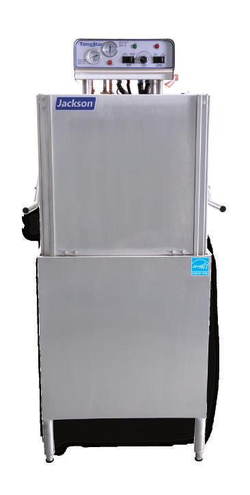


1 INSTALLATION, OPERATION, AND SERVICE MANUAL TEMPSTAR SERIES DOOR-TYPE DISHMACHINES TempStar Manual TEMPSTAR
2 WARRANTY REGISTRATION: MANUFACTURER'S LIMITED WARRANTY (APPLICABLE ONLY IN THE UNITED STATES AND CANADA) To register your Jackson Dishmachine s warranty go to or call Failure to register the Dishmachine will void the warranty. ONE YEAR LIMITED AND LABOR WARRANTY For a period of one (1) year from date of original installation of a new Jackson Dishmachine (but in no event to exceed eighteen (18) months from date of shipment from Jackson s factory), Jackson WWS, Inc. (Jackson) will repair or replace, at its discretion, any original part that proves defective in materials or workmanship at the time the Dishmachine was purchased; provided that (i) the Dishmachine has not been altered, (ii) the Dishmachine has been properly installed, maintained, and operated under normal use conditions and in accordance with the applicable installation, operation and service manual available on the Jackson website, and (iii) a warranty claim is reported to a Jackson Authorized Service Agency within the warranty period. This warranty includes replacement with Jackson specified genuine replacement parts, purchased directly from a Jackson Authorized Parts Distributor or Service Agency. Use of generic replacement parts may create a hazard and shall void this warranty. THIS WARRANTY DOES NOT APPLY OUTSIDE THE UNITED STATES AND CANADA. Jackson will pay the labor to repair or replace a defective original part as a part of the warranty, provided that a Jackson Authorized Service Agency performs the labor. Any repair or replacement work by anyone other than a Jackson Authorized Service Agency is the sole responsibility of the purchaser. Labor coverage is limited to regular hourly rates; Jackson will not pay overtime premiums or emergency service charges. Accessory components (such as table limit switches, pressure regulators, and drain water tempering kits) that are not installed by Jackson at the factory and are shipped with the Dishmachine carry only a (1) one year parts warranty. Labor to repair or replace these components is not included in the warranty or covered by Jackson. Booster heaters not manufactured by Jackson are not covered by this warranty, but are warranted by their respective manufacturers. This warranty is void if any defect or failure is a direct result from shipping, handling, fire, water, accident, alteration, modification, misuse, abuse, flood, acts of God, burglary, casualty, attempted repair by unauthorized persons, use of replacement parts not authorized by Jackson, improper installation, installation not in accordance with local electrical and plumbing codes, if the serial number has been removed or altered, if the Dishmachine is used for any purpose other than originally intended, or if the equipment is installed for residential use. Jackson does not authorize any other entity or person, including, without limitation, any entity or person who deals in Jackson s Dishmachines, to change this warranty or create any other obligation in connection with Jackson s Dishmachines. TRAVEL LIMITATIONS: Jackson limits warranty travel time to the customer site within 50 miles of the Jackson authorized service agents office and during regular business hours. Jackson will not pay for travel time and mileage that exceeds these limits, or any fees such as those for air or boat travel without prior authorization. REPLACEMENT WARRANTY: For a period of (90) ninety days from the date of installation by a Jackson Authorized Service Agency (but in no event to exceed (180) one-hundred-eighty days from the date of purchase from a Jackson Authorized Parts Distributor or Service Agency), Jackson will repair or replace, at its discretion, any Jackson genuine replacement parts that prove defective in materials or workmanship at the time the replacement parts were installed. This warranty does not include paying the labor to repair or replace the replacement part. This warranty is subject to all conditions, exclusions and limitations applicable to the Dishmachine.
3 MANUFACTURER'S LIMITED WARRANTY (CONT.) (APPLICABLE ONLY IN THE UNITED STATES AND CANADA) PRODUCT CHANGES: Jackson reserves the right to make changes in design and specification of any component of the Dishmachine as engineering or necessity requires. DISCLAIMER OF WARRANTIES: THERE ARE NO WARRANTIES, EXPRESSED OR IMPLIED, INCLUDING, WITHOUT LIMITATION, ANY IMPLIED WARRANTY OF FITNESS FOR A PARTICULAR PURPOSE OR MERCHANTABILITY, THAT ARE NOT SET FORTH HEREIN, OR THAT EXTEND BEYOND THE DURATION HEREOF. LIMITATION OF REMEDIES AND LIABILITIES: YOUR SOLE AND EXCLUSIVE REMEDY UNDER THIS LIMITED WARRANTY SHALL BE PRODUCT REPAIR OR REPLACEMENT AS PROVIDED HEREIN. UNDER NO CIRCUMSTANCES WILL JACKSON BE LIABLE FOR ANY INCIDENTAL OR CONSEQUENTIAL DAMAGES, OR FOR DAMAGES IN THE NATURE OF PENALTIES. JACKSON S LIABILITY ON ANY CLAIM OF ANY KIND WITH RESPECT TO THE GOODS OR SERVICES COVERED HEREUNDER SHALL IN NO CASE EXCEED THE PRICE OF THE GOODS OR SERVICES OR PART THEREOF WHICH GIVES RISE TO THE CLAIM. ITEMS NOT COVERED: THIS WARRANTY DOES NOT COVER (1) ADJUSTMENTS INCLUDING, BUT NOT LIMITED TO, TIMER CAMS, THERMOSTATS, DOORS, TANK HEATER ADJUSTMENTS OR CLUTCHES; (2) AIR FREIGHT OR OVERNIGHT FREIGHT; (3) ANY AMOUNT EXCEEDING ORIGINAL PURCHASE PRICE; (4) CLEANING OF DRAIN VALVES, GAS LINES, RINSE/WASH NOZZLES, STRAINERS, SCREENS, OR SPRAY PIPES; (5) CLEANING OR DELIMING OF THE DISHMACHINE OR ANY COMPONENT INCLUDING, BUT NOT LIMITED TO, WASH ARMS, RINSE ARMS AND STRAINERS; (6) CONDITIONS CAUSED BY THE USE OF INCORRECT (NON-COMMERCIAL) GRADE DETERGENTS; (7) CORROSION FROM CHEMICALS DISPENSED IN EXCESS OF RECOMMENDED CONCENTRATIONS; (8) COSMETIC DAMAGE, INCLUDING BUT NOT LIMITED TO, SCRATCHES, DENTS, CHIPS, AND OTHER DAMAGE TO THE DISHMACHINE FINISHES, UNLESS SUCH DAMAGE RESULTS FROM DEFECTS IN MATERIALS AND WORKMANSHIP AND IS REPORTED TO JACKSON WITHIN (30) THIRTY DAYS FROM THE DATE OF INSTALLATION; (9) DAMAGE CAUSED BY LABOR DISPUTE; (10) DAMAGES RESULTING FROM IMPROPER CONNECTION TO UTILITY SERVICE; (11) DAMAGES RESULTING FROM WATER CONDITIONS, INADEQUATE OR EXCESSIVE WATER PRESSURE, ACCIDENTS, ALTERATIONS, IMPROPER USE, ABUSE, HANDLING, OVERLOADS, TAMPERING, IMPROPER INSTALLATION OR FAILURE TO FOLLOW MAINTENANCE AND OPERATING PROCEDURES; (12) DISCOLORATION, RUST OR OXIDATION OF SURFACES RESULTING FROM CAUSTIC OR CORROSIVE ENVIRONMENTS, INCLUDING, BUT NOT LIMITED TO, HIGH SALT CONCENTRATIONS, HIGH MOISTURE OR HUMIDITY, OR EXPOSURE TO CHEMICALS; (13) ELECTRIC BOOSTERS, FEED LINES, FLEX HOSE, FUSES, GARBAGE DISPOSALS, OR GAS PILOTS; (14) EXCESSIVE LIME, MINERAL, OR ALKALINE BUILDUP; (15) EXPENSES DUE TO DISCONNECTION, DELIVERY, RETURN AND REINSTALLATION; (16) FAILURE OF ELECTRICAL COMPONENTS DUE TO CONNECTION OF CHEMICAL DISPENSING EQUIPMENT INSTALLED BY OTHERS; (17) FAILURE OF FACILITY WATER HEATER TO MAKE TEMPERATURE; (18) FAILURE TO MAINTAIN WATER HARDNESS BETWEEN.25 AND 2.0 GRAINS, PH BETWEEN 7.0 AND 8.5 AND TOTAL DISSOLVED SOLIDS BELOW 250 PPM; (19) FAILURE TO COMPLY WITH LOCAL ELECTRICAL BUILDING CODES; (20) LEAKS OR DAMAGE RESULTING FROM SUCH LEAKS CAUSED BY THE INSTALLER, INCLUDING THOSE AT MACHINE TABLE CONNECTIONS, OR BY CONNECTION OF CHEMICAL DISPENSING EQUIPMENT INSTALLED BY OTHERS; (21) OPENING OR CLOSING OF UTILITY SUPPLY VALVES OR SWITCHING OF ELECTRICAL SUPPLY CURRENT; (22) PERFORMANCE OF REGULAR MAINTENANCE AND CLEANING AS OUTLINED IN THE OPERATOR S GUIDE; (23) REMOVAL OR REINSTALLATION OF INACCESSIBLE DISHMACHINES OR BUILT-IN FIXTURES THAT INTERFERE WITH SERVICING, REMOVAL OR REPLACEMENT OF THE DISHMACHINE; (24) REPLACEMENT WEAR ITEMS INCLUDING, BUT NOT LIMITED TO, CURTAINS, DRAIN BALLS, DOOR GUIDES, GASKETS, O-RINGS, SEALS, SQUEEZE TUBES, AND BEARINGS; (25) RESIDENTIAL USE; (26) USE WITH UTILITY SERVICE OTHER THAN THAT DESIGNATED ON THE RATING PLATE.
4 REVISION HISTORY Revision Letter Revision Date Made by Applicable ECNs Details A ARL 8045 Release to Production. B ARL 8094 Added new NSF rating. C JC 8114 Removed NSF Rating from steam heated machine. D ARL 8104 Added information regarding electrical field conversion. E RLC N/A Added information about Fused Universal Timer pg. 19. F RLC 8252 Updated schematic and control box assembly for rotary switch/removed EnergyStar Logo. G RLC QOF NDB-219 Updated Jackson logo and company name. H MHH N/A Corrected part number for right false panel kit, pg. 43. Removed STOP warning page, pg. 3. I MHH 8287 New bearing and P/N on rinse arm assy, pg. 41. J KAP N/A Updated Drain Quench Image on pg. 45. Added Drain Quench Miscellaneous Parts on pg. 55. K KAP N/A Updated part number for O-ring and Diaphragm on pg. 39. P/N was replaced by P/N L KAP QOF-386 Removed regulator and added Y-Strainer to the assemblies on pgs. 4, 36, and 38. Paragraph content was changed on pg. 7. Changed the PSI flow on pg. 15 M KAP QOF-386 Updated wire colors on schematic pgs. 49, 50, 51, 52, and 53. N KAP N/A Inserted note pertaining to corner installation pg. 5. P KAP N/A Added VER Operating Capacities on pg. 2. Added Pressure Regulator Option Dimensions on pg. 5. Added VER Machine Dimensions on pg. 6. Added VER pipe line size on pg. 9. Added Door interlock items on pg. 23. Updated Tub and Tub Assembly Thermostats on pgs Added thermister to Rinse Tank Assembly on pg. 30. Added VER Plumbing pgs. 41 and 42. Added VER and Energy Recovery Assembly pg. 46. Updated Schematic pgs. 54 and 55. Added Solid State BB/LT Schematic on page 58 and 60. Q KAP N/A Updated Schematic on pgs. 65 and KAP N/A Updated P/N for item #5 on pg KAP N/A Updated P/N for solenoid valve on pg. 40. Changed P/N from to R JH N/A Corrected P/N for item #33 on pg. 34. S JH N/A Added delime instructions. T JH QOF-386 Changed item 12 on pg. 35 to Added and to view (pg. 31) and parts list (pg. 32). iv
5 REVISION HISTORY Revision Letter Revision Date U JH N/A V JH Made by Applicable ECNs Details Added view showing dimensions for the notch cut into table on corner installations to pg. 4. Corrected total amps and typical electrical circuit for 230 V, 50 Hz, 1 Phase LT/NB machines on pg. 7 to 35 A and 40 A, respectively. Corrected P/N for item 6 on pgs. 36 and 39. Changed item 19 to item 17 in Tube Length Chart on pg. 51. Changed valve (item 15) view and P/N to on pgs. 51 and 52. Changed valve (item 7) view and P/N to on pg. 53. Removed views that showed pressure regulator in certain locations. Created Plumbing Options, pg. 54, with the pressure regulator and arrestor as options. Added wash arm end-cap as item #21 to pg. 58. Added external device wiring instructions. Added instructions for programming new exhaust fan timer. Added rinse arm bearing replacement instructions. Updated schematics. Changed name of delime switch throughout from NORMAL/DELIME to AUTO/MANUAL. Updated Delime Instructions and added instructions for low-temp machine. Added water level probe cleaning to the Shutdown and Cleaning section. Updated to new manual format. Audited and corrected all P/Ns in the manual. Changed steam pressure to PSI on pg. 5. Updated electrical requirements, pgs Added links to exhaust fan timer instructions to pg. 9. Added Chemical Connections section to pg. 10. Added Motor Rotation section to pg. 11. Added new exhaust fan timer to pgs. 22 and 26. Added fuses to pg. 24. Changed P/N for contactor, item #4 on pg. 25. Replaced thermostat and components with solid state thermostat and components pgs Added page for new rinse tank on pg. 38. Updated P/Ns on pg. 39. Updated motor P/Ns on pgs Updated heater P/Ns on pgs Added new phase conversion kit P/N to pg. 44. Updated plumbing to new rinse tank plumbing on pgs Updated VER plumbing to new rinse tank plumbing on pg. 50. Changed rinse arm bearing assembly on pgs Changed rinse arm bearing kit P/N on pg. 53. Updated pg with new view and parts list. Added list of applicable kits to pg. 59. Added new rinse tank schematics and updated others. v
6 NOMENCLATURE TempStar Door-type dishmachine; ENERGY STAR qualified, electrically-heated, high-temp, hot-water sanitizing, with booster heater. TempStar LT Door-type dishmachine; electrically-heated, low-temp, chemical-sanitizing, with no rinse booster. TempStar NB Door-type dishmachine; electrically-heated, high-temp, hot-water sanitizing, with no rinse booster. TempStar S Door-type dishmachine; steam-heated, high-temp, hot-water sanitizing. TempStar VER Door-type dishmachine; electrically-heated, high-temp, hot-water sanitizing, with booster heater and ventless energy recovery system. The manufacturer provides technical support for all of the dishmachines detailed in this manual. We strongly recommend that you refer to this manual before making a call to our technical support staff. Please have this manual open when you call so that our staff can refer you, if necessary, to the proper page. Technical support is not available on holidays. Contact technical support tollfree at Technical support is available for service personnel only. vi
7 TABLE OF CONTENTS GUIDES Symbols... 1 Abbreviations & Acronyms... 1 SPECIFICATIONS TempStar/LT/NB/S Dimensions... 2 VER Dimensions... 3 Table Dimensions... 4 Operating Parameters... 5 Electrical Requirements... 6 INSTALLATION Installation Instructions... 8 Inspection...8 Unpacking...8 Leveling...8 Plumbing...8 Water Supply Connection...8 Steam Line Connection...9 Pressure Regulator...9 Shock Absorber...9 Connecting the Drain Line...9 Exhaust Fan Timer...9 Chemical Connections...10 Plumbing Check...10 Electrical Power Connections Motor Rotation Voltage Check...12 Surrounding Area...12 Temperature Setpoints...12 False Panel/Corner Install...12 OPERATION Operating Instructions Preparation Power Up Filling the Wash Tub Ware Preparation Daily Machine Preparation Warm-Up Cycles Washing a Rack of Ware Operational Inspection Shutdown & Cleaning VER Coil Cleaning vii
8 TABLE OF CONTENTS OPERATION Detergent Control Deliming MAINTENANCE Preventative Maintenance TROUBLESHOOTING Common Problems Control Box Hood Door & Arm Tub Steam Tub Frame Rinse Tank Steam Coil Motors Heaters Plumbing Plumbing - NB Plumbing - Steam Plumbing - VER Plumbing Options Wash & Rinse Assemblies VER System VER Door Interlock VER Door Interlock Override V Machine Transformer Mounting Box Kits SCHEMATICS TempStar/VER, V, New Rinse Tank TempStar/VER, 460 V, New Rinse Tank TempStar/VER, V, Old Rinse Tank TempStar/VER, 460 V, Old Rinse Tank NB, V NB, 460 V Steam, V SDI Options viii
9 GUIDES GUIDES SYMBOLS! WARNING - risk of injury to personnel.! CAUTION - risk of damage to equipment. - risk of electrical shock. - caustic chemicals. i - reference data plate. - lockout electrical power. NOTICE - important note. - instructions hyperlink. ABBREVIATIONS & ACRONYMS ANSI - American National Standards Institute Btu/Hr - British Thermal Units per Hour CFM - Cubic Feet per Minute GHT - Garden Hose Thread GPH - Gallons per Hour GPM - Gallons per Minute GPG - Grains per Gallon HP - Horsepower Hz - Hertz ID - Inside Diameter kw - Kilowatts MCA - Minimum Circuit Ampacity MOP - Maximum Overcurrent Protection NFPA - National Fire Protection Association NPT - National Pipe Thread OD - Outside Diameter PRV - Pressure Regulating Valve PSI - Pounds per Square Inch V - Volts 1
10 SPECIFICATIONS TEMPSTAR/LT/NB/S DIMENSIONS U LEGEND B A - Water Inlet (1/2 NPT) B - Electrical Connection Point C - Drain (1 1/2 NPT) D - Optional Steam Connection (3/4 NPT) can be increased 2" using the machine's adjustable feet. U A B B C C D D C 2
11 SPECIFICATIONS B (134mm) (785mm) 4 (102mm) MINIMUM VER DIMENSIONS LEGEND A - Drain (1 1/2" NPT) B - Water Inlet (3/4" NPT) C - Electrical Connection Point can be increased 2" using the machine's adjustable feet (641mm) 32 (813mm) B 17 (432mm) 3 (79mm) A C (616mm) C AC 82 (2083mm) (438mm) CLEARANCE 77 (1956mm) (1468mm) 60 (1527mm) A (120mm) (335mm) A (394mm) 3
12 SPECIFICATIONS TABLE DIMENSIONS CORNER INSTALLATION For corner install instructions: CORNER INSTALLATION 4 (102 mm) MIN ALIGN WITH TABLE - DISTANCE CAN VARY 30 (762 mm) 8 7/16 (214 mm) 20 1/2 (521 mm) OPENING 4 (102 mm) MIN ALIGN WITH TABLE - DISTANCE CAN VARY Distance from wall to rear rack rail. Control Panel Distance from wall to right rack rail. 8 7/16 (214 mm) 1 1/4 [32 mm] 1 3/8 [35 mm] 20 1/2 [521 mm] OPENING STRAIGHT-THROUGH INSTALLATION STRAIGHT-THROUGH INSTALLATION 4 (102 mm) MIN ALIGN WITH TABLE - DISTANCE CAN VARY 30 (762 mm) 8 7/16 (214 mm) 20 1/2 (521 mm) OPENING 20 1/2 (521 mm) OPENING Distance from wall to rear rack rail. Control Panel 4
13 SPECIFICATIONS PERFORMANCE/CAPABILITIES Operating Capacity: TempStar/NB/S Racks per Hour 58 Dishes per Hour 1450 Glasses per Hour 2088 LT Racks per Hour 50 Dishes per Hour 1250 Glasses per Hour 1800 VER Racks per Hour 39 Dishes per Hour 975 Glasses per Hour 1404 Minimum Operating Cycle (seconds): TempStar/NB/S Wash Time 40 Rinse Time 13 Dwell Time 4 Total Cycle Time 57 LT Wash Time 45 Rinse Time 11 Dwell Time 10 Total Cycle Time 66 VER Wash Time 40 Rinse Time 13 Dwell Time 4 Condensate Removal 30 Total Cycle Time 87 Tank Capacity (Gallons/Liters): Wash Tank 8.0/30.3 Rinse Tank 2.0/7.6 Steam Requirements: Coil Size 3/4" Steam Flow Pressure (PSI) Consumption at 15 PSI (lbs/hr) 45 OPERATING PARAMETERS WATER REQUIREMENTS TempStar/VER Minimum Wash Temperature ( F/ C) 150/66 Minimum Rinse Temperature ( F/ C) 180/83 Inlet Water Temperature: 12 kw Rinse Heater ( F/ C) 140/60 14 kw Rinse Heater ( F/ C) 110/44 VER ( F/ C) 40-90/ Flow Pressure (PSI) 10 ± 2 Water Line Size 1/2 Water Line Size (VER) 3/4" Drain Line Size 1 1/2 LT Minimum Wash Temperature ( F/ C) 130/55 Minimum Rinse Temperature ( F/ C) 130/55 Inlet Water Temperature ( F/ C) 130/55 Flow Pressure (PSI) 10 ± 2 Water Line Size 3/4 Drain Line Size 1 1/2 Minimum Chlorine Required (PPM) 50 NB Minimum Wash Temperature ( F/ C) 150/66 Minimum Rinse Temperature ( F/ C) 180/83 Inlet Water Temperature ( F/ C) 180/83 Flow Pressure (PSI) 10 ± 2 Water Line Size 1/2 Drain Line Size 1 1/2 S Minimum Wash Temperature ( F/ C) 150/66 Minimum Rinse Temperature ( F/ C) 180/83 Inlet Water Temperature ( F/ C) 180/83 Flow Pressure (PSI) 10 ± 2 Water Line Size 3/4 Drain Line Size 1 1/2 ENERGY SPECIFICATIONS VER Latent Heat Sensible Heat 4678 Btu/Hr 5190 Btu/Hr NOTICE i Always refer to the machine data plate for specific electrical and water requirements. The material provided on this page is for reference only and is subject to change without notice. 5
14 SPECIFICATIONS ELECTRICAL REQUIREMENTS Local codes may require more stringent protection than what is displayed here and on the data plate. Always verify with your electrical service contractor that your circuit protection is adequate and meets all applicable national and local codes. Numbers in this manual are for reference and may change without notice. i NOTICE On three-phase machines, imbalanced wild leg goes to L3. Also see the Motor Rotation section. TEMPSTAR 70 Rise (14 kw) & TEMPSTAR VER Wash Volts Phase Freq Motor Wash Heater Rinse Heater Total Load MCA MOP Hz 5.0 A 19.7 A 50.6 A 75.3 A 76.6 A 80.0 A Hz 5.0 A 21.8 A 55.9 A 82.7 A 84.0 A 90.0 A Hz 5.0 A 11.4 A 29.2 A 45.6 A 46.9 A 50.0 A Hz 5.0 A 12.6 A 32.3 A 49.9 A 51.2 A 55.0 A Hz 1.8 A 6.3 A 16.1 A 24.2 A 24.7 A 30.0 A i TEMPSTAR 40 Rise (12 kw) Volts Phase Freq Wash Motor Wash Heater Rinse Heater Total Load MCA MOP Hz 5.0 A 19.7 A 43.3 A 68.0 A 69.3 A 70.0 A Hz 5.0 A 21.8 A 47.9 A 74.7 A 76.0 A 80.0 A Hz 5.0 A 11.4 A 25.0 A 41.4 A 42.7 A 45.0 A Hz 5.0 A 12.6 A 27.7 A 45.3 A 46.6 A 50.0 A Hz 1.8 A 6.3 A 13.8 A 21.9 A 22.4 A 25.0 A 6
15 SPECIFICATIONS ELECTRICAL REQUIREMENTS Local codes may require more stringent protection than what is displayed here and on the data plate. Always verify with your electrical service contractor that your circuit protection is adequate and meets all applicable national and local codes. Numbers in this manual are for reference and may change without notice. i NOTICE On three-phase machines, imbalanced wild leg goes to L3. Also see the Motor Rotation section. TEMPSTAR LT/NB Volts Phase Freq Wash Motor Wash Heater Rinse Heater Total Load MCA MOP Hz 5.0 A 19.7 A N/A 24.7 A 26.0 A 30.0 A Hz 5.0 A 21.8 A N/A 26.8 A 28.1 A 30.0 A Hz 5.0 A 11.4 A N/A 16.4 A 17.7 A 20.0 A Hz 5.0 A 12.6 A N/A 17.6 A 18.9 A 20.0 A Hz 1.8 A 6.3 A N/A 8.1 A 8.6 A 15.0 A i TEMPSTAR S Volts Phase Freq Wash Motor Wash Heater Rinse Heater Total Load MCA MOP Hz 5.0 A N/A N/A 5.0 A 6.3 A 15.0 A Hz 5.0 A N/A N/A 5.0 A 6.3 A 15.0 A Hz 5.0 A N/A N/A 5.0 A 6.3 A 15.0 A Hz 5.0 A N/A N/A 5.0 A 6.3 A 15.0 A Hz 1.8 A N/A N/A 1.8 A 2.3 A 15.0 A 7
16 INSTALLATION INSPECTION Do not throw away packaging if damage is evident! INSTRUCTIONS Before installing the machine, check the packaging and machine for damage. If the packaging is damaged, the machine might also be damaged. If there is damage to both packaging and machine, do not throw away the packaging. The machine has been inspected and packed at the factory and is expected to arrive to you in new, undamaged condition. However, rough handling by carriers or others might result in damage to the machine while in transit. If so, do not return the machine to the manufacturer. Instead, contact the carrier and ask them to send a representative to the site to inspect the damage and complete an inspection report. You must contact the carrier and the dealer that sold you the machine within 48 hours of receiving the machine. UNPACKING While unpacking the machine, ensure that there are no missing parts. If an item is missing, contact the manufacturer immediately. LEVELING The machine must be level in its operating location to prevent damage to the machine during operation and to ensure the best results. The machine comes with four adjustable bullet feet, which can be turned using a pair of channel locks (or by hand if the machine can be raised safely). Ensure that the machine is level from side-to-side and front-toback before making any connections. PLUMBING The plumber MUST flush the incoming water line! A water hardness test MUST be performed. Plumbing connections must comply with all applicable local, state, and national plumbing codes. The plumber is responsible for ensuring that the incoming water line is thoroughly flushed before connecting it to any component of the machine. It is very important to remove all foreign debris from the water line that might potentially get trapped in the valves or cause an obstruction. Any valves that are fouled as a result of foreign matter left in the water line and any expenses resulting from this fouling are not the responsibility of the manufacturer. A water hardness test must be performed to determine if a water treatment system needs to be installed. WATER SUPPLY CONNECTION: WATER HARDNESS GREATER THAN 3 GPG If water hardness tests at greater than 3 GPG, install the Scaltrol Water Treatment system (see the Plumbing Options page) into the water line before the machine s incoming water connection point. A water shut-off valve should be installed to allow access for service. WATER SUPPLY CONNECTION: WATER HARDNESS LESS THAN 3 GPG If water hardness tests at less than 3 GPG, install the water supply line directly to the machine s incoming water connection point. A water shut-off valve should be installed to allow access for service. 8

. The PRV comes standard on the TempStar VER but ships inside the machine. Click here for install instructions.")
17 INSTALLATION INSTRUCTIONS STEAM LINE CONNECTION The steam machines come with lines to connect the source steam. Connect all steam lines to the machine as all applicable codes provide. See machine data plate for information concerning steam flow pressure. Click here or on the instructions icon for the Steam Booster manual. PRESSURE REGULATOR The manufacturer recommends the installation of a pressure regulating valve (PRV) in the incoming water line to ensure proper flowrate at all times and offers these devices as options (see the Plumbing Options page). The PRV comes standard on the TempStar VER but ships inside the machine. Click here for install instructions. Do not confuse static pressure with flow pressure. Static pressure is the line pressure in a no flow condition (all valves and services are closed). Flow pressure is the pressure in the fill line when the fill valve is opened during the cycle. SHOCK ABSORBER The manufacturer also recommends the installation of a shock absorber in the incoming water line and offers these devices as options (see the Plumbing Options page). This prevents line hammer/hydraulic shock induced by the solenoid valve as it operates from causing damage to the equipment. CONNECTING THE DRAIN LINE The machine's drain is a gravity-discharge drain. All piping from the 1 1/2 NPT connection on the wash tank must be pitched (1/4 per foot) to the floor or sink drain. All piping from the machine to the drain must be a minimum 1 1/2 NPT and must not be reduced. There must also be an air-gap between the machine drain line and the floor sink or drain. If a grease trap is required by code, it should have a flow capacity of 5 GPM. EXHAUST FAN TIMER Determine which exhaust fan timer is on the machine (located in the control box) and click the instructions icon below that timer to access programming instructions. 9

18 INSTALLATION INSTRUCTIONS CHEMICAL CONNECTIONS Detergent Connect detergent by removing the bulkhead fitting on the back of the machine and replacing it with the appropriate dispensing equipment. Chemical connections should be made by the chemical supplier. Using deionized water or other aggressive fluids will result in corrosion and failure of components and will void the warranty.! WARNING WARNING! Some of the chemicals used in dishwashing may cause chemical burns if they come in contact with skin. Wear protective gear when handling these chemicals. If any skin comes in contact with these chemicals, immediately follow the instructions provided with the chemicals for treatment. Detergent Probe Installs Here Rinse-aid and Sanitizer Connect rinse-aid (and sanitizer, if an LT machine) by removing the brass plug at the base of the rinse injector and replacing it with the appropriate dispensing equipment. See "Plumbing - VER" page for a depiction of the VER rinse injector. Sanitizer (LT Only) Rinse-aid Dispenser Electrical Connections The electrical connections for chemical dispensers are made on a fuse block inside the control box. Click here for a depiction of the fuse block and connection locations. PLUMBING CHECK Slowly turn on the water supply to the machine after the incoming fill line and drain line have been installed. Check for any leaks and repair as required. All leaks must be repaired before operating the machine. 10
19 INSTALLATION INSTRUCTIONS ELECTRICAL POWER CONNECTIONS Electrical and grounding conductors must comply with the applicable portions of the National Electric Code ANSI/NFPA 70 (latest edition) and/or other electrical codes. The data plate is located on the right side of the machine. Refer to the data plate for machine operating requirements, machine voltage, total amperage, and serial number. Disconnect electrical power supplies and lockout/tagout in accordance with appropriate procedures and codes at the disconnect switch. 1. Open the control box by using a phillips screwdriver to remove the four screws on the front cover of the control box. 2. Install 3/4 conduit into the pre-punched holes in the back of the control box. 3. Route power wires and connect to power block and grounding lug. 4. Install the service wires (L3 for 3-Phase only) to the appropriate terminals as they are marked on the terminal block. If necessary, see "Heaters" page for phase conversion kit. L3 3Φ L2 L1 Ground NOTICE Imbalanced wild leg goes to L3.! CAUTION 5. Install the grounding wire into the lug provided. 6. Tighten the connections. NOTICE DE-OX or similar anti-oxidation agent should be used on all power connections. CAUTION! Improperly connecting external devices can cause damage to the machine and/or electrical infrastructure! Click here for a wiring guide. MOTOR ROTATION! CAUTION CAUTION! On 3-Phase machines only, correct pump motor rotation must be verified before operation! i On 3-Phase machines only, correct pump motor rotation must be verified before the machine is operated. Failure to do so can result in damage to the machine and components. 1. Follow the "Filling the Wash Tub" section. 2. Locate the wash pump motor and identify the arrow decal which shows the correct motor rotation (if no decal is present, correct rotation is away from the pump volute). Pump Volute Impeller 3. Flip the mode switch to "MANUAL" and start the machine. 4. Observe the rotation of impeller and quickly stop the machine. 5. If rotation is incorrect, disconnect electrical power and reverse the L1 and L2 connections at terminal block shown in the section above. 11
20 INSTALLATION INSTRUCTIONS VOLTAGE CHECK i Ensure that the power switch is in the "OFF" position and apply power to machine. Check the incoming power at the terminal block and ensure it corresponds with the voltage listed on the data plate. If not, contact a qualified service agency to examine the problem. Do not run the machine if voltage is too high or too low. Shut off the service breaker and advise all proper personnel of the location of the breaker and any problems. Replace the control box cover and tighten-down the screws. SURROUNDING AREA This is a commercial dishmachine and reaches temperatures that can exceed those generated by a residential machine. Surrounding countertops, cabinets, flooring material, and subflooring material must be designed and/or selected with these higher temperatures in mind. NOTICE Any damage to surrounding area caused by heat/moisture to materials that are not recommended for higher temperatures will not be covered under warranty or by the manufacturer. TEMPERATURE SETPOINTS The temperature setpoints on this machine have been set at the factory. They should only be adjusted by an authorized service agent. FALSE PANEL/ CORNER INSTALL The manufacturer offers an optional False Panel Kit for corner installations. See the Kits page for kit part number. Click here for false panel/corner install instructions. 12


21 OPERATION OPERATING INSTRUCTIONS PREPARATION Before operating the machine, verify the following: 1. The tank is clean and free of debris. 2. The wash arms, rinse arms, sump strainer, and scrap screen are all installed correctly. 3. The standpipe is installed. Wash & Rinse Arms, Scrap Screen Sump Strainer Standpipe POWER UP To energize the machine, turn on the power at the service breaker. The voltage should have been previously verified as being correct. If not, the voltage will have to be verified. FILLING THE WASH TUB Ensure that the mode switch is in the "AUTO" position, and place the power switch into the "ON" position. The machine will fill automatically and shut-off when the appropriate level is reached (just below the scrap screen). The wash tub must be completely filled before operating the wash pump to prevent damage to components. Once the wash tub is filled, the machine is ready for operation. WARE PREPARATION Proper ware preparation will help ensure good results and fewer re-washes. If not prepared properly, ware might not come out clean and the efficiency of the machine will be reduced. Putting unscraped dishes into the machine affects its performance, so scraps should always be removed from ware before being loaded into a rack. Pre-rinsing and pre-soaking are good ideas, especially for silverware and casserole dishes. Place cups and glasses upside-down in racks so they don't hold water during the cycle. The machine sanitizes as well as cleans. To do this, ware must be properly prepared before being placed in the machine. DAILY MACHINE PREPARATION Refer to the Preparation section and follow the instructions there. Afterward, ensure that chemicals are supplied to the machine. If not, contact your chemical supplier. 13

22 OPERATION WARM-UP CYCLES OPERATING INSTRUCTIONS For the first operation of each day, it might be necessary to run the machine through three cycles to ensure that all of the cold water is out of the system and to verify that the machine is operating correctly. To cycle the machine, ensure that the power is on and that the tub has filled to the correct level. Lift and close the door and the cycle light will illuminate. The machine will start, run through the cycle, and shut-off automatically. Repeat this two more times. The machine is now ready. WASHING A RACK OF WARE To wash a rack, open the door completely (avoiding hot water that might drip from the door) and slide the rack into the machine. Close the door and the machine will start automatically. Once the cycle is complete, open the door and remove the rack of clean ware. Replace with a rack of soiled ware and close the door. Repeat this process. OPERATIONAL INSPECTION Based on use, the scrap screen might become clogged with soil and debris as the workday progresses. Operators should regularly inspect the scrap screen to ensure it has not become clogged. If clogged, it will reduce the washing capability of the machine. Instruct operators to clean-out the scrap screen at regular intervals or as required by workload. Do NOT beat strainers to remove debris. SHUTDOWN & CLEANING 1. Turn machine off by flipping the power switch to OFF.! WARNING 2. Open the door and allow steam/heat to escape. 3. Remove the standpipe and allow the tub to drain. WARNING! Wash tank water will be hot! 14


23 OPERATION SHUTDOWN & CLEANING OPERATING INSTRUCTIONS 4. Remove the sump strainer and scrap screen. 5. Use a hand-scraper to scrape foodsoil into a trash basket. 6. Rinse with pre-rinse hose and replace. 7. Remove all wash and rinse arms. 8. Remove the end-caps from the arms. 9. Clean nozzles with a brush. 15


24 OPERATION OPERATING INSTRUCTIONS SHUTDOWN & CLEANING 10. Use a small wire or toothpick to remove remaining debris or lime deposits from the nozzles. 11. Flush the arms with water. 12. Replace end-caps and ensure they have been tightened. 13. Spray or wipe out interior of the machine. 14. Replace wash and rinse arms. 15. Ensure sump strainer and scrap screen are clean and securely in place. 16. Use stainless steel polish to clean and protect outside of machine. VER COIL CLEANING The coil on the VER machine must be inspected periodically. If the coil is greasy, dirty, or there is scale build-up, click here for cleaning instructions. 16
25 OPERATION DETERGENT CONTROL DETERGENT CONTROL Detergent usage and water hardness are two factors that contribute greatly to how efficiently this machine will operate. Using detergent in the proper amount can become a source of substantial savings. A qualified water treatment specialist can determine what is needed for maximum efficiency from the detergent. See "Water Supply Connection" section for more information on water treatment. 1. Hard water greatly affects the performance of the machine, causing the amount of detergent required for washing to increase. If the machine is installed in an area with hard water, the manufacturer recommends the installation of water treatment equipment. 2. Deposited solids from hard water can cause spotting that will not be removed with a drying agent. Treated water will reduce this occurence. 3. Treated water might not be suitable for use in other areas of operation and it might be necessary to install a water treatment system for the water going to the machine only. Discuss this option with a qualified water treatment specialist. 4. Machine operators should be properly trained on how much detergent is to be used per cycle. Meet with a water treatment specialist and detergent vendor to discuss a complete training program for operators. 5. These machines require that chemicals be provided for proper operation and sanitization and require the installation of third-party chemical feeders to introduce these chemicals to the machine. Contact a chemical supplier with any questions. i 6. Water temperature is an important factor in ensuring that the machine functions properly. The machine's data plate details what the minimum temperatures must be for the incoming water supply, the wash tank, and the rinse tank. If minimum requirements are not met, there is a possibility that dishes will not be clean or sanitized. 7. Instruct machine operators to observe the required temperatures and to report when they fall below the minimum allowed. A loss of temperature can indicate a larger problem. 17

26 OPERATION DELIMING DELIMING To delime the machine, follow the steps below. The tank capacities of the machine can be found on the Operating Parameters page of this manual. 1. Remove rinse arms and place in sink with deliming solution. 2. Disconnect or turn off chemical feeder pumps. 3. Add deliming solution per chemical supplier s instructions. 4. Close the door and turn the machine on in "MANUAL" mode. 5. Run the machine for the length of time recommended by the chemical supplier. 6. Flip the mode switch to "AUTO" to shut the machine off. 7. Open the door and step away for five minutes. 8. Inspect the inside of the machine. If the machine is not delimed, run again. 9. When clean, drain and re-fill the machine. 10. Run two cycles in "AUTO" to remove residual deliming solution. 11. Drain and re-fill the machine. 12. Flush rinse arms with water and replace. Mode Switch Power Switch! CAUTION CAUTION! This equipment is not recommended for use with deionized water or other aggressive fluids. Using deionized water or other aggressive fluids will result in corrosion and failure of components and will void the warranty. 18
27 MAINTENANCE PREVENTATIVE MAINTENANCE PREVENTATIVE MAINTENANCE! WARNING The manufacturer highly recommends that any maintenance and repairs not specifically discussed in this manual be performed only by qualified service personnel. WARNING! Unqualified personnel performing maintenance on the machine may void the warranty, lead to larger problems, or cause harm to the operator. Following the operating and cleaning instructions in this manual will result in the most efficient results from the machine. As a reminder, here are some steps to take to ensure the machine is being used the way it was designed to work: i! CAUTION CAUTION! Do NOT beat strainers to remove debris! 1. Ensure the water temperatures match those listed on the machine data plate. A loss of temperature can indicate a larger problem. 2. Ensure all strainers are clean and securely in place before operating the machine. When cleaning out strainers, do NOT beat them on waste cans. Wipe out strainers with a rag and rinse with water if necessary. Use a toothpick to dislodge any stubborn debris. 3. Ensure all wash and rinse arms are secure in the machine before operating. 4. Ensure the standpipe is in position before operating. 5. Remove as much soil from dishes by hand as possible before loading into racks. 6. Do not overfill racks. 7. Ensure glasses are placed upside-down in the rack. 8. Ensure all chemicals being injected into the machine are at the correct concentrations. 9. Clean the machine at the end of every day/shift per the Shutdown and Cleaning section of this manual. 10. Follow all safety procedures, whether listed in this manual or put forth by local, state, or national codes/regulations. 19
28 TROUBLESHOOTING COMMON PROBLEMS! WARNING WARNING! Inspection, testing, and repair of electrical equipment should only be performed by a qualified service technician. Many of the tests require that the machine have power to it and live electrical components be exposed. USE EXTREME CAUTION WHEN TESTING THE MACHINE. PROBLEM POSSIBLE CAUSE REMEDY Machine will not fill after the door is closed. Power ON light is illuminated. Machine will not fill after the door is closed. Power ON light is NOT illuminated. Machine will not run after the door is closed. Power ON light is illuminated and the machine is filling. Machine runs continuously in the wash cycle. Wash or rinse heater does not work. Machine fills slowly and/or the rinse is weak. Rinse water not reaching required temperature. 1. Faulty rinse solenoid valve. 2. Faulty door switch. 3. Fouled/faulty high-level probe. 1. Service breaker tripped. 2. Machine not connected to power source. 3. Faulty power source. 1. Timer is faulty. 2. Wash motor faulty/damaged. 3. Wash motor contactor faulty. 1. Machine is in Delime mode. 2. Timer motor is faulty. 3. Cam timer jammed by obstruction. 1. Faulty heater element. 2. Faulty heater contactor. 3. Misadjusted/faulty thermostat(s). 1. Clogged or obstructed rinse arms. 2. Low incoming water pressure. 3. Y-strainer is clogged. 1. Faulty rinse heater. 2. Mis-adjusted/faulty thermostat(s). 3. Rinse thermometer is defective. 1. Repair or replace valve as required. 2. Verify the wiring of the switch; if correct, replace the switch. 3. Clean probe if fouled. If clean and still not working, replace. 1. Reset. If the breaker trips again, contact an electrician to verify the amp draw of the machine. 2. Verify the machine has been properly connected to the power source. 3. Verify the wiring of the switch; if correct, replace switch. 1. Verify the timer is receiving power. If so, replace the timer assembly. 2. Verify the wash motor is getting power. If so, replace the motor. 3. Check for continuity; if contacts are open, replace the contactor. 1. Flip mode switch to "AUTO." 2. Verify the timer is rotating. If not, verify the motor is receiving power. If so, replace the motor and/or timer assembly. 3. Remove obstruction. 1. Check element for continuity; if open, replace the heater. 2. Replace the contactor. 3. Verify operation and setting of thermostats, replace if necessary. 1. Remove and clean the rinse arms. 2. Adjust the water pressure regulator to ensure there is 10 ± 2 PSI flow. 3. Clean out the Y-strainer. 1. Check element for continuity; if open, replace heater. 2. Verify operation and setting of thermostats, replace if necessary. 3. Replace thermometer. 20
29 TROUBLESHOOTING COMMON PROBLEMS! WARNING WARNING! Inspection, testing, and repair of electrical equipment should only be performed by a qualified service technician. Many of the tests require that the machine have power to it and live electrical components be exposed. USE EXTREME CAUTION WHEN TESTING THE MACHINE. PROBLEM POSSIBLE CAUSE REMEDY Machine doesn t drain when power 1. Drain clogged. 1. Remove obstruction. switch is flipped to 2. Standpipe not removed before 2. Remove standpipe and run drain cycle again. draining. "OFF." Incorrect water pressure displayed during Fill or Rinse modes. 1. Water turned off. 1. Turn water on. Wash water is not reaching required temperature. 1. Faulty wash heater. 2. Misadjusted/faulty thermostat(s). 3. Wash thermometer is defective. 1. Check element for continuity; if open, replace the heater. 2. Verify operation and setting of thermostats, replace if necessary. 3. Replace thermometer. Door will not close completely. Water leaks at the wash pump. Will not rinse during autocycle. Dishes are not coming clean. 1. Improper spring tension. 2. Obstruction in door channel. 3. Door panels are not square with frame. 1. Wash pump seal defective. 2. Petcock or pump drain (if equipped) not shut/tight. 3. Loose hoses (hose clamps) on the wash pump. 1. Defective rinse solenoid. 2. Faulty timer. 3. No water to the machine. 1. Machine temperatures are not up to the minimum requirements. 2. No detergent/too much detergent. 1. Adjust spring tension as required by loosening (not removing) spring bolt nuts and adjusting the tension. Tighten nuts back when done. 2. Remove the obstruction. 3. Adjust the frame to accommodate the door panels. 1. Replace the seal. 2. Close or tighten. 3. Tighten the hose clamps. 1. Repair or replace the rinse solenoid as required. 2. Replace timer. 3. Verify there is water at 10 ± 2 PSI connected to the machine. 1. Verify incoming water, rinse water, and wash water match the required temperatures as listed on the machine data plate. 2. Adjust detergent concentration as required for the amount of water held by the machine. 21
30 CONTROL BOX
31 CONTROL BOX
32 CONTROL BOX Fuses 208/230 V or 460 V WARNING: DISCONNECT POWER TO MACHINE BEFORE SERVICING EXHAUST FAN CONSTANT VOLTAGE RINSE-AID DISPENSER DETERGENT CONTROL CONNECTION CONNECTION DISPENSER CONNECTION MAXIMUM LOAD LIVE WHEN MACHINE LIVE WHEN RINSE LIVE WHEN WASH 1 AMP, 240/120 VAC POWER SWITCH IS ON VALVE IS OPEN PUMP MOTOR IS ON INPUT L1 OUTPUT TO FUSE: 3 AMP SLOW-ACTING FUSE: 3 AMP SLOW-ACTING FUSE: 3 AMP SLOW-ACTING (EXTERNAL) EXT. RELAY L1 OUT L2 OUT L1 OUT L2 OUT L1 OUT L2 OUT WARNING: DISCONNECT POWER TO MACHINE BEFORE SERVICING EXHAUST FAN CONSTANT VOLTAGE RINSE-AID DISPENSER DETERGENT CONTROL CONNECTION CONNECTION DISPENSER CONNECTION MAXIMUM LOAD LIVE WHEN MACHINE LIVE WHEN RINSE LIVE WHEN WASH 1 AMP, 240/120 VAC POWER SWITCH IS ON VALVE IS OPEN PUMP MOTOR IS ON INPUT L1 OUTPUT TO FUSE: 200 ma SLOW-ACTING FUSE: 200 ma SLOW-ACTING FUSE: 200 ma SLOW-ACTING (EXTERNAL) EXT. RELAY 240 VAC OUT 240 VAC OUT 240 VAC OUT Fuse,1 A, Fast-acting Littelfuse P/N HXP Qty - 2 (2 per output) Fuse, 3 A, Slow-acting Littelfuse P/N HXP Qty - 6 (2 per output) Fuse,1 A, Fast-acting Littelfuse P/N HXP Qty - 2 (2 per output) Fuse, 200 ma, Slow-acting Littelfuse P/N HXP Qty - 6 (2 per output)
33 CONTROL BOX ITEM QTY DESCRIPTION PART NUMBER 1 1 Control Box Weldment Timer Bracket Locknut, Contactor, 4-Pole Terminal Block Locknut, Contactor, Wash Motor Relay a 1 Relay, (415 V, 3 PH, 5 Wire Only) Light, Green Light, Red Temperature Gauge, Temperature Gauge, Light, Yellow Decal, Wash 150 F Min Decal, Rinse 180 F Min Ground Lug Bracket, Liquid Level Control Board Liquid Level Control Board Tricnut, Screw, 6-32 x 5/ Plug, 1/ Grommet, 7/8 Split Bushing Snap Clamp, Hose 1/4" - 1/3" Decal, Warning-Disconnect Power Cover, Top Mount Control Box Decal, Control Box Lockwasher, Int. Tooth # Screw, x 3/8 Phillips Truss Head Decal, Copper Conductors
34 CONTROL BOX ITEM QTY DESCRIPTION PART NUMBER 31 1 Decal, Ground Decal, L1, L Bracket, Fuse Strip Fuse Holder, 6-pole Screw, 6-32 x 3/8 with Tooth Washer Decal, Dispenser Connection Decal, Dispenser Connection (460 V Machine Only) Kit, Universal Timer with Bracket Universal Timer, Fused Locknut, Screw x Switch, Rotary Selector Switch, Operation Switch, Power Exhaust Fan Timer, One-Shot a 1 Din Rail, One-Shot Timer (Not Shown) b 1 Screw, Phillips Pan Washer (Not Shown) Transformer, 460 V Machine Only (Not Shown) a 1 Fuse Holder, Single, 460 V Machine Only (Not Shown) b 1 Fuse, 1 A, Bussman P/N FNQ-R-1, 460 V Machine Only (Not Shown) Pump Contactor, 460 V Machine Only (Not Shown) Overload, 4NK0AKY , 460 V Machine Only (Not Shown)
35 HOOD ITEM QTY DESCRIPTION PART NUMBER 1 Hood Weldment (Tempstar/LT/NB) Hood Weldment (Tempstar VER) Hood Weldment (Tempstar S) Hood Support Bolt, 1/4-20 x 1/ Washer, Flat, SS, 1/ Spacer, Sleeve Hood Locknut, 1/4-20 with Nylon Insert (Not Shown)
36 DOOR & ARM 3c 3d 3d 3a 3e 3b
37 DOOR & ARM ITEM QTY DESCRIPTION PART NUMBER 1 1 Cantilever Arm Spring Pin, 1/4" x 1 1/8" Yoke Assembly a 1 Cotter Pin b 1 Yoke c 1 Clevis Pin, 5/16 x 1 3/ d 2 Nylon Washer e 1 Bushing Rod, Spring Spring Bolt, Cantilever Hanger Eye 3/ Washer, 3/8" ID x 7/8" OD Nut, 3/8-16 S/S Hex Connector, Cantilever Arm Screw, 1/4-20 x 1 1/2" Washer, 1/4" Locknut, 1/4-20 Hex with Nylon Insert Low Profile Sleeve, Cantilever Arm Plug, Cantilever Arm Magnet, Reed Switch Locknut, 8-32 Hex with Nylon Insert Door, Right Side (Complete Assembly) Door, Right Side (Weldment with Studs) Guide, Door Screw, 1/4-20 x 1/2" Spacer, PB Bolt Locknut, 1/4-20 Hex with Nylon Insert (Not Shown) Door Connector Bracket Door, Front with Decal (Complete Assembly) Door Only, Front
38 DOOR & ARM ITEM QTY DESCRIPTION PART NUMBER 1 Door, Left Side (Complete Assembly) Door, Left Side (VER, Complete Assembly) Door Only, Left Side Door Only, Left Side (VER) Door Connecting Plate (Not Shown) Bracket, Cantilever Arm Support Wear Button, 1/2" Dia. UHMW (Not Shown) Door Interlock Bracket (Not Shown) Cover, Door Magnet Switch, Door/Cycle
39 TUB a 19c 19b 31
40 TUB ITEM QTY DESCRIPTION PART NUMBER 1 1 Tub Weldment Track Assembly Bulk Head Plug Wash Motor See "Motors" page. 5 1 Gasket O-ring Bolt, Hex 3/8-16 x 1 1/4" Long Lower Wash Manifold Sump Strainer Bracket, Sump Strainer Locknut, 1/4-20 with Nylon Insert Scrap Screen Standpipe a 1 Support, Ball Stop Lift (Not Shown) b 1 Ball Stop Lift (Not Shown) Overflow Support Bracket a 1 Shim, Overflow Support (Not Shown) O-ring Clamp, Hose 1 5/16 to 2 1/ Discharge Hose Nipple Pump Support Bracket Assembly a 1 Nut, 1/4-20 Hex Nut b 1 Pump Support Adjustable Bracket c 1 Bracket, Pump Support Clamp, Hose 5 5/8" to 6" Connector, 1/ Nut, 3/8-16 Hex Lockwasher 3/ Heater See "Heaters" page Probe, High Water Thermostat, Elan Electric Dual
41 TUB ITEM QTY DESCRIPTION PART NUMBER 27 4 Lockwasher, 5/16", Split Nut, Hex, 5/ Locknut, with Nylon Insert Cover, Wash Heater Decal, Warning-Disconnect Power Harness, 5-Connector Thermostat Mounting Bracket Wash Heater Gasket Probe, Thermistor Thermostat, High Limit Fitting, 1/4" Imperial Brass Harness, 4-Connector
42 STEAM TUB a 19c 19b 34
43 STEAM TUB ITEM QTY DESCRIPTION PART NUMBER 1 1 Tub Weldment, Steam Track Assembly Bulk Head Plug Wash Motor See Motors page. 5 1 Gasket O-ring Bolt, Hex 3/8-16 x 1 1/4" Long Lower Wash Manifold Sump Strainer Bracket, Sump Strainer Locknut, 1/4-20 with Nylon Insert Scrap Screen Standpipe a 1 Support, Ball Stop Lift (Not Shown) b 1 Ball Stop Lift (Not Shown) Overflow Support Bracket a 1 Shim, Overflow Support (Not Shown) O-ring Clamp, Hose 1 5/16 to 2 1/ Discharge Hose Nipple Pump Support Bracket Assembly a 1 Nut, 1/4-20 Hex Nut b 1 Pump Support Adjustable Bracket c 1 Bracket, Pump Support Clamp, Hose 5 5/8" to 6" Connector, 1/ Nut, 3/ Lockwasher 3/ Fitting, 1/4" Imperial Brass
44 STEAM TUB ITEM QTY DESCRIPTION PART NUMBER 25 1 Probe, High Water Thermostat, High Limit Cover, Wash Heater Decal, Warning-Disconnect Power Locknut, with Nylon Insert Steam Coil Probe, Thermistor Thermostat Mounting Bracket Thermostat, Elan Electric Dual Harness, 5-Connector Harness, 4-Connector Click here for the Steam Booster manual. 36
45 FRAME ITEM QTY DESCRIPTION PART NUMBER 1 4 Bolt, 1/4-20 x 1/ Locknut, 1/4-20 Hex with Nylon Insert Front Panel Frame Bullet Foot Flanged Bullet Foot (Optional)
46 RINSE TANK Complete Assemblies V, 14 kw 70 Rise V, 12 kw 40 Rise V, 14 kw 70 Rise V, 12 kw 40 Rise ! CAUTION CAUTION! TempStar & TempStar VER machines with serial numbers before 18C have the rinse tank on the next page. ITEM QTY DESCRIPTION PART NUMBER 1 1 Tank, Rinse Heater, Rinse See "Heaters" page. 3 6 Lockwasher, Split 5/ Fitting, 1/4, Brass Nut/Sleeve Gasket, Rinse Heater Nut, Hex 5/ Decal, Warning-Disconnect Power Cover, Heater Screw Thermostat, High-limit Bracket, High-limit Thermostat Nut, 1/ Washer, 1/ Locknut, 1/4-20 Hex with Nylon Insert Clamp, Wire 1/8", P-clip Cover Door, New Rinse Tank Washer, Flat Locknut, Hex Plug, 1/4", Brass (Not Shown)
47 RINSE TANK! CAUTION CAUTION! TempStar & TempStar VER machines with serial numbers after 18C have the rinse tank on the previous page See "Heaters" page. ITEM QTY DESCRIPTION PART NUMBER 1 1 Tank, Rinse Locknut, with Nylon Insert Washer, #10 Flat Decal, Warning-Disconnect Power Booster Tank Cover Nut, Hex, 5/ Locknut, 1/4-20 with Nylon Insert Washer, 1/4", Flat Thermostat, Rinse Kit, Rinse Thermostat Replacement Washer, 5/ Gasket, Rinse Heater Fitting, 1/4" Imperial Brass Probe, Thermistor 4"
48 STEAM COIL ITEM QTY DESCRIPTION PART NUMBER Complete Steam Coil Assembly Steam Coil Stand C, Steam Coil Support Stand D, Steam Coil Support Gasket, Steam Coil Washer, Steam Coil Adapter, Steam Coil Nut Stand A, Steam Coil Support Stand B, Steam Coil Support
49 MOTORS Complete Assemblies (See next page for parts.) See Motor Rotation section. The models covered in this manual come supplied with various wash motor assemblies (a wash motor assembly includes the wash motor and the pump end), depending on the characteristics of the machine. To ensure you order the correct wash motor assembly for the model you are servicing, please refer to the following table: MODEL VOLTS Hz PHASE WASH MOTOR ASSEMBLY All All All All All Use P/N to order the motor only. 2 Use P/N to order the motor only. NOTICE When servicing a wash motor, it is important to refer to the wiring schematic found on the motor to ensure the motor is wired correctly. Different manufacturers of motors might not use the same wire color codes and your new motor might not connect using the same wires. Always refer to the wiring diagrams on the motor you are installing. If the motor you are installing has had the schematic removed, contact the manufacturer immediately for technical support. 41
50 MOTORS Parts (See previous page for complete assemblies.) The models covered in this manual come supplied with various wash motors (see previous page), depending on the characteristics of the machine. To ensure you order the correct parts for the model you are servicing, please refer to the following table: ITEM QTY DESCRIPTION PART NUMBER 1 1 Seal Plate, 208/230 V Seal Plate, 460 V Case O-ring, 208/230 V Case O-ring, 460 V Mechanical Seal, 208/230 V Mechanical Seal, 460 V Impeller Assembly, 208/230 V Impeller Assembly, 460 V Shim Kit, 208/230 V Shaft Adapter, 460 V Pump Casing 208/230 V Pump Casing 460 V Case Capscrew, 208/230 V
51 HEATERS TempStar Volts Hz Phase Wash Heater Rinse Heater (12 kw) Rinse Heater (14 kw) N/A TempStar VER Volts Hz Phase Wash Heater Rinse Heater (14 kw) N/A TempStar LT Volts Hz Phase Wash Heater
52 HEATERS TempStar NB Volts Hz Phase Wash Heater TempStar with Round-Flanged Rinse Heater Volts HZ Phase Wash Heater Rinse Heater (12 kw) Rinse Heater (14 kw) Heater Phase Conversion Kit
53 PLUMBING Complete Plumbing Assembly Top View Back View When servicing plumbing components, take care not to damage the threads of each individual item. Damaged threads can cause leaks and loss of pressure, which could adversely affect the performance of the machine. It is strongly recommended that thread tape used in conservative amounts be applied to threads when joining components together. Do not use thread-sealing compounds, sometimes referred to as pipe dope. Compounds can be ejected from the threads during the tightening process and become lodged in key components, rendering them useless, including solenoid valves and pressure gauge ball valves. NOTICE 45
54 PLUMBING ITEM QTY DESCRIPTION PART NUMBER 1 Plumbing, Complete Assembly Plumbing, Inlet Vacuum Breaker, 1/2" Brass Plug, Rinse Injector, 1/8 Brass Casting, 1/2" Flanged Coupling Rinse Injector Gasket, Rinse Injector (Not Shown) Washer, 1/4-20 Hex with Nylon Insert Locknut, 1/4-20 Hex with Nylon Insert Gasket, Rinse Manifold Decal, 10 PSI Hose, 1/2" x 31" Blue Elbow, 1/2" 90-degree Brass Hose, 1/2" x 33" Red
55 PLUMBING - NB ITEM QTY DESCRIPTION PART NUMBER Complete Assembly Tee, Brass, 1/2" x 1/2" x 1/4" Adapter, 1/ Y-Strainer, 1/ Ball Valve, Bronze, 1/4" Adapter, 1/ Pressure Gauge, PSI Valve, Solenoid, 1/2" V Vacuum Breaker, 1/2" Tube, Copper 1/2 x 5 3/4" Union, 1/ Elbow, 1/2 90-Degree
56 PLUMBING - STEAM NOTICE When servicing plumbing components, take care not to damage the threads of each individual item. Damaged threads can cause leaks and loss of pressure, which could adversely affect the performance of the machine. It is strongly recommended that thread tape used in conservative amounts be applied to threads when joining components together. Do not use thread-sealing compounds, sometimes referred to as pipe dope. Compounds can be ejected from the threads during the tightening process and become lodged in key components, rendering them useless, including solenoid valves and pressure gauge ball valves. ITEM QTY DESCRIPTION PART NUMBER Complete Assembly Union, 3/4, Black Iron Bushing, Reducing, 3/4 to 1/ Elbow, 3/4 90-degree Street Nipple, Close, 3/4, Black Iron Steam Trap, 3/ Click here for the Steam Booster manual. 48
57 PLUMBING - STEAM ITEM QTY DESCRIPTION PART NUMBER Complete Assembly Bushing, Reducing, 3/4 to 1/ Union, 3/4, Black Iron Elbow, 3/4, Black Iron Nipple, Close, 3/4, Black Iron Gate Valve, 3/ Y-Strainer, 3/4, Black Iron Bracket, Steam Plumbing Support Solenoid Valve, Steam Plumbing, 220 V Black Iron Pipe, 3/ Elbow, 3/4 90-degree Street
58 PLUMBING - VER BACK OF MACHINE * * APPROX. 45 ITEM QTY DESCRIPTION PART NUMBER Complete Assembly Elbow, 1/2", 90-degree Street Brass Nipple, 1/2" Close Brass Valve, Solenoid, 1/2" V Y-Strainer, 1/ Elbow, 1/2" 90-degree Brass Tee, 1/2" x 1/2" x 1/4" Fitting, 1/4" Barb x 1/4" Swivel Nipple, 1/2" x 1/4" Brass, Low PSI Tee, 1/2" Brass Nipple, 1/2" x 6" Brass Plug, 1/2" Brass Pipe * 1 3 Rinse Injector, VER Plug, Rinse Injector, 1/8 Brass (Not Shown) * 1 Gasket, Rinse Injector *These items are not included in the complete plumbing assembly and must be ordered separately. 50
59 PLUMBING OPTIONS SHOCK ABSORBER (WATER ARRESTOR) OPTION Water Arrestor, 1/ Nipple, 1/2, Close, Brass Tee, 1/2 x 1/2 x 1/ Scaltrol System WATER TREATMENT OPTION Replacement Cartridge (inspect at least every 6 months) RSC-100 PRESSURE REGULATING VALVE OPTION* Pressure Gauge, PSI Ball Valve, 1/4" Bronze Tee, Brass, 1/2" x 1/2" x 1/4" Water Pressure Regulator, 1/ Adapter, 1/2" Water Pressure Regulator, 3/4 (VER) *PRV comes standard on the TempStar VER but ships inside the machine. Click here for install instructions. 51
60 WASH & RINSE ASSEMBLIES FINAL RINSE ARMS & MANIFOLD 10 11* * WASH ARMS & MANIFOLD
61 WASH & RINSE ASSEMBLIES ITEM QTY DESCRIPTION PART NUMBER 1 1 Upper Manifold Nut, 3/8-16 Hex Lockwasher, 3/8" Bolt, Hex 3/8-16 x 7/8" O-ring Positioning Bracket, Manifold Tube Tube, Wash Manifold Gasket, Manifold Wash Arm Locknut, 1/4-20 Hex with Nylon Insert * 2 Clip, Retaining, Rinse Head Bushing * 2 Bearing Assembly, Rinse Arm Rinse Arm Rinse Arm End-cap Lower Wash Manifold Bearing Assembly Rinse Manifold Assembly Bolt, Hex 3/8-16 x 1 1/4" Wash Arm End-cap *Rinse Arm Bearing Kit (Includes items 11 and 12)
62 VER SYSTEM
63 VER SYSTEM ITEM QTY DESCRIPTION PART NUMBER 1 VER System, Complete Assembly Plate, Fan Mounting Upper Shroud Screw, 6-32 x 1 3/4" Locknut, 1/4-20 Hex with Nylon Insert Exhaust Box Gasket, Heat Exchanger Gauge Coil Box, Back Coil, Heat Exchanger Bolt, 1/4-20 x 3/8" Hex Vacuum Breaker, 1/2" Brass Elbow, 1/2", 90-degree Street Brass Bracket, Vacuum Breaker Shroud, Heat Exchanger Locknut, Hex with Nylon Insert Washer, Flat Inlet, Cold Water Fan, VAC, Corrosion-resistant Screw, 1/4-20 x 5/8 Hex Head Edge Protector Ring, Pressure Gauge Nut, 1/ Bracket, Water Inlet Hose, 1/2" x 24" Red Hose, 1/2" x 38" Red Hose, 1/2" x 48" Blue Bushing, 3/4" x 1/2" Elbow, 1/2", 90-degree Brass Hose, 1/4" x 30" Black
64 VER DOOR INTERLOCK Other Door Interlock components (not shown): Pipe Clamp (found on the side of the machine) Solenoid, Electrical Interlock Option Relay ITEM QTY DESCRIPTION PART NUMBER Door Interlock Assembly Guide Block, Door Lock Cover, Door Lock Mounting Rod, Interlock Weldment Solenoid, Horizontal 1" Push Spring, Compression Base, Door Interlock Box Screw, 3/8" Pan Head Washer, Flat Locknut, 1/ Washer, 1/ Fitting Connector, 2-Conductor Cord, SJ 55" LG


65 VER DOOR INTERLOCK OVERRIDE The following instructions are for models equipped with the Door Interlock option. These instructions should only be used if the door interlock fails to unlatch and the doors won't open. 1. Turn machine off by flipping the power switch to "OFF." 2. If this doesn t disengage the interlock rod, push the rod back by hand. 3. The door should now open. 4. Contact a qualified service agency to have the interlock serviced. 57
J120 STEAM BOOSTER INSTALLATION, OPERATION, AND SERVICE MANUAL J120 STEAM BOOSTER. J120 Steam Booster Manual D
 INSTALLATION, OPERATION, AND SERVICE MANUAL J120 STEAM BOOSTER J120 STEAM BOOSTER J120 Steam Booster Manual REVISION HISTORY Revision Letter Revision Date Made by Applicable ECNs Details A 10-27-04 CBW
DYNATEMP INSTALLATION, OPERATION, AND SERVICE MANUAL DYNATEMP SERIES DOOR-TYPE DISHMACHINES. DynaTemp Manual C
 INSTALLATION, OPERATION, AND SERVICE MANUAL DYNATEMP DYNATEMP SERIES DOOR-TYPE DISHMACHINES DynaTemp Manual 01 MANUFACTURER'S WARRANTY ONE YEAR LIMITED PARTS AND LABOR WARRANTY ALL NEW JACKSON DISHWASHERS
INSTALLATION, OPERATION & SERVICE MANUAL
 UPRIGHT DOOR DISHMACHINES INSTALLATION, OPERATION & SERVICE MANUAL FOR JACKSON MODEL(S): WAREFORCE HT-180 WAREFORCE HT-180 WITH VENTLESS AND ENERGY RECOVERY WAREFORCE HT-180/VENTLESS Technical Manual Rev
INSTALLATION, OPERATION, AND SERVICE MANUAL CONSERVER XL-E & XL HH DISHMACHINES CONSERVER
 INSTALLATION, OPERATION, AND SERVICE MANUAL CONSERVER XL-E & XL HH DISHMACHINES CONSERVER Conserver XL-E/XL HH Manual Rev L 0760-003-92-84 Issued: -6-204 Revised: -5-206 MANUFACTURER'S WARRANTY ONE YEAR
INSTALLATION, OPERATION, AND SERVICE MANUAL
 TEMPSTAR SERIES UPRIGHT DOOR DISHMACHINES INSTALLATION, OPERATION, AND SERVICE MANUAL FOR JACKSON MODEL(S): TEMPSTAR TEMPSTAR LT TEMPSTAR NB TEMPSTAR WITH VENTLESS AND ENERGY RECOVERY STEAM HEATED MODELS:
DISHSTAR HT/LT INSTALLATION, OPERATION, AND SERVICE MANUAL DISHSTAR SERIES UNDERCOUNTER DISHMACHINES. DishStar HT/LT Manual J
 INSTALLATION, OPERATION, AND SERVICE MANUAL DISHSTAR SERIES UNDERCOUNTER DISHMACHINES DishStar HT/LT Manual DISHSTAR HT/LT MANUFACTURER'S WARRANTY ONE YEAR LIMITED PARTS AND LABOR WARRANTY ALL NEW JACKSON
CONSERVER INSTALLATION, OPERATION, AND SERVICE MANUAL CONSERVER XL2 DISHMACHINES. Conserver XL2 Manual T
 INSTALLATION, OPERATION, AND SERVICE MANUAL CONSERVER XL2 DISHMACHINES CONSERVER Conserver XL2 Manual MANUFACTURER'S WARRANTY ONE YEAR LIMITED PARTS AND LABOR WARRANTY ALL NEW JACKSON DISHWASHERS ARE
DELTA 1200/115 INSTALLATION, OPERATION, AND SERVICE MANUAL DELTA SERIES GLASSWASHER DISHMACHINES. Delta 1200/115 Manual S
 INSTALLATION, OPERATION, AND SERVICE MANUAL DELTA SERIES GLASSWASHER DISHMACHINES DELTA 1200/115 Delta 1200/115 Manual MANUFACTURER'S WARRANTY ONE YEAR LIMITED PARTS AND LABOR WARRANTY ALL NEW JACKSON
DISHSTAR HT-E INSTALLATION, OPERATION, AND SERVICE MANUAL DISHSTAR SERIES UNDERCOUNTER DISHMACHINES. DishStar HT-E Manual D
 INSTALLATION, OPERATION, AND SERVICE MANUAL DISHSTAR SERIES UNDERCOUNTER DISHMACHINES DISHSTAR HT-E DishStar HT-E Manual MANUFACTURER'S WARRANTY ONE YEAR LIMITED PARTS AND LABOR WARRANTY ALL NEW JACKSON
INSTALLATION/OPERATION & TECHNICAL MANUAL
 TEMPSTAR SERIES UPRIGHT DOOR DISHMACHINES INSTALLATION/OPERATION & TECHNICAL MANUAL ELECTRICALLY HEATED MODELS: TEMPSTAR TEMPSTAR LT TEMPSTAR NB TEMPSTAR SDS STEAM HEATED MODELS: TEMPSTAR S December 07,
JFT SERIES INSTALLATION, OPERATION, AND SERVICE MANUAL RACKLESS CONVEYOR FLIGHT-TYPE DISHMACHINES. JFT Series Manual S
 INSTALLATION, OPERATION, AND SERVICE MANUAL RACKLESS CONVEYOR FLIGHT-TYPE DISHMACHINES JFT SERIES JFT Series Manual MANUFACTURER'S WARRANTY ONE YEAR LIMITED PARTS AND LABOR WARRANTY ALL NEW JACKSON DISHWASHERS
INSTALLATION, OPERATION & SERVICE MANUAL
 TEMPSTAR SERIES Upright Door Dishmachines INSTALLATION, OPERATION & SERVICE MANUAL INSTALLATION MANUAL FOR EXPORT UNITS SERVICE MANUAL FOR DOMESTIC UNITS FOR JACKSON MODELS: TEMPSTAR GPX TEMPSTAR HH GPX
TECHNICAL MANUAL AVENGER UNDERCOUNTER DISHMACHINE SERIES INSTALLATION, OPERATION & TECHNICAL MANUAL ELECTRICALLY HEATED MODELS: Avenger HT.
 AVENGER UNDERCOUNTER DISHMACHINE SERIES TECHNICAL MANUAL INSTALLATION, OPERATION & TECHNICAL MANUAL ELECTRICALLY HEATED MODELS: Avenger HT Avenger LT October 13, 2014 P/N 07610-003-34-01 S Jackson WWS,INC
INSTALLATION & OPERATION MANUAL
 WAREFORCE SERIES DOOR TYPE DISHMACHINES INSTALLATION & OPERATION MANUAL WAREFORCE I-E WAREFORCE HH October 06, 2015 P/N 07610-004-11-00 D Jackson WWS, Inc. P.O. Box 1060, Hwy 25E Barbourville, KY USA 1.888.800.5672
INSTALLATION, OPERATION, CREW AND SERVICE MANUAL
 INSTALLATION, OPERATION, AND SERVICE MANUAL CREW CREW SERIES CONVEYOR DISHMACHINES CREW Manual Rev N 0760-00-78-8 Issued: 07-27-0 Revised: 8-22-6 MANUFACTURER'S WARRANTY ONE YEAR LIMITED PARTS AND LABOR
Machine Serial No. Technical Manual. International Door Dishwasher. February, 1998 Manual P/N Rev.A
 This manual supersedes PIN 112426, April, 1997. Destroy previous edition. For machines beginning with serial no. 89519 and above Technical Manual International Door Dishwasher Model I-DHM3 High Temperature
KLE-235D DOUBLE RACK IN-LINE CONFIGURATION KLE-175GTM SINGLE RACK THREE-DOOR CONFIGURATION KLE SERIES ULTRA WASH DISHMACHINE INSTRUCTION MANUAL
 KLE-235D DOUBLE RACK IN-LINE CONFIGURATION KLE-175GTM SINGLE RACK THREE-DOOR CONFIGURATION KLE SERIES ULTRA WASH DISHMACHINE INSTRUCTION MANUAL 9600475 Rev: C (06/12) Page 1 of 8 INTRODUCTION The KLE-235D
Owner s Manual. Keep with machine for reference CMA DISHMACHINES KNOTT AVENUE GARDEN GROVE, CALIFORNIA FAX
 Owner s Manual Keep with machine for reference MODELS CMA-180/180 TALL Including 480V MACHINES Installation and Operation Rev 2.08 CMA DISHMACHINES 12700 KNOTT AVENUE GARDEN GROVE, CALIFORNIA 92841 800-854-
INSTALLATION & OPERATION MANUAL
 October 29, 2007 P/N 7610-002-24-11 (Revision J) INSTALLATION & OPERATION MANUAL FOR PURITAN MODELS: PA-1 PA-1V PA-2 PA-2CDL PA-2CDR CHEMICAL SANITIZING, DOOR TYPE, SINGLE AND DUAL RACK DISHMACHINES Manufactured
INSTALLATION/OPERATION & TECHNICAL MANUAL
 TEMPSTAR SERIES UPRIGHT DOOR DISHMACHINES INSTALLATION/OPERATION & TECHNICAL MANUAL INSTALLATION MANUAL FOR EXPORT UNITS SERVICE MANUAL FOR DOMESTIC UNITS ELECTRICALLY HEATED MODELS: TEMPSTAR HH TEMPSTAR
UNDERCOUNTER DISHWASHER
 OWNER S MANUAL BLAKESLEE Division of Blako Inc. UNDERCOUNTER DISHWASHER UC-21 I.R.S. INTEGRATED RECIRCULATING SYSTEM DESIGN 1844 South Laramie Avenue Chicago, IL 60804 Phone (708) 656-0660 Fax (708) 656-0017
UNDERCOUNTER DISHWASHER
 OWNER S MANUAL BLAKESLEE Division of The Legacy Companies UNDERCOUNTER DISHWASHER UC20 Blakeslee Division of The Legacy Companies 1228 Capitol Drive Addison, IL 60101 Phone (630) 532-5021 Fax (630) 532-5020
CMA Dishmachines Knott Avenue Garden Grove, CA Undercounter High Temperature Dishwasher. Service Replacement Parts.
 CMA Dishmachines 1700 Knott Avenue Garden Grove, CA 981 Toll Free: 1- (800) 8-617 Fax: 1- (71) 89-11 Service Replacement Parts Undercounter High Temperature Dishwasher Model: UC6e M Machine Serial No.
PARTS MANUAL. American Dish Service ADS CONVEYOR DISHWASHER MODELS: ADC-44 L-R/R-L EFFECTIVE: SEPTEMBER 1, 2001
 EFFECTIVE: SEPTEMBER 1, 2001 ADS CONVEYOR DISHWASHER MODELS: ADC-44 L-R/R-L PARTS MANUAL 900 Blake Street Edwardsville, Kansas 66111 (913)422-3700 211-0044L-R / 212-0044R-L ADC-44 Conveyor Dishwasher 2
INSTALLATION & OPERATION MANUAL
 ES SERIES DOOR TYPE, CHEMICAL SANITIZING, SINGLE AND DUAL RACK DISHMACHINES Manufactured in the United States by: INSTALLATION & OPERATION MANUAL FOR ECOLAB MODELS: ES-2000 ES-2000-CS ES-2000HH ES-2000HHV
TECHNICAL MANUAL CHEMICAL SANITIZING GLASSWASHER DISHMACHINE SERIES INSTALLATION MANUAL FOR EXPORT UNITS SERVICE MANUAL FOR DOMESTIC UNITS
 CHEMICAL SANITIZING GLASSWASHER DISHMACHINE SERIES TECHNICAL MANUAL INSTALLATION MANUAL FOR EXPORT UNITS SERVICE MANUAL FOR DOMESTIC UNITS FOR NOBLE MODELS: NOBLE CG July 23, 2015 P/N 07610-004-26-27 Noble
STERO SD3. Door-Type Dishwasher MODEL: ML
 INSTRUCTION MANUAL STERO SD3 Door-Type Dishwasher MODEL: SD3 ML-130232 STERO, a division of Illinois Tool Works, Inc. 1758 Corporate Circle Petaluma, CA 94954 Phone: 800-762-7600 Fax: 707-762-5036 Website:
STERO SD1. Low Temp Dishwasher MODEL: ML
 INSTRUCTION MANUAL STERO SD1 Low Temp Dishwasher MODEL: SD1 ML-130225 STERO, a division of Illinois Tool Works, Inc. 1758 Corporate Circle Petaluma, CA 94954 Phone: 800-762-7600 Fax: 707-762-5036 Website:
TECHNICAL MANUAL INSTALLATION MANUAL FOR EXPORT UNITS SERVICE MANUAL FOR DOMESTIC UNITS FOR JACKSON MODELS: AJ-86CE AJ-86CGP AJ-86CS
 AJ-64 RACK CONVEYOR DISHMACHINE SERIES TECHNICAL MANUAL INSTALLATION MANUAL FOR EXPORT UNITS SERVICE MANUAL FOR DOMESTIC UNITS FOR JACKSON MODELS: AJ-64CE AJ-64CS AJ-86CE AJ-86CGP AJ-86CS AJ-100CE AJ-100CGP
MODEL CMA-180UC SERVICE & PARTS MANUAL Rev 1.10
 MODEL CMA-180UC SERVICE & PARTS MANUAL Rev 1.10 CMA DISHMACHINES 12700 KNOTT AVENUE GARDEN GROVE, CALIFORNIA 92841 800-854-6417 FAX 714-895-2141 www.cmadishmachines.com 0203 TABLE OF CONTENTS MODEL CMA-180UC
GLC/GW-100 MANUAL INSTALLATION SERVICE PARTS REV.1.01
 Owner s Manual Keep with machine for reference GLC/GW-100 MANUAL INSTALLATION SERVICE PARTS REV.1.01 CMA DISHMACHINES 12700 KNOTT STREET GARDEN GROVE, CALIFORNIA 92841 800-854- 6417 FAX 714-895- 2141 www.cmadishmachines.com
INSTALLATION, OPERATION & SERVICE MANUAL
 NOBLE SERIES ELECTRICALLY HEATED UNDERCOUNTER DISHMACHINES INSTALLATION, OPERATION & SERVICE MANUAL FOR NOBLE MODEL(S): NOBLE UH30 NOBLE UL30 NOBLE UH30/UL30 Technical Manual P/N 07610-004-25-09 Issued
Owner s Manual. Keep with machine for reference PKC24 INSTALLATION & OPERATION REV Perlick Corporation 8300 W Good Hope Rd Milwaukee, WI 53223
 Owner s Manual Keep with machine for reference PKC24 INSTALLATION & OPERATION REV.11.09 Perlick Corporation 8300 W Good Hope Rd Milwaukee, WI 53223 800-558- 5592 FAX 414-353- 7069 perlick.com TABLE OF
Frosty Factory of America, Inc.
 Frosty Factory of America, Inc. 2301 S. Farmerville St., Ruston, LA 71270 frostyfactory.com (318) 255-1162 (800) 544-4071 (318) 255-1170 fax Auto Fill System & Tank Service Manual All technical data, pictures
Owner s Manual GW-100 MANUAL INSTALLATION SERVICE PARTS REV.1.00
 Owner s Manual GW-100 MANUAL INSTALLATION SERVICE PARTS REV.1.00 C M A D I S H M A C H I N E S 1 2 7 0 0 K N O T T S T R E E T GARDEN GROVE, CALIFORNIA 92841 800-8 5 4-6 4 1 7 F A X 7 1 4-8 9 5-2141 www.cmadishmachines.com
INSTALLATION/OPERATION & TECHNICAL MANUAL
 CHEMICAL SANITIZING DISHMACHINE INSTALLATION/OPERATION & TECHNICAL MANUAL FOR JACKSON MODELS: Delta 5 Delta 5 D October 4, 2007 P/N 7610-003-37-08 (Revision A) Jackson MSC LLC. P.O. BOX 1060 HWY. 25E BARBOURVILLE,
TURBOWASH TM... Pot and Pan Sink
 TURBOWASH TM... Pot and Pan Sink MODEL TW ML-110644 701 S. RIDGE AVENUE TROY, OHIO 45374-0001 FORM 33800 Rev. A (4-98) Installation, Operation, and Care of TurboWash TM Pot and Pan Sink SAVE THESE INSTRUCTIS
PARTS MANUAL. American Dish Service ADS HIGH TEMP SINGLE RACK DISHMACHINE MODEL: HT Blake Street Edwardsville, Kansas (913)
") EFFECTIVE: MAY, 2014 ADS HIGH TEMP SINGLE RACK DISHMACHINE MODEL: PARTS MANUAL 900 Blake Street Edwardsville, Kansas 66111 (913)-422-3700 05/08 The American Dish Service part numbers contained in this
EFFECTIVE: MAY, 2014 ADS HIGH TEMP SINGLE RACK DISHMACHINE MODEL: PARTS MANUAL 900 Blake Street Edwardsville, Kansas 66111 (913)-422-3700 05/08 The American Dish Service part numbers contained in this
PARTS MANUAL. American Dish Service. ADS HIGH TEMP SINGLE RACK DISHMACHINE MODELS: HT-25 5 WIRE 110 Volt Control System
 EFFECTIVE: MAY 1, 2018 ADS HIGH TEMP SINGLE RACK DISHMACHINE MODELS: 5 WIRE 110 Volt Control System PARTS MANUAL 900 Blake Street Edwardsville, Kansas 66111 (913)-422-3700 C 05/2018 The American Dish Service
Champion. Technical Manual. The Dishwashing Machine Specialists. Door-Type Dishwasher. Machine Serial No. February, 2003
 Champion The Dishwashing Machine Specialists For machines beginning with serial no. D2099 thru D3693 Technical Manual Door-Type Dishwasher Model D-HBM4 High Temperature with Built-in Booster D-H1M4 High
Owner s Manual GLC MANUAL INSTALLATION SERVICE PARTS REV.1.00
 Owner s Manual GLC MANUAL INSTALLATION SERVICE PARTS REV.1.00 C M A D I S H M A C H I N E S 1 2 7 0 0 K N O T T S T R E E T GARDEN GROVE, CALIFORNIA 92841 800-8 5 4-6 4 1 7 F A X 7 1 4-8 9 5-2141 www.cmadishmachines.com
TECHNICAL MANUAL 10 SERIES, ELECTRICALLY HEATED, ROUND DISHMACHINES INSTALLATION MANUAL FOR EXPORT UNITS SERVICE MANUAL FOR DOMESTIC UNITS
 10 SERIES, ELECTRICALLY HEATED, ROUND DISHMACHINES TECHNICAL MANUAL INSTALLATION MANUAL FOR EXPORT UNITS SERVICE MANUAL FOR DOMESTIC UNITS FOR JACKSON MODELS: 10A 10AB 10APRB 10U HIGHER HOOD OPTION An
Operating and installation instructions. Except as noted, this manual can be used for V500
 ALFA MODEL V500DP Manufactured by ELVIOMEX Ltd. for ULTIMO STAINLESS PRODUCTS INC. www.ultimostainless.com Operating and installation instructions Except as noted, this manual can be used for V500 CONTENTS
EFFECTIVE: MAY, American Dish Service ADS MODEL: ASQ GLASSWASHER PARTS MANUAL. 900 Blake Street Edwardsville, Kansas (913) /08
 /08") EFFECTIVE: MAY, 2014 American Dish Service ADS MODEL: ASQ GLASSWASHER PARTS MANUAL 900 Blake Street Edwardsville, Kansas 66111 (913)422-3700 05/08 The American Dish Service part numbers contained in this
EFFECTIVE: MAY, 2014 American Dish Service ADS MODEL: ASQ GLASSWASHER PARTS MANUAL 900 Blake Street Edwardsville, Kansas 66111 (913)422-3700 05/08 The American Dish Service part numbers contained in this
MODEL CMA-180UC PARTS MANUAL Rev 1.16
 MODEL CMA-180UC PARTS MANUAL Rev 1.16 CMA DISHMACHINES 12700 KNOTT STREET GARDEN GROVE, CALIFORNIA 92841 800-854-6417 FAX 714-895-2141 wwwcmadishmachines.com TABLE OF CONTENTS MODEL CMA-180UC 1. PARTS
FT1000 FLIGHT-TYPE DISHWASHER
 Item # Quantity C.S.I. Section 11400 FLIGHT-TYPE DISHER STANDARD FEATURES Pumped rinse system (pressure gauge not required) Water usage 58 gph Digital controls with machine diagnostics Low temperature
TECHNICAL MANUAL Counter Type Dishwasher
 TECHNICAL MANUAL Counter Type Dishwasher Ensign 40-2 Installation, Operation and Maintenance Instructions Insinger Machine Company 6245 State Road Philadelphia, PA 19135-2996 800-344-4802 Fax 215-624-6966
MODEL CMA-180UC INSTALLATION & OPERATION Rev 1.17A
 Owner s Manual MODEL CMA-180UC INSTALLATION & OPERATION Rev 1.17A C M A D I S H M A C H I N E S 1 2 7 0 0 K N O T T S T R E E T GARDEN GROVE, CALIFORNIA 92841 800-8 5 4-6 4 1 7 FAX 714-895-2141 www.cmadishmachines.com
TECHNICAL MANUAL FLIGHT-TYPE DISHMACHINES Master/Clipper RC
 TECHNICAL MANUAL FLIGHT-TYPE DISHMACHINES Master/Clipper RC Includes Installation, Operation, and Maintenance Instructions Insinger Machine Company 6245 State Road Philadelphia, PA 19135-2996 800.344.4802
TECHNICAL MANUAL DUAL TEMPERATURE, GAS HEATED DOOR-TYPE DISHMACHINES INSTALLATION MANUAL FOR EXPORT UNITS SERVICE MANUAL FOR DOMESTIC UNITS
 DUAL TEMPERATURE, GAS HEATED DOOR-TYPE DISHMACHINES TECHNICAL MANUAL INSTALLATION MANUAL FOR EXPORT UNITS SERVICE MANUAL FOR DOMESTIC UNITS FOR JACKSON MODEL: TEMPSTAR TGP An Company June 24, 2004 P/N
PARTS MANUAL. American Dish Service MODEL: 5-AG-S ADS LOW TEMPERATURE DISHWASHER EFFECTIVE: JULY, 2013 C 4/08
 EFFECTIVE: JULY, 2013 ADS LOW TEMPERATURE DISHWASHER MODEL: PARTS MANUAL 900 Blake Street Edwardsville, Kansas 66111 (913)422-3700 C 4/08 The American Dish Service part numbers contained in this publication
American Dish Service
 American Dish Service INSTALLATION INSTRUCTIONS Model JDS12 (T) or (R) Muffler Booster (T) 12kW, 240v, 3-ph, (R) 12kW, 208v, 3-ph Manufactured by Hubbell Electric Heater Company for use on American Dish
Installation Manual. PRO Series Ventless Heat Recovery Rack Conveyor Dishwashers LISTED.
 Manual PRO Series Ventless Heat Recovery Rack Conveyor Dishwashers Models 44 PRO-VHR 66 PRO-VHR 70FF PRO HD-VHR 80HD PRO-VHR 44 PRO-VHR LISTED www.championindustries.com Issue Date: 8.4.17 Manual P/N 116114
PARTS MANUAL. American Dish Service ADS CONVEYOR DISHWASHER MODELS: ADC-66 L-R/R-L EFFECTIVE: MAY, 2014
 EFFECTIVE: MAY, 2014 ADS CONVEYOR DISHWASHER MODELS: ADC-66 L-R/R-L PARTS MANUAL 900 Blake Street Edwardsville, Kansas 66111 (913)422-3700 05/08 The American Dish Service part numbers contained in this
CELDEK Evaporative Cooler Module Installation, Operation, and Maintenance Manual. CELDEK Evaporative Cooler
 CELDEK Evaporative Cooler Module Installation, Operation, and Maintenance Manual CELDEK Evaporative Cooler RECEIVING AND INSPECTION Upon receiving unit, check for any interior and exterior damage, and
American Dish Service
 1 American Dish Service INSTALLATION INSTRUCTIONS Model HT-25, HT-34 208v/240v, Single-phase, 90amps (dual 60a/30a), Neutral High Temp Dishmachine Listed by UL #E68594, NSF/ANSI 3, ASSE 1004 #933, Mass.
American Dish Service
 Effective: June, 2008 American Dish Service ADS UPRIGHT DISHWASHERS MODELS: AF/AFC-3D, AF/AFC-3DS, LW/LWC, 5AG, AF/AFC/AFB, AD25 OWNERS MANUAL 900 Blake Street Edwardsville, Kansas 66111 (913)-422-3700
INSTALLATION & OPERATION MANUAL OMEGA CS
 CHEMICAL SANITIZING UPRIGHT DOOR DISHMACHINE Manufactured in the United States by: An Company INSTALLATION & OPERATION MANUAL FOR ECOLAB MODELS: OMEGA CS March 15, 2006 P/N 7610-003-19-63 (Revision A)
TECHNICAL MANUAL TM... Fryer, Deep-Fat, Electric w/solid State Controls 440 Volt, 60 HZ, 3 Phase NSN:
 TM... TECHNICAL MANUAL MODEL USN-50 DESCRIPTION Fryer, Deep-Fat, Electric w/solid State Controls 440 Volt, 60 HZ, 3 Phase NSN: Commercial & Marine Cooking Equipment Gas & Electric Last Updated September
Standard Features. Performance/Capacities
 TSC-66 Traditional Power/Connections Approximate Total Load AMPS 208V / 60HZ / 3PH 51.8 208V / 60HZ / 1PH 88.3 230V / 60HZ / 3PH 47.8 230V / 60HZ / 1PH 81.5 460V / 60HZ / 3PH 23.9 Booster Heater Options
InstructIon Manual KrEs EQuIPMEnt stands
 Instruction Manual Instruction Manual SELF-CONTAINED AND REMOTE Kairak KRES model refrigerated equipment stand units are available in many lengths from 36 to 120 inches long. These units are available
Non-Programmable Digital Thermostat
 OWNER'S MANUAL MODEL P474-0140 Non-Programmable Digital Thermostat HEAT PUMP THERMOSTAT 2 HEAT, 1 COOL emergency aux. heat normal energy save Fan On Fan Auto Millivolt Compatible Battery or System Powered
Professional Warming Drawer and Warming Drawer Cabinet
 Professional Warming Drawer and Warming Drawer Cabinet Care & Use/Installation Instructions Models: (C)VQEWD5300SS (C)VQEWD5420SS IMPORTANT SAFETY INSTRUCTIONS WARNING: Read this manual carefully and completely
Wilbur Curtis Company, Inc. Service Manual WB-10 Water Boiler
 MODELS INCLUDED WB-10-12 WB-10-60 CAUTION: Please use this setup procedure before attempting to use this appliance. Failure to follow the instructions can result in injury or the voiding of the warranty.
FT1000 ENERGY RECOVERY WITH BLOWER DRYER FLIGHT-TYPE DISHWASHER
 701 S Ridge Avenue, Troy, OH 45374 Item # Quantity WITH BLOWER DRYER FLIGHT-TYPE DISHER C.S.I. Section 11400 STANDARD FEATURES Pumped rinse system (pressure gauge not required) Water usage 58 gph Digital
Operation, Cleaning and Maintenance Manual
 Operation, Cleaning and Maintenance Manual PRO Series Rack Conveyor Dishwashers Models: 44 PRO 66 PRO 70FF PRO 80HD PRO 44 PRO LISTED www.championindustries.com Issue Date: 2.2.17 Manual P/N 116113 rev.
OPERATING MANUAL/ INSTALLATION
 NHW- 15 HOT WATER MACHINE OPERATING MANUAL/ INSTALLATION 120/240 V 1650/6600 W US 120/240 V 1350/5500 W CAN CONVERTIBLE 2 GA LLON DRIP TRAY INCLUDED ADVANCED TEMPERATURE CONTROL TVT TECHNOLOGY NEWCO ENTEPRISES
TURBO Fiberglass Cone Fan and Grill Fan 48'' Belt Drive. Installation & Operator s Instruction Manual
 TURBO Fiberglass Cone Fan and Grill Fan 48'' Belt Drive Installation & Operator s Instruction Manual July 1998 MV1383B Chore-Time TURBO TM Fan Extended Warranty Chore-Time Equipment warrants new TURBO
Lubi Submersible Condensate Removal Pumps
 Please read and retain these instructions for future reference. Kindly read this manual carefully before making any effort to assemble, install, operate or maintain our pumps. Please protect yourself and
FT1000 ENERGY RECOVERY WITH BLOWER DRYER FLIGHT-TYPE DISHWASHER
 701 S Ridge Avenue, Troy, OH 45374 Item # Quantity WITH BLOWER DRYER FLIGHT-TYPE DISHER C.S.I. Section 11400 STANDARD FEATURES Pumped rinse system (pressure gauge not required) Water usage 58 gph Digital
PARTS MANUAL. American Dish Service ADS LOW-WATER DISHWASHER MODELS: L3DW / L3DWC EFFECTIVE: MAY, 2008
 EFFECTIVE: MAY, 2008 ADS LOW-WATER DISHWASHER MODELS: L3DW / L3DWC PARTS MANUAL 900 Blake Street Edwardsville, Kansas 66111 (913)422-3700 05/08 The part numbers contained in this publication are replacement
TECHNICAL MANUAL TRAY DRYER
 TECHNICAL MANUAL FOR TRAY DRYER MODEL TD321-3 TRAYDRYER MODEL: TD 321-3 Table of Contents Part 1 - Technical Information * Introduction * Catalogue Cut-sheet and Installation Drawing * Warranty Part 2
Installation Manual with Service Replacement Parts
 Installation Manual with Service Replacement Parts Undercounter High Temperature Dishwasher Model: 301HT M2 High temperature dishwasher with built-in electric booster Dishwasher Serial No. www.moyerdiebel.com
INSTALLATION/OPERATION & TECHNICAL MANUAL
 AJ-54 RACK CONVEYOR DISHMACHINE SERIES INSTALLATION/OPERATION & TECHNICAL MANUAL FOR JACKSON MODELS: AJ-54CE AJ-54CGP AJ-54CS AJ-76CE AJ-76CGP AJ-76CS AJ-90CE AJ-90CS AND ASSOCIATED OPTION PACKAGES INCLUDING:
TURBOWASH TM... Pot and Pan Sink
 TURBOWASH TM... Pot and Pan Sink MODEL TWII ML-110971 701 S. RIDGE AVENUE TROY, OHIO 45374-0001 937 332-3000 www.hobartcorp.com FORM 34504 Rev. B (June 2002) Installation, Operation, and Care of TurboWash
Tall Hood-type Series Dishwasher
 Tall Hood-type Series Dishwasher Installation/Operation Manual with Service Replacement Parts Standard Model: Hot water sanitizing machine w/fresh water rinse and built-in stainless steel electric booster
Installation Manual. Manual P/N rev. B. PRO Series Standard Rack Conveyor Dishwashers LISTED. Models.
 Manual PRO Series Standard Rack Conveyor Dishwashers Models 44 PRO 70FF PRO HD 80HD PRO 66 PRO 44 PRO LISTED www.championindustries.com Issue Date: 8.4.17 Manual P/N 116108 rev. B For machines beginning
MODEL CMA-180UC PARTS MANUAL Rev 1.18
 MODEL CMA-180UC PARTS MANUAL Rev 1.18 CMA DISHMACHINES 12700 KNOTT AVENUE GARDEN GROVE, CALIFORNIA 92841 800-854-6417 FAX 714-895-2141 wwwcmadishmachines.com TABLE OF CONTENTS MODEL CMA-180UC 1. PARTS
 Changing the Light Bulb The light bulb is located behind the Temperature control. IMPORTANT: Depending on your model, the light bulb in your new refrigerator may use LED technology. If your model uses
Technical Manual. June, Undercounter Dishwasher. Machine Serial No. Model UH-200B UH-200 UH-100B UH-100 UL-100
 For machines beginning with Serial no. U-1352 Technical Manual Champion Undercounter Dishwasher Model UH-200B High Temperature with Built-in Booster Fresh Water Final Rinse UH-200 UH-100B High Temperature
HX-30/40 and HX-30/40 S Glass and Dishwashers
 HX-30/40 and HX-30/40 S Glass and Dishwashers INSTALLATION OPERATION VERSION 18/01/00 2 Installation and Operation Instructions for Model HX-30/40 and HX-30/40 S (with built-in softener) Content Page 1
FT1000S BASE FLIGHT-TYPE DISHWASHER
 Item # Quantity C.S.I. Section 11400 FLIGHT-TYPE DISHER STANDARD FEATURES Pumped rinse system (pressure gauge not required) Water usage 58 gph Digital controls with machine diagnostics Low temperature
Standard and CELDEK Evaporative Cooler Modules Installation, Operation, and Maintenance Manual
 Standard and CELDEK Evaporative Cooler Modules Installation, Operation, and Maintenance Manual Standard Evaporative Cooler CELDEK Evaporative Cooler RECEIVING AND INSPECTION Upon receiving unit, check
Installation Manual DH6000T-VHR. Ventless Heat Recovery. Manual P/N rev. A
 Installation Manual DH6000T-VHR Hot water sanitizing machine w/fresh water rinse and built-in stainless steel electric booster Ventless Heat Recovery LISTED Issue Date: 10.30.18 Manual P/N 116081 rev.
Installation, Operation & Service Manual
 Installation, Operation & Service Manual WARNING Improper installation, adjustment, alteration, service or maintenance can result in death, injury or property damage. Read the Installation, Operation and
Technical Manual. June, Undercounter Dishwasher. Machine Serial No. Model UH-200B UH-200. For machines beginning with Serial no.
 For machines beginning with Serial no. U-2239 Technical Manual Champion Undercounter Dishwasher Model UH-200B High Temperature with Built-in Booster Fresh Water Final Rinse UH-200 High Temperature Fresh
B.I.C.A Built-In Coffee Appliance
 B.I.C.A Built-In Coffee Appliance Automatic Coffee Brewer Parts & Service Models: 1033510, 1033510S & 1033511 3828 S. Main St. Los Angeles, CA 90037-1491 800-421-6860 310-787-5444 Fax 310-787-5412 e-mail:
MODELS CMA-180 VL/180 VLTall PARTS MANUAL Rev 2.02A
 MODELS CMA-180 VL/180 VLTall PARTS MANUAL Rev 2.02A C M A D I S H M A C H I N E S 1 2 7 0 0 K N O T T A V E N U E GARDEN GROVE, CALIFORNIA 92841 800-8 5 4-6 4 1 7 FAX 714-895-2141 www.cmadishmachines.com
Wilbur Curtis Company, Inc.
 Find out more on the web. WILBURCURTIS.COM MODEL WB-14-11 Service Manual Water Boiler 14 Gallon Gas Important Safeguards/Conventions This appliance is designed for commercial use. Any servicing other than
 PROBLEM POSSIBLE CAUSES SOLUTIONS The motor seems to run too much The lights do not work High efficiency compressor and fans The room or outdoor temperature is hot A large amount of warm food has been
LXGeR and LXGePR GLASSWASHER
 Item # Quantity C.S.I. Section 11400 and STANDARD FEATURES Racks per hour Light Normal 30 24 38 29.62 gallons of water per rack 1.14 gallons of water per rack Hot water or chemical sanitation units available
CL44eR DISHWASHER STANDARD FEATURES MODEL OPTIONS AT EXTRA COST ACCESSORIES DIRECTION OF OPERATION VOLTAGE. Item # Quantity C.S.I.
 Item # Quantity C.S.I. Section 11400 DISHWASHER STANDARD FEATURES Energy recovery 202 racks per hour Opti-RinSe system 30 KW electric booster heater Rapid return conveyor drive mechanism Insulated hinged
Control Panel For Water Wash Hoods AM2
 Control Panel For Water Wash Hoods AM2 For further information Call: (919) 554-1025 Or Fax: (919)554-1525 Aqua-Matic 117 Franklin Park Ave. Youngsville, NC 27506 TABLE OF CONTENTS AQUA-MATIC LIMITED WARRANTY
INSTALLATION, OPERATION AND MAINTENANCE
 INLINE HEATER INSTALLATION, OPERATION AND MAINTENANCE MODELS: ILS SERIES 1.5kW 120V SINGLE PHASE BEFORE YOU BEGIN CHECK ALL ELECTRICAL CONNECTIONS TO ALL COMPONENTS WITHIN THE HEATER FOR TIGHTNESS. CONNECTIONS
MODEL L-1X & L-1X16 Installation & Operations
 Owner s Manual Keep with machine for reference MODEL L-1X & L-1X16 Installation & Operations Rev 1.16A CMA DISHMACHINES 12700 KNOTT AVENUE GARDEN GROVE, CALIFORNIA 92841 800-854-6417 FAX 714-8 95-2 141
UW50 UTENSIL WASHER MODEL. FORM Rev. J (July 2013) (Electric machines only)
 (Electric machines only)") UW50 UTENSIL WASHER MODEL (Electric machines only) UW50 ML-27838 701 S. RIDGE AVENUE TROY, OHIO 45374-0001 937 332-3000 www.hobartcorp.com FORM 18241 Rev. J (July 2013) TABLE OF CONTENTS GENERAL...3 INSTALLATION...3
UW50 UTENSIL WASHER MODEL (Electric machines only) UW50 ML-27838 701 S. RIDGE AVENUE TROY, OHIO 45374-0001 937 332-3000 www.hobartcorp.com FORM 18241 Rev. J (July 2013) TABLE OF CONTENTS GENERAL...3 INSTALLATION...3
OWNER S MANUAL DISHWASHER INSTALLATION AND MAINTENANCE F14 F16 F18 F20 F For operator. Do not discard.
 OWNER S MANUAL DISHWASHER INSTALLATION AND MAINTENANCE F14 F16 F18 F20 F22 727 737 747 767 For operator. Do not discard. Welcome to JET-TECH Creating endless possibilities! We have included information
Table of Contents. FETCO, and Driven To Pioneer Innovation are trademarks or trade names of Food Equipment Technologies Company.
 www.fetco.com Hot Water Dispensers User s Guide Maritime Versions Rated IP44 Table of Contents Contact Information... 2 Specifications... 2 Dimensions... 3 Installation... 4 Operating Instructions...6
Standard and CELDEK Evaporative Cooler Modules Installation, Operation, and Maintenance Manual
 Standard and CELDEK Evaporative Cooler Modules Installation, Operation, and Maintenance Manual Standard Evaporative Cooler CELDEK Evaporative Cooler RECEIVING AND INSPECTION Upon receiving unit, check
PLEASE RETAIN THIS MANUAL FOR FUTURE REFERENCES. This equipment is design engineered for commercial use only
 OWNER S MANUAL INSTALLATION OPERATION MAINTENANCE FRYER SRF-40/50 All equipment manufactured by SIERRA CORP. is for use with the type of gas specified on the rating plate and for installation will be in