Elektros montavimo ir eksploatavimo instrukcija 2 Electrical installation and Operation Manual 18 Инструкция по электромонтажу и эксплуатации 34
|
|
|
- Felicity Wheeler
- 5 years ago
- Views:
Transcription


1 domekt rego / recu LT RU Elektros montavimo ir eksploatavimo instrukcija 2 Electrical installation and Operation Manual 18 Инструкция по электромонтажу и эксплуатации 34
2 Content 1. ELECTRICAL INSTALLATION MANUAL Electric Power Supply Connection Control Panel Installation Kitchen Hood Installation External elements connection C4 OPERATION MANUAL Unit Control Control Panel Indications Ventilation Intensity Setting Temperature Setting Winter / Summer Mode OVR function Activation of the OVR Function Configuration Of Automation Functions Troubleshooting C4 PLUS OPERATION MANUAL Unit Control Switching on the Unit Control Panel Indication Quick Ventilation Level Switchover Unit Programmable Settings OVR function Configuration of automation functions Troubleshooting UAB AMALVA we reserve the right to make changes without prior notice.


3 1. ELECTRICAL INSTALLATION MANUAL Installation works can be performed only by the specialists that have required qualification. During installation following requirements must be fulfilled. It is recommended to lay control cables separately from power cables in a distance no less than 20 cm. Connector connection is performed strictly according to numeration given in wiring diagram, or adequate markings (see wiring diagram). When disconnecting unit sections, do not pull by connecting wires and cables! Before starting any operations inside the unit, make sure that the unit is switched off and the power supply voltage is shut off Electric Power Supply Connection Air handling unit voltage is 230V AC; 50 Hz, therefore it is necessary to install the socket with grounding of corresponding capacity (see wiring diagram). Electric power supply cable type is indicated in electric diagram. Unit must be connected to the stationary installation by solid cable through 10A circuit breaker with maximum 30mA current leakage relay. Before connecting unit to the electrical power supply, it is necessary to check whether earthing has been installed properly in conformance with electric safety requirements Control Panel Installation 1. Control panel must be installed in the room under given following conditions: 1.1. ambient temperature 0 0 C C; 1.2. relative humidity limits 20%... 80%; 1.3. protection must be ensured from accidentally vertically falling water drops (IP X2). 2. Installation height must be not less than 0,6m from the ground. 3. Control panel connection is projected through the hole in its backside (see 1.2 Picture). 4. Control panel is fixed after screwing two holes on the fastening surface. C4 Control Panel Connection C4 PLUS Control Panel Connection 1.2 a Picture 1.2 b Picture The length of cable connecting control panel and air handing unit can not exceed 20 m (see 1.2 a Picture.) or 150m (see 1.2 b Picture). Electric power supply cable type is indicated in wiring diagram.. When closing the panel window, do not bend the springs inside as this may inhibit the functions of the panel buttons! (1.2 b Picture) Disconnect power supply prior to connecting the control panel! 1.3. Kitchen Hood Connection Air handling units KOMFOVT DOMEKT REGO 200VE have possibility of kitchen hood connection (in the functional diagram it is marked by KH). After fishing the cable through the rubber gasket, (located in the wall) it has to be connected to connection box J11 (1.3 Picture). UAB AMALVA we reserve the right to make changes without prior notice. 19

 can be connected, i.e. interconnection of normally open contacts (short circuit) will activate the OVR function. A more detailed description of connection possibilities is presented in Chapters 2.")
4 Kitchen Hood Connection 1.4. External elements connection 1.3 Picture Depending on the model of a Domekt air handling unit and component parts, several additional cables can be led outside the unit for connecting external elements of the automatics: External control contacts. They are designed in all Domekt units. Outside the unit, a cable is led (see Fig. 1.4a), to which an external control device (switch, sensor, timer, button, etc.) can be connected, i.e. interconnection of normally open contacts (short circuit) will activate the OVR function. A more detailed description of connection possibilities is presented in Chapters 2.6 and Picture External control box. If a water heater or a cooler is designed in the Domekt unit, then the unit is fitted with an external control box (see Fig. 1.4b), which is connected to the unit with a JW1 cable. Some elements specified below are connected to the contacts of the box. The connection diagram of the external elements is presented on the internal side of the doors of the control box. Air damper actuator. Domekt air handling units can be ordered with the prepared connection for air damper actuators. In this case, an additional cable is led outside the unit. 230V AC supply and control voltage is provided for the connection of the actuator. Note: For units with water heater the connection of air damper actuators is designed from the external control box; therefore, connection should not be ordered additionally. For all units with a water heater, it is recommended to connect an actuator with a spring-return mechanism, i.e. in the case of loss of voltage, the actuator should close the air damper. 20 UAB AMALVA we reserve the right to make changes without prior notice.
 section.")

5 Supply air temperature sensor. At units with an electrical heater, the sensor is factory-installed inside the unit. At units with a water heater or a cooler, the sensor is mounted outside; therefore, it is necessary to install it in the supply air duct downstream the water heater (cooler) section. The minimum distance from the air vent of the section to the sensor should be at least two diameters of the circular connection. Return water temperature sensor. It is connected to the external control box and is mounted on the return water pipe by screwing it into the designated vent. It is recommended to thermally insulate the sensor. Heating/cooling valve actuator. It is connected to the external control box. For hot/cold water mixing, it is provided connection for actuator with 24V AC supply voltage and V DC control signal. Circulation pump. It is connected to the external control box. 230V AC supply voltage is provided. The pump is started up/shut down by the circuit breaker QF1. Feedback signal for heating or cooling. It is connected to the external control box. By default, the air handling unit is designed to operate with the water heater. However, the design of the control box provides for two terminals, by interconnecting (short-circuiting) of them the heater mode is reversed to the cooler mode. When the operation of the unit is switched over to the cooler mode, water freezing protection is deactivated. Therefore, when the unit operates in the cooling mode during the winter season, it is necessary to ensure that the water contained in the heater does not freeze. 1.4 b Picture 1 external elements control box; 2 return water temperature sensor; 3 supply water temperature sensor. UAB AMALVA we reserve the right to make changes without prior notice. 21

6 2. C4 OPERATION MANUAL 2.1. Unit Control The control panel (see 2.1 Picture) can be installed in any user-friendly place and is intended for remote control of air handling unit. Control panel light diodes indicate unit operation modes. Ventilation intensity, operation modes and are set by the switches. C4 Control Panel View Picture 1. Heat exchanger operation / failure indication diode 2. Electrical air heater operation / failure indication diode 3. Summer / Winter mode setting switch 4. Ventilation intensity selection switch 2.2. Control Panel Indications Indication Symbol Light Indication Description Shines Blinks Shines Blinks 3 times per second Blinks 8 times per second heat recovery Heat recovery failure Air heater is operating Heating function failure Temperature sensor failure + Blinks successively every second Unit maintenance inspection must be carried out More detailed description of failures and and their elimination is provided in chapter Ventilation Intensity Setting Air handling unit has three ventilation intensity levels, which are adjusted by switch (4) on the panel: AWAY HOME TURBO HOME ventilation intensity level for supply air, and for exhaust air fans can be adjusted according to particular ventilation system project, from 20 to 100%. Desirable ventilation level is set using potentiometers located on the wall of automatic box inside the unit. 22 UAB AMALVA we reserve the right to make changes without prior notice.

7 Fans speed selection potentiometers 2.3 Picture In the table below possible potentiometers configuration is presented: 2.4. Temperature Setting Setting Intensity, % h max. 100 Factory setting 60 i min. 20 Desirable supply air temperature is set with screw on potentiometer located on the wall of automatic box inside the unit: Temperature setting potentiometer 2.5. Winter / Summer Mode By control panel switch (3) unit operating mode is set: Summer : heater operation is blocked but allowed cooler operation. Winter : cooler operation is available but allowed heater operation. 2.4 Picture Note: When outdoor temperature is near setpoint ( C), to save electric energy Summer operating mode should be selected. UAB AMALVA we reserve the right to make changes without prior notice. 23


8 2.6. OVR function OVR (Override) function is intended for remote unit control by an additional external device. After the activation of this function the current mode of operation will be ignored and the unit will operate at a set intensity. Applications of the OVR function: Maintenance of CO 2 quantity in room by adding an additional CO 2 sensor (with relay), the main user-set ventilation rate at higher CO 2 will be switched to the maximum intensity until the room is ventilated, and then again will return to the user-defined intensity. Maintaining relative humidity in the room after contacting the external relative humidity sensor (with relay), automatically switching to maximum or different set ventilation intensity the humidity level desired by the user will be maintained. Ventilation on demand when the motion sensor is connected to the control contacts, ventilation will be adjusted according to demand, i.e. if people are indoors, ventilation will be carried out according to the set OVR intensity and if there s nobody in the room - the unit will operate according to the main user intensity, for example, the minimum. Ventilation with additional air extraction connection of additional extracting device, for example, a kitchen hood or other extraction device without a separate fan, is intended, thus the air extraction is carried out by the unit itself. After the activation of the function the supply and exhaust air fans start operating at maximum intensity. Negative pressure compensation intended for systems where air extraction can be carried out in a separate air extraction fan. Thus, for the compensation of negative pressure in room, the OVR function can be activated by separate control contacts. After the activation of the function, only supply fan starts operating at maximum intensity and the exhaust air fan goes off. Note: To make this function work, namely to stop the exhaust air fan in the OVR mode, the jumper No 4 on the automation box should be ON (2.8. Picture) Activation of the OVR Function The OVR function can be activated in two ways: 1. With the external control device. Connection is described in chapter 1.4. After connecting (short-circuiting) the FC contacts (see the wiring diagram), the unit will operate in the selected OVR mode (see chapter 2.6.), and after their disconnection the unit will return to the previous operating mode. 2. With the control panel. In this case there is no need for additional connections to external control devices, the function is activated by the control panel, and the unit will operate in the selected OVR mode until the unit internal timer is active. OVR mode activation procedure: Enable the maximum level with the ventilation intensity selection switch (4) (Picture 2.1.) (before enabling, the unit must operate at a minimum or at normal intensity). After enabling the maximum level, switch back and forth the Summer / Winter mode setting switch (3) in 5 seconds as many times as the OVR function timer has to be active: 1 time 2 times 3 times Timer 30 min. Timer 60 min. Timer 90 min. After the timer activation, the required level of ventilation has to be set, in which the unit will operate after the timer is shut down, i.e. when the set OVR mode time will expire. Example. OVR mode activation for 1 hour: 2 times Note: In order to disable the OVR mode before the timer period expires, it is necessary to carry out the above steps (1) and (3), and to omit the step (2). 24 UAB AMALVA we reserve the right to make changes without prior notice.
9 2.8. Configuration Of Automation Functions Switches (2.8. Picture) on the automatic box can be used for the selection of heat exchanger type, heater and the OVR function mode. Settings take effect only after rebooting the power supply. Switch No. ON OFF 1 Rotary heat exchanger Plate heat exchanger 2 Water heater Electric heater 3 Setting potentiometers (2.3 pic., 2.4 pic.) are active Setting potentiometers are blocked* 4 OVR mode when the exhaust air fan is off Usual OVR mode Automation configuration switches 2.9. Troubleshooting 2.8 Picture If the unit is inoperative: Make sure the feeding cable is plugged into an electrical outlet. Check all safety fuses of the automatic control block. In case of need, replace the faulty fuses with the new ones of the same electric parameters (fuses parameters are in wiring diagram). If air flow is reduced: Check set ventilation intensity level (see chapter 2.3.). Check air filters condition. If needed, replace with the new ones. Check supply/exhaust air diffusers adjustment. Check for clogging outside air intake grille. Check if system ducting is not damaged and there are no extraneous things inside. If supplied air is too cold: Check temperature setting (see chapter 2.4.). Check if Winter mode is set on the panel. Check if there is no failure indication on the control panel (see table 2.9.). Check fuse F2 located on the automatic box. When unit is operating, control panel light diodes can flash or not, but if at least one light diode blinks, it means that failure is indicated. Please refer to 2.9 table. Before starting any operations inside the unit, make sure that the unit is switched off and the power supply voltage is shut off. * - When potentiometers are blocked, all the additional settings of the AHU (temperature, ventilation intensity) can be performed only with connected C4Plus panel. UAB AMALVA we reserve the right to make changes without prior notice. 25
10 2.9 Table Failures indicated on the control panel, possible reasons and it elimination Failure indication Unit type Protection tripping description Possible failure cause Failure elimination Blinks 3 times per second Unit with rotary heat exchanger Unit with plate heat exchanger When there is no signal from the rotor s rotation sensor, if the Winter season is set, the unit will stop operating in 2 min. And if Summer season is set, unit will continue operating. If the freezing protection of the heat exchanger is activated and is not restored the unit will stop operating. The belt is broken, fai-lure of the rotor motor or rotor sensor. Temperature of the air passing through plate heat exchanger, dropped lower allowable level. Check rotor drive and rotation sensor condition. Check by-pass damper condition and actuator perfor-mance. It is recommended to decrease ventilation level. Blinks 3 times per second Unit with electric heater Unit with electric heater has emergency protection from overheating at 70 C with automatic reset and at 100 C with manual reset. Heater is disconnected due to low air flow. Electric heater overheating protection is on. When heater cools down, protection restores automatically. It is recommended to increase ventilation intensity level. It is possible to restore emergency overheating protection with button RESET (located on the heater), only if before heater overheating cause has been clarified and eliminated. Unit with water heater In the unit with water heater, when the water temperature falls below the permitted value of +10 C, the unit will stop operating. Failure of the hot water preparation and supply function in the heating system. Check circulation pump and heating system condition, heating valve actuator performance. Blinks 8 times per second Independent of unit type If the supply air temperature is not of the permitted values: +5 C -+45 C, unit will stop operating with 10 min. delay. When temperature exceeds the maximum permitted limits: -30 C C, the unit stops operating immediately. The supplied air is too cold or too hot. Supply air temperature sensor is not connected or broken down. Check temperature and season settings. Check the heat exchanger and heater operation. It is necessary to check sensor connections or change the sensor. + Blinks every second Independent of unit type Depending on the intensity of unit operation, at a certain time a periodic inspection message appears on the control panel. --- After disconnecting the unit from power supply, it is necessary to carry out periodic inspection of the unit, i.e. to check the air filter clogging and the condition of the heat exchanger, the heater and fans. 26 UAB AMALVA we reserve the right to make changes without prior notice.


11 3. C4 PLUS OPERATION MANUAL 3.1. Unit Control Control panel (3.1 Picture) is designed for remote air handling unit control, setting and display of controller parameters. Control panel LCD display with backlight allows monitoring various parameters and text messages. Controller light signals indicate unit operation modes and failures. Air temperature, ventilation intensity, operation modes and other parameters are set by the touch sensitive buttons. General View of the Control Panel 3.1 Picture Touch sensitive buttons located on the panel mean: start up and shut down of the air handling unit / return to previous menu window; entry to parameters change menu / set parameters confirmation; navigation in the menu / parameters value change Switching on the Unit After connecting the unit to the electrical power supply, on the control panel LCD displays start-up window, this is shown in the Picture 3.3. Unit is switched on (off) by touching and holding button for 4 seconds till sound confirms the action. Unit operation is indicated in the control panel by ventilation intensity and LED signals (see further) Control Panel Indication Data is presented to the user on the control panel LCD display by numbers and text messages, also by two colour LED signals. Controller display start-up window is shown in the 3.3 Picture. Control Panel Start-Up Window Automatic mode symbol Setting temperature ( C) Time Ventilation level (0,1, 2, 3) Supply air temperature Unit operation indication LED Current season (Winter / Summer) 3.3 Picture UAB AMALVA we reserve the right to make changes without prior notice. 27
12 Light Diode Indication: 1. No LED signal indication on the panel unit has been switched off. 2. LED shines steady green and text message is shown unit is switched on. 3. Automatic mode symbol is shown on the panel, while green LED shines unit is operating in automatic mode according to weekly schedule. 4. LED blinks red and green and text message is shown see 3.9 chapter. 5. LED shines steady red and text message is shown emergency unit shut down (see 3.9 chapter). 6. Nothing is showing on the control panel - unit does not have electric power supply. Note: By pressing any button on the panel automatically switching on the display backlight. Backlight is off after 30 seconds when no buttons are pressed Quick Ventilation Level Switchover Three ventilation levels are projected in the unit. Each of them has its intensity (more detailed settings see in the next chapter). There is possibility to switch ventilation level quickly from start-up window (3.3 Picture). To increase ventilation intensity: touch and hold by touching button. To decrease ventilation intensity: touch and hold by touching button. and at the same moment increase ventilation intensity and at same moment decrease ventilation intensity If ventilation intensity is changed using quick switchover and unit is operating according to weekly schedule, operation mode automatically is changed to manual mode Unit Programmable Settings By soft touching button the parameters menu is entered. Menu window is selected by buttons, (see further description). When menu window is selected, touch value with,. To confirm the changes touch button. To return to previous menu or to start-up window touch for selecting desirable parameters and select the button. Note: If touch sensitive buttons are inactive for 1 minute, start-up window is shown. 1. Unit operation modes setting Two unit operation modes are possible: manual and automatic. In manual mode unit operates continuously by set ventilation intensity. In automatic mode unit works according to weekly schedule (see further weekly schedule setting). Note: If automatic operating mode is selected, there is a symbol in the start-up window. 2. Setting ventilation level Ventilation equipment has three levels of ventilation. Fan intensity for every of the free levels can be attributed separately for the supplied and exhausted air from 20 to 100%, in 1% steps. Intensity potentiometers on the automation box inside the air handling unit are not used, their settings have no effect for the unit control when a control panel with touch-sensitive buttons is connected. 28 UAB AMALVA we reserve the right to make changes without prior notice.
13 3. Activation of the OVR function Air handling units have the OVR function, which detailed description can be found in chapter 3.6. The OVR function can be activated in two ways: 1. By the external control device. Connection is described in chapter 1.4. After interconnecting (shortcircuiting) the FC contacts (see the electrical diagram), the unit will operate in the selected OVR mode and after disconnection it will return to the previous operation mode. 2. By control panel. In this case there is no need for additional connections to external control devices, the function is activated from the panel, and the unit will operate in the chosen OVR mode until the internal timer is active (from 1 to 90 minutes): On - OVR function on. Off - function off. If the OVR function is active, the start-up window of the remote panel shows the 4th ventilation level. When this function is active, the intensities of the supplied air and separately for the exhausted air fans can be adjusted in the menu window Ventilation from 20 to 100%. 4. Setting temperature value Air handling unit maintains the user-defined temperature. The temperature setting is selected on the menu window: Intensity potentiometer on the automation box inside the air handling unit is not used, its settings have no effect for the unit control when a control panel with touch-sensitive buttons is connected. 5. Setpoint sliding The setpoint can be shifted from -9 to +9 C from the temperature set value at specified by user time period. To set setpoint sliding select menu window: 6. Season setting For the air handling unit operating in most economical mode, summer and winter seasons have been provided. Summer : heater operation is blocked but allowed cooler operation. Winter : cooler operation is available but allowed heater operation. To set season select menu window: Note: If air temperature during summer season is insufficient, air handling unit can be preset and for Winter season mode, its energy expenditures will be minimal. 7. Day and time setting For the unit proper operation in automatic mode according to preset weekly schedule the day of the week and time should be set: Days notation: Mo Monday Tu Tuesday We Wednesday Th Thursday Fr Friday Sa Saturday Su Sunday UAB AMALVA we reserve the right to make changes without prior notice. 29
14 8. Weekly schedule setting Two ways for weekly schedule setting have been projected: 1-5/6,7 simplified schedule setting option: one schedule for all work days and the other for weekend operation; 1-7 weekly schedule setting option: different operation schedule for each day. There is one operation schedule with two setting options. After selecting program for each day of the week 1-7 schedule setting window is introduced: Each day of the week has 3 events: N1, N2, N3. Settings start from Monday (Mo). When the event of the day is selected, event start and end time is set and ventilation intensity level (0, 1, 2, 3) is assigned. Before selecting work days and weekend operation mode schedule 1-5/6,7 menu window is introduced: After event (N1, N2, N3) is selected for work days 1-5, each event start and end time and ventilation intensity is set the same way. The same way three unit operating events are set for the weekend: Note: Every event start and end time is set from 0:00 to 24:00 h. For instance: Monday: N1 from 00:00 to 07:00 2 ventilation level N2 from 10:00 to 20:00 1 ventilation level N3 from 20:00 to 24:00 3 ventilation level 9. Language setting Language selection menu has been projected on the control panel. To set language the last menu window should be selected: 10. Menu locking The PIN code is provided to lock entering to the parameters setting menu. If the menu is locked, only main parameters can be reviewed also the unit may be switched on or off. To enter the PIN code, touch + and hold for 4 seconds till corresponding window appears: To enter the PIN code follow these steps: 1. Touch or to enter the first digit. 2. Touch to go to the second digit. 3. Repeat the steps above to enter the second and the third digits. 4. After third digit is entered touch to confirm the code. 5. Touch and and hold for 4 seconds to save the code into controller memory. The menu can be unlocked only with the PIN code. If the code is forgotten, contact local service team. 30 UAB AMALVA we reserve the right to make changes without prior notice.
15 3.6. OVR function OVR (Override) function is intended for remote unit control by an additional external device. After the activation of this function the current mode of operation will be ignored and the unit will operate at a set intensity. Applications of the OVR function: Maintenance of CO 2 quantity in room by adding an additional CO 2 sensor (with relay), the main user-set ventilation rate at higher CO 2 will be switched to the maximum intensity until the room is ventilated, and then again will return to the user-defined intensity. Maintaining relative humidity in the room after contacting the external relative humidity sensor (with relay), automatically switching to maximum or different set ventilation intensity the humidity level desired by the user will be maintained. Ventilation on demand when the motion sensor is connected to the control contacts, ventilation will be adjusted according to demand, i.e. if people are indoors, ventilation will be carried out according to the set OVR intensity and if there s nobody in the room - the unit will operate according to the main user intensity, for example, the minimum. Ventilation with additional air extraction connection of additional extracting device, for example, a kitchen hood or other extraction device without a separate fan, is intended, thus the air extraction is carried out by the unit itself. After the activation of the function the supply and exhaust air fans start operating at maximum intensity. Negative pressure compensation intended for systems where air extraction can be carried out in a separate air extraction fan. Thus, for the compensation of negative pressure in room, the OVR function can be activated by separate control contacts. After the activation of the function, only supply fan starts operating at maximum intensity and the exhaust air fan goes off. Note: To make this function work, namely to stop the exhaust air fan in the OVR mode, the jumper No 4 on the automation box should be ON (3.7. Picture) Configuration of automation functions Switches (3.7. Picture) on the automatic box can be used for the selection of heat exchanger type, heater and fan, and the OVR function mode. Settings take effect only after rebooting the power supply. Switch No. ON OFF 1 Rotary heat exchanger Plate heat exchanger 2 Water heater Electric heater 3 Is not used Is not used 4 OVR mode when the exhaust air fan is off Usual OVR mode Automation configuration switches 3.7 Picture UAB AMALVA we reserve the right to make changes without prior notice. 31
16 3.8. Troubleshooting If the unit is inoperative: Make sure the feeding cable is plugged into an electrical outlet. Check all safety fuses of the automatic control block. In case of need, replace the faulty fuses with the new ones of the same electric parameters (fuses parameters are in wiring diagram). Make sure there is no failure message in the control panel. If there is a problem, you must first remove it. To remove the problem, follow the table 3.8 describing failures. If nothing is shown on the control panel, check the cable that connects the remote panel to the unit. If air flow is reduced: Check set ventilation intensity level (see chapter 3.5.). Check air filters condition. If needed, replace with the new ones. Check supply/exhaust air diffusers adjustment. Check for clogging outside air intake grille. Check if system ducting is not damaged and there are no extraneous things inside. If supplied air is too cold: Check temperature setting (see chapter 3.5.). Check if Winter mode is set on the panel. Check if there is no failure indication on the control panel (see table 3.8.). Check fuse F2 located on the automatic box. If the unit has been stopped and there is red light diode signal on the controller, and text message is shown meaning failure, failure needs to be eliminated! Before starting any operations inside the unit, make sure that the unit is switched off and the power supply voltage is shut off. After failure has been eliminated and power supply connected, text message appears about previous failure. If there are no more failures, unit is switched on by pressing button; unit continues operating by preset mode. However if the failure has not been eliminated, unit either starts operating and after some time it stops again, or it does not operate and failure message is indicated. 32 UAB AMALVA we reserve the right to make changes without prior notice.
17 3.8 Table Failures indicated on the control panel, possible reasons and it elimination Message LED Protection tripping description Possible Failure Cause Failure Elimination Red and green blinking Depending on the intensity of unit operation, at a certain time a periodic inspection message appears on the control panel. After disconnecting the unit from power supply, it is necessary to carry out periodic inspection of the unit, i.e. to check the air filter clogging and the condition of the heat exchanger, the heater and fans. Red light If the supply air temperature falls below the permitted value: +5 C, unit will stop operating with 10 min. delay. Malfunction of the heat exchanger and/or heater. Check temperature and season settings. Check the heat exchanger and heater operation. Red light If the supply air temperature is above the permitted value: +45 C, unit will stop operating with 10 min. delay. Malfunction of the heat exchanger and/or heater. Check temperature and season settings. Check the heat exchanger and heater operation. Red and green blinking Unit with electric heater has protection from overheating at 70 C, which can be activated if the heater blowcooling is insufficient. Unit operation is not terminated. Heater is disconnected due to low air flow. When heater cools down, protection restores automatically. It is recommended to increase ventilation intensity level. Red light Unit with electric heater has emergency protection from overheating at 100 C, which can be activated in case of the heater failure. Unit operation is terminated. Electric heater overheating protection is on. It is possible to restore emergency overheating protection with button RESET (located on the heater), only if before heater overheating cause has been clarified and eliminated. Red light In the unit with water heater, when the water temperature falls below the permitted value of +10 C, the unit will stop operating. Failure of the hot water preparation and supply function in the heating system. Check circulation pump and heating system condition, heating valve actuator perfor-mance. Red light In the unit with plate heat exchanger, if the freezing protection of the heat exchanger is activated and is not restored, the unit will stop operating. Temperature of the air passing through plate heat exchanger, dropped lower allowable level. Check by-pass damper condition and actuator performance. It is recommended to decrease ventilation level. Red light When there is no signal from the rotor s rotation sensor, if the Winter season is set, the unit will stop operating in 2 min. The belt is broken, failure of the rotor motor or rotor sensor. Check rotor drive and rotation sensor condition. Red and green blinking When there is no signal from the rotor s rotation sensor, if the Summer season is set, the warning message appears in 2 min. on the control panel. The unit operation is not terminated. The belt is broken, failure of the rotor motor or rotor sensor. Check rotor drive and rotation sensor condition. Red light When temperature exceeds the maximum permitted limits: -30 C C, the unit stops operating immediately. Supply air temperature sensor is not connected or broken down. It is necessary to check sensor connections or change the sensor. - UAB AMALVA we reserve the right to make changes without prior notice. 33
18 UAB AMALVA Vilnius Ozo g. 10, LT Tel.: (8-5) , , , , , mob. tel , faks. (8-5) Kaunas Taikos pr. 149, LT Tel.: (8-37) , , mob. tel , faks. (8-37) Klaipėda Dubysos g. 25, LT Tel./faks. (8-46) , Šiauliai Metalistų g. 6H, LT Tel./faks. (8-41) , mob. tel , faks. (8-41) Panevėžys Beržų g. 44, LT Mob. tel / ООО АМАЛВА-Р Россия, Москва Кронштадтский бульвар, дом 35Б, офис 179 Tел./факс info@amalva.ru D
VERSO-P, VERSO-R Series Air Handling Units with C3 Control System Electrical Installation and Operation Manual
 VERSO-P, VERSO-R Series Air Handling Units with C3 Control System Electrical Installation and Operation Manual EN Table of Contents 1. INSTALLATION MANUAL...3 1.1. Air Handling Units Sections Connection...3
C4.1. SK Inštalačný návod - elektro prevádzkový 124
 C4.1 LT Elektros montavimo ir eksploatavimo instrukcija 3 EN Electrical installation and Operation Manual 14 RU Инструкция по электромонтажу и эксплуатации 25 CZ Elektroinstalační a uživatelský manuál
C4.1. EN Electrical installation and Operation Manual
 C4.1 EN Electrical installation and Operation Manual Content 1. ELECTRICAL INSTALLATION MANUAL... 4 1.1. Electric Power Supply Connection... 4 1.2. Requirements for the installation of the control panel...
VERSO Air Handling Units
 VERSO Air Handling Units Energy efficient solutions for profitable indoor climate VERSO Air Handling Units VERSO-S air supply units VERSO-R air handling units equipped with regeneration system VERSO-P
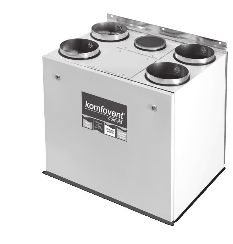
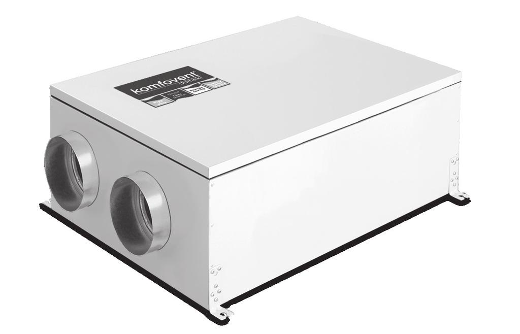
DOMEKT. Residential ventilation air handling units
 Residential ventilation air handling units DOMEKT Efficient heat recovery till 92% Low energy consumption Silent operation Integrated automatic control Healthy indoor climate and energy saving We spend
Heat Recovery Air Handling Units
 Heat Recovery ir Handling Units OMEKT Heat recovery air handling Units OMEKT 1 KOMFOVENT OMEKT ir Handling Units Komfovent ir Handling units are made to create healthy indoor climate and ensure efficient
DOMEKT ReGO 400VE(W)-B Series Air Handling Units Installation and Maintenance Service Manual
-B Series Air Handling Units Installation and Maintenance Service Manual") DOMEKT ReGO 400VE(W)-B Series Air Handling Units EN Content Safety Requirements...3 Transportation...3 Brief Description of the Unit...5 Installation...6 Maintenance...11 Technical Information......13
DOMEKT ReGO 400VE(W)-B Series Air Handling Units EN Content Safety Requirements...3 Transportation...3 Brief Description of the Unit...5 Installation...6 Maintenance...11 Technical Information......13
- Data Brochure tekmarnet 4 Thermostat 542e
 - Data Brochure tekmarnet 4 Thermostat 542e D 542e 03/08 1 Information Brochure Choose controls to match application 2 Application Brochure Design your mechanical applications 3 Rough In Wiring Rough-in
VERSO Air Handling Units
 Energy efficient solutions for profitable indoor climate VERSO-S air supply units VERSO-R air handling units equipped with regeneration system VERSO-P air handling units equipped with recuperation system
Rectifier RC-series. Manual RC-series English MA doc. Manual Wall and 19 English
 Rectifier RC-series Manual RC-series English Manual Wall and 19 English Presentation The RC-series is a rectifier for either directly powering the load or for use together with batteries. It is designed
C5.1. EN Electrical installation and Operation Manual
 C5.1 EN Electrical installation and Operation Manual Content 1. ELECTRICAL INSTALLATION MANUAL... 4 1.1. Air Handling Units Sections Connection... 4 1.2. Electric Power Supply Connection... 4 1.3. External
VERSO DOMEKT. Residential ventilation units m³/h. Non residential ventilation units m³/h
 VENTILATION equipment VENTILATION equipment content DOMEKT Residential ventilation units 50 1 000 m³/h 15 VERSO Non residential ventilation units 1000 34 000 m³/h 61 Domekt R 17 Domekt R 200 V 19 Domekt
- Brochure D 542. Introduction. Features. tekmarnet 4 Thermostat /05. 5 Data Brochure Control settings wiring instructions
 - Brochure tekmarnet 4 Thermostat 542 D 542 06/05 1 Information Brochure Choose controls to match application Application Brochure Design your mechanical applications 2 3 Rough In Wiring Rough-in 4 Wiring
SAT-3 Room Temperature Controller
 SAT-3 Room Temperature Controller USER S OPERATING INSTRUCTIONS Contents Introduction 5 Features Summary 5 Operation 7 On/Off 7 Room Temperature Adjustment 7 Operating Mode Selection 8 Fan Speed Selection
BLAUAIR AUTOMATIC CONTROL SYSTEM
 BLAUAIR AUTOMATIC CONTROL SYSTEM S30 (KVENT, TH-TUNE) S31 (KVENT) S32 (KVENT, PGDE) EN USER S MANUAL CONTENTS Safety requirements... 3 Purpose... 4 Technical data... 5 Installation and set-up... 6 Control...
Rooftop Thermostat Controller Specification and Installation Instructions. Model TRT2422
 ºF / º C Rooftop Thermostat Controller Model TRT2422 Description The TRT2422 is a combination controller and thermostat with a built-in scheduler, which is designed for simple and accurate control of single
4 Wiring Brochure Wiring and
 - Brochure tekmarnet 4 Thermostat 544 D 544 06/05 1 Information Brochure Choose controls to match application Application Brochure Design your mechanical applications 2 3 Rough In Wiring Rough-in 4 Wiring
Control solutions Biofloor
 TEF234 Electronic room thermostat with display 230V & 24V COMAP proposes a new control system for heating and cooling underfloor. Consisting of a 6 or 10- channels controller (MCF234), analogic (TAF234)
Safety & Installation Instructions
 Model 8800 Universal Communicating Thermostat Safety & Installation Instructions READ AND SAVE THESE INSTRUCTIONS Table of contents Installation Installation location recommendations... 2 Thermostat mounting...
Air handling units KLASIK. Unique solutions available Flexible performance & economy Reliable, stable & efficient Tight casing & perfect insulation
 Air handling units KLASIK Unique solutions available Flexible performance & economy Reliable, stable & efficient Tight casing & perfect insulation KLASIK air handling units Customer oriented and unique
Dryer Controller M720
 User Manual Dryer Controller M720 Hardware version 2.00 Software version 2.00 Manual M720 Dryer controller Page 1 of 60 Document history Preliminary version: - Created in April, 2009 Hardware Version 2.00,
USER'S MANUAL PU SENS 01 (A11) PU SENS 01 (A19) Sensor Control Panel
 PU SENS 01 (A19) Sensor Control Panel") USER'S MANUAL PU SENS 01 (A11) PU SENS 01 (A19) Sensor Control Panel PU SENS 01 CONTENTS Safety requirements... 3 Purpose... 4 Technical data... 4 Overall dimensions [mm]... 4 Mounting and set-up... 5
USER'S MANUAL PU SENS 01 (A11) PU SENS 01 (A19) Sensor Control Panel PU SENS 01 CONTENTS Safety requirements... 3 Purpose... 4 Technical data... 4 Overall dimensions [mm]... 4 Mounting and set-up... 5
For the owner and the heating engineer. Operating and Installation Manual VRC 400. Programmable weather compensator with separat HW time control
 For the owner and the heating engineer Operating and Installation Manual VRC 400 Programmable weather compensator with separat HW time control GB Contents Contents Notes on the documentation..... 4 Symbols
AIR HANDLING UNIT WITH HEAT RECOVERY
 AIR HANDLING UNIT WITH HEAT RECOVERY Freshbox 100 EN OPERATION MANUAL Freshbox 100 www.blaubergventilatoren.de CONTENTS Safety requirements... 2 Purpose... 4 Delivery set... 4 Designation key... 4 Technical
Floor sensor (NTC) Temp (C o ) Value (kohm) 10 o C 19,9 kohm 15 o C 15,7 kohm 20 o C 12,5 kohm 25 o C 10,0 kohm 30 o C 8,0 kohm
 Temp (C o ) Value (kohm) 10 o C 19,9 kohm 15 o C 15,7 kohm 20 o C 12,5 kohm 25 o C 10,0 kohm 30 o C 8,0 kohm") FENIX THERM 350 a) b) Fig 1 c) L N Load Load SG - Not in use Sensor Sensor Fig 2 Fig 3 Fig 4 1 9 8 [ 6 [ 7 5 Fig 5 2 4 3 Floor sensor (NTC) Temp (C o ) Value (kohm) 10 o C 19,9 kohm 15 o C 15,7 kohm 20
FENIX THERM 350 a) b) Fig 1 c) L N Load Load SG - Not in use Sensor Sensor Fig 2 Fig 3 Fig 4 1 9 8 [ 6 [ 7 5 Fig 5 2 4 3 Floor sensor (NTC) Temp (C o ) Value (kohm) 10 o C 19,9 kohm 15 o C 15,7 kohm 20
REMOTE CONTROL FOR CHILLER MYCHILLER
 REMOTE CONTROL FOR CHILLER MYCHILLER GENERAL FEATURES... 3 MAIN FUNCTIONS AND EQUIPMENT:... 3 LCD DISPLAY... 4 KEYBOARD... 5 BOARD CONFIGURATION... 7 LIST OF MAIN PARAMETERS... 7 CONFIGURATION OF MAIN
Silencer Preheater unit Electric post-heating unit Water circulated post-heating unit CO 2 sensor %RH sensor Pressure difference switch LON converter
 VALLOX Product Code: 3158400 L 3158410 R SILENCER (OPTIONAL) INSTRUCTIONS FOR USE AND MAINTENANCE WATER CIRCULATED POST-HEATING UNIT (OPTIONAL) ELECTRIC POST-HEATING UNIT (OPTIONAL)) PREHEATER (OPTIONAL)
User Manual. Dryer Controller M720
 User Manual Dryer Controller M720 Hardware version 1.00 Software version 1.00 Preliminary version Manual M720 Dryer controller Page 1 of 42 Document history Preliminary version: - Created in April, 2009
Product Manual SZ1009
 Product Manual SZ1009 Conventional Heating & Cooling Thermostats with Heat Pump Mode Communicating Thermostats Description The SZ1009 is a microprocessor-based mable thermostats designed for conventional
User Guide. Color Touchscreen Programmable Residential Thermostat. ComfortSense Model: 13H /2015 Supersedes 7/2015
 User Guide Color Touchscreen Programmable Residential Thermostat ComfortSense 7500 Model: 13H14 507503-01 10/2015 Supersedes 7/2015 TABLE OF CONTENTS Features... 2 Temperature Dial Indicator... 3 Home
USER MANUAL S203. Controller for three circuits. - control for 2 heating circuits - 1 domestic hot water control. Saving energy, creating comfort
 USER MANUAL S203 Controller for three circuits - control for 2 heating circuits - 1 domestic hot water control Saving energy, creating comfort This user manual consists of two parts. Issues that are intended
DOMEKT ReCU 400VE(W)CF-EC-C4 Series Air Handling Units Installation and Maintenance Service Manual
CF-EC-C4 Series Air Handling Units Installation and Maintenance Service Manual") DOMEKT ReCU 400VE(W)CF-EC-C4 Series Air Handling Units Installation and Maintenance Service Manual EN Content Safety Requirements...3 Transportation...3 Brief Description of the Unit...5 Installation...6
DOMEKT ReCU 400VE(W)CF-EC-C4 Series Air Handling Units Installation and Maintenance Service Manual EN Content Safety Requirements...3 Transportation...3 Brief Description of the Unit...5 Installation...6
Parts Diagram. Up button. Down button. Right (fan) button. Left (system) button. RC/RH Jumper. Field programming pins
 button. Left (system) button. RC/RH Jumper. Field programming pins") Table of Contents Parts Diagram........................................................... 1 Icon Descriptions......................................................... 2 Specifications...........................................................
Table of Contents Parts Diagram........................................................... 1 Icon Descriptions......................................................... 2 Specifications...........................................................
C6.1 C6.2. EN Electrical installation and Operation Manual
 C6.1 C6.2 EN Electrical installation and Operation Manual EN Content 1. ELECTRICAL INSTALLATION INSTRUCTIONS... 3 1.1. Power supply connection... 3 1.2. Control panel installation... 3 1.3. Connection
USER MANUAL WARNING! CONTENTS MODEL 1 SPECIFICATIONS READ ALL INSTRUCTIONS BEFORE PROCEEDING 2 INSTALLATION
 MODEL 5100 USER MANUAL Compatible with low voltage multi-stage heat/cool systems with up to two stages of heating and two stages of cooling. READ ALL INSTRUCTIONS BEFORE PROCEEDING 1 2 3 4 5 6 7 CONTENTS
SC Installation, Operation & Application Guide
 SC 5211 2-Stage Heat Pump Auto Changeover Hardwire Programmable Electronic Thermostat 7-Day, 5-2-Day or 5-1-1-Day Programmable Configurable 2-Stage Heat Pump Systems Large Display With Backlight Selectable
Eswa DC-1. Thermostat for Floor Heating
 Eswa DC-1 Thermostat for Floor Heating The Eswa DC-1 is a thermostat which can be used for 7-day programming of floor heating systems or for limiting floor temperatures. This thermostat conforms to the
Series VUT PW EC. wool internal heat and sound-insulating layer for VUT PE/PW 350, 600, 1000 units and 50 mm for VUT PE/PW 200, 3000 units.
 AIR HANDLING UNITS WITH HEAT RECOVERY Series VUT PE EC Series SAS908 control panel SAS908 control panel Ceiling mounted energy saving Air Handling Units (AHU) with the air capacity up to 4000 m 3 /h and
DOMEKT. Heat Recovery Air Handling Units
 Heat Recovery ir Handling Units OMKT Heat Recovery ir Handling Units OMKT KOMFOVNT OMKT air handling units Komfovent air handling units are made to create healthy indoor climate and ensure efficient energy
Instruction FH-CWP Thermostat
 Instruction FH-CWP Thermostat Index Instruction FH-CWP Thermostat 1. Functional Overview.......................... 3 2. Mounting..................................... 4 3. Installation....................................
Lubrication cycle IP Enclosure Rating. 110 VAC, 220/230 VAC (50/60 Hz) Alarm Fault Relay Contacts. IP-55 (Liquid tight connector)
 Alarm Fault Relay Contacts. IP-55 (Liquid tight connector)") SMAC Controller Industrial Lubrication Systems Operation The SMAC Controller is a multi-purpose programmable controller used with industrial lubrication systems. Controller settings are saved whenever
SMAC Controller Industrial Lubrication Systems Operation The SMAC Controller is a multi-purpose programmable controller used with industrial lubrication systems. Controller settings are saved whenever
AIR HEATING UNIT HEATMASTER ACJB INSTALLATION, OPERATION, MAINTENANCE AND SPARE PARTS
 AIR HEATING UNIT HEATMASTER ACJB INSTALLATION, OPERATION, MAINTENANCE AND SPARE PARTS 2 Air Heating unit ACJB - Technical manual CONTENTS OPERATION AND MAINTENANCE (FOR USER) System, functions, main components...3
INSTRUCTION MANUAL REMOTE CONTROL DEVICE EASYREMOTE
 INSTRUCTION MANUAL REMOTE CONTROL DEVICE EASYREMOTE Technical features Guide to LCD symbols Guide to keys Technical features Supply by communication bus Number of temperature levels 2 (DAY / NIGHT) Temperature
Air handling units KLASIK. Unique solutions available Flexible performance & economy Reliable, stable & efficient Tight casing & perfect insulation
 Air handling units KLASIK Unique solutions available Flexible performance & economy Reliable, stable & efficient Tight casing & perfect insulation KLASIK air handling units Customer oriented and unique
EXPERT TRI-STAR. Temperature controller. User s Manual
 Temperature controller r s Manual WARNINGS The warranty can be void if this product is used in a manner not specified by the manufacturer. Every effort has been made to ensure that this manual is complete,
DC 60 & DM 60 displays
 USER MANUAL DC 60 & DM 60 displays BALTIC FLEXAIR ENERGY AIRCOOLAIR COMPACTAIR FLATAIR (& Inverter) AQUALEAN DC60-DM60-IOM-1310-E www.lennoxemea.com Summaries 1 Display DC60 1.1 Introduction... 2 1.2
Description... 2 Construction... 2 Size and weight... 3 Installation and placement... 4
 These technical conditions will specify produced sizes and solution of the "Ventilating VBM-V box". This applies to production, design, ordering, supplies, assembly, operation and maintenance. Description...
REPAIR INSTRUCTIONS. TUMBLE DRYER Vented WTA34.. / WTA35..
 REPAIR INSTRUCTIONS TUMLE DRYER Vented WTA34.. / WTA35.. I. SAFETY INFORMATION Page 1 II. OPERATION Page 1 III. DESCRIPTION OF FUNCTION / TECHNICAL INFORMATION Page 2 IV. CONSUMPTION RATES / ENERGY REQUIREMENT
USER MANUAL MODEL READ ALL INSTRUCTIONS BEFORE PROCEEDING. 5-2 Day Programmable Multi-Stage 2 Heat/1 Cool Heat Pump Digital Thermostat
 WARNING! Important Safety Information Builder MODEL 2200 Series 5-2 Day Programmable Multi-Stage 2 Heat/1 Cool Heat Pump Digital Thermostat USER MANUAL Compatible with low voltage multi stage heat/cool
Instruction manual. Aluminium radiator with ceramic heart. Smart Electric Heaters
 Instruction manual Aluminium radiator with ceramic heart Smart Electric Heaters READ THIS CAREFULLY BEFORE USING THIS DEVICE FOR THE FIRST TIME. PAY ATTENTION: to avoid overheating, do not cover the appliance.
Installation and Operating Manual
 Installation and Operating Manual SR868C6 System Regulator for Solar Thermal Systems Display Panel Illustration Pos. Button on display panel Button description 1 Green lamp Power indication lamp 2 On/Off
USER'S OPERATING INSTRUCTIONS
 SAT-2 Thermostat COOL FAN DRY HEAT AUTO SLEEP SWING AUTO ZONE SUN MON TUE WED THU FRI SAT HEATER ON OFF ERR UNIT USER'S OPERATING INSTRUCTIONS CONTENTS Page Introduction 3 Features Summary 3 Display 4
TH146-P-2H1C. 1. Introduction. 2. Installation. 1.1 Applications. 2.1 Control Module (CT280-2H1C) 1.2 Supplied Parts. 1.
 1.2 Supplied Parts. 1.") TH146-P-2H1C Installation Guide Programmable 2H1C Controller Removable Connector * Removable Connector * TH146-P User Console CT280-2H1C Control Module AC144-03 Outdoor Temperature Sensor * To remove a
TH146-P-2H1C Installation Guide Programmable 2H1C Controller Removable Connector * Removable Connector * TH146-P User Console CT280-2H1C Control Module AC144-03 Outdoor Temperature Sensor * To remove a
Digital Programmable
 www.geappliances.com Digital Programmable Thermostats Operating Instructions Auto Changeover..........10 Day/Time Setting Mode.....6 Default Mode...............4 Fan Control...............10 Hold and Temporary
Product Manual SZ1022/SZ1031/SZ1035/
 Product Manual SZ1022/SZ1031/SZ1035/ Conventional Heating & Cooling Thermostats Communicating Thermostats Description The SZ1022, SZ1031, and SZ1035, are microprocessorbased mable thermostats designed
SmartVent. Digital Controller User Guide Manual. NZ s Home Ventilation Specialists
 SmartVent NZ s Home Ventilation Specialists Digital Controller User Guide Manual www.smartvent.co.nz Introducing... SmartVent Digital Control Panel 12x2 LCD Display with Backlight On/Off Button Button
ETN-24-HC21-PROG Econo-Vent
 ETN-24-HC21-PROG Econo-Vent Owner's Manual - Installation and Operating Instructions Cat. G030121 Rev. 3.1 02.06 Meitav-tec Ltd (Contel group) Tel: 972-3-9626462 ax: 972-3-9626620 www.meitavtec.com - support@meitavtec.com
User s guide. Multiple programming Electronic thermostat
 SYSTÈME QUALITÉ CERTIFIÉ - REGISTERED QUALITY SYSTEM User s guide STE402P+ Multiple programming Electronic thermostat Energy Verified For further information or to consult this guide online, please visit
USER MANUAL WARNING! CONTENTS MODEL 1 SPECIFICATIONS READ ALL INSTRUCTIONS BEFORE PROCEEDING 2 INSTALLATION. Premier Series
 Premier Series MODEL 5000 USER MANUAL 5-2 Day Programmable Single Stage Heat/Cool Digital Thermostat Compatible with low voltage single stage gas, oil or electric heating or cooling systems, including
HEALTHY HOME SYSTEM CONTROL Plus Model: HHSC+
 HEALTHY HOME SYSTEM CONTROL Plus Model: HHSC+ The Field Controls Healthy Home System Controller Plus (HHSC+) is designed to work in conjunction with the forced air HVAC system to periodically introduce
SAVE VTR 250/B. User Manual. Document in original language A001
 SAVE VTR 250/B User Manual Document in original language 211474 A001 GB Copyright Systemair UAB All rights reserved E&OE Systemair UAB reserves the rights to change their products without notice. This
Instructions for the heat exchanger control system SILVER C RX, RECOnomic, sizes 100/120, RECOsorptic, sizes
 Instructions for the heat exchanger control system SILVER C RX, RECOnomic, sizes 100/120, RECOsorptic, sizes 50-120 1 General The heat exchanger control system is a control system for 380 W step motors
Room thermostat with Auto Timer, Option External Input
 s 1 422 Room thermostat with Auto imer, Option External Input for heating systems RDE100.. Room temperature control 2-position control with On/Off output for heating Comfort, Economy, Auto timer and Protection
HEAT RECOVERY VENTILATOR FAIR-80 EC INSTALLATION AND USER MANUAL
 HEAT RECOVERY VENTILATOR FAIR-80 EC INSTALLATION AND USER MANUAL QUALITY CONTROLLED THE QUALITY GOALS OF AIR CONDITIONING COME TRUE RECOVERY SYSTEM WITH THE Air ventilation system TALTERI is designed to
SINGLE ROOM HEAT RECOVERY AIR HANDLING UNIT
 SINGLE ROOM HEAT RECOVERY AIR HANDLING UNIT EN OPERATION MANUAL www.blaubergventilatoren.de CONTENTS 3 Introduction 3 General 3 Safety rules 3 Transportation and storage rules 3 Manufacturer's warranty
ggg Air Handling Unit RT 700/1000S-EC-RS INSTALLATION OPERATION & CONTROL PANEL MAINTENANCE & SERVICE
 ggg INSTALLATION DESIGN & TECHNICAL INFORMATION OPERATION & CONTROL PANEL MAINTENANCE & SERVICE Exhaust air filter, article No: Q4871 Supply air filter, article No: Q4872 June 2013 1 CONTENTS Page Installation
ComfortSense 7500 Commercial Thermostat. User Guide
 ComfortSense 7500 Commercial Thermostat User Guide 507505-02 6/2018 Supersedes 5/2017 Table of Contents Features...2 Home Screen Temperature Indicator...2 Home Screen Information...3 Operating Mode Selection...5
SAS908WHB-3-RF/B WIRELESS THERMOSTAT
 SAS908WHB-3-RF/B WIRELESS THERMOSTAT Installation and operation instructions 908WHB-3-RF/B can replace most common residential thermostat and is designed to be used with electric, gas or oil heating control
Sensor Control Panel
 USER S MANUAL PU SENS 01 Sensor Control Panel V55-6EN-03(SENS).indd 1 18.08.2015 10:37:16 2 PU SENS 01 CONTENTS Safety Requirements 2 Main Technical Data 3 Control Panel Mounting 3 Control Panel Operation
Infinity Control. Homeowner s Guide. The New Feeling of Comfort
 TM Infinity Control Homeowner s Guide The New Feeling of Comfort CONGRATULATIONS! Your decision to choose the Carrier Infinity Control puts you in a select group of homeowners who understand the value
Clima Infrared Radiant & Convection Panel
 Clima Infrared Radiant & Convection Panel Model S2030/1 Operating and Instruction Manual Please retain these instructions in a safe place for future reference. Ed. 05112015 cjw 1 References: n 1 min. 50cm
OWNERS MANUAL YEAR LIMITED WARRANTY READ ALL INSTRUCTIONS BEFORE PROCEEDING. Store this booklet for future reference
 5100 Premier Series 7-Day Programmable 2-Heat / 2-Cool Heat /Cool Digital Thermostat OWNERS MANUAL Compatible with low voltage multi-stage heat / cool systems with up to two stages of heating and two stages
Evolution Control. Zone Control Homeowner s Guide
 Evolution Control Zone Control Homeowner s Guide CONGRATULATIONS! Your decision to choose the Bryant Evolution Control puts you in a select group of homeowners who understand the value of precise comfort
Programmable Heat-Pump Thermostat TAYSTAT 540
 Programmable Heat-Pump Thermostat TAYSTAT 540 OWNER S GUIDE FEATURES The Trane Co. sells comfort systems. Comfort is achieved through matching the correct equipment and controls. This thermostat is designed
Operating instructions
 Operating instructions Control unit - CGL Zone 0.0 C Friday 3/0/08 : 6 Wolf GmbH Postfach 380 D-84048 Mainburg Tel. +49 (0)875/74-0 Fax +49 (0)875/74600 Internet: www.wolf-heiztechnik.de Document no.:
Smart Temp. Model
 Smart Temp Model 42-160 SINGLE STAGE PROGRAMMABLE THERMOSTAT 1 Heat / 1 Cool Single Stage Thermostat. 5+2 Programmable, Compatible with Gas Heat & Heat Pump System Installation and Operation Manual SPECIFICATIONS:--------------------------------------------------------------------------------
Operator: Save these instructions for future use!
 WHITE-RODGERS 1F82-51 Programmable Electronic Digital Heat Pump Thermostat INSTALLATION AND OPERATION INSTRUCTIONS Operator: Save these instructions for future use! FAILURE TO READ AND FOLLOW ALL INSTRUCTIONS
Operating your heating system with the Prefect PRE5701 Programable Thermostat
 Operating your heating system with the Prefect PRE5701 Programable Thermostat 1 Your central heating system has been designed to provide a comfortable and flexible living environment, enabling you to have
Energy efficient ventilation equipment
 Energy efficient ventilation equipment Komfovent Energy Efficient KOMFOVENT is a trademark for ventilation products produced by the company AMALVA. KOMFOVENT stands for comfort, healthy indoor climate,
CONTROL PANEL INTERFACE ACTIVATE THE GENERATOR DISPLAY INTERFACE MENUS. Control Panel USING THE AUTO/OFF/MANUAL SWITCH
 CONTROL PANEL INTERFACE USING THE AUTO/OFF/MANUAL SWITCH With the switch set to AUTO, the engine may crank and start at any time without warning. Such automatic starting occurs when utility power source
VAV Thermostat Controller Specification and Installation Instructions. Model TRO24T4XYZ1
 Model TRO24T4XYZ1 Description The TRO24T4XYZ1 is a combination controller and thermostat. The VAV Thermostat Controller is designed for simple and accurate control of any variable air volume box in a number
INSTALLATION OPERATION & MAINTENANCE INSTRUCTION HEAT RECOVERY UNITS VHR MODELS
 INSTALLATION OPERATION & MAINTENANCE INSTRUCTION HEAT RECOVERY UNITS VHR MODELS TSEK VENCO Havalandırma ve Makina San.ve Tic. A.Ş. 2004. Cad. No:5 45400 OSB Turgutlu MANISA / TURKİYE Tel: +90 (236) 332
Feed Whiz INSTRUCTION MANUAL
 Feed Whiz INSTRUCTION MANUAL IMPORTANT READ THIS BEFORE USING THE FEED WHIZ AUTOMATIC FEEDER Contents 1. Introduction... 2 1.1. Feed Whiz Introduction to the Horse or Animal... 2 1.2. Disclaimer... 2 1.3.
aura-t TP536/EU ventilation systems
 EN aura-t TP536/EU Product Manual HRV controller ventilation systems Warnings, Safety information and Guidance Important Information Read instructions fully before the installing this appliance. 1. This
USER'S MANUAL. Micra 150 HEAT RECOVERY UNIT
 USER'S MANUAL Micra 150 HEAT RECOVERY UNIT 2 Micra 150 CONTENTS Introduction Use Included in the Box Designation Key Example Technical data Safety requirements DESIGN AND OPERATION Mounting and Installation
Room thermostat with Auto Timer, Option External Input
 s 1 422 Room thermostat with Auto imer, Option External Input for heating systems RDE100.. Room temperature control 2-position control with On/Off output for heating Comfort, Economy, Auto timer and Protection
GreenCon On/Off Room Thermostat
 Description Features: Scandinavian design with white backlight; User-friendly interactive interface; Room temperature display and settings; 12 or 24 hour clock display and settings; Three-speed manual/automatic
AIR HANDLING UNITS RIS P EKO 3.0. New range - 5 sizes, 20 models! Efficient EC. E f f i c i e n c y up to 94%! E x t r e m e l y low height! fans!
 AIR HANDLING UNITS RIS P EKO 3.0 1 2 3 4 fans! Efficient EC E f f i c i e n c y up to 94%! E x t r e m e l y low height! New range - 5 sizes, 20 models! Contents Basic features 4 RIS P EKO 3.0 full range
Intelligent Security & Fire Ltd
 full installation, commissioning and operating manuals can be downloaded from www.haes-systems.co.uk combined addressable / conventional fire alarm control panel User Guide Approved Document No. MFBU-04
GreenCon On/Off Room Thermostat
 Description Features: Scandinavian design with white backlight; User-friendly interactive interface; Room temperature display and settings; 12 or 24 hour clock display and settings; Three-speed manual/automatic
SmartVent. Keypad Controller User Guide Manual. NZ s Home Ventilation Specialists
 SmartVent NZ s Home Ventilation Specialists Keypad Controller User Guide Manual www.smartvent.co.nz Introducing... SmartVent Keypad Control Panel 12x2 LCD Display with Backlight On/Off Button Mode Button
HEAT PUMP PROGRAMMABLE THERMOSTAT
 HEAT PUMP PROGRAMMABLE THERMOSTAT SA PM 3 COOL TEMP Form 44014-01 r010408 Model 43168 Owners Manual 1 Congratulations! Heat Pump Programmable Thermostat Model 43168 THERMOSTAT CONTROLS Switches & Buttons...15
ENG. IDEO 325 Ecowatt. Installation Manual
 ENG IDEO 325 Ecowatt Installation Manual Before manipulating this device, disconnect the electricity supply. During normal operation, never stop the ventilation system. General Information High-performance
USER MANUAL. Air handling unit with heat recovery. VUT 300 EVK mini EC VUT 300 EV mini EC VUT 301 EVK mini EC VUT 301 EV mini EC
 USER MANUAL Air handling unit with heat recovery VUT 300 EVK mini EC VUT 300 EV mini EC VUT 301 EVK mini EC VUT 301 EV mini EC 2 CONTENTS Introduction Use Delivery set Structural designation key Technical
Series. Suspended air supply units with the air capacity up to 4100 m 3 /h in the sound- and heat-insulated casing with the water heater
 SUPPLY UNITS Series VENTS PA E Series VENTS PA W A13 control panel A13 control panel Suspended air supply units with the air capacity up to 3350 m 3 /h in the sound- and heat-insulated casing with the
MENU. Steamist Xenio Sauna Control, Product: 0941 and 0942 Model: S170-1 and S Steamist Xenio Sauna Control. Contents
 ETL LISTED CONFORMS TO UL STD 875 CERTIFIED TO CAN/CSA STD E60335-2-53-05 Steamist Xenio Sauna Control, Product: 094 and 0942 Model: S70- and S70-3 These instructions for installation and use are intended
Operator: Save these instructions for future use!
 WHITE-RODGERS 1F81-51 Programmable Electronic Digital Multi-stage Thermostat INSTALLATION AND OPERATION INSTRUCTIONS Operator: Save these instructions for future use! FAILURE TO READ AND FOLLOW ALL INSTRUCTIONS
1. COMMISSIONING OF THE BOILER en DESCRIPTION FUNCTION BUTTON DESCRIPTION SYMBOL DISPLAY
 RC 06 0712_1403 it - Istruzioni TELECONTROLLO en - Remote controller instruction hu - Utasítás TÁVVEZÉRLÉS ru - Руководство по эксплуатации pl - Instrukcja obsługi { 1. Commissioning of the boiler 26 2.
User Manual HEAT RECOVERY VENTILATORS 1000 HE HE HE HE HE HE COMPACT 5585 COMPACT READ AND SAVE THESE INSTRUCTIONS.
 User Manual HEAT RECOVERY VENTILATORS MODELS: 1000 HE HE 1.3 2000 HE HE 1.8 3000 HE HE 2.6 3055 COMPACT 5585 COMPACT VB0021 READ AND SAVE THESE INSTRUCTIONS. VVI, 550 Lemire Blvd., Drummondville, QC, Canada
User s Manual
 997-060180-4e User s Manual 8403-060 Menu Driven Display 1120-445 I. CONTROLLER OPERATION ADJUSTING TEMPERATURE (Temporary Override when in Programmable mode) 1. Before you can adjust the temperature,