Paco RCH. G20/G25/G25.3 Natural gas. Installation manual (UK/IE) English. Store this document in a safe place DRU EN-US
|
|
|
- Rodney Lee
- 5 years ago
- Views:
Transcription
 Store this document in a")
1 Paco RH G20/G25/G25.3 Natural gas Installation manual (/IE) Store this document in a safe place DRU EN-US
2 ontents 1. Introduction 2. E declaration 3. SFETY 3.1 General 3.2 Regulations 3.3 Precautions / safety instructions at installation 3.4 Principle of ignition cycle 4. Removing the packaging 5. Installation 5.1 Type of gas Reconstruction to different type of gas 5.2 Gas connection 5.3 Electric connection 5.4 Placing the appliance 5.5 Placing a built-in appliance 5.6 Placing the chimney breast 5.7 Placing the control hatch 5.8 Flue gas discharge system appliances open combustion 5.9 Flue gas discharge / combustion air supply system appliances closed combustion 5.10 dditional instructions Placing the appliance How to position the fite in the chimney breast Mantel iron ontrol hatch 5.11 Glass panes Removing the glass pane Fitting the glass pane Mounting the front panel 5.12 djustment of the appliance djusting the baffle and the baffle plate 5.13 Positioning the logs 6. ontrol 6.1 Remote controls 6.2 lternative controls 7. Final inspection 7.1 Gastightness 7.2 Gas pressure/line-pressure 7.3 Ignition main burner 7.4 Flame picture 8. Maintenance 8.1 Parts 9. Delivery 10. Malfunctions ppendix 1 Malfunctions ppendix 2 Tables ppendix 3 Figures
3 1. Introduction DRU, a manufacturer of gas-fired heating appliances, develops and produces products that comply with the highest possible quality, performance and safety requirements. This appliance has a E label, which means that it complies with the essential requirements of the European Gas ppliance Directive. The appliance is supplied with an installation manual and a user manual. The appliance may only be installed by recognised installers who are skilled in the field of gas heating and electricity. The information in this installation manual will ensure the appliance is installed in such a way that it will function properly and safely. This manual discusses the installation of the appliance and the regulations that apply to the installation. In addition, the appliance's technical data are shown and information is provided about maintenance, possible malfunctions that might occur and their possible causes. The figures are at the back of this installation manual, in the appendix. Fully and carefully read and use this installation manual, before installing the appliance. When using the DRU Powervent system or DRU M system, the accompanying installation manual should also be read completely and carefully, before installation work is started. The following symbols are used in the manuals to indicate important information: Work to be performed!tip Suggestions and recommendations You will need these instructions to prevent problems that might occur during installation and/or use. You need these instructions to prevent fire, personal injury or other serious damages. fter final delivery, the manuals should be handed over to the user. 2. E declaration We hereby declare that the design and construction of DRU's gas-fired heating appliance comply with the essential requirements of the Gas ppliance Directive. Product: Type: EE directives: Standards: gas-fired heating appliance Paco RH 2009/142/E; 2006/95/E; 2004/108/E NEN-EN-613; NEN-EN-613/1; EN Internal precautions at the company will guarantee that appliances produced in series comply with the essential requirements of the E directives in force and the standards derived from them. This declaration will lose its validity if adjustments are made to the appliance without prior written permission by DRU. copy of the test certificate can be downloaded via M.J.M. Gelten General manager Postbus 1021, 6920 Duiven Ratio 8, 6921 RW Duiven
4 3. SFETY 3.1 General Observe the generally applicable regulations and precautions/safety instructions in this manual. First check in appendix 2, table 2 whether the appliance to be installed has the correct technical version. Read the manual carefully to ensure a proper and safe installation of the appliance. Observe the regulations/instructions in this manual. 3.2 Regulations Please install the appliance in accordance with the applicable national, local and constructional (installation) regulations. 3.3 Precautions / safety instructions at installation arefully observe the following precautions/safety regulations: The appliance may only be installed and maintained by recognised installers who are skilled in the field of gas heating and electricity. Do not make any changes to the appliance. When installing a built-in appliance: Use non combustible and heat-resistant materials for the chimney breast, including the top of the chimney breast, the material in the chimney breast and the back wall against which the appliance will be placed. For this you can use both sheet material and stone-like materials. Take sufficient measures to prevent temperature of a wall behind the chimney breast becoming too high, including the materials and/or objects behind the wall. omply with the minimum required internal sizes of the chimney breast. Vent the chimney breast by means of ventilation holes with a combined passage as stated further down in the text. Use heat-resistant electrical wiring. Place heat-resistant electrical wiring away from the appliance and as low as possible in the chimney breast. This has to do with the temperature development in the chimney breast. Only use the flue gas discharge / combustion air supply system supplied by DRU. When installing a free-standing appliance: place the appliance away from the back wall by the minimum distance stated further down in the text. Do not cover the appliance and/or do not wrap it in an insulation blanket or any other material. Keep combustible objects and/or materials outside the appliance's radiation range. This radiation range is 500 mm, unless stated otherwise. Only use the accompanying set, such as the wood or pebble set, and place it exactly as described. Leave space around the ionisation pin and spark electrode and never place glow material around these pins. Make sure there is no dirt in gas pipes and connections. Place a gas tap in accordance with applicable regulations. Prior to putting into operation, check the complete installation for gastightness. Prevent blocking of the explosion hatch(es) at the top and/or bottom of the appliance and check whether it/they connect(s) properly to the sealing surface before the appliance is built in. Do not ignite the appliance before the gas, discharge and electric connections have been fully installed, first observe the procedure described in chapter 7.3. Do not use the appliance when a pane is broken and/or cracked, until it has been replaced. In case of broken or torn glass panes, the appliance may not be used.
5 3.4 Principle of ignition cycle elow you will find a brief description of how this appliance is ignited. The receiver in the appliance will get a signal from the remote control to start the ignition process. The receiver will get the signal to start the ignition process. This signal is passed on to the burner device, after which, if applicable, the relay for the Powervent System is switched. fter an 8 second interval, the ignition on the spark electrodes will start. If no Powervent System is connected, only the relay will switch and the ignition will start immediately. The main burner will be ignited at about 50% of its capacity. This will prevent a larger amount of gas in the combustion chamber, if no ignition takes place. When the gas ignites, ionization will have to be detected. In order to make sure the flame has passed over, this will take place at the other side of the burner. When ionization is detected, the gas control will modulate to 100%. In case of an appliance with a switchable second burner, the second valve is switched (you will be able to hear a 'click') in order to ignite the second burner. fter ignition of the second burner, the appliance will always go to the full position (full capacity). This will guarantee that the second burner will actually ignite. The second burner can be switched on and off manually, by means of the remote control. In case of switching on manually, the appliance will first return to full load. The appliance's control unit is characterized by stringent safety requirements. It is possible that the burning appliance switches off automatically and then switches back on again. This is not a failure, but a check. The moment the appliance's control unit is connected to mains voltage, the control unit will perform this check every 24 hours. If the appliance is burning at that time, the appliance will extinguish and then start again immediately. If you wish to prevent this, you can remove the plug and insert it again at a time during the 24 hours when the appliance is never or hardly ever burning. 4. Removing the packaging Note the following items when removing the packaging: Remove all packaging materials. Remove all supplied components in, on and/or at the appliance. heck the appliance and accessories for damages (during transport). If necessary, contact your supplier. Never install if an appliance is damaged! Remove any screws that are used to fix the appliance to a platform or pallet. Glass is a ceramic material. Very small irregularities in the glass panes cannot be avoided, but are within the required quality standards. Keep plastic bags away from children. ppendix 2, table 1 indicates which components should be available after unpackaging. ontact the supplier if you find that not all components have been supplied. Packaging must be disposed of in accordance with the regulations.
6 5. Installation 5.1 Type of gas The data plate indicates for which type of gas, gas pressure and for which country this appliance is intended. The data plate can be found on the appliance or can be attached to a chain to which it should remain attached. heck whether the appliance is suitable for the type of gas and gas pressure used at the location Reconstruction to different type of gas In order to convert this appliance to a different type of gas, please contact DRU's service department and ask for the possibilities. 5.2 Gas connection Place a gas tap in the gas pipe in accordance with the applicable regulations. The gas connection on the gas control is located next to the receiver (see ppendix 3, fig. 38 (G)). Make sure there is no dirt in gas pipes and connections. The following requirements apply to the gas connection: Use a gas pipe with the correct dimensions, so that no pressure loss can occur. The gas tap must be approved (in the EU this will be the E mark). You should always be able to reach the gas tap. 5.3 Electric connection In case of a 230 Volt electrical connection, provide proper grounding. Place this electrical connection away from the appliance, as low as possible in the chimney breast. This has to do with the temperature development in the chimney breast. Protect the gas control and electric components, hereafter referred to as the gas control, against building dust and moisture! For connecting the receiver and control panel at an appliance equipped with the M system, you must observe the instructions in the supplied manual onnecting the switch contact (if applicable) It is possible to operate one or more lamps (in case of several lamps, a maximum of 8/250V/30VD) via the remote control of the appliance. You could think of the lamps of Dru's lux elements. For this, you can use switch contact on the receiver (see appendix 3, fig 36). The switch contact is not polar sensitive onnecting the Dru Omivent (if applicable) If the appliance is equipped with a Dru Lux Omnivent system, it can be operated with the remote control and connected (see appendix 3, fig 36, ()). The supply to this connection is equal to the mains voltage. 5.4 Placing the appliance Place the appliance in front of a heat-resistant and non combustible wall. The wall brackets on a built-in appliance ensure that the minimum distance to the wall is maintained. Ensure there are no combustible objects or materials present in the fire's radiation range, within a distance of 500 mm. Place the concentric system in such a way that no fire hazard is ever created (also see section 5.8). Take sufficient measures to prevent temperature of a wall behind the chimney breast becoming too high, including the materials and/or objects behind the wall. Do not cover the appliance and/or do not wrap it in an insulation blanket or any other material. Make sure that the appliance to be installed has a stable position. Fasten possible extending legs with the self-tapping screws.
7 When installing a built-in appliance, always take the following into account: The minimum construction measurements according to ppendix 3, Fig. 1 and 2. The construction height of the appliance. Provide a gas connection at the location. For details, see section 5.2. Make a passage for the concentric system; for details, see section dditional instructions for the appliance to be installed can be found from section Placing a built-in appliance (if applicable) Not all built in DRU appliances are supplied with a control hatch. uilt in appliances must be installed with the DRU control hatch. This is necessary to ensure a durable, safe and proper operation. The DRU control hatch can be ordered separately. Exceptions are: ppliances with supplied DRU guard cabinet. The DRU guard cabinet is intended for installation with a suspended platform. If the appliance will be connected to the DRU PowerVent system, the DRU control hatch has to be used after all. The gas control is mounted to the appliance. It must be taken out and placed in the control hatch at a later time. For placing the gas control in the control hatch, see section 5.7. Proceed as follows: Loosen the bracket with the gas control by loosening the self-tapping screws and screw the self-tapping screws back in the appliance. Place the bracket with gas control, together with the wiring of the ignition/ionisation cable(s), the flexible gas hose(s) and type plate with chain in the direction of the control hatch. The data plate should remain connected to the chain. Set the height of the appliance using the adjustable feet. Make the appliance level at the same time.!tip The construction frame can be adjusted afterwards for most 2- or 3 sided appliances. This allows a good contact of the construction frame with the chimney breast. djustment should take place before the appliance is built in. fter building in, adjustment is no longer possible. For 2- or 3-sided appliances that cannot be adjusted, we refer to section 5.9 'dditional instructions'. Do not ignite the appliance before the gas, discharge and electric connections have been fully installed, first observe the procedure described in chapter Placing the chimney breast (if applicable) For a good heat discharge and operation of the appliance, there should be sufficient space around the appliance. The chimney breast should be ventilated sufficiently by means of ventilation holes (incoming and outgoing). When an appliance is built in the floor, please take into account the minimum distances from a combustible floor. If applicable, additional information about this is provided from section 5.9 'dditional instructions'.
8 Use non combustible and heat-resistant materials for the chimney breast including the top of the chimney breast, the material in the chimney breast and the back wall of the chimney breast. The appliance is not a support structure. Make sure the appliance does not have to bear the weight of the chimney breast for example. The passage of the ventilation holes (outgoing), which are placed as high as possible, is stated in ppendix 2, Table 2. If no control hatch is placed in the chimney breast, an air supply of at least 80 cm 2 should be attached as low as possible. If there is, the control hatch will suffice as air supply. When placing the chimney breast, you should take the following into account (see ppendix 3, Fig. 2): The location for the control hatch: this must be placed as low as possible. The dimensions of the control hatch; see Placing the control hatch section 5.7. The location of the ventilation holes (V) (outgoing). Maintain a minimum 30 cm distance between the top of the ventilation hole (outgoing) and the ceiling of the house. The measurements of the glass pane, so that it can be placed/removed after placing the chimney breast. The protection of the gas control and the pipes against cement and plaster. If possible, you should place decorative strips, frames, etc., after any required structural work has been completed. Prevent the use of painter's tape. If this is not possible: use a good quality painter's tape and remove it immediately after plastering or painting work.!tip You should preferably apply the ventilation holes (outgoing) on both sides of the chimney breast. Use the DRU ventilation elements. heck the following issues, before the chimney breast is fully closed: Whether the discharge / concentric system is placed correctly. Whether the channels, fixing brackets and possible clip bindings, which cannot be reached after installation, are fastened by means of self-tapping screws. Do not plaster on or over the edges of the construction frame, because: The heat of the appliance could cause cracks. It will no longer be possible to remove/place the glass pane. When using stone-like materials and/or plaster finishing, allow the chimney breast to dry for at least six weeks prior to taking the appliance into operation in order to prevent cracks. 5.7 Placing the control hatch (if applicable) The control hatch (also see paragraphs 5.5 and 5.6) is placed as low as possible in the chimney breast. The bottom of the control hatch may not be placed higher in the appliance than the burner surface. Place control hatch and bracket with gas control indoors in a dry place only! number of components are placed in the control hatch, such as data plate, gas control and, if applicable, the components belonging to the DRU Powervent System. Place the control hatch as follows, see ppendix 3, Fig. 3 for details: Make an opening in the chimney breast, as described in the manual for the control hatch.!tip The opening in the chimney breast may be made horizontal and vertical. Place the inner frame (); unscrew bolts (D and F) for this. The inner frame should be placed in the correct way. Two positions are possible. Placing the inner frame with a rotation of 180 is not allowed (see ppendix 3, fig. 4).!Tip When the chimney breast is made of bricks, the inner frame can be built with bricks at the same time. In case of a different material, the inner frame can be glued or fastened with four countersunk screws. Remove the bracket with the gas control () from the appliance and place these self-tapping screws back in the appliance.
9 ttach the bracket with gas control to the inner frame (). Proceed as follows: Unwind the cables. This will, amongst other things, prevent a poor operation of the ignition. Unwind the flexible gas pipe(s). Mount the bracket with the gas control to the inner frame (). The slotted hole falls in allen screw (); the hole at the bottom falls over the head of allen screw (D). Fix the bracket with allen screw (). void kinks in the pipes. Do not lay the cables of the ionisation and ignition pins along metal parts, wiring and other components. onnect the gas pipe with gas tap (see section 5.2). leed the gas pipe.!tip If the gas tap is closed, the bracket with gas control can be easily removed by loosening the clamp coupling under the gas control and loosening the allen screw () by a few turns. The bracket with the gas control can now be lifted and removed towards the front out of the control hatch. onnect the 230 V mains voltage with earth connection. Various types of plug connections are supplied. The type of plug depends on the country where the appliance is placed. Place the data plate in its intended clamp (G). Mount the outer frame with door (E) to the inner frame using two allen screws (D and F).!Tip The outer frame can be placed in such a way that the door turns to the left or right. lways close the control hatch with the lock (H) because of the electricity behind the door (230V). You can operate the lock with a fitting flat object.
10 5.8 oncentric system General The appliance is connected to a flue gas discharge / combustion air supply system delivered by DRU, hereafter referred to as the concentric system. The diameter for this connection is indicated in appendix 2, table 2. The passage to the outside can be created with a wall terminal (11) or a roof terminal (31). If necessary, an existing chimney can be used (see section 5.8.4). Only use the concentric system supplied by DRU. This system has been tested in combination with the appliance. DRU cannot guarantee a proper and safe operation of other systems and does not accept any responsibility or liability for this. Use a chimney set for the connection to the chimney, DRU will be able to supply it. DRU's concentric system is intended for indoor use and may therefore not be used outdoors, with the exception of the sections intended for that purpose such as roof and wall terminals. The concentric system is constructed from (the flue spigot of) the appliance. If, due to constructional circumstances, the concentric system is placed first, it is possible to connect the appliance by means of a telescopic pipe piece onstruction of the concentric system Depending on the configuration of the concentric system, the appliance must be further adjusted with a possible restrictor slide and/or air inlet guide. See Tables 4 and 6 for determining the correct adjustment and section 5.9, 'djustment of the appliance' for the method of working. The concentric system with wall or roof terminal has to comply with the following conditions: In appendix 2, table 4 or 5 you can find whether a concentric pipe should be connected and what the minimum vertical length would have to be. Determine the permissibility of the required configuration. When using a wall terminal (11) the following applies: The total vertical pipe length, when using a wall terminal, may have a maximum length that can be found in appendix 2, table 4. The minimum vertical pipe length, when using a wall terminal, can be found in appendix 2, table 4. The total horizontal pipe length, when using a wall terminal, may have a maximum length that can be found in appendix 2, table 4 (excluding wall terminal; see appendix 3, fig. 5). When using a roof terminal (31) the following applies: The construction of the chosen system, when using a roof terminal, must be permissible according to ppendix 2, Table 5 (See the method of working described below). The working method below indicates how the permissibility is determined of a concentric system when using a roof terminal. 1) ount the number of 45 and 90 bends required (15 and 30 bends are also allowed). 2) ount the total number of whole metres of horizontal pipe length. 3) ount the total number of metres of vertical and/or sloping pipe length (roof terminal excluded). 4) In the first 2 columns of Table 5, look for the number of bends required and the total horizontal pipe length. 5) In the top row of Table 5, look for the required total vertical and/or sloping pipe length. 6) box with a letter means that the chosen concentric system is permitted. 7) Use Table 6 to determine how the appliance should be adjusted.
11 5.8.3 Placing the concentric system Maintain a distance of at least 50 mm between the outside of the concentric system and the walls and/or the ceiling (see Section 5.4). If the system is built in (for instance) a cove, it should be made with non combustible, heat-resistant material all around it. Use heat-resistant insulation material when passing through combustible material. reate a terminal for the concentric system with the following diameters: - The pipe diameter +25 mm for a passage through non combustible material (see ppendix 3, fig. 40). - The pipe diameter +200 mm for a passage through combustible material. Insulate the surrounding free space with at least 60 mm mineral wool (see ppendix 3, fig. 41). The rosette of the wall terminal is too small to seal the opening in case of passage through combustible material. That is why a heat-resistant intermediate plate of sufficient size should first be mounted to the wall. Then, the rosette is mounted on the intermediate sheet. The roof terminal can end in a sloping and a flat roof. The roof terminal can be supplied with an adhesive plate for a flat roof or with a universally adjustable tile for a sloping roof. Some heat-resistant insulation materials contain volatile components that will spread an unpleasant smell for a prolonged time; these are not suitable. Place the concentric system as follows: uild the system up from (the flue spigot of) the appliance. onnect the concentric pipe pieces and, if necessary, the bend(s). On each connection, apply a clip binding with silicon sealing ring. Use a self-tapping screw to fix the clip binding to the pipe on locations that cannot be reached after installation. pply sufficient wall brackets, so that the weight of the pipes does not rest on the appliance. Determine the remaining length for the wall or roof terminal and cut it to size, make sure the correct insertion length is maintained. Place the wall terminal with the (groove/folded) seam at the top. ttach the wall terminal from the outside by means of four screws. When using the wall terminal, place the terminal with a downward slope of 1 cm / metre towards the outside, in order to prevent rain water from raining in onnection to an existing chimney (91) The appliance can be connected to an existing chimney. 100 mm diameter flexible SS pipe is placed in the chimney for discharging flue gases. The surrounding space is used as combustion air supply. In case of an appliance connection of ø200/130, 0.8 metres of concentric system must first be connected vertically. Reduce the concentric system after the first 0.8 metres to a diameter of 150/100. The concentric system of 150/100 can be vertically connected to an existing chimney. The following requirements apply when connecting to an existing chimney: Only allowed when used in combination with the special DRU chimney set. The installation regulation is parat of the delivery. The internal size should be at least 150 x 150 mm. The vertical length has a maximum of 12 meters. The total horizontal pipe length may have a maximum length that can be found in appendix 2, table 4. The existing chimney should be clean. The existing chimney should be tight. For setting the appliance, the same conditions/instructions apply as for the concentric system described above.
12 5.10 dditional instructions Placing the appliance The fire can be installed as a free-standing appliance, against one long wall or in a corner. If it is to be installed as a free-standing appliance you will have to take necessary structural measures yourself to ensure that it stands steadily. Make sure that the appliance to be installed has a stable position. If applicable, this could also be done by fixing the extension legs with self-tapping screws (see ppendix 3, fig. 2c (2)). If it is to be installed against a wall or in a corner, the air duct must be at least 17 mm away from the wall. This can be achieved by adjusting the wall bracket (see ppendix 3, fig. 2c (7)) to the minimum position (see ppendix 3, fig. 1). djusted to the maximum position the air duct will be 56 mm away from the wall. If the fire is to be installed in a corner, make sure that the other air duct is also at least 17 mm away from the wall. Move the appliance into the required position. It must not be allowed to stand on a solid plate without the feet. If the heater is to be installed without the feet, it must stand on a plate with holes in it for ventilation purposes. Otherwise the gas control block and the receiver will get far too hot, an unsafe situation will also arise. Now position the chimney breast as required, allowing enough space around the heater for the heat to escape. Do ensure a good air supply: ventilation by installation of service flap and a gap of 20 mm if the outset and 5 mm when the recessed option is being used (see ppendix 3, fig. 2e and 2f). Do ensure a good heat discharge: the chimney breast must be adequately vented, min. 200 cm 2. Once it is in position, fix the appliance to the wall using the wall bracket (ppendix 3, fig. 2c (7)) and the two wedge bolts provided. Depending on the position of the appliance in respect of the wall, you might need to turn the wall bracket 90 degrees. To do this, remove the four socket-head screws (9) and the mounting plate (8). Turn the bracket, determine the required distance, and eplace the mounting plate and socket-head screws How to position the fite in the chimney breast There are two options in terms of how to position the fire in the chimney breast: Have the appliance sticking out of the chimney breast (socalled outset); Have the fire recessed in the chimney breast (so-called inset). If you want to install the fire to project out of the chimney breast, you will need the outset kit, which consists of: Top chimney breast rebate (see ppendix 3, fig. 2d (10); Left and right chimney breast rebates (11); over plates (12 and 13). Fit the components as shown in ppendix 3, fig. 2d. Do not fit the cover plates until the chimney breast has been finished (plastered, painted, papered etc.). Make sure that the insulation material on top of the appliance does not get wet or covered in wallpaper paste. If you intend to recess your fire, you will not need the outset kit. onnect the appliance. The appliance is supplied with the ignition cable coiled. Decoil the cable after installation to prevent leakage of the voltage, thus preventing poor ignition. To ensure the ignition works properly, the ignition wire must come into as little contact as possible with the metal parts of the heater and should therefore not be wound round the gas or pilot-light pipes or the thermocouple. onstruct a chimney breast as shown in ppendix 3, fig. 2a and 2b. The dimensions shown in ppendix 3, figs. 2a and 2b are internal dimensions! If you decide to use sheet material (e.g. Promatec (P)) for the chimney breast, you could construct it using -sections (Q) as shown in ppendix 3, fig. 2g.
13 Mantel iron n iron mantel is available by order from your installer. mantel serves to support the brickwork above the fireplace, enabling the stress-free installation of the appliance. There are two ways of building the fire into the chimney breast. Outset, i.e. the front is proud of the chimney breast (see ppendix 3, fig. 2a, 2b and 2e). Mount the chimney breast rebates provided in the outset kit to the fire with self-tapping screws as shown in ppendix 3, fig. 2d. If you use sheet material such as Promatec to build a chimney breast, make sure that there is at least 20 mm clearance between the sheet material and the bottom of the appliance. Use an iron mantel (see ppendix 3, fig. 2e (15) if you are building a brickwork chimney breast. It is very important that you have a minimal opening of 64 mm which is specified in ppendix 3, fig 1. Shorten the iron mantel to the required length and lay it on the brickwork. llow a space of 5 mm between the top of the frame and the bottom of the iron mantel. Fix the threaded rod provided onto the corner of the iron mantel with two nuts (see ppendix 3, fig. 2e (16). Fix the tightening screw (17) with the hook (18) to the eye (19) to the other side. Fix the eye to the wall with a rawlplug. Level it all using the tightening screw. Once the front is fitted, the chimney breast will no longer be visible. Recessed, i.e. the front is inside the chimney breast (see ppendix 3, fig. 2a, 2b and 2f). Use an iron mantel (ppendix 3, fig. 2f (15) if you are building a brickwork chimney breast. Shorten the iron mantel to the required length and lay it on the brickwork. Make sure there is a space of at least 5 mm all round the frame. Fix the threaded rod provided onto the corner of the iron mantel with two nuts (16). Fix the tightening screw (17) with the hook (18) to the eye (19) to the other side. Fix the eye to the wall with a rawlplug. Level it all using the tightening screw. Then finish the chimney breast (e.g. plaster, paint or paper it). Make sure that the insulation material on top of the appliance does not get wet during plastering or covered with wallpaper paste. Once the chimney breast has been finished (ppendix 3, fig. 2d), fit the cover plates (see ppendix 3, fig. 2f (12 and 13)) using the self-tapping screws (14) provided ontrol hatch The feet of the appliance must also be taken into account when placing the control hatch (see ppendix 3, fig. 3). ppendix 3, figs. 2a, 2b, 2e and 2f show the area in which the service flap can be fitted Glass panes void damaging the glass panes during removal/placing; void/remove fingerprints on the glass panes, as they will burn into the glass Removing the glass pane lways remove the glass pane without the logo (right-hand pane) to open the fire. This is because of the compression springs in the glass strip. When removing the front glass pane, you should follow the next steps (see ppendix 3, fig. 2c): Remove the 6 self-tapping screws (3) from the top glass strip (4). Remove the glass strip (4). Remove the 6 self-tapping screws (5) from the right-hand glass strip (6). Remove the right-hand glass strip (6) and then the right-hand pane (without the logo) Fitting the glass pane Once the logs have been positioned, the glass panes can be replaced. Replace the right-hand pane and glass strip (see ppendix 3, fig. 2c (6)) with the 6 self-tapping screws (5). Replace the top glass strip (4) with the 6 self-tapping screws (5). There are two springs incorporated in this glass strip to hold the glass firmly in place.
14 Mounting the front panel (see ppendix 3, figs. 2d, 2h and 2i) The coloured frame is packed separately to the basic set. If the fire has been installed proud of the chimney breast (outset), fit the cover plates (see ppendix 3, figs. 2d (12 and 13)). Slide the cover plates into the grooves of the chimney breast rebates and fix in place with the self-tapping screws (see ppendix 3, fig. 2d (14)). Screw the 12 magnets (K) into the appliance (see ppendix 3, fig. 2h). Fit the top and bottom frame sections (L). They are both the same (see ppendix 3, fig. 2i). Fit the left and right-hand frame sections (M). Make sure that the holes in the edge are at the bottom with the thicker edge towards the glass (see ppendix 3, fig. 2i). djust the magnets if necessary, if the frame is not all neatly in line djustment of the appliance The appliance has to be set in such a way that it works correctly in combination with the discharge system applied. For that purpose, a restrictor slide is placed and/or the air inlet guide is removed. The conditions for application with wall terminal and roof terminal are stated in ppendix 2, Tables 4, 5 and djusting the baffle and the baffle plate To ensure that the appliance works satisfactorily, it will need to be adjusted according to the customer-specific pipe system. The baffle (ppendix 3, fig. 6 (1)) and the baffle plate (ppendix 3, fig. 7 (3)) are supplied separately and should be fitted into the heater as indicated in ppendix 3, fig. 6 and 7. Use the adjustment jig provided (see ppendix 3, fig. 8) to adjust the baffle to the right size. Once it has been adjusted, fix the damper in place with the socket-head screw. Fitting the baffle plate: baffle plate (see ppendix 3, fig. 7 (5)) should be fitted if necessary. This is fitted to the vermiculite tray (3) with four selftapping screws (4). Use the two slotted holes and the 3rd and 18th holes as shown in ppendix 3, fig. 7. efore fitting the baffle plate, bend it in two places to form a right angle, as illustrated. Make sure the square fold of the baffle plate is straight under the edge of the vermiculite tray (= dimension 0). Replace the vermiculite tray and baffle plate. 14
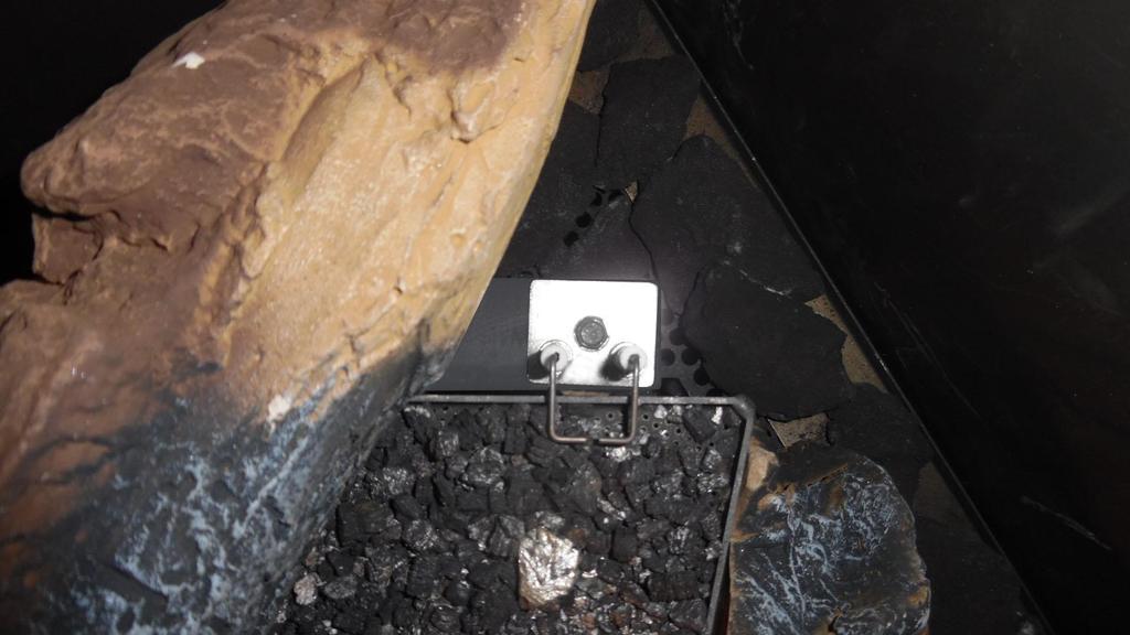
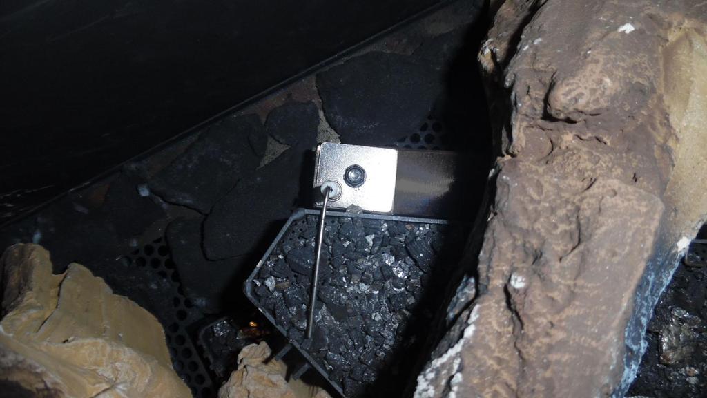
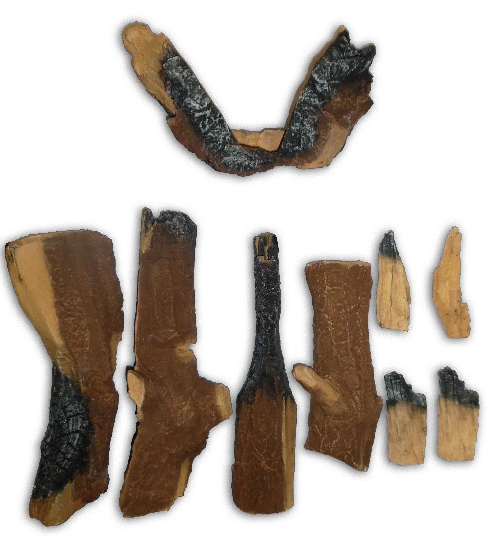
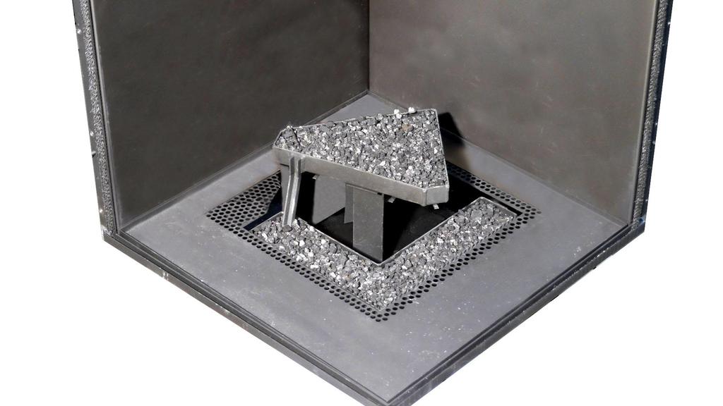
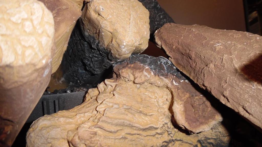
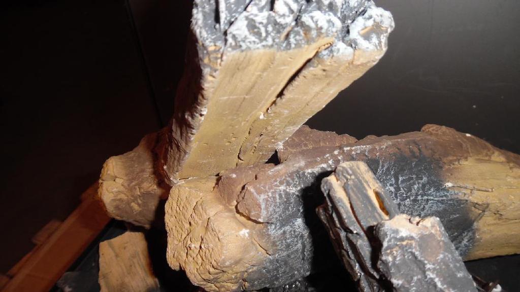
15 5.13 Placing the wood set The appliance is supplied with a wood set. The figures do not always show the correct colours. Observe the instructions below to prevent unsafe situations: Only ever use the supplied wood set. Place the wood set exactly as described. Make sure the ionization and ignition electrodes and the surrounding space remain free (see appendix 3, fig. 9 and 10). make sure there is no vermiculite dust on the burner. Place the logs exactly as described, otherwise: the main burner will not ignite properly; which could result in unsafe situations. the appliance will become filthy more quickly, as a result of soot. the flame picture is affected. The wood set consists of a number of logs (see appendix 3, fig. 13), vermiculite (see appendix 3, fig. 11) and chips (see appendix 3, fig. 12). Place logs as follows Fill the burners with vermiculite (see appendix 3, fig. 14). Place the central log (see appendix 3, fig. 15 ()). aution! lways place the central log first, before placing the chips on the vermiculite tray. Place the chips (see appendix 3, fig. 15) on the vermiculite tray. Then place the other logs as indicated in appendix 3, fig. 16 and 17. Move log towards the rear until it lies against the cam on log. If log D is in the flame, it could be moved a fraction towards the front or rear, so that the flame is not disturbed. 15
16 6. ontrol The appliance is supplied with a wireless black remote control for the user (see appendix 3, fig. 35 ()). s an option, an orange remote control can be supplied for the installer (see appendix 3, fig. 35 (O). ontrolling the flame height, igniting and switching off take place through the black remote control controlling the receiver. Some fires can also be controlled in an alternative way. These options are described further down in this chapter. The user manual describes the operation of the appliance, including the operation of the remote control and alternative methods of operation. Do not ignite the appliance before the gas, discharge and electric connections have been fully installed, first observe the procedure described in chapter 7.3. hapter 6 of the manual supplied applies to an appliance equipped with the M system. 6.1 Remote controls lack remote control for the user Proceed as follows to make the black remote control ready for use: Place the two penlite batteries () in the battery holder of the remote control. Make sure the voltage of the atmospheric fire is not switched off for longer than 5 minutes. If the remote control does not have the "ND" state, the following operations must be performed: Press the menu button (button with square symbol) on the remote control for at least 10 seconds and then press a few times until ND appears on the screen with the receiving symbol. Press the arrow up and arrow down buttons briefly and simultaneously, so that a (flashing) warning triangle and an hourglass appear in the screen as well. s soon as logging on is finished, the start screen will appear!tip le functions are extensively explained in the supplied user manual Orange remote control for the installer y means of the optionally available orange remote control, it is possible to read all information stored in the receiver. In this way, the last 20 error messages can be retrieved, and it will also be possible to read how many times an error occurred. Moreover, this remote control can also be used to adjust the basic settings and to read the size of the ionization flow. It is also required for a wired Domotics control. 6.2 lternative control (if applicable) In addition to the remote control, it is also possible to operate the fire in alternative ways. For this purpose, a Domotics system can be connected to the receiver. This can be a wired or a wireless system. The various possibilities are described below (see appendix 3, fig. 35, 36 and 37) Wired Wired connection of the Domotics system to the receiver takes place via a 0-3VD direct current (see appendix 3, fig. 36 (D)). Tip! higher voltage than 3V will damage the receiver and is therefore not permitted. In case of Domotics systems with an output voltage of 0-10V, you should switch the voltage back to 0-3VD. Use a voltage distributor made of resistors. For example, 2200 ohms and 680 ohms. The voltage above 680 ohms resistance can be used on the input of the 0-3VD. Low ohmic resistors must be used. y controlling the height of the voltage, the receiver will be able to calculate the position of the fire. Table 1 in appendix 3, fig. 37 shows the relationship between the voltage and the height of the flame. If you have an appliance with 2 burners, table 2 will apply. It shows the relationship between the voltage, the height of the flame and the number of burners. Proceed as follows when connecting the Domotics system to the receiver: onnect the 0-3VD signal to the connector, to which a black and yellow wire are connected (see appendix 3, fig. 36 (D)). Use the orange remote control to select the option for a wired connection: go to position 8 in the first menu and select an appliance with single burner (option 2) or an appliance with two burners (option 3). For this, read the manual of the orange remote control.
17 The yellow wire is the + pole, the black wire is the - pole. lways connect - to - and + to Wireless The wireless connection is divided into 2 types: onnection via a modbus protocol. ontrol via an application. Only 1 type of wireless connection is possible on the communication module onnection via modbus protocol Wireless connection of a Domotics system to the receiver is possible via a connection according to the modbus protocol. Such a connection can only be established with a communication module (see ppendix 3, fig. 35 (W)). This module can be ordered from DRU. This communication module translates the modbus protocol from the Domotics system into a wireless signal to the receiver. When connecting a Domotics system via the communication module to the receiver, proceed as follows: Use the remote control to test whether the location where the communication module will be placed is within the reach of the receiver. Place the remote control on this location and test the reception sensitivity (RSSI). Press the on/off button and down arrow at the same time. The value that is now visible, must be between -20 and -70 (see User Manual, "Reception Sensitivity"). If needed, hold the remote control closer to the appliance in order to improve the reception. onnect the communication module by means of an RJ45 plug, according to the instructions in the manual that is supplied with this module. Now follow the steps described in the modbus protocol manual. It is available from the supplier of the domotics system ontrol via application lso when operating the appliance via a tablet provided with the DRU ontrol pp (ios or ndroid), you will need a communication module. This module can be ordered from DRU. In order to control the fire via an application, proceed as follows: Using the remote control, test whether the location where you want to place the communication module is within the receiver's range. Place the remote control on this location and test the reception sensitivity (RSSI). Press the on/off button and down arrow at the same time. The value that is now visible, must be between -20 and -70 (see User Manual, "Reception Sensitivity"). If needed, hold the remote control closer to the appliance in order to improve the reception. onnect the communication module by means of an RJ45 plug, according to the instructions in the manual that is supplied with the communication module. Use the instructions for the application in order to install it. The DRU ontrol app functions in accordance with the multicast and communication protocol. Ensure the router is equipped with this. For this, consult the router's installation manual. If the DRU ontrol app is used, the thermostat function no longer applies. The application 'DRU ontrol' is available in the ppstore, at GooglePlay or our website:
18 7. Final inspection In order to check whether the appliance is working properly and safely, you must perform the following inspections before the appliance is put into operation. 7.1 Gastightness ll connections must be gastight. heck the connections for gastightness. The gas control may be subjected to a maximum pressure of 50 mbar. 7.2 Gas pressure/line-pressure The burner pressure is set at the factory; see data plate. The line-pressure in house installations must be checked, because it can be wrong. heck the line-pressure; see ppendix 3, Fig 38 (P1) for the measuring nipple on the gas control. ontact the gas company if the line-pressure is too high. If the line-pressure is too low, check this at the gas meter. ontact the gas company if the line-pressure is also too low at the gas meter. 7.3 Ignition main burner For igniting the main burner, see the User Manual First ignition of the appliance after installation or adjustments. fter installation, or after work has been performed, you should ignite the appliance for the first time without the glass window. If necessary, bleed the gas pipe. Follow the procedure described below: If necessary, remove the glass pane. Start the ignition procedure as described in the user manual. If the main burner does not ignite: Reset the system by pressing the buttons arrow up and arrow down simultaneously. Repeat the ignition procedure until the main burner ignites; fter each attempt to ignite, the system should be reset by means of the remote control. onsult the diagram with error messages (ppendix 1) if this does not succeed after a few attempts; The appliance ignites at 50%. fter ionization has been detected, the appliance will modulate to 100%. This detection will have to take place within 15 seconds, or else the appliance will enter error mode. If applicable, the second valve will switch to ignite the second burner. Here, you can hear a clear click sound. heck whether the main burner continues to burn. If the main burner does not continue to burn: Reset the system as described and repeat the ignition procedure until the main burner continuous to burn. The system can be reset and re-ignited three times in a row at maximum. Then the system will enter a hard lock-out and you will have to wait half an hour, before you can make a new attempt. onsult the malfunction search diagram (ppendix 1) if this does not happen after a few attempts. Switch off the appliance. Then mount the glass window as described from chapter 5.9. Repeat the ignition procedure a few times and perform the checks described in chapter From now on, the main burner should ignite smoothly. lean the glass pane after igniting for the first time (see section 8).!Tip When checking whether the main burner continuous to burn, it is possible that it switches off after 15 seconds. In that case, this will be caused by the fact that there is no ionization detection and because the glass window has not been placed. This can be regarded as a situation where the main burner continues to burn.
19 lways wait 5 minutes before re-igniting the appliance. No changes may be made to the gas control Main burner The ignition electrode should ignite the main burner within a couple of seconds and without popping. The main burner(s) must cross the full burner smoothly and without popping and continue to burn. If the appliance does not ignite after three restarts and enters hard lockout, it may never be reset by disconnecting it from the power supply. If a restart is necessary after all: remove the glass pane and make sure the gas is able to escape from the appliance. fter this, the appliance may be disconnected from the power supply for 10 seconds. fter these 10 sec., the power supply may be reconnected. Ignite the appliance in the same way as the first ignition, as indicated in section heck operation of the main burner from a cold condition. If sparks are determined between the ignition electrodes, the main burner should burn within a few seconds.!tip The flame picture and a good flame transfer can only be properly judged if the glass window is installed. Use the malfunction search diagram (ppendix 1) if the ignition of the main burner does not comply with the above-mentioned requirements. 7.4 Flame picture The flame picture can only really be assessed when the appliance has been burning for several hours. Volatile components from paint, materials, etc., which evaporate in the first hours, will affect the flame picture. heck whether the flame picture is acceptable. onsult the malfunction search diagram (ppendix 1) if the flame picture is not acceptable, in order to solve the problem. 8. Maintenance Once per year, the appliance must be checked, cleaned and, if necessary, repaired by a competent installer in the field of gas heating and electricity. heck at least whether the appliance is working properly and safely. lose the gas tap when performing maintenance work. heck the gastightness after repair. Make sure there is no voltage on the appliance. lean glass pane(s), if necessary. Only clean a glass pane once it has reached room temperature. aution! void damage to the glass pane(s). void/remove fingerprints on the glass pane(s), as they will burn into the glass. Only clean glass pane(s) with DRU glass pane cleaner, as other agents may damage and/or deteriorate the glass pane(s). For more information, visit our website or ask your dealer. Only use a microfibre cloth. Other materials such as (kitchen) paper, steel wool, etc. may cause scratches and damage the coating in case of anti-reflective glass pane(s). Regularly remove accumulated dirt, as it can burn into the glass. Do not use the appliance when a pane is broken and/or cracked, until it has been replaced as described from section 5.9. If necessary, place back the wood or pebble set correctly; for this, see from section 5.9. Inspect the flue gas discharge system. You must always perform a final inspection. Perform the inspection as described in chapter 7.
20 8.1 Parts omponents that have to be replaced are available at the supplier. 9. Delivery You must explain to the user how to operate the appliance. You must give him/her instructions on putting it into operation, the safety measures, the operation of the remote control and the annual maintenance (see the User Manual). Tell the user to close the gas tap immediately in case of malfunctions/bad performances and contact the installer in order to prevent dangerous situations. hapter 9 of the manual supplied applies to an appliance equipped with the M system. Indicate the location of the gas tap. Point out the precautions in the user manual against unintended ignition by other wireless remote controls such as car keys and garage door openers. Point out the 230 Volt connection. Instruct the user about the appliance and the remote control. When the appliance is taken into operation, point out that In order to avoid cracks in a chimney breast made of stone-like materials or finished with plaster, it should dry for at least 6 weeks prior to putting the appliance into operation. When the appliance is stoked up for the first time, volatile components evaporate from paint, materials, etc.. (lso first read chapter 3 of the user manual!). When evaporating, the appliance should preferably be set at the highest level. The room should be well ventilated. leaning the glass pane(s). Give the manuals to the user (all manuals should be stored near the appliance). 10. Malfunctions ppendix 1 provides an overview of malfunctions that might occur, their possible causes and remedies.
21 ppendix 1 Malfunctions Error messages Error code Problem Possible cause Remedy F01 ommunication loss between receiver and burner device ommunication cable does not make contact Make sure the connectors of the communication cable make proper contact F02 Receiver overheated (60 above room temperature) ommunication cable defective Poor ventilation at receiver Replace communication cable Improve ventilation at receiver Receiver makes contact with hot parts Move receiver in such a way that there is no more contact with hot parts F03 Internal (receiver) NT sensor does not work correctly Receiver is defective Replace the receiver F04 External NT sensor, does not work correctly External NT sensor or cabling defective. Replace NT sensor or replace cabling F05 Internal safety error Receiver is defective Replace receiver F06 ommunication loss between transmitter and receiver Transmitter is out of the receiver's range Make sure the transmitter is near the receiver Obstacles between transmitter and receiver may interfere with the signal Remove possible obstacles between transmitter and receiver Transmission power is too weak heck transmission power (see User Manual chapter 10) F08 No ionization No sparks Make sure distance between electrodes is 3-4 mm Replace spark electrodes No gas heck whether there is gas When using PowerVent, check whether the gas valve opens Poor flame transfer main burner heck position blocks/chips If necessary, remove dust from burner openings No good flame under ionization pin (suffocating flame) Glass pane strips not placed correctly heck restriction and air inlet guide setting When using PowerVent, check pressure setting Ionization pin placed incorrectly Place it on the right location Ionization pin blocked (measure ionization flow when > 0 and < 1.8 u) Remove any vermiculite or chips from the burner 21
22 Error messages Error code Problem Possible cause Remedy F08 (follow-up) F12 ESYS is not released Ionization pin defective (measure ionization current when 0) ESYS is in hard-lock Replace the ionization pin Wait half hour until ESYS resets itself. F13/F14 (ionisation <0.8 µ) Flame loss when only the main burner (F13) is on or both burners (F14) are on Ionisation pin short-circuited Remove chips, vermiculite or glow material lying against the ionisation pin Ionisation current too critical (0.8 Iionisation < 1.8 µ) Increase ionisation current to 1.8 µ by rearranging vermiculite, and removing chips and dust from the burner openings Suffocation due to poor flue gas channel heck the concentric system heck the setting of the appliance Suffocation when using PowerVent heck the pressure setting of the PowerVent system 24 hour check control (only in case of F13) Reset with remote control (consult Powervent manual) Gas has fallen away heck gas supply Gas control defective (see "" in app. 3, fig. 38) Replace the gas control F15 No burner device (see "" in appendix 3, fig. 38) urner device came loose from burner device ttach the burner device urner device incorrectly mounted Mount the burner device correctly Pins on the connector on the gas control are bent end them straight High limit error High limit bridge defective heck High limit bridge ESYS F16 Hardware Error ESYS ESYS defective (burner device) Replace ESYS (burner device) F17 Disable contact is closed Window is open. (if this contact is present) lose window bridge has been made across the Disable contact. Remove bridge on ESYS (burner device)
23 ppendix 2 Tables Table 1: Parts included with the delivery Part Wood set ontrol hatch ontrol hatch manual Installation manual User manual Remote control Gauge for restrictor slide Restrictor slide ack-up self-tapping screws for benefit of glass pane assembly Key bolts M8x 140x50 Hexagonal nut M8 Washer M8 Stop Nut M10 djustable foot ompression fitting 15mm x G3/8" over plate air inlet guide Socket spanner 8 mm Mains lead Number 1x 1x 1x 1x 1x 1x 1x 1x 6x 4x 4x 4x 4x 4x 4x 1x 1x 1x 1x
24 Product name Type of appliance ombustion Supply and discharge system Flame protection version tmosphere safety Explosion hatch Ventilation hole chimney breast Type Table 2: Technical data Paco RH uilt-in losed combustion oncentric 150/100 Separated ignition / ionization plugs No Yes 200 cm 2 11/31/91 Type of gas Nominal output Nominal heat input (Hi) Nominal heat input (Hs) onsumption max onsumption min urner pressure max urner pressure min urner injector Low setting injector Efficiency class * = djusting screw kw kw kw L/h L/h mbar mbar mm mm mm ode G ø1.65 ø1.40 * 2 G25/G ø1.65 ø1.40 * 2
25 Table 3: Line-pressure when using G31 ountry mbar Permissibility and conditions concentric system with wall terminal Table 4: onditions for setting the appliance G20/G25/G25.3 Total number of meters vertical pipe length Total number of meters horizontal pipe length (excluding wall terminal) See Figure ir inlet guide Restrictor slide Distance of restriction in mm NO YES ) >0-2 5 NO NO OPEN NO YES 50 1 >0-1 5 NO YES 58 1 >1-3 5 NO NO OPEN 1) factory setting 25
26 Table 5: Determining permissibility concentric system with roof terminal G20/G25/G25.3 Total number of meters horiz. pipe length Total no. of meters vertical and/or sloping pipe length no bends 2 bends 3 bends 4 bends 5 bends = Situation is not permissible minimum length Situation ir inlet guide NO YES YES Table 6: onditions for the adjustment of the appliance with a roof terminal Restrictor slide NO YES YES Distance restrictor. in mm OPEN G20/G25/G25.3
27 ppendix 3 Figures min. 17 max. 55 min max min. 463 max c-1148 /1 2a 2b max ,5 380,5 100* max * 55* 50* min. 460 max of * 275* min. 460 max * x 15 of * 275* x 38c-1155b 38c-1156b
28 2c 2d Y X 2 38c c e (17) (18) (16) (19) 15 (15) * 100* 38c * 275* 50* 275*

29 2f (18) (17) (16) (19) 15 (15) * 98* 38c * 55* 275* 55* 2g P Q 10 38P-0613 /0
30 2h 2i L M M K L 38c c E H G F D b /0
31 d / x90 0-2m 1x90 0-3m 0.5m 1m ZV J
32 6 1 38c /0


33 P-0619/ c-1149/0 38P-0620/ p p
34 13 38P-0617/0 G H D E F 14 38P-0614/0


35 15 38P-0615/0 16 D H F G 38P-0616/0 E F


36 17 D H F E 38P-0618/0 F G V D O Modbus W R WiFi Router /0

37 36 L N 38p-0320 /0 L N D + L N 0 3V 37 U 1 І І І І І І І І І І І І І І 1,98 Off > О 1,98 Off > О О О U 2


38 38 P1 P2 D G (IN) 38p-0319 / Min. 0 mm Min. 0 mm / /0 Min. 12,5 mm Min. 12,5 mm Min. 60 mm Min. 60 mm Min. 100 mm Min. 100 mm
Metro 130XT 41 RCH Metro 130XT Tunnel 41 RCH
 Metro 130XT 41 RH Metro 130XT Tunnel 41 RH G20/G25/G25.3 (Natural gas) G31 (Propane) Installation manual Store this document in a safe place 959.073.02.EN DRU-667777-EN-US-1017-3 EN ontents 1. Introduction
Maestro 80-2 RCH Maestro 80-3 RCH
 Maestro 80-2 RH Maestro 80-3 RH G20/G25/G25.3 (Natural gas) G31 (Propane) Installation manual (/IE) Store this document in a safe place 959.094.04. DRU-677279-EN-US-1016-5 INSTLLTION MNUL ontents 1. Introduction
Circo RCE G20/G25/G25.3/G31. Installation manual. English. Store this document in a safe place DRU EN-US
 irco RE G20/G25/G25.3/G31 Installation manual Store this document in a safe place 959.044.02.UK DRU-175417-EN-US-1017-4 EN INSTLLTION MNUL ontents 1. Introduction 2. E declaration 3. SFETY 3.1 General
PowerVent. Installation manual (GB) English. Store this document in a safe place UK
 English. Store this document in a safe place UK") PowerVent Installation manual (GB) Store this document in a safe place 959.034.03.UK GB Contents Blz Foreword 3 1. Introduction 3 2. CE declaration 4 3. SAFETY 4 3.1 General 4 3.2 Regulations 4 3.3 Precautions
PowerVent Installation manual (GB) Store this document in a safe place 959.034.03.UK GB Contents Blz Foreword 3 1. Introduction 3 2. CE declaration 4 3. SAFETY 4 3.1 General 4 3.2 Regulations 4 3.3 Precautions
Circo G20/G25/G31. Installation manual (GB/IE) English. Store this document in a safe place DRU EN
 English. Store this document in a safe place DRU EN") irco G20/G25/G31 Installation manual (G/IE) Store this document in a safe place 959.044.01. DRU15798-175417-EN--0213-2 INSTLLTION MNUL ontents 1. Introduction 2. E declaration 3. SFETY 3.1 General 3.2
irco G20/G25/G31 Installation manual (G/IE) Store this document in a safe place 959.044.01. DRU15798-175417-EN--0213-2 INSTLLTION MNUL ontents 1. Introduction 2. E declaration 3. SFETY 3.1 General 3.2
PowerVent. Installation manual (GB) English. Store this document in a safe place UK
 English. Store this document in a safe place UK") PowerVent Installation manual (GB) Store this document in a safe place 959.078.00.UK GB Contents page Foreword 3 1. Introduction 3 2. CE declaration 4 3. SAFETY 4 3.1 General 4 3.2 Regulations 4 3.3 Precautions
PowerVent Installation manual (GB) Store this document in a safe place 959.078.00.UK GB Contents page Foreword 3 1. Introduction 3 2. CE declaration 4 3. SAFETY 4 3.1 General 4 3.2 Regulations 4 3.3 Precautions
Metro 130 XT Metro 130 XT Tunnel
 Metro 130 XT Metro 130 XT Tunnel G20/G25/G31 Installation manual (G/IE) Store this document in a safe place 959.041.00. DRU15798-112731-EN--0113-2 INSTLLTION MNUL ontents 1. Introduction 2. E declaration
User manual (GB / IE) for appliances provided with an electronic ignition on the remote control. English. Read this document and store it carefully
 for appliances provided with an electronic ignition on the remote control. English. Read this document and store it carefully") User manual (GB / IE) for appliances provided with an electronic ignition on the remote control Read this document and store it carefully 958.007.07.uk 1 UK Contents page Preface 2 1. Introduction 3 2.
User manual (GB / IE) for appliances provided with an electronic ignition on the remote control Read this document and store it carefully 958.007.07.uk 1 UK Contents page Preface 2 1. Introduction 3 2.
PowerVent Installation manual. English. Store this document in a safe place EN
 PowerVent - 02 Installation manual Store this document in a safe place 959.114.01.EN en Contents Page Foreword 3 1. Introduction 3 2. CE declaration 4 3. SAFETY 4 3.1 General 4 3.2 Regulations 4 3.3 Precautions
Trio RCE. G20/G25/G25.3 (natural gas) Instructions for installation. English. Please retain this document carefully EN
 Instructions for installation. English. Please retain this document carefully EN") Trio RCE G20/G25/G25.3 (natural gas) Instructions for installation Please retain this document carefully 959.064.04.EN EN Contents page Preface 2 1. Introduction 3 2. CE Declaration 3 3. SAFETY 3 3.1 General
Trio RCE G20/G25/G25.3 (natural gas) Instructions for installation Please retain this document carefully 959.064.04.EN EN Contents page Preface 2 1. Introduction 3 2. CE Declaration 3 3. SAFETY 3 3.1 General
Clear Installation guide
 Clear 40010631-0938 ENG Installation guide ENG 1.1 1.2 1.3 A 1.4 1.5 1 < < < < A B 2.1 2.2 2.3 C 2.4 2.5 2 < < < < 3.1 3.2 3-3 3 < < < < Inhoudsopgave 1 Introduction... 6 2 Safety instructions... 6 3 Installation
Solution Installation guide
 Solution 40011444-1327 ENG Installation guide ENG 1-1 1-2 1-3 1.4 1 < < < < 2.1 2-3 2-4 2 < < < < 3-1 3.2 3-3 3.5 3.6 3 < < < < 4-1 A 4-2 4-3 4 < < < < Dimensions Terminal position Distance (For good working
Duet XL /0929. Installation guide
 Duet XL 40010749/0929 ENG Installation guide ENG 1.1 1.2 1.3 1.4 1.5 A 1.6 1.7 1 < < < < B A 2.1 2.2 2.3 2.4 2 < < < < 2.5 2.6 2.7 2.8 3 < < < < 3.1 F F 3.2 3.3 4 < < < < Table of contents 1 Introduction...
Metro 70 - Metro 70 Tunnel
 Metro 70 - Metro 70 Tunnel G31 propane Instructions for installation (GB / IE) Please retain this document carefully UK Contents page Foreword 2 1. Introduction 3 2. EC Declaration of Conformity 3 3. SAFETY
Fyn Installation guide
 Fyn 600 4001131-1123 ENG Installation guide ENG 1.1 1.2 A B 1.3 1.4 1 < < < < 2.1 2.2 2.3 2.4 3.1 3.2 2 < < < < 4.1 4.2 4.3 4.4 3 < < < < 1 Introduction The appliance can only be installed by a competent
Fyn Installation guide
 Fyn 450 400100929-1114 ENG Installation guide ENG 1.1 1.2 A B 1.3 1.4 1 < < < < 2.1 2.2 2.3 3.1 3.2 2 < < < < 4.1 4.2 4.3 4.4 3 < < < < Table of contents 1 Introduction... 6 2 Safety instructions... 6
Respect OC Installation manual
 Respect OC 40011335-1235 ENG Installation manual ENG 1.1 1.2 A 1.3 1.4 A A 2.1 2.2 2.3 1 < < < < 2.4 2.5 B C A B A 2.6 2 < < < < 3.1 3.2 3.3 3.4 3.5 3.6 3 < < < < A B 3.7 4 < < < < L A A 4.1 A A 4.2 A
Duet Premium M Duet Premium M ENG
 Duet Premium M 40011422-1441 Duet Premium M ENG 1.1 1.2 1.3 1.4 1.5 1.6 1.7 1.8 1 < < < < 2.1 a 2.1 b 2.1 c A C 2.2 2 < < < < F F 2.3 X H X C 2.4 2.5 S T 3.1 3.2 R Q 3.3 3 < < < < 4.1 4.2 4.3 4.4 4 <
Relaxed Premium M Relaxed Premium M ENG
 Relaxed Premium M 40010959 1440 Relaxed Premium M ENG 3 alternative finishes. 1.1a 1.1b 1.1c 1 < < < < 1.2 1.3 7 1.4 2 < < < < 1.5 1.6 B 1.9 3 < < < < 2.1 2.2 2.3 3.1 3.2 3.3 3.4 4 < < < < 3.5 4.1 4.2
Vaska Logburner. voorbeeld Installation guide
 Vaska ogburner voorbeeld 40010627-2103 ENG Installation guide ENG 1.1 1.2 1.3 1.4 1.5 1 < < < < 1 Introduction The appliance can only be installed by a competent person in accordance with the Gas Safety.
SAFIRE 2000A FUEL OIL HEATER INSTALLATION, OPERATION AND MAINTENANCE
 SAFIRE 2000A FUEL OIL HEATER INSTALLATION, OPERATION AND MAINTENANCE You have selected the new generation SAFIRE oil heater as your heating solution. Although our goal is to take into account all problems
Installation Manual EF5000 AUS & NZ
 Installation Manual EF5000 AUS & NZ This manual is ONLY for fires with a serial No. from 80600 to 80999. Important: The appliance shall be installed in accordance with; Local gas fitting regulations Municipal
Duet Premium L Duet Premium L ENG
 Duet Premium L 40011297-1441 Duet Premium L ENG 1.1 1.2 1.3 1.4 1.5 1.6 1.7 1.8 1 < < < < 2.1 a 2.1 b 2.1 c A C 2.2 2 < < < < F F 2.3 X H X C 2.4 2.5 S T 3.1 3.2 R Q 3.3 3 < < < < 4.1 4.2 4.3 4.4 4 <
Installation Manual EF5000 NZ
 Installation Manual EF5000 NZ Important: The appliance shall be installed in accordance with; Local gas fitting regulations Municipal building codes AS/NZS 5601.1.1:2010 Gas Installation Any other relevant
User s Information Manual
 48AJ,AK,AW,AY020-060 Single-Package Rooftop Gas Heating Units with COMFORTLINK Controls and Scroll Compressors User s Information Manual NOTE TO INSTALLER This manual should be left with the equipment
This document was created with FrameMaker 4.0.4
 This document was created with FrameMaker.0. WELCOME TO TODAY S GENERATION OF COMFORT Congratulations! Your new, higher efficiency gas furnace is a sound investment which will reward you and your family
FIREPLACE INSTALLATION
 CHECK GAS TYPE Use proper gas type for the fireplace unit you are installing. If you have conflicting gas types, do not install fireplace. See retailer where you purchased the fireplace for proper fireplace
CRYSTAL FIRES. Inset Conventional Flue Fire. (BOSTON/MIAMI) Cf1 and MANHATTAN USER INSTALLATION AND SERVICING INSTRUCTIONS
 Cf1 and MANHATTAN USER INSTALLATION AND SERVICING INSTRUCTIONS") CRYSTAL FIRES (BOSTON/MIAMI) Cf1 and MANHATTAN Inset Conventional Flue Fire USER INSTALLATION AND SERVICING INSTRUCTIONS FOR USE WITH NATURAL GAS G20 @ 20 mbar For use in GB and IE CE THESE INSTRUCTIONS
CRYSTAL FIRES (BOSTON/MIAMI) Cf1 and MANHATTAN Inset Conventional Flue Fire USER INSTALLATION AND SERVICING INSTRUCTIONS FOR USE WITH NATURAL GAS G20 @ 20 mbar For use in GB and IE CE THESE INSTRUCTIONS
Installation manual Anna. In combination with the Smile T230. Manual PW version 2.0
 Installation manual Anna. In combination with the Smile T230. Manual PW version 2.0 Hello Anna. Before there were thermostats. Now there is Anna. Anna works for you and does what she is supposed to do:
Internet Version for Reference Only INDUCED DRAFT COMMERCIAL WATER HEATERS SUPPLEMENT INSTRUCTIONS TO PART #
 INDUCED DRAFT COMMERCIAL WATER HEATERS SUPPLEMENT INSTRUCTIONS TO PART #238-39387-00 THIS INSTRUCTION SUPPLEMENT IS ONLY INTENDED TO GIVE INSTALLATION INSTRUCTIONS AND INFORMATION RELATED TO THE INDUCED
Installation Instructions Horizon Natural Draft Electronic Ignition Gas Fireplaces
 Installation Instructions Horizon Natural Draft Electronic Ignition Gas Fireplaces Installation Instructions Horizon Natural Draft Electronic Ignition 3 Sided Gas Fireplaces Natural Draft Electronic Ignition
GLOBAL 40 CF FITTING INTO A CONVENTIONAL CLASS 1 CHIMNEY
 INSTALLATION INSTRUCTIONS GB/IE GLOBAL 40 CF FITTING INTO A CONVENTIONAL CLASS 1 CHIMNEY DRU VERWARMING B.V. HOLLAND 957.669.00 CONTENTS Site: 3 Important 3 Foreword 4 Instructions for installation 4 Ventilation
Operating instructions
 Operating instructions Gas condensing boiler WARNING: If the information in this manual is not followed exactly, a fire or explosion may result causing property damage, personal injury or loss of life.
Fig. 1 - Unit PGD4, PGS4, WPG4
 OWNER S MANUAL 14 SEER Single -Package Air Conditioner and Gas Furnace System with R -410A Refrigerant Single Phase 2 to 5 Nominal Tons Three Phase 3 to 5 Nominal Tons PGD4andPGS4SeriesE,WPG4SeriesB Fig.
Packaged Gas/Electric Units. Owner s Guide to Operating and Maintaining Your Gas/Electric Unit
 Packaged Gas/Electric Units Owner s Guide to Operating and Maintaining Your Gas/Electric Unit ELECTRICAL SHOCK HAZARD. FIRE OR EXPLOSION HAZARD Disconnect power at fuse box or service panel before performing
INSTALLATION AND OPERATION INSTRUCTIONS FOR
 INSTALLATION AND OPERATION INSTRUCTIONS FOR BI-40-DEEP-XT BI-50-DEEP-XT BI-60-DEEP-XT BI-72-DEEP-XT BI-88-DEEP-XT SAFETY INFORMATION WARNING If the information in these instructions are not followed exactly,
Fully-automatic Gas tankless Water Heater USER'S MANUAL FOR MODEL EZ-101 ISO9001 certified
 Fully-automatic Gas tankless Water Heater USER'S MANUAL FOR MODEL EZ-101 ISO9001 certified Thank you for purchasing our fully-automatic gas-fired tankless water heater. Please completely read this Manual
Installation and maintenance instructions
 6304 4994 03/2006 GB For installer Installation and maintenance instructions Flue gas heat exchanger WT30/40 Please read thoroughly prior to installation and maintenance. Contents Contents Contents 2 1
User's Infomation Manual
 User's Infomation Manual 574A GAS HEATING/ELECTRIC COOLING Cancels: OM01-69 OM10-28 02-07 NOTE: Read the entire instruction manual before starting the installation. SAFETY CONSIDERATIONS Note to Installer:
Installation Instructions & Operating Manual IMPORTANT
 Installation Instructions & Operating Manual IMPORTANT These instructions should be read carefully and retained for future reference TABLE OF CONTENTS SECTION 1: WARNINGS & ELECTRIC SPECIFICATIONS 1.1
HORIZONTAL COOKING SERIES: 700 / 900 S.A.V MAINTENANCE & AFTER SALES WORK PPS-3WE711911CH
 SERIES: 700 / 900 S.A.V MAINTENANCE & AFTER SALES WORK PPS-3WE711911CH GENERAL Tools Every time you se this symbol it is vital that you have the tool indicated to ensure correct and compliant work is undertaken
INSTALLATION MANUAL. Split-type Air Conditioner (Cooling and Heating) Outdoor Unit UQB09JJWC UQB12JJWC. Indoor Unit AQB09JJWC AQB12JJWC
 Outdoor Unit UQB09JJWC UQB12JJWC. Indoor Unit AQB09JJWC AQB12JJWC") AQB09JJ6WC_IM_E_2585 2006.4.17 4:26 PM Page 17 INSTALLATION MANUAL Indoor Unit AQB09JJWC AQB12JJWC Outdoor Unit UQB09JJWC UQB12JJWC ENGLISH FRANÇAIS ESPAÑOL Split-type Air Conditioner (Cooling and Heating)
AQB09JJ6WC_IM_E_2585 2006.4.17 4:26 PM Page 17 INSTALLATION MANUAL Indoor Unit AQB09JJWC AQB12JJWC Outdoor Unit UQB09JJWC UQB12JJWC ENGLISH FRANÇAIS ESPAÑOL Split-type Air Conditioner (Cooling and Heating)
Heat Exchanger Block Replacement Instructions
 Series 1-4 Gas-fired water boiler Heat Exchanger Block Replacement Instructions Ultra-80 S1-4 Heat Exchanger Block Replacement Kit, Part No. 383-500-773 Ultra-105 S1-4 Heat Exchanger Block Replacement
Servicing manual. Wall-mounted condensing gas boiler 600 Series - 11S / 19S / 24S / 24C /2002 GB(EN) For trade use
 For trade use") GB122 7210 1300-12/2002 GB(EN) For trade use Servicing manual Wall-mounted condensing gas boiler 600 Series - 11S / 19S / 24S / 24C Please read thoroughly before attempting to diagnose fault List of contents
GB122 7210 1300-12/2002 GB(EN) For trade use Servicing manual Wall-mounted condensing gas boiler 600 Series - 11S / 19S / 24S / 24C Please read thoroughly before attempting to diagnose fault List of contents
Owner s Information Manual
 48ES---A and 48VL---A Comfort and Performance 13 and 14 SEER Single Packaged Air Conditioner and Gas Furnace System With Puron (R---410A) Refrigerant Single and Three Phase 2---5 Nominal Tons (Sizes 24---60)
BENSON LINEAR RADIANT TUBE
 BENSON LINEAR RADIANT TUBE Natural or Propane (Gas fired) I N S T A L L A T I O N C O M M I S S I O N I N G S E R V I C I N G U S E R I N S T R U C T I O N S September 2001 CONTENTS Page Compliance Notices
Servicing manual. 600 Series - 11S / 19S / 24S / 24C. Wall-mounted condensing gas boiler. For trade use
 GB122 Servicing manual Wall-mounted condensing gas boiler 600 Series - 11S / 19S / 24S / 24C For trade use Please read thoroughly before attemting to diagnose fault 7217 4900 (03/2010) GB/IE List of contents
Baxi Solaire Super Gas Fire Natural Gas Comp N o /95
 Please leave these Instructions with the user. Baxi Solaire Super Gas Fire Natural Gas Comp N o 236216-10/95 Baxi Solaire Super - G.C.N o 32 077 36 Installation And Servicing Instructions Installation
Installation and maintenance instructions
 6304 4995 0/004 GB For installer Installation and maintenance instructions Flue gas heat exchanger WT50/60 Please read thoroughly prior to installation and maintenance. Summary About this manual This equipment
Ca 6s and BCa 6s kw INSTALLATION AND OPERATING INSTRUCTIONS. Page 1 31/07/00
 Ca 6s and BCa 6s 33-64 kw INSTALLATION AND OPERATING INSTRUCTIONS Page 1 CONTENTS: General specification Dimensions for Ca6s and BCa6s boilers. Boiler room clearance requirements Boiler block assembly
VASKA C11. gas-fireplace user manual. Saturnus 8 NL-8448 CC Heerenveen Postbus 219 NL-8440 AE Heerenveen T. +31(0) F.
 F.") VASKA C11 gas-fireplace user manual Saturnus 8 NL-8448 CC Heerenveen Postbus 219 NL-8440 AE Heerenveen T. +31(0)513 656500 F. +31(0)513 656501 40 010 458 01.51 DESCRIPTION OF THE FIREPLACE CONTENTS 1 2
VASKA C11 gas-fireplace user manual Saturnus 8 NL-8448 CC Heerenveen Postbus 219 NL-8440 AE Heerenveen T. +31(0)513 656500 F. +31(0)513 656501 40 010 458 01.51 DESCRIPTION OF THE FIREPLACE CONTENTS 1 2
Owner s Manual. Induced Combustion Gas Furnace ! WARNING NOTE TO INSTALLER: THIS MANUAL MUST BE LEFT WITH THE EQUIPMENT USER.
 Induced Combustion Gas Furnace NOTE TO INSTALLER: THIS MANUAL MUST BE LEFT WITH THE EQUIPMENT USER. Owner s Manual CERTIFIED USER: Please read all instructions in the manual and retain all manuals for
PrecisionTemp Shower-Mate
 Shower-Mate Instantaneous Gas Water Heater Installation and Operating Instructions The Shower-Mate is a power vented automatic instantaneous water heater designed to be installed in ventilated marine applications.
User s Information Manual
 62DA,DB,DC,DD07-38 Vertical or Horizontal Dedicated 100% Outdoor Air Unit with Optional Gas Heat User s Information Manual NOTE TO INSTALLER This manual should be left with the equipment owner. : If the
User Guide Compact-7 series
 User Guide Compact-7 series Boiler-CH Calorifier Combi Introductory remarks Congratulations on the purchase of your Kabola Compact 7. Kabola has been a manufacturer of oil-fired heating systems since 1947.
Installation manual Anna. In combination with the Smile T. Manual PW version 2.0
 Installation manual Anna. In combination with the Smile T. Manual PW version 2.0 Hello Anna. Before there were thermostats. Now there is Anna. Anna works for you and does what she is supposed to do: create
Hestia Installation Guide
 Hestia 40010610-0746 UK Installation Guide Content 1.1 1.2 1.3 1.4 A B C D 1.5 1.6 1 < < < < Hestia with Wirdum Surround 2.1 2.2 2.3 2.4 2.5 2.6 > > > > 2 Hestia with Jellum Surround 3.1 3.2 3.3 3.4 3.5
SIERRA RADIANT HEAT MAJESTIC OAK VENTED GAS LOG KIT INSTALLATION AND OPERATING INSTRUCTIONS
 SIERRA RADIANT HEAT MAJESTIC OAK VENTED GAS LOG KIT INSTALLATION AND OPERATING INSTRUCTIONS WARNING: If the information in this manual is not followed exactly, a fire or explosion may result causing property
User s Information Manual
 48N2,N3,N4,N5,N6,N7,N8,N9 75-150 Ton Gas Heating/Electric Cooling Units with ComfortLink Controls User s Information Manual NOTE TO INSTALLER: This manual should be left with the equipment owner. : If
IDE 20 / IDE 30 / IDE 50 IDE 60 / IDE 80
 IDE 20 / IDE 30 / IDE 50 IDE 60 / IDE 80 EN OPERATING MANUAL OIL HEATER TRT-BA-IDE20-30-50-60-80-TC-001-EN Table of contents Information on the use of this manual... 1 Scope of delivery... 1 General safety...
INSTALLATION, USERS AND SERVICING INSTRUCTIONS
 INSTALLATION, USERS AND SERVICING INSTRUCTIONS SLIMLINE (FAN FLUE) HOTBOX Inset Decorative coal or pebble effect Gas Fire For use with Natural Gas (G20) @ 20mbar or Butane (G30) @ 28mbar or Propane (G31)
Smart-Wall TV Kit - Installation & Operation Instructions -
 If any parts are missing or damaged, contact your Dealer before starting installation. DO NOT install a damaged kit. Be sure to also reference the appliance Installers Guide. Approvals The flexible duct
INSTALLATION MANUAL. Decoration Panel Provided with Filter Auto Cleaning Function Self Cleaning decoration panel BYCQ140D7GW1 BYCQ140D7GFW1
 INSTALLATION MANUAL Decoration Provided with Filter Auto Cleaning Function Self Cleaning decoration panel BYCQ0D7GW BYCQ0D7GFW BYCQ0D7GW BYCQ0D7GFW Installation manual Contents. SAFETY PRECAUTIONS....
USER MANUAL. 60cm, 3 burners, Hob AKC 630
 USER MANUAL 60cm, 3 burners, Hob AKC 630 For your safety These instructions have been drawn up for your safety and that of others. You are therefore requested to read them carefully before installing
SAFIRE 1600D, 1800D and 2100D Diesel / fuel oil heaters USAGE, INSTALLATION AND MAINTENANCE
 SAFIRE 1600D, 1800D and 2100D Diesel / fuel oil heaters 1 Heater kit contains : Heater, mounting bracket Fuel hose (3 meters), pump, a fuel tank connection to standard tanks (15, 22, 30 litres) Power supply
U tube models PTU 09, 12, 15, 25, 30, 35, 40, 45. single linear tube models PTS 09, 12, 15, 25, 30, 35, 40, 45
 U tube models PTU 09, 2, 5, 25, 30, 35, 40, 45 & single linear tube models PTS 09, 2, 5, 25, 30, 35, 40, 45 installation, servicing & operating instructions INSTALLATION, SERVICING AND OPERATING INSTRUCTIONS
VASKA C11. gas -fireplace installation guide
 VASKA C11 gas -fireplace installation guide Saturnus 8 NL-8448 CC Heerenveen Postbus 219 NL-8440 AE Heerenveen T. +31(0)513 656500 F. +31(0)513 656501 40 010 459 01 51 DESCRIPTION OF THE FIREPLACE CONTENTS
HOME OWNER S INFORMATION Induced Combustion Gas Furnace
 HOME OWNER S INFORMATION Induced Combustion Gas Furnace NOTE TO INSTALLER: This manual must be left with the equipment user. USER: Please read all instructions in the manual and retain all manuals for
INSTALLATION MANUAL. Split-type Air Conditioner (Cooling and Heating) Indoor Unit AQB18J6WC AQB24J2WC. Outdoor Unit UQB18J6WC UQB24J2WC
 Indoor Unit AQB18J6WC AQB24J2WC. Outdoor Unit UQB18J6WC UQB24J2WC") AQB8J6WC_IM_E_25864 2006.4.4 3:29 PM Page 7 INSTALLATION MANUAL Indoor Unit AQB8J6WC AQB24J2WC Outdoor Unit UQB8J6WC UQB24J2WC ENGLISH FRANÇAIS ESPAÑOL Split-type Air Conditioner (Cooling and Heating)
AQB8J6WC_IM_E_25864 2006.4.4 3:29 PM Page 7 INSTALLATION MANUAL Indoor Unit AQB8J6WC AQB24J2WC Outdoor Unit UQB8J6WC UQB24J2WC ENGLISH FRANÇAIS ESPAÑOL Split-type Air Conditioner (Cooling and Heating)
VASKA B11. gas -fireplace installation guide
 VASKA B11 gas -fireplace installation guide Saturnus 8 NL-8448 CC Heerenveen Postbus 219 NL-8440 AE Heerenveen T. +31(0)513 656500 F. +31(0)513 656501 40 010 446 01 51 DESCRIPTION OF THE FIREPLACE CONTENTS
CHESNEY S. Bio-Ethanol Installation & User Manual. model: EFB1200 with resevoir. Issue 01
 CHESNEY S Bio-Ethanol Installation & User Manual model: EFB1200 with resevoir Issue 01 1 2 Thank you for choosing this Chesney s Bio-Ethanol fire. Please read this information guide carefully in order
Packaged Gas/Electric
 Packaged Gas/Electric Units Owner's Guide to Operating and Maintaining Your Gas/Electric Unit ELECTRICAL SHOCK HAZARD. FIRE OR EXPLOSION HAZARD Failure to follow this warning can result in Disconnect power
USER S, MAINTENANCE and SERVICE INFORMATION MANUAL
 CONTENTS SAFETY INFORMATION................ 2 FOR YOUR SAFETY....................... 2 SYSTEM OPERATION.................. 2 THERMOSTATS.......................... 2 INTERMITTENT IGNITION DEVICE...........
Installation. Leveling
 Your refrigerator was packed carefully for shipment. Remove and discard shelf packaging and tape. Do not remove the serial plate. Location Do not install refrigerator near oven, radiator or other heat
Bosch 80% AFUE Gas Furnace BGS80 Model
 Bosch 80% AFUE Gas Furnace BGS80 Model 4-Way Multipoise Category I Fan-Assisted Furnace User's Information Manual 3124627 2 Bosch 80% AFUE Gas Furnace User's Information Manual Data subject to change 06.2018
Kalahari DECORATIVE FUEL EFFECT GAS FIRE
 Kalahari DECORATIVE FUEL EFFECT GAS FIRE User Instructions These instructions should be read by the user before operating the appliance and retained for future reference Model No. KRDC00MN & KRDC00SN are
F900 SERIES GAS CHARGRILL G9440, G9460, G9490, G User, installation and servicing instructions T Read these instructions before use
 F900 SERIES User, installation and servicing instructions GAS CHARGRILL G9440, G9460, G9490, G94120 Read these instructions before use DATE PURCHASED: MODEL NUMBER: SERIAL NUMBER: DEALER: SERVICE PROVIDER:
USER'S MANUAL PGE Single Package Rooftop
 USER'S MANUAL PGE Single Package Rooftop Gas Heating/Electric Cooling Units Sizes 036-150 3 to 12-1/2 Tons NOTE TO INSTALLER: This manual should be left with the equipment owner. WARNING: If the information
USER'S INFORMATION MANUAL
 USER'S INFORMATION MANUAL CAST IRON GAS FIRED WATER HEATING BOILERS WARNING: If the information in this manual is not followed exactly, a fire or explosion may result causing property damage, personal
Installation manual for room air conditioner
 Installation manual for room air conditioner HSU-26HEK03/R2(D)/I HSU-35HEK03/R2(D)/I HSU-53HEK03/R2(D)/I HSU-71HEK03/R2(D)/I HSU-26HEK03/R2(D)/O HSU-35HEK03/R2(D)/O HSU-53HEK03/R2(D)/O HSU-71HEK03/R2(D)/O
Installation Instructions T 9822 Gas Dryer. en - US, CA. To prevent accidents
 Installation Instructions T 9822 Gas Dryer To prevent accidents en - US, CA and appliance damage read these instructions before installation or use. M.-Nr. 07 431 110 2 WARNING For your safety the information
Owner's Manual. Induced Combustion Gas Furnace ! WARNING NOTE TO INSTALLER: THIS MANUAL MUST BE LEFT WITH THE EQUIPMENT USER.
 Induced Combustion Gas Furnace Owner's Manual NOTE TO INSTALLER: THIS MANUAL MUST BE LEFT WITH THE EQUIPMENT USER. USER: PLEASE READ ALL INSTRUCTIONS IN THE MANUAL AND RETAIN ALL MANUALS FOR FUTURE REFERENCE.
INSTALLATION AND OPERATION INSTRUCTIONS FOR BI-DEEP UNITS
 INSTALLATION AND OPERATION INSTRUCTIONS FOR BI-DEEP UNITS BI-40-DEEP BI-50-DEEP BI-60-DEEP BI-72-DEEP BI-88-DEEP SAFETY INFORMATION WARNING If the information in these instructions are not followed exactly,
HG 675 CX 60 HG 675 CN 60 HG 675 CW 60
 HG 675 X 60 HG 675 CX 60 HG 675 CN 60 HG 675 CW 60 1 2 1. : 93/68: 90/396: 2006/95/CE: 2004/108/CE: - 1935/2004:. 2002/95/CE: RoHS 2.,.,,,,...,. (,..)..,,.,. ( ),,, ;,,.,.....,.,,,,,,...,. (..),,.,..,.,,,,
Operating Instructions Wine storage refrigerator 12/
 Operating Instructions Wine storage refrigerator 12/98 7080641 1 The wine storage refrigerator you have purchased differs from normal refrigerators in that it is suitable for long-term storage of wine.
PVK-80 Power Vent - Installation Instructions -
 PVK-80 Power Vent - Installation Instructions - PVK-80 POWERVENT IMPORTANT: Failure to read and follow these instructions may create a possible hazard and will void the fi replace warranty. THESE INSTRUCTIONS
INSTALLATION AND OPERATION INSTRUCTIONS FOR ZERO CLEARANCE AND INSERT UNITS
 INSTALLATION AND OPERATION INSTRUCTIONS FOR ZERO CLEARANCE AND INSERT UNITS ZECL-26-2923-BG ZECL-30-3226-BG ZECL-33-3624-BG ZECL-39-4134-BG ZECL-2939-BG INSERT-26-3825-BG INSERT-30-4026-BG INSERT-33-4230-BG
Model No: Little Devil II (inc ss)
") GAS HEATER Model No: Little Devil II (inc ss) PART NO: 6926020, 6926025 (SS) OPERATION & MAINTENANCE INSTRUCTIONS LS1213 INTRODUCTION Thank you for purchasing this CLARKE Gas Heater. Before attempting
GAS HEATER Model No: Little Devil II (inc ss) PART NO: 6926020, 6926025 (SS) OPERATION & MAINTENANCE INSTRUCTIONS LS1213 INTRODUCTION Thank you for purchasing this CLARKE Gas Heater. Before attempting
CHESNEY S. Bio-Ethanol Installation & User Manual. model: EFB1200. Issue 01
 CHESNEY S Bio-Ethanol Installation & User Manual model: EFB1200 Issue 01 1 2 Thank you for choosing this Chesney s Bio-Ethanol fire. Please read this information guide carefully in order to safely install,
Service Manual Model 3163
 Service Manual Model 3163 Contents Important Safety Information.......... 1 Specifications.................. 2 General Information.............. 2 Direct Vent Requirements........... 2 Propane System................
FLAME HEATER PYRAMID CLFH-10SS OPERATION INSTRUCTIONS
 FLAME HEATER PYRAMID CLFH-10SS OPERATION INSTRUCTIONS www.colorato.net For outdoors use only Uses propane, butane or LPG only Reflector: 47x47 mm Total Height: 2250 mm Regulator s external pressure: 28-30
Mesina Fires GLASS FRONT VENTED Model No. M 70
 Mesina Fires GLASS FRONT VENTED Model No. M 70 DECORATIVE COAL EFFECT NATURAL VENT GAS FIRE User Instructions These instructions should be read by the user before operating the appliance and retained for
Owner s Guide and Installation Manual
 Tribeca Owner s Guide and Installation Manual English Form# M6000-01 20120416 2012 Casablanca Fan Co. Welcome Your new Casablanca ceiling fan is an addition to your home or office that will provide comfort
Operating instructions
 Operating instructions Gas-fired condensing boiler Logano plus GB312 For the user Please read carefully before use 7 747 009 296-01/2007 EN Contents 1 For your safety..............................................
INSTALLATION & USERS INSTRUCTIONS. FOR USE WITH NATURAL GAS 20 mbar For use in GB and IE
 1 valentine s buildings Bechers drive Aintree racecourse Business Park L9 5ay CF1 L GAS APPLIANCE INSET CONVENTIONAL FLUED GAS FIRE INSTALLATION & USERS INSTRUCTIONS FOR USE WITH NATURAL GAS G20 @ 20 mbar
Revision B Printed Fall Elston Manufacturing HC Heater Owners Manual
 Revision B Printed Fall 2007 Elston Manufacturing HC Heater Owners Manual Table of Contents Important Safety Information... ii 1) Description of Heater... 1 General information about your heater including
Stainless Steel Chimney Extractor
 Stainless Steel Chimney Extractor User & Installation Guide LAM2404 LAMONA Appliances Dear Customer, Congratulations on your choice of a LAMONA domestic appliance which has been designed to give you excellent
OFC1000, OFC1500, OFC2000, OFC2500 OFC1000TI, OFC1500TI, OFC2000TI & OFC2500TI
 OFC1500TI OFC1000, OFC1500, OFC2000, OFC2500 OFC1000TI, OFC1500TI, OFC2000TI & OFC2500TI 08/35286/5 (UK) Issue 5 Products comply with the European Safety Standard: EN 60335-2-30 and the European Standards
2-ZONE EASYFIT INTRUDER ALARM
 EXTERNAL SIREN MM05 PIR SENSOR DOOR CONTACTS -ZONE EASYFIT INTRUDER ALARM INSTALLATION & OPERATING INSTRUCTIONS IMPORTANT: PLEASE READ THESE INSTRUCTIONS CAREFULLY BEFORE ATTEMPTING TO INSTALL THIS ALARM
50 FLAT PANEL BUILD IN ELECTRIC FIREPLACE
 50 FLAT PANEL BUILD IN ELETRI FIREPLAE Model Numbers: 1703 OWNER S MANUAL WARNING Read and understand this entire owner s manual, including all safety information, before plugging in or using this product.