TECHNICAL MANUAL OPERATOR S, AND MANINTENANCE MANUAL AIR CONDITIONER, HORIZONTAL COMPACT, 33,000 BTU/HR 208 VOLT, THREE PHASE, 400HERTZ,
|
|
|
- Giles Rafe Peters
- 5 years ago
- Views:
Transcription
1 TM LCAC TECHNICAL MANUAL OPERATOR S, AND MANINTENANCE MANUAL FOR AIR CONDITIONER, HORIZONTAL COMPACT, 33,000 BTU/HR 208 VOLT, THREE PHASE, 400HERTZ, PART NO. LCAC-33KH-1 NSN UNITED STATES NAVY 15 DECEMBER 2006
2
3 TM LCAC OPERATOR S MAINTENANCE MANUAL FOR AIR CONDITIONER HORIZONTAL, COMPACT, 33,000 BTU/HR, 208 VOLT, 3-PHASE 400 HERTZ PART NO. LCAC-33KH-1 (NSN ) TABLE OF CONTENTS WP Sequence No. CHAPTER 1 INTRODUCTORY INFORMATION WITH THEORY OF OPERATION General Information Description and Data Theory of Operation with Operation Logic (Sequence of Operation) Supporting Data for Repair Parts, Special Tools, TMDE, and Support Equipment CHAPTER 2 OPERATOR INSTRUCTIONS Air Conditioner Control and Indicators Air Conditioner Operation Under Usual Conditions CHAPTER 3 OPERATOR TROUBLESHOOTING PROCEDURES Operator Troubleshooting Introduction Operator Malfunction/Symptom Index Operator Troubleshooting Procedures CHAPTER 4 OPERATOR MAINTENANCE INSTRUCTIONS Operator Preventive Maintenance Checks and Services Operator Maintenance Instructions CHAPTER 5 ORGANIZATIONAL MAINTENANCE TROUBLESHOOTING Organizational Troubleshooting Introduction Organizational Troubleshooting CHAPTER 6 ORGANIZATIONAL MAINTENANCE INSTRUCTIONS Organizational Maintenance Service Upon Receipt Condenser Blower Assembly Organizational Maintenance Evaporator Blower Assembly Organizational Maintenance i
4 TM LCAC TABLE OF CONTENTS - Continued WP Sequence No. CHAPTER 7 FIELD MAINTENANCE TROUBLESHOOTING PROCEDURES Field Maintenance Troubleshooting Introduction Field Maintenance Malfunction/System Index Field Maintenance Troubleshooting Procedures CHAPTER 8 FIELD MAINTENANCE PROCEDURES Refrigeration System Description Refrigeration System Service - (Discharging) Refrigeration System Service - (Purging) Refrigeration System Service - (Brazing/Debrazing) Refrigeration System Service - (Leak Test) Refrigeration System Service - (Evacuation) Refrigeration System Service - (Charging) Refrigeration System Service - (Pressure Testing) Work Instruction Procedure for Cabinet and All subassemblies Installation Brazing Work Instructions Compressor Removal/Replacement Procedures Cabinet, Condenser, Blower Motor Assembly, and Heater Assembly installation Compressor and Related Refrigeration Components Field Maintenance CHAPTER 9 ILLUSTRATED PARTS LIST Introduction AIR CONDITONER, 33K (Figure 1) COMPRESSOR (Figure 2) EVAPORATOR COIL ASSEMBLY (Figure 3) CONDENSER COIL ASSEMBLY (Figure 4) FILTER DRYER ASSEMBLY (Figure 5) SIGHT GLASS ASSEMBLY (Figure 6) PRESSURE RELIEF VALVE ASSEMBLY (Figure 7) HOT GAS VALVE ASSEMBLY (Figure 8) HEATER ASSEMBLY (Figure 9) EVAPORATOR BLOWER ASSEMBLY (Figure 10) CONDENSER BLOWER ASSEMBLY (Figure 11) CABINET, PANEL, AND COVER (Figure 12) J3 WIRING ASSEMBLY (Figure 13) LCAC UNIT WIRING (Figure 14) JUNCTION BOX ASSEMBLY (Figure 15) J8 WIRING ASSEMBLY (Figure 16) J1 WIRING ASSEMBLY (Figure 17) J2 WIRING ASSEMBLY (Figure 18) TRANSFORMER ASSEMBLY LCAC-TR-01A (Figure 19) RECTIFIER ASSEMBLY LCAC-RR-01A (Figure 20) PART NUMBER INDEX REFERENCE DESIGNATOR INDEX ii
5 TM LCAC TABLE OF CONTENTS - Continued WP Sequence No. CHAPTER 10 SCHEMATIC AND WIRING Schematic Diagram Wiring List CHAPTER 11 PARTS LIST Refrigerant Systems Parts List Electrical Systems Parts List Mechanical Systems Parts List Tools and Test Equipment Parts List Expendable and Durable Items List CHAPTER 12 DRAWINGS AND PARTS INFORMATION PL1 Remote Control Panel... 00xx 00 PL2 Condenser Blower Assembly... 00xx 00 PL3 Evaporator Blower Assembly... 00xx 00 PL4 Refrigeration Components... 00xx 00 PL5 Compressor and Mounting... 00xx 00 PL6 Air Compressor Structural Parts... 00xx 00 iii/iv blank
6
7
8
9
10
11 TM LCAC AIR CONDITIONER, COMPACT, HORIZONTAL, GENERAL INFORMATION SCOPE a. Type of Manual: Operator, Organizational and Field Maintenance. b. Part Number and Equipment Names: LCAC-33KH-1 Air Conditioner, Compact, Horizontal, 33,000 BTU/HR, 208 Volt, Three Phase, 400 Hertz. c. Purpose of Equipment: The air conditioner is used primarily to provide filtered, cooled or heated air, as required to maintain the service conditions necessary for the efficient operation of electronic equipment. The air conditioner also provides for the comfort of operating personnel. DESTRUCTION OF ELECTRONICS MATERIAL Destruction of electronics material to prevent enemy use shall be in accordance with TM CORROSION PREVENTION AND CONTROL (CPC) Corrosion Prevention and Control (CPC) of Navy material is a continuing concern. It is important that any corrosion problems with this item be reported so that the problem can be corrected and improvements can be made to prevent the problem in future items. While corrosion is typically associated with rusting of metals, it can also include deterioration of other materials, such as rubber and plastic. Unusual cracking, softening, swelling, or breaking of these materials may be a corrosion problem
12
13
14
15 TM LCAC AIR CONDITIONER, COMPACT, HORIZONTAL, DESCRIPTION AND DATA EQUIPMENT CHARACTERISTICS, CAPABILITIES AND FEATURES The air conditioner provides filtered, cooled or heated air for the Landing Craft, Air Cushion (LCAC). The capabilities and features of the air conditioner are as follows: Single unit design. Light-weight, compact, horizontal. Floor-mounted and air-cooled. Electric motor driven and designed for continuous operation under varying loads. Furnishes 33,000 BTU/HR for cooling; 24,000 BTU/HR for heating. Two stage heating provided. Stage one (Low Heat) 9,500 BTU/HR, stage two (High Heat) an additional 14,500 BTU/HR for a total 24,000 BTU/HR. Handles for lifting. Provided with a separate remote control panel. Connection for remote environmental control switch (cool-vent-heat) on craft. LOCATION AND DESCRIPTION OF MAJOR COMPONENTS COMPONENT 1. Condenser Guard 2. Condenser Filter 3. Evaporator Side Door 4. Charging Access Valves 5. Remote Control Panel 6. Liquid Sight Indicator 7. Input Power Connector (J1) 8. Condensate Drain Hose and Drain Cutouts 9. Mist Eliminator 10. Evaporator Blower 11. Condenser Blower 12. Compressor 13. Condenser Coil 14. Evaporator Coil. DESCRIPTION Protects condenser from external damage Filter air flowing through condenser coil. Permits access for evaporator blower assembly maintenance. High and low pressure refrigerant charging access valves. Protects unit from electrical current overload. Contains six circuit breakers and a spare circuit breaker. Indicates condition and level of refrigerant. For connections to 208 volt, 400 Hz, three-phase power source, with ground. Allows discharge of condensate during operation. Drain hose located in bottom of unit, evaporator side. Drain cutouts on bottom of unit in front of condenser section Ensures against water blow-off. For evaporator coil during high humidity. Draws air into evaporator section and exhausts it through the evaporator (cooling) coil and heater elements. Draws ambient air through the condenser coil and discharges the heated air back to the outside during cooling operations. Cycles refrigerant through the system during cooling operations. Serves as a heat exchanger by transferring heat from the refrigerant passing through the tubing to the air passing over the tubing and fins. Services as a heat exchanger by transferring heat from the air passing over the tubing and fins to the refrigerant passing through the tubing
16

17 TM LCAC AIR CONDITIONER, COMPACT, HORIZONTAL, DESCRIPTION AND DATA - Continued EQUIPMENT CHARACTERISTICS, CAPABILITIES AND FEATURES - Continued

18 TM LCAC AIR CONDITIONER, COMPACT, HORIZONTAL, DESCRIPTION AND DATA - Continued EQUIPMENT CHARACTERISTICS, CAPABILITIES AND FEATURES Continued
19
20 TM LCAC AIR CONDITIONER, COMPACT, HORIZONTAL, DESCRIPTION AND DATA - Continued EQUIPMENT CHARACTERISTICS, CAPABILITIES AND FEATURES - Continued CB1 CB2 CB3 CB4 CB5 CB6 CB7 FM J1 J2 JB K1 K2 K3 K4 K5 PM RR SS TJ TR LEGEND FOR CONTROL PANEL CIRCUIT BREAKER 30A COMPRESSOR CIRCUIT BREAKER 15A EVAPORATOR MOTOR CIRCUIT BREAKER 15A CONDENSER MOTOR CIRCUIT BREAKER 20A ELECTRIC HEATER CIRCUIT BREAKER 2A CONTROL CIRCUIT PRIMARY CIRCUIT BREAKER 4A CONTROL CIRCUIT SECONDARY CIRCUIT BREAKER 5A SPARE FREQUENCY MONITOR RELAY CONNECTOR INPUT POWER RECEPTACLE CONNECTOR INTERCONNECT CABLE RECEPTACLE CONNECTOR REMOTE CONTROL RECEPTACLE RELAY COMPRESSOR MOTOR RELAY EVAPORATOR MOTOR RELAY CONDENSER MOTOR RELAY HEATER ELEMENTS LOW RELAY HEATER ELEMENTS HIGH PHASE MONITOR 3 PHASE 208V, 400 Hz POWER RECTIFIER 28VDC SEQUENCER EVAPORATOR AND COMPRESSOR MOTOR START TIME DELAY RELAY CONDENSER MOTOR START TRANSFORMER 208V / 28V CONTROL POWER
21 TM LCAC AIR CONDITIONER, COMPACT, HORIZONTAL, DESCRIPTION AND DATA - Continued EQUIPMENT CHARACTERISTICS, CAPABILITIES AND FEATURES - Continued CONNECTORS NO. PART NO. DESCRIPTION J p INPUT POWER (PINS) J2 CT2R36-9SC (CANNON) INTERCONNECT CABLE RECEPTACLE (SOCKET) P2 CT6M36-9PC (CANNON) INTERCONNECT CABLE PLUG (PINS) J3 CT2R36-9PC (CANNON) INTERCONNECT CABLE RECEPTACLE (PINS) P3 CT6M36-9SC (CANNON) INTERCONNECT CABLE PLUG (SOCKET) J8 MS3470L16-8S ENVIRONMENTAL CONTROL PANEL (SOCKET)
22 TM LCAC AIR CONDITIONER, COMPACT, HORIZONTAL, DESCRIPTION AND DATA - Continued EQUIPMENT CHARACTERISTICS, CAPABILITIES AND FEATURES - Continued High Pressure Switch Location (Reference Pg ) Low Pressure Switch Location
23 TM LCAC AIR CONDITIONER, COMPACT, HORIZONTAL, THEORY OF OPERATION WITH OPERATON LOGIC (SEQUENCE OF OPERATION) TECHNICAL PRINCIPALS OF OPERATION Refrigeration Cycle Cooling (Refer to Refrigerant Schematic, PG ) The refrigeration system removes heat from a given area. The refrigeration cycle is as follows: 1. The compressor (1) takes cold, low pressure refrigerant gas and compresses it to a high temperature, high pressure gas. The gas flows through the copper tubing to the condenser coil (3). 2. The condenser fan draws outside ambient air over and through the condenser coil (3). The high temperature, high pressure gas from the compressor (1) is cooled by the flow of air and is changed into a high pressure liquid. 3. The sight glass moisture indicator (7) indicates the presence of moisture and quantity of refrigerant in the system. 4. The filter-drier (6) removes any moisture (water vapor) or dirt that may be carried by the liquid refrigerant. 5. The expansion valve (4) senses the temperature and pressure of the refrigerant as it leaves the evaporator coil. By use of the remote bulb and external equalizer line the valve constantly adjusts the flow of liquid refrigerant to the evaporator coil (2). 6. As the high pressure liquid refrigerant leaves the expansion valve (4) and refrigerant distributor (5), it enters the evaporator coil (2) and flashes to a gas. This is due to the low pressure created in the evaporator by the compressor (1). The evaporator blower circulates the warm air, from the conditioned space, over and through the evaporator coil (2). Liquid refrigerant absorbs heat as it changes from a liquid to a gas. As the air flow from the conditioned space comes in contact with the evaporator coil (2) the air is cooled. If the air is cooled below its dew point moisture will condense on the evaporator coil (2) and be carried to the condensate drain. Thus providing both cooling and dehumidification. 7. The low pressure refrigerant gas is then drawn back to the compressor (1) and the cycle is repeated. 8. The hot gas by-pass valve (11) is used to maintain a minimum evaporator temperature by allowing some hot discharge gas to flow to the evaporator coil (2) through the refrigerant distributor (5) when the evaporator pressure is low. This prevents freeze-up (ice formation) of the evaporator coil under low ambient temperature operation. Heating When the MODE SELECTOR switch is set for HEAT, three (3) heating elements located behind the evaporator coil are energized. These elements are protected from overheating by a thermal cutout switch. The two (2) stage heating capacity is provided by switching the electrical connections of the three (3) heating elements. This is automatic by the control circuit. Compressor Starting Sequence (Refer to Wiring Schematic WP ) To limit the starting current (in rush) of the air conditioning unit an electronic sequencer (SS) is utilized to prevent any two (2) motors starting at the same time. This is applicable to the cooling cycle as follows: 1. On call for cooling by the control thermostat the sequencer (SS) opens the control circuit to the evaporator fan motor (B2) contactor (K2) shutting off the evaporator motor (B2). 2. The sequencer (SS) then energizes the control circuit to the compressor contactor (K1) turning ON the compressor motor (B1). 3. After 5 seconds the sequencer (SS) energizes the evaporator fan motor (B2) contactor (K2) turning ON the evaporator motor (B2)
24
25
26 TM LCAC
27 TM LCAC AIR CONDITIONER, COMPACT, HORIZONTAL, THEORY OF OPERATION WITH OPERATION LOGIC (SEQUENCE OF OPERATION) - Continued OPERATION LOGIC (SEQUENCE OF OPERATION) Operation The operation of the unit is controlled by a Navy-supplied remote control panel. This remote control panel consists of a thermostat and mode selector switch which interfaces with connector J8 on the environmental control panel. The mode selector switch offers five modes of operation cool, vent, off, lo heat and hi heat. The mode selector switch (and thermostat) switches 28VDC+ (pin A-J8) to the other various pins on J8 in accordance with the desired mode of operation. Input Power 208 volt, 3-phase, 400 Hz power is connected to environmental control panel through J1. The power is monitored for proper frequency by the FM (frequency monitor) relay. In the event of incorrect frequency, the normally closed (NC) contacts (2-1) open preventing power through the circuit breaker (CB5) to the control transformer (TR) primary and compressor crankcase heater (CH) thus preventing operation of the unit. The power is also monitored for proper voltage, voltage unbalance between phases, proper phasing, and phase loss by the phase monitor (PM). In the event of incorrect phase or voltage, the normally open (NO) contacts (4-5) remain open preventing control power (28 VDC+) to connector J8 and the evaporator and compressor start sequencer (SS), thus preventing operation of the unit. Circuit Protection (Over-current) The motor circuit are protected by circuit breaker CB1 (compressor motor B1), CB2 (evaporator fan motor B2) and CB3 (condenser fan motor B3). The electric heater (HR1, HR2 and HR3) circuit is protected by circuit breaker CB4. The control transformer primary (5-2) and the compressor crankcase heater (CH) are protected by CB5. The control transformer secondary (7-8) NS protected by CB6. The circuit breaker opens the electrical circuit in the event of overcurrent. Thermal Protection The motors are protected by thermal switches embedded in the motor windings S1 for the evaporator motor (B2), S2 for the compressor motor (B1) and S3 for the condenser motor (B3). The electric heater elements (HR1, HR2, and HR3) are protected from overheating by switch S6 which senses the air temperature at the heater. The switches open the 28VDC electrical circuits in the event of over temperature. Pressure Protection (High or Low Refrigerant Pressure) The refrigerant system is protected by pressure switches S4 low pressure and S5 high pressure. The low pressure switch functions to prevent the compressor operation with low or no pressure due to loss of refrigerant, etc. The high pressure switch functions to prevent compressor operation with high refrigerant pressure due to blocked condenser airflow, etc. Switch Circuit (S1, S2, S3, S4 and S5) The switches are circuited such that they only disable the mode of operation in which they are directly protecting. Switches S2, S3, S4 and S5 control the units function in only the cool mode, thus leaving the vent and heat modes operational. Switch S1 (evaporator motor), being necessary for operation in any mode, disable the total control circuit. Operation By Mode Selector Switch Vent Mode with or without the remote panel thermostat satisfied. J8 pin A (28VDC+) is electrically connected J8 pin C by the mode selector switch. 28VDC+ power from rectifier RR flows through fan switch (NC) of evaporator and compressor motor start sequence (SS). Then to the evaporator motor contactor K2 coil terminal +A1 through coil out terminal A2 to resistor R to contactor terminal 14 then to J2/P2 P3/J3 pin E. Continuing to terminal board (TB)
28 TM LCAC AIR CONDITIONER, COMPACT, HORIZONTAL, THEORY OF OPERATION WITH OPERATION LOGIC (SEQUENCE OF OPERATION) - Continued OPERATION LOGIC (SEQUENCE OF OPERATION) - Continued terminal 8 through the evaporator motor (B2) thermal protector S1 and back through TB-7 and through J3/B3 P2/J2 pin C to the -28VDC terminal of the rectifier RR. Thus energizing contactor K2 which supplies the 208 volt, 3-phase, 400Hz power to the evaporator motor B2. Cool Mode Without remote panel thermostat satisfied J8 pin A (28VDC+) electrically connected to J8 pin B and C by the mode selector switch. 28VDC+ power from rectifier RR flow to the evaporator motor (vent) circuit as above and also to Y of the evaporator and compressor motor start sequencer SS starting a one minute delay sequence. After one (1) minute the fan switch within the SS sequencer opens the circuit to contactor K2 shutting down the evaporator motor and completes the 28VDC+ circuit within the sequencer SS to the Y-out terminal. Then to contactor K1 coil terminal +A1 through coil out terminal A2 to resistor R to contactor terminal 14 then to J2/P2 P3/J3 pin G continuing to terminal board (TB) terminal 9 through the thermal protectors S2, S3 and refrigerant pressure switches S4, S5 and back through TB-8, thermal protector S1 to TB-7 and through J3/P3 P2/J2 pin C to the -28VDC terminal of the rectifier RR. Thus energizing contactor K1 which supplies the 208 volt, 3-phase, 400 Hz power to the compressor motor B1. After approximately 5 seconds (allowing for compressor motor to come up to speed), the fan switch within sequencer SS recloses restoring the evaporator (vent) circuit. Y-out of sequencer SS also supplies +28VDC power to the condenser motor start time delay relay TD terminal 3. Limited power, not enough to energize the contactor, flows through the TD out terminal 1 to terminal +A1 of condenser motor contactor K3 coil and out terminal A2 to resistor R to contactor term 14 then to J2/P2 pin G then as above to -28 VDC terminal of the rectifier RR. The limited power through the TD activates the time delay of approximately 12 seconds and then allows full power through the TD to energize the K3 contactor which supplies the 208 volts, 3-phase, 400 Hz to the condenser fan motor. This sequence of events reduces the overall inrush current by ensuring that no more than one motor starts at the same time and that the largest motor starts first. After the initial start-up of the unit, the one (1) minute delay of sequencer SS is eliminated if the compressor has been off for more than one minute. Pin B circuit is controlled by the thermostat. Heat Mode (-LO) Without the remote panel thermostat satisfied J8 pin A (28VDC+) is electrically connected to J8 pins D and C by the mode selector switch. 28VDC+ power from rectifier RR flows to evaporator motor (vent) circuit as above and also to the +A1 terminal of heater contactor K4 coil, through the coil and out terminal -0A2 to resistor R to contactor terminal 14 then to J2/P2 pin F then as above to -28VDC terminal of the rectifier RR thus energizing heater contactor K4 which supplies the 208V, 3-phase, 400 Hz power to the HR1 element of the electric heater. Pin D circuit is controlled by the thermostat. Heat Mode (-HI) Without remote panel thermostat satisfied J8 pin A (28VDC) is electrically connected to J8 pins D, E, and C by the mode selector switch. 28VDC+ power from the rectifier RR flow to evaporator motor (vent) circuit and the lo heat circuit as above and also to the +A1 terminal of heater contactor K5 coil through the coil and out terminal A2 to resistor R to contactor terminal 14 then to J2/P2 pin F then as above to -28VDC terminal of the rectifier RR. Thus energizing heater contactor K5 which supplies the 208 volt, 3-phase, 400 Hz power the HR2 and HR3 elements of the electric heater. The pin E circuit is controlled by thermostat while the pin D circuit is on continuously
29 TM LCAC SUPPORTING DATA FOR REPAIR PARTS, SPECIAL TOOLS, TMDE, AND SUPPORTING DATA COMMON TOOLS AND EQUIPMENT Refer to WP Table 1 for tools and equipment. SPECAIL TOOLS, TMDE, AND SUPPORT EQUIPMENT No special tools and test equipment are required. END OF TASK
30
31
32
33
34 TM LCAC DESCRIPTION AND USE OF CONTROLS AND INDICATORS - Continued OPERATOR S CONTROLS - Continued 4. Circuit Breakers Protective circuit breakers are located on the side of the remote control panel for emergency power disconnect to the equipment. A spare circuit breaker is also available for use. The breakers have an external reset. The following are identification symbols and control and overload functions of each circuit breaker. CB1 Compressor 30 Amp CB2 Evaporator Motor 15 Amp CB3 Condenser Motor 15 Amp CB4 Electric Heater 20 Amp CB5 Control Circuit Primary 2 Amp CB6 Control Circuit Secondary 4 Amp CB7 Spare 5 Amp END OF TASK CIRCUIT BREAKER LOCATION
35
36
37
38
39
40
41
42
43
44
45
46
47
48 TM LCAC OPERATOR TROUBLESHOOTING PROCEDURES - Continued Table 1. Troubleshooting Procedures - Continued MALFUNCTION TEST OR INSPECTION CORRECTIVE ACTION 3. NO HEAT OR VERY LOW HEAT 1. Check to be sure that mode selector switch is properly positioned. Set switch to LO HEAT or HI HEAT. 4. EXCESS CYCLING OF COMPRESSOR 2. Make sure that temperature selector switch (thermostat) is set correctly. 3. Check for sufficient air movement over heaters by placing a piece o f paper in front of the evaporator air intake panel. The paper should be held against the panel by the air. Listen for excessive compressor turning on and off. Adjust setting to warmer. Remove any obstructions from evaporator air intake and discharge panel. Clean evaporator and condenser filters. Check the refrigerant charge in sight glass. END OF TASK
49
50
51
52
53
54
55
56 TM LCAC OPERATOR MAINTENANCE INSTRUCTIONS - Continued ADJUST Control Module MODE SELECTOR SWITCH 1. Rotate the temperature selector switch (thermostat) to cooler or warmer while the air conditioner is being operated in either the cool or heat mode in order to achieve the desired temperature in the conditioned area. 2. Rotate the mode selector switch to the vent, low heat, high heat or cool position. END OF TASK
57
58
59
60
61
62
63
64
65
66
67
68
69
70
71
72
73
74
75
76
77


78 TM LCAC CONDENSER BLOWER ASSEMBLY ORGANIZATIONAL MAINTENANCE - Continued Figure Condenser Blower Assembly END OF TASK
79
80
81
82
83
84
85
86
87
88
89
90
91
92
93
94
95
96
97
98
99 TM LCAC REFRIGERATION SYSTEM SERVICING (DISCHARGING) THIS WORK PACKAGE COVERS: Service (Discharging) INITIAL SETUP: Maintenance Level Field Tools and Special Tools Tool Kit, General Mechanics (Item 1, Table 1, WP ) Tool Kit, Service, Refrigeration Unit (Item 2, Table 1, WP ) Recovery and Recycle Unit, Refrigerant (Item 5, Table 1, WP ) Mask, Air Filtering (Item 29, Table 1, WP ) Equipment Condition Mode selector switch in OFF position. Main power source disconnected. Panels removed. Air conditioner removed from installation, if necessary. Special Environmental Condition WARNING In accordance with Environmental Protection Agency regulations, refrigerants cannot be discharged into the atmosphere. A refrigerant recovery unit must be used whenever discharging the refrigerant system. Operation of the recovery/recycling unit must be by AUTHORIZED PERSONNEL ONLY. WARNING Disconnect air conditioner power. WARNING Be sure that the manifold hoses are correctly connected. BLUE Hose = Low Pressure, RED Hose = High Pressure
100
101 TM LCAC REFRIGERATION SYSTEM SERVICING (DISCHARGING) - Continued SERVICE DISCHARGING Continued END OF TASK
102
103 TM LCAC REFRIGERATION SYSTEM SERVICING (PURGING) THIS WORK PACKAGE COVERS: Service (Purging) INITIAL SETUP: Maintenance Level Field Tools and Special Tools Tool Kit, General Mechanics (Item 1, Table 1, WP ) Tool Kit, Service, Refrigeration Unit (Item 2, Table 1, WP ) Recovery and Recycle Unit, Refrigerant (Item 5, Table 1, WP ) Mask, Air Filtering (Item 29, Table 1, WP ) Materials/Parts Nitrogen (Item 4, WP ) Equipment Condition Refrigerant system discharged (WP ). Main power source disconnected. Air conditioner removed from installation, if necessary. WARNING Disconnect air conditioner power supply. WARNING Be sure that the manifold hoses are correctly connected. BLUE Hose = Low Pressure, RED Hose = High Pressure. WARNING The refrigeration system must be purged with dray nitrogen, during any brazing operation performed on any component. A flow of dry nitrogen at the rate of less than 1 2 cfm ( m 3 / minute) should be continued during all brazing operations to minimize internal oxidation and scaling. CAUTION Nitrogen cylinders are pressurized cylinders. The pressure in the cylinder can exceed 2000 PSI. A nitrogen pressure regulator must be used at all times when nitrogen is used for leak check or purge operations
104
105 TM LCAC REFRIGERATION SYSTEM SERVICING (PURGING) - Continued SERVICE PURGING Continued END OF TASK
106
107 TM LCAC REFRIGERATION SYSTEM SERVICING (BRAZING/DEBRAZING) THIS WORK PACKAGE COVERS: Service (General Information, Filler Alloy, Debrazing, Cleaning Debrazed Joints, Reassembly, Brazing) INITIAL SETUP: Maintenance Level Field Tools and Special Tools Tool Kit, General Mechanics (WP ). Tool Kit, Service, Refrigeration Unit (Item 2, Table 1, WP ) Solder, Gun Kit (Item 9, Table 1, WP ) Mask, Air Filtering (Item 29, Table 1, WP ) Materials/Parts Brazing alloy (silver) Items 5 & 6, Table 1, WP ) Nitrogen (Item 4, Table 1, WP ) Brazing flux (Item 7, Table 1, WP ) Adhesive cloth (Item 8, Table 1, WP ) Rags (Item 9, Table 1, WP ) Equipment Condition Refrigerant system discharged (WP ). Refrigerant system purged (WP ). Main power source disconnected. Panels removed. Air conditioner removed from installation. WARNING Disconnect air conditioner power supply. SERVICE General Information WARNING Be sure that the manifold hoses are correctly connected. BLUE Hose = Low Pressure, RED Hose = High Pressure. All tubing in the refrigeration system is copper with a finish that permits thorough cleaning. All interconnecting fittings, such as elbows, tees, etc., are also copper. The bodies of all valves and all connections on other components are brass. All joints, except those provide with threaded fitting, are made by brazing in accordance with MIL-B-7883, except that radiographic examination is not required
108
109
110
111 TM LCAC REFRIGERATION SYSTEM SERVICING (LEAK TEST) THIS WORK PACKAGE COVERS: Service (Leak Test) INITIAL SETUP: Maintenance Level Field Tools and Special Tools Tool Kit, General Mechanics (Item 1, Table 1, WP ) Tool Kit, Service, Refrigeration Unit (Item 2, Table 1, WP ) Mask, Air Filtering (Item 29, Table 1, WP ) Test Equipment Electronic refrigerant gas leak detector Materials/Parts Nitrogen (Item 4, Table 1, WP ) Refrigerant R-22 (Item 10, Table 1, WP ) References WP WP WP Equipment Condition Main power source disconnected. Panels removed. Air conditioner removed from installation, if necessary. WARNING Disconnect air conditioner power supply. WARNING Be sure that the manifold hoses are correctly connected. BLUE Hose = Low Pressure, RED Hose = High Pressure. NOTE After repair or replacement of refrigeration component, replace the filter-drier prior to leak testing
112 TM LCAC REFRIGERATION SYSTEM SERVICING (LEAK TEST) - Continued SERVICE LEAK TEST General The entire repaired area should be thoroughly leak tested after repair or replacement of any component, before it is recharged with refrigerant-22. Leak testing is also the method for troubleshooting when a system has lost all or part of its refrigerant charge through an undetermined cause. Testing Method There are two acceptable methods for leak testing the refrigeration system. 1. Refrigerant gas leak detector. If an electronic refrigerant gas leak detector is available it should be used in accordance with the procedures contained in the detector manufacturer s instruction booklet. NOTE The electronic refrigerant gas leak detector is highly sensitive to the presence of a minute quantity of gas in the air. Due to this factor it is quite effective in the detection of a small leak. However, due to the rapid dispersion of refrigerant gas into the surrounding air, difficulty may be encountered in pinpointing large leaks. The detector must be used in a well-ventilated but draft-free area. 2. Soap solution. In this method, a strong solution of a liquid detergent and water is brushed onto all points of possible leakage while closely watching for the formation of bubbles. Testing Procedure To perform leak testing by use of the electronic detector, it is necessary that the system be pressurized with a proportion of refrigerant gas. To perform leak testing by use of the soap solution method, the system may be pressurized with dry nitrogen alone. 1. To pressurize a system that has some refrigerant charge, for either leak testing method: a. Remove the hose connection protective caps from the high and low pressure service valves. b. Connect the hoses from a charging manifold to the service valves. c. Connect a nitrogen pressure regulator and nitrogen bottle to the center hose connection of the charging manifold. d. Open the unit service valves and the charging manifold valves. e. Open the nitrogen tank valve and pressurize the system to 300 PSIG (21.2 kg/cm 2 ). f. Perform leak tests
113
114
115 TM LCAC REFRIGERATION SYSTEM SERVICING (EVACUATION) THIS WORK PACKAGE COVERS: Service (Evacuation) INITIAL SETUP: Maintenance Level Field Tools and Special Tools Tool Kit, General Mechanics (Item 1, Table 1, WP ) Tool Kit, Service, Refrigeration Unit (Item 2, Table 1, WP ) Mask, Air Filtering (Item 29, Table 1, WP ) Test Equipment Vacuum Pump (Item 3, Table 1, WP ) Materials/Parts Nitrogen (Item 4, Table 1, WP ) References WP WP WP Equipment Condition Refrigerant system leak tested (WP ) Refrigerant system discharged (WP ) Main power source disconnected. Air conditioner removed from installation, if necessary. WARNING Disconnect air conditioner power supply. WARNING Be sure that the manifold hoses are correctly connected. BLUE Hose = Low Pressure, RED Hose = High Pressure. CAUTION Do not evacuate a leaking system. The vacuum created can cause air, moisture, and dirt to enter system. NOTE Replace filter-dryer whenever refrigerant system is opened
116
117 TM LCAC REFRIGERATION SYSTEM SERVICING (EVACUATION) - Continued SERVICE EVACUATION Continued END OF TASK
118
119 TM LCAC REFRIGERATION SYSTEM SERVICING (CHARGING) THIS WORK PACKAGE COVERS: Service (Charging) INITIAL SETUP: Maintenance Level Field Tools and Special Tools Tool Kit, General Mechanics (Item 1, Table 1, WP ) Tool Kit, Service, Refrigeration Unit (Item 2, Table 1, WP ) Mask, Air Filtering (Item 29, Table 1, WP ) Test Equipment Charging cylinder or scale Materials/Parts Refrigerant R-22 (Item 10, Table 1, WP ) Equipment Condition Refrigerant system evacuated (WP ) Main power source disconnected. Air conditioner removed from installation, if necessary. WARNING Disconnect air conditioner power supply. WARNING Be sure that the manifold hoses are correctly connected. BLUE Hose = Low Pressure, RED Hose = High Pressure. CAUTION Never introduce liquid refrigerant into the low pressure (suction) service valve. NOTE Install top cover before charging unit. NOTE After the system has been satisfactorily evacuated, it must be full charged with R
120
121
122 TM LCAC REFRIGERATION SYSTEM SERVICING (CHARGING) - Continued SERVICE CHARGING Continued END OF TASK
123 TM LCAC REFRIGERATION SYSTEM SERVICING (PRESSURE TESTING) THIS WORK PACKAGE COVERS: Service (Pressure Testing) INITIAL SETUP: Maintenance Level Field Tools and Special Tools Tool Kit, General Mechanics (Item 1, Table 1, WP ) Tool Kit, Service, Refrigeration Unit (Item 2, Table 1, WP ) Mask, Air Filtering (Item 29, Table 1, WP ) Equipment Condition Main power source disconnected. Air conditioner removed from installation, if necessary. SERVICE PRESSURE TESTING WARNING Disconnect air conditioner power supply. Charging Valve Caps WARNING Be sure that the manifold hoses are correctly connected. BLUE Hose = Low Pressure, RED Hose = High Pressure. Remove caps from high and low pressure service valves. Refrigeration System Pressure Testing 1. Connect low pressure gauge hose of manifold valve to suction service valve. 2. Check that manifold valves are closed. 3. Connect high pressure hose of manifold valves to discharge service valve. 4. Purge hoses open momentarily and close discharge and suction hose connections at charging manifold
124 TM LCAC REFRIGERATION SYSTEM SERVICING (PRESSURE TESTING) - Continued SERVICE PRESSURE TESTING Continued Refrigeration System Pressure Testing Continued 5. Start air conditioner. With the unit operating, allow gauges to stabilize. Take reading of the two gauges. 6. Compare gauge readings with the normal range of system pressure as shown on the Table of Normal Temperature Pressure Relationships. 7. Disconnect gauges. 8. Install service valve protective caps. Temperatures Indoor 90 F (32 C) Air to Unit (Dry Bulb) 80 F (27 C) Air to Unit (Dry Bulb) Table 1. Normal Temperature Pressure Relationships Pressure Range (PSIG) 50 F Outdoor 75 F Outdoor 100 F Outdoor (10 C) (24 C) (38 C) Suction Suction Suction Discharge 240 Discharge 325 Discharge Suction Discharge Suction Discharge Suction Discharge 120 F Outdoor (52 C) Suction Discharge Suction Discharge END OF TASK
125 TM LCAC LCAC 33K WORK INSTRUCTION PROCEDURE FOR CABINET AND ALL SUBASSEMBLIES INSTALLATION INITIAL SETUP: Tools and Special Tools Tool Kit, General Mechanics (Item 1, Table 2, WP ) Tool Kit, Service, Refrigeration Unit (Item 2, WP ) Recovery and Recycle Unit, Refrigerant (Item 5, WP ) Mask, Air Filtering (Item 29, Table 1, WP ) Materials/Parts Nitrogen (Item 4, WP ) Brazing alloy (Item 5 or 6, Table 1, WP ) Brazing flux (Item 7, Table 1, WP ) Personnel Required One Equipment Condition Mode selector switch in OFF position. Main power source is disconnected Top cover removed Refrigerant system discharged (WP ) Special Environmental Condition NOTE In accordance with Environmental Protection Agency regulations, refrigerants cannot be discharged into the atmosphere. A refrigerant recovery and recycling unit must be use whenever discharging the refrigerant system. Operation of the recovery/recycling unit must be by AUTHORIZED PERSONNEL ONLY
126 TM LCAC LCAC 33K WORK INSTRUCTION PROCEDURE FOR CABINET AND ALL SUBASSEMBLIES INSTALLATION INSTALLATION 1. Using HVAC Silicone sealant, seal all joint and seams in cabinet. Using 3M 800 industrial sealant, cover the bottom of the cabinet and the blower deck. Place the compressor pan over the mounting studs. Insulate according to diagram. 2. Secure the compressor pan using 8-32 x 5/8 countersunk screws (4 ea) and 8-32 x 5/8 pan head screws (2 ea) with lockwashers. 3. Install the power input harness using 8-32 x ¾ pan head screws (4 ea) with lockwashers. Place 8-32 x 1 countersunk screws (3 ea) in appropriate places and nut off using 8-32 nylon insert lock nuts (3 ea). Using WCG12 clamps (2 ea), and WCG8 clamp (1 ea) and 8-32 locknuts (3 ea), clamp harness to the bulkhead. 4. Install terminal board using 8-32 x 1-5/8 countersunk screws (2 ea), 9-position marker strips (2 ea), and 8-32 locknuts (4 ea). 5. Wire terminal board according to diagram and wire labels. 6. Place compressor spacers and resilient mounts over compressor studs. Install compressor. Install grommets and upper resilient mounts. Cover with compressor washer and tie down with 3/8 x 16 locknuts (4 ea.) 7. Wire compressor, crankcase heater, low pressure switch (1 side) and overload D according to diagram and labels using parachutes (3 ea). Place fish paper insulation in compressor terminal box and spray with AC-46 moisture and fungus resistant varnish. Install compressor terminal box cover using vendor provided 6/32 pan head screw. 8. Place blower deck in cabinet in most up position. 9. Install compressor shield to compressor pan using 8-32 x 5/8 pan head screws (11 ea) with lockwashers and 8-32 x 5/8 countersunk screws (3 ea.) 10. Place evaporator and condenser blower motor assembly on work platform. Wire to terminal board according to diagram. 11. Install evaporator blower motor assembly in appropriate position. 12. Install blower deck in correct position using 8-32 x 5/8 countersunk screws (11 ea.) and 8-32 x 5/8 pan head screws (5 ea.) with lockwashers. Attach evaporator blower housing to blower deck using 8-32 x 5/8 pan head screws (15 ea.) with lockwashers and 8-32 x ¾ pan head screw (1 ea.) with lockwasher (upper right corner of L/H housing). Install valve mount brackets (2 ea.) using 8-32 x 5/8 pan head screws (4 ea.) Screw valve clamps (2 ea.) to bracket suing x 1-3/4 pan head screws (2 ea.) with lockwashers (right bracket) and x 1-1/2 pan head screws (2 ea.) with lockwashers (left bracket). Install 8-32 x 5/8 pan head screws (2 ea.) with lockwashers in H/P switch position. 13. Install WCG8 clamp using 8-32 x 5/8 pan head screw (1 ea.) with lockwasher, on evaporator motor assembly base, looping and clamping cable to be free of blower housing intake. 14. Install left and right drain hoses using worm clamps (4 ea.) and coiling correctly. 15. Lift unit and install ¼-28 x 1 countersunk screws (4 ea.) into bottom of cabinet and into evaporator motor assembly base, securing assembly. 16. Install condenser coil using 8-32 x ¾ pan head screws (8 ea.) with lockwashers. 17. Install blower mount using 8-32 x 5/8 countersunk screws (3 ea.)
127 TM LCAC LCAC 33K WORK INSTRUCTION PROCEDURE FOR CABINET AND ALL SUBASSEMBLIES INSTALLATION 18. Install access port bracket using 8-32 x 5/8 pan head screws (2 ea.) with lockwashers and 8-32 x 5/8 countersunk screws (2 ea.) 19. Install discharge louver using 8-32 x 5/8 pan head screws (2 ea.) with lockwashers and 8-32 x 5/8 countersunk screws (2 ea.) 20. Install access panel mounting strips using 8-32 x 5/8 countersunk screws (20 ea.). Attach panel to mounting strips using 8-32 x 5/8 countersunk screws (18 ea.) 21. Perform brazing procedures on unit (WP ). END OF WORK PACKAGE /4 blank
128
129 TM LCAC BRAZING WORK INSTRUCTIONS FOR LCAC-33K ECU INITIAL SETUP Tools and Special Tools Tool Kit, General Mechanics (Item 1, Table 2, WP ) Tool Kit, Service, Refrigeration Unit (Item 2, WP ) Recovery and Recycle Unit, Refrigerant (Item 5, WP ) Mask, Air Filtering (Item 29, Table 1, WP ) Materials/Parts Brazing alloy (silver) (Items 5 and 5, Table 1, WP ) Nitrogen cylinder (Item 4, Table 1, WP ) Brazing flux (Item 7, Table 1, WP ) Abrasive cloth (Item 8, Table 1, WP ) Rags (Item 9, Table 1, WP ) References WP (Brazing/Debrazing) Personnel Required One Equipment Condition Refrigeration system discharged (WP ) Refrigeration system purged (WP ) Main power source is disconnected WARNING Ensure power source is disconnected. INSTALLATION (Refer to WP , Brazing/Debrazing) 1. Install high and low service ports (take out schraders first). 2. Install sight glass assembly and bracket with #8 x ¾ screw with 14E3416 flat washer and two caps w chains long 3/8 pipe to top. 3. Put ¼ pipe from bottom of liquid line T to high side (bottom) access port. 4. Place liquid line (bottom of sight glass assembly) to condenser coil. 5. Install low pressure access line from suction line on compressor to access port. 6. Install pressure relief assembly condenser coil. Use WCG16 clamp to position countersunk 8-32 x 1 screws and locknut 7. Install 8-32 x 1 countersunk screw (3 ea.) and nut off 8-32 x 1-1/4 (1 ea) for drier. 8. Install pressure regulator/hp switch assembly on brackets (do not tighten yet). In port goes to discharge T on compressor. Out to distributor cap tube to suction line ½ in. 9. Install discharge line from top of compressor T to pressure relief subassembly through bulkhead split heyco bushing and install around pipe at bulkhead
130 TM LCAC Install drier assembly through bulkhead to liquid line (sight glass top) and to position of tx valve. Arrow on drier should indicate flow to Tx valve. 11. Install WCG8 clamps in applicable places, WDG37 clamp for drier and nut off. 12. Begin to braze joints in the same sequence of installation. Make sure to use wet rags to prevent burn damage. 13. Install evaporator coil assembly and screw in with cad 8-32 x ¾, lock washer and flat washer (6 ea.) Install and braze suction line to L/P switch assembly and to coil header and Tx equalizer line to L/P assembly. 14. Reinstall Schrader inserts and pressure check. END OF WORK PACKAGE
131 TM LCAC INITIAL SETUP: COMPRESSOR REMOVAL/INSTALLATION PROCEDURES Tools and Special Tools Tool Kit, General Mechanics (Item 1, Table 2, WP ) Tool Kit, Service, Refrigeration Unit (Item 2, WP ) Recovery and Recycle Unit, Refrigerant (Item 5, WP ) Mask, Air Filtering (Item 29, Table 1, WP ) Lifting Device Test Equipment Multimeter Materials/Parts Nitrogen (Item 4, WP ) Brazing alloy (Item 5 or 6, Table 1, WP ) Brazing flux (Item 7, Table 1, WP ) References WP thru WP Personnel Required Two Equipment Condition Mode selector switch in OFF position. Main power source is disconnected Top cover removed (WP ) Refrigerant system discharged (WP ) System purged with nitrogen (WP ) Related tube connections debrazed (WP ) Special Environmental Condition NOTE Unit contains R-22, a chemical substance which harms public health and the environment by destroying ozone in the upper atmosphere, and that the equipment is to be serviced by qualified personnel only. Operation of the recovery/recycling unit must be by AUTHORIZED PERSONNEL ONLY. REMOVAL 1. Reclaim refrigerant (remove schraders to be sure). 2. Remove heater assembly for ease of brazing. 3. Remove hot gas valve and H/P switch off unit as follows: a. Debraze at discharge T on compressor and distributor on evaporator coil. b. Remove two screws holding H/P switch. c. Remove four screws and two clamps holding HGBP
132 TM LCAC COMPRESSOR REMOVAL/INSTALLATION PROCEDURES 4. Remove clamp and spacer holding hot gas injection line. 5. Remove sensing bulb from suction line on compressor. 6. Remove five hex head ¼-28 screws and pan head screws securing condenser motor. Lift condenser motor free. 7. Debraze liquid line at thermostatic expansion valve inlet. 8. Debraze HGBP cap from suction line. 9. Remove clamp holding HGBP inlet line. 10. Remove suction line from upper L on compressor inlet. 11. Remove six screws holding evaporator coil. Remove coil. 12. Remove compressor access cover and dewier all leads. 13. Free L/P switch by cutting parachute from E. Free C/H by cutting parachutes. 14. Remove all screws in blower deck. 15. Remove evaporator mounting angles. 16. Remove clamp holding evaporator motor cable to base. 17. Lift blower deck. 18. Remove four mounting ¼-28 countersunk screws holding evaporator motor from bottom of unit. 19. Remove access panel. 20. Remove evaporator motor. 21. Remove compressor shield. 22. Life blower deck to highest point and remove. Unbolt compressor and remove. END OF WORK PACKAGE
133 TM LCAC LCAC-33K WORK INSTRUCTION FOR CABINET, CONDENSER BLOWER/MOTOR ASSEMBLY AND HEATER ASSEMBLY INSTALLATION INITIAL SETUP: Tools and Special Tools Tool Kit, General Mechanics (Item 1, Table 2, WP ) Materials/Parts Lint Free Cloth (Item 9, WP ) Dry Cleaning Solvent (Item 16, WP ) Test Equipment Multimeter References Wiring List and Schematic Diagram (WP and WP ) Personnel Required One Equipment Condition Air conditioner shut down and cool. Power disconnected form unit. Top cover removed (WP ). INSTALLATION 1. Secure low pressure access line to cabinet using two WCG4 clamps, two 8-32 x 2 countersunk screws, two 1-1/4 spacers, and two 8-32 locknuts. 2. Install condenser blower motor assembly using five ¼-28 x ¾ hex cap screws, five ¼ lockwashers, and five #10 flat washers. Secure motor assembly cable using one 8-32 x 5/8 pan head screw with lockwasher and one WCG8 clamp. 3. Attach and secure blower assembly housings to blower mount using eight 8-32 x 5/8 pan head screws with lockwashers. 4. Install and silicone two heyco caps in access holes in blower deck. 5. Install heater assembly using four 8-32 x 5/8 pan head screws with lockwashers and two 8-32 x 5/8 countersunk screws. 6. Connect wiring according to wiring diagram (WP ). END OF WORK PACKAGE /2 blank
134
135 TM LCAC COMPRESSOR AND RELATD REFRIGERATION COMPONENTS FIELD MAINETNENCE THIS WORK PACKAGE COVERS: Removal, Decontamination, and Installation INITIAL SETUP: Maintenance Level Field Tools and Special Tools Tool Kit, General Mechanics (Item 1, Table 1, WP ) Tool Kit, Service, Refrigeration Unit (Item 2, Table 1, WP ) Recovery and Recycle Unit, Refrigerant (Item 5, Table 1, WP ) Lifting Device Mask, Air Filtering (Item 29, Table 1, WP ) Personnel Required Two people needed for compressor removal and installation. Equipment Condition Mode selector switch in OFF position. Main power source disconnected. Top Panel, evaporator side door, and evaporator filter removed. System refrigerant discharged (WP ). Evaporator and condenser blower assemblies removed. Heater coil assembly removed. Test Equipment Multimeter Materials/Parts Brazing alloy (silver) Items 5 & 6, Table 1, WP ) Nitrogen (Item 4, Table 1, WP ) Brazing flux (Item 7, Table 1, WP ) Special Environmental Condition NOTE In accordance with Environmental Protection Agency regulations, refrigerants cannot be discharged into the atmosphere. A refrigerant recovery unit must be used whenever discharging the refrigerant system. Operation of the recovery/recycling unit must be by AUTHORIZED PERSONNEL ONLY
136
137
138
139
140
141
142
143 TM LCAC CHAPTER 9 ILLLUSTRATED PARTS LIST
144
145 TM LCAC PARTS LIST This chapter provides the Illustrated Parts List (IPL) for the LCAC-33KH-1 Air Conditioner. It identifies the parts necessary for equipment support. Illustrations provide aid in identifying parts for requisitioning. PARTS LIST COLUMNS Fig. and Item No. (Column 1). Item numbers are assigned to each part in order to determine an exact location for each part. Item numbers that are not illustrated are listed with a dash (-) preceding the item number. NSN (Column 2). This column provides the National Stock Number (NSN) for parts with a NSN assigned. CAGE (Column 3). This column lists the Manufacturer Commercial and Government Entity (CAGE) for the applicable part number. Part Number (Column 4). This column provides the manufacturer s part number for each part in the listing. Parts to which no part numbers have been assigned are designated NO NUMBER in the part number column. Description (Column 5). The item description is assigned according to the nomenclature placed in the drawing title block by the design activity. The noun name is listed, followed by modifiers and descriptive information to completely identify the part. a. Indentation. Parts listed are indented to show Next Higher Assembly (NHA) relationship. To determine the NHA of a part or assembly, note the column in which the first word of the description appears. b. Cross Reference Notes. Various figure cross reference notes appear throughout the parts list. They show NHA figure/detail figure relationship and provide configuration continuity. For example: (SEE FIGURE FOR NHA) Indicates where the installation or assembly is listed under its NHA. (SEE FIGURE FOR DETAILS) Indicates where the installation or assembly is broken down to its component parts. Qty (Column 6). This column lists the number of units required per assembly or subassembly
")
146 TM LCAC Figure 1. Air Conditioner, 33K (Sheet 1 of 3)
")
147 TM LCAC Figure 1. Air Conditioner, 33K (Sheet 2 of 3)
")
148 TM LCAC Figure 1. Air Conditioner, 33K (Sheet 1 of 3)
149 TM LCAC (1) FIG/ ITEM NO. (2) NSN (3) CAGEC (4) PART NUMBER (5) DESCRIPTION (6) QTY V5R4 LCAC-33KH-1 AIR CONDITIONER,... HORIZONTAL, COMPACT, 33KH, 208V, 3 PH, 400 HZ 1 0V5R4 LCAC-MIL-Z-40-VAC COMPRESSOR, WELCO... MIL-Z-40-VAC-420 (SEE FIGURE 2 FOR DETAILS) 2 0V5R4 LCAC COIL, EVAPORATOR (WITH... DISTRIBUTER) HEATCRAFT (SEE FIGURE 3 FOR DETAILS) MS SCREW, #8-32 x 5/8, PAN HD MS WASHER, LOCK, # V5R4 LCAC COIL, CONDENSER (WITH... DISTRIBUTER) HEATCRAFT (SEE FIGURE 4 FOR DETAILS) MS SCREW, #8-32 x 5/8, PAN HD MS WASHER, LOCK, # V5R4 LCAC-RIVE-3-GA- RPB. VALVE, EXPANSION,... THERMAL (SPORLAN RIVE- 1 3-GA-RPB) 9 0V5R4 LCAC-FD-01A. FILTER-DRYER ASSEMBLY... (SEE FIGURE 5 FOR DETAILS) AS21919WDG34. CLAMP, UMPCO WDG MS24693C54. SCREW, #8-32 x 1, FLAT HD, DEGREES CSK 12 0CTE NUT, NYLON INSERT (A-JAX) V5R4 LCAC-SG-01A. SIGHT GLASS ASSEMBLY... (SEE FIGURE 6 FOR DETAILS) MS24693C54. SCREW, #8-32 x 1, FLAT... 1 HD, 100 DEGREES CSK MS WASHER, LOCK, # V5R4 LCAC-SK33K-23. BRACKET, SIGHT GLASS V5R4 LCAC-DRAIN HOSE. DRAIN HOSE WITH TRAP... (TRAP FORMED BY COILING DRAIN HOSE) ¾ OD -1/8 WALL BRAIDED REINFORCEMENT VINYL, WATTS BRAND V5R4 LCAC-DRAIN CLAMP. CLAMP, HOSE, DRAIN LINE,... 9/16 1-1/ V5R4 LCAC-SK33K-72. CONDENSER DRAIN V5R4 LCAC-PR-01A. PRESSUR RELIEF VALVE... ASSEMBLY (SEE FIGURE 7 FOR DETAILS) V5R4 LCAC-HG-01A. HOT GAS VALVE... ASSEMBLY (SEE FIGURE 8 FOR DETAILS) 22 0V5R4 LCAC-S9500-E9949. BRACKET, HGBP VALVE... 2 REF
150 TM LCAC (1) FIG/ ITEM NO. (2) NSN (3) CAGEC (4) PART NUMBER (5) DESCRIPTION MS SCREW, #10-32 x 1-3/4,... 4 PAN HD #10. WASHER, LOCK, #10 (AJAX) V5R4 LCAC-CD3604 WITH CD V5R4 LCAC-CD3604 WITH CD3688. VALVE, LOW SIDE SERVICE... (SCHRAEDER C&D VALVE MFG. CO. CD3604 WITH CD3688). VALVE, LOW SIDE SERVICE... (SCHRAEDER C&D VALVE MFG. CO. CD3604 WITH CD3688) 27 0V5R4 LCAC FILTER, MIST ELIMINATOR... (RESEARCH PRODUCTS ) 28 0V5R4 LCAC AIR FILTER, CONDENSER... (RESEARCH PRODUCTS ) (6) QTY 29 0V5R4 LCAC-SK33K-80. GUARD, CONDENSER V5R4 LCAC-HR-01A. HEATER ASSEMBLY (SEE... FIGURE 9 FOR DETAILS) MS SCREW, #8-32 x 5/8, PAN HD MS24693C51. SCREW, #8-32 x 5/8, FLAT... 2 HD, 100 DEGREES CSK MS WASHER, LOCK, # V5R4 LCAC-SK33K-24. LOUVERS, CONDENSER... 1 AIR DISCHARGE MS SCREW, #8-32 x 5/8, PAN HD MS24693C51. SCREW, #8-32 x 5/8, FLAT... 2 HD, 100 DEGREES CSK MS WASHER, LOCK, # V5R4 LCAC-P20EB-2. SWITCH, HIGH PRESSURE,... S5 (JOHNSON CONTROLS P20EB-2) (PART OF HOT GAS VALVE ASSEMBLY, SEE FIGURE 8) V5R4 LCAC-ILPS E025E 40 0V5R4 LCAC-COPPER STRAP-LPS. SWITCH, LOW PRESSURE,... S4 (INTERTECH ILPS E025E). CLAMP, LP SWITCH,... COPPER STRAP, 3/8 W x 6 L x.030 THK MS24693C54. SCREW, #8-32 x 1, FLAT... 1 HD, 100 DEGREES CSK 42 0CTE NUT, NYLON INSERT (A-JAX) V5R4 LCAC-SK33K-101. SHIELD, COMPRESSOR MS SCREW, #8-32 x 5/8, PAN HD MS24693C51. SCREW, #8-32 x 5/8,... FLAT HD, 100 DEGREES CSK
151 TM LCAC (1) FIG/ ITEM NO. (2) NSN (3) CAGEC (4) PART NUMBER (5) DESCRIPTION 46 0V5R4 LCAC-EB-01A. EVAPORATOR BLOWER... ASSEMBLY (SEE FIGURE 10 FOR DETAILS) 47 0V5R4 LCAC-CB-01A. CONDENSER BLOWER... ASSEMBLY (SEE FIGURE 11 FOR DETAILS) 48 0V5R4. CABINET AND COVERS (SEE FIGURE 12 FOR DETAILS) V5R4 LCAC-J3-01A. J3 WIRING ASSEMBLY (SEE FIGURE 13 FOR DETAILS) V5R4. LCAC UNIT WIRING (SEE FIGURE 14 FOR DETAILS) 51 0CTE3 # EXTERNAL GROUND SCREW, (A-JAX) V5R4 S9160-JBA-3. JUNCTION BOX... ASSEMBLY (SEE FIGURE 15 FOR NHA) (6) QTY END OF FIGURE
152 TM LCAC Figure 2. Compressor (1) ITEM NO. (2) NSN (3) CAGEC (4) PART NUMBER (5) DESCRIPTION AND USABLE ON CODE (UOC) (6) QTY 2 1 0V5R4 LCAC-MIL-Z- 40-VAC V5R4 LCAC-S9500-3/8-16LK 3 0V5R4 LCAC- MS V5R4 LCAC-S V5R4 LCAC E V5R4 LCAC-S V5R4 LCAC-S COMPRESSOR, Welco... REF MIL-Z-40-VAC-420 (SEE FIGURE 1 FOR NHA). NUT, 3/ WASHER, FLAT, MS (96906).... GROMMET S (0V5R4).... MOUNT, RESILIENT, WEA 13216E6137 (97403).... SPACER, S (0V5R4).... SPACER, RUBBER S (0V5R4) END OF FIGURE
153 TM LCAC Figure 3. Evaporator Coil Assembly (1) FIG/ ITEM NO. (2) NSN (3) CAGEC (4) PART NUMBER (5) DESCRIPTION (7) QTY 3 0V5R4 LCAC-EP-01A EVAPORATOR COIL (SEE FIGURE 1 FOR NHA) REF 1 0V5R4 SK33K-TB-001. SENSING CAPILLARY 1 2 0V5R4 LCAC-RIVE-3-GA- RPB. EXPANSION VALVE, THERMAL IVE-3-GA-RPB 3 x 5 (70255) V5R4 LCAC EVAPORATOR COIL (Heatcraft) V5R4 SK33K-TE TUBE, 3/8 O.D... 1 END OF FIGURE
 NSN (3) CAGEC (4) PART NUMBER (5) DESCRIPTION (7) QTY 4 0V5R4 LCAC-CD-01A")
... 2 0V5R4 LCAC-105025200.")
... 1 END OF FIGURE 0077 00-10")
154 TM LCAC Figure 4. Condenser Coil Assembly (1) FIG/ ITEM NO. (2) NSN (3) CAGEC (4) PART NUMBER (5) DESCRIPTION (7) QTY 4 0V5R4 LCAC-CD-01A CONDENSER COIL ASSEMBLY (SEE FIGURE 1 FOR NHA) REF 1 0V5R4 LCAC-W ELBOW, 3/8, 90 DEGREE, LONG RADIUS 1 W02716 (41947) V5R4 LCAC CONDENSER COIL (Heatcraft) V5R4 SK33K-TS TUBE, 3/8 O.D V5R4 LCAC-W ELBOW, 3/8, 90 DEGREE, ST. W02312 (41947)... 1 END OF FIGURE
155 TM LCAC Figure 5. Filter-Dryer Assembly (1) FIG/ ITEM NO. (2) NSN (3) CAGEC (4) PART NUMBER (5) DESCRIPTION (7) QTY 5 0V5R4 LCAC-FD-01A FILTER-DRYER ASSEMBLY (SEE FIGURE 1 FOR NHA) REF 1 0V5R4 LCAC-C-053-S. FILTER-DRYER V5R4 SK33K-TB-008. TUBE, 3/8 O.D. (INLET) V5R4 SK33K-TB-009. TUBE, 3/8 O.D. (OUTLET)... 1 END OF FIGURE
156 TM LCAC Figure 6. Sight Glass Assembly
157 TM LCAC (1) ITEM NO. (2) NSN (3) CAGEC (4) PART NUMBER (5) DESCRIPTION (7) QTY 6 0V5R4 LCAC-SG-01A SIGHT GLASS ASSEMBLY (SEE FIGURE 1 FOR NHA) REF 1 0V5R4 LCAC-HI-ITT3. SIGHT GLASS MOISTURE 1 INDICATOR V5R4 LCAC-W ELBOW, 90 DEGREE, ST. W02312 (41947) V5R4 SK33K-TS TUBE, 3/8 O.D V5R4 LCAC-W TEE, 3/8 x 3/8 x ¼ W40324 (41947) V5R4 SK33K-TS TUBE, 3/8 O.D... 1 END OF FIGURE


158 TM LCAC Figure 7. Pressure Relief Valve Assembly
159 TM LCAC (1) ITEM NO. (2) NSN (3) CAGEC (4) PART NUMBER (5) DESCRIPTION (7) QTY 7 0V5R4 LCAC-PR-01A PRESSURE RELIEF VALVE ASSEMBLY (SEE FIGURE 1 FOR NHA) REF 1 0V5R4 LCAC-5120T1-2M-650. VALVE, PRESSURE RELIEF 5120T1-2M-650 (FREEMAN) 1 2 0V5R4 SK33K-TB-003. TUBE, 1/2 O.D V5R4 LCAC-W TEE, 1/2 x 1/2 x ¼ W40350 (41947) V5R4 SK33K-TB-004. TUBE, ¼ O.D V5R4 LCAC-W ADAPTER, ¼ NPT x 1/4 W01206 (41947)... 1 END OF FIGURE
160 TM LCAC Figure 8. Hot Gas Valve Assembly
161 TM LCAC (1) ITE M NO. (2) NSN (3) CAGE C (4) PART NUMBER (5) DESCRIPTION (7) QTY 8 0V5R4 LCAC-HG-01A HOT GAS VALVE ASSEMBLY (SEE FIGURE 1 FOR NHA) REF 1 0V5R4 LCAC-ADRSE-2-0/80. HOT GAS BY-PASS VALVE 1 SPORLAN ADRSE-2-0/ V5R4 SK33K-TB-006. TUBE, 3/8 O.D, OUTLET V5R4 SK33K-TB-005. TUBE, 3/8 O.D., INLET V5R4 SK33K-TB-007. SENSING CAPILLARYTUBE, O.D V5R4 LCAC-P20EB-2. HIGH PRESSURE SWITCH, S END OF FIGURE


162 TM LCAC Figure 9. Heater Assembly
163 TM LCAC Labels From To Wire Size AWG Wire Color Wire No. RD-1 HR1 HR2 14 RED #10 RING PN10-10R RD-2 S6 HR2 14 RED #10 RING PN10-10R BE-3 HR2 HR3 14 BLUE #10 RING PN10-10R BE-4 S6 HR3 14 BLUE #10 RING PN10-10R Type of End to End Connection FLAG DNFR14-250B FLAG DNFR14-250B FLAG DNFR14-250B FLAG DNFR14-250B Length Of Wire (1) FIG/ ITEM NO. (2) NSN (3) CAGEC (4) PART NUMBER (5) DESCRIPTION (7) QTY 9 0V5R4 LCAC-HR-01A HEATER ASSEMBLY V5R4 LCAC-2010 WAR. HEATER (HR), 208VAC, 3 PH, 6.6KW V5R4 SK33K-47. BRACKET V5R4 LCAC BUSHING V5R4 SK33K-98. BRACKET V5R4 SK33K-49. BRACKET, HEATER LIMIT 2 SWITCH 6 0V5R4 LCAC-S SWITCH, THERMAL, 1 ELECTRIC HEATER, S M5086/ WIRE, ELECTRICAL, RED... AR M5086/ WIRE, ELECTRICAL, BLUE... AR PN10-10R. TERMINAL, LUG, BARREL... AR #10 RING DNF18-250FIB. SPADE, QUICK DISCONNECT, FEMALE, INSULATED AR 11 0V5R4 LCAC-CMB007. CONNECTOR... 1 END OF FIGURE
164 TM LCAC Figure 10. Evaporator Fan Assembly
165 TM LCAC (1) ITEM NO. (2) NSN (3) CAGEC (4) PART NUMBER (5) DESCRIPTION AND USABLE ON CODE (UOC) (6) QTY 10 0V5R4 LCAC-EB-01A EVAPORATOR BLOWER ASSEMBLY (SEE FIGURE 1 FOR NHA)... REF MS SCREW, MACHINE, ¼-28-1, FLAT HD, 100 DEGREES CSK, PHILLIPS DR V5R4 LCAC-SK33K-16. BLOWER MOUNT, EVAPORATOR MS SCREW, #8-32 x 5/8, PAN HD, PHILLIPS DR 8 4 0V5R4 LCAC-SK33K-21. SCROLL, EVAPORATOR FAN HOUSING MS SCREW, #8-32 x 5/8, PAN HD, PHILLIPS DR 8 6 0V5R4 LCAC-S RING, INLET V5R4 LCAC FAN, BLOWER WHEEL EVAPORATOR, PLUNKER MS SETSCREW, ¼ x 3/8 NC, CUP POINT 9 0V5R4 LCAC-CI MOTOR, EVAPORATOR, 3300 RPM, 208V, 400 HZ, WELCO TECHNOLOGIES CI V5R4 LCAC FAN, BLOWER WHEEL EVAPORATOR, PLUNKER MS SETSCREW, ¼ x 3/8 NC, CUP 2 POINT MS SCREW, 5/16-24 x 1, HEX HD CTE3 #5/16. WASHER, FLAT (AJAX) CTE3 #5/16 x 24. INSERT, NYLON (AJAX) END OF FIGURE

166 TM LCAC Figure 11. Condenser Blower Assembly
167 TM LCAC (1) ITEM NO. (2) NSN (3) CAGEC (4) PART NUMBER (5) DESCRIPTION AND USABLE ON CODE (UOC) (6) QTY 11 0V5R4 LCAC-CB-01A CONDENSER BLOWER ASSEMBLY (SEE FIGURE 1 FOR NHA)... REF MS SCREW, #8-32 x 5/8, PAN HD, 8 PHILLIPS DR V5R4 LCAC-SK33K-7. SCROLL, CONDENSER 2 BLOWER HOUSING MS SCREW, ¼-28 x ¾, HEX HD 4 4 0V5R4 LCAC-SK33K-8. PLATE,BLOWER 1 MOUNTING,CONDENSER... 5 MS SCREW, ¼-28 x ¾, HEX HD 2 6 0V5R4 LCAC-SK33K-22. MOTOR MOUNT MS SCREW, #8-32 x 5/8, PAN HD, PHILLIPS DR V5R4 LCAC-S RING, INLET V5R4 LCAC-CI MOTOR, CONDENSER, WELCO TECHNOLOGIES CI V5R4 LCAC FAN, BLOWER WHEEL CONDENSER, PLUNKER MS SETSCREW, ¼ x 3/8 NC, CUP POINT-ALLEN HD, 1/ MS24693C298. SCREW, ¼-28 x 1, FLAT HD, 100 DEGREES CSK, PHILLIPS DR MS SCREW, 5/16-24 x 1, HEX HD CTE3 #5/16. WASHER, FLAT (AJAX) CTE3 #5/16 x 24. INSERT, NYLON (AJAX) OV5R4 SK33K-6 REFRIGERANT SCHEMATIC... 1 END OF FIGURE
168 TM LCAC Figure 12. Cabinet and Covers
169 TM LCAC (1) FIG/ ITEM NO. (2) NSN (3) CAGEC (4) PART NUMBER (5) DESCRIPTION (7) QTY 12 CABINET AND COVERS, (SEE FIGURE 1 FOR NHA) REF 1 0V5R4 SK33K-1 CABINET ASSEMBLY, 33K 1 2 0V5R4 SK33K-5. COVER, TOP MS24693C51. SCREW, #8-32 x 5/8, PHIL HD, 100 DEGREES CSK 4 0V5R4 SK33K-70. ACCESS PANEL ASSEMBLY MS24693C51. SCREW, #8-32 x 5/8, PHIL HD, 100 DEGREES CSK 6 0V5R4 SK33K-11. BLOWER DECK, EVAPORATOR MS24693C51. SCREW, #8-32 x 5/8, PHIL HD, 100 DEGREES CSK MS SCREW, #8-32 x 5/8, PAN HD MS WASHER, LOCK, # ASTM-C534TP2. INSULATION, THERMAL MAKE... FROM INSULATION, P/N ASTM-C534TP2,.75THK AR END OF FIGURE
170 TM LCAC Figure 13. J3 Wiring Assembly
171 TM LCAC (1) FIG/ ITEM NO. (2) NSN (3) CAGEC (4) PART NUMBER (5) DESCRIPTION (7) QTY 13 0V5R4 LCAC-J3-01A J3 WIRING ASSEMBLY REF M5086/ WIRE, ELECTRICAL, GREEN... AR M5086/ WIRE, ELECTRICAL, BLACK... AR M5086/ WIRE, ELECTRICAL,RED... AR M5086/ WIRE, ELECTRICAL, BLUE... AR M5086/ WIRE, ELECTRICAL, BLACK... AR M5086/ WIRE, ELECTRICAL,RED... AR M5086/ WIRE, ELECTRICAL, BLUE... AR M5086/ WIRE, ELECTRICAL, BLACK... AR M5086/ WIRE, ELECTRICAL, BLUE... AR M5086/ WIRE, ELECTRICAL, BLACK... AR PN10-10R. TERMINAL, LUG, BARREL... AR #10 RING DNFR18-250FIB. TERMINAL, LUG WIRE NO.... AR 22-18, RED, FLAG PUSH-ON (fits spade terminal) DNF18-250FIB. SPADE, QUICK DISCONNECT, FEMALE, INSULATED AR 14 0V5R4 LCAC-CMB006. CONNECTOR, J END OF FIGURE Labels From To Wire Size AWG Wire Color Type of End to End Connection J3-0 B1-T1 10 BLACK STRIPPED END FLAG DNFR14-250B J3-P B1-T2 10 RED STRIPPED END FLAG DNFR14-250B J3-R B1-T3 10 BLUE STRIPPED END FLAG DNFR14-250B J3-U TB-1 14 BLACK STRIPPED END #10 RING PN10-10R J3-Y TB-2 14 RED STRIPPED END #10 RING PN10-10R J3-X TB-3 14 BLUE STRIPPED END #10 RING PN10-10R J3-N TB-4 14 BLACK STRIPPED END #10 RING PN10-10R J3-W TB-5 14 RED STRIPPED END #10 RING PN10-10R J3-V TB-6 14 BLUE STRIPPED END #10 RING PN10-10R J3-I HR1 14 BLACK STRIPPED END FLAG DNFR14-250B Length Of Wire Remarks 18 J
172 TM LCAC Labels From To Wire Size AWG Wire Color Type of End to End Connection J3-H S6 14 RED STRIPPED END #10 RING PN10-10R J3-L S6 14 BLUE STRIPPED END #10 RING PN10-10R J3-T HR3 14 BLACK STRIPPED END FLAG DNFR14-250B J3-A CH 20 BLUE STRIPPED END STRIPPED END J3-B CH 20 BLACK STRIPPED END STRIPPED END J3-C TB-7 20 BLACK STRIPPED END #10 RING PN10-10R J3-F TB-8 20 BLUE STRIPPED END #10 RING PN10-10R J3-G TB-9 20 BLACK STRIPPED END #10 RING PN10-10R J3-S E3 (GRD) 12 GREEN STRIPPED END #10 RING PN10-10R Length Of Wire Remarks
173 TM LCAC Figure 14. LCAC Unit Wiring
174 TM LCAC Table 1. Unit Wiring Labels From To Wire Size AWG Wire Color Type of End to End Connection J3-0 B1-T1 10 BLACK STRIPPED END FLAG DNFR14-250B J3-P B1-T2 10 RED STRIPPED END FLAG DNFR14-250B J3-R B1-T3 10 BLUE STRIPPED END FLAG DNFR14-250B J3-U TB-1 14 BLACK STRIPPED END #10 RING PN10-10R J3-Y TB-2 14 RED STRIPPED END #10 RING PN10-10R J3-X TB-3 14 BLUE STRIPPED END #10 RING PN10-10R J3-N TB-4 14 BLACK STRIPPED END #10 RING PN10-10R J3-W TB-5 14 RED STRIPPED END #10 RING PN10-10R J3-V TB-6 14 BLUE STRIPPED END #10 RING PN10-10R J3-I HR1 14 BLACK STRIPPED END FLAG DNFR14-250B J3-H S6 14 RED STRIPPED END #10 RING PN10-10R J3-L S6 14 BLUE STRIPPED END #10 RING PN10-10R J3-T HR3 14 BLACK STRIPPED END FLAG DNFR14-250B Length Of Wire Remarks 18 J S6 HR2 14 RED #10 RING PN10-10R S6 HR3 14 BLUE #10 RING PN10-10R HR1 HR2 14 RED #10 RING PN10-10R HR2 HR3 14 BLUE #10 RING PN10-10R FLAG DNFR14-250B FLAG DNFR14-250B FLAG DNFR14-250B FLAG DNFR14-250B 17 HR J3-A CH 20 BLUE STRIPPED END STRIPPED END J3-B CH 20 BLACK STRIPPED END STRIPPED END 20 J
175 TM LCAC Labels From To Wire Size AWG Wire Color Type of End to End Connection J3-C TB-7 20 BLACK STRIPPED END #10 RING PN10-10R J3-F TB-8 20 BLUE STRIPPED END #10 RING PN10-10R J3-G TB-9 20 BLACK STRIPPED END #10 RING PN10-10R Length Of Wire Remarks TB-9 S2-D 20 BLACK #10 RING PN10-10R FLAG DNFR14-250B #10 RING PN10-10R S2 S4 20 BLACK FLAG DNFR14-250B J3-S E3 (GRD) 12 GREEN STRIPPED END #10 RING PN10-10R J1-A CB1-LINE 10 BLACK STRIPPED END #10 RING PN10-10R J1-B CB1-LINE 10 RED STRIPPED END #10 RING PN10-10R J1-C CB1-LINE 10 BLUE STRIPPED END #10 RING PN10-10R J1-E E1 (GRD) 10 GREEN STRIPPED END #10 RING PN10-10R CB-1 LINE CB2-LINE 12 BLACK #10 RING #10 RING PN10-10R PN10-10R CB-1 LINE CB2-LINE 12 RED #10 RING #10 RING PN10-10R PN10-10R CB-1 LINE CB2-LINE 12 BLUE #10 RING #10 RING PN10-10R PN10-10R CB-2 LINE CB3-LINE 12 BLACK #10 RING #10 RING PN10-10R PN10-10R CB-2 LINE CB3-LINE 12 RED #10 RING #10 RING PN10-10R PN10-10R CB-2 LINE CB3-LINE 12 BLUE #10 RING #10 RING PN10-10R PN10-10R CB-3 LINE CB4-LINE 12 BLACK #10 RING #10 RING PN10-10R PN10-10R CB-3 LINE CB4-LINE 12 RED #10 RING #10 RING PN10-10R PN10-10R CB-3 LINE CB4-LINE 12 BLUE #10 RING #10 RING PN10-10R PN10-10R CB-1 LOAD K BLACK #10 RING STRIPPED PN10-10R END CB-1 LOAD K RED #10 RING STRIPPED PN10-10R END CB-1 LOAD K BLUE #10 RING STRIPPED PN10-10R END CB-2 LOAD K BLACK #10 RING STRIPPED PN10-10R END CB-2 LOAD K BLACK #10 RING STRIPPED PN10-10R END CB-2 LOAD K BLUE #10 RING STRIPPED PN10-10R END
176 TM LCAC Labels From To Wire Size AWG Wire Color CB-3 LOAD K BLACK #10 RING CB-3 LOAD K RED #10 RING CB-3 LOAD K BLUE #10 RING CB-4 LOAD K BLACK #10 RING CB-4 LOAD K RED #10 RING CB-4 LOAD K BLUE #10 RING Type of End to End Connection STRIPPED PN10-10R END STRIPPED PN10-10R END STRIPPED PN10-10R END STRIPPED PN10-10R END STRIPPED PN10-10R END STRIPPED PN10-10R END K4-5 K BLACK STRIPPED END STRIPPED END K1-6 J BLACK STRIPPED END STRIPPED END K1-4 J2-P 10 RED STRIPPED END STRIPPED END K1-2 J2-R 10 BLUE STRIPPED END STRIPPED END K2-6 J2-U 14 BLACK STRIPPED END STRIPPED END K2-4 J2-Y 14 RED STRIPPED END STRIPPED END K2-2 J2-X 14 BLUE STRIPPED END STRIPPED END K3-6 J2-N 14 BLACK STRIPPED END STRIPPED END K3-4 J2-W 14 RED STRIPPED END STRIPPED END K3-2 J2-V 14 BLUE STRIPPED END STRIPPED END K4-6 J2-I 14 BLACK STRIPPED END STRIPPED END K4-4 J2-H 14 RED STRIPPED END STRIPPED END K5-2 J2-L 14 BLUE STRIPPED END STRIPPED END K5-6 J2-T 14 BLACK STRIPPED END STRIPPED END J8-A SS+ 20 RED STRIPPED END SPADE DNF18-250F1B J8-B SS-Y 20 YELLOW STRIPPED END #10 RING PN10-10R J8-C SS-FAN 20 BLUE STRIPPED END SPADE DNF18-250F1B J8-D K4-+A1 20 RED STRIPPED END STRIPPED END J8-E K5-+A1 20 BLACK STRIPPED END STRIPPED END Length Of Wire Remarks
177 TM LCAC Labels From To Wire Size AWG Wire Color Type of End to End Connection J8-G E1(GRD) 20 GREEN STRIPPED END #10 RING PN10-10R J2-C RR- 20 BLACK STRIPPED END SPADE DNF18-250F1B J2-F K BLUE STRIPPED END STRIPPED END J2-G K BLACK STRIPPED END STRIPPED END J2-B CB5 LOAD 20 BLACK STRIPPED END #10 RING PN10-10R J2-A FM-5 20 BLUE STRIPPED END SPADE DNF18-250F1B K1-14 K BLACK STRIPPED END STRIPPED END K5-14 K BLUE STRIPPED END STRIPPED END K2-14 K BLUE STRIPPED END STRIPPED END Length Of Wire Remarks SS-Y-OUT K1-+A1 20 YELLOW PIGGY DNFR18-250B SS-Y-FAN K2-+A1 20 BLUE SPADE DNF18-250F1B SS-Y-OUT TD-3 20 YELLOW SPADE DNF18-250F1B TD-1 K3-+A1 20 RED SPADE DNF18-250F1B SS-+ PM-5 20 RED PIGGY DNFR18-250B SS-+ K BLACK SPADE DNF18-250F1B FM-1 CB5 LINE 20 BLAC SPADE DNF18-250F1B STRIPPED END STRIPPED END SPADE DNF18-250F1B STRIPPED END STRIPPED END STRIPPED END STRIPPED END CB5 LOAD TR-5 20 BLACK RING PN18-10R STRIPPED END PM-4 RR-+ 20 RED STRIPPED END SPADE DNF18-250F1B CB6 LINE TR-7 20 BLUE RING STRIPPED PN18-10R END CB6 LOAD RR 20 BLUE RING SPADE PN18-10R DNF18-250F1B
178 TM LCAC Labels From To Wire Size AWG Wire Color Type of End to End Connection TR-8 RR 20 BLUE STRIPPED END SPADE DNF18-250F1B FM-5 CB4 LINE 20 BLUE SPADE DNF18-250F1B RING PN18-10R FM-2 CB4 LINE 20 BLACK SPADE RING DNF18-250F1B PN18-10R PM-L3 CB2 LINE 20 BLUE STRIPPED END STRIPPED END PM-L2 CB2 LINE 20 RED STRIPPED END STRIPPED END PM-L1 CB2 LINE 20 BLACK STRIPPED END STRIPPED END J2-S E1 (GND) 12 GREEN STRIPPED END RING PN18-10R TR-2 CB4 LINE 20 RED STRIPPED END RING PN18-10R TR-3 TR-5 20 BLACK STRIPPED END STRIPPED END Length Of Wire Remarks (1) ITEM NO. (2) NSN (3) CAGEC (4) PART NUMBER (5) DESCRIPTION AND USABLE ON CODE (UOC) (6) QTY 14 UNIT WIRING AND BULK MATERIALS REF ZZ-T-831. TUBE, PLASTIC, I.D... AR X O.D., CLEAR, TYPE VIII, CLASS 8, CUT TO LENGTH TUBE, METALLIC... AR.250 OD, CUT TO LENGTH K5. TUBE, METALLIC... AR.375 OD, CUT TO LENGTH K6. TUBE, METALLIC... AR.500 OD, CUT TO LENGTH K12. TUBE, METALLIC... AR.875 OD, CUT TO LENGTH M5086/ WIRE, ELECTRICAL, BLACK... AR M5086/ WIRE, ELECTRICAL, RED... AR M5086/ WIRE, ELECTRICAL, BLUE... AR M5086/ WIRE, ELECTRICAL, GREEN... AR M5086/ WIRE, ELECTRICAL, ORANGE... AR M5086/ WIRE, ELECTRICAL, WHITE... AR M5086/ WIRE, ELECTRICAL, BLACK... AR M5086/ WIRE, ELECTRICAL, RED... AR M5086/ WIRE, ELECTRICAL, BLUE... AR M5086/ WIRE, ELECTRICAL, GREEN... AR
179 TM LCAC (1) ITEM NO. (2) NSN (3) CAGEC (4) PART NUMBER (5) DESCRIPTION AND USABLE ON CODE (UOC) (6) QTY M5086/ WIRE, ELECTRICAL, ORANGE... AR M5086/ WIRE, ELECTRICAL, WHITE... AR M5086/ WIRE, ELECTRICAL, BLACK... AR M5086/ WIRE, ELECTRICAL, RED... AR M5086/ WIRE, ELECTRICAL, BLUE... AR M5086/ WIRE, ELECTRICAL, GREEN... AR M5086/ WIRE, ELECTRICAL, ORANGE... AR M5086/ WIRE, ELECTRICAL, BLACK... AR M5086/ WIRE, ELECTRICAL, RED... AR M5086/ WIRE, ELECTRICAL, BLUE... AR M5086/ WIRE, ELECTRICAL,YELLOW... AR M5086/ WIRE, ELECTRICAL, GREEN... AR M5086/ WIRE, ELECTRICAL, ORANGE... AR M5086/ WIRE, ELECTRICAL, WHITE... AR M5086/ WIRE, ELECTRICAL, WHITE... AR MS TERMINAL, LUG, BARREL... NON-INSULATED, #10 RING AR MS TERMINAL, LUG, BARREL... NON-INSULATED, RING DNF10-250FIB. SPADE, QUICK DISCONNECT, FEMALE, INSULATED DV18-250P.TERMINAL, LUG, PIGGY,... QUICK DISCONNECT, DNFR18-250FIB. TERMINAL, LUG WIRE NO , RED, FLAG PUSH-ON (fits spade terminal) AR AR AR AR END OF FIGURE


180 TM LCAC Figure 15. Junction Box Assembly
181 TM LCAC (1) ITEM NO. (2) NSN (3) CAGEC (4) PART NUMBER (5) DESCRIPTION AND USABLE ON CODE (UOC) (6) QTY 15 0V5R4 S9160-JBA-3. JUNCTION BOX... ASSEMBLY (SEE FIGURE 1 FOR NHA) 1 0V5R4 LCAC-JA3S-NS E 2 0V5R4 LCAC-JA3S-NS E 3 0V5R4 LCAC-JA3S-N E 4 0V5R4 LCAC-JA3S-N E. CIRCUIT BREAKER, CB1,... COMPRESSOR, 3 POLE, 400HZ, 30 AMPS, EATON HEINEMANN JA3S- NS E. CIRCUIT BREAKER, CB2... EVAPORATOR MOTOR, 3 POLE, 400HZ, 30 AMPS, EATON HEINEMANN JA3S-NS E. CIRCUIT BREAKER, CB3... CONDENSER MOTOR, 3 POLE, 400 HZ, 15 AMPS, EATON HEINEMANN JA3S-N E. CIRCUIT BREAKER, CB4, ELECTRIC... HEATER, 3 POLE, 400HZ, 20 AMPS, EATON HEINEMANN JA3S- N E 5 0V5R4 LCAC-W31-X2M1G-2. CIRCUIT BREAKER,CB5, CONTROL CIRCUIT, PRIMARY, 2 AMPS, POTTER & BRUMFIELD W31- X2M1G-2 6 0V5R4 LCAC-W31-X2M1G-4. CIRCUIT BREAKER,CB6,CONTROL CIRCUIT, SECONDARY, 4 AMPS, POTTER & BRUMFIELD W31- X2M1G-4 7 0V5R4 LCAC-38-T067-F4583. FREQUENCY MONITOR RELAY, FM (START RELAY) PRODUCTS UNLIMITED 38-T067-F V5R4 LCAC-J1-01A. J1 WIRING ASSEMBLY (SEE... FIGURE 17 FOR DETAILS) 9 0V5R4 LCAC-J2-01A. J2 WIRING ASSEMBLY (SEE... FIGURE 18 FOR DETAILS) 10 0V5R4 LCAC-J8-01A. J8 WIRING ASSEMBLY (SEE... FIGURE 16 FOR DETAILS) 11 0V5R4 LCAC-LC1D32BD. RELAY, K1,COMPRESSOR MOTOR, SCHNEIDER ELECTRIC LC1D32BD 12 0V5R4 LCAC-LC1D32BD. RELAY, K2, EVAPORATOR MOTOR, SCHNEIDER ELECTRIC LC1D32BD 13 0V5R4 LCAC-LC1D32BD. RELAY, K3, CONDENSER MOTOR,. SCHNEIDER ELECTRIC LC1D32BD 14 0V5R4 LCAC-LC1D32BD. RELAY, K4, ELECTRIC HEATER, LOW,... SCHNEIDER ELECTRIC LC1D32BD 15 0V5R4 LCAC-LC1D32BD. RELAY, K5, ELECTRIC HEATER, HIGH,... SCHNEIDER ELECTRIC LC1D32BD 16 0V5R4 LCAC Hz. PHASE MONITOR, PM, 3 PHASE 208V, 400HZ POWER, SYMCOM HZ 17 0V5R4 LCAC-RR-01A. RECTIFIER ASSEMBLY (SEE... FIGURE 20 FOR DETAILS) 18 0V5R4 LCAC TD. SEQUENCER,SS, EVAPORATOR... AND COMPRESSOR MOTOR START, 1CM-AM1712 REF
182 TM LCAC THIS PAGE INTENTIONALLY LEFT BLANK
183 TM LCAC (1) ITEM NO. (2) (3) (4) PART NUMBER (5) DESCRIPTION AND USABLE ON CODE (UOC) NSN CAGEC 19 0V5R4 LCAC-1CM-1CM103. TIME DELAY RELAY, TD,... CONDENSER MOTOR START, 1CM-1CM V5R4 LCAC-TR-01A. TRANSFORMER ASSEMBLY (SEE. FIGURE 19 FOR DETAILS) 21 0V5R4 LCAC-W31-X2M1G-5. CIRCUIT BREAKER, (SPARE) 5 AMPS,... POTTER & BRUMFIELD W31- X2M1G V5R4 LCAC-SK33K-30. CONTROL BOX V5R4 LCAC-SK33K-31. COVER, CONTROL BOX V5R4 LCAC-SK33K-4. WIRING SCHEMATIC V5R4 LCAC-SK33K-RCP ID. IDENTIFICATION PLATE... 1 PLATE 26 0V5R4 LCAC-13218E6961. CAPACITOR, 400V,... 1 ARMY 13218E6961 (97403) 27 0V5R4 LCAC-95C1369. CAPACITOR, (C2) 63v, MFG. # , NEWARK- IN-ONE 95C V5R4 LCAC-02F2574. RESISTOR, (R) 15 OHM, 3 WATT,... NEWARK-IN-ONE 02F2574 (6) QTY END OF FIGURE

")

 #10 EYE")

184 TM LCAC PART NO. LCAC-MS34 TO L16-85 SPADE 17 (J8-A TO SS +) SPADE 19 (J8-B TO SS-Y) SPADE 20 (J8-C TO SS-FAN) STRIP + SOLDER 14 (J8-D TO K4- +A1) STRIP + SOLDER 15 (J8-E TO K5- +A1) #10 EYE 11 (J8-G TO 1 (GND) Figure 16. J8 Wiring Assembly
185 TM LCAC Labels From To Wire Size AWG Wire Color Type of End to End Connection J8-A SS+ 20 RED STRIPPED END SPADE DNF18-250F1B J8-B SS-Y 20 YELLOW STRIPPED END #10 RING PN10-10R J8-C SS-FAN 20 BLUE STRIPPED END SPADE DNF18-250F1B J8-D K4-+A1 20 RED STRIPPED END STRIPPED END J8-E K5-+A1 20 BLACK STRIPPED END STRIPPED END J8-G E1(GRD) 20 GREEN STRIPPED END #10 RING PN10-10R Length Of Wire Remarks (1) FIG/ ITEM NO. (2) NSN (3) CAGEC (4) PART NUMBER (5) DESCRIPTION (7) QTY 16 0V5R4 LCAC-J8-01A J8 WIRING ASSEMBLY (SEE FIGURE 15 FOR NHA) REF M5086/ WIRE, ELECTRICAL, GREEN... AR M5086/ WIRE, ELECTRICAL, BLACK... AR M5086/ WIRE, ELECTRICAL,RED... AR M5086/ WIRE, ELECTRICAL, BLUE... AR M5086/ WIRE, ELECTRICAL, YELLOW... AR M5086/ WIRE, ELECTRICAL, YELLOW... AR PN10-10R. TERMINAL, LUG, BARREL... #10 RING AR 8 0V5R4 LCAC-MS3470L16-8S. CONNECTOR, J END OF FIGURE


 E")
 #10 EYE 12")

186 TM LCAC PART NO. LCAC A-75P #10 EYE 12 (J1-A TO CB1-LINE) #10 EYE 12 (J1-B TO CB1 LINE) E #10 EYE 12 (J1-E TO E1 GND) #10 EYE 12 (J1-C TO CB1 LINE) Figure 17. J1 Wiring Assembly
187 TM LCAC (1) FIG/ ITEM NO. (2) NSN (3) CAGEC (4) PART NUMBER (5) DESCRIPTION (7) QTY 17 0V5R4 LCAC-J1-01A J1 WIRING ASSEMBLY (SEE FIGURE 15 FOR NHA) REF M5086/ WIRE, ELECTRICAL, GREEN... AR M5086/ WIRE, ELECTRICAL, BLACK... AR M5086/ WIRE, ELECTRICAL,RED... AR M5086/ WIRE, ELECTRICAL, BLUE... AR PN10-10R. TERMINAL, LUG, BARREL... #10 RING AR 6 0V5R4 LCAC A-75P. CONNECTOR, J END OF FIGURE
188 TM LCAC Figure 18. J2 Wiring Assembly Labels From To Wire Size AWG Wire Color Type of End to End Connection J2-C RR- 20 BLACK STRIPPED END SPADE DNF18- Length Of Wire 6 Remarks
189 TM LCAC Labels From To Wire Size AWG Wire Color Type of End to End Connection 250F1B J2-F K BLUE STRIPPED END STRIPPED END J2-G K BLACK STRIPPED END STRIPPED END J2-B CB5 LOAD 20 BLACK STRIPPED END #10 RING PN10-10R J2-A FM-5 20 BLUE STRIPPED END SPADE DNF18-250F1B K1-6 J BLACK STRIPPED END STRIPPED END K1-4 J2-P 10 RED STRIPPED END STRIPPED END K1-2 J2-R 10 BLUE STRIPPED END STRIPPED END K2-6 J2-U 14 BLACK STRIPPED END STRIPPED END K2-4 J2-Y 14 RED STRIPPED END STRIPPED END K2-2 J2-X 14 BLUE STRIPPED END STRIPPED END K3-6 J2-N 14 BLACK STRIPPED END STRIPPED END K3-4 J2-W 14 RED STRIPPED END STRIPPED END K3-2 J2-V 14 BLUE STRIPPED END STRIPPED END K4-6 J2-I 14 BLACK STRIPPED END STRIPPED END K4-4 J2-H 14 RED STRIPPED END STRIPPED END K5-2 J2-L 14 BLUE STRIPPED END STRIPPED END K5-6 J2-T 14 BLACK STRIPPED END STRIPPED END Length Of Wire Remarks (1) FIG/ ITEM NO. (2) NSN (3) CAGEC (4) PART NUMBER (5) DESCRIPTION (7) QTY 18 0V5R4 LCAC-J2-01A J2 WIRING ASSEMBLY (SEE FIGURE 15 FOR NHA) REF M5086/ WIRE, ELECTRICAL, GREEN... AR M5086/ WIRE, ELECTRICAL, BLACK... AR M5086/ WIRE, ELECTRICAL,RED... AR M5086/ WIRE, ELECTRICAL, BLUE... AR M5086/ WIRE, ELECTRICAL, BLACK... AR M5086/ WIRE, ELECTRICAL,RED... AR
190 TM LCAC (1) FIG/ ITEM NO. (2) NSN (3) CAGEC (4) PART NUMBER (5) DESCRIPTION (7) QTY M5086/ WIRE, ELECTRICAL, BLUE... AR M5086/ WIRE, ELECTRICAL, BLACK... AR M5086/ WIRE, ELECTRICAL, BLUE... AR M5086/ WIRE, ELECTRICAL, BLACK... AR PN10-10R. TERMINAL, LUG, BARREL... AR #10 RING DNF18-250FIB. SPADE, QUICK DISCONNECT, FEMALE, INSULATED AR 13 0V5R4 LCAC-CMB007. CONNECTOR, J END OF FIGURE Figure 19. Transformer Assembly Labels From To Wire Size AWG Wire Color CB5 LOAD TR-5 20 BLACK RING PN18-10R Type of End to End Connection STRIPPED END Length Of Wire 18 Remarks
191 TM LCAC Labels From To Wire Size AWG Wire Color Type of End to End Connection STRIPPED CB6 LINE TR-7 20 BLUE RING PN18-10R END TR-8 RR 20 BLUE STRIPPED END SPADE DNF18-250F1B TR-2 CB4 LINE 20 RED STRIPPED END RING PN18-10R TR-3 TR-5 20 BLACK STRIPPED END STRIPPED END Length Of Wire Remarks (1) FIG/ ITEM NO. (2) NSN (3) CAGEC (4) PART NUMBER (5) DESCRIPTION (7) QTY 19 0V5R4 LCAC-TR-01A TRANSFORMER ASSEMBLY (SEE FIGURE 15 FOR NHA) REF TR 0V5R4 LCAC-13221E9117. TRANSFORMER (TR) 208V 1 400HZ PRI TO 30V- 400HZ SEC BE M5086/ WIRE, ELECTRICAL,BLUE BE M5086/ WIRE, ELECTRICAL,BLUE RD M5086/ WIRE, ELECTRICAL, RED BK M5086/ WIRE, ELECTRICAL,BLACK BK M5086/ WIRE, ELECTRICAL,BLACK 2 (JUMPER) DNF18-250FIB. SPADE, QUICK DISCONNECT, 1 FEMALE, INSULATED PN10-10R. TERMINAL, LUG, BARREL... #10 RING 3 END OF FIGURE
192 TM LCAC Figure 20. Rectifier Assembly (1) FIG/ ITEM NO. (2) NSN (3) CAGEC (4) PART NUMBER (5) DESCRIPTION (7) QTY 20 0V5R4 LCAC-RR-01A RECTIFIER ASSEMBLY,28VDC (SEE FIGURE 15 FOR NHA) REF RR 0V5R4 LCAC-13216E6223. RECTIFIER (RR), 28VDC 1 C1 0V5R4 LCAC-13218E6961. CAPACITOR, C1 1 C2 0V5R4 LCAC-95C1369. CAPACITOR, C2 1 END OF FIGURE
193 TM LCAC PART NUMBER INDEX PART NUMBER FIG. ITEM PART NUMBER FIG. ITEM AS21919WDG ASTM-C534TP DNF10-250FIB DNF18-250FIB DNF18-250FIB DNF18-250FIB 19 1 DNF18-250FIB 9 10 DNFR18-250FIB DNFR18-250FIB DV18-250P LCAC-02F LCAC TD LCAC LCAC LCAC LCAC LCAC-13216E RR LCAC-13218E LCAC-13218E C1 LCAC-13221E TR LCAC-13225E LCAC-1CM-1CM LCAC-2010 WAR 9 1 LCAC LCAC LCAC LCAC LCAC-33KH-1 1 LCAC-38-T067-F LCAC Hz LCAC-5120T1-2M LCAC A-75P 17 6 LCAC-95C LCAC-95C C2 LCAC LCAC LCAC-ADRSE-2-0/ LCAC-C-053-S 5 1 LCAC-CB-01A 1 47 LCAC-CB-01A 11 LCAC-CD-01A 4 LCAC-CD3604 WITH CD LCAC-CD3604 WITH CD LCAC-CI LCAC-CI LCAC-CMB LCAC-CMB LCAC-CMB LCAC-COPPER STRAP-LPS 1 40 LCAC-DRAIN CLAMP 1 18 LCAC-DRAIN HOSE 1 17 LCAC-EB-01A 1 46 LCAC-EB-01A 10 LCAC-EP-01A 3 LCAC-FD-01A 1 9 LCAC-FD-01A 5 LCAC-HG-01A 1 21 LCAC-HG-01A 8 LCAC-HI-ITT3 6 1 LCAC-HR-01A 1 30 LCAC-HR-01A 9 LCAC-ILPS E025E 1 39 LCAC-J1-01A 15 8 LCAC-J1-01A 17 LCAC-J2-01A 15 9 LCAC-J2-01A 18 LCAC-J3-01A 1 49 LCAC-J3-01A 13 LCAC-J8-01A LCAC-J8-01A 16 LCAC-JA3S-N E 15 3 LCAC-JA3S-N E 15 4 LCAC-JA3S-NS E 15 1 LCAC-JA3S-NS E 15 2 LCAC-LC1D32BD LCAC-LC1D32BD LCAC-LC1D32BD LCAC-LC1D32BD LCAC-LC1D32BD LCAC-MIL-Z-40-VAC LCAC-MIL-Z-40-VAC LCAC-MIL-Z-40-VAC LCAC-MS LCAC-MS3470L16-8S 16 8 LCAC-P20EB LCAC-P20EB LCAC-PR-01A 1 20 LCAC-PR-01A 7 LCAC-RIVE-3-GA-RPB 1 8 LCAC-RIVE-3-GA-RPB 3 2 LCAC-RR-01A LCAC-RR-01A 20 LCAC-S LCAC-S9500-3/8-16LK 2 2 LCAC-S LCAC-S LCAC-S LCAC-S LCAC-S9500-E LCAC-SG-01A
194 TM LCAC PART NUMBER FIG. ITEM PART NUMBER FIG. ITEM LCAC-SG-01A 6 LCAC-SK33K LCAC-SK33K LCAC-SK33K LCAC-SK33K LCAC-SK33K LCAC-SK33K LCAC-SK33K LCAC-SK33K LCAC-SK33K LCAC-SK33K LCAC-SK33K LCAC-SK33K LCAC-SK33K LCAC-SK33K-RCP ID PLATE LCAC-TR-01A LCAC-TR-01A 19 LCAC-W LCAC-W LCAC-W LCAC-W LCAC-W31-X2M1G LCAC-W31-X2M1G LCAC-W31-X2M1G LCAC-W LCAC-W M5086/ M5086/ M5086/ M5086/ M5086/ M5086/ M5086/ M5086/ M5086/ M5086/ M5086/ M5086/ M5086/ M5086/ M5086/ M5086/ M5086/ M5086/ M5086/ M5086/ M5086/ M5086/ M5086/ M5086/ M5086/ M5086/ M5086/ M5086/ M5086/ M5086/ M5086/ M5086/ M5086/ M5086/ M5086/ M5086/ M5086/ M5086/ M5086/ M5086/ M5086/ M5086/ M5086/ M5086/ M5086/ M5086/ M5086/ BK-18 M5086/ BK-2 M5086/ M5086/ M5086/ RD-13 M5086/ M5086/ M5086/ M5086/ M5086/ M5086/ M5086/ M5086/ M5086/ BE-20 M5086/ BE-7.5 M5086/ MS MS MS MS24693C MS24693C MS24693C MS24693C MS24693C MS24693C MS24693C MS24693C MS24693C MS24693C MS MS MS MS MS
195 TM LCAC PART NUMBER FIG. ITEM PART NUMBER FIG. ITEM MS MS MS MS MS MS MS MS MS MS MS MS MS MS MS MS MS MS MS PN10-10R PN10-10R 16 7 PN10-10R 17 5 PN10-10R PN10-10R 19 2 PN10-10R 9 9 S9160-JBA S9160-JBA-3 15 SK33K SK33K SK33K SK33K SK33K SK33K SK33K SK33K SK33K-TB SK33K-TB SK33K-TB SK33K-TB SK33K-TB SK33K-TB SK33K-TB SK33K-TB SK33K-TE SK33K-TS SK33K-TS SK33K-TS ZZ-T K K K # # #5/ #5/ #5/16 x #5/16 x
196
197 TM LCAC AIR CONDITIONER, HORIZONTAL COMPACT, 33,000 BTU/HR 208 VOLT, 3 PHASE, 400 HERTZ, ENVIRONMENTAL SYSTEMS LCAC-33KH-1 NSN REFERENCE DESIGNATOR INDEX REFERENCE FIG. ITEM DESIGNATOR REFERENCE FIG. ITEM DESIGNATOR CB CB CB CB CB CB C C FM 15 7 J J J J HR 18 1 K K K K K PM R RR SS S S S5 8 5 S6 9 6 TD TR TR 19 TR
198
199 TM LCAC CHAPTER 10 SCHEMATIC AND WIRING
200

201 TM LCAC
202
203 TM LCAC UNIT WIRING LIST TERMINAL TYPE CODE A Flag Insul. B Spade Insul. C Compr. Flag D Piggyback Spade E #10 Ring F Stripped End COMPONENTS WITH INTEGRAL LEAD WIRES B2, B3, S4, S1, S3 TERMINAL TERMINATIONS WIRE SIZE COLOR LENGTH TYPE COLOR J3-0 TO B1-T1 10 GA. BK 18 IN. F-C J3-P TO B1-T2 10 GA. RD 18 IN. F-C J3-R TO B1-T3 10 GA. BE 18IN. F-C J3-U TO TB-1 14 GA. BK 32 IN. F-E J3-Y TO TB-2 14 GA. RD 32 IN. F-E J3-X TO TB-3 14 GA. BE 32 IN. F-E J3-N TO TB-4 14 GA. BK 33 IN. F-E J3-W TO TB-5 14 GA. RD 33 IN. F-E J3-V TO TB-6 14 GA. BE 33 IN. F-E J3-I TO HR1 14 GA. BK 44 IN. F-A J3-H TO S6 14 GA. RD 35 IN. F-E J3-L TO S6 14 GA. BE 34 IN. F-E J3-T TO HR3 14 GA. BK 33 IN. F-A S6 TO HR2 14 GA. RD 17 IN. E-A S6 TO HR3 14 GA. BE 11 IN. E-A HR1 TO HR2 14 GA. RD 4 IN. E-A HR2 TO HR3 14 GA. BE 4 IN. E-A J3-A TO CH 20 GA. BE 20 IN. F-F J3-B TO CH 20 GA. BK 20 IN. F-F J3-C TO TB-7 20 GA. BK 35 IN. F-E J3-F TO TB-8 20 GA. BE 35 IN. F-E J3-G TO TB-9 20 GA. BK 35 IN. F-E TB-9 TO S2-D 20 GA. BK 35 IN. E-C S2 TO S4 20 GA. BK 4.5 IN. C-F J3-S TO E2 (GND) 20 GA. GN 22 IN. F-E J1-A TO CB1-LINE 12 GA. BK 12 IN. F-E J1-B TO CB1-LINE 10 GA. RD 12 IN. F-E J1-C TO CB1-LINE 10 GA. BE 12 IN. F-E J1-E TO E1 (GND) 10 GA. GN 10 IN. F-E CB1-LINE TO CB2-LINE 12 GA. BK 5 IN. E-E CB1-LINE TO CB2-LINE 12 GA. RD 5 IN. E-E CB1-LINE TO CB2-LINE 12 GA. BE 5 IN. E-E CB2-LINE TO CB3-LINE 12 GA. BK 5 IN. E-E CB2-LINE TO CB3-LINE 12 GA. RD 5 IN. E-E CB2-LINE TO CB3-LINE 12 GA. BE 5 IN. E-E CB3-LINE TO CB4-LINE 12 GA. BK 5 IN. E-E
204 TM LCAC UNIT WIRING LIST - Continued TERMINAL TERMINATIONS WIRE SIZE COLOR LENGTH TYPE COLOR FM-1 TO CB5 LINE 20 GA. BK 2.5 IN. B-E CB5 LOAD TO TR-5 20 GA. BK 18 IN. E-F PM-4 TO RR-+ 20 GA. RD 13 IN. F-B CB6 LINE TO TR-7 20 GA. BE 20 IN. E-F CB6 LOAD TO RR 20 GA. BE 20 IN. E-B TR-8 TO RR 20 GA. BE 7.5 IN. F-B FM-5 TO CB4 LINE 20 GA. BE 5 IN. B-E FM-2 TO CB4 LINE 20 GA. BK 5 IN. B-E PM-L3 TO CB2 LINE 20 GA. BE 13 IN. F-F PM-L2 TO CB2 LINE 20 GA. RD 13 IN. F-F PM-L1 TO CB2 LINE 20 GA. BK 13 IN. F-F J2-S TO E1 (GND) 12 GA. GN 11 IN. F-E TR-2 TO CB4 LINE 20 GA. RD 13 IN. F-E TR-3 TO TR-4 20 GA. BK 2 IN. F-F
205 TM LCAC CHAPTER 12 DRAWILNGS AND PARTS INFORMATION FOR AIR CONDITONER, HORIZONAL, COMPACT, 33,000 BTU/HR 208 VOLT, THREE PHASE, 400 HERTZ PART NO. LCAC-33KH-1 NSN ENVIRONMENTAL SYSTEMS, INC.
206
207
208
209
210
211
212
213 TM LCAC (1) TOOLS OR TEST EQUIPMENT REF CODE Table 1. Tools and Test Equipment for Air Conditioner (2) (3) (4) MAINTENANCE LEVEL NOMENCLATURE NOTE Standard tools and test equipment in the following kits are adequate to accomplish the maintenance functions listed in Table 1. NATIONAL STOCK NUMBER (5) TOOL NUMBER 1 O,F,H Tool Kit, General Mechanics SC CL-N05 2 O,F,H Tool Kit, Service, Refrigeration Unit SC CL-N18 3 F Pump, Vacuum F Nitrogen Regulator F Recovery and Recycle Unit, Refrigerant O Heat Gun O, F Rivet Gun F,H Welding Shop, Trailer Mounted SC CL-A04 9 O, F Solder Gun Kit F Thermometer Set O, F Strengthener Fin F Screwdriver, Cross Tip F Key, Socket Head Screw END OF WORK PACKAGE
214
215 TM LCAC EXPENDABLE AND DURABLE ITEMS LIST INTRODUCTION Scope This work package lists expendable and durable items that you will need to operate and maintain the air conditioner. This list is for information only and is not authority to requisition the listed items. Explanation of Columns in the Expendable/Durable Items list Column (1) - Item Number. This number is assigned to the entry in the list and is referenced in the narrative instructions to identify the item (e.g., Use lubricating oil (Item 25, WP ) ). Column (2) - Level. This column identifies the lowest level of maintenance that requires the item (C = Operator/Crew). Column (3) - National Stock Number. This is the NSN assigned to the item which you can use to requisition it. Column (4) - Item Name, Description, Commercial and Government Entity Code (CAGE), and Part Number. This column provides the other information you need to identify the item. Column (5) - Unit of Issue (U/M). This code indicates the physical measurement or count of the item, such as per gallon, dozen, gross, etc. (1) ITEM NUMBER (2) Table 1. Expendable and Durable Items List (3) NATIONAL STOCK NUMBER (4) ITEM NAME, DESCRIPTION, CAGEC, PART NUMBER LEVEL 1 O Silicone Adhesive Sealant, RTV, General, Mil-A , Type I (5) U/I 2 O Solder, Lead-Tin, QQ-S-571, Type SN60WRP2 3 F Adhesive, General Purpose, 1 pint container ea 4 F Nitrogen cy 5 F Brazing Alloy, Silver, QQ-B-654, Grade O, I, or II 6 F Brazing Alloy, Silver, QQ-B-654, Grade III 7 F Flux, Brazing, O-F-499, Type B 8 F Abrasive Cloth pg 9 C,O,F Rags 10 F Monochlorodifluoromethane, Technical: w/cylinder 22 cy lbs. (Refrigerant-22), BB-F-1421, Type 22 (81348) 11 O,F Tape PPP-T-60, Type IV, Class I roll 12 F Trichloromonofluoromethane, Technical: w/cylinder 50 lbs. (Refrigerant-11), BB-F-1421, Type II (81348)
216 TM LCAC (1) ITEM NUMBER (2) Table 1. Expendable and Durable Items List - Continued (3) NATIONAL STOCK NUMBER NUMBER (4) ITEM NAME, DESCRIPTION, CAGEC, PART LEVEL 13 F Tape, Antiseize, Polytetgrafluorethylene, MIL-T , Size I (5) U/I roll 14 O,F Lubricating Oil, VV-L-825, Type IV qt 15 O,F Flux, Soldering, Liquid Rosin Base, MIL-F qt 16 O,F Dry Cleaning Solvent, P-D-680 Type III (81348) 5 gal. 17 O Coater, Air Filter, MIL-L-2104 (81348) 18 O,H Adhesive, MMM-A-121 qt 19 H Cellular Rubber Strips, MIL-R-6130, Tyhpe I, Grade A ft 20 H Flexible Elestomeric Thermal Insulation (ASTM C 534, Type 2, Sheet) shts 21 O,F Solder, Silver, QQ-S-561, Type 3, 4 or 6A 22 H Acetone pt 23 O,F Insulation, Sheet, Cellular, MIL-I O,F Plastic Foam, Unicellular, Sheet Form, MIL-P O,F Adhesive, MMM-A-132, Type I, Class I 26 F Industrial Sealant O,F Acid Swab Brush 28 F Grease, General Purpose 29 O,F,H Mask, Air Filtering pkg END OF WORK PACKAGE
 CAGE 0V5R4 PL1")
217 PL1 REMOTE CONTROL PANEL Part No. LCAC-33KH-1 (RCP) CAGE 0V5R4 PL1
218
219
220
221
222
223
224
225
226
227
228
229
230
231
232

233 CONDENSER BLOWER ASSEMBLY PART NO. LCAC-CB-01A PL2 PL2
234
235
236
237
238
239
240
241 EVAPORATOR BLOWER ASSEMBLY PART NO. LCAC-EB-01A PL3 EVAPORATOR BLOWER ASSEMBLY PL3
242
243
244
245
246
247
248
249
250
251
252
253
254
255
256
257
258
259
260
261
262
263
264
265
266
267
268
269
270
271
272
273
274
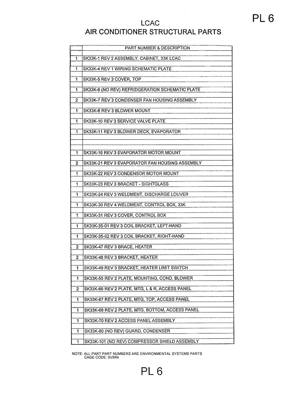
275
COMMERCIAL TECHNICAL MANUAL WITH PERFORMANCE DATA OPERATOR S, UNIT, DIRECT SUPPORT, AND GENERAL SUPPORT MAINTENANCE MANUAL FOR
 TM 24-4120-14&P COMMERCIAL TECHNICAL MANUAL WITH PERFORMANCE DATA OPERATOR S, UNIT, DIRECT SUPPORT, AND GENERAL SUPPORT MAINTENANCE MANUAL FOR AIR CONDITIONER, HORIZONTAL COMPACT, 24,000 BTU/HR 208 VOLT,
WineZone Ceiling Mount Ductless Split 15
 WineZone Ceiling Mount Ductless Split 15 Requires an HVAC technician to install and charge with R-22 refrigerant. Easy to install. Unit plugs into wall outlet. Industrial grade unit for longer life. Indoor
Room Air Conditioner Service and Parts Manual
 Cool Dry Temp Mode Room Air Conditioner Service and Parts Manual F Fan Speed hr Timer 0n 0ff Money Saver Fan Only Auto Swing Power CP06 CP08 93011401_01 CONTENTS 1. PREFACE 1.1 SAFETY PRECAUTIONS...2 1.2
Some of these procedures need to be performed to conform to requirements of the Clean Air Act.
 Leak Detection, Recovery, Evacuation and Charging Four basic service procedures used to repair and maintain a mechanical refrigeration system are leak detection, evacuation, recovery, and refrigerant charging.
Condensing Unit Installation and Operating Instructions
 Bulletin WCU_O&I 01 June 2003 Condensing Unit Installation and Operating Instructions WCU Air Cooled Condensing Unit Table of Contents Section 1. Section 2. Section 3. Section 4. Section 5. Section 6.
ENSPECO Recovery/ Recycle/ Evacuate/ Recharge
 ENSPECO Recovery/ Recycle/ Evacuate/ Recharge RMS 3012 RMS 3034 Approved by UL/SAE to J-1991 R12 Purity Standards Approved by UL/SAE to J-2210 R134 Purity Standards This semi-automatic machine will recover
WMHP Series R410a Heat Pump INSTALLATION INSTRUCTIONS
 WMHP Series R410a Heat Pump INSTALLATION INSTRUCTIONS **WARNING TO INSTALLER, SERVICE PERSONNEL AND OWNER** Altering the product or replacing parts with non authorized factory parts voids all warranty
Calhoon MEBA Engineering School. Study Guide for Proficiency Testing Refrigeration
 Calhoon MEBA Engineering School Study Guide for Proficiency Testing Refrigeration 1. To prevent an injury when working with refrigerants, what safety precautions are necessary? 2. When halogens are in
Air Conditioning Operation and Troubleshooting Matt Dunham
 Air Conditioning Operation and Troubleshooting Matt Dunham Major Components (10 Minutes) Compressor heart of the system, causes refrigerant to flow by increasing the pressure of the refrigerant Metering
KITS COMMON TO HEATING AND COOLING EQUIPMENT 504,652M 03/04. Supersedes 503,249M
 2004 Lennox Industries Inc. Dallas, Texas KITS COMMON TO HEATING AND COOLING EQUIPMENT 504,652M 03/04 Supersedes 503,249M Litho U.S.A. COMPRESSOR REPLACEMENT KIT INSTALLATION INSTRUCTIONS FOR COMPRESSOR
TECHNICAL MANUAL OPERATOR S, UNIT, DIRECT SUPPORT, AND GENERAL SUPPORT MAINTENANCE MANUAL FOR
 TM 9-4120-430-14 TECHNICAL MANUAL OPERATOR S, UNIT, DIRECT SUPPORT, AND GENERAL SUPPORT MAINTENANCE MANUAL FOR AIR CONDITIONER, HORIZONTAL COMPACT, 18,000 BTU/HR 230 VOLT, 1 PHASE, 50/60 HERTZ, ENVIRONMENTAL
OPERATING INSTRUCTIONS 2-1 OPERATOR PREVENTIVE MAINTENANCE CHECKS AND SERVICES (PMCS) 2-5 OPERATOR TROUBLESHOOTING 3-1
 2-5 OPERATOR TROUBLESHOOTING 3-1") TECHNICAL MANUAL TM 9-4120-402-14 OPERATOR'S, UNIT, DIRECT SUPPORT, AND GENERAL SUPPORT MAINTENANCE MANUAL OPERATING INSTRUCTIONS 2-1 OPERATOR PREVENTIVE MAINTENANCE CHECKS AND SERVICES (PMCS) 2-5 OPERATOR
TECHNICAL MANUAL TM 9-4120-402-14 OPERATOR'S, UNIT, DIRECT SUPPORT, AND GENERAL SUPPORT MAINTENANCE MANUAL OPERATING INSTRUCTIONS 2-1 OPERATOR PREVENTIVE MAINTENANCE CHECKS AND SERVICES (PMCS) 2-5 OPERATOR
INSTALLATION INSTRUCTIONS
 ,t_2007 Lennox Industries Inc. Dallas, Texas, USA INSTALLATION INSTRUCTIONS CH33 Series Units EVAPORATOR 505,264M (65484504) 10/07 Supersedes 09/06 COILS n _putech blications ical Litho U.S.A. RETAIN THESE
INSTALLATION, OPERATION, SERVICE & PARTS SUPPLEMENT for
 T-333 Manual INSTALLATION, OPERATION, SERVICE & PARTS SUPPLEMENT for Rooftop Energy Storage Systems (ESS) AIR COOLING UNIT 77-62186-00 THRU -04 & 77-62203-00 T-333 REV. 03/2012 2012 Mobile Climate Control
347002K/177002K/34900
 Service Manual Models: 347002K/177002K 34900/347012K Manifold Block Style Recovery/Recycling/Recharging Unit For R-12 or R-134a Only TABLE OF CONTENTS: Theory of Operation and Safety Precautions... 2 Depressurizing
Condensing Unit Installation and Operating Instructions
 Bulletin ACU_O&I 02 August 2016 Condensing Unit Installation and Operating Instructions ACU Air Cooled Condensers Table of Contents Section 1. General Information... 2 Section 2. Refrigeration Piping...
OPERATIONS AND MAINTENANCE MANUAL FOR THE 8-TON TURF CART ENVIRONMENTAL CONTROL UNIT (ECU) PART NUMBER
 PART NUMBER") OPERATIONS AND MAINTENANCE MANUAL FOR THE 8-TON TURF CART ENVIRONMENTAL CONTROL UNIT (ECU) PART NUMBER 2001927 Prepared by: 860 Douglas Way PO Box 530 Natural Bridge Station, VA 24579 1 1.0 SCOPE: This
OPERATIONS AND MAINTENANCE MANUAL FOR THE 8-TON TURF CART ENVIRONMENTAL CONTROL UNIT (ECU) PART NUMBER 2001927 Prepared by: 860 Douglas Way PO Box 530 Natural Bridge Station, VA 24579 1 1.0 SCOPE: This
Refrigerant Recovery Machine. Model No Operating Manual
 Refrigerant Recovery Machine Model No. 25700 Operating Manual Safety Precautions WARNING : TO PREVENT PERSONAL INJURY AND / OR EQUIPMENT DAMAGE, CAUTION - Risk of injury. This equipment should only be
CME1056 Service Parts. Table of Contents
 This is the parts list for the CME0 ice machine. The CME0 was manufactured in A, D, E and F series, as well as single phase 0 Hz, single phase 0 Hz, and three phase. The E series change was to side panels
ENVIRONMENTAL CONTROL UNIT (ECU) PART NUMBER OPERATIONS AND MAINTENANCE MANUAL
 PART NUMBER OPERATIONS AND MAINTENANCE MANUAL") ENVIRONMENTAL CONTROL UNIT (ECU) PART NUMBER 2001829 OPERATIONS AND MAINTENANCE MANUAL Prepared by: 860 Douglas Way PO Box 530 Natural Bridge Station, VA 24579 1.0 SCOPE: This Operations and Maintenance
ENVIRONMENTAL CONTROL UNIT (ECU) PART NUMBER 2001829 OPERATIONS AND MAINTENANCE MANUAL Prepared by: 860 Douglas Way PO Box 530 Natural Bridge Station, VA 24579 1.0 SCOPE: This Operations and Maintenance
DLCLRA. INSTALLATION INSTRUCTIONS Outdoor Unit Single Zone Ductless System Sizes 36 to 58 TABLE OF CONTENTS
 DLCLRA INSTALLATION INSTRUCTIONS Outdoor Unit Single Zone Ductless System Sizes 36 to 58 Fig. 1 - Size 36 TABLE OF CONTENTS PAGE SAFETY CONSIDERATIONS... 2 PARTS LIST... 3 SYSTEM REQUIREMENTS... 4 WIRING...
38LB/38LF AIR COOLED CONDENSING UNIT
 WORLD LEADER IN AIR CONDITIONING AND HEATING TECHNOLOGY INSTALLATION, START-UP AND SERVICE INSTRUCTIONS 38LB/38LF AIR COOLED CONDENSING UNIT CONTENTS PAGE PHYSICAL DATA 2 PHYSICAL DATA 2 DIMENSION DATA
INSTALLATION INSTRUCTIONS TXV Horizontal Slab Coils WLSH
 TXV Horizontal Slab Coils WLSH These instructions must be read and understood completely before attempting installation. It is important that the Blower and Duct System be properly sized to allow the system
Isco 3700ZR Sampler. Manual Set
 Isco 3700ZR Sampler Manual Set Assembly #60-2744-045 Copyright 2001. All rights reserved, Teledyne Isco Revision D, December 14, 2012 This set of manuals supports the Isco 3700ZR Refrigerated Sampler.
38GHP AIR-COOLED MULTI SPLIT CONDENSING UNITS
 Concepcion Carrier Air conditioning Company Philippines INSTALLATION MANUAL, START-UP & SERVICE INSTRUCTIONS 38GHP AIR-COOLED MULTI SPLIT CONDENSING UNITS CONTENTS: Physical Data and Dimensions........
SERVICE BULLETIN A
 1. PLANNING INFORMATION A. Effectivity: Dassault Falcon 10 aircraft which have installed R-134a Upgrade Kit SZ59K-R134 before August 8, 2002. B. Reason: Upgrade kits before August 8, 2002 did not include
CME650 SERVICE PARTS
 This section contains the parts illustrations and parts lists for the CME650. CM650 ice machines are manufactured in both 60 cycle and 50 cycle. When ordering electrical parts, be certain to match the
Refrigerant Recovery Unit, Model RRU134
 Installation, Operation & Maintenance Manual IOMM RRU134 Group: Refrigerant Effective: December 2000 Supersedes: New Refrigerant Recovery Unit, Model RRU134 1999 McQuay International Table of Contents
CS/CD/CP AIR COOLED CONDENSING UNITS (P/N E207120C R2)
") CS*/CD*/CP* Series Air Cooled Condensing Units Operating and Installation Manual CS/CD/CP AIR COOLED CONDENSING UNITS (P/N E207120C R2) TABLE OF CONTENTS I. Receipt of Equipment 2 II. Piping...4 III. System
CS*/CD*/CP* Series Air Cooled Condensing Units Operating and Installation Manual CS/CD/CP AIR COOLED CONDENSING UNITS (P/N E207120C R2) TABLE OF CONTENTS I. Receipt of Equipment 2 II. Piping...4 III. System
UHIR Series. Horizontal or Vertical Mounting Industrial / Commercial Electric Unit Heater. Owner s Manual
 UHIR Series Horizontal or Vertical Mounting Industrial / Commercial Electric Unit Heater Owner s Manual This manual covers installation, maintenance and repair parts. Read carefully before attempting to
INSTALLATION INSTRUCTIONS
 INSTALLATION INSTRUCTIONS Series Units RETAIN THESE INSTRUCTIONS FOR FUTURE REFERENCE WARNING Improper installation, adjustment, alteration, service or maintenance can cause personal injury, loss of life,
TECHNICAL GUIDE DESCRIPTION SPLIT-SYSTEM AIR-COOLED CONDENSING UNITS MODELS: HF-07 FEATURES B-0703
 TECHNICAL GUIDE SPLIT-SYSTEM AIR-COOLED CONDENSING UNITS MODELS: HF-07 DESCRIPTION These Sunline 2000 units are completely assembled, piped and wired at the factory to provide one-piece shipment and rigging.
INSTALLATION INSTRUCTIONS
 2008 Lennox Industries Inc. Dallas, Texas, USA INSTALLATION INSTRUCTIONS CH33 Series Units EVAPORATOR COILS 505,264M (65484504) 05/08 Supersedes 10/07 Litho U.S.A. RETAIN THESE INSTRUCTIONS FOR FUTURE
OPERATING MANUAL MODEL AIR 1500TM AIR DRYER
 OPERATING MANUAL MODEL AIR 500TM AIR DRYER Puregas, LLC 226-A Commerce St. Tel: 800-52-535 Broomfield, Colorado Fax: 303-657-2205 P/N P0255 REV A, 02/9/4 TABLE OF CONTENTS.0 GENERAL... 3 2.0 SPECIFICATIONS...
INSTALLATION INSTRUCTIONS TXV Horizontal Duct Coils EHD
 TXV Horizontal Duct s EHD These instructions must be read and understood completely before attempting installation. It is important that the Blower and Duct System be properly sized to allow the system
Installation Instructions
 24AHA4 Performance Series Air Conditioner with Puron Refrigerant 1-1/2 to 5 Nominal Tons Installation Instructions Fig. 1-24AHA4 A07532 SAFETY CONSIDERATIONS Improper installation, adjustment, alteration,
INSTALLATION INSTRUCTIONS
 INSTALLATION INSTRUCTIONS SPLIT AIR CONDITIONER OUTDOOR SECTION Models: HAC481-B HAC602-B For Use With: Matching Indoor Blower Coil Units and Matching Add On Coil Units Only Bard Manufacturing Company,
TRI-PLATE B INSTALLATION, OPERATION, AND MAINTENANCE INSTRUCTIONS PART NO EFFECTIVE MARCH 1, 1983 REPRINT APRIL 16, 1999
 TRI-PLATE B INSTALLATION, OPERATION, AND MAINTENANCE INSTRUCTIONS PART NO. 8801469 EFFECTIVE MARCH 1, 1983 REPRINT APRIL 16, 1999 THE MILK COOLING SYSTEMS SPECIALISTS TM FRE-HEATER Part No. 8801469 Table
power Describe the purpose of lockout/tag-out devices Demonstrate use of lockout/tagout
 c. All contestants are required to remain in the contest area until the contest has been torn down and excused by the Chairperson. Note: Your contest may also require a hard copy of your résumé as part
Cased Aluminum Coils "Dedicated Upflow / Downflow" Convertible to horizontal with separately purchased kit
 18-AD32D1-3 Cased Aluminum Coils "Dedicated Upflow / Downflow" Convertible to horizontal with separately purchased kit Upflow models: 4PXCAU24BS3HAA 4PXCBU24BS3HAA 4PXCBU30BS3HAA 4PXCCU30BS3HAA 4PXCBU36BS3HAA
SEA FROST BAITFREEZER 110-VOLT AIR-WATER Twin Valve
 372 ROUTE 4 BARRINGTON, NH 03825 USA TEL (603) 868-5720 FAX (603) 868-1040 1-800-435-6708 E-Mail:sales@seafrost.com www.seafrost.com SEA FROST BAITFREEZER 110-VOLT AIR-WATER Twin Valve Operation and Installation
SERVICE MANUAL FOR MODEL RM-49
 SERVICE MANUAL FOR MODEL RM-49 REQUIRED TOOLS CORDLESS DRILL DRIVE CUTTING TUBING OPEN WRENCH OF 1/2 RATCHET WITH SOCKET OF 7/16 SCREWDRIVER SET WITH SOCKET OF 9/32 VISE GRIP PIERCING VALVE WATCHER SLOTTED
SECTION 7 AIR CONDITIONING (COOLING) UNIT 41 TROUBLESHOOTING
 UNIT 41 TROUBLESHOOTING") SECTION 7 AIR CONDITIONING (COOLING) UNIT 41 TROUBLESHOOTING UNIT OBJECTIVES After studying this unit, the reader should be able to Select the correct instruments for checking an air conditioning unit
SECTION 7 AIR CONDITIONING (COOLING) UNIT 41 TROUBLESHOOTING UNIT OBJECTIVES After studying this unit, the reader should be able to Select the correct instruments for checking an air conditioning unit
TECHNICAL MANUAL CX(E) SPLIT SYSTEMS. Tel: Fax:
 SPLIT SYSTEMS. Tel: Fax:") TECHNICAL MANUAL CX(E) SPLIT SYSTEMS CONTENTS INDEX PART NUMBERS, OPTIONS, UNIT COMBINATIONS, DIMENSIONS & WEIGHTS 3 PERFORMANCE DATA & AIR FLOW 4 SOUND POWER AND SOUND PRESSURE LEVELS 5 ELECTRICAL DATA
TECHNICAL MANUAL CX(E) SPLIT SYSTEMS CONTENTS INDEX PART NUMBERS, OPTIONS, UNIT COMBINATIONS, DIMENSIONS & WEIGHTS 3 PERFORMANCE DATA & AIR FLOW 4 SOUND POWER AND SOUND PRESSURE LEVELS 5 ELECTRICAL DATA
Room Air Conditioner CP06 & CP08. Chill 115 Volts. Service & Parts Manual THE EXPERTS IN ROOM AIR CONDITIONING _02
 Room Air Conditioner Service & Parts Manual 2014-2015 CP06 & CP08 Chill 115 Volts THE EXPERTS IN ROOM AIR CONDITIONING 93011401_02 CONTENTS 1. PREFACE 1.1 SAFETY PRECAUTIONS...2 1.2 INSULATION RESISTANCE
SERVICE MANUAL FOR MODEL RM-26
 SERVICE MANUAL FOR MODEL RM-26 REQUIRED TOOLS CORDLESS DRILL DRIVE CUTTING TUBING OPEN WRENCH OF 1/2 RATCHET WITH SOCKET OF 7/16 SCREWDRIVER SET WITH SOCKET OF 9/32 VISE GRIP PIERCING VALVE WATCHER SLOTTED
CIRRUS AIRPLANE MAINTENANCE MANUAL
 COOLING 1. DESCRIPTION On aircraft serials 183 and subsequent, an optional air condition system is available. This section contains the maintenance practices pertinent to this system. Cabin ventilation
A/C-HEATER SYSTEM - MANUAL
 A/C-HEATER SYSTEM - MANUAL 1986 Isuzu Trooper II 1986 A/C-HEATER SYSTEM Isuzu A/C-Heater Systems - Manual P UP, Trooper II * PLEASE READ THIS FIRST * CAUTION: When discharging air conditioning system,
MINI SLIMLINE COOL VUY-A VUY-A
 an ISO 900:2008 Registered Company MINI SLIMLINE COOL 030-VUY-A 040-VUY-A 8865 GOLL ST. - SAN ANTONIO, TX. - 78266 ph.20-654-77 - fax 20-654-33 900302 REV D 0/28/4, MINI SLIMLINE COOL PG OF Table of Contents
INSTALLATION AND OPERATING INSTRUCTIONS
 INSTALLATION AND OPERATING INSTRUCTIONS HIGH-EFFICIENCY CONDENSING UNITS RAWD- 6 1 2 & 7 1 2 TON RAWE - 6 1 2 & 7 1 2 TON! RECOGNIZE THIS SYMBOL AS AN INDICATION OF IMPORTANT SAFETY INFORMATION!! WARNING
an ISO 9001:2008 Registered Company GOLL ST. - SAN ANTONIO, TX ph fax MINI SPACE SAVER HEAT /COOL
 an ISO 9001:2008 Registered Company 18865 GOLL ST. - SAN ANTONIO, TX. - 78266 - ph.210-654-7171 - fax 210-654-3113 MINI SPACE SAVER HEAT /COOL 01000-QUX-A 01000-VUX-A 900101-VUX-A REV C 3/5/14, MINI SPACE
PROAIR Air Conditioner. CR23 Model INSTRUCTION MANUAL nvent Rev. D P/N
 PROAIR Air Conditioner CR23 Model INSTRUCTION MANUAL Rev. D P/N 89112522 TABLE OF CONTENTS Warranty and Return Policy...2 RECEIVING THE AIR CONDITIONER...3 HANDLING AND TESTING THE AIR CONDITIONER...3
MODEL MW200 MODEL MW600 AIR DRYER
 OPERATING MANUAL MODEL MW200 MODEL MW600 AIR DRYER Mail Address: 226A Commerce St. Tel: 303-465-3063 Broomfield, CO 80020 Fax: 303-465-9294 TABLE OF CONTENTS 1.0 GENERAL...3 2.0 SPECIFICATIONS...3 3.0
Installation Instructions
 38MHR Outdoor Unit Single Zone Ductless System Sizes 09 to 24 Installation Instructions NOTE: Read the entire instruction manual before starting the installation. NOTE: Images are for illustration purposes
Vehicle Level Heating and Air Conditioning Description and Operation A/C System - Manual. A/C System - Manual
 1 of 5 4/7/2008 8:32 AM Home Account Contact ALLDATA Log Out Help Select Vehicle New TSBs Technician's Reference Component Search: METRO TOYOTA OK 1999 Ford Truck F 450 2WD Super Duty V10-6.8L VIN S Vehicle
Homestyle Stacked Washer/ Dryer
 Homestyle Stacked Washer/ Dryer Parts Refer to Page 3 for Model Numbers SWD441C_801998 www.alliancelaundry.com Part No. 801998R6 January 2018 Table of Contents Title Page Parts Ordering Information...
G Series. G Series Air Coils Installation ti Manual ENCASED/UNCASED AIR COILS. Geothermal/Water Source Heat Pumps R-410A Refrigerant 2-5 Ton
 G Series ENCASED/UNCASED AIR COILS Geothermal/Water Source Heat Pumps R-410A Refrigerant 2- Ton Dimensional Data G Series Air Coils Installation ti Manual Installation Information Maintenance IM1018AG1
INSTALLATION MANUAL LIST OF SECTIONS LIST OF FIGURES LIST OF TABLES SECTION I: SAFETY UIM-C-0214
 INSTALLATION MANUAL FULL-CASED MULTI-POSITION FOR COOLING/HEAT PUMPS MODELS: MC FULL-CASED UPFLOW/COUNTERFLOW FOR COOLING/HEAT PUMPS MODELS: FC PARTIAL-CASED UPFLOW FOR COOLING/HEAT PUMP MODELS: PC ISO
Reach-In Refrigerators and Freezers Service Manual
 Reach-In Refrigerators and Freezers Service Manual Part No. 80-0899-3 Rev. A 11/96 Safety Notices As you work on the Reach-In, be sure to pay close attention to the safety notices in this manual. Disregarding
SERVICE PARTS/OPERATION for
 T--357 Manual SERVICE PARTS/OPERATION for MCC Heater Units 12-XXXX Series T -357 REV. 05/2015 2012 Mobile Climate Control Table of Contents SAFETY SUMMARY... Safety-1 UNIT SPECIFICATIONS... Spec-1 MAINTENANCE...
GENERAL 2004 HVAC SYSTEMS. Manual HVAC System - Sorento SPECIFICATIONS. Fig. 1: Air Conditioner Specifications Courtesy of KIA MOTORS AMERICA, INC.
 Fig. 2: Blower & Evaporator Unit Specifications 2004 HVAC SYSTEMS Manual HVAC System - Sorento GENERAL SPECIFICATIONS AIR CONDITIONER Fig. 1: Air Conditioner Specifications BLOWER AND EVAPORATOR UNIT HEATER
SERVICE MANUAL FOR MODEL RM-10
 SERVICE MANUAL FOR MODEL RM-10 REQUIRED TOOLS CORDLESS DRILL COPPER CUTTING TUBE 1/2 OPEN WRENCH SOLDERING IRON SCREWDRIVER SET WITH 9/32 SOCKET VISE GRIP PIERCING VALVE PRECISION FLAT BLADE SLOTTED SCREWDRIVER
1998 Expedition/Navigator Workshop Manual
 Page 1 of 8 SECTION 412-00: Climate Control System - General Information 1998 Expedition/Navigator Workshop Manual DESCRIPTION AND OPERATION Procedure revision date: 02/11/2000 Climate Control System WARNING:
DLCSRA. INSTALLATION INSTRUCTIONS Outdoor Unit Ductless Split System Sizes 09 to 36 TABLE OF CONTENTS
 DLCSRA INSTALLATION INSTRUCTIONS Outdoor Unit Ductless Split System Sizes 09 to 36 NOTES: Read the entire instruction manual before starting the installation. Images are for illustration purposes only.
INSTALLATION INSTRUCTIONS TXV Coils for Manufactured Housing EMA
 TXV Coils for Manufactured Housing EMA NOTE: Read the entire instruction manual before starting the installation. SAFETY CONSIDERATIONS Improper installation, adjustment, alteration, service, maintenance,
INSTALLATION MANUAL UN-CASED A COILS UPFLOW FOR COOLING/HEAT PUMPS FLEX COILS FOR FIELD INSTALLED TXV MODELS: UC LIST OF SECTIONS LIST OF FIGURES
 INSTALLATION MANUAL UN-CASED A COILS UPFLOW FOR COOLING/HEAT PUMPS FLEX COILS FOR FIELD INSTALLED TXV MODELS: UC ISO 9001 Certified Quality Management System SAFETY................................................
Truck Edition V-220 / V-320 Series Single Temperature Systems TK IM (Rev. 0, 06/17)
") Installation Manual Truck Edition V-220 / V-320 Series Single Temperature Systems TK 56321-18-IM (Rev. 0, 06/17) Installation Manual Truck Edition V-220 / V-320 Series Single Temperature Systems TK 56321-18-IM
Installation Manual Truck Edition V-220 / V-320 Series Single Temperature Systems TK 56321-18-IM (Rev. 0, 06/17) Installation Manual Truck Edition V-220 / V-320 Series Single Temperature Systems TK 56321-18-IM
INSTALLER'S GUIDE. ALL phases of this installation must comply with NATIONAL, STATE AND LOCAL CODES
 11-AC11D2-5 INSTALLER'S GUIDE ALL phases of this installation must comply with NATIONAL, STATE AND LOCAL CODES Models: Condensing Units 2A7A5024-048, 2A7A4018-060, 2A7A2018-060 & 2A7A1018-060 IMPORTANT
PROAIR Air Conditioner. CR29 Model INSTRUCTION MANUAL nvent Rev. I P/N
 PROAIR Air Conditioner CR29 Model INSTRUCTION MANUAL Rev. I P/N 89104461 TABLE OF CONTENTS Warranty and Return Policy...2 RECEIVING THE AIR CONDITIONER...3 HANDLING AND TESTING THE AIR CONDITIONER...3
INSTALLATION INSTRUCTIONS
 INSTALLATION INSTRUCTIONS T CLASS TSA Series 6 to 20 Ton AIR CONDITIONERS 6 20 TONS 506147 01 06/11 Supersedes 3/11 Litho U.S.A. RETAIN THESE INSTRUCTIONS FOR FUTURE REFERENCE IMPORTANT The Clean Air Act
Installation Instructions
 40MBFQ Floor Console Ductless System Sizes 09 to 12 Installation Instructions TABLE OF CONTENTS PAGE SAFETY CONSIDERATIONS... 2 PARTS LIST... 3 SYSTEM REQUIREMENTS... 4 DIMENSIONS... 5 CLEARANCES... 5
Installation Instructions
 38MPRA Outdoor Unit Single Zone Ductless System Sizes 09 to 12 Installation Instructions NOTES: Read the entire instruction manual before starting the installation. Images are for illustration purposes
INSTALLATION MANUAL LIST OF SECTIONS LIST OF FIGURES LIST OF TABLES SECTION I: SAFETY
 INSTALLATION MANUAL FULL-CASED MULTI-POSITION FOR COOLING/HEAT PUMPS MODELS: MC FULL-CASED UPFLOW/COUNTERFLOW FOR COOLING/HEAT PUMPS MODELS: FC PARTIAL-CASED UPFLOW FOR COOLING/HEAT PUMP MODELS: PC ISO
Installation Instructions
 PREFERREDT SERIES AIR CONDITIONER WITH PURONR REFRIGERANT 1-1/2 TO 5 NOMINAL TONS Installation Instructions Fig. 1 --- 538A NOTE: Read the entire instruction manual before starting the installation. TABLE
HEATING AND VENTILATION
 SECTION 14-102.04 14-102.04/ 1 2007OC19 DESCRIPTION The heating, ventilation and air conditioning (HVAC) system is designed to optimize passenger comfort. The system regulates interior vehicle atmosphere,
T-SERIES Air Conditioner. T43 Model INSTRUCTION MANUAL nvent Rev. I P/N
 T-SERIES Air Conditioner T43 Model INSTRUCTION MANUAL Rev. I P/N 10-1008-145 TABLE OF CONTENTS Warranty and Return Policy...2 IMPORTANT NOTICE...2 RECEIVING THE AIR CONDITIONER...3 HANDLING AND TESTING
R Series Cooling Modules
 TM Small Duct High Velocity Heating, Cooling and Indoor Air Quality Systems R Series Cooling Modules Models RCM-50 RCM-70 RM-100 Manufactured By Module-RCM/RM-Series-Installation-Manual-120113 Refrigerant
T-SERIES Air Conditioner. T29 Model INSTRUCTION MANUAL nvent Rev. I P/N
 T-SERIES Air Conditioner T29 Model INSTRUCTION MANUAL Rev. I P/N 89104464 TABLE OF CONTENTS Warranty and Return Policy...2 IMPORTANT NOTICE...2 RECEIVING THE AIR CONDITIONER...3 HANDLING AND TESTING THE
R Series Cooling Modules
 R Series Cooling Modules Models RCM/RPM 50 RCM 70 RM 100 RM 140 Manufactured By Energy Saving Products Ltd. Standard ESP 105.03 Refrigerant Modules (RCM/RM) Fig. 02 - Mounting brackets The cooling coil
DEPARTMENT OF THE ARMY TECHNICAL MANUAL (FSN ) This copy is a reprint which includes current pages from Changes 1 through 3.
 This copy is a reprint which includes current pages from Changes 1 through 3.") TM 5-4120-239-14 DEPARTMENT OF THE ARMY TECHNICAL MANUAL TECHNICAL MANUAL OPERATOR, ORGANIZATIONAL, DIRECT SUPPORT AND GENERAL SUPPORT MAINTENANCE MANUAL AIR CONDITIONER, HORIZONTAL COMPACT, 9,000 BTU
TM 5-4120-239-14 DEPARTMENT OF THE ARMY TECHNICAL MANUAL TECHNICAL MANUAL OPERATOR, ORGANIZATIONAL, DIRECT SUPPORT AND GENERAL SUPPORT MAINTENANCE MANUAL AIR CONDITIONER, HORIZONTAL COMPACT, 9,000 BTU
Glass Door Merchandiser. Model RM-49
 Glass Door Merchandiser Model Number: Issued: 02-22-2017 Revised: 02-22-2017 2 TABLE OF CONTENTS UNIT FEATURES 4 Page CROSS SECTION VIEWS 5 EXPLODED VIEW 6, 7 REFRIGERATION SYSTEM 8, 9 CONDENSING UNIT
National Comfort Products 539 Dunksferry Road Bensalem, PA (215) Fax: (215)
 Fax: (215)") National Comfort Products 539 Dunksferry Road Bensalem, PA 19020 (215) 244-1400 1-800-523-7138 Fax: (215) 244-9579 R410a SPLIT-SYSTEM CONDENSING UNIT INSTALLATION INSTRUCTIONS 1000 3000 4000 SERIES 1.
National Comfort Products 539 Dunksferry Road Bensalem, PA 19020 (215) 244-1400 1-800-523-7138 Fax: (215) 244-9579 R410a SPLIT-SYSTEM CONDENSING UNIT INSTALLATION INSTRUCTIONS 1000 3000 4000 SERIES 1.
OPERATION AND SERVICE for
 T-313 Manual OPERATION AND SERVICE for 68RM50-100/101 MICROMAX T-313 REV. 07/2012 2012 Mobile Climate Control SAFETY SUMMARY GENERAL SAFETY NOTICES The following general safety notices supplement the specific
GCG-10. Instruction Manual. G-Series Cooler. Manual is for the following models: GCG-10-N33EB G-10-N33EB UPRIGHT COOLER
 G-Series Cooler GCG-10 UPRIGHT COOLER Manual is for the following models: GCG-10-N33EB G-10-N33EB Instruction Manual Manual is for the following models: GCG-10-N33EB G-10-N33EB Instruction Manual GCG-10
SERVICING PROCEDURE R-410A LEAK TEST EVACUATION CHARGING. Bard Manufacturing Company, Inc. Bryan, Ohio Manual Page 1 of 11
 SERVICING PROCEDURE R-410A LEAK TEST EVACUATION CHARGING Bard Manufacturing Company, Inc. Bryan, Ohio 43506 Since 1914...Moving ahead, just as planned. Manual No.: 2100-479 Supersedes: NEW File: Volume
TM NOVEMBER 1986 HEATER, SPACE, MULTIFUEL WITH BLOWER, 60,000 BTU/HR, 120 V UH-68G ( )
") OPERATOR S, UNIT, AND INTERMEDIATE MAINTENANCE MANUAL TABLE OF CONTENTS i OPERATING INSTRUCTIONS 2-1 UNIT MAINTENANCE INSTRUCTIONS 3-1 INTERMEDIATE MAINTENANCE INSTRUCTIONS 4-1 MAINTENANCE ALLOCATION CHART
OPERATOR S, UNIT, AND INTERMEDIATE MAINTENANCE MANUAL TABLE OF CONTENTS i OPERATING INSTRUCTIONS 2-1 UNIT MAINTENANCE INSTRUCTIONS 3-1 INTERMEDIATE MAINTENANCE INSTRUCTIONS 4-1 MAINTENANCE ALLOCATION CHART
SERVICE PARTS for ECO353N
 T-60PL Manual SERVICE PARTS for ECO5N Models Y50-50 & Y50-50 T-60PL REV. 0/0 0 Mobile Climate Control TABLE Of CONTENTS INTRODUCTION... i CONFIGURATION IDENTIFICATION... i OPTION DESCRIPTION... i ORDERING
User s Information and Installation Instructions
 Outdoor Air Conditioner User s Information and Installation Instructions 2-Stage R-410A Split System These units have been designed and tested for capacity & efficiency in accordance with A.H.R.I. Standards.
TSA WARNING. Service Literature TSA SERIES UNITS. 6, 7.5, 10, 12.5, 15 & 20 ton
 Service Literature Corp. 0903 L1 Revised: March 2011 TSA SERIES UNITS TSA 6, 7.5, 10, 12.5, 15 & 20 ton The TSA units are designed for light commercial applications, with a remotely located blower coil
Installation Owner Diagnostics
 Installation Owner Diagnostics Split System Cooling Condensers Model CTA 7 1/2 to 15 Tons Models A and later Design Sequence CTA 090A***A 60 HZ 120A***A 60 HZ 120B***A 60 HZ 180B***A 60 HZ SS-SVN11A-EN
Home Stacked Washer/Dryer
 Home Stacked Washer/Dryer Refer to Page 3 for Model Numbers Parts SWD443C_802107 www.comlaundry.com Part No. 802107R6 August 2014 Table of Contents Title Page Parts Ordering Information... 2 Serial Plate
PROAIR Air Conditioner. CR43 Model INSTRUCTION MANUAL nvent Rev. H P/N
 PROAIR Air Conditioner CR43 Model INSTRUCTION MANUAL Rev. H P/N 10-1008-130 TABLE OF CONTENTS Warranty and Return Policy...2 RECEIVING THE AIR CONDITIONER...3 HANDLING AND TESTING THE AIR CONDITIONER...3
OWNER S MANUAL. High-Wall Fan Coil Unit CONTENTS
 OWNER S MANUAL High-Wall Fan Coil Unit Page GENERAL 2,3 OPERATING MODES 2 REMOTE CONTROL 2 OPERATION 3-9 REMOTE CONTROL OPERATION 3 INDOOR UNIT DISPLAY 5 EMERGENCY OPERATION 5 PRESSING THE ON/OFF BUTTON
REF5-BB Undercounter Blood Bank Refrigerator
 REF5-BB Undercounter Blood Bank Refrigerator Order parts online www.follettice.com Installation, Operation and Service Manual Following installation, please forward this manual to the appropriate operations
AIR CONDITIONING. Carrier Corporation 2002 Cat. No
 AIR CONDITIONING Carrier Corporation 2002 Cat. No. 020-016 1. This refresher course covers topics contained in the AIR CONDITIONING specialty section of the North American Technician Excellence (NATE)
Operation Manual SCT14B and SCT18B. Inspection. 3 General Description. 3 General Requirements. 3 Standard Features.
 Spot Cooling Systems, Inc. 120 Century Drive Suite 00 Carrollton, TX 7006 00-6-776 Operation Manual SCT1B and SCT1B Warning! Improper installation, adjustment, alteration, service, or maintenance can cause
INTRODUCTION. Special Applications of Package Air Conditioners. Instant Cooling Requirement in Wedding Ceremonies
 Pakistan s Largest Manufacturers of Air-Conditioners PACKAGE TYPE UNIT FOR MOBILE APPLICATIONS Provides Turnkey Projects Conceptual Planning to Commissioning of HVACR Projects THE LARGEST MANUFACTURER
SEA FROST BD 12 OR 24-VOLT D.C. AIR-COOLED SYSTEM
 148 OLD CONCORD TURNPIKE BARRINGTON, NH 03825 USA TEL (603) 868-5720 FAX (603) 868-1040 1-800-435-6708 E-Mail:sales@seafrost.com www.seafrost.com SEA FROST BD 12 OR 24-VOLT D.C. AIR-COOLED SYSTEM CONDENSING
User s Information and Installation Instructions
 Outdoor Air Conditioner User s Information and Installation Instructions 10 SEER Standard Efficiency Split System These units have been designed and tested for capacity and efficiency in accordance with
National Comfort Products 539 Dunksferry Road Bensalem, PA (215) Fax: (215)
 Fax: (215)") National Comfort Products 539 Dunksferry Road Bensalem, PA 19020 (215) 244-1400 1-800-523-7138 Fax: (215) 244-9579 SPLIT-SYSTEM CONDENSING UNIT INSTALLATION INSTRUCTIONS 1000 3000 4000 SERIES 1. 2. 3.
National Comfort Products 539 Dunksferry Road Bensalem, PA 19020 (215) 244-1400 1-800-523-7138 Fax: (215) 244-9579 SPLIT-SYSTEM CONDENSING UNIT INSTALLATION INSTRUCTIONS 1000 3000 4000 SERIES 1. 2. 3.