INSTALLATION & OWNER S MANUAL
|
|
|
- Emma Page
- 5 years ago
- Views:
Transcription

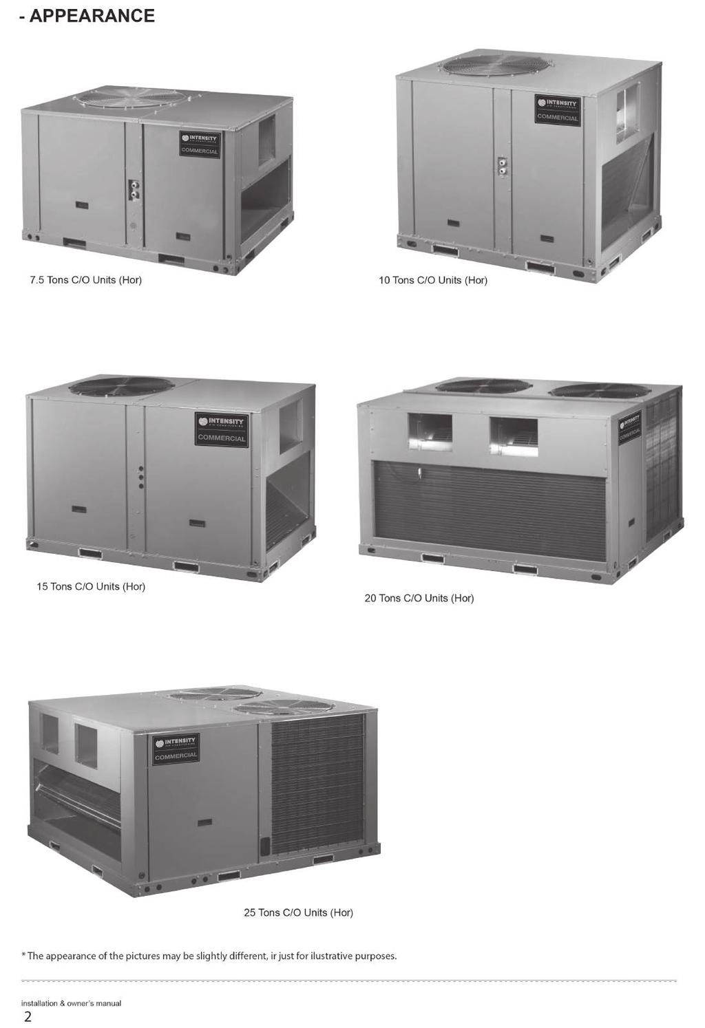
1 ROOFTOP PACKAGE COOLING ONLY 7.5, 0, 5, 20 y 25 Tons. IPCH090KF-5, IPCH20KF-5, IPCH80KF-5, IPCH240KF-5, IPCH300KF-5. INSTALLATION & OWNER S MANUAL intensity.mx MAN-I-IPCH/5-098
2 CONTENTS Thank you very much for purchasing our air conditioner, Before using your air conditioner, please read this manual carefully and keep it for future reference. Nomenclature CODE NAME C/O Cooling Only E/Heater+C Cooling units with Electric Heater Hor.& Dow. Horizontal & Downflow Units (Optional) Hor. Horizontal Units Dow. Downflow Units PAGE ACCESSORIES... GENERAL INFORMATION... APPEARANCE...2 UNIT DIMENSIONS...3 LOCATIONS AND RECOMMENDATIONS...8 INSTALLATION...8 ELECTRICAL WIRING...9 SPECIFICATION...4 START-UP...26 MAINTENANCE ACCESSORIES Tab.- Name of accessories Manual Drain outlet Snap ring Drain pipe Wire controller and wire Qty 2. GENERAL INFORMATION Shape Warnings and Cautions appear at appropriate locations throughout this manual. Read these carefully. WARNING: Indicates a potentially hazardous situation which, if not avoided, could result in death or serious injury. CAUTION: Indicates a potentially hazardous situation which, if not avoided, may result in minor or moderate injury. It may also be used to alarm against unsafe practices and where property-damage-only accidents could occur. CAUTION Read this entire manual before beginning installation procedures. Bodily injury can result from high voltage electrical components, fast moving fans. For protection from these inherent hazards during installation and servicing, the electrical supply must be disconnected. If operating checks must be performed with the unit operating, it is the technicians responsibility to recognize these hazards and proceed safely. WARNING Ask your dealer for installation of the air conditioner. Incomplete installation performed by yourself may result in a water leakage, electric shock, and fire. Ask your dealer for improvement, repair, and maintenance. Incomplete improvement, repair, and maintenance may result in a water leakage, electric shock, and fire. In order to avoid electric shock, fire or injury, or if you detect any abnormality such as smell of fire, turn off the power supply and call your dealer for instructions. Never replace a fuse with that of wrong rated current or other wires when a fuse blows out. Use of wire or copper wire may cause the unit to break down or cause a fire. Do not insert fingers, rods or other objects into the air inlet or outlet. When the fan is rotating at high speed, it will cause injury. Never use a flammable spray such as hair spray, lacquer or paint near the unit. It may cause a fire. Never inspect or service the unit by yourself. Ask a qualified service person to perform this work. Keep far away from high-frequency equipment. Keep away from the following places: A place where it is full of oil, gas; places where salty air surrounding(near the coast); and a place where is caustic gas(the sulfide in hotspring). Location in above places may cause malfunction or shorten the life span of the machine. In the cace of extremely strong wind, please prevent the air from flowing backwards into the outdoor unit. Snow canopy is necessary in sonwfall places on the outdoor unit. Please consult the local dealer for details. In the frequent thunderstruck place, lightning proof actions should be taken. To prevent refrigerant leak, contact your dealer. When the system is installed and runs in a small room, it is required to keep the concentration of the refrigerant, if by any chance coming out, below the limit. Otherwise, oxygen in the room may be affected, resulting in a serious accident. The refrigerant in the air conditioner is safe and normally does not leak. If the refrigerant leaks in the room, contact with a fire of a burner, a heater or a cooker may result in a harmful gas. Turn off any combustible heating devices, ventilate the room, and contact the dealer where you purchased the unit. Do not use the air conditioner until a service person confirms that the portion where the refrigerant leaks is repaired. If the supply cord is damaged, it must be replaced by the manufacturer or its service agent or a similarly qualified person in order to avoid a hazard. The temperature of refrigerant circuit will be high, please keep the interconnection cable away from the copper tube. The appliance should not be used by children without supervision.
3
4 3. UNIT DIMENSIONS Units: mm 7.5 Tons C/O Units ( Hor.) Condenser fan 840 Maintain orifice for air supply motor Fig Fig.3-5 Hole for bottom installation 8-5x Fig.3-6 3
5 0 Tons C/O Units ( Hor.) Units: mm 462 Condenser fan Maintain orifice for air supply motor 05 Fig (C) Tons C/O Units ( Hor.) Fig.3-8 Hole for bottom installation 0-5x Fig.3-9 4
6 5 Tons C/O Units ( Hor.) Units: mm Condenser fan 227 Maintain orifice for air supply motor Fig Fig.3- Hole for bottom installation, 2-5x Fig.3-2 5
7 20 Tons C/O Units ( Hor.) Units: mm Condenser fan Maintain orifice for air supply motor 247 Compressor panel Fig.3-3 Horizontal supply opening Horizontal return opening Control panel Fig.3-4 Hole for bottom installation *Ø *Ø Fig.3-5 Basic model of this product does not have bottom air discharge (downflow). Manufacturer will make bottom discharge available at the request of customer. 6
8 Units: mm 25 Tons C/O Units ( Hor.) Condenser fan 245 Maintain orifice for air supply motor Drain connection hole Hole for wires Fig.3-6 Horizontal supply opening Horizontal return opening Fig.3-7 Hole for bottom installation Fig.3-8 7
9 4. LOCATIONS AND RECOMMENDATIONS 4. Horizontal airflow application These units are designed and certified for outdoor installations. These units may be installed directly on wood flooring or on Class A, Class B, or Class C roof covering material. Location of the unit must allow service clearance around it. Clearance of the unit must be given careful consideration. Check the handling facilities to ensure the safety of personnel and the unit(s). Caution must be taken at all times to avoid Personal injuries and/or damage to equipment. The unit must be mounted level for proper drainage of water through the holes in the base pan. The unit must not be exposed to direct roof water runoff. Flexible duct connectors must be of a flame retardant material. All duct work outside of the structure must be insulated and weatherproofed in accordance with local codes. 5. INSTALLATION 5. Lifting Rigging cables should have adequate capability to resist 3 times weight of unit. Before lift, please check and ensure that hooks are holding tightly to unit and lifting angles are no less than 60.(See Fig. 5-) Cloth material or hard-paper should be padded in the contact place between unit and rigging cable. Rigging cable should be entwined a round at the hook for prevent danger by cable slip because of weight unbalance. During lifting, anyone forbidden lingering under the lifting unit. Spreader bars Holes through exterior walls must be sealed in accordance with local codes. All fabricated outdoor ducts should be as short as possible. 4.2 Clearances The recommended clearances for single-unit installations are illustrated in Fig.4- These minimum requirements are not only an important consideration when determining unit placement, but they are also essential to ensure adequate serviceability, maximum capacity, and peak operating efficiency. Any reduction of the unit clearances indicated in these illustrations may result in condenser coil starvation or the recirculation of warm condenser air. Actual clearances which appear to be inadequate should be reviewed with a local engineer. See the unit's nameplate for the absolute minimum clearance between the unit and any combustible surface(s). Units: mm Rooftop-units For roof top applications using a field fabricated frame and ducts, use the following procedure: The frame must be located and secured by bolting or welding to the roof. Flashing is required. The hole in the roof must be prepared in advance of installing the unit. Secure the ducts to the roof. Place the unit on the frame or roof curb. Fig.5- Secure the unit to the frame or roof curb Overhead air Clearance Insulate any ductwork outside of the structure with at least 2 inches of insulation and then weatherproof. There must be a weatherproof seal where the duct enters the structure. Complete the installation according to the instructions in the following sections of this manual. Typical rooftop application with frame.((see Fig. 5-2) Fig.4- Fig.5-2 8
10 5.3 Ground level-horizontal units For ground level installations, the unit should be positioned on a pad in the size of the unit or larger. The unit must be level on the pad. The pad must not come in contact with the structure. Be sure the outdoor portion of the supply and return air ducts are as short as possible. Proceed with the installation as follows: Place the unit on the pad. X mm 30tons Others 0<X X 40 Attach the supply and return air ducts to the unit. Insulate any ductwork outside of the structure with at least 2 inches of insulation and weatherproof. There must be a weatherproof seal where the duct enters the structure. 5.5 Ductwork Fig.5-4 Complete the installation according to the instructions in the following sections of this manual. Attaching horizontal ductwork to unit Typical ground level application All conditioned air ductwork should be insulated to minimize heating and cooling duct losses. Use a minimum of 2 inches of insulation with a vapor barrier. The outside ductwork must be weatherproofed between the unit and the building. When attaching ductwork to a horizontal unit, provide a flexible watertight connection to prevent noise transmission from the unit to the ducts. The flexible connection must be indoors and made out of heavy canvas. NOTE Do not draw the canvas taut between the solid ducts. Unit 5.4 Condensate drain piping Fig.5-3 Weather proof this seam Field duct Fig ELECTRICAL WIRING WARNING An all-pole disconnection switch having a contact separation of at least 3mm in all poles should be connected in fixed wiring. The appliance shall be installed in accordance with national wiring regulations. Drain connection hole Drain outlet Snap ring Drain pipe An all-pole disconnection device which has at least 3mm separation distance in all pole and a residual current device(rcd)with the rating of above 0mA shall be incorporated in the fixed wiring according to the national rule. The appliance shall be installed in accordance with national wiring regulations. 9
11 6. Protections and safety control Minutes delay for the compressor start-up At the beginning of energizing, 3-minutes delay should be taken to start the compressor. while after the stop of the compressor, 7-minutes delay should be taken to re-start the compressor. Compressor discharge temperature protection When discharge temperature >257 ºF, the compressor will stop. Reverse phase protection relay The reverse phase protection relay will make the unit not start, when the power source is incorrectly connected. The checking of phase order is just carried out at the first time of electrifying. If malfunction happens then the checking will be going on until the order of phase is right, and the E0 will be displayed on the board. If there is no problem in the first checking, then it will be omitted. High pressure and low pressure protection When high pressure 638 Psi, and lower pressure 2Psi, the unit will stop. 6.2 Electrical data Tab.6-220V 3Ph~ 60Hz Compressor Evaporator fan motor Condenser fan motor Nominal ton Model type Type of flow STC RNC IPT Qty RNC IPT Qty RNC (each) IPT (each) Qty 7.5 C/O Hor C/O Hor C/O Hor C/O Hor C/O Hor NOTES STC: Starting Current (A) RNC: Running Current (A) IPT: Input Power (kw) Qty: Quantity These data are based on the following conditions. Evaporator Air Input Temperature 89.6 ºF DB,.4 ºF WB. Condenser Air Input Temperature 25.6 ºF DB. 0
12 Tab Wiring provision Wiring length between room thermostat and unit(one way) Field wiring The units are internally wired at the factory according to generally accepted electrical technology. Minimum wire size(mm2) 0m 5m 20m 30m 40m Required field wiring Main power wiring to the unit control wiring between the control center and the unit, and earth wiring are required in the field. Required components The following components are required: main power fuses, conduit coupling, and field supplied room thermostat. Wire and fuse size selection for main power source Wire and fuse sizes should be selected in accordance with national and standard, taking the designed maximum current shall be the total of the compressor maximum current, condenser fan motor current and evaporator fan motor current(refer to electrical data ). Wire size between room thermostat and unit The wire size between the room thermostat and the unit should be determined according to the following table, because the 24V power source is applied to the control circuit. NOTE Before connecting the device to the public low-voltage supply systems the permission of the electricity supplier is forcefully necessary. 6.4 Operating conditions For proper performance, run the unit under the following temperature conditions: Tab.6-3 Cooling operation Outdoor temperature: 50 F to 25.6 F Room temperature: 62 F to 88 F Caution Room relative humidity less than 80%. If the unit operates in excess of this figure,the surface of the unit may attract condensation. 6.5 Main power supply Tab.6-2 Model type Unit main power Main power switch Fuse Wires for Power supplies Type of wires 7.5Tons C/O 220V 3Ph~ 60Hz 63A 50A 3x6mm 2 3xUL05 5AWG +2x0mm 2 2xUL05 7AWG 0Tons C/O 220V 3Ph~ 60Hz 75A 63A 3x6mm 2 3xUL05 5AWG +2x0mm 2 2xUL05 7AWG 5Tons C/O 220V 3Ph~ 60Hz 00A 90A 3x25mm 2 3xUL05 3AWG +2x0mm 2 2xUL05 7AWG 20Tons C/O 220V 3Ph~ 60Hz 25A 0A 3x35mm 2 3xUL05 2AWG +2x6mm 2 2xUL05 5AWG 25Tons C/O 220V 3Ph~ 60Hz 50A 25A 3x50mm 2 +2x25mm 2 3xUL05 /0AWG 2xUL05 3AWG The power supply designation is H07RN-F. NOTE
13 6.6 Control wiring Power supply Suggestion: Thermostat choose KJR-23B or Non-programmed eletrical thermostat series of Honeywell, such as TH 5220D. Wiring please refer to the Owner s Manual of the thermostat. L L2 L3 N Dial code settings Set the dial code SW3 of PCB in unit s wire control box, After settings, please shut off the power supply and then repower, otherwise, the new settings function couldn t work. Next wire joint also available L L2 L3 N A B C N Fig.6- When SW3 has been set in ON, please select KJR-2B wire controller; When SW3 has been set in, please select KJR-23B wire controller, KJR-23B is optional. For C/O Units 5-25 Tons To connect with wire controller For C/O Units 5-25 Tons Fig.6-2 For E/Heater+C Units KJR- 2B A B C D E 5-terminal Group BROW N RED YELLOW BL ACK WH ITE ON SW3 CN7 MAIN CONTROL BOARD CN9 CN36 WHITE RED YELLOW GREEN R G Y (C) XT2 R G Y (C) R G Y W (C) TO THE WIRE CONTROLLER Fig.6-5 For C/O Units 7.5, 0(C) Tons B Y MAIN CONTROL BOARD G R C BROWN RED GREEN YELLOW BLUE Fig.6-3 KJR- 2B A B C D E 5-terminal Group BROW N RED YELLOW BL ACK WH ITE For E/Heater+C Units ON SW3 CN7 CN9 MAIN CONTROL BOARD CN36 WHITE RED YELLOW BLUE R G Y W (C) GREEN XT2 C R G Y B XT4 TO THE WIRE CONTROLLER 6.7 Error code Tab.6-5 NUM TO THE WIRE CONTROLLER 7.5, 0(C) Tons Fig.6-4 CODE STANDBY FUNCTION PHASE-MISSING PHASE-ERROR T SENSOR FAILURE HIGH PRESSURE PROTECTION VENT PROTECTION T2 SENSOR FAILURE T3 SENSOR FAILURE T4 SENSOR FAILURE LED(RED) LED2(YELLOW) LED3(GREEN) OFF OFF ON ON ON ON FLASH FLASH FLASH FLASH FLASH FLASH FLASH OFF FLASH OFF FLASH FLASH ON FLASH FLASH T2 EVAPORATOR LOW TEMP. PROTECTION T2 EVAPORATOR HIGH TEMP. PROTECTION T3 CONDENSOR HIGH TEMP. PROTECTION LINE CONTROLLER INPUT FAILURE OFF FLASH FLASH FLASH FLASH ON OFF FLASH OFF ON OFF ON 2 COMPRESSOR OVERCURRENT PROTECTION OFF OFF FLASH 3 COMPRESSOR-INHALING LOW PRESSURE PROTECTION FLASH ON FLASH 4 DEFROST ON FLASH FLASH Fig.6-6 2
14 Tab Tons Type Content Code Remarks Normal Standby Normal Constraint cool on Normal Run 0. Error Compressor phase sequence error or phase default E0 Error Outdoor coil sensor in sys. A error E Error Outdoor coil sensor in sys. B error E2 Error Overcurrent protection of system A are active 3 times within one hour E3 Unit shall be power off to recovery Error Overcurrent protection of system B are active 3 times within one hour E4 Unit shall be power off to recovery Error Indoor coil sensor in sys. A error E5 Error Indoor coil sensor in sys. B error E6 Error High low pressure protection or discharge temperature protection of system A reached 3 times E7 Unit shall be power off to recovery Error High low pressure protection or discharge temperature protection of system B reached 3 times E8 Unit shall be power off to recovery Error Indoor sensor error E9 Error Outdoor ambient sensor error EA Error Wire controller output error Eb Error EEPROM error EE Protection Overcurrent protection in sys.a P0 Protection Overcurrent protection in sys.b P Protection Overcurrent protection for indoor fan P2 Protection Comprehensive protection for outdoor fan P3 Protection Protection Protection for Hi./Lo. pressure or exhaust temp. in sys.a Protection for Hi./Lo. pressure or exhaust temp. in sys.b P4 P5 Comprehensive protection in sys.a Comprehensive protection in sys.b Protection Hi-pressure protection initiated in T2 evaporator stops the outdoor unit fan P6 Protection Hi-pressure protection initiated in T2 evaporator stops the outdoor unit fan and compressor P7 Protection Protection for condenser Hi-temp. in sys.a P8 Protection Protection for condenser Hi-temp. in sys.b P9 Protection Anti-freezing protection for evaporator in sys. A Pc Protection Anti-freezing protection for evaporator in sys. B Pd Protection Defrosting df Protection Protection for outdoor temp PA 3
15 7. SPECIFICATION 7. Physical Data Tab.7-220V 3Ph ~ 60Hz Nominal ton 7.5 Tons 0 Tons 5 Tons 20 Tons Model type C/O C/O C/O C/O Type of flow Cooling capacity(net) (Btu/h) (Ⅰ) Capacity Heating capacity (Btu/h) Performance EER Hor Hor Hor. Hor Length(mm) Dimensions Width(mm) Heigth(mm) Net weight(kg) Refrigerant type R40A R40A R40A R40A Flow control Piston Piston Piston Piston Compressor Quantity/Type /Scroll /Scroll 2/Scroll 2/Scroll Rows Outdoor coil Fins per inch Tube diameter(in.) 9/32 9/32 5/6 9/32 Rows Indoor coil Fins per inch Tube diameter(in.) 9/32 9/32 9/32 9/32 Quantity used/diameter(mm) /700 /700 /750 2/750 Type Propeller Propeller Propeller Propeller Outdoor fan Drive type Quantity speeds Quantity motors/power(kw) Direct /.65 Direct /.58 Direct Direct /.64 2/.865*2 Motor RPM Nominal total CFM Quantity used/model /0 0 /2 2 /5 5 /SYD35R2-L Type FC Centrifugal FC Centrifugal FC Centrifugal FC Centrifugal Indoor fan Drive type Quantity speeds Direct 3 Belt Variable sheave Belt Variable sheave Belt Variable sheave Quantity motors/power(kw) /.09(80Pa) /2.07(90Pa) /3.37(0Pa) /4.(20Pa) Motor RPM Nominal total CFM (Ⅱ) 080/000/ NOTES (Ⅰ ) Cooling capacities are rated at 95 ºF ambient DB, 80 ºF entering DB, 67 ºF entering WB. (Ⅱ ) Units are suitable for operation to ±20% of nominal CFM. 4
16 Tab.7-(con d) 220V 3Ph~ 60Hz Nominal ton Model type Type of flow Cooling capacity(net) (Btu/h) (Ⅰ) Capacity Heating capacity (Btu/h) Performance EER Length(mm) Dimensions Width(mm) Heigth(mm) Net weight(kg) Refrigerant type Flow control Compressor Quantity/Type Rows Outdoor coil Fins per inch Tube diameter(in.) Rows Indoor coil Fins per inch Tube diameter(in.) 25 Tons C/O Hor R40A Capillary 2/Scroll / /6 Outdoor fan Indoor fan Quantity used/diameter(mm) Type Drive type Quantity speeds Quantity motors/power(kw) Motor RPM Nominal total CFM Quantity used/model Type Drive type Quantity speeds Quantity motors/power(kw) Motor RPM Nominal total CFM (Ⅱ) 2/800 Propeller Direct 2/2.60* /SYD355R2-L FC Centrifugal Belt Variable sheave /5.94(250Pa) 0 38 NOTES (Ⅰ ) Cooling capacities are rated at 95 ºF ambient DB, 80 ºF entering DB, 67 ºF entering WB. (Ⅱ ) Units are suitable for operation to ±20% of nominal CFM. 5
17 Parameter table for indoor unit air volume (220V 3Ph~ 60Hz) 7.5 Tons (220V 3Ph~ 60Hz) Static pressure (Pa) High speed Middle speed Low speed Fan speed(rpm) Pow er input(w) Air flow (CFM) Fan speed(rpm) Pow er input(w) Air flow (CFM) Fan speed(rpm) Pow er input(w) Air flow (CFM) Fan speed(rpm) Pow er input(w) Air flow (CFM) Fan speed(rpm) Pow er input(w) Air flow (CFM) Fan speed(rpm) / Pow er input(w) / Air flow (CFM) / Fan speed(rpm) / Pow er input(w) / Air flow (CFM) / Tab.7-2 UNIT MAIN POWER 220V 3Ph~ 60Hz BLOWER DRIVE OPTIONS MOTOR BLOWER MODEL TYPE SPEED RANGE (RPM) HP RPM PULLEY PITCH DIA. (INCH) MINIMUM MAXIMUM PULLEY PITCH DIA. (INCH) 0 Tons ~ Tons ~ Tons ~ Tons ~ Example for selection process: The following data are the rated design points for model 0 Ton roofrop: Air flow(cfm)=483cfm Extermal static pressure(esp)=0.3in.w.g Fan speed(rpm)=980 Power input(w)=95 The no. of turns (N) =.0 To increase the ESP to 0.4in.w.g, but maintain the airflow rate at 483cfm, please follow the steps below: Step : Selection of new desired point. From the table data, select the point that can meet both of the requirements (ESP = 0.4in.w.g and airflow rate(near or equal to) = 483cfm). Step 2: Read Fan speed(rpm), Power input(w): Air flow(cfm)=429cfm Fan speed(rpm)=986 Power input(w)=2000 Step 3: Read number of turns for variable pitch pulley. Similarly, use this RPM valve to read the no. of turns (N) by referring to the table of Motor Variable Pitch Pulley Data. The variable pitch pulley for motor shall be adjusted to this N in order to achieve the desired point (ESP = 0.4in.w.g and airflow rate =483cfm). For instance, from the table, no. of turns (N) =0.5 in order to get 429cfm. First, adjust the motor pulley to 0 turns. Then, makes 0.5 turns on the pulley. Cross check the dimension X, which stands for regulation space of motor pulley. In this case, X =.5mm. 6
18 0 Tons (220V 3Ph ~60Hz ) Extermal static N pressure(esp) X Fan speed(rpm) / / / / Pow er input(w) / / / / Air flow (CFM) / / / / Fan speed(rpm) / / / / Pow er input(w) / / / / Air flow (CFM) / / / / Fan speed(rpm) / / Pow er input(w) / / Air flow (CFM) / / Fan speed(rpm) / / Pow er input(w) / / Air flow (CFM) / / Fan speed(rpm) Pow er input(w) Air flow (CFM) Fan speed(rpm) Pow er input(w) Air flow (CFM) Fan speed(rpm) Pow er input(w) Air flow (CFM) Fan speed(rpm) / / / / 0.7 Pow er input(w) / / / / Air flow (CFM) / / / / Fan speed(rpm) / / / / 0.8 Pow er input(w) / / / / Air flow (CFM) / / / / Fan speed(rpm) / / / / / / 0.9 Pow er input(w) / / / / / / Air flow (CFM) / / / / / / Fan speed(rpm) / / / / / /.0 Pow er input(w) / / / / / / Air flow (CFM) / / / / / /. Fan speed(rpm) Pow er input(w) Air flow (CFM) Legend: X: Regulation Space of Motor Pulley (mm); N: Number of Turns; ESP: External Static Pressure (in.w.g) 7
19 5 Tons (220V 3Ph~60Hz ) Extermal static N pressure(esp) X Fan speed(rpm) / / Pow er input(w) / / Air flow (CFM) / / Fan speed(rpm) / / Pow er input(w) / / Air flow (CFM) / / Fan speed(rpm) / Pow er input(w) / Air flow (CFM) / Fan speed(rpm) Pow er input(w) Air flow (CFM) Fan speed(rpm) Pow er input(w) Air flow (CFM) Fan speed(rpm) Pow er input(w) Air flow (CFM) Fan speed(rpm) Pow er input(w) Air flow (CFM) Fan speed(rpm) Pow er input(w) Air flow (CFM) Fan speed(rpm) Pow er input(w) Air flow (CFM) Fan speed(rpm) Pow er input(w) Air flow (CFM) Fan speed(rpm) Pow er input(w) Air flow (CFM) Fan speed(rpm) / / / /. Pow er input(w) / / / / Air flow (CFM) / / / / Fan speed(rpm) 2 / / / / / / / /.2 Pow er input(w) 3470 / / / / / / / / Air flow (CFM) 5439 / / / / / / / / Fan speed(rpm) 2 / / / / / / / /.3 Pow er input(w) 3470 / / / / / / / / Air flow (CFM) 5439 / / / / / / / / Legend: X: Regulation Space of Motor Pulley (mm) ; N: Number of Turns ; ESP: External Static Pressure (in.w.g) 8
20 20 Tons (220V 3Ph ~60Hz ) Extermal static N pressure(esp) X Fan speed(rpm) / / / / Pow er input(w) / / / / Air flow (CFM) / / / / Fan speed(rpm) / / / / Pow er input(w) / / / / Air flow (CFM) / / / / Fan speed(rpm) / / / Pow er input(w) / / / Air flow (CFM) / / / Fan speed(rpm) / / / Pow er input(w) / / / Air flow (CFM) / / / Fan speed(rpm) / Pow er input(w) / Air flow (CFM) / Fan speed(rpm) / Pow er input(w) / Air flow (CFM) / Fan speed(rpm) Pow er input(w) Air flow (CFM) Fan speed(rpm) Pow er input(w) Air flow (CFM) Fan speed(rpm) Pow er input(w) Air flow (CFM) Fan speed(rpm) Pow er input(w) Air flow (CFM) Fan speed(rpm) Pow er input(w) Air flow (CFM) Fan speed(rpm) Pow er input(w) Air flow (CFM) Fan speed(rpm) Pow er input(w) Air flow (CFM) Fan speed(rpm) / / / / / /.3 Pow er input(w) / / / / / / Air flow (CFM) / / / / / / Fan speed(rpm) / / / / / / / /.4 Pow er input(w) / / / / / / / / Air flow (CFM) / / / / / / / / Fan speed(rpm) / / / / / / / / / /.5 Pow er input(w) / / / / / / / / / / Air flow (CFM) / / / / / / / / / / Fan speed(rpm) 284 / / / / / / / / / / / /.6 Pow er input(w) 347 / / / / / / / / / / / / Air flow (CFM) 547 / / / / / / / / / / / / Legend: X: Regulation Space of Motor Pulley (mm) ; N: Number of Turns; ESP: External Static Pressure (in.w.g) 9
21 25 Tons (220V 3Ph~60Hz ) Extermal static pressure(esp) N X Fan speed(rpm) / / / / / / / / / Pow er input(w) / / / / / / / / / Air flow (CFM) / / / / / / / / / Fan speed(rpm) / / / / / / / / Pow er input(w) / / / / / / / / Air flow (CFM) / / / / / / / / Fan speed(rpm) / / / / / / / Pow er input(w) / / / / / / / Air flow (CFM) / / / / / / / Fan speed(rpm) / / / / / / Pow er input(w) / / / / / / Air flow (CFM) / / / / / / Fan speed(rpm) / / / / / Pow er input(w) / / / / / Air flow (CFM) / / / / / Fan speed(rpm) / / / Pow er input(w) / / / Air flow (CFM) / / / Fan speed(rpm) / / / Pow er input(w) / / / Air flow (CFM) / / / Fan speed(rpm) / / / Pow er input(w) / / / Air flow (CFM) / / / Fan speed(rpm) / / / / Pow er input(w) / / / / Air flow (CFM) / / / / Fan speed(rpm) / / / / Pow er input(w) / / / / Air flow (CFM) / / / / Fan speed(rpm) / / / / / Pow er input(w) / / / / / Air flow (CFM) / / / / / Fan speed(rpm) / / / / / / Pow er input(w) / / / / / / Air flow (CFM) / / / / / / Fan speed(rpm) / / / / / / / Pow er input(w) / / / / / / / Air flow (CFM) / / / / / / / Fan speed(rpm) / / / / / / / Pow er input(w) / / / / / / / Air flow (CFM) / / / / / / / Legend: X: Regulation Space of Motor Pulley (mm); N: Number of Turns; ESP: External Static Pressure (in.w.g) PULLEY PITCH Factory set point:the table, no. of turns (N) =.5 Bold data is the performance testing set point Gray bottom data are rated airflow 20
22 7.2 Capacity Data (220V 3Ph~ 60Hz) Cooling capacity 7.5 Tons (220V 3Ph~ 60Hz) Ambient Temperature Air Flow ( CFM ) Ent ( DB ) ( ) TC SC PI TC SC PI TC SC PI TC SC PI TC SC PI TC SC PI TC SC PI TC SC PI TC SC PI TC SC PI TC SC PI TC SC PI TC SC PI TC SC PI TC SC PI TC SC PI TC SC PI TC SC PI Notes:.All capacities are net and hav e considered indoor f an heat. 2.TC=Total Capacity. (Unit:000Btu/h) 3.SC=SensibleCapacity. (Unit:000Btu/h) 4.dif f erent air v olume in the abov e table,need to adjust in the f ield
23 Cooling capacity 0 Tons (220V 3Ph~ 60Hz) Ambient Temperature Air Flow ( CFM ) Ent ( DB ) ( ) TC SC PI TC SC PI TC SC PI TC SC PI TC SC PI TC SC PI TC SC PI TC SC PI TC SC PI TC SC PI TC SC PI TC SC PI TC SC PI TC SC PI TC SC PI TC SC PI TC SC PI TC SC PI Notes:.All capacities are net and hav e considered indoor f an heat. 2.TC=Total Capacity. (Unit:000Btu/h) 3.SC=SensibleCapacity. (Unit:000Btu/h) 4.dif f erent air v olume in the abov e table,need to adjust in the f ield 22
24 Cooling capacity 5 Tons (220V 3Ph~ 60Hz) Ambient Temperature Air Flow ( CFM ) Ent ( DB ) ( ) TC SC PI TC SC PI TC SC PI TC SC PI TC SC PI TC SC PI TC SC PI TC SC PI TC SC PI TC SC PI TC SC PI TC SC PI TC SC PI TC SC PI TC SC PI TC SC PI TC SC PI TC SC PI Notes:.All capacities are net and hav e considered indoor f an heat. 2.TC=Total Capacity. (Unit:000Btu/h) 3.SC=SensibleCapacity. (Unit:000Btu/h) 4.dif f erent air v olume in the abov e table,need to adjust in the f ield 23
25 Cooling capacity 20 Tons (220V 3Ph~ 60Hz) Ambient Temperature Air Flow ( CFM ) Ent ( DB ) ( ) TC SC PI TC SC PI TC SC PI TC SC PI TC SC PI TC SC PI TC SC PI TC SC PI TC SC PI TC SC PI TC SC PI TC SC PI TC SC PI TC SC PI TC SC PI TC SC PI TC SC PI TC SC PI Notes:.All capacities are net and hav e considered indoor f an heat. 2.TC=Total Capacity. (Unit:000Btu/h) 3.SC=SensibleCapacity. (Unit:000Btu/h) 4.dif f erent air v olume in the abov e table,need to adjust in the f ield 24
INSTALLATION & OWNER S MANUAL
 INSTALLATION & OWNER S MANUAL Rooftop Package Type R410A PEK SERIES Thank you very much for purchasing our air conditioner, Before using your air conditioner, please read this manual carefully and keep
15. Installation. For 6.2ton and above
 15. Installation 15.1 Lifting Rigging cables should have adequate capability to resist 3 times weight of unit. Before lift, please check and ensure that hooks are holding tightly to unit and lifting angles
Midea R410A Tropical ClimaCreator Series Rooftop Package 220V 3Ph 60Hz Technical Manual
 Midea R410A Tropical ClimaCreator Series Rooftop Package 220V 3Ph 60Hz Technical Manual Midea reserves the right to discontinue, or change specification or designs at any time without notices and without
1. Product Lineup. 2. External Appearance. 3. Nomenclature M R C 36 H W N1 - R. Power supply R: 380~415V 3Ph~ 50Hz. Refrigerant type N1: R410A
 Contents 1. Product Lineup... 1 2. External Appearance... 1 3. Nomenclature... 1 4. Features... 2 5. List of Functions... 3 6. Specifications... 6 7. Dimensional Drawings... 8 8. Wiring Diagrams... 9 9.
Manual de Instrucciones Rooftop Serie CLIMA CREATOR 50Hz
 Manual de Instrucciones Rooftop Serie CLIMA CREATOR Hz Lea atentamente todo este manual antes de utilizar su nuevo equipo de aire acondicionado. Modelos: BSRC _ HWN-R IMPRESO EN PAPEL ECOLÓGICO Contents.
Installer's Guide. WARNING: HAZARDOUS VOLTAGE - DISCONNECT POWER and DISCHARGE YCC-IG EB23D1-12
 Installer's Guide YCC-IG-12 18-EB23D1-12 Single Packaged Gas/Electric 13 SEER Convertible, 1½ - 5 Ton, 40-120 MBTU R-410A ALL phases of this installation must comply with NATIONAL, STATE AND LOCAL CODES
tons MTZ Rooftop Units Plug and Play comfort solutions for residential and commercial application
 6.2-30 tons MTZ Rooftop Units Plug and Play comfort solutions for residential and commercial application High-performance, energy-saving, cost-effective rooftop air conditioning solutions for your business
K*ES120 DESCRIPTION TECHNICAL GUIDE SPLIT-SYSTEM EVAPORATOR BLOWERS 10 NOMINAL TONS EER 8.5 ACCESSORIES FIELD INSTALLED TABLE 1: ARI RATINGS*
 TECHNICAL GUIDE SPLIT-SYSTEM EVAPORATOR BLOWERS K*ES120 10 NOMINAL TONS EER 8.5 DESCRIPTION These completely assembled dual circuit evaporator blower units include a well-insulated cabinet, a DX cooling
Packaged Heat Pump. 20 Ton Rooftop Units with ReliaTel TM Controls NOTICE
 Service Facts Customer Property: Contains wiring and service information. Please retain. WC*240-SF-1H Library Service Literature Product Section Unitary Product Package Air Conditioner Model WC* Literature
TECHNICAL GUIDE DESCRIPTION SPLIT-SYSTEM AIR-COOLED CONDENSING UNITS. HA300, HB360, HB480 & HB thru 50 NOMINAL TONS (50 Hz)
") DESCRIPTION These units are completely assembled, piped and wired at the factory to provide one-piece shipment and rigging. Each unit is pressurized with a holding charge of refrigerant-22 for storage
DESCRIPTION These units are completely assembled, piped and wired at the factory to provide one-piece shipment and rigging. Each unit is pressurized with a holding charge of refrigerant-22 for storage
TVR 5G All DC Inverter Heat Recovery
 OWNER'S MANUAL TVR G All DC Inverter Heat Recovery Thank you very much for purchasing our air conditioner, Before using your air conditioner, please read this manual carefully and keep it for future reference.
Installer s Guide CRS-2500 Single Packaged Two Stage Indirect-Direct Evaporative Cooler 2500 CFM (4250 CMH)
") Installer s Guide CRS-2500 Single Packaged Two Stage Indirect-Direct Evaporative Cooler 2500 CFM (4250 CMH) ALL phases of this installation must comply with NATIONAL, STATE AND LOCAL CODES Important This
Installer s Guide CRS-2500 Single Packaged Two Stage Indirect-Direct Evaporative Cooler 2500 CFM (4250 CMH) ALL phases of this installation must comply with NATIONAL, STATE AND LOCAL CODES Important This
Product Data. 50LJS/TJS Single- Package. Features / Benefits. Rooftop Units - 50 Hz 6 to 12 Nominal Tons
 007-014 Single- Package Rooftop Units - 50 Hz 6 to 12 Nominal Tons Product Data Single package rooftop cooling units with electric heat option. Compact, horizontal discharge units (vertical discharge option),
LGH/LCH WARNING. CAUTION Danger of sharp metallic edges. Can cause injury. Take care when servicing unit to avoid accidental contact with sharp edges.
 Service Literature The LGH/LCH high and standard efficiency 5, 0, 5 and 50 ton (, 0.7, 58. and 75.9 kw) units, are configure to order units (CTO) with a wide selection of factory installed options. The
DC INVERTER MULTI-SYSTEM AIR CONDITIONER
 TECHNICAL & SERVICE MANUAL OUTDOOR UNIT : CU-3KE19NBU CU-4KE24NBU CU-4KE31NBU DC INVERTER MULTI-SYSTEM AIR CONDITIONER Capacity at 0V 19,100 BTU/h,200 BTU/h 30,600 BTU/h Outdoor Model No. CU-3KE19NBU CU-4KE24NBU
TECHNICAL GUIDE. Description SPLIT-SYSTEM AIR-COOLED CONDENSING UNITS YD360, 480 & THRU 50 NOMINAL TONS YTG-B-0811
 Description These units are completely assembled, piped and wired at the factory to provide one-piece shipment and rigging. Each unit is pressurized with a holding charge of Refrigerant R-410A for storage
Split System Heat Pumps
 Split System Heat Pumps Split System Heat Pumps 7 1/2-20 Tons - 60 Hz Air Handlers 5-20 Tons - 60 Hz SSP-PRC001-EN Introduction Split System Heat Pump Units... Designed With Your Needs In Mind. The Trane
TECHNICAL DATA & SERVICE MANUAL
 TECHNICAL DATA & SERVICE MANUAL OUTDOOR UNIT: GRF188R5TAA GRF228R5TAA GRF228R7TAA SPLIT SYSTEM AIR CONDITIONER Model No. Product Code No. GRF188R5TAA 38.7107.083 GRF228R5TAA 38.7107.084 GRF228R7TAA 38.7107.085
Content. Part 1 General Information Part 2 Indoor Units Part 3 Outdoor Units Part 4 Installation Part 5 Control...
 R410A Tropical Split Type AC Technical Manual Content Content Part 1 General Information... 2 Part 2 Indoor Units... 6 Part 3 Outdoor Units... 88 Part 4 Installation... 120 Part 5 Control... 154 Indoor
C13-Series Engineering Guide
 Engineering Guide Effective January 2018 Horizontal Air-Cooled, Water-Cooled, Chilled Water and Heat Pump Contents Product Features............................... 3 Product Options................................
TECHNICAL GUIDE DESCRIPTION SPLIT-SYSTEM AIR-COOLED CONDENSING UNITS MODELS: HF-07 FEATURES B-0703
 TECHNICAL GUIDE SPLIT-SYSTEM AIR-COOLED CONDENSING UNITS MODELS: HF-07 DESCRIPTION These Sunline 2000 units are completely assembled, piped and wired at the factory to provide one-piece shipment and rigging.
SKYPAK II, 3 Ton Series, gives you a
 SKYPAK II 3 ton Heating And Cooling self-contained Package SKYPAK II, 3 Ton Series, gives you a complete air-conditioning and heating system as an all in one package unit. Designed for convenient through-the-wall
OWNER S MANUAL COMPLETE VRF OUTDOOR UNIT
 COMPLETE VRF OUTDOOR UNIT MDV-252(8)W/D2DN1(B), MDV-280(10)W/D2DN1(B), MDV-335(12)W/D2DN1(B), MDV-400(14)W/D2DN1(B), MDV-450(16)W/D2DN1(B), MDV-500(18)W/D2DN1(B). OWNER S MANUAL intensity.mx MAN-O-OCVRF-0615
X-POWER Full DC Inverter Outdoor Unit
 OWNER'S MANUAL X-POWER Full DC Inverter Outdoor Unit Thank you very much for purchasing our air conditioner, Before using your air conditioner, please read this manual carefully and keep it for future
ROOFTOP PACKAGE (GC201105) TECHNICAL SALES GUIDE-50&60Hz CAPACITY RANGE:3~30TON SUPER HIGH AMBIENT OPERATION TO 55
 TECHNICAL SALES GUIDE-50&60Hz CAPACITY RANGE:3~30TON SUPER HIGH AMBIENT OPERATION TO 55") ROOFTOP PACKAGE (GC201105) ER CONDITIONERS GREE MAKING BETTER CONDITIONERS GREE MAKING BETTER CONDITIONERS GREE MAKING BETTER CONDIT TECHNICAL SALES GUIDE-50&60Hz CAPACITY RANGE:3~30TON SUPER HIGH AMBIENT
ROOFTOP PACKAGE (GC201105) ER CONDITIONERS GREE MAKING BETTER CONDITIONERS GREE MAKING BETTER CONDITIONERS GREE MAKING BETTER CONDIT TECHNICAL SALES GUIDE-50&60Hz CAPACITY RANGE:3~30TON SUPER HIGH AMBIENT
Warning: 230V / 1ph / 50Hz V / 3ph / 50Hz. Remarks: Make sure that you have enough power. (See page 15 Cable table)
") 1 2 Warning: - Do not place your hand or any other objects into the air outlet and fan. It could damage the heat pump and cause injuries; - In case of any abnormality with the heat pump, cut off the power
1 2 Warning: - Do not place your hand or any other objects into the air outlet and fan. It could damage the heat pump and cause injuries; - In case of any abnormality with the heat pump, cut off the power
DC INVERTER MULTI-SYSTEM AIR CONDITIONER
 TECHNICAL & SERVICE MANUAL OUTDOOR UNIT : CLM97 CLM7 CLM7 FILE NO. Destination: North America DC INVERTER MULTI-SYSTEM AIR CONDITIONER Capacity at 0V 9,700 BTU/h,00 BTU/h 0,600 BTU/h Outdoor Model No.
Product Data. Features/Benefits. 50HS Single-Package Heat Pump Units 50 Hz
 Product Data 50HS Single-Package Heat Pump Units 50 Hz Nominal: 7 to 18 kw (2 to 5 Tons) Single-Package Heat Pump for Manufactured Housing/Residential and Light Commercial use. Features/Benefits One-piece
Installation and Operation Manual Package Air Conditioners
 Installation and Operation Manual Package Air Conditioners Please read this manual carefully before using this product and keep it properly for future reference. Contents 1.Pre-Installation Instruction...
Installer's Guide. WARNING: HAZARDOUS VOLTAGE - DISCONNECT POWER and DISCHARGE 18-BB35-D1-14 4WCZ6-IG-14
 Installer's Guide Single Packaged Heat Pump 16 SEER, Two Stage, Convertible 3, 4, & 5 Ton, R-410A 18-BB35-D1-14 4WCZ6-IG-14 ALL phases of this installation must comply with NATIONAL, STATE AND LOCAL CODES
SPLIT-SYSTEM EVAPORATOR BLOWER DESCRIPTION ACCESSORIES - FIELD INSTALLED. K5EU090 and K4EU Hz 7.5 and 10 NOMINAL TONS SUNLINE 2000 (WORLD 50 HZ)
") (994) SPLIT-SYSTEM EVAPORATOR BLOWER K5EU090 and K4EU120 50 Hz 7.5 and 10 NOMINAL TONS SUNLINE 2000 (WORLD 50 HZ) DESCRIPTION These completely assembled units include a well-insulated cabinet, a DX coil
(994) SPLIT-SYSTEM EVAPORATOR BLOWER K5EU090 and K4EU120 50 Hz 7.5 and 10 NOMINAL TONS SUNLINE 2000 (WORLD 50 HZ) DESCRIPTION These completely assembled units include a well-insulated cabinet, a DX coil
INSTALLATION AND USER MANUAL
 Swimming Pool Heat Pump Swimming Pool Heat Pump INSTALLATION AND USER MANUAL Thank you for choosing our product and trusting our company. This manual is to provide you with necessary information for optimal
COMMERCIAL AIR CONDITIONERS
 MCAC09 COMMERCIAL AIR CDITIERS R Tropical Rooftop Package Unit 0Hz ton 0 Coercial Air Conditioner Business Units Midea Air Conditioning and Refrigeration Sector Add: West region of Midea coercial air conditioner
Product Data. Fig. 1 - Unit 50VR -A
 50VR---A Performancet 15 SEER 2---Stage Packaged Heat Pump tem with PuronR (R---410A) Refrigerant Single and Three Phase 2to5NominalTons(Sizes24---60) Product Data Fig. 1 - Unit 50VR -A A09033 Single-Packaged
TECHNICAL & SERVICE MANUAL WINDOW TYPE AIR CONDITIONER SA 123A FILE NO. SA 123A REFERENCE NO. SM700513
 TECHNICAL & SERVICE MANUAL SA 123A FILE NO. WINDOW TYPE AIR CONDITIONER Model No. Product Code No. Destination SA-123A 1 851 006 95 Australia SA 123A REFERENCE NO. SM700513 IMPORTANT! Please Read Before
Rooftop Units 60HZ. PACKAGED HEAT PUMPS 13HPP / rhp13 PRODUCT SPECIFICATIONS 13 HPP 36 A P - 1 A RHP 13 A 36 T - 1 A MODEL NUMBER IDENTIFICATION
 PRODUCT SPECIFICATIONS PACKAGED HEAT PUMPS 3HPP / rhp3 Rooftop Units 60HZ Bulletin No. 0634 October 04 Supersedes October 0 MODEL NUMBER IDENTIFICATION -PHASE MODELS Nominal SEER (3HPP Shown) Unit Type
Inverter Swimming Pool Heat Pump
 P Inverter Swimming Pool Heat Pump Content I. Application... 2 II. Features... 2 III. Technical Parameter... 3 IV. Dimension... 4 V. Installation instruction... 5 VI. Operation instruction... 9 VII. Testing...
TECHNICAL & SERVICE MANUAL WINDOW TYPE AIR CONDITIONER SA 183A FILE NO. SA 183A REFERENCE NO. SM Destination Australia SA-183A
 TECHNICAL & SERVICE MANUAL SA 183A FILE NO. WINDOW TYPE AIR CONDITIONER Model No. Product Code No. SA-183A 1 851 006 96 Destination Australia SA 183A REFERENCE NO. SM700514 IMPORTANT! Please Read Before
INSTALLATION INSTRUCTIONS
 INSTALLATION INSTRUCTIONS FOR COMBINATION HEATING AND COOLING ROOFTOP UNITS RKKB SERIES 7.5, 8.5, 10, 12.5 & 15 TON [26.4, 29.9, 35.2 44 & 52.8 kw] RKMB SERIES 7.5, 8.5, 10 & 12.5 TON [26.4, 29.9, 35.2
SKYPAK II, 3 Ton Series, gives you a
 SKYPAK II 3 ton Heating And Cooling self-contained Package SKYPAK II, 3 Ton Series, gives you a complete air-conditioning and heating system as an all in one package unit. Designed for convenient through-the-wall
Product Data. Features/Benefits. 50TJ S Side Discharge Single-Package Rooftop Units 50/60 Hz 15 to 30 Nominal Tons
 0TJ06-03S Side Discharge Single-Package Rooftop Units 0/ Hz to 30 Nominal Tons Product Data The 0TJ-S series is a special side discharge version packaged unit with capacities of -30 Tons. This unit can
TECHNICAL GUIDE GENERAL SPECIFICATIONS COMMERCIAL SPLIT-SYSTEM COOLING UNITS FOUR PIPE SYSTEM OUTDOOR UNIT: INDOOR UNIT:
 GENERAL SPECIFICATIONS OUTDOOR UNIT: TECHNICAL GUIDE COMMERCIAL SPLIT-SYSTEM COOLING UNITS FOUR PIPE SYSTEM MODELS HB 180 & HB 240 MODELS LB 180 & LB 240 15 & 20 NOMINAL TONS 9.7 EER Two independent refrigerant
Duct Free Systems Product Data Digest ¾ to 5 Nominal Tons
 Duct Free Systems Product Data Digest ¾ to 5 Nominal Tons Console Console Condenser & Mulit-Zone Satellite HDC, HDL, HDS & QR Condensers High Wall AN/BK Condensers Under Ceiling Cassette Copyright 2001
EMBASSY SERIES SINGLE PACKAGE AIR CONDITIONERS (WATER-COOLED) C2ED060, 090, 120 & 180 5, 7-1/2, 10 & 15 Nominal Tons
 C2ED060, 090, 120 & 180 5, 7-1/2, 10 & 15 Nominal Tons") 560.20-TG1Y (388) EMBASSY SERIES SINGLE PACKAGE AIR CONDITIONERS (WATER-COOLED) C2ED060, 090, 120 & 180 5, 7-1/2, 10 & 15 Nominal Tons Each circuit includes a fully hermetic compressor with a crankcase
560.20-TG1Y (388) EMBASSY SERIES SINGLE PACKAGE AIR CONDITIONERS (WATER-COOLED) C2ED060, 090, 120 & 180 5, 7-1/2, 10 & 15 Nominal Tons Each circuit includes a fully hermetic compressor with a crankcase
ClimaMaster Series. Rooftop Package Unit 50Hz 1311-R1211. D e a l e r i n f o r m a t i o n
 1311-R1211 GD Midea Refrigeration Equipment Co., Ltd. Is certified under the ISO 9001 International standard for quality assurance. NO.01 100 019209 D e a l e r i n f o r m a t i o n GD Midea Refrigeration
Highly Efficient,Powerful Heating and Cooling.
 AIR-COOLED ROOFTOP PACKAGED AIR CONDITIONERS Series HEAT PUMP PRHG-8,,,20 Cooling Capacity kw Heating Capacity kw PRHG-8 PRHG- PRHG- PRHG-20 PRHG-8 PRHG- PRHG- PRHG-20 23.8 29.7.3 60.8 23.0 32.0 45.5 61.2
DC INVERTER SPLIT SYSTEM AIR CONDITIONER
 AIR CONDITIONER TECHNICAL & SERVICE MANUAL KS1872 + C1872 + CL1872 KS2472 + C2472 + CL2472 FILE NO. Destination: North America DC INVERTER SPLIT SYSTEM AIR CONDITIONER Indoor Model No. KS1872 KS2472 Product
Technical Guide SUNLINE 2000 DESCRIPTION ACCESSORIES FIELD INSTALLED SPLIT-SYSTEM EVAPORATOR BLOWER K4EU NOMINAL TONS (WORLD 50 HZ)
") Technical Guide SUNLINE 2000 SPLIT-SYSTEM EVAPORATOR BLOWER K4EU180 15 NOMINAL TONS (WORLD 50 HZ) DESCRIPTION These completely assembled units include a well-insulated cabinet, a DX cooling coil with copper
Technical Guide SUNLINE 2000 SPLIT-SYSTEM EVAPORATOR BLOWER K4EU180 15 NOMINAL TONS (WORLD 50 HZ) DESCRIPTION These completely assembled units include a well-insulated cabinet, a DX cooling coil with copper
RGE 13 A T - 1 A
 PRODUCT SPECIFICATIONS PACKAGED GAS / ELECTRIC 3GEP / RGE3 Rooftop Units 60HZ Bulletin No. 2063 December 202 Supersedes October 202 MODEL NUMBER IDENTIFICATION -PHASE MODELS SEER - 3.00 (3GEP Shown) AFUE
VERTICOOL TECHNICAL DATA MANUAL. Vertical Air/Water Cooled 3-25 Tons
 491 East Princess Street York, PA 17403 877-905-1111 717-843-4311 Fax: 717-854-4462 uca@unitedcoolair.com www.unitedcoolair.com VERTICOOL TECHNICAL DATA MANUAL Vertical Air/Water Cooled 3-25 Tons UNITED
Launching of new SET-FREE Outdoor Units - RAS-FSXN1E Series (8-54HP)-
-") Suary PAGE: 1 / 47 1 This Technical Bulletin introduces the new outdoor units of the SET-FREE FSXN1E Series (8 to 54HP) using R410A. 2 The details are indicated in the description. Index 1. Main concepts...
Suary PAGE: 1 / 47 1 This Technical Bulletin introduces the new outdoor units of the SET-FREE FSXN1E Series (8 to 54HP) using R410A. 2 The details are indicated in the description. Index 1. Main concepts...
Technical Guide DESCRIPTION CHAMPION SPLIT-SYSTEM EVAPORATOR BLOWER L4EU240A 20 NOMINAL TONS (WORLD 50 HZ) FEATURES XTG-A-0307
 FEATURES XTG-A-0307") DESCRIPTION Technical Guide CHAMPION SPLIT-SYSTEM EVAPORATOR BLOWER L4EU240A 20 NOMINAL TONS (WORLD 50 HZ) This 20 ton evaporator blower is designed with two distinct modules to provide maximum application
DESCRIPTION Technical Guide CHAMPION SPLIT-SYSTEM EVAPORATOR BLOWER L4EU240A 20 NOMINAL TONS (WORLD 50 HZ) This 20 ton evaporator blower is designed with two distinct modules to provide maximum application
High Heat COP. High/Low Stage
 SOUND REFRIGERANT ENVIRONMENTALLY PHN5 Product Specifications 15 SEER, 8.0 HSPF, PACKAGE HEAT PUMP, 2-5 TONS Single Phase, 208/230V, Hz. REFRIGERATION CIRCUIT R--410A refrigerant Copper tube/aluminum fin
Model 655A Sizes
 Bryant Air Conditioning SINGLE PACKAGE HEAT PUMP S Model 655A Sizes 018-060 1 1 2 to 5 Tons DESCRIPTION Model 655A is our latest generation of packaged heat pumps for manufactured housing, residential,
INSTALLATION AND USER MANUAL
 INSTALLATION AND USER MANUAL Thank you for choosing our product and trusting our company. This manual is to provide you with necessary information for optimal use and maintenance, please read carefully
TECHNICAL GUIDE SPLIT-SYSTEM AIR-COOLED EVAPORATOR BLOWER 25, 30, 40 & 50 TON LA300, LB360, 480 & 600 (50 Hz) PROVEN PERFORMANCE GENERAL FEATURING
 PROVEN PERFORMANCE GENERAL FEATURING") TECHNICAL GUIDE SPLIT-SYSTEM AIR-COOLED EVAPORATOR BLOWER 25, 30, 40 & 50 TON LA300, LB360, 480 & 600 (50 Hz) PROVEN PERFORMANCE GENERAL The LA/LB line is a flexible performer. LA300, LB360 & 480 can be
TECHNICAL GUIDE SPLIT-SYSTEM AIR-COOLED EVAPORATOR BLOWER 25, 30, 40 & 50 TON LA300, LB360, 480 & 600 (50 Hz) PROVEN PERFORMANCE GENERAL The LA/LB line is a flexible performer. LA300, LB360 & 480 can be
SPLIT-SYSTEM EVAPORATOR BLOWER DESCRIPTION FEATURES L4EU NOMINAL TONS
 036-21096-001 (0101) SPLIT-SYSTEM EVAPORATOR BLOWER L4EU240 20 NOMINAL TONS DESCRIPTION This 20 ton evaporator blower is designed with two distinct modules to provide maximum application flexibility. The
Technical Guide DESCRIPTION ACCESSORIES FIELD INSTALLED SPLIT-SYSTEM EVAPORATOR BLOWERS. 7-1/2 and 10 NOMINAL TONS LA090 & LA120 SUPPLY AIR PLENUMS
 Technical Guide SPLIT-SYSTEM EVAPORATOR BLOWERS 7-1/2 and 10 NOMINAL TONS LA090 & LA120 DESCRIPTION These completely assembled units include a well-insulated cabinet, a DX cooling coil with copper tubes
TECHNICAL & SERVICE MANUAL WINDOW TYPE AIR CONDITIONER SA 93AH FILE NO. SA 93AH REFERENCE NO. SM700510
 TECHNICAL & SERVICE MANUAL SA 93AH FILE NO. WINDOW TYPE AIR CONDITIONER Model No. Product Code No. Destination SA-93AH 1 851 006 97 Australia SA 93AH REFERENCE NO. SM700510 IMPORTANT! Please Read Before
Installer's Guide. ALL phases of this installation must comply with NATIONAL, STATE AND LOCAL CODES. 4TCY4024 through 4TCY4060
 Installer's Guide 18-EB26D1-14 4TCY4-IG-14 Single Packaged, Cooling w/ Electric Heat, 14 SEER, Convertible, 2-5 Ton, R-410A ALL phases of this installation must comply with NATIONAL, STATE AND LOCAL CODES
TECHNICAL DATA & SERVICE MANUAL
 TECHNICAL DATA & SERVICE MANUAL OUTDOOR UNIT: AE726SCL AE752SCL AE71SCL3 AE735SCL AE752SCL3 AE100SCL3 AE764SCL3 AE125SCL3 SPLIT SYSTEM AIR CONDITIONER Model No. AE726SCL AE735SCL AE752SCL AE752SCL3 AE764SCL3
MODELS B1PA024, 030 AND 036
 STELLAR 2000 SINGLE PACKAGE HEAT PUMPS INSTALLATION INSTRUCTION Supersedes: 511.26-N1Y (892) 511.26-N1Y (893) MODELS B1PA024, 030 AND 036 035-11622 GENERAL YORK Model B1PA units are factory assembled heat
Advance Product Data. Features/Benefits. 42WKN Hydronic Fan Coil Units
 Advance Product Data 42WKN Hydronic Fan Coil Units 3 4 to 2 1 2 Tons UNIT SIZES 004-010 UNIT SIZES 016,020 The new Carrier Hydronic Cassette offers a modern solution for a wide variety of small and medium
13 GEP A L P - 1 A
 PRODUCT SPECIFICATIONS PACKAGED GAS / ELECTRIC 3GEP MERIT SERIES Residential - R-40A Bulletin No. 20602 December 202 Supersedes October 202 SEER - 3.00 AFUE - 80% 2 to 5 Tons Cooling Capacity - 22,800
Product Data. 50HS Single-Package Heat Pumps to 5 Nominal Tons
 Product Data 50HS Single-Package Heat Pumps 1 1 2 to 5 Nominal Tons Single-Package Heat Pump for Manufactured Housing/Residential and Light Commercial use. Features/Benefits One-piece heat pumps with optional
TECHNICAL & SERVICE MANUAL WINDOW TYPE AIR CONDITIONER SA 128S5 FILE NO. SA 128S5 REFERENCE NO. SM700338
 TECHNICAL & SERVICE MANUAL SA 128S5 FILE NO. WINDOW TYPE AIR CONDITIONER Model No. Product Code No. Destination SA-128S5-A 1 851 004 09 General (50Hz) & Europe SA 128S5 REFERENCE NO. SM700338 IMPORTANT!
Rooftop Packaged. Owner's Manual Commercial Air Conditioners
 Owner's Manual Commercial Air Conditioners Thank you for choosing Commercial Air Conditioners, please read this owner s manual carefully before operation and retain it for future reference. Preface Please
SPLIT-SYSTEM HEAT PUMPS 50 AND 60 HZ DESCRIPTION
 SPLIT-SYSTEM HEAT PUMPS 50 AND 60 HZ E3FB090/E1FB120/F3EH090 & 120 7-1/2 & 10 NOMINAL TONS (60 HZ) 7 & 9 NOMINAL TONS (50 HZ) (9.0-9.2 EER) 208/230/460 VOLT ONLY 208/230 VOLT ONLY DESCRIPTION YORK has
INSTALLATION AND USER MANUAL
 INSTALLATION AND USER MANUAL t Thank you for choosing Aqua inverter heat pump. This manual provides you necessary information for optimal use and maintenance, please read it carefully and keep it for subsequent
15 SEER SINGLE- PACKAGED HEAT PUMP SYSTEM WITH PURON
 7D- -A EVOLUTIONr 15 SEER SINGLE-PACKAGED HEAT PUMP SYSTEM WITH PURONr (R-410A) REFRIGERANT SINGLE PHASE 2-5 NOMINAL TONS (SIZES 24-) Fig. 1 - Unit 7D - -A Product Data A09032 Single-Packaged Products
Weathermaster Series 48HJ004, 005, 006, 007, 008, 009, 012 & 014 COMBINATION GAS HEATING/ ELECTRIC COOLING UNITS
 48HJ-13SB Weathermaster Series 48HJ004, 005, 006, 007, 008, 009, 012 & 014 COMBINATION GAS HEATING/ ELECTRIC COOLING UNITS PERFORMANCE DATA CERTIFIED DIMENSION PRINT CERTIFIED ROOF CURB DIMENSION PRINT
CHAMPION SPLIT-SYSTEM EVAPORATOR BLOWER DESCRIPTION FEATURES L2EU NOMINAL TONS
 550.23-TG5Y (893) CHAMPION SPLIT-SYSTEM EVAPORATOR BLOWER L2EU240 20 NOMINAL TONS DESCRIPTION This 20 ton evaporator blower is designed with two distinct modules to provide maximum application flexibility.
USER'S MANUAL PGE Single Package Rooftop
 USER'S MANUAL PGE Single Package Rooftop Gas Heating/Electric Cooling Units Sizes 036-150 3 to 12-1/2 Tons NOTE TO INSTALLER: This manual should be left with the equipment owner. WARNING: If the information
INSTALLATION AND USER MANUAL
 INSTALLATION AND USER MANUAL Thank you for choosing inverter heat pump. This manual provides you necessary information for optimal use and maintenance, please read it carefully and keep it for subsequent
Engineering Data Book
 40VMV Vertical Air Handling Indoor Unit for Variable Refrigerant Flow (VRF) Systems Engineering Data Book Manufacturer reserves the right to discontinue, or change at any time, specifications or designs
VertiCool Aurora Engineering Guide
 Engineering Guide Effective August 2016 Air-Cooled, Water-Cooled and Water Source Heat Pump Contents Product Features... 3 Options... 4 Physical Data...5-6 Air-Cooled Performance Data (a) (b) (c)...7-8
TECHNICAL DATA & SERVICE MANUAL SPLIT SYSTEM AIR CONDITIONER INDOOR UNIT: AW22AL AW28AL AW38AL AW42AL AW22AL AW28AL AW38AL
 TECHNICAL DATA & SERVICE MANUAL INDOOR UNIT: AW22AL AW28AL AW38AL AW42AL SPLIT SYSTEM AIR CONDITIONER Model No. Product Code No. AW22AL 387030005 AW28AL 387030006 AW38AL 387030007 AW42AL 387030094 0.8180.467.0
FALCON Rooftop Units ACPSE 50/60Hz Cooling Capacity : 36 to 1388 MBH (11 to 407 kw) Heating Capacity : 40 to 1298 MBH (12 to 380 kw)
 Heating Capacity : 40 to 1298 MBH (12 to 380 kw)") FALCON Rooftop Units ACPSE 50/60Hz Cooling : 36 to 1388 MBH (11 to 407 ) Heating : 40 to 1298 MBH (12 to 380 ) R Products that perform...by people who care NOMENCLATURE 6 AC P S E 435 P - HP G Q 6-60 Hz
FALCON Rooftop Units ACPSE 50/60Hz Cooling : 36 to 1388 MBH (11 to 407 ) Heating : 40 to 1298 MBH (12 to 380 ) R Products that perform...by people who care NOMENCLATURE 6 AC P S E 435 P - HP G Q 6-60 Hz
DSV Model Air Cooled Self Contained Indoor Packaged Units 3-5 Tons Preliminary Application Data
 DSV Model Air Cooled Self Contained Indoor Packaged Units 3-5 Tons Preliminary Application Data July 28, 2008 Page 1 1 of 3 PROJECT: TAG: Gross Cooling Capacity [Btuh]: 37,800* Design CFM: 1,200 Seasonal
15 SEER, PACKAGE AIR CONDITIONING UNITS, 2-5 TONS Single Phase, 208/230 V, 60 Hz COOLING
 SOUND REFRIGERANT ENVIRONMENTALLY PAN5 Product Specifications 15 SEER, PACKAGE AIR CONDITIONING UNITS, 2-5 TONS Single Phase, 208/230 V, 60 Hz REFRIGERATION CIRCUIT Environmentally sound R--410A refrigerant
TECHNICAL GUIDE DESCRIPTION EA090/FA090 SPLIT-SYSTEM HEAT PUMPS OUTDOOR UNIT INDOOR UNIT
 TECHNICAL GUIDE SPLIT-SYSTEM HEAT PUMPS EA090/FA090 DESCRIPTION YORK has combined the latest concepts in modern technology with time-proven quality standards to design a split-system heat pump to meet
Engineering Data Book
 40VMU Under Ceiling/Floor Indoor Unit for Variable Refrigerant Flow (VRF) Systems Engineering Data Book Manufacturer reserves the right to discontinue, or change at any time, specifications or designs
Technical Support Division GD CHIGO HEATING & VENTILATION EQUIPMENT CO., LTD.
 Technical Support Division 2017-4-25 New CMV System - Floor ceiling Indoor Unit 1 1. External appearance 2. Nomenclature 3. Specifications 4. Dimensions 5. Service space 6. Piping diagram 7. Wiring diagram
WMHP Series R410a Heat Pump INSTALLATION INSTRUCTIONS
 WMHP Series R410a Heat Pump INSTALLATION INSTRUCTIONS **WARNING TO INSTALLER, SERVICE PERSONNEL AND OWNER** Altering the product or replacing parts with non authorized factory parts voids all warranty
EER PACKAGE AIR CONDITIONER, 6.9 to 14.4 kw, 2 4 TONS 3 Phase, Standard CFM / Ls EER
 ENVIRONMENTALLY SOUND REFRIGERANT PA4E Product Specifications 9.2 9.5 EER PACKAGE AIR CONDITIONER, 6.9 to 14.4 kw, 2 4 TONS 3 Phase, 400 3 50 REFRIGERATION CIRCUIT Environmentally sound R 410A refrigerant
ASHRAE 90.1 EFFICIENCY PACKAGE AIR CONDITIONER UNIT MBtuh
 PAE Product Specifications ASHRAE 90.1 EFFICIENCY PACKAGE AIR CONDITIONER UNIT - 278 MBtuh REFRIGERATION CIRCUIT All models are equipped with high efficiency scroll compressor on each circuit. Dual, Electrically
Packaged Rooftop Air Conditioners Precedent - Cooling, Gas/Electric, Heat Pump 3-5Ton Standard and High Efficiency 3 Phase Rooftop Units
 Service Facts Packaged Rooftop Air Conditioners Precedent - Cooling, Gas/Electric, Heat Pump 3-5Ton Standard and High Efficiency 3 Phase Rooftop Units Model Numbers TSC036E3,4,W YSC036E3,4,W WSC036E3,4,W
CAS. Product Specifications. COMMERCIAL SPLIT SYSTEMS CONDENSING UNITS R 410A, 6 to 12.5 TONS BUILT TO LAST, EASY TO INSTALL AND SERVICE
 COMMERCIAL SPLIT SYSTEMS CONDENSING UNITS R 410A, 6 to 12.5 TONS BUILT TO LAST, EASY TO INSTALL AND SERVICE CAS Product Specifications Single stage cooling capacity control on all models with Micro channel
PGF SERIES 7-1/2 Ton. Belt Drive CONVERTIBLE SINGLE PACKAGE GAS/ELECTRIC UNIT
 PGF SERIES 7-1/2 Ton C Belt Drive CONVERTIBLE SINGLE PACKAGE GAS/ELECTRIC UNIT SINGLE PACKAGE Combination gas heating and electric cooling, self contained for year-round comfort. Systems can be installed
SPLIT-SYSTEM EVAPORATOR BLOWERS K2EU060, K4EU090, K3EU120 & K1EU180 5 Thru 15 Nominal Tons DESCRIPTION ACCESSORIES FIELD INSTALLED
 (491) SPLIT-SYSTEM EVAPORATOR BLOWERS K2EU060, K4EU, K3EU & K1EU180 5 Thru 15 Nominal Tons DESCRIPTION These completely assembled units include a well-insulated cabinet, a DX cooling coil with copper tubes
Engineering Data Book
 40VML Low Static Ducted Indoor Unit for Variable Refrigerant Flow (VRF) Systems Engineering Data Book Manufacturer reserves the right to discontinue, or change at any time, specifications or designs without
TECHNICAL DATA & SERVICE MANUAL SPLIT SYSTEM AIR CONDITIONER OUTDOOR UNIT: AE22AC/ACL/AH AE28AC/ACL/AH AE38AC/ACL/AH AE42AC/ACL/AH
 TECHNICAL DATA & SERVICE MANUAL OUTDOOR UNIT: AE22AC/ACL/AH AE28AC/ACL/AH AE38AC/ACL/AH AE42AC/ACL/AH SPLIT SYSTEM AIR CONDITIONER Model No. Product Code No. AE22AH 387031006 AE28AH 387031007 AE38AH 387031008
40LM Hz INSTALLATION, START-UP AND SERVICE INSTRUCTIONS CHILLED WATER FAN COIL UNIT
 Carrier International Sdn. Bhd. Malaysia INSTALLATION, START-UP AND SERVICE INSTRUCTIONS CHILLED WATER FAN COIL UNIT 40LM 120-200 50Hz CONTENTS: Physical Data & Dimension 1-3 Safety Considerations 4 Rigging
TECHNICAL DATA & SERVICE MANUAL MTF94C5TAA
 TECHNICAL DATA & SERVICE MANUAL MTF94C5TAA 0.8180.472.0 07/2005 Page 1. SPECIFICATIONS 3 1-1 Unit Specifications 3 1-2 Major Component Specifications 4 2. DIMENSIONAL DATA 6 2-1 Unit Dimensions 6 3. ELECTRICAL
Product Data. Features/Benefits. 50HX High Efficiency Single-Packaged Heat Pumps. 2 to 5 Nominal Tons
 Product Data 50HX High Efficiency Single-Packaged Heat Pumps 2 to 5 Nominal Tons UNIT 50HX High Efficiency, Single-Packaged Heat Pump for Manufactured Housing and Residential use. Features/Benefits One-piece
Submittal Data PERFORMANCE DATA CERTIFIED DIMENSION PRINTS CERTIFIED ROOF CURB DIMENSION PRINTS SERVICE OPTION DIMENSION PRINTS
 Single Package Rooftop Gas Heating/Electric Cooling Unit Two Stage Cooling Capacity Control with Puronr (R---410A) Refrigerant Sizes: 17, 20, 24, 28, 30 Submittal Data PERFORMANCE DATA CERTIFIED DIMENSION
TECHNICAL & SERVICE MANUAL SPLIT SYSTEM AIR CONDITIONER
 TECHNICAL & SERVICE MANUAL SAP K161GJA SAP K181GJA SAP K181MBA SAP K241GJA SAP K241MBA + SAP C161GA + SAP C161JA + SAP C181GA + SAP C181JA + SAP C181MA + SAP C181BA + SAP C241GA + SAP C241JA + SAP C241MA
This air conditioner comprises an indoor unit, outdoor unit, and a connection pipe.
 OWNER'S MANUAL DC INVERTER FREE Thank you very much for purchasing our air conditioner, Before using your air conditioner, please read this manual carefully and keep it for future reference. This air
Split System Cooling Units
 Split System Cooling Units Split System Cooling Units 7.5 to 20 Tons Air Handlers 7.5 to 20 Tons 50 Hz June 2006 Introduction Split System Cooling Units... Designed With Your Needs In Mind. The Trane reputation
Installation and Operation Manual. CMA12SB-0 Series. Horizontal/Side Discharge Condensing Units
 Installation and Operation Manual CMA12SB-0 Series Horizontal/Side Discharge Condensing Units 517.787.2100 www.marsdelivers.com www.heatcontroller.com Heat Controller CONTENTS PAGE 1. PRES... 1 2. INSTALLATION