Vacuum Receivers VR-FL and VRH-FL Series
|
|
|
- Erick Short
- 5 years ago
- Views:
Transcription


1 Vacuum Receivers VR-FL and VRH-FL Series Models: VR-FL-12, VR-FL-19, VR-FL-38, VR-FL-76, VR-FL-114 VRH-FL-12, VRH-FL-19, VRH-FL-38, VRH-FL-76 VR-FL Series Pellet/Regrind Receivers VR-FL-MM Receivers VRH-FL Series Pellet/Regrind Receivers NOVATEC, Inc All Rights Reserved Document: VR-VRP IM NOVATEC, Inc All Rights Reserved Document: VR-FL VRH-FL IM 25 JAN 2015
2 NOTES: Please record the following information, which is specific to this piece of equipment, in the space provided. Our Parts/Service Department will need these numbers to properly respond to any of your requests. Instruction Manual: VR-FL VRH-FL IM 25 JAN 2016 Model #: Serial # DISCLAIMER: NOVATEC, Inc. shall not be liable for errors contained in this Instruction Manual nor for misinterpretation of information contained herein. NOVATEC shall not, in any event, be held liable for any special, indirect or consequential damages in connection with performance or use of this information. FOREWORD This manual is dedicated to the principle that any engineered system will have many elements contributing to the smooth operation of the system, and that these must be understood in order that installation and operation can proceed successfully. The electrical and mechanical components in the GSL Series loaders have been manufactured, selected and assembled with care to give you excellent service. All components of your GSL loader have been carefully engineered and manufactured and have been thoroughly inspected for quality, function and performance. Before installing this system, please read this manual, review the diagrams and the safety information. This should save valuable installation and operation time later and will help ensure safe operation and long life. 2
3 Table of Contents 1-UNPACKING AND INSPECTION BASIC FUNCTIONS OF FILTERLESS VACUUM RECEIVERS NOVATEC VR-FL and VRH-FL SERIES FILTERLESS RECEIVERS OPTIONS & ACCESSORIES SPECIFICATIONS PRINCIPLE OF OPERATION-VACUUM SYSTEMS PRINCIPLE OF OPERATION-VACUUM RECEIVERS RECEIVER INSTALLATION VACUUM BREAKER T VALVE INSTALLATION for VR-FL MODELS INITIAL START UP VR-FL and VRH-FL (PELLET/REGRIND) RECEIVERS: USE OF PROPORTIONING VALVES TROUBLESHOOTING PROBLEM: POOR OR NO CONVEYING: WARRANTY NOVATEC, INC. - Effective Date 16 DEC
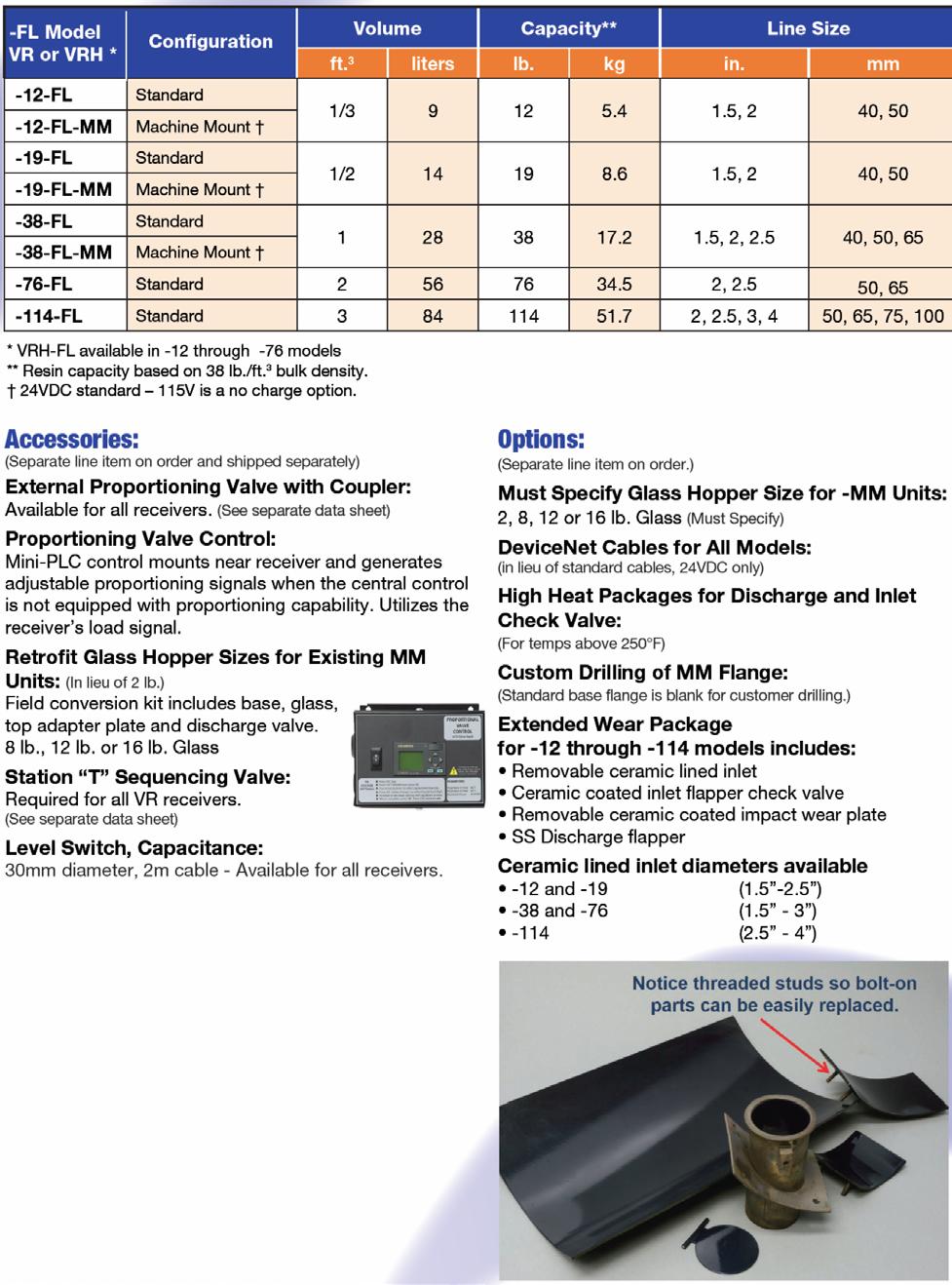
4 1-UNPACKING AND INSPECTION After receipt of the unit, completely inspect it for damage. Although the units are packaged securely, vibration and mishandling during transit can cause damage. Since receivers are part of a system and do not operate alone, examine carton carefully for accessories, wiring and spare parts that may have been included in the shipment. Check inside chambers for parts and shipping materials. 2-BASIC FUNCTIONS OF FILTERLESS VACUUM RECEIVERS NOVATEC VR-FL and VRH-FL Series vacuum receivers are vessels for the receipt of materials conveyed by a vacuum loading system consisting of a central vacuum pump, a control system and interconnected vacuum tubing. Each unit is designed to operate within a specifically pre-engineered central vacuum system and must be matched to the line size of the system (tubing diameter), control voltage and throughput capability. Each receiver must be accompanied by a range of accessories for its operation. These components are purchased separately. -control system -vacuum breaker, or T valve (Selection Valve built into VRH-FL) -tubing, bends, couplers and flex hose of the correct diameter for the vacuum system -tubing, bends, couplers and flex hose of the correct diameter for material conveying. 2.1 NOVATEC VR-FL and VRH-FL SERIES FILTERLESS RECEIVERS These NOVATEC receivers are designed to receive virgin pellets and regrind materials vacuum conveyed to them from storage containers and are typically located over drying hoppers, blenders and process machines. VR-FL & VRH-FL Series Filterless Receivers use cyclonic action to separate material from the air stream without the need for a filter or screen 2.2 OPTIONS & ACCESSORIES VR-FL and VRH-FL Options include: Alternate line sizes Alternate control voltages (in lieu of 24 VDC) DeviceNet Cables for 24 VDC High Heat Packages for materials above 225 F Alternate Glass Hopper Sizes ( for VR-MM models) VR-FL and VRH-FL Accessories Include: Proportioning valves Capacitance Level Switch Pulsed Blowback Control Field Conversion Kits for Larger Glass Hoppers 4
5 3.0 SPECIFICATIONS 5


6 4-PRINCIPLE OF OPERATION-VACUUM SYSTEMS NOVATEC central vacuum conveying systems utilize a powerful vacuum pump to create vacuum conveying power for a number of receivers. Receivers are interconnected with the vacuum pump via tubing and a control system. Each receiver in the system has the ability to use the central pump for vacuum conveying power within a sequencing arrangement...one receiver at a time. The selected conveying control system in use determines the sequence of operation and triggers vacuum isolation valves, located near or on each receiver, one at a time, to allow vacuum to flow to each receiver with a demand for a set period of time. After that receiver loads, the vacuum signal is passed onto another receiver with vacuum demand, allowing it to load. Vacuum systems typically employ a central dust collector, located near the vacuum pump. The dust collector allows material fines and dust that are carried through from each receiver to be trapped, before they are allowed to enter the pump. Filterless receivers use a cyclonic action to separate material from the air stream. The dust and fines that do pass through are be trapped by the central dust collector. In this regard, users find efficiency in two ways: 1. The conveyed materials are somewhat stripped of dust and fines by the vacuum system. These fines typically provide little value and/or actually detract from the molding process. 2. There are no filters in the receivers to be cleaned or replaced. Filterless receivers employ a cyclonic design to separate material from the airstream. 6


7 5-PRINCIPLE OF OPERATION-VACUUM RECEIVERS Each receiver is equipped with a material level switch that signals the control system with a demand for vacuum power from the central pump to load. The switch may be a tilt switch, located on the flapper valve below each receiver or in the form of an electric eye that can sense the presence or absence of material in a sight glass below the receiver. The switch is designed to signal a lack of material and the need, or demand, for the material supply to be replenished. Inlet check valve inside receiver The control system will receive the demand signal from the receiver and when it is able, send a signal to that receiver station, allowing it to load. The receiver station is equipped with a vacuum breaker that will open, allowing vacuum power to enter only that receiver, creating suction to pull its discharge flapper valve shut and pull material to the receiver from the selected material source. As material is pulled into the receiver vessel, it passes through a check valve on the receiver inlet and the receiver s chamber fills. The vacuum air used for this process is drawn through the top of the receiver back towards the central pump for the time setting established on the central control for that receiver. The cyclonic action blocks the loaded material from entering the vacuum line that exits the receiver. Once the load time setting expires, the central control turns off its signal to that receiver, allowing the vacuum breaker valve to close, shutting off the vacuum supply to that receiver. While the control system directs the vacuum signal to move on to other receivers in the system, the loaded receiver, no longer under the negative pressure of vacuum, gravity unloads its material into the vessel or machine below it. Material discharges from the chamber by gravity and flows to its destination (dryer, blender, process machine). If the loaded material completely evacuates the chamber and does not back up into the receiver, the process will repeat. This is the result of the discharge flapper on the base of the receiver, which is pushed open by the discharged material, swinging back by gravity towards closing after material is unloaded. The flapper s demand switch will indicate a new demand to the central control. If material does back up into the receiver, it will not allow the discharge flapper to swing shut. This will stop the demand switch on the flapper from sending another demand signal to the control. Once material drifts away from the flapper, the flapper will swing by gravity towards closing and once again create a demand signal. Counter-weighted flapper discharge valve with tilt demand switch. 7

8 Machine mounted units do not require a flapper valve or demand tilt switch, but instead utilize a clear sight tube, which mounts vacuum-tight to the machine throat, with a sensor to control loader operation based upon the level of material within the sight tube. In many cases, a redundant, vacuum-sealing flapper is added to the sight glass, to assure a vacuum tight seal for loading. The sensor used on machine mount sight glasses may be a capacitance type, with a sensitivity adjustment, set against the glass, or a pair of photoelectric sensing elements called an emitter and a receiver that send a signal through the glass. In either case, the function is similar to the flapper tilt switch in the way it signals the central control system when material is not present and that the receiver requires loading. Note that a sensor on the sight glass may be vertically adjustable for different levels of material in the sight glass, IE: The user can adjust at what level the receiver will call for more material. VR-MM Machine Mount with photoeye demand switch. 6-RECEIVER INSTALLATION Mount the receiver body to the hopper lid, positioning it so that the material inlet is directed towards the material pick up point or conveying line. Make sure the dump valve flapper has enough room to move freely. Secure the receiver to the hopper lid with captive bolts or clamps to ensure a safe installation with no chance of hardware vibrating loose. Ensure a tight seal when securing the loader to the hopper or machine. On machine mounted units, the bottom flange is usually supplied undrilled to allow a range of mounting patterns and hardware choices. A gasket is used to provide a tight seal between the receiver base and the machine throat. Conveying lines should be installed horizontal and/or vertical, using a 90 degree radius bend for directional changes, and it should be as direct as possible with no slope. All connections must be vacuum tight. Rigid conveying tubing should be properly supported by the installer to provide a safe and secure installation. Use flexible material handling hose to connect the material pick-up lance or vacuum take-off box to the conveying line. The flexible hose should be only as long as needed, since excess hose will reduce loader efficiency and is prone to rapid wear. 8


9 6.1 VACUUM BREAKER T VALVE INSTALLATION for VR-FL MODELS Each receiver in the vacuum loading system requires a vacuum breaker valve to be connected to it, which in turn is connected to the central vacuum header coming from the vacuum pump/dust collector. The header typically interconnects several receivers with the vacuum pump. See separate instructions for vacuum breaker valve installation. The vacuum breaker valve is the key device for directing vacuum power to the receiver for operation. On VR-FL series receivers, the vacuum breaker valve is the only electrical/pneumatic device associated with the receiver, unless other options are employed. The valve requires a connection to clean and dry compressed air, between 80 and 125 psi. The valve also requires electrical connection to the control system being Vacuum Header To lid of Receiver Pneumatic Solenoid: Connect to control Connect to compressed air Vacuum Header Vacuum Breaker T Valve used. See the central control instructions to assure that the solenoid on the vacuum breaker valve is the proper voltage and for connecting the valve solenoid coil to the control system. Connect the vacuum breaker valve to the lid of the receiver as described in the vacuum breaker valve instructions. Depending upon the installation, the valve to receiver connection can be a combination of tubing and flex hose as required, but should be kept as short as possible. The final connection to the lid of the receiver should be provided with flex hose to allow easy removal of the receiver lid for cleaning and maintenance. VRH-FL models have the selection valve built into their lid. 9


10 7-DEMAND LEVEL SWITCH WIRING Each receiver is equipped with a demand level switch that must be connected to the central control system. The switch may be in the form of a tilt switch on the discharge flapper valve, a capacitance sensor or rotating level switch, located in a bin below the receiver, a photoelectric switch on the sight glass of a machine throat receiver, or some other form. In all cases, this demand switch is required to tell the central control system when this receiver is in need of material. Since the receiver may be moved occasionally for cleaning or equipment changes, NOVATEC provides most demand switches with twist-lock connectors, allowing the receiver to be removed while the wiring to the control to can remain intact. This robust connector provides a reliable connection point for wiring to the control. The following illustrations show 24 VDC wiring details for common NOVATEC demand devices. Use these illustrations in conjunction with the wiring instructions for your central controls to carefully connect the demand switches to your control system. Reed or Mercury Switch Typical Photo-eye Demand Switch Typical Capacitance Demand Switch Typical Discharge Flapper Tilt Demand Switch CAUTION: Follow All Plant Wiring Formats and Local or National Electrical Codes. 10
11 8-INITIAL START UP 8.1 VR-FL and VRH-FL (PELLET/REGRIND) RECEIVERS: For optimum receiver operation, adjust the vacuum-on load time on the central control so that the vacuum chamber is almost completely full at the end of the load cycle. Do not allow the chamber to overfill. Adjust the dump time so the receiver is filled no higher than 4" below the material inlet. Do not overfill, or conveyed material may be inadvertently pulled through the receiver and into the vacuum manifold. 11

12 9-USE OF PROPORTIONING VALVES Proportioning valves are a convenient method for introducing regrind into the process while vacuum loading of virgin material. The proportioning valve is typically installed onto the material inlet of the receiver and is connected to the central control system, or an accessory control specifically designed for proportioning valve operation. Note that a proportioning valve should never be relied upon for accurate mixing of two materials, but are only a process convenience for loading a second material (typically regrind). An ideal use of a proportioning valve is emptying a granulator of reground material, in quantities known to not exceed the limitations or specifications of the process. If requirements for the proportioning valve require more accuracy, consult with NOVATEC regarding the use of a blender in lieu of a simple proportioning valve. External Proportioning Valve Solenoid: Connection to control and connection to compressed air supply. Material Outlet, connected to receiver Inlet Material #1 inlet, typically Regrind Material #2 inlet, typically Virgin Proportioning valves and their associated controls split the central control s vacuum-on time for a particular receiver into two parts: one for loading virgin and one for loading regrind. Making initial settings for the proportioning valve will require: 1. Determining and setting the approximate percentage of vacuum on time to be dedicated to regrind loading, based upon the specs of the product being produced. 2. Depending upon the control being used, determining and setting the approximate percentage of vacuum on time to be dedicated to virgin loading. 3. The number of valve switches (virgin/regrind/virgin/regrind, etc.) the valve will perform while vacuum loading, to encourage mixing of the two materials. 4. Increasing the vacuum-on time to compensate for use of the proportioning valve. 12
13 Be aware that use of a proportioning valve will ask the vacuum system to alternately vacuum convey two materials, and each time a material is to be loaded, it takes time to stimulate the material into motion by vacuum. This process adds valuable time to the conveying process and can create conveying problems if too many mixing cycles are set on the control. Also, the density and flow characteristics of virgin and regrind materials are typically very different, as well as the conveying distances. These factors must be taken into consideration as the percentage and number of valve cycles are set on the proportioning controls. A 50% setting of vacuum time dedicated to regrind will never equate to a 50% quantity of regrind material ending up in the receiver. It is best to make trial and error tests of proportional loads to see what results are created rather that assuming a specific outcome based purely on control settings. It is common that vacuum on time for any receiver equipped with a proportional valve must be increased to allow for the dual loading capabilities of the proportioning valve. 13
14 10-TROUBLESHOOTING 10.1 PROBLEM: POOR OR NO CONVEYING: 1. VACUUM VALVE OPERATION Each vacuum receiver in the conveying system is coupled to a vacuum T valve (or, in the case in the VRH-FL, the sequencing valve is attached to the lid) that isolates the vacuum conveying power of the pump to one receiver at a time for conveying. Each valve in the system must close off air flow when it is NOT in operation, allowing other receivers to receive full vacuum. One stuck valve can ruin the vacuum supply for the entire system. Check that each valve operates in response to its receiver s turn in the vacuum system. Each valve should open for loading and close when loading is complete. The extended shaft of the valve s cylinder is a good indication of valve operation. Rule of thumb: If only one receiver in the system is conveying correctly, it is probably that receiver s valve that is not closing properly. 2. RECEIVER DISCHARGE FLAPPER STUCK OPEN The flapper valve at the base of the receiver provides three critical functions: Seal off the base of the receiver, creating a sealed vacuum chamber and allowing it to load, Open reliably to allow material to empty out and Signal the conveying control system of the need for more material (when it swings shut, by its own weight). If the flapper valve is stuck open or does not fully close, conveying cannot take place. A problem receiver can be easily checked for proper, free movement of its flapper valve: If conveying is not triggered when the flapped is closed, there is an issue with the electrical demand switch. If the flapper does not swing nearly shut by its own weight, there is a pivot point (hinge) or counterweight issue. If the flapper is stuck in the open position, there is a material contamination issue with the pivot point (hinge) of the valve and it must be cleaned and examined for wear. Contamination of the hinge is typically caused by material, finding its way into the pivot point, but in older receivers, may also be a metal burr that has formed from age. 3. INLET CHECK VALVE STUCK OPEN Many receivers are equipped with swinging check valves on their material inlets. Check valves provide a variety of useful functions for system operation and are pushed open when material is conveyed into the receiver. But on systems that convey material from one source to multiple receivers, each check valve in the system must seal to allow the one receiver being loaded to receive the full vacuum force from the conveying pump. A check valve that is stuck open, either by hinge wear or a trapped pellet, will leak valuable vacuum air, decreasing vacuum capability at other receivers or even preventing conveying throughout the system. Rule of thumb: On systems that convey material from one source to multiple receivers via a common material line; If only one receiver in the system conveys correctly, it is probably that receiver s check valve that is not closing properly. 14
15 4. CONVEYING CONTROLS NOT PROPERLY (RE) PROGRAMMED Central material conveying systems that include a network of pumps, receivers and material sources provide high efficiency and a multitude of flexibility. But often, new requirements are not completely programmed after material or system configuration changes. Items to check: Is the new material source further away than the previous source? More conveying time and/or purge time might be required to accommodate this difference in distance. Is the new material as free-flowing as the last material? Does the material have a tendency to clog the conveying lines, or simply convey slower due to weight or shape? Changes to load/purge times as well as material pick-up tube changes may be required. Has the receiver been assigned to the proper vacuum pump? The proper material valve? Has system piping and or wiring been modified to accommodate this new configuration for conveying? 5. CONFIRM PROPER VACUUM BREAKER VALVE OPERATION Located on the central vacuum pump of the system, the vacuum breaker valve allows ambient air to be drawn into the pump when the conveying system is NOT conveying. This function prevents rapid re-starts and stops of the pump during the seek time of the loading control, cools the pump and prevents the over loads in the pump starter from over heating. But the pneumatically-operated breaker valve must close and seal when the vacuum system is conveying material, directing all vacuum force to the job of conveying. Check the following: The valve is connected to a reliable source of clean compressed air, which is turned on. Air pressure should be psi. The valve must not be leaking vacuum air. Often a sucking sound can be heard, indicating the valve is not sealing properly. View the level of vacuum created by the pump on its vacuum gage while attempting to convey material: Although the reading on this gauge will vary greatly depending upon your system configuration, it is a valuable tool for assessing system operation and discovering faults. Vacuum levels below 6 indicate a breaker valve fault or other problems in the vacuum system. 15
16 6. CHECK THE SOURCE OF YOUR MATERIAL Easily overlooked, the source of your material may be either empty or the wrong tubing or valve connections have been made. Common bulk box issues are: Rat-holing: The feed tube has sucked up all the free-flowing material around its pickup end and the material must now be stirred to allow material to flow into the feed tube again. A Gaylord tilter may be helpful in this situation. Bag liner line plugging: The feed tube has sucked in the thin film lining of the gaylord, blocking off material flow to the receiver. Feed tube fell out of the box: By weight of its own hose, or by vibration of the flex hose while conveying. Out of material: Time to move in a new bulk box. Common material selection issues: Conveying line connected to the wrong source of material: Wrong purge valve selected: If a purge valve is used at the material source, it must be programmed by the system control to operate in conjunction with a specific receiver. Material changes require making a new valve selection at the system control. Purge valve is not operating: If a purge valve is used at the material source, it must be energized to allow material loading (and de-energized for purging). A fault at this valve, IE: lost compressed air connection, an open purge valve access door or a material jammed purge valve will prevent material movement FEED TUBE / TAKE-AWAY BOX AIR SETTINGS The conveying of material by air cannot be accomplished without air movement. Regardless of the type of pickup device being used; purge valve, wand, take-off box, etc. these devices must be adjusted to allow the introduction of material and air, in a mixture suitable for conveying the specific material the distance required. 16
17 11-WARRANTY NOVATEC, INC. - Effective Date 16 DEC 2015 NOVATEC, INC. offers COMPREHENSIVE PRODUCT WARRANTIES on all of our plastics auxiliary equipment. We warrant each NOVATEC manufactured product to be free from defects in materials and workmanship, under normal use and service for the periods listed under Warranty Periods. The obligation of NOVATEC, under this warranty, is limited to repairing or furnishing, without charge, a similar part to replace any part which fails under normal use due to a material or workmanship defect, within its respective warranty period. It is the purchaser s responsibility to provide NOVATEC with immediate written notice of any such suspected defect. Warranted replacement parts are billed and shipped freight pre-paid. The purchaser must return the suspect defective part, freight prepaid and with identifying documentation to receive full credit for the part returned. NOVATEC shall not be held liable for damages or delay caused by defects. No allowance will be made for repairs or alterations without the written consent or approval of NOVATEC. The provisions in equipment specifications are descriptive, unless expressly stated as warranties. The liability of NOVATEC to the purchaser, except as to title, arising out of the supplying of the said equipment, or its use, whether based upon warranty, contract or negligence, shall not in any case exceed the cost of correcting defects in the equipment as herein provided. All such liability shall terminate upon the expiration of said warranty periods. NOVATEC shall not in any event be held liable for any special, indirect or consequential damages. Commodities not manufactured by NOVATEC are warranted and guaranteed to NOVATEC by the original manufacturer and then only to the extent that NOVATEC is able to enforce such warranty or guaranty. NOVATEC, Inc. has not authorized anyone to make any warranty or representation other than the warranty contained here. Non-payment of invoice beyond 90 days will invalidate the warranty. A renewed warranty can be purchased directly from NOVATEC. Please note that we always strive to satisfy our customers in whatever manner is deemed most expedient to overcome any issues in connection with our equipment. Warranty Period: Note: All warranty periods commence with the shipment of the equipment to the customer. VR-FL & VRP-FL Series including -MM (Machine Mount) = 1 Year Exclusions: Routine maintenance/replacement parts are excluded from the warranty. These include, but are not limited to: hoses, desiccant, filters, filter elements, wiper seals, gaskets, dew point sensors, infrared lamps, motors, internal solenoids, fuses and motor brushes. Use with abrasive materials will void the warranty of any standard product. Wear resistant options may be available to extend usable service life with abrasive materials. NOVATEC reserves the right to limit the warranty if the customer installs replacement parts that do not meet the specifications of the original parts supplied by NOVATEC. *Specific Exclusions: 1. NovaDrier warranty is void if coalescing filters are not replaced on a 6-month or yearly basis (per instruction manual) and/or membrane has been exposed to ozone. 2.Touch screen controls on NovaWheel dryers have a 2-year warranty. All other controls have a 1-year warranty 3. NovaVac Dryer -The ability of the canisters to hold vacuum will be compromised if the vacuum seal edge is damaged from mishandling. We do not warranty canisters damaged from improper handling. We do, however, warranty the seals. 4. LOAD CELLS on our WSB s are covered by NOVATEC standard warranty as long as they have not been damaged from improper handling. 5. Velocity Control Valve warranty is voided if unit is placed in direct material flow. This warranty shall not apply to equipment: 1. Repaired or altered without written approval of NOVATEC unless such repair or alteration was, in our judgment, not responsible for the failure 2. Which has been subject to misuse, negligence, accident or incorrect wiring by others 3. Warranty is void if processing rates exceed manufacturer-recommended levels or if damage is caused by ineffective power isolation and/or power spikes/sags or incorrect installation. NOTE: All conditions and content of this warranty are subject to changes without notice. 17
Vacuum Receivers with Hinged Lid VRH and VRH-MM Series
 Vacuum Receivers with Hinged Lid VRH and VRH-MM Series Models: VRH-12, VRH-19, VRH-38, VRH-76 VRH-12-MM, VRH-19-MM, VRH-38-MM VRH Series Pellet/Regrind Receivers VRH-MM Series Receivers Document: VRH IM
Vacuum Receivers VR-FL and VRH-FL Series
 Vacuum Receivers VR-FL and VRH-FL Series Models: VR-FL-12, VR-FL-19, VR-FL-38, VR-FL-76, VR-FL-114 VRH-FL-12, VRH-FL-19, VRH-FL-38, VRH-FL-76 VR-FL Series Pellet/Regrind Receivers VR-FL-MM Receivers VRH-FL
Central Vacuum Dust Collector FDC Series
 Central Vacuum Dust Collector FDC Series Models: FDC-15-ST, -20-ST, -25-ST, -30-ST, -40-ST See-through Canister Discharge Model Drum Dump Model 2015 2016 NOVATEC, Inc. Inc. All Rights All Rights Reserved
Vacuum Receivers VR and VRP Series
 Vacuum Receivers VR and VRP Series Models: VR-5, VR-12, VR-19, VR-38, VR-76, VR-114 VRP-12, VRP-19, VRP-38, VRP-76 VR Series Pellet/Regrind Receivers VRP Series Powder Receivers Document: Document: VR-VRP
Vacuum Receivers VR and VRP Series
 Vacuum Receivers VR and VRP Series Models: VR-5, VR-8, VR-12, VR-19, VR-38, VR-76, VR-114 VRP-12, VRP-19, VRP-38, VRP-76 VR Series Pellet/Regrind Receivers VR-MM Series Receivers VRP Series Powder Receivers
VACUUM LOADERS GSL Series
 VACUUM LOADERS GSL Series Models: GSL-19 & GSL-19-MM (Patent Pending) GSL-19 GSL-19 Tilted GSL-19-MM Machine Mount Instruction Manual GSL 9-12-12 IM Doc. GSL IM 8-21-12 Page 1 NOTES: Please record the
VACUUM LOADERS GSL Series
 VACUUM LOADERS GSL Series Models: GSL-12 & GSL-12-MM GSL-19 & GSL-19-MM Patent # 8,753,432 and 8,070,844 GSL-19 GSL-19 Tilted GSL-19-MM Machine Mount NOVATEC, INC. 2016 All Rights Reserved Instruction
Vacuum Receivers VR and VRP Series
 Vacuum Receivers VR and VRP Series Models: VR-5, VR-8, VR-12, VR-19, VR-38, VR-76, VR-114 VRP-12, VRP-19, VRP-38, VRP-76 VR Series Pellet/Regrind Receivers VR-MM Series Receivers VRP Series Powder Receivers
Vacuum Receivers VR and VRP Series
 Vacuum Receivers VR and VRP Series Models: VR-5, VR-8, VR-12, VR-19, VR-38, VR-76, VR-114 VRP-12, VRP-19, VRP-38, VRP-76 VR Series Pellet/Regrind Receivers VR-MM Series Receivers VRP Series Powder Receivers
COMPRESSED AIR LOADER MODEL: AL-1
 COMPRESSED AIR LOADER MODEL: AL-1 Novatec, Inc. 2018 All rights Reserved Document: AL-1 IM 7 FEB 2018 NOTES: Please record the following information, which is specific to this piece of equipment, in the
HB CDA SERIES WITH TEMPERATURE SETBACK
 HB CDA SERIES WITH TEMPERATURE SETBACK 2013 NOVATEC, Inc. All Rights Reserved Document: HB CDA IM 7-24-2013 NOTES: Please record the following information, which is specific to this piece of equipment,
POD Silo Dehumidifier Series. with Logo! TM PLC POD-150 DOCUMENT: POD IM 14 DEC NOVATEC, Inc All Rights Reserved
 POD Silo Dehumidifier Series with Logo! TM PLC POD-150 NOVATEC, Inc. 2016 All Rights Reserved DOCUMENT: 2012 Novatec, Inc. All Rights Reserved Page 2 VL-VLP IM 10-24-2012 NOTES: Please record the following
Central Vacuum Dust Collector FDC Series
 Central Vacuum Dust Collector FDC Series Models: FDC-15-ST, -20-ST, -25-ST, -30-ST, -40-ST See-through Canister Discharge Model Drum Dump Model 2018 NOVATEC, Inc. All Rights Reserved Document: FDC IM 8
MCS-401A MCS-401 SINGLE STATION CONTROL PACKAGE
 MCS-401A MCS-401 SINGLE STATION CONTROL PACKAGE MCS-401-A 115 VAC I/O MCS-401A 24 VDC I/O NOVATEC, Inc. 2018 All Rights Reserved MCS-401A-MCS-401 IM 10 FEB 2018 NOTES: Please record the following information,
NovaDrier MEMBRANE DRYER for Plastics
 NovaDrier MEMBRANE DRYER for Plastics MODEL NDM Model NDM Shown with l HEPA Filter Document: NDM IM 14 DEC NOTES: Please record the following information, which is specific to this piece of equipment,
NDB-15 through NDB-50
 NDB-15 through NDB-50 NDB-25 NOVATEC, Inc. 2018 All Rights Reserved DOCUMENT: NDB-15-50 IM 28 FEB 2018 Page 1 of 2 NOTES: Please record the following information, which is specific to this piece of equipment,
POD Silo Dehumidifier Series. with Logo! TM PLC POD-150 DOCUMENT: POD IM 15 MAY NOVATEC, Inc All Rights Reserved.
 POD Silo Dehumidifier Series with Logo! TM PLC POD-150 NOVATEC, Inc. 2017 All Rights Reserved DOCUMENT: POD IM 15 MAY 2017 Page 1 of 2 NOTES: Please record the following information, which is specific
VACUUM LOADERS VL and VLP Series
 VACUUM LOADERS VL and VLP Series Models: VL-5, VL-12, VL-19, VL-38 VLP-5, VLP-12, VLP-19, VLP-38 VL-12 Model Pellet and Regrind Loader VL-5-MM Machine Mount Pellet Loader VLP-38 Model Powder Loader Mini
NDM-5 MEMBRANE DRYER for Plastics
 NDM-5 MEMBRANE DRYER for Plastics MODEL NDM Model NDM Shown with HEPA Filter NOTE: See important information about air supply on next page. Copyright 2018 NOVATEC, Inc. All rights reserved. Document: NDM
INSTRUCTION MANUAL. CDA2 Series. Central Drying Hopper Assembly with OverDry Protection
 INSTRUCTION MANUAL I CDA2 Series Central Drying Hopper Assembly with OverDry Protection 2017 Novatec, Inc. All Rights Reserved Instruction Manual: CDA2 IM 15 MAY 2017 222 E. Thomas Ave. Baltimore, MD 21225
NovaDrier MEMBRANE DRYER for Plastics
 NovaDrier MEMBRANE DRYER for Plastics MODELS: ND-7, ND-25, ND-50, ND-75, ND-100, ND-150, ND-200 U.S. Patent No. US 6,584,701 B1 NOTE: See important information about air supply on next page. NOVATEC, Inc.
TLR Model Tube Loaders
 U S E R G U I D E UGC014-0903 TLR Model Tube Loaders Hopper Loading and Direct Feed Configurations www.conairgroup.com Corporate Office: 724.584.5500 l Instant Access 24/7 (Parts and Service): 800.458.1960
Dust Collector. Sizes DC1 and DC2 U S E R G U I D E UGC
 U S E R G U I D E UGC033-0194 www.conairgroup.com Dust Collector Sizes DC1 and DC2 Corporate Office: 724.584.5500 l Instant Access 24/7 (Parts and Service): 800.458.1960 l Parts and Service: 814.437.6861
INSTRUCTIONS FOR TAL SERIES VACUUM HOPPER LOADER
 INSTRUCTIONS FOR TAL SERIES VACUUM HOR LOADER TAL-15U 150 LBS PER HOUR MAGNETIC LEVEL SWITCH TAL-3U-E 450 LBS PER HOUR SIGHT GLASS WITH PROXIMITY LEVEL SWITCH Proportional Dual Feed Valve Available TAL-6U
MODEL MPM-2 MPM-9 MPM-18 MPM-50 LIQUID COLOR PRE-MIXER
 MODEL MPM-2 MPM-9 MPM-18 MPM-50 LIQUID COLOR PRE-MIXER INSTURCTION MANUAL rev. 102715 1 INSTALLATION INSTRUCTIONS 1. Remove the material hopper from your process machine. 2. Select the best orientation
EZLoad Models EZL-2 and EZL-5
 U S E R G U I D E UGC047-0815 www.conairgroup.com EZLoad Models EZL-2 and EZL-5 Corporate Office: 724.584.5500 l Instant Access 24/7 (Parts and Service): 800.458.1960 l Parts and Service: 814.437.6861
CAR-MON DUST COLLECTORS SERIES 207, 2410, 3015
 INSTALLATION-OPERATION-MAINTENANCE CAR-MON DUST COLLECTORS SERIES 207, 2410, 3015 TEFC 3 phase motor Outlet duct Fan wheel housing Inlet duct connection After filter transition Optional after filter unit
Central Vacuum Receivers
 USER GUIDE UGC046-0316 www.conairgroup.com Central Vacuum Receivers DuraLoad (DL), Filterless (FL), K-Loader Corporate Office: 724.584.5500 l Instant Access 24/7 (Parts and Service): 800.458.1960 l Parts
Compressed Air Dryer
 Compressed Air Dryer INSTRUCTION MANUAL IB200602 THORESON-McCOSH INC 1885 Thunderbird St. Troy MI. 48084 Phone 1-248-362-0960 Fax 1-248-362-5270 sales@thoresonmccosh.com parts@thoresonmccosh.com FORWARD
Standard and CELDEK Evaporative Cooler Modules Installation, Operation, and Maintenance Manual
 Standard and CELDEK Evaporative Cooler Modules Installation, Operation, and Maintenance Manual Standard Evaporative Cooler CELDEK Evaporative Cooler RECEIVING AND INSPECTION Upon receiving unit, check
FlexTouch. Siemens FTS-320-6RC-4C Recycle Collection System Control 4 Color Touch Screen PLC. Document: FTS-RC IM 8 FEB 2018
 FlexTouch Siemens FTS-320-6RC-4C Recycle Collection System Control 4 Color Touch Screen PLC 2018 Novatec Inc. All Rights Reserved Document: FTS-RC IM 8 FEB 2018 Novatec, Inc. 2017 All rights reserved NOTES:
Standard and CELDEK Evaporative Cooler Modules Installation, Operation, and Maintenance Manual
 Standard and CELDEK Evaporative Cooler Modules Installation, Operation, and Maintenance Manual Standard Evaporative Cooler CELDEK Evaporative Cooler RECEIVING AND INSPECTION Upon receiving unit, check
MULTI-FUNCTION HAND VACUUM INSTRUCTION MANUAL. For Authentic Monster Replacement Parts Call Model #: H056
 MULTI-FUNCTION HAND VACUUM INSTRUCTION MANUAL Call 888.896.8786 Model #: H056 IMPORTANT SAFE T SAVE THESE INSTRUCTIONS When using an electrical appliance, basic safety precautions should always be observed,
NovaWheel DESICCANT WHEEL DEHUMIDIFYING DRYER INSTRUCTION MANUAL
 NovaWheel DESICCANT WHEEL DEHUMIDIFYING DRYER INSTRUCTION MANUAL NW Series with NovaTouch Touch Panel PLC Models: NW-600NC thru NW-2000NC Dedicated Dryers & NW-600NC-C through NW-2000 NC-C Central Dryers
ingle phase three phase hoppers central systems single phase three phase hoppers central syste CONVEYING
 ingle phase three phase hoppers central systems single phase three phase hoppers central syste CONVEYING Venturi Loader NMS-114 The Venturi hopper loader s compact, lightweight and simple design makes
Conveying Controls. Conveying, Drying and Blending Systems. Technical Service Available 24/7! D C F. For Extrusion, Injection and Blow Molding Plants
 Conveying Controls 5-YEAR WARRANTY ON ALL NOVATEC DRYERS Micro Dryers Process 15-50 lb./hr (7-23 kg/hr.) Portable Drying/Conveying System Process 15-200 lb./hr. (7-90 kg/hr.) Dual-bed efficiency in a compact
HANDY/STICK 2-WAY VACUUM INSTRUCTION MANUAL. For Authentic Monster Replacement Parts Call Model #: H055
 HANDY/STICK 2-WAY VACUUM INSTRUCTION MANUAL For Authentic Monster Replacement Parts Call 888.896.8786 Model #: H055 IMPORTANT SAFE T SAVE THESE INSTRUCTIONS When using an electrical appliance, basic safety
CELDEK Evaporative Cooler Module Installation, Operation, and Maintenance Manual. CELDEK Evaporative Cooler
 CELDEK Evaporative Cooler Module Installation, Operation, and Maintenance Manual CELDEK Evaporative Cooler RECEIVING AND INSPECTION Upon receiving unit, check for any interior and exterior damage, and
TLM Model Tube Loaders
 TLM Model Tube Loaders Hopper Loading and Direct Feed Configurations with MLC2 Control Installation Operation Maintenance Troubleshooting TLM Tube Loader Hopper Loader Configuration Instant Access Parts
Gas-Fired Heater with NovaTouch PLC Interface
 Gas-Fired Heater with NovaTouch PLC Interface Models: GFH-500 GFH-750 GFH-1000 NOVATEC, Inc. 2016 All Rights Reserved Document: GFH-NT 500-1000 IM 14 DEC 2016 TABLE OF CONTENTS 1.0 ENGINEERING DATA 5 1.1
WATLOW IND. WATROD Modular Duct Heater Installation & Maintenance Manual I&M NUMBER: Page: 1 Date:6/11/2008 Rev: 2
 I&M NUMBER: 316-42-15-1 Page: 1 _ Pre Installation Check to make sure that heater received is the same as that ordered. Elements may come in contact with each other during shipment. Minor adjustments to
Advanced Resin Handling, Drying and Downstream Extrusion Systems for the Plastics Industry
 Advanced Resin Handling, Drying and Downstream Extrusion Systems for the Plastics Industry Resin Handling & Conveying Vacuum Pumps Up to 25 hp UVP VPDB VRB SVP Lower Noise NEW! Station T Sequencing Valve
SANI-VAC MODEL #750 WARNING! FOR YOUR SAFETY PLEASE READ INSTRUCTIONS BEFORE OPERATING TOOL. & WEAR EYE PROTECTION
 MODEL #750 SANI-VAC WARNING! FOR YOUR SAFETY PLEASE READ INSTRUCTIONS BEFORE OPERATING TOOL. & WEAR EYE PROTECTION INSPECTION Open the container in which the Sani-Vac was shipped and inspect it. Should
! The Caution Symbol (exclamation point) alerts you to a "CAUTION", a safety or
 alerts you to a CAUTION, a safety or") I&M NUMBER: 316-42-10-1 Page: 1 Pre Installation Check to make sure that heater received is the same as that ordered. Elements may come in contact with each other during shipment. Minor adjustments to
I&M NUMBER: 316-42-10-1 Page: 1 Pre Installation Check to make sure that heater received is the same as that ordered. Elements may come in contact with each other during shipment. Minor adjustments to
Quick-Start Operating Guide Document No Acrylic Vacuum Chambers Copyright 2010 Terra Universal Inc. All rights reserved. Revised October 2010
 Document No. 1800-60 Acrylic Vacuum Chambers Copyright 2010 Terra Universal Inc. All rights reserved. Revised October 2010 Terra Universal, Inc. TerraUniversal.com 800 S. Raymond Ave. Fullerton, CA 92831
CONVEYING. Central conveying systems for granulate METRO G
 Central conveying systems for granulate CENTRAL CONVEYING SYSTEMS FOR GRANULATE 15I-HCG 30I-HSS 06I-HCG 05I-HPS is the most comprehensive and flexible material loader range on the market. It combines the
Air Pump Up to 800 gallons
 Air Pump Up to 800 gallons REMINDER CALL 1-888-755-6750 BEFORE RETURNING TO STORE. PACKAGE CONTENTS ITEM #PBPAPK40W Questions, problems, missing parts? Before returning to your retailer, call our customer
WATLOW IND. FIREBAR Flange Heater Installation & Maintenance Manual I&M NUMBER: Page: 1 Date: 6/11/2008 Rev: 2.00
 I&M NUMBER: 316-42-2-1 Page: 1 Pre Installation Check to make sure that heater received is the same as that ordered. Elements may come in contact with each other during shipment. Minor adjustments to elements
Owner s Manual PCS PRO
 Owner s Manual PCS PRO Designed and Manufactured Exclusively by Ozotech, Inc. M43-31017 REV A Table of Contents 1.0 Limited Warranty 3 2.0 Service Returns 4 3.0 Caution 5 4.0 Theory of Operation 5 4.1
Level Alarm Control. Blender Accessories U S E R G U I D E UGB
 www.conairgroup.com U S E R G U I D E UGB015-1007 Level Alarm Control Blender Accessories Corporate Office: 724.584.5500 Instant Access 24/7 (Parts and Service): 800.458.1960 Parts and Service: 814.437.6861
92831 TEL: (714) FAX:
 FAX:") Document No. 1800-11 High-Performance Vacuum/Nitrogen Copyright 2010 Terra Universal Inc. All rights reserved. Revised October 2010 Terra Universal, Inc. TerraUniversal.com 800 S. Raymond Ave. Fullerton,
Document No. 1800-11 High-Performance Vacuum/Nitrogen Copyright 2010 Terra Universal Inc. All rights reserved. Revised October 2010 Terra Universal, Inc. TerraUniversal.com 800 S. Raymond Ave. Fullerton,
WATLOW ELECTRIC MFG CO. FIREBAR Screw Plug Installation & Maintenance Manual I&M NUMBER: Page: 1 Date: 11/25/2013 Rev: 4.
 I&M NUMBER: 316-42-3-1 Page: 1 Pre Installation Check to make sure that heater received is the same as that ordered. Elements may come in contact with each other during shipment. Minor adjustments to elements
WATLOW IND. WATROD Flange Heater Installation & Maintenance Manual I&M NUMBER: Page: 1 Date:6/11/2008 Rev: 2.00
 I&M NUMBER: 316-42-8-1 Page: 1 _ Pre Installation Check to make sure that heater received is the same as that ordered. Elements may come in contact with each other during shipment. Minor adjustments to
Installation and Operations Manual
 Installation and Operations Manual H-IM-LLC February 2018 Part No. 25092501 Replaces H-IM-LLC (01/2014) Lead Lag Control System Table of Contents General Safety Information 2 Inspection 2 Warranty Statement
INSTALLATION INSTRUCTIONS
 INSTALLATION INSTRUCTIONS FOR AQUECOIL HYDRONIC HEATING UNITS GENERAL INFORMATION The AQUECOIL Hydronic Heating Unit is offered in many different capacities and physical configurations in order to match
Air Dryers & After Coolers Dry Land
 Air Dryers & After Coolers Dry Land See limited warranty documentation for complete details Air Dryers Features Pirate Brand Dry Land air dryers are the perfect solution for the mobile blasting and painting
WATLOW IND. WATROD Circulation Heater Installation & Maintenance Manual I&M NUMBER: Page: 1 Date: 6/11/2008 Rev: 2.00
 I&M NUMBER: 316-42-5-1 Page: 1 Pre Installation Check to make sure that heater received is the same as that ordered. Watlow heaters are built to comply with UL and CSA dielectric requirements, it may be
WATLOW ELECTRIC MFG CO. WATROD Duct Heater (module only) I& M Manual I&M NUMBER: Page: 1 Date: 11/25/2013 Rev: 4.00
 I& M Manual I&M NUMBER: Page: 1 Date: 11/25/2013 Rev: 4.00") I&M NUMBER: 316-42-16-1 Page: 1 Pre Installation Check to make sure that heater received is the same as that ordered. Elements may come in contact with each other during shipment. Minor adjustments to
I&M NUMBER: 316-42-16-1 Page: 1 Pre Installation Check to make sure that heater received is the same as that ordered. Elements may come in contact with each other during shipment. Minor adjustments to
InstructIon Manual KrEs EQuIPMEnt stands
 Instruction Manual Instruction Manual SELF-CONTAINED AND REMOTE Kairak KRES model refrigerated equipment stand units are available in many lengths from 36 to 120 inches long. These units are available
WET/DRY VACUUM. QUEST for Continuous Improvement Windsor s Quality Management System is Certified ISO MODEL: T1. Operating Instructions (ENG)
") WET/DRY VACUUM Operating Instructions (ENG) MODEL: T1 y QUEST for Continuous Improvement Windsor s Quality Management System is Certified ISO 9001. Read these instructions before operating the machine.
WET/DRY VACUUM Operating Instructions (ENG) MODEL: T1 y QUEST for Continuous Improvement Windsor s Quality Management System is Certified ISO 9001. Read these instructions before operating the machine.
Industrial Vacuums, Inc
 Instructions/Spare Parts Manual Nilfisk Model GWD255 Drum Top Vacuum CAUTION: This Nilfisk vacuum cleaner is not to be used in explosion-hazardous areas, as serious injury could result. Under no circumstances
NovaWheel DESICCANT WHEEL DEHUMIDIFYING INSTRUCTION MANUAL
 NovaWheel DESICCANT WHEEL DEHUMIDIFYING INSTRUCTION MANUAL Models: NW-500NC thru NW-5000NC Stand Alone Dryers & NW-500NC-C through NW-5000NC-C Central Dryers All With 7 NovaTouch Color Touch Panel PLC
Advanced Resin Handling, Drying and Downstream Extrusion Systems for the Plastics Industry
 Advanced Resin Handling, Drying and Downstream Extrusion Systems for the Plastics Industry Experience the Power of Touch Patent Pending Machine Component Wearables Wireless Data Capture and Cloud Based
Model OP155 Air Dryer
 "Teamwork & Communication" Model OP155 Air Dryer Operating Manual with Parts Identification OP155-INST June 15, 1998 Issue 2 GUSMER CORPORATION A Subsidiary of Gusmer Machinery Group, Inc. One Gusmer Drive
Cat 5 Pro Vacuum OPERATOR S MANUAL
 Cat 5 Pro Vacuum OPERATOR S MANUAL Concrete Polishing Solutions PO Box 520 * Norris, TN 37828 Phone: (865) 494-8200 * Fax: (865) 494-8300 Toll Free: (877) 472-8200 * www.go2cps.com Table Of Contents General
Getz Equipment Innovators 450 lb Dual Portable Dry Chemical Fill System
 Getz Equipment Innovators 450 lb Dual Portable Dry Chemical Fill System 1 Revised 11/18/10 2320 Lakecrest Drive, Pekin IL 61554 PH. (888) 747-4389 Fax (309) 495-0625 Website: www.getzequipment.com LIMITED
Ui REFRIGERATOR SPEC SHEET
 Ui REFRIGERATOR SPEC SHEET ISOMETRIC VIEW 19 7/8 20 1/2 32 3/4 FRONT VIEW NOTES: 1. CUTOUT DIMENSIONS: 20 1/2"W X 33"L X 20 3/4"D 2. CUTOUT DIMENSIONS ARE FOR REFRIGERATOR ONLY. REFER TO STAINLESS STEEL
INSTRUCTIONS FOR HL-9 HOPPER LOADER HL-9 PPE SOUTH
 INSTRUCTIONS FOR HL-9 HOR LOADER HL-9 MODEL NO. SERIAL NO. Hopper Loaders are manufactured and sold direct by Plastic Process Equipment, Inc. We are not associated with any other manufacturer. Always specify
RemoteVac Hopper Loader
 Never clean a filter! No dust on your machine or any where else! No more climbing up ladders to lift heavy motors and clean filters Competitive pricing. Super quiet operation. Large self-cleaning filters.
Introduction... 1 System Overview... 1 System Diagram... 2
 TABLE OF CONTENTS Introduction... 1 System Overview... 1 System Diagram... 2 Installation... 3 Console Mounting... 3 Monitor And Power Connections... 3 ASM II Console Main Harness... 4 Module Mounting...
BL250. Pulse Blender OWNER S GUIDE
 BL250 OWNER S GUIDE Pulse Blender 1-877-646-5288 IMPORTANT SAFETY INSTRUCTIONS For Household Use Only WHEN USING ELECTRICAL APPLIANCES, BASIC SAFETY PRECAUTIONS SHOULD ALWAYS BE FOLLOWED, INCLUDING THE
Upholstery and Drapery Cleaner. Operator and Parts Manual. Model No.: gal Extractor. MNL32506 Rev. 00 (08-98)
") 32506 Upholstery and Drapery Cleaner Model No.: 32506 3 gal Extractor Operator and Parts Manual KLEENRITE 1122 MAPLE STREET MADERA CA 93637 U.S.A. FAX: 1-559-673-5725 CUSTOMER SERVICE: 1-800-241-4865 MNL32506
32506 Upholstery and Drapery Cleaner Model No.: 32506 3 gal Extractor Operator and Parts Manual KLEENRITE 1122 MAPLE STREET MADERA CA 93637 U.S.A. FAX: 1-559-673-5725 CUSTOMER SERVICE: 1-800-241-4865 MNL32506
DBF 4XL Dryer Booster Fans
 Installation and Operation Manual Item #: 401315 Rev Date: 050814 DBF 4XL Dryer Booster Fans DBF4XL Kit Includes: Dryer Booster Fan, 1 pc Fan Mounting Bracket and Hardware, 1 pc Wall Label (Mount on wasll
Air Cleaning Equipment, Inc. 303 N. Main St. Broadway, NC iers.com
 Read and Save These Instructions Horizon Galaxy - Installation and Operations Manual Air Cleaning Equipment, Inc. 303 N. Main St. Broadway, NC 27505 www.horizondehumidif iers.com 1 Safety Notes: The Horizon
Desiccant Tank Retrofit Kit for CD100/CS101 dehumidifying dryers
 Desiccant Tank Retrofit Kit for CD100/CS101 dehumidifying dryers Installation Instructions Instant Access Parts and Service (800) 458-1960 (814) 437-6861 www.conairnet.com The Conair Group, Inc. One Conair
DESCRIPTIVE AND INSTALLATION INSTRUCTION MANUAL FOR MODEL G1000 AND H1000 SERIES ANNUNCIATORS
 DESCRIPTIVE AND INSTALLATION INSTRUCTION MANUAL FOR MODEL G1000 AND H1000 SERIES ANNUNCIATORS SEEKIRK, INC. 2420 Scioto Harper Dr. Columbus, OH 43204 Tel: (614) 278-9200 FAX: (614) 278-9257 email: seekirk@seekirk.com
Operator s Manual. IP-100 Immersion Probe Cooler
 Operator s Manual IP-100 Immersion Probe Cooler 110-810 04.27.11 Table of Contents Introduction... 3 General Information... 3 General Safety Information... 3 Safety Recommendations... 4 Unpacking Your
PROTEK DRYER CONTROLS
 PROTEK DRYER CONTROLS INSTRUCTION MANUAL IB201501. 1885 Thunderbird Street, Troy, Mi. 48084 Phone 248.362.0960 FAX 248.362.5270 www.thoresonmccosh.com sales@thoresonmccosh.com FORWARD Installation, Operation
Installation & Operation Manual Ice Cream Freezers
 Installation & Operation Manual Ice Cream Freezers Please read this manual completely before installing or operating this unit! BACF11 BACF15 Blue Air reserves the right to make product modification at
INSTRUCTIONS FOR HL-3 HOPPER LOADER HL-3 PPE SOUTH
 INSTRUCTIONS FOR HL-3 HOR LOADER HL-3 MODEL NO. SERIAL NO. Hopper Loaders are manufactured and sold direct by Plastic Process Equipment, Inc. We are not associated with any other manufacturer except Budget
DRY AIR SYSTEMS, INC Metro Boulevard Maryland Heights, Missouri (314) fax (314)
 fax (314)") DRY AIR SYSTEMS, INC. 2655 Metro Boulevard Maryland Heights, Missouri 63043 (314) 344-1114 fax (314) 344-0677 HD SERIES DRIERS TABLE OF CONTENTS WHY AN AIR DRYER 3 WHAT IS A DESICCANT AIR DRYER 3 Desiccant
DRY AIR SYSTEMS, INC. 2655 Metro Boulevard Maryland Heights, Missouri 63043 (314) 344-1114 fax (314) 344-0677 HD SERIES DRIERS TABLE OF CONTENTS WHY AN AIR DRYER 3 WHAT IS A DESICCANT AIR DRYER 3 Desiccant
USER S OPERATING AND INSTRUCTION MANUAL
 Grand Rapids, Michigan, U.S.A. 49504-5298 USER S OPERATING AND INSTRUCTION MANUAL MODEL 1508-NLG SELF-ACTUATING TRAY LIDDER 1508S20000CV2 INDEX SAFETY INSTRUCTIONS... 1508S20002 SET UP... 1508S20003 OPERATING
DUAL VOLTAGE REFRIGERATORS 220/240 VOLTS AC AND 12/24 VOLTS DC INSTALLATION AND OWNER S MANUAL
 DUAL VOLTAGE REFRIGERATORS 220/240 VOLTS AC AND 12/24 VOLTS DC INSTALLATION AND OWNER S MANUAL Service Information If service or parts are required, contact the nearest Norcold Service Center. To find
IMPORTANT INFORMATION - PLEASE READ CAREFULLY
 Honeywell Garrett Direct Fit Performance Intercooler 2015+ 3.5L / 2.7L Ford F150 EcoBoost Bill of Materials and Precautions Application: 2015+ Ford F150 3.5L / 2.7L Eco Boost Part Number: 870702-6001 Part
Inline Heater for Solvent or Gas. Installation and Operation Manual
 SH Series Inline Heater for Solvent or Gas Installation and Operation Manual This instruction manual explains the basic operation of the Process Technology inline solvent or gas heater. We recommend reading
Silo Manager: CL Analog Silo Controllers For up to 12 Silos
 Silo Manager: CL Analog Silo Controllers For up to 12 Silos 2018 Novatec, Inc. All Rights Reserved Instruction Manual CL IM 8 FEB 2018 Contents Table of Contents 1.0 OVERVIEW... 4 2.0 HARDWARE... 4 2.1
BlendingLine. MINICOLOR V MINICOLOR G GRAVICOLOR Dosing and mixing units. smart solutions
 BlendingLine smart solutions MINICOLOR V MINICOLOR G GRAVICOLOR Dosing and mixing units Excellent mixing quality with highest repeatability are demanding requirements when dosing additives and regrind
OPERATING INSTRUCTIONS AND MAINTENANCE MANUAL
 OPERATING INSTRUCTIONS AND MAINTENANCE MANUAL SSCOR/board SUCTION FOR THE EMS VEHICLE SSCOR, INC. 11064 Randall Street Sun Valley, CA 91352 USA Telephone +1-818-504-4054 800-434-5211 Fax +1-818-504-6032
Bag-In-A-Box Oil Pump System
 Bag-In-A-Box Oil Pump System Instruction Manual Model #2245 and Model #2246 Part No. 79212 Revised June 1996 Cincinnati, OH 45241-4807 USA SAFETY PRECAUTIONS This equipment is designed and sold for commercial
installation, operation & Maintenance manual Floor-mounted Induction units acb 30/35
 installation, operation & Maintenance manual Floor-mounted Induction units acb 30/35 built on innovation acb 30 & 35 Active Chilled Beam Models ACB30 & ACB35 are designed for installation in the ceiling
IAQ Series. Bosch IAQ Photo Catalytic Oxidizer (PCO) Residential Application. Installation Manual and Owner s Guide
 Residential Application. Installation Manual and Owner s Guide") Installation Manual and Owner s Guide IAQ Series Bosch IAQ Photo Catalytic Oxidizer (PCO) Residential Application PCOB-09012-0--A - 9" PCO BULB PCOB-14024-0--A - 14" PCO BULB 67202220344 Revised 07-12
Installation Manual and Owner s Guide IAQ Series Bosch IAQ Photo Catalytic Oxidizer (PCO) Residential Application PCOB-09012-0--A - 9" PCO BULB PCOB-14024-0--A - 14" PCO BULB 67202220344 Revised 07-12
venting method will work for all pressure conveying systems, analyzing your available equipment, your material s characteristics, and your conveying c
 Six practical ways to handle rotary leakage Jonathan O. Thorn MAC Equipment Because of the way a rotary is designed, it s normal for a small amount of conveying to leak back through the as it s bulk solid
HDLV 55-Gallon Powder Drum Unloader
 Instruction Sheet P/N 07333 0 HDLV -Gallon Powder Drum Unloader Description See Figure. The HDLV -gallon powder drum unloader uses a Prodigy HDLV High Capacity pump to supply virgin powder to a powder
THE BARCLAY HUGGER CEILING FAN INSTALLATION INSTRUCTIONS
 THE BARCLAY HUGGER CEILING FAN INSTALLATION INSTRUCTIONS Please read and save these instructions These instructions are to be used in the installation of the following QUORUM INTERNATIONAL fans... The
WKS 4000 SERIES (USA only) --INSTALLATION INSTRUCTIONS--
 --INSTALLATION INSTRUCTIONS--") 8610 Production Avenue San Diego, California 92121 (858) 566-7465 Fax (858) 566-1943 WKS 4000 SERIES (USA only) --INSTALLATION INSTRUCTIONS-- Thank you for choosing a BREEZAIRE cooling unit. We believe
8610 Production Avenue San Diego, California 92121 (858) 566-7465 Fax (858) 566-1943 WKS 4000 SERIES (USA only) --INSTALLATION INSTRUCTIONS-- Thank you for choosing a BREEZAIRE cooling unit. We believe
MANUAL 8/12/05. Model BKP TM 100 INSTALLATION, OPERATION & MAINTENANCE. Commercial High Efficiency Heat Pipe Dehumidifier
 MANUAL 8/12/05 INSTALLATION, OPERATION & MAINTENANCE Commercial High Efficiency Heat Pipe Dehumidifier Model BKP TM 100 Heat Pipe Technology, Inc. 6904 Parke East Blvd. Tampa FL 33610 Tel: (813) 470-4250
installation, operation & Maintenance manual Floor-mounted Induction units
 installation, operation & Maintenance manual Floor-mounted Induction units built on innovation induction units- fmfby/ fmlby/ fmtby Floor-mounted induction units FMFBY, FMLBY, & FMTBY are designed for
Milk Coolers Installation and Operation Manual Please read this manual completely before attempting to install or operate this equipment!
 Turbo Air Speed up the Pace of Innovation CAUTION! PLEASE KEEP POWER SWITCH ON BEFORE OPERATING THIS EQUIPMENT Milk Coolers Installation and Operation Manual Please read this manual completely before attempting
Panel Mounted Heat Exchangers by Dantherm, Inc.
 Panel Mounted Heat Exchangers by Dantherm, Inc. PRODUCT INFORMATION MANUAL C0028 003 Pinnacle OM Manual Rev AB Page 1 of 14 Dantherm, Inc. 110 Corporate Drive, Suite K Spartanburg, SC 29303 Tel # +1 864
Horizontal Bottle Cooler Installation and Operation Manual
 Speeds Up the Pace of Innovation Horizontal Bottle Cooler Installation and Operation Manual Please read this manual completely before attempting to install or operate this equipment! TBC-50SD, 50SB/ TBC-95SD,