A/23 MFFI - A/27 MFFI
|
|
|
- Louisa Benson
- 5 years ago
- Views:
Transcription
1 A/23 MFFI - A/27 MFFI G.C.N / Servicing Instructions Type C Boilers LEAVE THESE INSTRUCTIONS ADJACENT TO THE GAS METER
2 TABLE OF CONTENTS Page No.. SERVICING INSTRUCTIONS. Replacement of Parts 3.2 To Gain General Access - Removing the Front Panel 3 - Removing the Side Panels 4 - To Lower the Control Panel 4.3 Access to the Combustion Chamber - Removing the Sealed Combustion Chamber 5 - Removing the Burner and Injectors 5 - Removing the Electrodes 6 - Removing the Main Heat Exchanger 7 - Removing the Air Pressure Switch 7 - Removing the Venturi Device 8 - Removing the Fan 8.4 Servicing and Removal of the Gas Valve - Setting Gas Pressure 9 - Removing the Spark Ignitor - Removing the Gas Valve 2.5 Access to the Hydraulic Circuit - Removing the D.H.W. (Secondary) Exchanger 2 - Removing the Safety Valve 3 - Removing the Automatic Air Vent 3 - Removing the Main Flow Circuit Switch 3 - Removing the Pump 4 - Removing the Pressure Gauge 4 - Removing the Expansion Vessel 5 - Removing the Overheat Thermostat 5 - Removing the Heating Temperature Sensor (N.T.C.) 5.6 Access to the Control System - Checking the Fuses 6 - Removing the Time Clock 6 - Removing the P.C.B.s 7 2. FAULT FINDING 2. Fault Finding Guide (Flow-chart) Fault Finding Using the Total Check System ELECTRICAL DIAGRAMS 3. Electrical Connection Functional Flow Connection SHORT SPARE PARTS LIST 26 2 B029

.")
3 . SERVICING INSTRUCTIONS To ensure efficient safe operation, it is recommended that the boiler is serviced annually by a competent person. Before starting any servicing work, ensure both the gas and electrical supplies to the boiler are isolated and the boiler is cool. Before and after servicing, a combustion analysis should be made via the flue sampling point (please refer to the Installation Manual for further details). After servicing, preliminary electrical system checks must be carried out to ensure electrical safety (i.e. polarity, earth continuity, resistance to earth and short circuit).. Replacement of Parts The life of individual components vary and they will need servicing or replacing as and when faults develop. The fault finding sequence chart in chapter 2 will help to locate which component is the cause of any malfunction, and instructions for removal, inspection and replacement of the individual parts are given in the following pages..2 To Gain General Access All testing and maintenance operations on the boiler require the control panel to be lowered. This will also require the removal of the casing. To dismantle the front part of the casing, proceed as follows:. Remove screw A (see fig..); 2. Lift the front panel up and forward (see fig..2). A Fig.. Fig..2 B029 3


4 B Removing the side panels. Remove the screws B ; 2. Pull the panel away from the boiler, then lift the panel up and away from the boiler (see fig..2). To lower control panel. Remove the screws B 2. Push the two side panels outward slightly (fig..5); 3. Rotate the control panel forward and down. Fig..3 B B Fig..4 Fig..5 To access the areas where the adjustment and control devices are located, simply remove the plugs by pressing from the inside, unscrew the screws C and remove the bottom part of the instrument panel, rotating it upwards. C C Fig..6 Fig..7 4 B029


; 3.")

5 .3 Access to the Combustion Chamber Removing the sealed chamber frontal cover Removing the combustion cover D D Remove the screws D E E E E E D D E E Fig..8 Remove the screws E Fig..9 Removing the burner and the injectors. Remove the side panels of sealed chamber (fig..0); 2. Remove the screws F of the burner (see fig..); 3. Remove the burner (see fig..2); 4. Remove the injectors using a No. 7 socket spanner; 5. Replace in reverse order. push F Fig.. push Fig..0 Fig..2 B029 5
; 3.")
; Fig..4 G Fig..3 Fig..5 5.")
. H Fig..6 Fig.")


6 Removing the electrodes. Remove rubber gasket G (see fig..3); 2. Disconnect ignition leads by pulling downward (see fig..4); 3. To remove the flame sensor, disconnect the cable at its only connection point close to the P.C.B. (see fig..5); Fig..4 G Fig..3 Fig Remove screw H using a Philips No. 2 star tip screwdriver (see fig..6); 6. Slide the electrode gently downward (see fig..7). H Fig..6 Fig..7 To replace, repeat the steps in reverse order, paying particular attention to the following: a - Centre the electrode in the positioning hole carefully, otherwise the electrode may break; b -Check that the cables have been connected correctly; c -Check that the rubber gasket covers the cable/electrode connection point completely. 6 B029

. I Fig..8 Fig.")


7 Removing the main heat exchanger. Drain the boiler of water; 2. Release the two connection nuts I connecting the exchanger to the flow and return pipes (see fig..8); 3. Pull it straight out (see fig..9). I Fig..8 Fig..9 Removing the air pressure switch. Disconnect the electrical connections K and silicone pipes L from their connection points (see fig..20); 2. Remove screws J on the top of the sealed chamber (see fig..2); Use a No. 2 star tip screwdriver to remove the switch from the plate. L J J K L Fig..20 Fig..2 B029 7

. M N Fig.")

; 2.")
; 3.")
8 Removing the venturi device. Disconnect the silicone pipes M and remove the screw N (see fig..22); 2. Extract the venturi (see fig..23). M N Fig..22 Fig..23 Removing the fan. Disconnect electrical connections and remove screws O using a No. 2 star tipped screwdriver (see fig..24); 2. Pull fan to the right, forward and remove (see fig..25); 3. Remove fan from mounting plate; 4. Remove screws P (see fig..26). O O Fig..24 P P Fig..25 Fig B029


9 .4 Servicing and Removal of the Gas Valve SIT SIGMA SIT TANDEM B B A A 2 2 C D C D 3 3 E E 4 4 F F B029 9
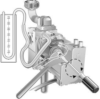
10 Setting gas pressures Setting the minimum and the maximum power of the boiler. Check that the supply pressure to the gas valve is a minimum of 20 mbar for natural gas. 2. To do this, remove the screw A. Fit the pipe of the pressure gauge to the pressure connection of the gas valve B. When you have completed this operation, replace the screw A securely into its housing to seal off the gas. 3. To check the pressure supplied by the gas valve to the burner, remove the screw C. Fit the pipe of the pressure gauge to the pressure outlet of the gas valve D. Disconnect the compensation pipe either from the gas valve or from the sealed chamber. 4. Set the On/Off button to position < I > and the "summer/winter" switch to the winter position. To set the maximum power, turn on the hot water tap and allow the hot water tap to run at a rate of about 8 litres/minute so that the main burner lights. Adjust nut E on the modureg to set the gas pressure (displayed on the pressure gauge) corresponding to the maximum power (see table A page ). 5. To set the minimum power, disconnect a supply terminal from the modureg and adjust screw F. Turn the screw clockwise to increase the pressure and counter-clockwise to decrease the pressure (displayed on the pressure gauge) corresponding to the minimum power (see table A page ). 6. When you have completed the above operations, turn off the hot water tap, re-connect the supply terminal to the modureg on the gas valve and replace the cap on the screw of the modureg. Setting the maximum heating circuit power 7. To set the maximum heating circuit power, place the On/Off button to position < I > and the "summer/winter" switch to winter position. Turn the knob of the heating thermostat clockwise to maximum; 8. Remove the left hand inspection panel of the P.C.B. and fit a small cross-head screwdriver in to the right hand potentiometer. Turn clockwise to increase the pressure or counter-clockwise to reduce the pressure. Adjust the setting to the required heating pressure value (displayed on the pressure gauge), as indicated in the diagrams shown in page. 9. Turn off the boiler by placing the main switch to the "Off" position. Setting pressure for soft ignition. Disconnect the detection electrode connection from the P.C.B. (see fig..3). Start the boiler and during the ignition sequence adjust the centre potentiometer until the gas pressure reads the required gas pressure as per the table below. Once the gas pressure is set turn off the boiler and reconnect the connection to the P.C.B. NB.: It may be necessary to reset the flame failure reset a number of times during this operation. NATURAL GAS (G20) BUTANE GAS (G30) PROPANE GAS (G3) Recommended pressure for slow ignition 5 mbar -.95 in w.g. 8 mbar in w.g. 9 mbar in w.g. 0 B029
11 Regulating the heating power for natural gas (G20) model 23 model 27 Regulating the heating power for butane gas (G30) model 23 model 27 Regulating the heating power for propane gas (G3) model 23 model 27 TABLE A GAS REQUIREMENTS NATURAL GAS (G20) BUTANE GAS (G30) PROPANE GAS (G3) Gas rate max 3.0 m3/h 06.0 ft 3/h Gas rate min.2 m /h 42.3 ft /h Inlet pressure 20 mbar 7.8 in w.g. Burner pressure max 2.3 mbar 4.8 in w.g m3/h 3. ft3/h 0.35 m /h 2.3 ft /h 28 mbar 0.9 in w.g. 28 mbar 0.9 in w.g..5 m 3 /h 40.6 ft 3 /h 0.46 m 3 /h 6.2 ft 3 /h 37 mbar 4.4 in w.g. 37 mbar 4.4 in w.g. Burner pressure min 2.0 mbar 0.8 in w.g. 5. mbar 2.0 in w.g. 7.0 mbar 2.7 in w.g. Burner injectors 3 x.25 3 x x 0.72 B029
. IMPORTANT!")


12 C C 0. Remove the pipe from the pressure gauge and connect screw C to the pressure outlet in order to seal off the gas.. Carefully check the pressure outlets for gas leaks (valve inlet and outlet). IMPORTANT! Whenever you disassemble and reassemble the gas connections, always check for leaks using a soap and water solution. Anti-cycling Device Soft-light Adjustment Max. Heating Adjustment Setting the anti-cycling device This appliance is equipped with a potentiometer which delays the ignition of the heating control and is situated on the P.C.B. (see the electrical diagrams). By adjusting the potentiometer, it is possible to change the time interval between the burner shutting down and its next ignition. It is preset at minute and can be adjusted from 0 to 2 minutes. Use this control in particular situations where continuous shutting down and ignition of the main burner occurs. Removing the spark generator (SIT Sigma gas valve) Q. Disconnect ignition leads Q by pulling upwards (see fig..27); 2. Remove the screws R (see fig..28) with a Pozidrive No. 2 star tip screwdriver; 3. Remove the spark generator. Fig..27 R Fig..28 Fig B029
.")
; 2.")
 with a Pozidrive No.")
13 Removing the spark generator (SIT Tandem gas valve). Disconnect ignition leads Q by pulling upwards (see fig..30); 2. Remove the screws R (see fig..3) with a Pozidrive No. 2 star tip screwdriver; 3. Remove the spark generator. Q Fig..30 R R Fig..3 Fig..32 B029 3

. Attention!")


14 Removing the gas valve. Disconnect all the cables from the solenoid and modureg; 2. Remove the spark generator; 3. Release the top nut S using a 30 mm open ended spanner (see fig..3); 4. Remove the screws T from the bottom of the gas valve pipe (see fig..32). Attention!! The gas valve is connected with the two pipes (as shown) with an O-ring connection. S T T Fig..33 Fig..34 Fig..35 Fig Access to the Hydraulic Circuits Important! Before any component is removed, the boiler must be drained of all water. U U Removing the D.H.W. (secondary) exchanger. Remove the screw U (see fig..37); 2. Push the exchanger towards the rear of the boiler, lift upwards and remove out of the front of the boiler; 3. Before replacing the exchanger ensure that the O-rings are in good condition and replace if necessary. Fig B029


; 3.")
15 Removing the safety valve. Loosen nut V (see fig..38); 2. Remove the valve. V Fig..38 Removing the automatic air vent. Unscrew valve W (see fig..39). W Fig..39 Removing the main circuit flow switch. Remove the cable of the main circuit flow switch Y ; 2. Remove the screws Y (see fig..40); 3. Remove the main circuit flow switch. Y Y Y Fig..40 B029 5

.")
; 2.")
; 3.")
16 Removing the pump. Unscrew Z and remove the electrical connection (see fig..4); 2. Release the nuts A and remove the pump (see fig..42). A Z A Fig..4 Fig..42 Removing the pressure gauge. Remove the inspection panel (see fig ); 2. Release coupling A2 using a 4 mm open ended spanner (see fig..43); 3. Push the pressure gauge through the control panel from the rear (see fig..44). A2 Fig..43 Fig B029
; 2.")
. A3 Fig..45 A4 Fig.")


.")
17 Removing the expansion vessel. Remove nut A3 away from the expansion vessel (see fig..45); 2. Remove nut A4 (see fig..46); 3. Remove expansion vessel (see fig..47). A3 Fig..45 A4 Fig..46 Fig..47 Removing the overheat thermostat. Remove the electrical connection from the overheat thermostat (see fig..48); 2. Then remove the thermostat from the pipe by releasing its securing clip. Fig..48 Removing the heating temperature sensor (N.T.C.). Remove the electrical connector by pulling off the thermostat connections and unscrewing the sensor probe with a 4 mm open ended spanner (see fig..49). Fig..49 B029 7
; 2.")

.")
18 .6 Access to the Control System Checking fuse. Remove the inspection panel (see fig ); 2. Remove fuse (see fig..50). Fig..50 Removing the time clock. Remove the inspection panel (see fig ); 2. Remove electrical connection of the clock A5 (see fig..5); 3. Unclip the clock from the panel and remove (see fig..52). A5 Fig..5 Fig B029
.")

; 6. Disconnect the connection cable A7 (see fig..54); 7.")
; 9.")
19 N.B. It is possible to by-pass the time clock in the event of failure by simply unplugging the electrical connection from the P.C.B. (see fig..48). This will revert control of the central heating to the room stat connection on the reverse of the control panel. A6 A6 Removing the P.C.B.s. Isolate electricity; 2. Remove the front cover of the boiler; 3. Remove the inspection panel (see fig..6-.7); 5. Remove the mounting screws A6 (see fig..53); 6. Disconnect the connection cable A7 (see fig..54); 7. To remove the 24V P.C.B.: remove the electrical plug connectors and screws A8 (see fig..55); 8. To remove the 240V P.C.B.: remove the electrical plug connectors and screws A9 (see fig..56); 9. Replace either P.C.B. in reverse order. A6 A6 Fig..53 A8 A9 A7 A7 A8 A9 Fig..54 Fig..55 Fig..56 B029 9
20 2. FAULT FINDING 2. Fault Finding Guide (Flow-chart) It is possible to detect and correct any defect by using the standard fault finding diagrams described in this chapter. Preliminary Checks Make sure that: ) There is sufficient water in the system 2) The gas is turned on 3) The electricity to the boiler is on Press the On / Off Button HAS THE LIGHT for THE POWER SUPPLY COME ON? ) Check thefuses 2) Check thepower supplycord, plug and outlet 3) Check/replace the power supply PCB SUMMER SETTING FOR THE OPERATING MODE WINTER IS HOT WATER BEING DEMANDED? FUME DISCHARGE TEST IS HOT WATER BEING DEMANDED? FOR BOILERS EQUIPPED WITH AN ELECTRONIC ANT-FREEZE SYSTEM: HAS THE SAFETY BEEN TRIGGERED TO ACTIVATE THE DEVICE? (T sensor <5 C) DO THE PROGRAMMING TIMERAND/OREXTERNAL THERMOSTAT NEED TO BE ACTIVATED A FOR BOILERS EQUIPPED WITH AN ELECTRONIC ANT-FREEZE SYSTEM: HAS THE SAFETY BEEN TRIGGERED TO ACTIVATE THE DEVICE? (T sensor <5 C) 20 B029
21 A DOES THE CIRCULATION PUMP COME ON? POWER TO THE PUMP? ) Check for air in the system 2) Check thepressureswitch for activating pump 3) Check/replace water gaugeand refill the thesystem properly ) Turn theboiler off and then back on again (safetyreset) DOES THE INSUFFICIENT WATER INDICATOR LIGHT COME ON? (within 40 sec.) ) Check to see if pump is stuck 2) Replacecirculation pump ) Check wiring 2) Check/replace wire to PCB 3) Replace power supply PCB 4) Replace control PCB 5) Check microswitch when hot water isrequested. B B029 2
22 B DOES THE FAN COME ON? BOILER SHUTDOWN? ) Reset the boiler C PUMP SAFETY DEVICE ACTIVATED? ) Check/replace differential pressure switch for pump 2) Check/replace wiring 3) Check/replace PCB wire 4) Check/replace power supply PCB 5) Check/replace control PCB INTERNAL SAFETY DEVICE FOR PCB ACTIVATED? ) Check/replace air pressure switch/wiring 2) Check whether reset button is stuck 3) Check/replace flame detection electrode IS THERE POWER TO THE FAN? ) Check/replace wiring 2) Check/replace PCB wire 3) Check/replace power supply PCB 4) Check/replace control PCB 5) Check/replace air pressure switch ) Replace fan 22 B029
23 C IS THE AIR PRESSURE SWITCH ACTIVATED? ARE THE FUMES DISCHARGED CORRECTLY? DOES THE BURNER LIGHT? ) Check flue discharge 2) Check venturi & small pipes 3) Check wire for air press.switch 4) Check/replace air press. switch 5) Check/replace PCB wire 6) Check/replace power PCB 7) Check/replace control PCB ) Check/replace igniter plugs 2) Check wiring 3) Check starter 4) Check small wire 5) Check power supply PCB 6) Check control PCB ) Check supply of gas to gas valve 2) Check power supply PCB 3) Check control PCB 4) Check functionality of the valve SAFETY SHUTDOWN OF THE BOILER ACTIVATED? ) Check whether flame detection electrode is hit by theflame 2) Check the electrode 3) Check the power PCB 4) Check the control PCB D WAS THE RESET SWITCH PRESSED? Shutdown LED off Restart of the fan B029 23
24 D IS THERE STILL A PROBLEM? FUNCTIONS RMALLY LIST OF MALFUNCTIONS Delivery of hot water for domestic use: when the tap is turned on, the burner goes out. Delivery of hot water for domestic use: the radiatores are heated in summer mode. Delivery of hot water for domestic use: water temperature is not satisfactory. Delivery of hot water for domestic use: noisy operation. POSSIBLE CAUSES - Air in the secondary exchanger - Hot water pressure switch is defective - 3-way valve is defective - 3-way valve is defective - Check heating sensors - Check gas settings and regulation - Check water flow rate - Check exchanger for domestic hot water - Primary exchanger is defective - Low water pressure in heating system - Check gas settings and regulation Drop/increase in pressure in primary circuit. Repeated shutdowns. Safety thermostat is triggered repeatedly. When the cold water tap is turned off, the boiler comes on. Temperature of radiators not satisfactory. - Check for leaks in heating circuit - Defective water supply inlet valve - Secondary exchanger is defective - Expansion vessal is empty - Detection electrodes are defective - Check gas settings and regulation - Check electrical circuit for flamedetection - Faulty (contacts) ntc heating sensors- - Defective (poorly calibrated) safety thermostat - Presence of air in the primary water circuit - Drop in pressure in the water mains, resulting in water hammering - Check ntc heating sensor - Check by-pass - Check gas settings and regulation 24 B029
25 2.2 Fault Finding Using the Total Check System Malfunction Signalling Boiler Off Auto diagnostic state Spark ignition state Boiler functioning normally Lockout Boiler thermostat satisfied Room thermostat/clock no demand or selector in summer setting A b C d E F G I m Faulty ventilation system Air pressure switch stuck in N.O. position Faulty reset switch Faulty main circuit flow switch Faulty flame detection Faulty overheat thermostat Faulty exhaust fumes sensor Faulty heating sensor (N.T.C.) Faulty D.H.W. sensor (N.T.C.) Pump fed Main flow switch closed Flame detected Air pressure switch N.O. Water at required temperature Room thermostat/clock no demand or selector in summer setting Auto diagnostics faulty D.H.W. exchanger efficiency control Heating circuit efficiency control Heating temperature control D.H.W. temperature control B029 25
26 3. ELECTRICAL DIAGRAMS Legend: AT = High Voltage P.C.B. BT = Low Voltage P.C.B. B = Flame Failure L.E.D. C = Insufficient Water Pressure L.E.D. D = Water Temperature Indicator L.E.D.s E = Overheat Thermostat Warning L.E.D. F = System Reset Button G = Selector Knob for Operating Mode H = Domestic Hot Water Temp. Adjustment I = Central Heating Temp. Adjustment J = Wire Connector for Room Thermostat K = Connector for Total Check System M = Anti-cycling Device Adjustment for Heating N = Soft-light Adjustment O = Max Heating Temperature Adjustment P = Time Clock Connection Q = On/Off L.E.D. R = On/Off Switch S = Interface Wire for P.C.B.s T = Relay Motorised Valve U = Ignitor Relay V = Gas Valve Relay W = Fan Relay X = Circulation Pump Relay Y = Selector TCS2 Aa = Adaptor (British Gas use only) A0 = A02 = A03 = A04 = A05 = A06 = A07 = A08 = A09 = A0 = A = A2 = B0 = B02 = B03 = B05 = B06 = B07 = B08 = Air Pressure Switch Fan Gas Valve Ignitor Motorised Valve Circulation Pump Flame Detector Earth Terminal Flame Detection Circuit Flame Indicator L.E.D. Transformer Filter Over Heat Thermostat Room Thermostat Gas Valve Modulator Heating Sensor Pressure Switch for Heating Circuit Microswitch for Diverter Valve Time Clock Colours Gry = Grey Rd = Red Bl = Blue Grn/Yll = Yellow/Green Wh = White Brn = Brown Blk = Black Wh/Rd = White/Red 26 B029
27 EX C-MI/FFI 8 A/23 MFFI - A/27 MFFI B029 27
28 4. SHORT SPARE PARTS LIST A/23 MFFI - A/27 MFFI (SIT Sigma Gas Valve) A 23/27 MFFI 28 B029
29 A/23 MFFI - A/27 MFFI (SIT Sigma Gas Valve) Key no AB 57CD AB 72CD AB 89CD AB 98CD A 20B 20C 20D 2AB 2CD G.C. part no E03 88 E E E Description Expansion vessel Gasket 3/4" Overheat thermostat Main flow Switch Temp probe (C.H.W.) Microswitch for 3-way/main flow group Gasket /2" Manual vent cock Safety valve 3 bar /2" Pressure gauge Time clock P.C.B. EX C-MI/FFI P.C.B. EI A-MFFI P.C.B. cable Fan Fan Fan inlet gasket Venturi (exhaust manifold/header) Air pressure switch Air pressure switch Fastening spring Automatic air release valve Gasket " O-ring Secondary exchanger (plate-type) exchanger 23kW Secondary exchanger (plate-type) exchanger 27kW O-ring (secondary exchanger) 20-8 O-ring Gasket 3/8" Pump Pump O-ring (3) Gasket Gas valve (SIT Sigma) Spark generator Detection electrode Gasket /4" Ignition electrode (R.H.) Ignition electrode (L.H.) Main burner Main burner Main burner Main burner Main exchanger Main exchanger Front panel runner kit D.H.W. actuator kit SIT Sigma gas valve operator coils Heating by-pass kit D.H.W. pressure switch kit 3-way spring kit D.H.W. diaphram valve Main flow switch diaphram Main flow switch magnet Main flow switch spring Main flow switch top cap Main flow switch reed system Burner jet.25 full kit (Natural gas) Burner jet 0.72 full kit (LPG) ARISTON Part No B029 29
30 A/23 MFFI - A/27 MFFI (SIT Tandem Gas Valve) Key no AB 57CD AB 72CD AB 89CD AB 98CD A 22B 22C 22D 23AB 23CD G.C. part no E03 88 E E E Description Expansion vessel Gasket 3/4" Overheat thermostat Main flow Switch Temp probe (C.H.W.) Microswitch for 3-way/main flow group Gasket /2" Manual vent cock Safety valve 3 bar /2" Pressure gauge Time clock P.C.B. EX C-MI/FFI P.C.B. EI A-MFFI P.C.B. cable Fan Fan Fan inlet gasket Venturi (exhaust manifold/header) Air pressure switch Air pressure switch Fastening spring Automatic air release valve Gasket " O-ring Secondary exchanger (plate-type) exchanger 23kW Secondary exchanger (plate-type) exchanger 27kW O-ring (secondary exchanger) O-ring (20-8) Gasket 3/8" Pump Pump Gas valve (SIT Tandem) Spark generator O-ring (3) Detection electrode Gasket /4" Ignition electrode (R.H.) Ignition electrode (L.H.) Main burner Main burner Main burner Main burner Main exchanger Main exchanger D.H.W. actuator kit SIT Tandem gas valve operator coils SIT Tandem modureg coil Gas modulator cartridge Heating by-pass kit D.H.W. pressure switch kit 3-way spring kit D.H.W. diaphram valve Main flow switch diaphram Main flow switch magnet Main flow switch spring Main flow switch top cap Main flow switch reed system Burner jet.25 full kit (Natural gas) Burner jet 0.72 full kit (LPG) ARISTON Part No B029
31 A 23/27 MFFI (SIT Tandem Gas Valve) Key no AB 57CD AB 72CD AB 89CD AB 98CD A 22B 22C 22D 23AB 23CD G.C. part no E03 88 E E E Description Expansion vessel Gasket 3/4" Overheat thermostat Main flow Switch Temp probe (C.H.W.) Microswitch for 3-way/main flow group Gasket /2" Manual vent cock Safety valve 3 bar /2" Pressure gauge Time clock P.C.B. EX C-MI/FFI P.C.B. EI A-MFFI P.C.B. cable Fan Fan Fan inlet gasket Venturi (exhaust manifold/header) Air pressure switch Air pressure switch Fastening spring Automatic air release valve Gasket " O-ring Secondary exchanger (plate-type) exchanger 23kW Secondary exchanger (plate-type) exchanger 27kW O-ring (secondary exchanger) O-ring (20-8) Gasket 3/8" Pump Pump Gas valve (SIT Tandem) Spark generator O-ring (3) Detection electrode Gasket /4" Ignition electrode (R.H.) Ignition electrode (L.H.) Main burner Main burner Main burner Main burner Main exchanger Main exchanger D.H.W. actuator kit SIT Tandem gas valve operator coils SIT Tandem modureg coil Gas modulator cartridge Heating by-pass kit D.H.W. pressure switch kit 3-way spring kit D.H.W. diaphram valve Main flow switch diaphram Main flow switch magnet Main flow switch spring Main flow switch top cap Main flow switch reed system Burner jet.25 full kit (Natural gas) Burner jet 0.72 full kit (LPG) ARISTON Part No B029 3
32 Manufacturer: Merloni TermoSanitari SpA - Italy Commercial subsidiary: MTS (GB) LIMITED MTS Building Hughenden Avenue, High Wycombe Bucks HP3 5FT Telephone: (0494) Fax: (0494) Technical Service Hotline: (0494) B029 Stampa BIEFFE Recanati
Servicing Instructions Type C Boilers G.C.N: LEAVE THESE INSTRUCTIONS ADJACENT TO THE GAS METER
 Servicing Instructions Type C Boilers G.C.N: 4-6-0 47-6-08 47-6-09 47-6-3 LEAVE THESE INSTRUCTIONS ADJACENT TO THE GAS METER TABLE OF CONTENTS Page No.. SERVICING INSTRUCTIONS. Replacement of Parts 3.2
 A/23 MFFI - A/27 MFFI G.C.N. 47-6-0 / 47-6-2 Installation Instructions Type C Boilers LEAVE THESE INSTRUCTIONS ADJACENT TO THE GAS METER Country of destination: GB TABLE OF CONTENTS. GENERAL INFORMATION.
MAINTENANCE AND SERVICE GUIDE
 c Dimensions MAINTENANCE AND SERVICE GUIDE System II 80 and 100 Central Heating Fanned Flue Boiler Sizes in mm Flue types: C 12 or 42: horizontal C 32 xx: vertical concentric C 32 xy: Twin flue Boiler
The guarantee on this appliance is valid for 12 months from the first day of installation.
 Users Manual Dear Customer, Thank you for choosing an ARISTON boiler. We guarantee that your boiler is a reliable and technically sound product. This Users Manual provides detailed instructions and recommendations
Installation Instructions Type C Boilers G.C.N: LEAVE THESE INSTRUCTIONS ADJACENT TO THE GAS METER
 Installation Instructions Type C Boilers G.C.N: 4-6-0 47-6-08 47-6-09 47-6-3 LEAVE THESE INSTRUCTIONS ADJACENT TO THE GAS METER Country of destination: GB TABLE OF CONTENTS. GENERAL INFORMATION. General
Mikrofill Ethos Condensing combination boiler. Maintenance Instructions 24cc
 Mikrofill Ethos Condensing combination boiler Maintenance Instructions 24cc IMPORTANT Benchmark Installation, Commissioning and Service Record Log Book is enclosed in your customer information pack. This
Service manual. Riva Plus HE. M296.28SR/C System boiler. Wall hung, fanflue, roomsealed, high efficiency gas boiler
 Wall hung, fanflue, roomsealed, high efficiency gas boiler Service manual Riva Plus HE Models G.C. ppl. No. M296.24SR/C 41-583-18 System boiler M296.28SR/C 41-583-19 System boiler Leave this manual adjacent
SPARE PARTS EXPLODED VIEW GAS WALL BOILERS Model MICROGENUS PLUS. R EN - Edition 02-01/04/2007
 SPARE PARTS EXPLODED VIEW GAS WALL BOILERS Model MICROGENUS PLUS R8215343-02EN - Edition 02-01/04/2007 Domestic Gas Boilers MICROGENUS PLUS 537814 MICROGENUS PLUS 24 MET...... 3300078 MICROGENUS PLUS 21
Service manual GARDA HE MK2. M96A.24SM/B Combi boiler M96A.28SM/B Combi boiler
 Wall hung, fan flue, room sealed, high efficiency gas boiler Service manual GRD HE MK2 Models: G.C. ppl. No. M96.24SM/ 47---583---15 Combi boiler M96.28SM/ 47---583---16 Combi boiler Leave this manual
Installation Instructions Type C Boilers G.C.N:
 Installation Instructions Type C Boilers G.C.N: 47-6- LEAVE THESE INSTRUCTIONS WITH THE END USER 400 Country of destination: GB TABLE OF CONTENTS. GENERAL INFORMATION. General Instructions.2 Overall View
SERVICE MANUAL RIVA COMPACT M90E.24S M90E.28S M90E.32S Wall hung, fan flue, room sealed gas boiler
 Wall hung, fan flue, room sealed gas boiler SERVICE MNUL RIV COMPCT Models: G.C. ppl. No. M90E.24S 47--970--17 M90E.28S 47--970--18 M90E.32S 47--970--21 Leave this manual adjacent to the gas meter iasi
TABLE OF CONTENTS. IMPORTANT Please read this manual carefully.
 User s Manual TABLE OF CONTENTS 1) GENERAL INFORMATION page 5 2) OPERATING INSTRUCTIONS page 8 3) TIME CLOCK page 11 4) USEFUL INFORMATION AND TROUBLESHOOTING page 13 B003 IMPORTANT Please read this manual
SIME FORMAT WALL HUNG BOILERS MODEL 34i AND MODEL 34e. cod A
 cod. 6272262A GENERAL DATA Heating Data Heat Output Input (Adjustable) (Adjustable) Format 34i 11.2 34KW 45 145MJ/hr Format 34e 11.2 34KW 45 145MJ/hr General Specifications FORMAT 34i 34e Main burner injectors
HEAT ONLY & COMBI BOILER
 Spare Parts Catalog Riva Plus HEAT ONLY & COMBI BOILER M135.30 CM / M135.30 CR Prepared by: QHT, Inc. Portsmouth, NH 603-334-6400 phone www.qhtinc.com Rev: 06.23.09 1 06/09 2 06/09 TABLE OF CONTENTS Description
DOMESTIC HOT WATER Follow operational sequence
 DOMESTIC HOT WATER Follow operational sequence Turn Winter/Summer selector to Summer position. The display is switch on. Go to section A Error 110 flashing Error 131 flashing Turn the selector to reset
ATMOSPHERIC GAS BOILER INSTALLATION, OPERATING AND MAINTENANCE MANUAL
 STREBEL GENEVA CE ATMOSPHERIC GAS BOILER INSTALLATION, OPERATING AND MAINTENANCE MANUAL INDEX TABLE 1 TECHNICAL DATA SECTION 1 SECTION 2 SECTION 3 SECTION 4 SECTION 5 SECTION 6 SECTION 7 SECTION 8 SECTION
AUS. Format 34I-34E BF
 AUS Format 34I-34E BF Installation and servicing instructions CONTENTS 1 TECHNICAL FEATURES AND DIMENSIONS..................................................... 2 2 GENERAL REQUIREMENTS FOR INSTALLATION.................................................
Service manual RIVA COMPACT HE M96.24SM/C M96.28SM/C M96.32SM/C M96.24SR/C2 M96.28SR/C
 Wall hung, fan flue, room sealed, high efficiency gas boiler Service manual RIV COMPCT HE Models: G.C. ppl. No. M96.24SM/C2 47---583---05 M96.28SM/C2 47---583---06 M96.32SM/C2 47---583---07 M96.24SR/C2
SERVICE MANUAL RIVA PLUS M90D.24S M90D.28S M90D.24SR M90D.28SR
 Wall hung, fan flue, room sealed gas boiler SERVICE MANUAL RIVA PLUS Models: G.C. Appl. No. M90D.24S 47--970--15 M90D.28S 47--970--16 M90D.24SR 41--970--08 M90D.28SR 41--970--09 Leave this manual adjacent
Service manual. Riva Plus HE. M296.28SM/C Combi boiler. Wall hung, fanflue, roomsealed, high efficiency gas boiler
 Wall hung, fanflue, roomsealed, high efficiency gas boiler Service manual Riva Plus HE Models G.C. ppl. No. M296.24SM/C 47-583-24 Combi boiler M296.28SM/C 47-583-25 Combi boiler Leave this manual adjacent
Service manual. Riva Plus HE ERP. Wall hung, fanflue, roomsealed, high efficiency gas boiler. Leave this manual adjacent to the gas meter
 Wall hung, fanflue, roomsealed, high efficiency gas boiler Service manual Riva Plus HE ERP Models RIV PLUS HE 24S ERP RIV PLUS HE 28S ERP G.C. ppl. No. 41-583-31 SYSTEM BOILER 41-583-32 SYSTEM BOILER Leave
Wall hung combination boilers. This is a CAT II2H3+ appliance USER, INSTALLATION AND SERVICING INSTRUCTIONS SUPPORTED BY
 Wall hung combination boilers This is a CAT II2H3+ appliance SUPPORTED BY USER, INSTALLATION AND SERVICING INSTRUCTIONS Index Introduction... 3 User instructions...3 Introduction... 4 Controls and lighting...
Installation Instructions Type C Boilers G.C.N: LEAVE THESE INSTRUCTIONS WITH THE END-USER
 Installation Instructions Type C Boilers G.C.N: 47-116-14 47-116-15 LEAVE THESE INSTRUCTIONS WITH THE END-USER Country of destination: GB TABLE OF CONTENTS 1. GENERAL INFORMATION 1.1 GENERAL INSTRUCTIONS
Installation Instructions Type C Boilers G.C.N:
 Installation Instructions Type C Boilers G.C.N: 47-116-16 LEAVE THESE INSTRUCTIONS WITH THE END-USER Country of destination: GB TABLE OF CONTENTS 1. GENERAL INFORMATION 1.1 GENERAL INSTRUCTIONS 1.2 OVERALL
MAINTENANCE AND SERVICE GUIDE
 c MAINTENANCE AND SERVICE GUIDE Fanned Flue Condensing Central Heating System Boiler 24 and 30 Dimensions Outer case dimensions : - Width : 440 (minimum space required 450) - Height : 850 - Depth : 380
Service manual RIVA ADVANCE HE M110.24SM/C M110.32SM/C Wall hung, fan flue, room sealed, high efficiency gas boiler
 Wall hung, fan flue, room sealed, high efficiency gas boiler Service manual RIV DVNCE HE Models: G.C. ppl. No. M110.24SM/C 47---970---29 M110.32SM/C 47---970---30 Leave this manual adjacent to the gas
Service manual GARDA HE GARDA HE SILVER M96.24SM/B M96.28SM/B M96.24SM/D M96.28SM/D
 Wall hung, fan flue, room sealed, high efficiency gas boiler Service manual GRD HE Models: G.C. ppl. No. M96.24SM/B 47---970---25 M96.28SM/B 47---970---26 GRD HE SILVER Models: G.C. ppl. No. M96.24SM/D
INSTALLATION AND MANINTENANCE INSTRUCTIONS
 INSTALLATION AND MANINTENANCE INSTRUCTIONS Appr. Nr. A 9503 T - 0085 AQ 0765 PEGASUS F2 T HIGH EFFICIENCY GAS-FIRED CAST-IRON BOILERS Models 51-68 - 85-102 2 Contents 1. General technical data 2. Dimensional
BG2000S PRE-MIX GAS BURNER
 BG000S PRE-MIX GAS BURNER INSTALLATION OPERATION & MAINTENANCE DOCUMENTATION STOKVIS ENERGY SYSTEMS 96R WALTON ROAD EAST MOLESEY SURREY KT8 0DL TEL: 08707 707 77 FAX: 08707 707 767 E-MAIL:info@stokvisboilers.com
12.0 Servicing. Electrode Position Fig Annual Servicing Inspection (Cont) 4 ±0.5
 4 ±0.5") 4 ±0.5 12.0 Servicing 12.2 Annual Servicing Inspection (Cont) Flame Sensing 5 ±1 10 ±1 Position Fig. 45 Spark Ignition 5. Remove the clip securing the gas feed pipe to the air/gas venturi. Disconnect the
4 ±0.5 12.0 Servicing 12.2 Annual Servicing Inspection (Cont) Flame Sensing 5 ±1 10 ±1 Position Fig. 45 Spark Ignition 5. Remove the clip securing the gas feed pipe to the air/gas venturi. Disconnect the
SPARE PARTS EXPLODED VIEW GAS WALL BOILERS Model EGIS - AS. R EN - Edition 03-01/03/2008
 SPARE PARTS EXPLODED VIEW GAS WALL BOILERS Model R8215807-03EN - Edition 03-01/03/2008 3300252 EGIS 24 FF NG (IT)...... 3300179 EGIS 24 FF N...... 3300193 EGIS 24 FF NG (EAA1)...... 3300195 EGIS 24 FF
MAINTENANCE AND SERVICE GUIDE
 C Dimensions MAINTENANCE AND SERVICE GUIDE Fanned Flue Condensing Combination Boiler Heating and Storage Domestic Hot Water Outer case dimensions : - Width : 440 (minimum space required 450) - Height :
SPARE PARTS EXPLODED VIEW GAS WALL BOILERS Model CLAS. R EN - Edition 01-01/02/2007
 SPARE PARTS EXPLODED VIEW GAS WALL BOILERS Model CLAS R8215828-01EN - Edition 01-01/02/2007 3300187 CLAS 24 NG (EAA1)...... 3300189 CLAS 24 CF NG (EAA1)...... 3300188 CLAS 28 NG (EAA1)...... Reference
End User Manual ACO 35 MFFI COMBI
 End User Manual AO 35 MFFI OMBI ountry of destination: GB/IE Dear ustomer, Thank you for choosing an ARISTON boiler. We guarantee that your boiler is a reliable and technically sound product. This manual
NIKE Star 24 3 E. Instantaneous wall-hung with open chamber boilers. NIKE Star 24 3 E
 Instantaneous wall-hung with open chamber boilers Small wall-mounted open chamber, conventional flue instant boiler. General features. is a wall-mounted, open combustion chamber, conventional flue generator
microgenus II 24 MFFI microgenus II 28 MFFI microgenus II 31 MFFI Installation and Servicing Instructions Type C Boilers
 2 5 6 2 5 6 microgenus II 24 MFFI microgenus II 28 MFFI microgenus II 3 MFFI Installation and Servicing Instructions Type C Boilers G.C.N: 47-6-25 (24kW) G.C.N: 47-6-26 (28kW) G.C.N: 47-6-27 (3kW) LEAVE
JANUS 3 CIRCULATOR WATER HEATER INSTALLATION, COMMISSIONING & SERVICING INSTRUCTIONS G.C. No
 JANUS 3 CIRCULATOR WATER HEATER INSTALLATION, COMMISSIONING & SERVICING INSTRUCTIONS G.C. No 53 416 06 Publication No. ZZ 180/17 May 2000 These appliances are tested and certified by B G Technology for
INSTALLATION, OPERATING AND SERVICING INSTRUCTIONS BG 2000-S (V13) RU PL DE IT ES NL EN 1 662Y0600 A
 RU PL DE IT ES NL EN 1 662Y0600 A") INSTALLATION, OPERATING AND SERVICING INSTRUCTIONS G 2000-S 25-35 - 45-55 60-70 - 100 (V13) 1 Index WARNINGS GAS FLOW RATE DIMSIONS SETTINGS PARAMETERS SERVICING THE URNER 3 8 13 OPERATING DESCRIPTION
INSTALLATION, OPERATING AND SERVICING INSTRUCTIONS G 2000-S 25-35 - 45-55 60-70 - 100 (V13) 1 Index WARNINGS GAS FLOW RATE DIMSIONS SETTINGS PARAMETERS SERVICING THE URNER 3 8 13 OPERATING DESCRIPTION
BOSCH CONDENS 5000W ZSB18-2A
 6720646195-00.1Wo HYDRONIC GAS SYSTEM BOILER 18kW BOSCH CONDENS 5000W ZSB18-2A Installation and Servicing Instructions 10 Boiler information AU/NZ 1 2 3 4 5 15 6 14 7 8 6720644743-04.1Wo 13 12 11 10 9
Baxi Maxflow Combi WM
 Baxi Maxflow Combi WM Gas Fired Wall Mounted Combination Boiler with Unvented Hot Water Storage Please keep these instructions safe. Should you move house, please hand them over to the next occupier. User
User Manual FLOWMAX-90. for model. Condensing water heater 85,000 BTU. Installation, operating, commissioning and maintenance instructions.
 User Manual for model FLOWMAX-90 Condensing water heater 85,000 BTU WARNING If the information in these instructions is not followed exactly, a fire or explosion may result, causing property damage, personal
AMBIRAD VISION VS RANGE RADIANT TUBE HEATERS SERVICING & COMMISSIONING MANUAL
 Instruction Manual. AMBIRAD VISION VS RANGE RADIANT TUBE HEATERS SERVICING & COMMISSIONING MANUAL Note: For use with all Vision VS models with Generation codes AA & AB. (also for burners fitted with SIT
Aqua Balance. AquaBalance TM CONTROL MODULE QUICK START GUIDE LEGEND
 Aqua Balance AquaBalance TM CONTROL MODULE QUICK START GUIDE 10 1 Domestic Hot Water temperature setpoint decreasing button 2 Domestic Hot Water temperature setpoint increasing button 3 Central Heating
SERIES. End User Manual ACO 27 MFFI G.C.N: ACO 32 MFFI G.C.N: ACO 27 RFFI G.C.N: ACO 32 RFFI G.C.
 SERIES End User Manual AO 27 MFFI G..N: 47-116-34 AO 32 MFFI G..N: 47-116-35 AO 27 RFFI G..N: 41-116-09 AO 32 RFFI G..N: 41-116-10 LEAVE THESE INSTRUTIONS WITH THE END USER ountry of destination: GB/IE
AMBIRAD VISION VS RANGE RADIANT TUBE HEATERS SERVICING & COMMISSIONING MANUAL
 Instruction Manual. AMBIRAD VISION VS RANGE RADIANT TUBE HEATERS SERVICING & COMMISSIONING MANUAL Note: For use with all Vision VS models with Generation codes AA, AB & AC. (also for burners fitted with
TC MODULE (FFD) (with Gas Hob)
 (with Gas Hob)") TC MODULE (FFD) (with Gas Hob) Installation Instructions REMEMBER: when replacing a part on this appliance, use only spare parts that you can be assured conform to the safety and performance specification
TC MODULE (FFD) (with Gas Hob) Installation Instructions REMEMBER: when replacing a part on this appliance, use only spare parts that you can be assured conform to the safety and performance specification
Baxi Maxflow Combi FS
 Baxi Maxflow Combi FS Gas Fired Floor Standing Combination Boiler with Unvented Hot Water Storage Please keep these instructions safe. Should you move house, please hand them over to the next occupier.
Servicing manual. Wall-mounted condensing gas boiler 600 Series - 11S / 19S / 24S / 24C /2002 GB(EN) For trade use
 For trade use") GB122 7210 1300-12/2002 GB(EN) For trade use Servicing manual Wall-mounted condensing gas boiler 600 Series - 11S / 19S / 24S / 24C Please read thoroughly before attempting to diagnose fault List of contents
GB122 7210 1300-12/2002 GB(EN) For trade use Servicing manual Wall-mounted condensing gas boiler 600 Series - 11S / 19S / 24S / 24C Please read thoroughly before attempting to diagnose fault List of contents
Servicing manual. 600 Series - 11S / 19S / 24S / 24C. Wall-mounted condensing gas boiler. For trade use
 GB122 Servicing manual Wall-mounted condensing gas boiler 600 Series - 11S / 19S / 24S / 24C For trade use Please read thoroughly before attemting to diagnose fault 7217 4900 (03/2010) GB/IE List of contents
Mikrofill Ethos Condensing combination boiler
 Mikrofill Ethos Condensing combination boiler User Instructions 24cc CE Mark Mikrofill gas appliances comply with the requirements contained in CE Mark documents contained with European directives applicable
Technical Documentation
 Technical Documentation FEB-20E 09-2003 TECHNICAL DATA Model Category FEB-20E II 2H3P Type C 12,C 32,C 42,C 52 Maximum kw 23,8 Central Heating (C.H) Output Output kcal/h 20.468 Minimum kw 9,3 Output kcal/h
Service manual RIVA ADVANCE HE M110B.24SM/C M110B.32SM/C M110B.24SR/C
 Wall hung, fanflue, roomsealed, high efficiency gas boiler Service manual RIV DVNCE HE Models G.C. ppl. No. M110B.24SM/C 47---583---11 M110B.32SM/C 47---583---12 M110B.24SR/C 41---583---07 Leave this manual
chaffoteaux ltd. CORVECELT TS CONFORMS WITH EUROPEAN (BS5386Ptl) EN26 installation servicing requirements
 EN26 installation servicing requirements") chaffoteaux ltd. CORVECELT TS CONFORMS WITH EUROPEAN (BS5386Ptl) STANDARD EN26 installation servicing requirements contents Page 3 : TECHNICAL DATA Pages 4 and 5 : INSTALLATION Pages 6 and 7 : SERVICING
chaffoteaux ltd. CORVECELT TS CONFORMS WITH EUROPEAN (BS5386Ptl) STANDARD EN26 installation servicing requirements contents Page 3 : TECHNICAL DATA Pages 4 and 5 : INSTALLATION Pages 6 and 7 : SERVICING
GB24 & GB30. User Manual
 GB24 & GB30 User Manual BOILER OUTPUT To Domestic Hot Water:To Central Heating: GB24/30 Minimum 8.0 kw (27,296 Btu/h) GB24 Maximum 24.2 kw (82,570 Btu/h) GB30 Maximum 30.3 kw (103,384 Btu/h) GB24/30 Minimum
Logic+ Combi
 USER GUIDE Logic+ Combi 24 30 35 When replacing any part on this appliance, use only spare parts that you can be assured conform to the safety and performance specification that we require. Do not use
Bosch Group. 15SBi / 24SBi. WALL MOUNTED BOILERS FOR CENTRAL HEATING and Indirect supply of domestic hot water
 Bosch Group 15SBi / 24SBi WALL MOUNTED BOILERS FOR CENTRAL HEATING and Indirect supply of domestic hot water INSTALLATION AND SERVICING INSTRUCTIONS 24SBi This appliance is for use with Natural Gas or
E-COMBI EVO E-SYSTEM EVO
 E-COMBI EVO E-SYSTEM EVO User s manual CONDENSING WALL-HUNG GAS BOILER G.C.N.:47-116-68 (24 kw) G.C.N.:47-116-69 (30 kw) G.C.N.:47-116-70 (38 kw) G.C.N.:41-116-39 (24 kw) G.C.N.:41-116-40 (30 kw) Country
Condensing. Installation Instructions Type C Boilers G.C.N: LEAVE THESE INSTRUCTIONS WITH THE END-USER
 Installation Instructions Type C Boilers G.C.N: 41-116-03 47-116-17 LEAVE THESE INSTRUCTIONS WITH THE END-USER Condensing Country of destination: GB 275 TABLE OF CONTENTS 1. GENERAL INFORMATION 1.1. GENERAL
USERS GUIDE. LOGIC+ Combi 24, 30, 35
 USERS GUIDE LOGIC+ Combi 24, 30, 35 When replacing any part on this appliance, use only spare parts that you can be assured conform to the safety and performance specification that we require. Do not use
Service manual. Riva Plus HE ERP RIVA PLUS HE 24C ERP COMBI BOILER RIVA PLUS HE 28C ERP COMBI BOILER
 Wall hung, fanflue, roomsealed, high efficiency gas boiler Service manual Riva Plus HE ERP Models G.C. ppl. No. RIV PLUS HE 24C ERP 47-583-41 COMI OILER RIV PLUS HE 28C ERP 47-583-42 COMI OILER Leave this
CBX 24, 32 & 38 SBX 30
 751030 MANUAL (NEW) 21/9/10 08:39 Page 1 Eden X Type CBX 24, 32 & 38 SBX 30 INSTALLATION AND SERVICING INSTRUCTIONS TO BE GIVEN TO THE USER 0086 EC 87/BP/35 G.C. Appliance No. 47-260-05 (Eden CBX 24) G.C.
CELT STAR C GAS-FIRED WATER HEATER. Category: I 2E+ Installation and Use Instructions. Contents : Description:
 GAS-FIRED WATER HEATER Category: I 2E+ Installation and Use Instructions CELT STAR C These installation and User instructions are intended for appliances installed in Great Britain. This appliance, intended
PLEASE LEAVE THIS INSTRUCTION WITH THE USER. Ecomfort 30 HE. User instructions
 GB PLEASE LEAVE THIS INSTRUCTION WITH THE USER Ecomfort 30 HE User instructions CONTENTS OPERATING INSTRUCTIONS FOR THE USER 1.1 INTRODUCTION.................................................................................
SERIES. Installation and Servicing Instructions Type C Boilers G.C.N: LEAVE THESE INSTRUCTIONS WITH THE END-USER
 SERIES Installation and Servicing Instructions Type C Boilers G.C.N: 47-6-23 4-6-08 LEAVE THESE INSTRUCTIONS WITH THE END-USER Country of destination: GB TABLE OF CONTENTS. GENERAL INFORMATION.. GENERAL
Open Vented Condensing Boilers
 Dimplex 18 OV Dimplex 32 OV Open Vented Condensing Boilers User s Operating Instructions These instructions should be left with the user Dimplex Boilers 2008 CONTENTS SECTION DESCRIPTION PAGE 1.0 Using
Supplied by HeatingSpares247.com
 Users Guide Installation and Servicing Instructions G.C. Number 47-6-30 G.C. Number 47-6-3 Manufacturered by Merloni TermoSanitari spa - Italy Country of destination: GB - IE TABLE OF CONTENTS USERS GUIDE.
Bosch Group. 15SBi / 24SBi. WALL MOUNTED BOILERS FOR CENTRAL HEATING and Indirect supply of domestic hot water
 Bosch Group SBi / SBi WALL MOUNTED BOILERS FOR CENTRAL HEATING and Indirect supply of domestic hot water INSTALLATION AND SERVICING INSTRUCTIONS SBi This appliance is for use with Natural Gas or LPG (Cat
Installation and Servicing Instructions. Alpha 240/280. Range of Wall Mounted, Fan Assisted, Room Sealed, Gas Fired Combination Boilers
 Installation and Servicing Instructions Alpha 240/280 Range of Wall Mounted, Fan Assisted, Room Sealed, Gas Fired Combination Boilers For Technical help or for Service call... ALPHA HELPLINE Tel: (0322)
Baxi Bahama 100. Gas Fired Wall Mounted Combination Boiler. User s Operating Instructions
 Baxi Bahama 100 Please keep these instructions safe. Should you move house, please hand them over to the next occupier. Gas Fired Wall Mounted Combination Boiler User s Operating Instructions Natural Gas
Bosch Group. 35CDi WALL MOUNTED COMBINATION BOILER FOR CENTRAL HEATING AND MAINS FED DOMESTIC HOT WATER INSTALLATION AND SERVICING INSTRUCTIONS.
 Bosch Group CDi WALL MOUNTED COMBINATION BOILER FOR CENTRAL HEATING AND MAINS FED DOMESTIC HOT WATER INSTALLATION AND SERVICING INSTRUCTIONS CDi This appliance is for use with Natural Gas or LPG (Cat II
1 VICTRIX ZEUS Superior kw I features
 Wall-hung condensing VICTRIX ZEUS Superior kw I is the new range of wall-hung condensing boilers with 54 litre stainless steel storage tank available in two versions with nominal heat output of 26 kw and
kw Btu/h Metres Feet l/min. Gal/min C C
 80ic RSF WALL MOUNTED COMBINATION BOILER FOR CENTRAL HEATING AND MAINS FED DOMESTIC HOT WATER INSTALLATION AND SERVICING INSTRUCTIONS 6 720 605 553 PT 2000 11 Cat: II 2H3+ GC NUMBER NG: 47 311 43 LPG:
Gas Instantaneous Water Heater
 6 720 607 823 GB (06.06) SM Installation and Operating Instructions Gas Instantaneous Water Heater WR10..B... WR11..B... With electronic ignition and triple safety system consisting of ionisation detector,
MICROGENUS HE WALL-HUNG HIGH EFFICIENCY GAS COMBINATION BOILER. minimum space HIGH EFFICIENCY
 MICROGENUS HE WALL-HUNG HIGH EFFICIENCY GAS COMBINATION BOILER minimum space HIGH EFFICIENCY Compact, performance and reliability? Ariston in the UK Ariston is one of the main brands of the MTS Group,
400GL PX (PF) Servicing Instructions. For use in GB and IE PLEASE READ THESE INSTRUCTIONS BEFORE SERVICING THIS APPLIANCE
 Servicing Instructions. For use in GB and IE PLEASE READ THESE INSTRUCTIONS BEFORE SERVICING THIS APPLIANCE") Servicing Instructions 400GL PX (PF) For use in GB and IE DESN 512548 A Remember, when replacing a part on this appliance, use only spare parts that you can be assured conform to the safety and performance
Servicing Instructions 400GL PX (PF) For use in GB and IE DESN 512548 A Remember, when replacing a part on this appliance, use only spare parts that you can be assured conform to the safety and performance
PLEASE LEAVE THIS INSTRUCTION WITH THE USER ECOMFORT PLUS 25 HE. User instructions
 GB PLEASE LEAVE THIS INSTRUCTION WH THE USER ECOMFORT PLUS 25 HE User instructions All descriptions and illustrations provided in this manual have been carefully prepared but we reserve the right to make
GAS GRIDDLE INSTRUCTIONS MODEL: PGG6 MODEL: PGG7
 Page 1 of 17 GAS GRIDDLE INSTRUCTIONS MODEL: PGG6 MODEL: PGG7 SAFETY INSTRUCTIONS INSTALLATION INSTRUCTIONS OPERATION INSTRUCTIONS MAINTENANCE INSTRUCTIONS CONVERSION INSTRUCTIONS TECHNICAL DATA PARTS
User's Instructions. Alpha CD24C/32C. Range of Wall Mounted, Fan Assisted, Room Sealed, Gas Fired, High Efficiency Condensing Combination Boilers
 User's Instructions Alpha CD24C/32C Range of Wall Mounted, Fan Assisted, Room Sealed, Gas Fired, High Efficiency Condensing Combination Boilers For Technical help or for Service call... ALPHA HELPLINE
Performa 24. Gas Fired Wall Mounted Combination Boiler. User s Operating Instructions
 Performa Gas Fired Wall Mounted Combination Boiler User s Operating Instructions Please keep these instructions safe. Should you move house, please hand them over to the next occupier. Natural Gas Potterton
Baxi System 100 HE Plus. User s Operating Instructions. Wall Mounted Powered Flue Condensing Gas Fired Central Heating Boiler
 User s Operating Instructions Baxi System 100 HE Plus Wall Mounted Powered Flue Condensing Gas Fired Central Heating Boiler Please keep these instructions safe. Should you move house, please hand them
Heating Equipment. gas boilers RX GB. installation and servicing instructions
 Heating Equipment gas boilers RX GB installation and servicing instructions CONTENTS 1 TECHNICAL FEATURES AND DIMENSIONS 1.1 BOILER DESCRIPTION.............................................. page 1 1.2
Osprey 2 CFL
 Osprey 2 CFL 125-150 - 180-220 Gas Fired Floor Standing Boiler Installation and Servicing Instructions Please leave these instructions with the user Natural Gas Potterton Osprey 2 CFL 125 G.C.N o 41 590
SATK50-60 series CONTENTS. Recess Mounted Heat Interface Unit - SATK series INSTRUCTIONS FOR INSTALLATION, COMMISSIONING AND MAINTENANCE
 780EN www.caleffi.com Recess Mounted Heat Interface Unit - SATK series SATK0-60 series INSTRUCTIS FOR INSTALLATI, COMMISSIING AND MAINTENANCE Function The SATK series HIU allows independent control of
TECHNICAL INSTRUCTIONS
 TECHNICAL INSTRUCTIONS Benchmark 3.0LN 24-Month Maintenance Kit# 58015-04 This kit applies to units with an Ignitor and a separate gas injector. For units with an Ignitor-Injector (P/N 58023), see Kit
USER GUIDE VOGUE COMBI GEN2 C26 C32 C40
 USER GUIDE VOGUE COMBI GEN2 C26 C32 C40 When replacing any part on this appliance, use only spare parts that you can be assured conform to the safety and performance specification that we require. Do not
USERS GUIDE. Esprit eco 24, 30. For installation guide see reverse of book
 USERS GUIDE Esprit eco 24, 30 For installation guide see reverse of book When replacing any part on this appliance, use only spare parts that you can be assured conform to the safety and performance specification
North America SPARE PARTS CATALOGUE. - March
 North America SPARE PARTS CATALOGUE - March 2014 - HOW TO READ THE SPARE PARTS CATALOGUE In the spare part catalogue, after the exploded diagrams, there are the components lists of the boilers; this is
User's Instructions. Alpha CD25X/28X. Range of Wall Mounted, Fan Assisted, Room Sealed, Gas Fired, High Efficiency Condensing Combination Boilers
 User's Instructions Alpha CD5X/8X Range of Wall Mounted, Fan Assisted, Room Sealed, Gas Fired, High Efficiency Condensing Combination Boilers For Technical help or for Service call... ALPHA HELPLINE Tel:
400G/L PX (CF) Servicing Instructions. For use in GB and IE PLEASE READ THESE INSTRUCTIONS BEFORE SERVICING THIS APPLIANCE
 Servicing Instructions. For use in GB and IE PLEASE READ THESE INSTRUCTIONS BEFORE SERVICING THIS APPLIANCE") Servicing Instructions 400G/L PX (CF) For use in GB and IE DESN 511420 C Remember, when replacing a part on this appliance, use only spare parts that you can be assured conform to the safety and performance
Servicing Instructions 400G/L PX (CF) For use in GB and IE DESN 511420 C Remember, when replacing a part on this appliance, use only spare parts that you can be assured conform to the safety and performance
USER GUIDE VOGUE MAX SYSTEM
 USER GUIDE VOGUE MAX SYSTEM 15 18 26 32 When replacing any part on this appliance, use only spare parts that you can be assured conform to the safety and performance specification that we require. Do not
Super Combination Boilers
 Super Combination Boilers installation and servicing instructions CONTENTS 1 TECHNICAL FEATURES AND DIMENSIONS 1.1 INTRODUCTION.............................................................. 1 1.2 DIMENSIONAL
Baxi Combi 133 HE Plus Baxi Combi 100 HE Plus Baxi Combi 80 HE Plus. User s Operating Instructions
 User s Operating Instructions Baxi Combi 133 HE Plus Baxi Combi 100 HE Plus Baxi Combi 80 HE Plus Gas Fired Wall Mounted Condensing Combination Boiler Please keep these instructions safe. Should you move
Forced draught gas burner
 Installation, use and maintenance instructions Forced draught gas burner Code Model Type 3751982 GAS 3 519T80 291 (3) - 02/2010 DECLARATION Declaration of conformity in accordance with ISO / IEC 17050-1
SERIES. Installation and Servicing Instructions Type C Boilers ACO 35 MFFI G.C.N: LEAVE THESE INSTRUCTIONS WITH THE END USER
 SERIES Installation and Servicing Instructions Type C Boilers ACO 35 MFFI G.C.N: 47-116-35 LEAVE THESE INSTRUCTIONS WITH THE END USER Country of destination: GB/IE TABLE OF CONTENTS PAGE 1. GENERAL INFORMATION
CONTENTS PRODUCT GAS TYPE CONVERSION ADJUSTMENTS FAULT & FAILURE. Product Notation Safety Systems Technical Data Main Components Operating Functions
 24 kw Open Flued Gas Combination Boiler (bithermic type) 24 kw Room Sealed Fan Assisted Gas Combination Boiler (bithermic type) 24 kw Room Sealed Fan Assisted Gas Combination Boiler (monothermic type)
USER INSTRUCTIONS & CUSTOMER CARE GUIDE Si II SERIES
 24-28Si II SERIES G.C. NUMBERS APPLIANCE NATURAL GAS L.P.G. 24Si II 47 311 65 47 311 66 28Si II 47 311 67 47 311 68 USER INSTRUCTIONS & CUSTOMER CARE GUIDE EXCELLENCE COMES AS STANDARD CONTENTS Page No.
These Appliances must be installed and serviced by a competent person as stipulated by the Gas Safety (Installation & Use) Regulations.
 Regulations.") G350/11 and 12 FREESTANDING FRYERS INSTALLATION and SERVICING INSTRUCTIONS These Appliances must be installed and serviced by a competent person as stipulated by the Gas Safety (Installation & Use) Regulations.
G350/11 and 12 FREESTANDING FRYERS INSTALLATION and SERVICING INSTRUCTIONS These Appliances must be installed and serviced by a competent person as stipulated by the Gas Safety (Installation & Use) Regulations.
Mynute. Installation & Servicing Instructions. 28e THESE INSTRUCTIONS TO BE RETAINED BY USER
 28e Installation & Servicing Instructions THESE INSTRUCTIONS TO BE RETAINED BY USER Contents Design principles & operating sequence Page 1.1 Principle components 2 1.2 Mode of operation 2 1.3 Safety devices
SPECIFICATIONS - NIKE
 Wall-mounted instant boilers NIKE Mini kw Special is the ideal Immergas solution for modern building and wherever space is limited and has to be made the most of. Simple to use and easy to install, thanks
USERS GUIDE 24, 30. For installation guide see reverse of book
 USERS GUIDE 24, 30 For installation guide see reverse of book When replacing any part on this appliance, use only spare parts that you can be assured conform to the safety and performance specification