System 2100 & System 2100k
|
|
|
- Tamsyn Copeland
- 5 years ago
- Views:
Transcription


1 System 2100 & System 2100k Floor Mount System 6-60 tons Optimal solution for modern applications LIS T E D
2 Compu-Aire Inc.. Was established 1980 in fullerton, california usa. Presently, the company is operating from a 45,000 square feet plant in whittier, california, located about 15 miles east of los angeles, california. Compu-Aire Inc.. Manufactures in excess of 100 different models of specialty air conditioners and heat pumps for data processing, telecommunication, educational facilities, paper and pulp mills, and other critical environmental applications. Compu-Aire Inc.. Products are sold throughout the world through company trained representatives and has many company owned and operated offices in major metropolitan cities of the world.
3 Why choose System 2100? Compu-Aire Inc. System 2100 equipment provides our customer s with a wide range of options that are tailored to their unique requirements with a choice of configurations having both standard and custom features. All computers are highly sensitive to their environment. To function efficiently they require specific temperature, humidity and filtration conditions. Whether your conditioned space is large or small, the precise control of temperature, humidity and particulate contamination is critical. Failure to meet these specified conditions can result in distorted or lost data, even complete shutdown computer services. System 2100 design provides safe and reliable support for a broad variety of operating environments, in addition to computer rooms. Typical applications include, but are not limited to: Telecommunication Rooms Networks and Switching Centers Hospital diagnostic stations Clean Rooms Museums and Archives Audio/Video control rooms Industrial Process Control Rooms Labs Sensitive chemical processing areas To protect the total computer investment, it is essential to select air conditioning equipment specifically designed for computer room conditions. Your environmental control system must be reliable, energy efficient and easy to service. Compu-Aire understands the special environment control needs and has designed a system which will meet these needs with continuous reliable operation...system 2100 Representing the culmination of over two decades of technical innovation, performance enhancement, practical design improvements, and field tested reliability, the System 2100 line of precision cooling and environmental control systems offers the highest levels of quality and performance in the industry. Ranging from 8-60 ton capacities, ETL Listed the System 2100 line offers the system specifier greater design flexibility, unequalled ease of service, and practical design features to provide an ideal operating environment for systems ranging from mini computer rooms to major data center installations. System 2100 reputation for reliability is legendaryunits installed over a decade ago continue to provide safe, predictable protection. System 2100 not only keeps pace with rapidly changing computer technology, but also offers the highest degree of reliability in component and system operation, for year after year, 24 hours a day, 365 days performance. System 2100 offers you total environmental air protection for your sizable computer investment providing you complete control of critical environments. System 2100-R407C I Page 3
4 TABLE OF CONTENTS ABOUT COMPU-AIRE... WHY SYSTEM 2100?... TABLE OF CONTENTS... MODEL DESIGNATION... SYSTEM CONFIGURATION... Air-Cooled DX System Split DX With Remote Condenser Propeller Fan Type - Vertical Split DX With Remote Condensing Unit Propeller Fan Type - Vertical Centrifugal Fan Type - Horizontal Air-Cooled Packaged DX System Piggy Back Condenser Self-Contained Water Cooled System Self-Contained Glycol Cooled System Free Cooling Systems - Water Side Split Air-Cooled DX + Chilled Water Glycol Cooled DX + Energy Miser Free Cooling Systems - Air Side With Outside Air Economizer Upflow With Rear Return Upflow With Bottom Return Downflow With Top Return AIRFLOW CONFIGURATION... Upflow Upflow With Front Return - Standard Unit Upflow With Rear Return Upflow With Bottom Return Downflow Downflow With Top Return Supply Into Raised Floor - Standard Unit Front Supply Above Raised Floor Rear Supply Above Floor ACCESS CONFIGURATION... Three Side Access Front Access Two Side Access Two Side Access (Mirrored) CABINET ACCESSORIES & OPTIONS... Upflow Supply Plenum With Front Grille And Optional Left and/or Right Side Grille Top Return Plenum With Integrated Filter Box With Backdraft Damper With Backdraft Damper And Outside Air Damper A i i-a ii ii-a ii-b iii iii-a 6-B 6-C 7-D i ii 7-E i ii iii A i ii iii 9-B i i-a i-b i-c A 10-B 10-C 10-D i i-a ii ii-a ii-b ii-c Floor Stand Upto Zone IV With Backdraft Damper Split Cabinet - Upflow Two Piece Evaporator Cabinet Three Piece Evaporator Cabinet Split Cabinet - Downflow Two Piece Evaporator Cabinet Three Piece Evaporator Cabinet SYSTEM APPLICATIONS... SYSTEM FEATURES... Standard For All Systems Air Cooled System Water Cooled System Glycol Cooled System Free Cooling - Dual Coil Air-Cooled DX + Chilled Water Glycol Cooled DX + Energy Miser Optional For All Systems TECHNICAL DATA... Table 1 (A/B): Air-Cooled Split System Table 2 (A/B): Self-Contained Water Cooled System Table 3 (A/B): Self-Contained Glycol Cooled System Table 4 (A/B): Air-Cooled DX + Chilled Water Table 5 (A/B): Water Cooled DX + Chilled Water Table 6 (A/B): Glycol Cooled DX + Energy Miser ELECTRICAL DATA... Table 8: Belt Driven Systems Table 9: Reheat Table 10: Steam Generating Humidifier Table 11: Standard Scroll Compressor Table 12: Fan And Pump Motor DIMENSIONAL DATA... Table 13: DX - Downflow Table 14: DX - Upflow Table 15: DX+CW/EM - Dual Coil - Downflow Table 16: DX+CW/EM - Dual Coil - Upflow Table 17: Floor Stand - DX Table 18: Floor Stand - Dual Coil Table 19: Pump Package - Single Table 20: Pump Package - Dual Dimension Notes - Other Units iii iii-a iii-b iv iv-a iv-b v v-a v-b GUIDE SPECIFICATIONS * For Additional Information On Heat Rejection Components Review The Following Manuals: a) Air Cooled Condenser b) Dry Fluid Cooler * Custom Configurations Available, Verify With Factory System 2100-R407C I Page 4
5 MODEL DESIGNATION SYSTEM 2100 Floor Mount DX Systems CA A EM - U F Compu-Aire System Type A = Air Cooled W = Water Cooled G = Glycol Cooled Nominal Capacity in Tons 8 Tons To 60 Tons (8, 10, 12, 15, 20, 25, 30, 40, 50, 60) Airflow-Return T = Top F = Front R = Rear B = Bottom Airflow-Discharge U = Upflow D = Downflow Phase 3 = Three Phase Free Cooling EM = Energy Miser C+ = Chilled Water Voltage 2 = 208V / 230V 3 = 380V / 400V 4 = 460V 5 = 575V Applicable to Downflow Units Only Applicable to Upflow Units Only Due to Compu-Aire, Inc. policy of continuous product improvement, we reserve the right to make changes to this product without incurring any obligation System 2100-R407C I Page 5
 Split DX System With Remote")
 Split DX System With")


6 SYSTEM CONFIGURATION A. AIR COOLED SYSTEMS (i) Split DX System With Remote Condenser a. Propeller Fan Type-Vertical (ii) Split DX System With Remote Condensing Unit a. Propeller Fan Type-Vertical (ii) Split DX System With Remote Condensing Unit b. Centrifugal Fan Type-Horizontal B. WATER COOLED SYSTEMS (iii) Packaged DX System a. Piggy Back Condenser C. GLYCOL COOLED SYSTEMS Self-Contained Water Cooled DX System Water Source By Others Self-Contained Glycol Cooled DX System Remote Dry Fluid Cooler & Pump Package System 2100-R407C I Page 6
 Split Air-Cooled DX + Chilled Water Coil")

 Upflow With Bottom Return With Outside Air Economizer Chilled")
7 SYSTEM CONFIGURATION D. FREE-COOLING SYSTEMS - WATER SIDE (i) Split Air-Cooled DX + Chilled Water Coil With Remote Condenser (ii) Glycol Cooled DX + Energy Miser Coil Remote Dry Fluid Cooler & Pump Package E. FREE-COOLING SYSTEMS - AIR SIDE (i) Upflow With Front Return With Outside Air Economizer (ii) Upflow With Bottom Return With Outside Air Economizer Chilled Water Provided By Others (iii) Downflow With Top Return With Outside Air Economizer System 2100-R407C I Page 7
 Upflow With")
 Upflow With Bottom Return")

8 AIRFLOW CONFIGURATION A. UPFLOW STANDARD UNIT (i) Upflow With Front Return (ii) Upflow With Rear Return (iii) Upflow With Bottom Return Return Thru Raised Floor Note: See Page for Cabinet Accessories System 2100-R407C I Page 8
 Downflow With Top")
 Downflow With Top")
 Downflow With Top")
9 AIRFLOW CONFIGURATION B. DOWNFLOW STANDARD UNIT (i) Downflow With Top Return a. Supply Into Raised Floor (i) Downflow With Top Return b. Front Supply Above Floor (i) Downflow With Top Return c. Rear Supply Above Floor Note: See Page for Cabinet Accessories System 2100-R407C I Page 9


 Verify")

10 ACCESS CONFIGURATION A. THREE SIDE ACCESS B. FRONT ACCESS C. TWO SIDE ACCESS D. TWO SIDE ACCESS (MIRRORED) Verify System With Factory Cabinet Size May Increase System 2100-R407C I Page 10
 Upflow")

 Top Return Plenum a.")
 Top Return")


 Floor")

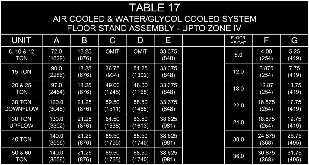
11 CABINET ACCESSORIES & OPTIONS (i) Upflow Supply Plenum With Front Grille And Optional Left and/or Right Side Grille (ii) Top Return Plenum a. With Integrated Filter Box (ii) Top Return Plenum b. With Backdraft Damper (ii) Top Return Plenum c. With Backdraft Damper And Outside Air Damper (iii) Floor Stand a. Upto Zone IV (iii) Floor Stand b. With Backdraft Damper System 2100-R407C I Page 11
 Split Cabinet - Upflow b.")
 Split Cabinet - Downflow b.")
12 CABINET ACCESSORIES & OPTIONS (iv) Split Cabinet - Upflow a. Two Piece Evaporator Section (iv) Split Cabinet - Upflow b. Three Piece Evaporator Section (v) Split Cabinet - Downflow a. Two Piece Evaporator Section (v) Split Cabinet - Downflow b. Three Piece Evaporator Section Verify With Factory For Split Cabinet Configuration On Non-Standard Airflow Units System 2100-R407C I Page 12

13 SYSTEM FEATURES Standard For All Systems CABINET & FRAME System 2100 frame is constructed of heavy gauge 1.5 square inch heliarc-welded tubular steel for strength and protection. Exterior cabinet front and side access panels are constructed of heavy gauge cold-rolled steel. Access is made easy for servicing, as the cabinet is fitted with captive ¼ fasteners which allow controlled access for service and are positioned to enhance cabinet appearance. Access panels are well-insulated with NFPA 90A rated 1 thick 1.5 lbs. density fiberglass insulation. The cabinet has decorative front and side panels which can be color coordinated with the decor of the computer room. Standard colors available for the System 2100 are Black, Sky Blue or Cloud White. A FRAME COIL System 2100 has two DX cooling circuits provided with high efficiency fins and a larger coil face area. The A frame coil is designed to provide the maximum sensible heat ratio as required by the systems application. The larger coil face area and optimized circuit arrangement for both compressor systems not only minimizes the energy consumption but also provides precise control of temperature and humidity. Air bypass is provided to prevent saturated air from being introduced into the controlled space. Air is drawn through both circuits of the coil at low velocity providing effective surface exposure with minimum turbulence. Every unit is equipped with two drain pans. The primary stainless steel drain pan is provided under each coil. A secondary drain pan is provided at the base of the unit. This provides double protection against any water reaching the sub floor and affecting the computer cables. Each drain pan is piped with a condensate drain outlet. AIR BYPASS The units are equipped with a built-in air bypass (adjustable) to control the maximum relative humidity and limit the temperature variation of the discharge air. Discharge air will not exceed 80% R.H. under all normal computer room operating conditions. DUAL COMPRESSOR(s) Each System 2100 is equipped with two high efficiency Scroll Compressors located in a separate compartment, outside the air stream for ease of service access during unit operation. The scroll compressors high volumetric efficiency and a constant volume ratio give the scroll compressor an excellent EER rating. Compared to a reciprocating compressor the scroll compressor s capacity, power and current do not fall off as rapidly at high condensing and low suction temperatures. Scroll compressor can also accommodate liquid slugging, both oil and refrigerant without causing compressor damage. Scroll compressors contain fewer parts resulting in greater reliability. Sound attenuation is also much easier since the dominant sound characteristics are in the higher octave band and the unit enclosure usually is adequate. Vibration in the system is greatly reduced by elimination of the reciprocating masses found in the semi-hermetic compressor. Each compressor is provided with: Built-in thermal overload protection Crankcase heaters Rotolock valves Internal vibration isolation Charging and service schraeder ports Internal discharge gas vibration eliminator External vibration mounting isolation DUAL REFRIGERANT CIRCUIT(s) Each refrigerant circuit is provided with highly efficient refrigeration components. Externally equalized expansion valve Sight glass with moisture indicator Filter drier Pump down cycle (air cooled units) Schraeder fittings Hot gas bypass (when required) Suction accumulator when required System 2100-R407C I Page 14


14 SYSTEM FEATURES Standard For All Systems SAFETY FIRST! Each compressor system has an automatic reset low pressure switch for loss of refrigerant charge protection and manual reset high pressure switch for high pressure protection. Audio and visual alarms are provided with system shut down in the event of high/low pressure system failure. Keeping customers and service technicians in mind, all refrigeration components are located out of the air stream enabling the service technician to fully service and analyze the components, while not interrupting conditioned airflow to the controlled indoor environment. Note: Standard piping access is on the left hand side, when facing the unit. All refrigeration piping will be of refrigerant grade. DEHUMIDIFICATION CYCLE When a System 2100 unit is switched to the dehumidification mode, a call for cooling is energized via the advanced microprocessor and moisture is condensed on the cooling coil. The condensate is then discharged through the primary condensate drain. The reheat provided shall offset sensible cooling during dehumidification and has sufficient capacity to maintain computer room dry bulb conditions. ELECTRIC REHEAT System 2100 standard reheat is provided in multi-stage two, three or four stages. The low-watt density, electrically enclosed elements are surrounded by fin tubular construction elements, thus extending the life of the elements, reducing sheath temperatures and eliminating ionization. Reheat operation is protected by dual temperature limit controls. In the dehumidification mode the system selected has ample reheat capacity to maintain dry-bulb conditions. (See technical data for reheat information on system selected) STEAM GENERATING MODULATING HUMIDIFIER- CANISTER TYPE System 2100 is provided with a pre-piped and pre-wired electronic, electrode self-generating steam type humidifier. The humidifier shall have an adjustable humidity output setting of the full rated humidifier capacity. Furthermore, the total system never allows the leaving relative humidity to exceed 80% so that the threat of condensation beneath the application s floor is eliminated. The pure steam method eliminates air contaminating mineral deposits and excessive humidity inherent with evaporative or infra-red humidifiers. The steam generator requires no scheduled maintenance and is completely maintenance free. The humidifier has a modulating output control to match its output with humidity requirement signal. Humidifier shall come standard with an automatic flush cycle that senses the current consumption of the humidifier. The humidifier is equipped with disposable cylinder and an indicator that signals when the canister is to be changed, which insures a reliable and trouble free operation. The humidifier is complete with supply and drain valves, electronic controls and steam distributor. Vapor produced is piped directly into the bypass air for efficient moisture introduction into the air stream. (See technical data for humidifier information on system selected) HIGH VOLTAGE CONTROL PANEL System 2100 is equipped with a high voltage panel which is easily accessible from the front of the unit and can be accessed for full service without disrupting the air flow. All wiring conforms to National Electrical Code (NEC) and UL 1995 requirements. Electrical components utilized in the control panel are UL Listed and Recognized. Each AC power circuit is individually branch circuit protected on all phases. Each component (humidifier, compressors, motor, electric reheat stage) (if applicable) is provided with a factory mounted and wired definite purpose contactor. The control wiring is 24 VAC low voltage. The control panel has the following components: Disconnect Switch or Power block (if required) Relays Fuse blocks Fuses Control transformers Microprocessor controller Terminal blocks System 2100 requires a single point main power supply connection. System 2100-R407C I Page 15

 operate in the Class-I range, is (are) belt driven, and is (are) rated in accordance with AMCA Standard #210.")
15 SYSTEM FEATURES Standard For All Systems FAN/MOTOR ASSEMBLY System 2100 features double width, double inlet (DWDI), centrifugal, forward curved blower configuration mounted on a fan deck. The air conditioner is configured for drawthru air pattern to provide uniform airflow over the entire face area of the coil. Each fan is the centrifugal type with forward curved blades, both dynamically and statically balanced to minimize vibration. The blower(s) operate in the Class-I range, is (are) belt driven, and is (are) rated in accordance with AMCA Standard #210. The speed of the blowers is adjustable by means of a variable pitch motor pulley. Drive set and belts are sized for 200% of the motor horsepower rating, and are oil and heat resistant and static conducting. The blower has permanently lubricated ball bearings, with an average life span of 100,000 hours. The blower shaft is cold finished center-less ground heavy-duty steel, treated for rust protection. The steel shaft conforms to ASTM A-108 specifications. AIR FLOW SWITCH System 2100 is equipped with airflow switches that continuously monitor the supply airflow and turn the unit off with alarm in case of loss of airflow. The unit also monitors pressure drop across the air filters and provide dirty filter alarm (indication only). Field calibration is required for dirty filter alarm. FILTER SECTION System 2100 has standard 2 inch deep, 30% (MERV-8) pleated media high efficiency filters, (based on ASHRAE Std ). The Filter section is serviceable from the top or either side on down-flow units and from the front or right-hand side on up-flow units. The fan section features the following: Permanently lubricated, self-aligning ball bearings Dual belt variable pitch drive-providing adjustable air flow capability to match the load requirements Fan deck to minimize vibrations Draw through airflow for even air distribution over A frame coil, static sealing of the filter section and low internal cabinet pressure losses Low noise level fan designed for quite operation Motors are high efficiency open drip proof (ODP) type. Motors are mounted on an adjustable slide base with a locking assembly to prevent motor play and have internal overload protection. The motors are 1725 RPM with copper windings, phase isolation and are UL component recognized. The motors have a minimum NEMA service factor of 1.15 System 2100-R407C I Page 16

16 SYSTEM FEATURES Standard For All Systems ADVANCED MICROPROCESSOR CONTROL PANEL (MCP) - SYSTEM 2200 PLUS (+3L) System 2200 Microprocessor +3L represents the top of our range of control boards, and has been designed to satisfy a wide range of applications in the field of specialized air-conditioning for precise temperature & humidity control. The System L is a programmable controller made up of a microprocessor based main board equipped with a set of terminals used to interface the microcontroller board to the controlled devices; such compressors, fans, heaters, humidifiers and valves. The program is retained in a flash based memory and configuration parameters are permanently stored (even in the case of power failure) in a non-volatile memory. The microprocessor features a 16-bit microprocessor and flash memory to ensure greater performance. The high capacity of the flash memory (0 MB expandable up to 0 MB), ensures all the alarm situations, the main value controls (temperature, pressure, & humidity) and the status of the devices controlled (compressors, fans, pumps) can all be saved. The control board is supplied in plastic enclosures that guarantee the high mechanical protection of the board and reduces the risk of electrostatic discharge due to incorrect handling, quick DIN rail mounting means faster assembly and wiring. The technology used on the System L allows connection to some of the more widely used communication standards without requiring an additional gateway. System L also includes a microprocessor based teminal unit complete with Graphical Touch Screen Display with a built-in navigation keypad and led indicators allowing the users to easily set the controlled parameters for set points, dead bands, alarm thresholds and carry out the main working operations (on/off, displaying controlled variables, printouts). The controller and graphical display terminal are powered by 24VAC power supply using low voltage control transformers from the unit. Connection between the terminal unit and main board is necessary only when programming the basic parameters on the System L. The controller is linked to a graphic display terminal via standard three wire cable. The graphical touch screen display, has a 4 rows X 40 character, back lit, super-twist liquid crystal display (LCD) panel and control keys for user inputs. The MCP is menu driven with user-friendly prompts for easy operation. The System 2200 MCP allows user review and programming of temperature and humidity set points, setup selections and alarm parameters. A password is required to make system changes and the system is provided with internal-diagnostics. The microprocessor controller runs the diagnostics and the analysis is displayed on the graphical interface including all component failure alarms. Inputs for temperature, humidity and time delay are displayed on the LCD. The MCP provides monitoring of room conditions, operational status, component run times, date and time, and 2 analog inputs from field sensors provided by others. System 2200 MCP control system allows programming of: Temperature set point (40 F to 85 F) Temperature sensitivity (+1 F to 9.9 F in 0.1 F increments) Humidity set point (20% to 80% RH) Humidity sensitivity (+1% to 30% RH) All set points are adjustable from the unit front panel. Temperature and humidity sensors are capable of being calibrated from the front panel. System 2200 Microprocessor provides the user with two control types: Proportional (P) and Proportional Integral (PI). Proportional uses set points and band to control the system and Proportional Integral is time selective. Support System The microprocessor is equipped with a non-volatile memory to permanently maintain programmed parameters, in case of power interruption. Standard Features Stand alone panel Smooth keyboard type switches with tactile feedback Two (2) analog inputs Non-volatile memory Data of unit and room conditions System trending Forward & back-up menu access Customized control capability System 2100-R407C I Page 17

17 SYSTEM FEATURES Standard For All Systems Protective & Safety Features Watch-dog timer Multi-Level password access Two remote alarms Manual diagnostics* Adjustable alarm limits Alarm displayed in order of occurrence Compressor short cycle Start time delay Programmable automatic restart Coil temperature high/low alarm set points* Water in/out alarm set point* Fire-stat safety Automatic Control Functions Compressor short cycle control System auto or manual restart Sequential load activation Common alarm relay Compressor lead/lag Schedule on/off control* Compressor Short-Cycle Control Prevents compressor short cycling by field adjustable 3-minute minimum on/off timer. System Auto-Restart For start-up after failure automatic restart is provided with a field adjustable delay up to 60 seconds in 1-second increments. Sequential Load Activation After power failure, or during start-up, the microprocessor panel will sequence operational load activation. Common Alarm System 2200 Microprocessor is field programmable to interface with user-selected alarms with a remote alarm device. Automatic Compressor Sequencing Automatically change the lead/lag sequence of the compressors after selected cycle time for equal compressor usage. Unit Stage time delay Inter-stage time delay Discharge alarm points* Outside humidity/temperature set points Water voltage range from VDC Audio alarm Restart mode (0-60 seconds) Fire-stat tripped ( fixed at 1000 F) Discharge set points* Monitored And Displayed Functions Current temperature (degree F/C) Current humidity (% RH) Cooling 1, 2 Heating stages 1, 2, 3, 4 Humidification Chilled water flow Dehumidification Run times for blower, compressors, reheat elements, humidifier, dehumidification Two (2) Analog Inputs for customer supplied sensors Econo-coil % Switch Functions System on/off switch Menu select button (up/down) Alarm silence/program button Exit menu key (up/down) Edit menu key (up/down) Programmable Functions Temperature set point (65-85 F/ C) Temperature sensitivity (1-5 F, C in 0.1 Increments) Humidity set point (40-60%) Humidity sensitivity (1-10% RH in 0.1% Increments) Temperature alarm points Humidity alarm points System 2100-R407C I Page 18
18 SYSTEM FEATURES Standard For All Systems Standard Alarms Activates a visual and audible alarm in the event of any of the following malfunction conditions: Room over temperature Room under temperature Room over humidity Room under humidity No air flow Change filters Fire-stat tripped Low voltage alarm Temperature sensor failure Humidity sensor failure Power failure restart Compressor short cycle Compressor high pressure 1, 2 Selectable alarm outputs Compressor low pressure 1, 2 Coil high/low temperature * No water flow (differential pressure +/- 10) * High/low water in temperature * High/low water out temperature * High limit heaters Firestat Firestat is programmed within the microprocessor. When return air temperature exceeds 100 F it immediately de-energizes the system and displays an alarm condition. Required by electrical code in certain localities. Optional Alarms Under floor leak detected Smoke alarm Fan motor overload Discharge sensor failure Manual override Custom Alarms Each alarm can be field programmed to be enabled or disabled, selected to activate the common alarm. Humidifier failure 2nd Alarm relay to select a specific alarm to close or open this relay Water flow Stand by pump alarm Defrost coil alarm * For features requiring optional/ custom sensors or components, contact factory for a detailed analysis of your requirements. System 2100-R407C I Page 19
19 AIR COOLED SYSTEM Air Cooled System Standard Features AIR COOLED CONDENSER (ACC) Remote air-cooled condenser is a low profile design constructed of corrosion resistant aluminum. The condenser cabinet houses the condenser coil, controls, fan(s) and fan motor(s) (compressors are located within the evaporator section). Air-cooled condenser utilizes multiple direct drive propeller fans and dual refrigeration circuits. The condenser coil is constructed of copper tube and high efficiency aluminum fin. A factory wired control panel is provided in a weatherproof housing on the air-cooled condenser. Control panel includes control transformer, motor contactor(s), and variable fan speed controller. Standard air cooled condensers are sized to provide the total heat of rejection at 95 F ambient temperature at sea level. Air-cooled condensers are rated for higher/lower ambient temperatures and/or higher altitudes. See Air Cooled Condenser Engineering Manual For Additional Information. LOW AMBIENT CONTROL Low ambient control system features a variable speed motor specially designed to be used in conjunction with a solid-state speed controller. The speed controller senses the head pressure of both compressors and varies the speed of the lead fan to maintain constant condensing temperature. Additional fan motors are controlled by ambient sensitive thermostats. This low ambient control allows system operation as low as -20 F ambient temperatures. See Air Cooled Condenser Engineering Manual For Additional Information. System 2100-R407C I Page 20
20 AIR COOLED SYSTEM Air Cooled System Optional Features LOW AMBIENT CONTROL FOR AMBIENT UPTO -30 F Combination fan control/limitizer head pressure control with flooded receivers is provided for each refrigeration circuit. Air-cooled condenser shall be provided with factory installed and pre-piped head pressure control valve for each refrigeration system. Heated and insulated liquid receivers are provided in a separate enclosure for field installation near the condenser. Receivers to be field wired to the condenser control panel. (Equivalent refrigeration line runs between indoor unit and condenser unit is required. Consult factory for more detail) AIR COOLED CONDENSER-LOW NOISE (ACC-LN) Remote air-cooled condenser is a low profile design constructed of corrosion resistant aluminum. The condenser cabinet houses the condenser coil, controls, fan(s) and fan motor(s) (compressor is located within the evaporator section). Air-cooled condenser utilizes multiple direct drive propeller fans and dual refrigeration circuits. The condenser coil is constructed of copper tube and high efficiency aluminum fin. A factory wired control panel is provided in a weatherproof housing on the air-cooled condenser. Control panel shall include control transformer, motor contactor(s), and variable fan speed controller. Standard air cooled condensers are sized to provide the total heat of rejection at 95 F ambient temperature at sea level. Air cooled condensers can be rated for higher/lower ambient temperatures and/or higher altitudes. CENTRIFUGAL FAN TYPE AIR COOLED CONDENSER (ACCB) Recommended for indoor and outdoor use where quiet operation is desirable. Accommodates itself to installations, which are unsuitable for a direct drive propeller fan type air-cooled condenser. Allows for ducted intake and discharge. The air-cooled condenser (ACCB) is a selfcontained unit with front air discharge designed for indoor installation. The ACCB is equipped with DWDI centrifugal fan, belt driven motor and permanent lubricated ball bearing. The system has a total heat rejection capacity as shown in the technical data sheet. PIGGY-BACK AIR COOLED CONDENSER (ACC-PB) Recommended for high-rise building applications, where the use of a standard propeller fan type air cooled condenser is not practical. ACC-PB is Vertical standing type air cooled condenser for indoor use. ACC-PB frame is constructed of heavy-gauge 1.5 square inch heli-arc-welded tubular steel for strength and protection. Exterior cabinet front and side access panels shall be constructed of heavy gauge cold-rolled steel manufactured in the USA. Access is made easy for servicing, as the cabinet is fitted with captive ¼ fasteners which allow controlled access for service and are positioned to enhance cabinet appearance. The cabinet has decorative front and side panels which can be color coordinated with the decor of the evaporator section. ACC-PB features double width, double inlet (DWDI), centrifugal, forward curved blower configuration mounted on a fan deck. The air-cooled condenser is configured for draw-thru air pattern to provide uniform airflow over the entire face area of the coil. Each fan is the centrifugal type with forward curved blades, both dynamically and statically balanced to minimize vibration. The blower(s) shall operate in the Class-I range, shall be belt driven, and rated in accordance with AMCA Standard #210. The speed of the blowers shall be adjustable by means of a variable pitch motor pulley. Belts shall be sized for 200% of the motor horsepower rating, and shall be oil and heat resistant and static conducting. The blower has permanently lubricated ball bearings, with an average life span of 100,000 hours. The blower shaft is cold finished center-less ground heavy-duty steel, treated for rust protection. The shaft shall conform to ASTM A-108 specifications. Motors are high efficiency open drip proof (ODP) type. Motors are mounted on an adjustable slide base with a locking assembly to prevent motor play and have internal overload protection. The motor is 1725 RPM and will have copper windings, phase isolation and is UL component recognized. The motors shall have a minimum NEMA service factor of 1.15 System 2100-R407C I Page 21
21 WATER COOLED SYSTEM Water Cooled System Standard Features CO-AXIAL WATER CONDENSER(s) Each evaporator refrigerant circuit shall be provided with a factory installed single pass water-cooled condenser(s). Condensers are of the heavy duty, tube-in-tube co-axial counter flow type. The co-axial condenser(s) are constructed of longitudinal, spirally-wound applied fins with an outer tube serving as a shell. Longitudinal fins assure maximum heat transfer with low pressure drop for efficient heat transfer. Spirally-wound fins give free passage for condensing fluids. WATER REGULATING VALVE(s) Each refrigerant circuit is provided with a factory installed head pressure operated two (2) way water regulating valve rated for 150 psig. Valves accurately control the condensing temperature for varying entering water temperatures thus automatically controlling each circuit s head pressure. (Optional higher rated psig valves available) Water Cooled System Optional Features CLEANABLE CONDENSERS - SHELL & TUBE Each refrigerant circuit is provided with individual glycol/water cooled condenser. The glycol/water cooled condensers are of heavy duty, shell and tube, counterflow type with removable heads. Constructed of cupranickel with cast iron heads, mechanically cleanable. The shell sides of the condensers act as a receiver and holds refrigerant charge during pump down. Condenser is ASME rated for a maximum refrigerant pressure of 400 psig. THREE (3) WAY WATER REGULATING VALVE Each condenser circuit is provided with a factory piped three-way water-regulating valve, which allows for a constant pump operation. HIGH PRESSURE WATER REGULATING VALVE Available where a waterside pressure exceeds 150 psig. Good up to 300 psig. WATER FLOW SWITCH (INDOOR UNITS ONLY) For installation requiring indication of flow interruption. The pressure differential switch is installed and piped within system. System 2100-R407C I Page 22
22 GLYCOL COOLED SYSTEM Glycol Cooled System Standard Features CO-AXIAL WATER CONDENSER(s) Each evaporator refrigerant circuit shall be provided with a factory installed single pass water-cooled condenser(s). Condensers are of the heavy duty, tube-in-tube co-axial counter flow type. The co-axial condenser(s) are constructed of longitudinal, spirally-wound applied fins with an outer tube serving as a shell. Longitudinal fins assure maximum heat transfer with low pressure drop for efficient heat transfer. Spirally-wound fins give free passage for condensing fluids. WATER REGULATING VALVE(s) Each refrigerant circuit is provided with a factory installed head pressure operated two (2) way water regulating valve rated for 150 psig. Valves accurately control the condensing temperature for varying entering water temperatures thus automatically controlling each circuit s head pressure. (Optional higher rated psig valves available) DRY FLUID COOLER (DFC) The remote dry fluid cooler is low profile design constructed of aluminum housing with copper tube and high efficiency aluminum fin coil. It has multiple direct drive propeller fans. All fans are sized to maximum energy efficiency, minimum noise, and are individually balanced to minimize vibration. Motors on the dry fluid cooler shall have built in thermal protection. Motor assemblies are supported in all-welded, heavy gauge wire support structures. The wire structures shall be zinc-chromate coated for corrosion protection. A factory installed and wired control panel is provided in weather proof housing on the dry fluid cooler. GLYCOL/ WATER CIRCULATING PUMP PACKAGE The pump package will include pump starter, aqua-stats, and fan cycling contactor(s) to control the condenser glycol/water temperature. The pump package will include a close coupled, industrial duty pump with heavy-duty ball bearings motors, stainless steel shafts and bronze fitted construction 3,500 RPM centrifugal circulating pump close-coupled to a NEMA standard electric motor is provided for field mounting and piping. (1750-RPM pumps available, consult factory). The control panel will be factory provided for field installation in a weatherproof box provided on the dry fluid cooler. Pump package will be electrically interfaced with each dry fluid cooler and indoor evaporator via a 24-Vac low voltage connection. Seperate power supply is required (provided by others). Glycol Cooled System Optional Features CLEANABLE CONDENSERS - SHELL & TUBE Each refrigerant circuit is provided with individual glycol/water cooled condenser. The glycol/water cooled condensers are of heavy duty, shell and tube, counterflow type with removable heads. Constructed of cupranickel with cast iron heads, mechanically cleanable. The shell sides of the condensers act as a receiver and hold refrigerant charge during pump down. Condenser is ASME rated for a maximum refrigerant pressure of 400 psig. THREE (3) WAY WATER (GLYCOL) REGULATING VALVE Each Condenser circuit is provided with a factory piped three (3) way pressure actuated glycol-regulating valve rated at 150 psig, which allows for a constant pump operation. The water regulating valve shall assure proper head pressure regardless of glycol temperature and pressure. HIGH PRESSURE WATER REGULATING VALVE Available where a waterside pressure exceeds 150 psig. Good up to 300 psig. WATER FLOW SWITCH (INDOOR UNITS ONLY) For installation requiring indication of flow interruption. The pressure differential switch is installed and piped within system. DUAL PUMP PACKAGE Providing redundancy to avoid any pump failure and to keep your system continuously operating dual pump package includes two pumps, pressure differential switch, lead-lag switch and control box containing auto-change over controls are factory provided for field installation. The dual pump package includes close-coupled, industrial duty pumps with heavy-duty ball bearings motors, stainless steel shafts and bronze fitted construction. The pump package will include pump starters, aqua-stats, and fan cycling contactor(s) to control the condenser glycol temperature. The Pressure Differential (No Water Flow) Switch will sense the loss of flow, should the lead pump fail and automatically command the standby pump to start. Differential pressure switch is provided for field installation. The control panel is factory provided in a weatherproof box provided on the Dry Fluid Cooler. Dual pump package is electrically interfaced with each dry fluid cooler and indoor evaporator via a 24-Vac low voltage connection. Dual pump piping and wiring are field done by others. System 2100-R407C I Page 23
23 GLYCOL COOLED SYSTEM Glycol Cooled System Optional Features DUAL PUMP ENCLOSURE Dual pumps are protected with a base and complete vented weather enclosure from the ambient conditions. Enclosure is constructed of galvanized steel supported by factory-mounted rails. Enclosure can be color coordinated with the decor of the roof. Dual pumps are factory mounted in the enclosure ready for field piping and wiring STAND BY PUMP ON ALARM CONTACT CLOSURE If water flow is lost, the pump auto-change over controller will energize the backup pump and factory wired contact closure will send an alarm to the unit s microprocessor. On pump change over audible alarm shall sound at the indoor unit and a message Stand-By Pump On will be displayed on the unit s MCP. SINGLE PUMP ENCLOSURE Pump package is protected with a base and complete vented weather enclosure from the ambient conditions. Enclosure is constructed of galvanized steel supported by factory-mounted rails. Enclosure can be color coordinated with the decor of the roof. Dual pumps are factory mounted in the enclosure ready for field piping and wiring EXPANSION TANK 7.5 or 15 gallon tanks are available for field installation. DRY FLUID COOLER-LOW NOISE (DFC-LN) The remote dry fluid cooler is low profile design constructed of aluminum housing with copper tube and high efficiency aluminum fin coil. It has multiple direct drive propeller fans. All fans are sized to maximum energy efficiency, minimum noise, and are individually balanced to minimize vibration. Motors on the Dry Fluid Cooler have built in thermal protection. Motor assemblies are supported in all-welded, heavy gauge wire support structures. The wire structures are zinc-chromate coated for corrosion protection. A factory installed and wired control panel is provided in weather proof housing on the dry fluid cooler. CENTRIFUGAL TYPE DRY FLUID COOLER (DFCB) Recommended for indoor and outdoor use where quiet operation is desirable. Accommodates itself to installations, which are unsuitable for a direct drive propeller type dry fluid cooler. Allows for ducted intake and discharge. The dry fluid cooler is a self-contained unit with front air discharge designed for indoor installation. DFCB is equipped with DWDI centrifugal fan, belt driven motor and permanent lubricated ball bearing. The system has a total heat rejection capacity as shown in the technical data sheet. Glycol Cooled System Optional Features PIGGYBACK DRY FLUID COOLER (DFC-PB) Recommended for high-rise building applications, where the use of propeller fan type dry fluid cooler is not practical. DFC-PB is a vertical standing type dry fluid cooler for indoor use. DFC-PB frame is constructed of heavy gauge 1.5 square inch heli-arc-welded tubular steel for strength and protection. Exterior cabinet front and side access panels are constructed of heavy gauge cold-rolled steel manufactured in the USA. Access is made easy for servicing, as the cabinet is fitted with captive ¼ fasteners which allow controlled access for service and are positioned to enhance cabinet appearance. The cabinet has decorative front and side panels which can be color coordinated with the decor of the evaporator section. DFC-PB features double width, double inlet (DWDI), centrifugal, forward curved blower configuration mounted on a fan deck. The air conditioner is configured for drawthru air pattern to provide uniform airflow over the entire face area of the coil. Each fan is the centrifugal type with forward curved blades, both dynamically and statically balanced to minimize vibration. The blower(s) will operate in the Class-I range, will be belt driven, and rated in accordance with AMCA Standard #210. The speed of the blower will be adjustable by means of a variable pitch motor pulley. Belts are sized for 200% of the motor horsepower rating, and are oil and heat resistant and static conducting. The blower has permanently lubricated ball bearings, with an average life span of 100,000 hours. The blower shaft is cold finished center-less ground heavy-duty steel, treated for rust protection. The shaft conforms to ASTM A-108 specifications. Motors are high efficiency open drip proof (ODP) type. Motors are mounted on an adjustable slide base with a locking assembly to prevent motor play and have internal overload protection. The motor is 1725 RPM and has copper windings, phase isolation and is UL component recognized. The motor has a minimum NEMA service factor of 1.15 System 2100-R407C I Page 24
24 FREE COOLING SYSTEM Free Cooling - Dual Coil DX-Chilled Water System Standard Features Combo C Plus units are specifically designed for chilled water applications where mechanical cooling is required as back-up or is operated during off hours or weekends. Chilled Water Plus C+ systems can be integrated with Air Cooled, Water Cooled or Glycol Cooled Systems. This type of equipped also offers stand-by capability. Design of this type of equipment is similar to the energy miser. The chilled water coils are adequately sized so as to provide identical cooling capacity obtained during the refrigeration cycle with both compressors operating. Combo C Plus units are internally piped and wired to automatically change over to the direct expansion system when chilled water cooling or flow is interrupted for any reason. CHILLED WATER COIL The CW Coil shall be "A" frame and have face area as listed in the technical data sheet. The prime surface shall be seamless copper tubes with aluminum fins. Return bends shall be made of seamless copper tube. Coils are tested at 250 psig. Coils are rated in accordance with ARI Standard 420. Fins are aluminum plate type, die formed fin design to provide optimum strength and turbulence for maximum peak performance without objectionable high-pressure drop. The chilled water cooling coil is designed to provide totally sensible cooling. MODULATING CHILLED WATER CONTROL VALVE Unit shall be provided with factory piped and wired three (3) way modulating chilled water control valve. Valves shall accurately control the system s head pressure for varying entering water temperatures, thus automatically controlling each circuit s head pressure. During the chilled water cooling mode the microprocessor controller shall modulate the CW Valve as per the cooling requirement. (Optional higher pressure rated valves are available) Free Cooling - Dual Coil Glycol Cooled Energy Miser System Standard Features Compu-Aire Energy Miser system EM is integrated with Glycol Cooled System At entering glycol temperatures of 45 F and below, the Energy Miser EM system can provide total system capacity, thereby resulting in substantial reduction in operating costs. During free cooling mode when cooling is required, the microprocessor control panel signals a three-way free cooling valve to energize and the glycol/water solution is diverted to the free cooling coil thereby providing the necessary cooling at a fraction of the cost. The compressors remain off until needed. Ramp simultaneous cooling is allowed. FREE COOLING COIL Free cooling is located at the downstream side of the direct expansion coil. The free cooling coil is properly sized so as to provide the identical cooling capacity obtained during the refrigeration cycle with both compressors operating. The coil shall be "A" frame and have face area as listed in the technical data sheet. The prime surface is seamless copper tubes with aluminum fins. Return bends are made of seamless copper tube. Coils are tested at 250 psig. Coils are rated in accordance with ARI Standard 420. Fins are aluminum plate type, die formed fin design to provide optimum strength and turbulence for maximum peak performance without objectionable high pressure drop. The free cooling coil is designed to provide total sensible cooling. THREE (3) WAY MODULATING WATER VALVE A three (3) way modulating water-cooling control valve rated for 150 psig are factory installed. Valves shall accurately control the condensing temperature for varying entering water temperatures, thus automatically controlling each circuit s head pressure. The microprocessor controller modulates the valve as per the cooling requirement. System 2100-R407C I Page 25
25 SYSTEM FEATURES Optional For All Systems AIRFLOW CONFIGURATION Upflow with Front Return & Top Supply Up-flow version of the unit is available for installations where raised computer floors are not required and/or not available. The unit can be provided with a duct flange for ducted supply air distribution. Designed for in-the-space applications, were utilizing ductwork is practical. Return air entering through front grille and filters, conditioned air leaving through duct connection at top of unit. Supply Air Plenum is constructed of heavy gauge reinforced furniture grade steel panels and is insulated with 1, 1-1/2lb., density insulation. It is painted to match the unit color. Supply air grilles on front. (Floor stand is required) Upflow with Rear Return & Top Supply Designed for use in out-of space applications were return air entering through duct collar mounted on unit rear panel, conditioned air leaving through duct connection at top of unit. Upflow with Plenum & Front Return Up-flow version of the unit is available for installations where computer floors are not required and/or not available. The unit is provided with an air distribution discharge plenum with front supply grille, designed for in-the-space applications, were utilizing ductwork is not practical. Supply Air Plenum is constructed of heavy gauge reinforced furniture grade steel panels and shall be insulated with 1, 1-1/2lb., density insulation. It is painted to match the unit color. Plenum height shall be 20 or as required. Supply Air Grilles on Front. (Optional left and/or right side(s) are available) Upflow with Bottom Return & Top Supply Designed for use in-the space applications were return air shall come from the bottom of the computer room raised floor, conditioned air leaving thorough duct connection at top of unit. The unit is provided with an air distribution discharge plenum or can be ducted. Downflow with Rear Supply & Top Return Engineered for a typically computer room in-the-space application, with return air entering through filters at top, and conditioned air leaving through bottom rear. The fan housing is rotated to provide supply air to the rear. Downflow with Plenum Supply & Top Return Downflow version of the unit is available for installations where raised floors are not required and/or not available. The unit can be provided with a supply air distribution plenum where the unit sits on floor stand covered by supply air plenum. Designed for in-the-space applications. System 2100-R407C I Page 26
26 SYSTEM FEATURES Optional For All Systems SPLIT CABINET Two (2) Piece Split Cabinet The unit is split in two pieces for ease of entry to the computer room. Compressor compartment is made as separate piece and bolted together with the rest of the unit. Unit is factory tested and shipped as a one piece. Consult factory for more detail. Three (3) Piece Split Cabinet The unit shall be split in three pieces, Compressor compartment, Coil compartment, and blower compartment. Unit is factory tested and shipped as a one piece. Consult factory for more detail. OTHER CABINET OPTIONS Mirrored System As a standard feature a System 2100 system provides left-hand side access for piping and electrical connections. On some applications due to space constraints access on left hand side is not always available or at times when two systems are installed next to each other access on left-hand side for one of the systems in not practical. System 2100 systems can be provided with entire compressor section on the right hand side of the cabinet as oppose to the standard left hand side. This allows easier access, enabling two units to sit side by side, with one unit having access from the left-hand side and the other from the right-hand side. Piping connection will be from bottom right-hand side or optional top righthand side. Consult Factory for full details Piping Configuration Piping connection can be terminated from top left-hand side Double Wall Construction Cabinet exterior access panels shall be constructed of double wall construction. Each access panel shall be reinforced with additional heavy gauge metal with insulation on both panels allowing maximum vibration, noise attenuation and thermal insulation during system operation. High Density Grade Insulation Access panels are well insulated with NFPA rated 1 thick 3 lbs. density fiber glass type insulation. Rear Decorative Panels Rear panel(s) of the system, normally black, can be specified to match the selected cabinet color, especially if the unit it to be positioned in such a way that it is centrally located in the room. Floor Stand Floor stand is constructed of heliarc welded angle steel and is 8"-24" in height and shall have adjustable legs for height adjustability (± 2"). The floor stand allows the ease for installation and connection of the system prior to the installation of the raised floor. Adjustable floor stand raises the system above the sub floor to match the height of the raised floor. Note: Floor stand height shall be fixed once selected. Height adjustability of ± 2" shall be based on selected floor-stand height only. Seismic Base Zone IV Floor Stand Compu-Aire can provide seismic rated floor stands. In areas where seismic bracing is a concern, the floor-stand shall be constructed of heliarc welded tubular steel and shall be 8"-36" high and shall have adjustable legs for height adjustability (± 2"). Floor stand are rated for Seismic Zone IV application. Note: Floor stand height shall be fixed once selected. Height adjustability of ± 2" shall be based on selected floor-stand height only. Turning Vane (Scoop Only) Heavy gauge, factory installed turning vane (scoop only) provided with floor stand. Utilized to direct airflow. (Consult factory on specifications for vane assemblies) Back Draft Damper An automatic back-draft damper is provided at the outlet of the discharge elbow to prevent back flow of air. Motorized damper is available, consult factory. Vibration Isolation Pad(s) Ribbed Neoprene and cork sandwich pads are provided for field installation under mounting pedestals. Vibration Isolator(s) (Spring type) Vibration Isolators are equipped with isolation pedestals for ease of installation of sub floor and to prevent any vibration being directly transmitted to the access floor. System 2100-R407C I Page 27
27 SYSTEM FEATURES Optional For All Systems FILTERS High Efficiency Filters High efficiency filters for various requirements are available in lieu of standard 2" 30% (MERV-8) efficient filter. Optional high efficiency filters are available in 2" to 4" thick deep pleated filters, 30% to 80% efficiency (MERV-8 to MERV-13). High efficiency filters allow optimal air filtering for even the strictest air quality requirements. Pre-Filters In addition to the standard or optional high efficiency filters selected for the system, 2" 20% pre filters are provided to allow for additional filtering of return air. Note: Upgraded motors may be required for additional air pressure drop across filter section. REFRIGERATION OPTIONS Semi-Hermetic Compressors Dual high efficiency, heavy duty, cast iron, 1750 RPM, semi-hermetic, serviceable compressors, with gas cooled motor construction is available for each refrigerant system. Compressors are mounted on vibration isolators and have build in overloads, oil sight glass, manual reset high-pressure switch and auto reset low-pressure switch. Each refrigerant circuit is provided with hot gas muffler, liquid line filter dryer, sight glass and an adjustable externally equalized expansion valve. The muffler is factory installed in the hot gas line. Compressors are located in a separate compartment for ease of service without interrupting unit operation. Four(4)- Stage Cylinder Un-loader(s) Cylinder un-loaders are provided for capacity reduction during light load condition on semi-hermetic compressors. Used with Semi-Hermetic Compressors only. 4 Stage Sysytem - Includes cylinder un-loaders on one head of each compressor. Four stage of DX cooling shall be obtained as follows: Stage 1:One compressor unloaded, other compressor off Stage 2: One compressor on full Stage 3: One compressor on full, other compressor unloaded. Stage 4: Both compressors are on full. Hot Gas Bypass Hot gas bypass valve is provided on each refrigerant circuit. Unit are provided with factory piped Hot Gas Solenoid Valve (Air cooled units only) and Externally Equalized, direct acting Discharge Bypass Valve to provide capacity control and maintain the evaporator coil temperature under low load conditions. Used when a constant compressor function is desirable, allowing for compressor cycling and temperature fluctuations to minimize. (Hot gas bypass valve is standard on 15 ton and above units). Digital hot gas bypass is also available with electronic valve for digital capacity modulation control. Extended Four (4) Year Compressor Warranty This provides extension of standard one-year warranty to an additional four years on compressors from the date of start up. This additional warranty takes effect after expiration of the 1st year standard warranty. Total coverage is upto 5 years from the date of start up or 18 months from date of shipment, whichever comes first. This warranty is limited to supply of compressor FOB Whittier, CA freight both ways & installation labor to be paid by the customer. System 2100-R407C I Page 28

28 SYSTEM FEATURES Optional For All Systems REHEAT OPTIONS Steam Reheat Coil is factory piped with a two (2)-way on/off control valve. Strainer and trap are provided for field installation outside of the unit. Reheat coils are copper tube and aluminum fins of sufficient capacity to maintain dry bulb in the dehumidification cycle. Upgraded motor may be required for this option. Hot Water Reheat Factory piped with a two (2)-way on/off control valve. Reheat coils are copper tube and aluminum fins of sufficient capacity to maintain dry bulb in the dehumidification cycle. Modulating valve is also available. Upgraded motor may be required for this option. Hot Gas Reheat Factory piped hot gas reheat coil with a three (3) way heat reclaim valve and refrigerant check valve shall be provided. Hot gas reheat coil are seized to provide reheat capacity equal to the standard electric reheat capacity. Reheat coils are copper tube and aluminum fins of sufficient capacity to maintain dry bulb in the dehumidification cycle. Upgraded motor may be required for this option Extra Electric Reheat Additional electric reheat can be added to units provided with any other optional reheat source. SCR Reheat Control Factory installed and wired SCR controller modulate electric reheat rather than staging. Solid-state, noise-free device with no mechanical or moving parts to fail. SCR provides modulating of electric reheat output to help maintain a tighter control of room conditions. (Controller limit may apply. Consult factory for more detail) HUMIDIFIER OPTIONS Modulating Steam Generating Humidifier Canister Type Pre-piped and pre-wired electronic, electrode - self generating steam modulating type humidifier. The humidifier has a modulating output control to match its output with humidity requirement signal. (Controller limit may apply. Consult factory for more detail) Humidifier Lockout Relay Factory installed and wired relay. De-energizes humidifier when emergency power is utilized. Humidifier lockout relay prevents the operation of electrical loads that are not essential for continued site operation. Typically, used when facilities have limited back-up power capacity. Infrared Humidifier Provided with infrared quartz lamps mounted on a stainless steel pan as a complete assembly equipped with float valve and auto flush system. Serviceable without disconnecting high voltage wires. (Consult factory for availability) Steam-Grid Humidifier Dry steam, double jacketed type. Piped with a solenoid valve. Steam trap and Y-strainer to be factory provided and field installed outside of the unit. MOTORS Plug Fans Variable speed fan direct drive EC motors (plug fans), to regulate of cooling capacity and adjusting to changes in the thermal load of the server room Reheat Lock-Out Relay Factory installed and wired relay. De-energizes reheat when emergency power is utilized. Reheat lockout relay prevents the operation of electrical loads that are not essential for continued site operation. Typically, used when facilities have limited back-up power capacity. System 2100-R407C I Page 29
29 SYSTEM FEATURES Optional For All Systems MOTORS, PUMPS & BLOWERS Upgraded Motor/Blower Package System 2100 up-flow units are provided with upgraded motor/blower package to accommodate for high external static pressures requirements, special filters or increased CFM. (Consult factory for application requirements). High Efficiency Motors Premium efficiency motors are available as open-drip proof (ODP) or totally enclosed fan cooled (TEFC). The blower motor shall be mounted on an adjustable base, provided with a locking assembly to prevent motor play. The motor shall be 1765 RPM and shall have copper windings, phase isolation and shall be UL component recognized. The motors shall have a minimum NEMA service factor of Fan/Motor Isolation Fan & motor section are isolated from cabinet. Complete motor-blower assembly is mounted on vibration isolators to minimize the vibration transferred to the unit frame. Condensate Pump The Condensate Pump can be unit mount and wired at the factory or may be field installed by others. The condensate pump is complete with integral float switch, sump, motor, pump and automatic control. Check valve are field provided and installed by others. Condensate Pump is available in 115V, 208V or 460V. Primary drain and humidifier drain is piped to condensate pump for removal of condensate. A unit mount condensate pump is wired to main control panel on unit. Condensate pump for field installation requires a separate power source. Condensate pump rated for ' of head and high condensate temperatures caused by humidifier flush and drain cycle of canister type humidifier. Variable Frequency Drive Variable Speed Drive is available for capacity control. The advance microprocessor synchronies the blower speed with the current demand in the space and consequently the cooling demand of the room. Variable frequency drive shall have automatic bypass included. Note: Inverter Duty Motors will have factory mount and installed shaft grounding rings which divert motor shaft currents away from the bearings. ELECTRICAL OPTIONS Locking Disconnect Switch Non-automatic disconnect switch is mounted on the high voltage section of the electrical panel. Handle of disconnect switch is accessible from the front of exterior panel. Access to high voltage panel is permitted after the switch is in the OFF position. Disconnect switch shall allow lockout of main power supply to system during maintenance or service Single Phase Unit Where three-phase power is not available, a single-phase unit can be provided (maximum 10 tons). HACR Circuit Breaker 208 V, 460 V, 575 V HACR Circuit Breaker is mounted on the high voltage section of the electrical panel. Low Voltage Dropout Shuts the system to off, when sensing voltage level below 10% of the rated incoming voltage. The system requires manual resetting and voltage drop is field adjustable. Phase Monitor (3-phase units only) Automatic voltage range selection type phase monitor is provided internally wired, and installed inside the control box. Phase monitor provides protections against Phase loss, Phase reversal, Over voltage, Under voltage and Unbalanced Voltages. Phase monitor shuts the unit down on any of the above conditions. Automatic Transfer Switch Factory supplied, field installed (by others) switch shall be provided. Switch shall automatically transfer critical load to backup power source in event of power outage. Allowing the system to continuously maintain controlled environment. Verify with factory for unit installed ATS. 200,000 Hour (L-10) Pillow Block Bearings The blower shall have permanently lubricated pillow block bearings, with an average life span of 200,000 hours. System 2100-R407C I Page 30
30 SYSTEM FEATURES Optional For All Systems AIR COOLED CONDENSER & DRY FLUID COOLER OPTIONS Specially Treated Coils Available where air cooled condensers and the dry fluid coolers are subject to contaminating or corrosive air stream. Special coatings can be applied to reduce corrosion. Copper fin/copper tube coils are also available. Rain-Tight Disconnect Switch Available for Air Cooled Condenser and Dry Fluid Cooler. NEMA rated disconnect switch is provided for field installation. CONDENSATE LEAK DETECTION OPTIONS LDSP-420 Condensate Probe Type Leak Detection Sensor (water sensors) Spot type point-leak detection sensor, senses moisture under the floor. Provides leak detection at critical point under raised floor applications. Upon sensing moisture, unit mounted microprocessor shall sound an alarm and display message on the LCD and two (2) sensors can be provided for each system. Zone Leak Detection Monitoring System w/ Cable Factory provided leak detection monitoring system comes complete with monitoring unit and sensor cable. System provides monitoring of critical areas for water and water based liquids. Sensor cable is typically placed around the perimeter of a room or around a piece of equipment that is to be monitored for leaks. System continuously monitors the capacitance of the sensor cable and detects changes form the initial value. Leak Detection system is installed by others. Cable shall be 50 feet in length. Auxiliary Contacts Dry contacts for remote customer alarm providing notification of water detection. System 2100-R407C I Page 31
31 SYSTEM FEATURES Optional For All Systems CONTROL & MONITORING SOLUTION OPTIONS Remote Temperature/Humidity Sensors Remote temperature/humidity sensor is a wall mounted room sensor. Each sensor is an ideal solution to provide temperature and humidity inputs to the unit mounted microprocessor. Smoke Detector Mounted in return air section, smoke detector activates an alarm upon sensing smoke in the room and shuts down the system. Upon sensing smoke unit mounted microprocessor shall sound an alarm and display message on LCD. Smoke detector provided is used for system only. Auxiliary Contacts Dry contacts for remote customer alarm providing notification of smoke alarm Fan Overload Alarm Relay Fan overload relay alarm provides protection for the fan blower when it operates outside of normal condition. Once fan overload is detected, the normally open relay shall send a signal to the controller to shut the unit down to prevent potential damage. Temperature And Humidity Recorder 7 day, 24 hours, battery powered. Allows for temperature and humidity to closely recorded and allows close examination of customer s application. Comes complete with 100 recording charts and two bottles of ink. Building Management System Interfaces (BMS) BMS (Building Management Systems) are systems for the integrated management of all the technological functions of a building, one of them being air-conditioning. The development of these systems has meant that control systems made by different companies often need to be connected together, and consequently not only is a common electrical standard required, but also a common language, or communication protocol. The resulting advantages of such solutions (simpler and more efficient management of the building from a single control station, reduction in running costs, possibility of statistical analysis of all data, immediate identification of and response to faults and alarms) amply justify any extra cost of the individual devices. connectability they can offer. Compu-Aire,Inc. has always designed its controls to communicate with other systems, and has constantly followed the evolution of technology in the communications sector. For this reason, Compu-Aire,Inc. controllers, both parametric and programmable, can: - be integrated into systems consisting of instruments made by different manufacturers, with which they share information; - be managed remotely via modem and via Internet, even by simply using a browser; - inform remote personnel, wherever they may be, of any alarm situations, including by SMS messaging. "Proprietary" protocols, that is, those developed separately by individual companies, are now being replaced by "independent" standard protocols promoted by international organizations. Nonetheless, a single dominant standard has yet to emerge, and for this reason Compu- Aire,Inc. offers a wide range of solutions that allow its controllers to be connected to the main BMS. Compu-Aire has implemented compatibility with all the protocols that are emerging as the de facto standards in the HVAC/R and intelligent building management industry, and that are consequently used in the leading BMS: LonWorks / Modbus / BACnet / TCP/IP / SNMP / METASYS. Connection Mode Compu-Aire controllers is connected to the BMS in the following ways: - directly, without any intermediate devices, thanks to the ability of the microprocessor controller to select the protocol being used; - by connection to a gateway, that is, an external device that makes the hardware standards compatible and converts the Compu-Aire protocol to the protocol used by the BMS; - integrating the driver that manages the Compu-Aire protocol into the BMS. Today not only are the quality and the reliability of the instruments important, but also the degree of external System 2100-R407C I Page 32
32 SYSTEM FEATURES Optional For All Systems SENSORS & GAUGES Magnehelic Pressure Gauge Units are provided with Magnehelic Pressure Gauge in front of the unit to constantly read pressure drop across the filter. Discharge Air Sensor NTC sensor will be factory mounted and installed at outlet of fan indicating supply air temperature. System 2100-R407C I Page 33
33 TECHNICAL DATA Air Cooled System Table 1A CAA-832 CAA-1032 CAA-1232 CAA-1532 CAA-2032 MODEL CAA-834 CAA-1034 CAA-1234 CAA-1534 CAA-2034 CAA-835 CAA-1035 CAA-1235 CAA-1535 CAA-2035 NOMINAL TONNAGE NET CAPACITY DATA - Dual High Efficiency Standard Scroll Compressors, R-407C 80 F DB, 67 F WB (26.7 C DB, 19.4 C WB), 50%RH Entering Air Total - BTU/HR (kw) 124,200 (36.4) 136,100 (39.8) 192,500 (56.4) 248,500 (72.8) Sensible - BTU/HR (kw) 93,400 (27.4) 116,200 (34.0) 170,200 (49.8) 210,500 (61.6) 75 F DB, 62.5 F WB (23.9 C DB,16.9 C WB) 50%RH Entering Air Total - BTU/HR (kw) 105,000 (30.7) 122,600 (35.9) 136,600 (40.0) 180,200 (52.8) 224,700 (65.9) Sensible - BTU/HR (kw) 87,900 (25.7) 105,000 (30.7) 119,500 (35.0) 156,200 (45.8) 185,700 (54.4) 72 F DB, 60 F WB (22.2 C DB, 15.5 C WB) 50%RH Entering Air Total - BTU/HR (kw) 100,100 (29.3) 120,000 (35.2) 130,200 (38.2) 174,000 (51.0) 215,900 (63.3) Sensible - BTU/HR (kw) 86,000 (25.2) 102,800 (30.1) 116,700 (34.2) 152,000 (44.5) 182,500 (53.5) 80 F DB, 65.1 F WB (26.7 C DB, 18.4 C WB), 45%RH Entering Air Total - BTU/HR (kw) Sensible - BTU/HR (kw) 75 F DB, 61.1 F WB (23.9 C DB,16.2 C WB) 45%RH Entering Air Total - BTU/HR (kw) 102,000 (29.9) 118,000 (34.6) 131,500 (38.5) 176,300 (51.7) 219,500 (64.3) Sensible - BTU/HR (kw) 94,100 (27.6) 104,400 (30.6) 118,100 (34.6) 166,200 (48.7) 199,700 (58.5) 72 F DB, 58.6 F WB (22.2 C DB, 14.8 C WB) 45%RH Entering Air Total - BTU/HR (kw) 107,900 (31.6) 115,500 (33.8) 125,300 (36.7) 170,200 (50.0) 210,900 (61.8) Sensible - BTU/HR (kw) 92,000 (27.0) 114,000 (33.4) 115,300 (33.8) 160,400 (47.0) 178,200 (52.2) AIR DATA - Based on 0.5 inches external static pressure-variable pitch pulley CFM (L/s) 4,400 (2,077) 5,500 (2,596) 6,600 (3,115) 8,000 (3,776) 9,600 (5,192) Fan Motor - HP No. of Fans (Downflow) No. of Fans (Upflow) OPTIONAL AIR - for increased capacities or available static pressures; consult factory CFM (L/s) 5,500 (2,596) 7,050 (3327) 7,200 (3,398) 9,600 (4,531) 11,000 (5,900) Fan Motor - HP EVAPORATOR COIL DATA - High Efficiency, Copper Tubes / Aluminum Fins Face Area - Ft² (m²) 15.3 (1.42) 15.3 (1.42) 15.3 (1.42) 21.5 (2) 24.0 (2.23) Rows REHEAT - Electric kw BTU/HR, includes fan motor Stages HUMIDIFIER - Electronic self generating steam type with disposable cylinder kw Capacity - Lb/Hr (kg/hr) 17.5 (7.9) 17.5 (7.9) 17.5 (7.9) 30 (13.6) 30 (13.6) FILTER (Downflow Units) - 30% Efficient ASHRAE standard " x 25" x 2" " x 20" x 2" Effective Area - 2"; Ft² (m²) 56.0 (5.2) 56.0 (5.2) 56.0 (5.2) 68.7 (6.3) 73.9 (6.8) Effective Area - 4"; Ft² (m²) 84.2 (7.8) 84.2 (7.8) 84.2 (7.8) (10.0) (10.5) FILTER (Upflow Units) - 30% Efficient ASHRAE standard " x 20" x 2" " x 20" x 2" Effective Area - 2"; Ft² (m²) 44.6 (4.1) 44.6 (4.1) (5.3) 58.9 (5.5) PIPING DATA - All connections are Copper O.D. Condensate Drain - (Qty) Inch (2) 3/4" (2) 3/4" (2) 3/4" (2) 3/4" (2) 3/4" Liquid Line - (Qty) Inch 1/2" 1/2" 1/2" 1/2" 5/8" Hot Gas Line - (Qty) Inch 5/8" 5/8" 5/8" 7/8" 1 1/8" Humidifier Water Supply 1/4" 1/4" 1/4" 1/4" 1/4" UNIT WEIGHT - Lb (kg) 1,325 (601) 1,435 (651) 1,515 (687) 1,570 (712) 1,810 (821) AIR COOLED CONDENSER DATA - Based on 95 F (35 C) ambient, for other ambient conditions refer to heat rejection manual Model ACC-09 ACC-11 ACC-13 ACC-17 ACC-24 CFM (L/s) 4,800 10,400 10,200 9,800 14,750 Motor - (Qty) HP (1) 4/5 (2) 4/5 (2) 4/5 (2) 4/5 (3) 4/5 Liquid Line - (Qty) Inch (2) 7/8" (2) 7/8" (2) 7/8" (2) 7/8" (2) 7/8" Hot Gas Line - (Qty) Inch (2) 1 1/8" (2) 1 1/8" (2) 2 1/8" (2) 1 3/8" (2) 1 3/8" Coil Face Area - Ft² (m²) 9.8 (0.91) 19.2 (1.8) 19.2 (1.8) 19.2 (1.8) 28.6 (2.6) Coil Rows ACC WEIGHT - Lb (kg) 305 (138) 340 (154) 355 (161) 400 (182) 560 (245) System 2100-R407C I Page 34
34 TECHNICAL DATA Air Cooled System Water Cooled System MODEL CAA-8-K CAA-10-K CAW-8-K CAW-10-K NOMINAL TONNAGE CAPACITY DATA 80 F DB/ 67 WB (26.7 C DB/ 19.4 C WB) Total - BTU/HR 111, , , ,500 Sensible - BTU/HR 92, ,100 95, , F DB/ 62.5 F WB (23.0 C DB/16.9 ) Total - BTU/HR 97, , , ,300 Sensible - BTU/HR 88, ,400 91, , F DB/60 F WB (22.2 C DB/15.5 ) Total - BTU/HR 76, ,300 78, ,100 Sensible - BTU/HR 76, ,100 78, ,200 AIR DATA CFM 4,400 5,500 4,400 5,500 Fan Motor - HP Blower Quantity OPTIONAL AIR DATA (With plug fans) CFM 5,600 7,050 5,600 7,050 Fan Motor - HP COMPRESSOR DATA (Refrigerant R407C R410A OR R134a) Type Hermetic Scroll Quantity EVAPORATOR COIL Face Area Ft² Rows REHEAT (Electric) kw BTU/HR 56,300 56,300 56,300 56,300 HUMIDIFIER STEAM GENERATOR LBS/Kw 10/ /6.8 10/ /6.8 FILTER DATA 30%, BASED ON ASHRAE Filters (Upflow) (4)20"X 20" X 2" Filters (Downflow) (2)20"X 25" X 2" ELECTRICAL DATA 208/3/60 FLA MCA MFS /3/60 FLA MCA MFS /3/60 FLA MCA MFS Version: Januar y, 2013 System 2100-R407C I Page 35

35 DIMENSIONAL DATA Optional Plenum Height Available Verify With Factory System 2100-R407C I Page 48
36 DIMENSIONAL DATA System 2100-R407C I Page 49
37 DIMENSIONAL DATA Optional Plenum Height Available Verify With Factory System 2100-R407C I Page 50

38 DIMENSIONAL DATA System 2100-R407C I Page 51

39 DIMENSIONAL DATA System 2100-R407C I Page 52
40 DIMENSIONAL DATA System 2100-R407C I Page 53
")
 Plenum")

41 DIMENSIONAL DATA NOTE: 1. Verify Dimensions With Factory For The Following Assemblies: a) Non-Standard Airflow Configurations b) Split Cabinet Units c) Floor Stand With Motorized Damper and/or Outside Air Economizer d) Plenum Box With Motorized Damper and/or Outside Air Economizer e) Piggy Back Condenser 2. For Heat Rejection Units Verify Dimensions In Heat Rejection Manual. System 2100-R407C I Page 54
RTU. Roof Top Units 8 30 Ton. Maxi-Kool.
 Maxi-Kool RTU Roof Top Units 8 30 Ton www.compu-aire.com MK A-3 034 -RTU Maxi-Kool Type Air Cooled - A Chilled Water Cooled - C Glycol Cooled - G Water Cooled - W Nominal Tonnage 8 30 Ton Voltage 2-208
System Floor Mount Systems DX / Glycol / Chilled Water 6-12 Tons. High Density Presicion Cooling. Kompact.
 High Density Presicion Cooling Floor Mount Systems DX / Glycol / Chilled Water 6-12 Tons System 2100 Kompact www.compu-aire.com CA A - 8 34 -K System 2100 K Type Air Cooled - A Chilled Water Cooled - C
Series 6. Guide Specification 60 Hz. MISSION CRITICAL Air Conditioning Systems. ClimateWorx International Inc.
 MISSION CRITICAL Air Conditioning Systems Series 6 Guide Specification 60 Hz S6-GS-602017.doc ClimateWorx International Inc. 14 Chelsea Lane, Brampton, Ontario, Canada L6T 3Y4 Series 6 Guide Specification-60
Data Aire LCS TM (Large Ceiling System) R-410A. 6, 8, 10, and 13 ton. ISO 9001 Certified
 R-410A. 6, 8, 10, and 13 ton. ISO 9001 Certified") Data Aire LCS TM (Large Ceiling System) 6, 8, 10, and 13 ton ISO 9001 Certified LCS TM (LARGE CEILING SYSTEMS) DX Product Description Performance and Electrical Data 3 the pioneer and builder of the most
Data Aire LCS TM (Large Ceiling System) 6, 8, 10, and 13 ton ISO 9001 Certified LCS TM (LARGE CEILING SYSTEMS) DX Product Description Performance and Electrical Data 3 the pioneer and builder of the most
Series 8. Guide Specification 60 Hz. MISSION CRITICAL Air Conditioning Systems. ClimateWorx International Inc.
 MISSION CRITICAL Air Conditioning Systems Series 8 Guide Specification 60 Hz S8-GS-602017.doc 2014 ClimateWorx International Inc. 14 Chelsea Lane, Brampton, Ontario, Canada L6T 3Y4 Series 8 Guide Specification-60
Data Aire LCS TM (Large Ceiling System) R-407C. 6, 8, 10, and 13 ton. ISO 9001 Certified
 R-407C. 6, 8, 10, and 13 ton. ISO 9001 Certified") Data Aire LCS TM (Large Ceiling System) 6, 8, 10, and 13 ton ISO 9001 Certified LCS TM (LARGE CEILING SYSTEMS) with refrigerant Product Description Performance and Electrical Data Dimensional Data Guide
Data Aire LCS TM (Large Ceiling System) 6, 8, 10, and 13 ton ISO 9001 Certified LCS TM (LARGE CEILING SYSTEMS) with refrigerant Product Description Performance and Electrical Data Dimensional Data Guide
B. Unit construction shall comply with ASHRAE 15 Safety Code, NEC, and ASME applicable codes (U.S.A. codes).
.") Guide Specifications PART 1 GENERAL 1.01 SYSTEM DESCRIPTION Microprocessor controlled, air-cooled liquid chiller utilizing scroll compressors, low sound fans, hydronic pump system and optional fluid storage
Guide Specifications PART 1 GENERAL 1.01 SYSTEM DESCRIPTION Microprocessor controlled, air-cooled liquid chiller utilizing scroll compressors, low sound fans, hydronic pump system and optional fluid storage
Flexible & Innovative. Cooling Solutions
 Flexible & Innovative Cooling Solutions Flexible & Innovative Compu-Aire Inc. offers a variety of high performance precision cooling systems that can adapt to your application needs. With today s rapidly
Brown University Revised August 3, 2012 Facilities Design & Construction Standards SECTION AIR HANDLING UNITS
 SECTION 23 70 00 AIR HANDLING UNITS PART 1. GENERAL 1.1 Section includes air-handling units to 15,000 cfm and accessories. 1.2 Related Sections 1 : A. Division 01 - Brown University Standard for Narragansett
Control Systems. Design & Manufacturing. Eco-Friendly. High Performance
 Temperature & Humidity Control Systems Design & Manufacturing DX Air / Water / Glycol Cooled Air and Water Side Economizer Chilled Water Systems Eco-Friendly High Performance OPTIMAL COOLING SOLUTIONS
SECTION PACKAGED ROOFTOP AIR CONDITIONING UNITS
 SECTION 15732 - PACKAGED ROOFTOP AIR CONDITIONING UNITS PART 1 - GENERAL 1.1 SECTION INCLUDES A. Package roof top unit. B. Heat exchanger. C. Refrigeration components. D. Unit operating controls. E. Roof
AIR COOLED PACKAGED CHILLER
 AIR COOLED PACKAGED CHILLER UNIC sal is equipped to produce a wide range of COOLER Air conditioning and Refrigeration units, conforming to the international standards and works continually to improve its
TECHNICAL GUIDE DESCRIPTION SPLIT-SYSTEM AIR-COOLED CONDENSING UNITS MODELS: HF-07 FEATURES B-0703
 TECHNICAL GUIDE SPLIT-SYSTEM AIR-COOLED CONDENSING UNITS MODELS: HF-07 DESCRIPTION These Sunline 2000 units are completely assembled, piped and wired at the factory to provide one-piece shipment and rigging.
Shelf Units R-407C. 2, 3, and 4 ton. ISO 9001 Certified
 Shelf Units 2, 3, and 4 ton R-407C ISO 9001 Certified the pioneer and builder of the most complete line of precision cooling equipment Data Aire s first precision cooling system was developed by data processing
Data Aire Series Air Cooled, Water/Glycol Cooled 6 through 30 Ton Dual Circuits R-407C
 Data Aire Series Air Cooled, Water/Glycol Cooled 6 through 30 Ton Dual Circuits R-407C 1 Data Aire the pioneer and builder of the most complete line of precision cooling equipment Data Aire s first precision
Data Aire Mini Ceiling Systems 1, 1.5, 2, and 2.5 ton capacities R-410A. ISO 9001 Certified
 Data Aire Mini Ceiling Systems 1, 1.5, 2, and 2.5 ton capacities R-410A ISO 9001 Certified Data Aire the pioneer and builder of the most complete line of precision cooling equipment Data Aire s first
Data Aire Series Chilled Water 7 through 50 ton
 Data Aire Series Chilled Water 7 through 50 ton ISO 9001 Certified Data Aire the pioneer and builder of the most complete line of precision cooling equipment Data Aire s first precision cooling system
Data Aire Mini Ceiling Systems 1, 1.5, 2, and 2.5 ton capacities R-410A. ISO 9001 Certified
 Data Aire Mini Ceiling Systems 1, 1.5, 2, and 2.5 ton capacities R-410A ISO 9001 Certified Data Aire the pioneer and builder of the most complete line of precision cooling equipment Data Aire s first
KINGS COUNTY JAIL EXPANSION PHASE III COUNTY OF KINGS SECTION
 SECTION 237433, PART 1 - GENERAL 1.1 RELATED DOCUMENTS A. Drawings and general provisions of the Contract, including General and Supplementary Conditions and Division 01 Specification Sections, apply to
Mission Critical. Series 6, 8 & 9. vertical floor mount Ton Units. Air Conditioning Systems
 Mission Critical Air Conditioning Systems vertical floor mount Series 6, 8 & 9 2-30 Ton Units Single Circuit for Superior Economy and Dual Circuit for Ultimate Protection Series 6 2-5 tons Compact Footprint
Liebert CSU3000 Chiller
 CSI 15620 - Packaged Water Chillers Liebert CSU3000 Chiller Guide Specifications for 7.5-37 Ton CS/CD/CT Models 1.0 GENERAL 1.1 CS/CD MODELS The main-frame coolant supply unit shall be a Liebert Model,
SECTION COMPUTER ROOM AIR CONDITIONING SYSTEMS
 PART 1 - GENERAL 1.1 RELATED DOCUMENTS A. Drawings and general provisions of the Contract, including General and Supplementary Conditions and other Specification Sections, apply to this Section. B. Related
Data Aire Series Air Cooled, Water/Glycol Cooled 6 through 30 Ton Dual Circuits
 Data Aire Series Air Cooled, Water/Glycol Cooled 6 through 30 Ton Dual Circuits 1 Data Aire the pioneer and builder of the most complete line of precision cooling equipment Data Aire s first precision
Modular Data Temp Systems Air Cooled Water/Glycol Cooled 8, 10 and 13 ton capacities R-410A. ISO 9001 Certified
 Modular Data Temp Systems Air Cooled Water/Glycol Cooled 8, 10 and 13 ton capacities ISO 9001 Certified the pioneer and builder of the most complete line of precision cooling equipment Back in the late
Modular Supply Make-Up Air Unit
 Modular Supply Make-Up Air Unit Model MSX Flexible Design Factory Assembled Heating Options Hot Water Steam Electric Cooling Options Evaporative Direct Expansion Chilled Water November 2009 Product Features
CeilMate TM Series 3 and 4 tons of cooling capacity. Ceiling Mounted Systems. Air Handler with Remote Condensing Unit Air Handler designed for R-410A
 A e r o S y s I n c o r p o r a t e d Ceiling Mounted Systems CeilMate TM Series 3 and 4 tons of cooling capacity Air Handler with Remote Condensing Unit Air Handler designed for R-410A AeroSys, Inc. 929
Modular Data Temp Systems Air Cooled Water/Glycol Cooled R-407C. 8, 10 and 13 ton capacities. ISO 9001 Certified
 Modular Data Temp Systems Air Cooled Water/Glycol Cooled 8, 10 and 13 ton capacities R-407C ISO 9001 Certified the pioneer and builder of the most complete line of precision cooling equipment Back in
SKY-COM HI-CAP SERIES. Precise Environmental Control SKY-COM 15 & 20 TON Series. Suited for Telecommunications, Laboratories and Computer Rooms
 SKY-COM HI-CAP SERIES Precise Environmental Control SKY-COM 15 & 20 TON Series Suited for Telecommunications, Laboratories and Computer Rooms GENERAL MECHANICAL SPECIFICATIONS AIRFLOW CONFIGURATION Units
C. ASME Compliance: Fabricate and label water chiller heat exchangers to comply with ASME Boiler and Pressure Vessel Code: Section VIII, Division 1.
 SECTION 236426 - ROTARY-SCREW WATER CHILLERS PART 1 - GENERAL 1.1 SUMMARY A. This Section includes packaged, water cooled or air cooled as scheduled, electric-motor-driven, rotary-screw water chillers
MACH N-407 Heat Pump Air-Cooled Chiller
 MACH060-01-N-407 Heat Pump Air-Cooled Chiller Heat Pump Air-Cooled Chillers for Global Residential and Light Commercial Microclimates MACH NOMENCLATURE BREAKDOWN MACH-060-01 - N - 407 Refrigerant Type
TECAM S.A. harmony. 5PZA Direct Expansion. Air Conditioning Equipment Manufacturer. R-410A PRECISION UNIT 2 Ton 6 Ton / 60 Hz. Tecnología Ambiental
 TECAM S.A. Tecnología Ambiental R-410A PRECISION UNIT 2 Ton 6 Ton / 60 Hz harmony 5PZA Direct Expansion Registration No.: SC 4696-1 Registration No.: CO-SC 4696-1 Air Conditioning Equipment Manufacturer
FULLY SELF-CONTAINED AIR CONDITIONING WITH INDUSTRIAL DURABILITY
 C A P A C I T Y R U G G E D, I N D O O R/ R E A D Y T O T O T A L L O C A L M A T C H E D O U T D O O R D E S I G N I N S T A L L S U P P O R T E N V I R O N M E N T A L C O N T R O L Liebert Industrial
1.1 This section applies to air handling units for HVAC Systems.
 AIR HANDLING UNITS GENERAL INFORMATION 1.1 This section applies to air handling units for HVAC Systems. DESIGN REQUIREMENTS 2.1 Design Criteria a. The decision to use modular central station air handling
SECTION PACKAGED ROOFTOP AIR CONDITIONING UNITS - CUSTOM
 SECTION 23 81 06 - PACKAGED ROOFTOP AIR CONDITIONING UNITS - CUSTOM PART 1 - GENERAL 1.1 SUMMARY A. This Section includes equipment types that contain all the components of the refrigeration process within
Service Step by Step Trouble-Shooting Check-List
 WARNING: Only Data Aire trained technician or experience technicians should be working on Data Aire Equipment. Protect yourself at all times and work safe. Date: Dates at the job site: From: to Job#: Serial#:
SECTION ROTARY-SCREW WATER CHILLERS
 PART 1 GENERAL 1.01 SECTION INCLUDES A. Factory-assembled packaged chiller. B. Charge of refrigerant and oil. C. Controls and control connections. D. Chilled water connections. E. Electrical power connections.
DSV Model Air Cooled Self Contained Indoor Packaged Units 3-5 Tons Preliminary Application Data
 DSV Model Air Cooled Self Contained Indoor Packaged Units 3-5 Tons Preliminary Application Data July 28, 2008 Page 1 1 of 3 PROJECT: TAG: Gross Cooling Capacity [Btuh]: 37,800* Design CFM: 1,200 Seasonal
UNIVERSITY OF ROCHESTER DESIGN STANDARDS NOVEMBER 1, 2013
 SECTION 15800 - AIR HANDLING EQUIPMENT 1.1 GENERAL A. All air handlers installed shall conform to the University of Rochester specification Guideline for Semi-Custom and Pre-Engineered Air Handling Units.
Chilled Water 7 to 211 kw
 Chilled Water 7 to 211 kw Data Aire the pioneer and builder of the most complete line of precision cooling equipment Data Aire s first precision cooling system was developed by data processing facility
Advance Release September 2009
 Vertical Air Cooled DSV Series R 410A Model DSV096 DSV120 DSV144 DSV180 Nominal Cooling (Tons) 8 10 12 15 Refrigerant R 410A R 410A R 410A R 410A Cooling Performance Gross Cooling Capacity(Btu/h) 95,000*
AIR HANDLER SPECIFICATION
 AIR HANDLER SPECIFICATION Air Handlers AH-1 through 5 The following air handlers will be supplied: AH-1 FX15-4842 Series 5700 CFM AH-2 FX15-4236 Series 3990 CFM AH-3 FX15-3633 Series 2570 CFM AH-4 FX15-3330
H3/V3 Series Horizontal and Vertical Indoor Air Handling Units. Engineering Catalog
 H3/V3 Series Horizontal and Vertical Indoor Air Handling Units Engineering Catalog Table of Contents AAON H3/V3 Series Features and Options Introduction... 6 H3/V3 Base Model Description... 7 Unit Size...
INTRODUCTION. Special Applications of Package Air Conditioners. Instant Cooling Requirement in Wedding Ceremonies
 Pakistan s Largest Manufacturers of Air-Conditioners PACKAGE TYPE UNIT FOR MOBILE APPLICATIONS Provides Turnkey Projects Conceptual Planning to Commissioning of HVACR Projects THE LARGEST MANUFACTURER
Series. Packaged Rooftop Units, heat pumps and Outdoor air handling Units. Features:
 RL Packaged Rooftop Units, heat pumps and Outdoor air handling Units Features: Air-cooled condenser, water-cooled condenser, or patented AAON evaporative-cooled condenser, with capacities from 45-240 tons
Internal ridged board 1" x 1.5 foil face installation shall be installed on roof, walls and base of casing.
 A-D WITH MPU SPECIFICATION WRITTEN SPECIFICATION Description A Modular Packaged Heating, Cooling and ventilating unit(s), as indicated on the drawings shall be furnished. Direct Fired Gas Unit(s) shall
Product Chillers A P P L I C AT I O N S
 Product Chillers A P P L I C AT I O N S Wineries Bottling Product Storage Product Ripening Meat Processing Florist Boxes Packaging Rooms Walk-in Coolers Beverage Boxes CENTURY PRODUCT CHILLERS Unit Configuration
SSL / SBS Sales Guide BLOWER-COILS REDUCED-FOOTPRINT, VERTICAL
 SO TOUGH, WE GUARANTEE IT. SSL / SBS Sales Guide BLOWER-COILS REDUCED-FOOTPRINT, VERTICAL SSL SBS www.superiorrex.com SSL / SBS Series: BIG ON FEATURES; SMALL IN SIZE Contractors All SSL/SBS model blower-coil
SECTION WATER-SOURCE UNITARY HEAT PUMPS
 SECTION 23 81 46 WATER-SOURCE UNITARY HEAT PUMPS PART 1 - GENERAL 1.1 RELATED DOCUMENTS A. Drawings and general provisions of Contract, including General and Supplementary Conditions and Division 1 Specification
RetroAire Model Number: 9,000 to 36,000 Btuh (2.6 to 10.5 kw)
") Indoor Single Package Vertical, Air-Cooled Heat Pump Unit RetroAire Model Number: Capacity Range: VPRH 9,000 to 36,000 Btuh (2.6 to 10.5 kw) Part 1 General 1.01 UNIT DESCRIPTION A. Indoor, single package
Indoor Single Package Vertical, Air-Cooled Heat Pump Unit RetroAire Model Number: Capacity Range: VPRH 9,000 to 36,000 Btuh (2.6 to 10.5 kw) Part 1 General 1.01 UNIT DESCRIPTION A. Indoor, single package
ENGINEERING MANUAL 3, 5, & 7 TONS PRECISION ENVIRONMENTAL CONTROL
 ENGINEERING MANUAL 3, 5, & 7 TONS PRECISION ENVIRONMENTAL CONTROL MODEL DESCRIPTION Table of Contents The LAYTON Advantage... Total Protection----------------------------------------------------------
VariCool VAV Engineering Guide
 Engineering Guide Effective September 2017 Water-Cooled and Chilled Water, Variable Air Volume Contents Product Features... 3 UNIT FEATURES... 3 Product Features... 4 Marvel Plus Microprocessor Control
SECTION AIR-COOLED SPLIT SYSTEM AIR CONDITIONING UNITS
 SECTION 23 62 13 - AIR-COOLED SPLIT SYSTEM AIR CONDITIONING UNITS PART 1 - GENERAL 1.1 RELATED DOCUMENTS: A. The Conditions of the Contract and applicable requirements of Division 1, "General Requirements",
VertiCool Aurora Engineering Guide
 Engineering Guide Effective August 2016 Air-Cooled, Water-Cooled and Water Source Heat Pump Contents Product Features... 3 Options... 4 Physical Data...5-6 Air-Cooled Performance Data (a) (b) (c)...7-8
C13-Series Engineering Guide
 Engineering Guide Effective January 2018 Horizontal Air-Cooled, Water-Cooled, Chilled Water and Heat Pump Contents Product Features............................... 3 Product Options................................
VERTICOOL TECHNICAL DATA MANUAL. Vertical Air/Water Cooled 3-25 Tons
 491 East Princess Street York, PA 17403 877-905-1111 717-843-4311 Fax: 717-854-4462 uca@unitedcoolair.com www.unitedcoolair.com VERTICOOL TECHNICAL DATA MANUAL Vertical Air/Water Cooled 3-25 Tons UNITED
MIN. CCT. QTY RLA LRA HP FLA AMPACITY /1/ /3/
 1 of 3 Cooling Capacity [Btuh] 24,800 * Condensing Unit SEER: 13.0 ** Condensing Unit CFM: 1,600 Condenser Fan No./Type: 1/CENTRIFUGAL Diameter x Width [in]: 10x10 Drive: Adjustable Belt Motor HP: 0.5
Guide Specifications for InRow Direct Expansion
 Guide Specifications Guide Specifications for InRow Direct Expansion THIS GUIDE SPECIFICATION IS WRITTEN IN ACCORDANCE WITH THE CONSTRUCTION SPECIFICATIONS INSTITUTE (CSI) MASTERFORMAT. THIS SECTION MUST
Series PACKAGED ROOFTOP UNITS, HEAT PUMPS AND OUTDOOR AIR HANDLING UNITS. Features:
 RZ PACKAGED ROOFTOP UNITS, HEAT PUMPS AND OUTDOOR AIR HANDLING UNITS Features: Air-cooled condenser, water-cooled condenser, or evaporative-cooled condenser packaged rooftop units from 55-240 tons Water-source
A. Section includes split-system air-conditioning units consisting of separate evaporator-fan and compressor-condenser components.
 Page 238126-1 SECTION 238126 - This Section includes requirements for the LEED Rating System. However, equipment specified in this Section may not qualify for LEED Rating System prerequisites and credits.
TECHNICAL GUIDE. Description SPLIT-SYSTEM AIR-COOLED CONDENSING UNITS YD360, 480 & THRU 50 NOMINAL TONS YTG-B-0811
 Description These units are completely assembled, piped and wired at the factory to provide one-piece shipment and rigging. Each unit is pressurized with a holding charge of Refrigerant R-410A for storage
100 TON AIR-COOLED SCROLL PACKAGED. Call us today! (800) SPECIFICATIONS GENERAL DIMENSIONS ELECTRICAL DATA ADDITIONAL INFORMATION
 SPECIFICATIONS GENERAL DIMENSIONS ELECTRICAL DATA ADDITIONAL INFORMATION") 100 TON AIR-COOLED SCROLL PACKAGED SPECIFICATIONS Call us today! (800)341-4297 Trane Portable Packaged Air Conditioner units contain the best compressor technology available, in order to achieve the highest
100 TON AIR-COOLED SCROLL PACKAGED SPECIFICATIONS Call us today! (800)341-4297 Trane Portable Packaged Air Conditioner units contain the best compressor technology available, in order to achieve the highest
Series PS6, Vertical Floor-Mount Units
 Series PS6, Vertical Floor-Mount Units Technical Data 60 Hz sps6em6ea.doc Dec-12 ClimateWorx International Inc. 14 Chelsea Lane, Brampton, Ontario, Canada L6T 3Y4 Table of Contents Table of Contents...
Mission Critical Air Conditioning Systems
 Mission Critical Air Conditioning Systems wall & ceiling mount Series 7 & 11 1-5 Ton Units Single Circuit Units Designed for Superior Space Utilization Series 7 1.5-2.5 tons Compact wall mounted split
Computer Room Air-Conditioning 60 Hz. Technical Data
 TM Computer Room Air-Conditioning 60 Hz 10 kw (3 tons) Technical Data Contents Overview.............................................................. 1 Standard Features.......................................................
gforce - R-407C Air Cooled, Water/Glycol Cooled kw Dual Circuits
 gforce - R-407C Air Cooled, Water/Glycol Cooled 21-106 kw Dual Circuits 1 2 Data Aire the pioneer and builder of the most complete line of precision cooling equipment Data Aire s first precision cooling
SECTION SPLIT-SYSTEM AIR-CONDITIONERS
 SECTION 238126 PART 1 - GENERAL 1.1 RELATED DOCUMENTS A. Drawings and general provisions of the Contract, including General and Supplementary Conditions and Division 01 Specification Sections, apply to
VertiCool CLASSIC. Engineering Guide. Effective March Air-Cooled, Water-Cooled, Chilled Water and Water Source Heat Pump
 VertiCool CLASSIC Engineering Guide Effective March 2018 Air-Cooled, Water-Cooled, Chilled Water and Water Source Heat Pump Contents Product Features... 3 UNIT FEATURES... 3 OPTIONS:... 3 Physical Data...
SECTION SPLIT-SYSTEM AIR-CONDITIONERS
 SECTION 23 81 26 SPLIT-SYSTEM AIR-CONDITIONERS PART 1 - GENERAL 1.1 SUMMARY A. Section includes split-system air-conditioning units consisting of separate evaporator-fan and compressor-condenser components.
Modular Heating & Ventilating Unit Model IGX-HV
 Modular Heating & Ventilating Unit Model IGX-HV Indirect Gas-Fired Heating Evaporative Chilled Water DX Cooling October 2008 Product Features Model IGX-HV Indirect Gas-Fired Heating and Ventilating Unit
MAC N-407 Air-Cooled Chiller
 MAC036-01-N-407 Air-Cooled Chiller Air-Cooled Chillers for Global Residential and Light Commercial MicroClimates MAC036 NOMENCLATURE BREAKDOWN MAC036-01 - N - 407 Refrigerant Type Air-Cooled Chiller 036=
Direct Fired Heater Model AD Specification
 Direct Fired Heater Model AD Specification Description A Direct-fired gas heating and ventilating unit(s), as indicated on the drawings shall be furnished. Unit(s) shall be tested in accordance with ANSI
SECTION PACKAGED, OUTDOOR, CENTRAL-STATION AIR-HANDLING UNITS
 SECTION 237413 - PACKAGED, OUTDOOR, CENTRAL-STATION AIR-HANDLING UNITS PART 1 - GENERAL 1.1 SUMMARY A. This Section includes packaged, outdoor, central-station air-handling units (rooftop units) with the
ENGINEERING GUIDE. Water-Cooled Self-Contained Units C-Series, Vertical
 ENGINEERING GUIDE Water-Cooled Self-Contained Units C-Series, Vertical TABLE OF CONTENTS Introduction...2 Product Overview...3 Nomenclature...4 General Data...5 Cooling Performance Data....6 Evaporator
Indirect Gas-Fired Make-Up Air
 Indirect Gas-Fired Make-Up Air Model IG 800 to 7,000 cfm Up to 400,000 Btu/hr Multiple Furnace Control Options Optional Evaporative Cooling May 20041 Product Features Model IG Indirect Gas-Fired Make-Up
MAC-036HE-02-L High Efficiency Air-Cooled Chiller Air-Cooled Chillers for Global Residential and Light Commercial Micro Climates Rev 1.
 MAC-036HE-02-L High Efficiency Air-Cooled Chiller Air-Cooled Chillers for Global Residential and Light Commercial Micro Climates Rev 1.1 HVAC Guide Specifications Air-Cooled Liquid Chiller with Low Ambient
MAC-048HE-01-L High Efficiency Air-Cooled Chiller Air-Cooled Chillers for Global Residential and Light Commercial Micro Climates Rev 1.
 MAC-048HE-01-L High Efficiency Air-Cooled Chiller Air-Cooled Chillers for Global Residential and Light Commercial Micro Climates Rev 1.1 HVAC Guide Specifications Air-Cooled Liquid Chiller with Low Ambient
Contents. APC NetworkAIR CW. CW 020 C= Chilled Water BA= /3/60 D= Downflow. Capacity (kw) Configuration Voltage Air Pattern
 Configuration Voltage Air Pattern") Contents Overview.............................................................. 1 Standard Features....................................................... 2 Optional Features.......................................................
Contents Overview.............................................................. 1 Standard Features....................................................... 2 Optional Features.......................................................
STULZ CyberAiR Floor Mounted Systems. Engineering Manual. Floor Mounted Air Conditioners
 Floor Mounted Air Conditioners Indoor Cooling Perimeter STULZ CyberAiR Floor Mounted Systems 60-730 kw Chilled Water Systems Precision Air Handlers Utilizing EC Fan Technology (60Hz Data) EM Engineering
A. Section includes Factory Packaged, Modular units, providing cooling and heating for air distribution systems.
 15855 AIR HANDLING UNITS SPECIFIER: CSI MasterFormat 2004 number: 237313 PART 1 GENERAL 1.1 SUMMARY A. Section includes Factory Packaged, Modular units, providing cooling and heating for air distribution
SECTION AIR COOLED WATER CHILLERS
 PART 1 GENERAL 1.1 SECTION INCLUDES A. Chiller package B. Charge of refrigerant and oil C. Controls and control connections D. Chilled water connections E. Starters F. Electrical power connections 1.2
CENTRAL SPLIT UNIT UNIC
 CENTRAL SPLIT UNIT UNIC sal is equipped to produce a wide range of COOLER Air conditioning and Refrigeration units, conforming to the international standards and works continually to improve its products
MAC-060HE-01-L High Efficiency Air-Cooled Chiller Air-Cooled Chillers for Global Residential and Light Commercial Micro Climates Rev 1.
 MAC-060HE-01-L High Efficiency Air-Cooled Chiller Air-Cooled Chillers for Global Residential and Light Commercial Micro Climates Rev 1.2 HVAC Guide Specifications Air-Cooled Liquid Chiller with Low Ambient
Direct Gas-Fired Make-Up Air
 Direct Gas-Fired Make-Up Air Model TSU Heavy Duty, High Airflow Applications Manufacturing and Industrial Facilities Up to 64,000 cfm August 2012 Products Model TSU Direct Gas-Fired Make-Up Air Unit The
Complete HVAC Capability. Central Station Air Handling Units. Publication No. WT-CSX-0616A
 Publication No. WT-CSX-0616A Central Station Air Handling Units Complete HVAC Capability Horizontal Draw-Thru to Size 65 Vertical Draw-Thru to Size 50 1000 to 60,000 CFM Forward Curved or Airfoil Wheels
R-410A Air, Water/Glycol Cooled 21 through 106 kw - Dual Circuits
 R-410A Air, Water/Glycol Cooled 21 through 106 kw - Dual Circuits 1 Data Aire the pioneer and builder of the most complete line of precision cooling equipment Data Aire s first precision cooling system
CommStat 4. Controller for Redundant Telecom HVAC Systems PRODUCT DATA SHEET. Features and Benefits
 CommStat 4 PRODUCT DATA SHEET Controller for Redundant Telecom HVAC Systems General Description The CommStat 4 is an HVAC controller designed specifically for controlling two redundant air conditioners,
All series is using Hitachi scroll compressor, low vibration and high efficiency. Internal thermostat embedded compressors, and it can react quickly.
 HITACHI proudly presents to our customers this wide range of split system air conditioners, from 4HP to 20 HP which is designed for high and medium outdoor temperature and comply with almost any types
SKYPAK II, 3 Ton Series, gives you a
 SKYPAK II 3 ton Heating And Cooling self-contained Package SKYPAK II, 3 Ton Series, gives you a complete air-conditioning and heating system as an all in one package unit. Designed for convenient through-the-wall
Product Data. Features/Benefits. OMNIZONE 50BV Remote Air-Cooled and Water-Cooled Indoor Self-Contained Systems and Water Source Heat Pumps
 Product Data OMNIZONE 50BV020-064 Remote Air-Cooled and Water-Cooled Indoor Self-Contained Systems and Water Source Heat Pumps 18 to 60 Nominal Tons omnizonebwlogo 50BVC,E,J,K,Q020-034 SINGLE PIECE OMNIZONE
DESIGN GUIDELINES SPLIT TYPE AIR TO AIR HEAT PUMPS PAGE 1 of 6
 DESIGN GUIDELINES SPLIT TYPE AIR TO AIR HEAT PUMPS PAGE 1 of 6 1.1. REFERENCE STANDARDS 1.2. GENERAL 1.1.1. The units shall be listed by Electrical Testing Laboratories (ETL) and bear the ETL label. 1.1.2.
EHH SERIES DRAW THROUGH FAN COILS CFM
 EHH SERIES DRAW THROUGH FAN COILS 400-5000 CFM TABLE OF CONTENTS TABLE OF CONTENTS 2 INTRODUCTION 3 GUIDE SPECIFICATIONS 4 UNIT OVERVIEW 6 TECHNICAL DATA 8 DIMENSIONS 10 COMPUTER SELECTION 11 GEMCOOL PROFILE
A. Codes and Standards that are Standard at the University:
 PART 1: GENERAL 1.01 Purpose: 1.02 References: 1.03 Requirements: A. This standard is intended to provide useful information to the Professional Service Provider (PSP) to establish a basis of design. The
Chilled Water 7 to 211 kw
 Chilled Water 7 to 211 kw Data Aire the pioneer and builder of the most complete line of precision cooling equipment Data Aire s first precision cooling system was developed by data processing facility
TECHNICAL GUIDE MODELS: H5CE090, H3CE120 & H1CE /2, 10, & 12-1/2 NOMINAL TONS EER DESCRIPTION
 TECHNICAL GUIDE SPLIT-SYSTEM AIR-COOLED CONDENSING UNITS SUNLINE 2000ô MODELS: H5CE090, H3CE120 & H1CE150 7-1/2, 10, & 12-1/2 NOMINAL TONS 9.0-9.5 EER DESCRIPTION These Sunline 2000ô units are completely
PACKAGED AIR COOLED Product Data Catalog
 PACKAGED AIR COOLED Product Data Catalog MODELS ASP-10A ASP-15A ASP-20A ASP-00P ASP-00F ASP-00G A MEMBER OF MARDUK HOLDING COMPANY, LLC The Leader in Modular Chillers ETL and CSA Approved CHILLER MODULES
Heat Pumps SA SERIES. Vertical Self-Contained Unit Water-Source Heat Pumps (23-70 tons) Features:
 Features:") Heat Pumps SA SERIES SA Series Vertical Self-Contained Unit Water-Source Heat Pumps (23-70 tons) Features: Vertical self-contained units with capacities from 23 70 tons Direct drive backward curved plenum
Heat Pumps SA SERIES SA Series Vertical Self-Contained Unit Water-Source Heat Pumps (23-70 tons) Features: Vertical self-contained units with capacities from 23 70 tons Direct drive backward curved plenum
HVAC REPAIR/REPLACEMENT 07/18/12 SECTION HVAC - MAJOR EQUIPMENT
 SECTION 15300 - HVAC - MAJOR EQUIPMENT PART 1 - GENERAL 1.1 MECHANICAL GENERAL A. Section 15010 is applicable. PART 2 - PRODUCTS 2.1 FANS A. General: 1. All fans shall bear the AMCA Certified Performance
Precision Air-Conditioning Units 60 Hz. Technical Data
 NetworkAIR Precision Air-Conditioning Units 60 Hz TM AFX Series Technical Data Contents Available Models................................. 1 Downflow 1 Upflow front-return 1 Upflow rear-return 1 Indoor
RHEEM PACKAGE GAS/ELECTRIC
 INDEX ACCESSORIES... 4-2 SAMPLE SPECIFICATIONS... 4-2 RKNL (3-5 TON) SERIES... 4-6 RKNL-B (6-12.5 TON) SERIES... 4-7 RKNL-B (15-25 TON) SERIES... 4-8 RKNL-C (6-12.5 TON CLEAR CONTROL ) SERIES... 4-9 RKNL-C
C. Samples for Initial Selection: For units with factory-applied color finishes.
 SECTION 238126- SPLIT-SYSTEM AIR-CONDITIONERS PART 1- GENERAL 1.1 RELATED DOCUMENTS Drawings and general provisions of the Contract, including General and Supplementary Conditions and Division 01 Specification