5.5. Other configuration parameters EXCEPTION CODES AUTO DIAGNOSTICS Zoning box control board
|
|
|
- Bartholomew Smith
- 5 years ago
- Views:
Transcription
1
2
3 Table of contents Page 1. WARNINGS, ENVIRONMENTAL POLICY, AND CERTIFICATIONS Warnings Environmental Policy FCC Regulatory Notices INTERTEK / UL Regulatory Notices SYSTEM DESCRIPTION Product Range DZK Zoning Box DZK Control DZK Control Board Daikin - Interface Board Wired Thermostat Wireless Thermostat DZK BACnet Interface board Heat Pump Changeover Master DESCRIPTION, INSTALLATION AND CONNECTION OF THE COMPONENTS General recommendations DZK Zoning box Assembly Connection Daikin Interface Board Connection & Configuration DZK BACnet Interface board Installation DZK BACnet Interface board configuration Heat Pump Changeover Master Installation Wiring Changeover Master Configuration Wired Thermostat Installation Wiring Wired Thermostat Configuration Wireless Thermostat Installation Wireless Thermostat Configuration ADVANCED CONFIGURATION Wired Thermostat Wired Thermostat Configuration Menu Interface Menu User Settings Global Ventilation Wireless Thermostat Access to the Configuration Menu Configuration Menu User Settings COMMISSIONING STEPS Turn on power to all systems Communications with the Indoor unit Modes / Temperature Zone assignment Q-Adapt level selection... 48
4 5.5. Other configuration parameters EXCEPTION CODES AUTO DIAGNOSTICS Zoning box control board Daikin Interface Board BACnet Interface board NAVIGATION GUIDE Wired Thermostat navigation guide Wireless Thermostat navigation guide TROUBLESHOOTING WIRING DIAGRAM WIRING DIAGRAM - BACNET/IP INTERFACE... 64

5 1. WARNINGS, ENVIRONMENTAL POLICY, AND CERTIFICATIONS 1.1. Warnings For personal safety and equipment protection, follow these instructions: Do not operate the system if it is wet, or handle it with wet hands. Connect the power supply cable before connecting the AC power. Perform any connection or disconnection with the power supply OFF. Verify that there is no short-circuited connection in the connectors between different cables or ground. Verify there are no abnormalities in the wiring Environmental Policy Never dispose of this equipment with household waste. Electrical and electronic products contain substances that can be harmful to the environment if they are not given proper treatment. The symbol of the crossed container indicates separate collection of electronic equipment, unlike the rest of urban garbage. For proper environmental management, the equipment to be disposed must be taken to the proper collection center at the end of its lifespan. The components of this equipment can be recycled. Follow the existing regulations on environmental protection in your area. The unit must be delivered to your dealer if it is being replaced. If it is to be discarded, it must be sent to a specialized collection center. 5
6 1.3. FCC Regulatory Notices Modification statement Corporación Empresarial Altra S.L. has not approved any changes or modifications to this device by the user. Any changes or modifications could void the user s authority to operate the equipment. Interference statement This device complies with Part 15 of the FCC Rules. Operation is subject to the following two conditions: (1) this device may not cause interference, and (2) this device must accept any interference, including interference that may cause undesired operation of the device. Radiation Exposure Statement This device complies with FCC radiation exposure limits set forth for an uncontrolled environment and meets the FCC radio frequency (RF) Exposure Guidelines in Supplement C to OET65 This transmitter must not be co-located or operating in conjunction with any other antenna or transmitter. FCC Class B digital device notice This equipment has been tested and found to comply with the limits for a Class B digital device, pursuant to part 15 of the FCC Rules. These limits are designed to provide reasonable protection against harmful interference in a residential installation. This equipment generates uses and can radiate radio frequency energy and, if not installed and used in accordance with the instructions, may cause harmful interference to radio communications. However, there is no guarantee that interference will not occur in a particular installation. If this equipment does cause harmful interference to radio or television reception, which can be determined by turning the equipment off and on, the user is encouraged to try to correct the interference by one or more of the following measures: Reorient or relocate the receiving antenna. Increase the separation between the equipment and receiver. Connect the equipment into an outlet on a circuit different from that to which the receiver is connected. Consult the dealer or an experienced radio/tv technician for help. 6
7 1.4. INTERTEK / UL Regulatory Notices The units shall be tested by a Nationally Recognized Testing Laboratory (NRTL) in accordance with ANSI/UL Standard UL 1995/CAN/CSA-C22.2 No th Edition (R2011) Heating and Cooling Equipment, and will bear the Listed Mark. All wiring shall be in accordance with the National Electric Code (NEC)/Canadian Electrical Code (CEC). 7
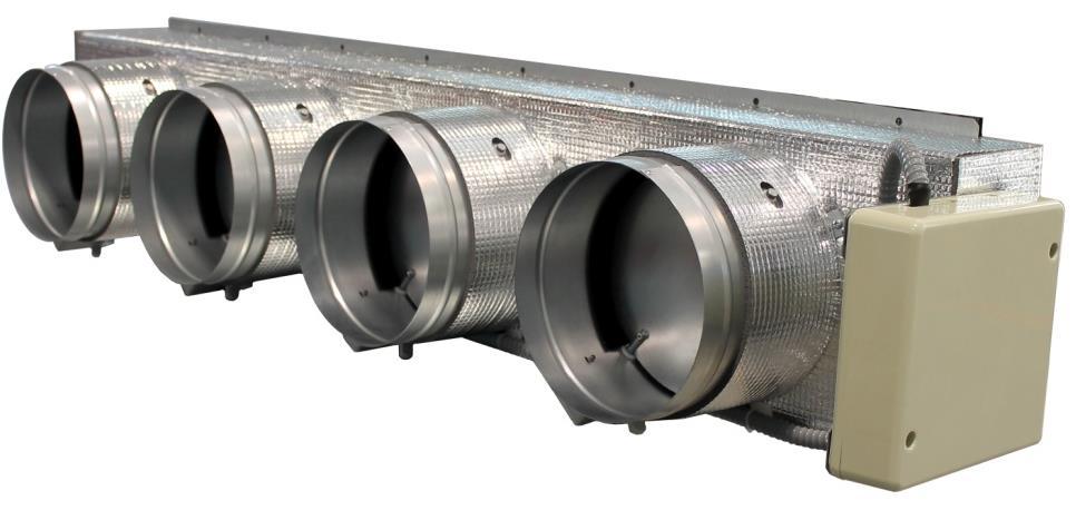
8 2. SYSTEM DESCRIPTION Daikin Zoning Kit, DZK is an optional kit that increases the flexibility of the FXMQ and FBQ Indoor Unit fan coils. It allows multiple separate ducts to be connected to fan coil and supply air to different individually controlled zones in a building Product Range DZK Zoning Box DZK030E5 12-O1/4 hole 5 X 5-7/8= 29-1/2 10-7/16 9-5/8 9-5/16 O 7-11/ / /16 4-5/8 10-7/16 DZK030E4 12-O1/4 hole 5 X 5-7/8= 29-1/2 O 10-1/4 9-5/8 9-5/ / / /16 4-5/8 10-7/16 8


9 DZK048E6 16-O1/4 hole 7 X 5-7/8= 41-5/ /16 9-5/8 9-5/16 O 5-11/ / /16 4-5/8 10-7/16 DZK048E4 16-O1/4 hole 7 X 5-7/8= 41-5/ /16 9-5/8 9-5/16 O 7-11/ / /16 4-5/8 10-7/16 DZK Zoning Box B. Motorized Damper A. Damper limitation adjustment A B 1:12.5 9


10 2.2. DZK Control DZK Control Board This device manages all wired and wireless devices in the system, performing the following functions: Controls and manages the status of each thermostat or controller. Outputs for the motorized dampers. Control of the auxiliary heat (up to two stages). Manages communication with the DAIKIN Interface Board. Controls the On/Off status, mode, fan speed, and set point temperature of the DAIKIN Indoor units Daikin - Interface Board This unit integrates the Daikin Indoor unit with the DZK control board. The Daikin interface board includes an Energy Efficiency Control Algorithm that is controlled with the Wired Thermostat, including the following functions: Automatically changes the Indoor Unit operation mode (Stop, Ventilation, Cooling, Heating, or Dry) from the in the DZK system s Wired Thermostat. Temperature setting for the AC unit based on the overall demand of the DZK zone thermostats. Defrost function: In heating Mode, when User Set Point Temperatures are satisfied, instead of setting the Daikin unit to OFF, a 60F set point Temperature is set. This function is set by means of DIP-switch configuration. 10
. When configured as master, operation mode selection for the system (Stop, Cool, Heat, Auto, Emergency heat, Dry). Sleep Function.")

. 2.2.5. DZK BACnet Interface board (optional) The DZK BACnet Interface board allows a Building Management System to control all variables of the DZK systems.")
11 Wired Thermostat Graphic color touch pad display for control of zone temperature master thermostat. Wall mounted. Graphic interface with 3 languages (Spanish, English, and French). Zone On/Off. Set point temperature setting (steps of 1ºF). When configured as master, operation mode selection for the system (Stop, Cool, Heat, Auto, Emergency heat, Dry). Sleep Function. (Only in DZK version 1) Eco-Adapt. Time schedule programming and, when configured as master, operation mode scheduling. Remote zone control. Used to set system parameters Wireless Thermostat This is a battery powered, wall-mounted, and back-lighted monochrome LCD touchpad digital thermostat to control the zone temperature. Zone On/Off. Set point temperature setting at steps of 1 ºF. Sleep Function. (Only in DZK version 1) Remote zone access. Local ventilation. Time schedule control. Powered by two 1,5V batteries (type AAA; included) DZK BACnet Interface board (optional) The DZK BACnet Interface board allows a Building Management System to control all variables of the DZK systems. The DZK BACnet Interface board uses a standard open protocol based on ASHRAE Standard 135, and its objects are: - Compatible with BACnet (ANSI /ASHRAE-135) - Compatible with BACnet/IP (ISO ) The DZK BACnet Interface board is a Plug&Play device for DZK, and it allows controlling and monitoring the following variables: Indoor Unit status. Fan status and Fan Speed. Auxiliary Heat stages status. Global Ventilation status. 11
 Activated/deactivated. Unoccupied Mode Status. Vacation Mode Activated/deactivated. Opening Damper Status for each zone. Indoor Unit and DZK errors. 2.2.6.")
12 Operation Mode. On/Off for each zone. Set point setting for Cooling and Heating for each zone. Room Temperature in each zone. Local Fan activated/deactivated for each zone. Auto (scheduling) Activated/deactivated. Unoccupied Mode Status. Vacation Mode Activated/deactivated. Opening Damper Status for each zone. Indoor Unit and DZK errors Heat Pump Changeover Master (Only in DZK version 1) Mode synchronization module for VRV Heat Pump installations with multiple indoor units. Power Connection to be wired from the Zoning Box control Board. To be mounted on damper number #1 in the Zoning Box. Synchronization module for Heat Pump installations with multiple indoor units with DZK Zoning box. Heat Pump Changeover Master controls up to 16 DZK systems in the same VRV system. 12


13 3. DESCRIPTION, INSTALLATION AND CONNECTION OF THE COMPONENTS 3.1. General recommendations Closely follow the instructions on this manual to avoid installation and maintenance issues. The system should only be installed by qualified personnel. Never use solid wire to install the system. This is a communication device and requires the use of communication cables. While connecting the devices, be sure the system is not powered. Follow the local installation regulations for low and high voltage installation. The recommended specifications for the cable to install this system are: o 4 wires o Stranded o AWG 20 o Plenum o Shielded When connecting to other systems fed with high voltage, only use the A and B contacts of the communication bus. It is not recommended to connect the + and contacts, nor the ground. Follow the color codes and polarity indications in the system components. Do not run the bus cable near high power cables or near electrical motors to avoid electromagnetic interference in the system communications. Use the following recommendations to locate the thermostat: h= 5 ft 13
14 To open the thermostat in preparation for its installation, it is recommended to use a coin. Using a screwdriver of other Sharp tool can damage the frame and the electronic components of the thermostat. If upon receiving the unit it is determined that one of the outlets will not be used, take the following actions: 1) Install the unit and wiring ready to start with the Wired Thermostat Configuration. The unit should have all dampers open. 2) Configure the Wired Thermostat. Once the thermostat is assigned a zone, all other dampers will close with the exception of that assigned to the Master thermostat. 3) At this time, disconnect the motor cable from the outlet that will not be used. 4) Permanently seal the outlet using the supplied plug and follow the local installation recommendations DZK Zoning box Assembly The Zoning Box allows providing a fast and simple zoning to Daikin indoor units FBQ_P and FMXQ_P. Models FBQ PVJU FXMQ PBVJU FBQ PVJU FXMQ PBVJU Damper Size Number of Dampers Keep in mind Make sure that the zoning box is in its correct position. (Actuators at the bottom) Follow the steps listed below to make an easy and reliable DZK installation: 1. The adaptor is shipped with the dampers fully open. One of them includes a plug to be used in case one of the dampers is not used. If the damper is not used, the contractor needs to be sure that the plug will stay in place. If all dampers are used, take the plug out and store it. 14
15 2. Insert sharp pointed object through the frame holes and the frame sealing to facilitate the location of the setting holes used to assemble the zoning box to the indoor unit. 3. Remove the indoor unit collar. Insert a screw (not fully tightened) in the bottom corners of the indoor unit as how in the following figure: 4. Sit the zoning box on the screws as shown below, and then affix the box using the left screws. 5. Attach each zone duct with its assigned damper. Follow the local recommendations to insulate and seal the ductwork with the damper. Make a cutout along the duct to keep the motor outside of the insulation. 15

 Damper is closed Check that the power cable is disconnected for the damper motor that will not be used.")
16 6. Use of the insulated stopper. If a damper is not being used in the installation, proceed as follows: Make sure the damper is closed before installing the insulated stopper. (The damper will close as soon as the first zone is assigned.) Damper is closed Check that the power cable is disconnected for the damper motor that will not be used. Power cable is disconnected Check that the damper remains airtight with the power ON and the fan running. Damper is closed 16


17 Damper setting The dampers included in the zoning box has a built-in control system that allows you to manually set the maximum and minimum opening of each damper according to the needs of each installation. Keep in mind This setting must be done after all dampers are assigned to their thermostats. REG lever Average Flow (REG) Due to the unique characteristics of each ID unit supply port with respect to the dampers of the box, the flow distribution is not identical in each damper. The central dampers receive more airflow than the others, being the damper No. 1 the one that receives less flow. This zoning box offers maximum aperture adjustment which balances the flow of each damper to the needs of the installation. By default, the dampers are configured with a maximum opening at Position I. To adjust the control of the dampers proceed as follows: Average flow adjustment lever The damper must be completely closed to mechanically adjust its flow. To make this adjustment create demand in all zones, so that the indoor unit runs at maximum capacity. Then deactivate the zone to be adjusted, and verify that there is no air supplied to that zone. With the damper closed, place the lever marked REG in the actuator to the desired open position. There are 4 position - I, II, III, and IV, with position I being completely open and position IV having the slightest opening. Perform the setting of the dampers by changing the lever REG position, beginning with the central one and ending with damper No. 1 (Closest to the zoning box control board). The reduced flow in the central dampers will increase the flow of the dampers at the ends. 17

18 Using an anemometer verify that the flow in each grille is within the installation requirements. Minimum Air (A-M) Similarly, the zoning box allows a minimum air opening for each damper, if needed. By default, the a damper is configured in the full-close position. To adjust minimum air for any damper, proceed as follows: A-M lever Check that the dampers are wide open to start its control. To do so, set the system to STOP mode, from the Wired Thermostat. Perform the setting of the dampers by changing the lever A-M position beginning with the one in the centre of the box and ending with damper 1. (Closest to the zoning box control board). Reduced flow in the central dampers will increase the flow of the dampers at the ends. With the damper open, place the handle A-M in the desired open position. It has 4 positions - a, b, c, d, where "a" is fully closed and is "d" is the fully open. Check with an anemometer that the flow in each grille is within the installation requirements. Minimum air adjustment lever 18


19 Connection Ref Function 1 Power supply 2 Heating Stage 1 Output 3 Heating Stage 2 Output 4 Protection probe input Alarm input (NC) 6 Actuator Control output 7 Daikin Interface Board 7 8 Expansion bus Wireless Interface 10 Reset System Button Connector for optional BACnet interface board 1. - Power supply Power supply 120/230 VAC line. The Zoning box control board is protected by a self-resettable fuse. This is an electronic component that does not require any action other than cycling the power to perform the reset Heating Stage 1 Output If the system includes Auxiliary Heat, when required by the heat demand, this output enables the First Stage of Auxiliary Heat. The technical specifications for the 1 st Stage Aux. Heat relay are: Imax. =1 24V, dry contacts. If higher power is required for control, use external contactors of appropriate capabilities. 19
20 3. - Heating Stage 2 Output This output enables Second Stage of Auxiliary Heat, if the system includes two stages Auxiliary Heat. The technical specifications for the 2 nd Stage Aux. Heat relay are: Imax. =1 24V, dry contacts. If higher power is required for control, use external contactors with appropriate capabilities Protection probe Input This input is used to connect the supply temperature sensor Alarm input (NC) When this input is open it will stop the AC unit, and close all dampers. This input is shipped with a jumper in the connector that should be left in place unless an alarm input is connected Actuator control outputs These outputs are used to drive the damper actuators with 12VDC control for each damper, as shown in the following diagram: 20

21 7. - Daikin Interface Board This Interface provides the communication between Zoning box control board and Daikin Indoor unit, connecting to P1 P Expansion Bus The expansion bus allows the connection of up to 6 Wired Thermostats. There are 3 connectors, each one with 5 contacts available, for connecting the expansion bus. The Wired Thermostat is connected to this bus (Maximum of 2 Wired thermostat per connector). Connect the cables to the connector contacts following the color code indicated below. Important: Its necessary one wired thermostat for each DZK system, which can control up 6 zones. Keep in mind Once this sequence is started it cannot be interrupted and the Quick Setup process should be allowed to finish Wireless Interface This device provides the communication between the Zoning box control board and the Wireless thermostats Reset System Button If the whole system needs to be reset (normally a replacement board that has been used before, or at the request of the technical support as a last resource to fix a problem), press and hold SW1 until LED 19 stops flashing. A system reset will return all configurations to default values and conditions. 21
22 11. Connector for optional BACnet Interface board In DZK version 2, the DZK BACnet Interface board allows the communication between the DZK zoning box and BMS BACnet/IP installation. In DZK version 1, the HP Changeover Master interface allows the communication between the HP Changeover Master interface and the DZK systems in a multiple indoor units installation. There is one connector with 5 contacts to connect the communication bus. This connector only supports the daisy chain configuration. Connect the cables to the connector contacts following the color code indicated below Daikin Interface Board Connection & Configuration Complete the connections adhering to the following steps, in this order: 1) Disconnect the power supply from both the Daikin Indoor unit and the DZK system. 2) Open the protective cover of the Daikin Indoor unit, and locate the P1, P2 connection (to which the Daikin navigation controller is connected). 3) Connect a two-wire cable to P1 P2 on the Indoor unit, in parallel with the Daikin navigation controller. 22
 Close the Daikin Indoor unit s protective cover. 3.4. DZK BACnet Interface board 3.4.1.")
23 Connect the other end of this cable to the connector labeled P1 P2 on the interface unit mounted on top of the control board, maintaining the polarity. 4) Close the Daikin Indoor unit s protective cover DZK BACnet Interface board Installation The DZK BACnet Interface board is a Plug&Play interface, disconnect the terminal and snap the connector and the interface support tube as shown in the pictures: System ID To configure this parameter, see on page 33. Note: This BACnet/IP device is connected to BMS by Ethernet cable. 23

24 BACnet typical layouts is a follow: DZK BACnet Interface board DZK BACnet Interface board configuration When the DZK BACnet Interface board is connected in the DZK main board, a new item appears in the installer configuration menu, as follows: From the main screen, press the icon and select the option Settings. In this menu select Configuration, a pop up warning message appears to alert you that it is exclusive for installers. Enter the pattern below to access the configuration menu. Select the option BACNET. Note: Check with the BMS vendor what device ID should be used to avoid conflict within the BACnet network. ID Device BACnet For the proper identification in the LAN of the DZK BACnet Interface board, it is required to modify the ID device, form the wired thermostat in the BACNET menu. By default the ID device is Note: Device ID is unique per BACnet device. 24


 - IP Address - Subnet mask")

25 Note: Check with BMS vendor what device ID should be configure here to avoid conflict within BACnet network. IP Configuration For the proper operation of the DZK BACnet Interface board with the IP network, it is required to configure the following network parameters: - Port (default 47808) - IP Address - Subnet mask - Gateway IP To configure them, you must access to IP Configuration menu, from BACNET menu:
 3.5.1.")
 to the rest DZK systems. Heat Pump Changeover Master controls up to 16 DZK systems.")

26 3.5. Heat Pump Changeover Master (Only in DZK version 1. In version 2, this functionality is managed by the Daikin interface board and the VRV system. For more details see DZK ZONING BOX Sequence of Operation document) Installation Heat Pump Changeover Master is a synchronization module for VRV Heat pump installations with multiple indoor units with DZK Zoning box (for VRV Heat recovery is not necessary). The operation mode is set by the DZK master system (System ID: 1) to the rest DZK systems. Heat Pump Changeover Master controls up to 16 DZK systems. The DZK Master system (System ID: 1) must be connected to the Indoor unit with the remote control configured as the system Master. Install the module on the damper #1 of the DZK master system as shown in the following pictures: Wiring The wiring should not exceed 130 ft. Stranded AWG20 shielded cable should be used. Connect the Heat Pump Changeover Master module with the interface on the DZK Master system. Use a 4 wire shielded cable, stranded, and plenum rated, when required. Connect the cable from the DZK Master System to the rest of the DZK Zoning systems to be controlled by the Heat Pump Changeover Master module. Connect only the communication wires A & B contacts. 26
27 AWG 20 2 wired System ID To configure this parameter, see on page 33. *SYSTEM ID: 1> Master System *SYSTEM ID: 1> Master System *SYSTEM ID: 2 to 16> Secondary System 27

28 Changeover Master Configuration Once the installation is finished and the Zoning Box configured (System ID): Verify that the Zoning Box connected to the Heat Pump Changeover Master module is configured as System ID: 1. Configure the other Zoning Box as System ID between 2 to 16. When the System ID configuration in all DZK systems is finished, wait 5 minutes to complete the update process Wired Thermostat Installation The Wired Thermostat is available for wall mount. The wiring should not exceed 130 ft, and stranded AWG20 shielded cable should be used. To mount the thermostat on the wall, take the following steps: Disassemble the thermostat in three parts. To split the frame from the base, use the edge of a coin. Do not use any sharp object. Affix the wall plate to the wall using screws and anchors according with the wall material. Insert the cable to the middle plate, and reassemble it to the wall plate. Reassemble the front frame to the base Wiring 28

29 DZK thermostats are connected to the expansion bus. The wall mounted thermostats are wired to the screws located in the middle frame. Be sure to connect the cables according to the engraving in the middle frame. Language -Press the value to select. -Press value. Zone ID -Press the value. -Press value. to confirm the to change to confirm the Zone subordinate - Press NO to change the value. - Press to change the subordinate zone. - Press to return to previous menu. - Press to confirm the value Wired Thermostat Configuration 1) Language You may select one of the three languages available for the interface. Español English (Default) Français 2) Select Zone It is now required to define the zone number associated with this thermostat. Each zone is associated with a control outlet. Zone 1 controls damper 1, zone 2 controls damper 2, and so on for up to 6 zones in the system. 3) Zone subordinate (subordinate damper) If needed, the system allows associating more than one damper with a single zone. This allows managing dampers from the thermostat that is being configured. Select No if there is no need to associate an additional damper with a zone. Select Link if one or more additional dampers are needed for a zone. Repeat this process to associate the outlets as needed. The screen will indicate the number of subordinate dampers associated with the zone. 29
30 Thermostat type Each DZK system must have one Wired Thermostat configured as Master. The thermostat s capabilities are determined by how it is configured: Master thermostat: Controls the system and zone parameters, operation mode, Time schedule programming, and AC configuration. Zone thermostat: Controls the local temperature and activation/deactivation of scheduled temperatures, and local ventilation. Thermostat Type - Press to change the value. - Press to confirm the value. Given that only one thermostat can be configured as Master, this parameter will not appear for selection if one thermostat in the system was already configured as Master. Thermostat reset: If there was some error in the initial configuration process and it is required to make changes, follow the steps described on page Wireless Thermostat Installation Wireless thermostats are only available for wall mount. The maximum distance between the Zoning box control board and the wireless thermostat in clear line of sight is 164 ft (50m). To mount the thermostat on the wall, take the following steps: Disassemble the thermostat in three parts as shown in the following figures. To split the frame from the base, use the edge of a coin. Do not use any sharp object. Affix the wall plate to the wall using screws and anchors according with the wall material. Reassemble the front frame to the base as shown in the following figure: Important Perform the pairing of thermostat in their final location. Distances less than 18 inches between the thermostat and the control board can saturate the receivers and make the pairing impossible. 30

31 Wireless Thermostat Configuration Before installing a Wireless thermostat, install the batteries in the thermostat. To activate Zone search From the Home Screen of Wired Thermostat: - Press to access Configuration menu. - Press Settings. - Press Configuration. - Press Enter on the advertisement screen. - Press Zone search to access. - Press On to activate. - Press to confirm the value. When you finish the association, turn it OFF to close the zone search. Zone ID - Press to change the value. - Press to confirm the value. 1) Zone search In order to pair the thermostats in the system, it is first necessary to open the pairing protocol process. To open this protocol, you must activate the zone search. After initiating the pairing sequence, it will remain active for 15 minutes to pair all thermostats. The Wireless Thermostat will display the letters. Press and hold the icon until the zone selection menu displays. 2) Zone selection In this stage the zone number has to be assigned to the thermostat. Each zone corresponds to a zone damper. The default menu displays the lowest available zone number. The menu displays the zones that are not assigned to other thermostats. If the menu displays, all zones are associated and there are not any free zones. 31
32 3) Subordinate damper The system allows a zone to be associated with more than one damper, if needed. This allows the control of several outlets from the same thermostat. -. (Default) This option indicates that no subordinate damper is required to be associated with the zone. Subordinate Damper - Press to change the value. - Press to return to previous menu. - Press to confirm the value. -. If more than one damper is required, then the thermostat will display the first damper number available for association. Repeat this process to associate the dampers that are needed. At the top of the specific thermostat, a display indicates the number of dependent dampers associated to the zone. Thermostat reset: If there was some error in the initial configuration process and changes are required, follow the steps described on page
33 4. ADVANCED CONFIGURATION 4.1. Wired Thermostat Wired Thermostat Configuration Menu Besides the quick configuration menu, the system has a number of configuration parameters to complete the installation. To access Configuration menu: From the Home Screen of Wired Thermostat: - Press to access Configuration menu. - Press Settings. - Press Configuration. - Enter the pattern. To access the configuration menu of the Wired thermostat, from the main screen, press the icon and select the option Setting. In this menu select Configuration, a pop up warning message appears to alert you that it is exclusive for installers. Please, enter the pattern below to access the configuration menu: Keep in mind - Press the parameter to change or be selected. - Use to select the value. - Press to confirm. - Press to go back or exit to previus menu. - Press to return to main menu or Home Screen. Link When you confirm a Link, the value displayed is the next available zone. System ID: (Only set in Heat Pump Changeover master installations) This option allows the installer to define the number of this DZK system within the whole installation. By default the value is 1. The system displays the free address values with a maximum value of 16. *Note: If you have a BACnet interface board, this parameter is not displayed and the address of the system is 1. Zone ID: This option displays the address associated with the zone of the thermostat. Wired Thermostat reset: If the value 0 is selected it will reset the thermostat and damper associated, leaving them free for a new configuration. The thermostat returns to the first screen where the association process can begin again. Subordinate: It shows secondary control dampers associated with this thermostat. You have the following selection options: - Look up: Displays the secondary dampers associated to the thermostat. Use to display the associated zones. If NO is displayed, this thermostat has no associated secondary control dampers. 33
34 - Link: Allow associate secondary dampers to the thermostat. Press Link to activate this option. Use to select the dampers to associate and then press to confirm. Repeat this process to associate the dampers required. If NO is displayed, no available zones are available to associate. - Release: Release a secondary damper associated to the thermostat. Press Release to activate this option. Use to select the damper to associate and then press to confirm. If NO is displayed, there is no secondary damper associated to release. Keep in mind - Press the parameter to change or be selected. - Use to select the value. - Press to confirm. - Press to go back or exit to previus menu. - Press to return to main menu or Home Screen. Thermostat type: This option shows whether the Wired Thermostat is configured as Master or Zone. Temperature SP range: This menu allows you to change the maximum set point temperature for heating mode [86ºF - 66ºF] and minimum temperature in cooling mode temperature [64ºF - 78ºF]. If you want to disable any of the modes, select OFF and the mode will be disabled for the user. By default the system has the maximum temperature in 86ºF for heating and minimum temperature of 64ºF for cooling. Air flow: This menu allows you to enable or disable the modulating system dampers. Proportionality graduated in four steps, the opening or closing of the damper is based on the demand for zone temperature to adjust the flow rate. By default the dampers are set for On /Off. To activate the modulation, press Modulating and confirm. The next screen will request to enter the Damper position. Enter the position of the Air flow adjustment - Average Flow lever of each damper to ensure the correct operation of the modulating functionality. - Press on the damper to configure. - Select the REG Lever. Repeat this process for all and each dampers and confirm with the right arrow. When confirming a new screen with a summary of each damper position will come up. If everything is correct, confirm again. Airflow This parameter applies to all motorized dampers in the system. Damper Position To know about Air flow adjustment - Average Flow. See on page
35 Keep in mind - Press the parameter to change or be selected. - Use to select the value. - Press to confirm. - Press to go back or exit to previus menu. - Press to return to main menu or Home Screen. Supply temp: This option allows the system demand to be ignored if the supply temperature exceeds a certain limit. The system selects as cutting heat temperature ºF. By default the system will cut the heating when the temperature reaches 129ºF. Zone search: This option allows you to open wireless channel association for connecting Wireless Thermostat to the Zoning box control board. - On: The wireless channel is open for 15 minutes. - Off: The wireless channel is closed. Disable program: The system allows you to disable the time schedule programming functions and enables Sleep Mode (Only in DZK version 1) in the zone for the user. - On: The time programs and sleep mode are enabled. - Off: The time programs and sleep mode are disabled. Information: This option provides useful information in the system: - Ambient temp: Displays room temperatures for each of the zones in a system. Select the zone you wish to display using. - Devices: Provides a detailed list of the various devices installed in the system: Wireless thermostats, wired thermostats, Wired Thermostat (Graphic TT), Gateway (board-enabled Daikin interface), and wireless channel. - Firmware: The information displayed for the system check: Wired Thermostat and Zoning box control board firmware. Q-Adapt: This option allows the user to select the system velocity map adequate for the installation. The available options are: - Q-Power: Promotes increased flow in the velocity map. - Q-Standard: Default configuration. - Q-Silence: Noise reduction. - Q-Minimum: The indoor unit fan coil works at minimum speed. - Q-Maximum: The Indoor unit fan coil works at maximum speed. 35
36 Offset: This option allows the user to apply an offset to the room temperature reading. The offset range goes from -5 F to +5ºF. The default value is 0ºF. This offset will be applied immediately on the room temperature of the zone. Weight: With this option you can set the weight of the zone. The weight of the zone will be used for calculating the mode (autochange over) or for calculating heat demands if auxiliary heat. It is an indicator of the size / importance of the zone. Possible values range from The default value is 100 / Number zones. Setback: Unoccupied time schedule programming is determined by two settings: - Disable: If the default demand temperature is surpass by the differential defined, the area will cease the demand. Range: 2ºF to 7ºF. By default 4ºF. - Override Time: Is the time that the zone will enter in occupied mode when the user touches the thermostat screen during an unoccupied period. [10-120] minutes, 60 minutes by default. Auxiliary Heat: The operation of auxiliary heat is influenced by several parameters: - Auxiliary heat (1) o Defines how many stages of auxiliary heat a system has. Possible values are 0, 1, and 2, with a default of 0. 0: There is no auxiliary heat. The system works only with the heat pump. If set to 0, Emergency Heat mode will not be available. 1: One-Stage Auxiliary Heat. 2: Two-Stage Auxiliary Heat. o First Supply Heat. If the setting for Auxiliary heat is 1 or 2, then the first system to supply heat must be defined as either: Heat Pump. Aux. Heat. Note (Only in DZK version 2): If the auxiliary heat is electrical and the installation is heat pump type, then the first to supply heat must be Heat Pump in the DZK master system. Note (Only in DZK version 1): If the auxiliary heat is electrical and the installation has a Heat Pump changeover master, then the first to supply heat must be set to be the Heat Pump. Keep in mind If the setting is not confirmed with the continue button, the new setting will not be saved. 36
37 Auxiliary Heat (2) Only displays if One/Two Stage is selected. - Auxiliary Heat (2), Fan Configuration: In the second screen configuration, there are the following parameters: o Heating device: Defines if the ID unit fan must be active during the auxiliary heat operation. Electric (Fan ON) Furnace (Fan OFF) o Fan delay (sec): Defines the delay time (in seconds) to turn off the fan. Possible values are 0, 45, 60 and 120. Auxiliary Heat (3) Only displays if One/Two Stage is selected. - Auxiliary Heat (3), First Stage Activation: the user must define three parameters: o First Stage Differential: Temperature the system has to surpass to activate the first stage of auxiliary heat. Values [2-10] ºF, by default 2ºF. o First stage hysteresis: Defines the hysteresis for the operation of the first stage. Range: 1ºF to First Stage differential value still 6ºF at maximum. By default 1ºF. o Min time exhausted: Minimum time that the Heat Pump must be active before the first stage of auxiliary heat can be activated. Values [0-120] minutes, by default, 30 minutes. Auxiliary Heat (4) Only displays if Two Stages are selected. - Auxiliary Heat (4), Second stage activation: the user must define three parameters: o Second stage differential: Temperature the system has to surpass to activate the second stage of heating. Values [2-10] ºF, by default 2ºF. o Second stage hysteresis: Defines the hysteresis for the operation of the second stage. Range: 1ºF to Second Stage differential value still 6ºF at maximum. By default 1ºF. o Minimum time exhausted: Minimum time that the first stage must be active before the second stage of auxiliary heat can be activated. Values [0-120] minutes, by default, 30 minutes. Autochange: This option of the configuration menu, the user sets the three values that define the operation of the auto-changeover. - Set point Differential: Minimum differential between heating and cooling set points. 37
38 For example, if set 2ºF, the system will force the cooling set point at least two degrees higher than the heat. Values [0-7]ºF, by default 2ºF. - Mode Switching Protection: Minimum run time before allowing a mode change. Values [15-90] mins, by default 30 mins. - Heat OVR Temp: If a zone has a higher heat demand than this temperature, the system reverts heating operation, even though the cooling global demand exceeds the heat demand. Possible values are: Not applicable, [3 to 8] ºF in steps of 1ºF. Default value: Not applicable. BACNET: This parameter displays the ID Device, the uplink port, the IP address, the subnet mask and the Gateway IP and allows you to modify them. Press on the value you want to change, modify it and then press to confirm. The values by default are: - Port: IP Address: Subnet Mask: Gateway IP: Note: In case of system reset, it will return to default values. Keep in mind - Press the parameter to change or be selected. - Use to select the value. - Press to confirm. - Press to go back or exit to previus menu. - Press to return to main menu or Home Screen Interface Menu This menu allows the user to modify several options related to the Wired Thermostat controller interface. Brightness Select the screen brightness for both active modes. Select the standby mode (Off or Bright). Date & Time Select Date: Select current day, month and year. Select time: Select current time. Select a 12-hour (AM/PM) or 24-hour time format. Enable or disable daylight savings. Language Select among 3 languages: Español English (default) Français To access Interface menu From the Home Screen of Main Thermostat: - Press to access Configuration menu. - Press Settings. - Press Interface to access. 38
39 Keep in mind - Press the parameter to change or be selected. - Use to select the value. - Press to confirm. - Press to go back or exit to previus menu. Vacation Press on the value to change. Global ventilation When global ventilation is activated, the icons are displayed on the home screen as follows: Stop Heat Cool Dry Local ventilation Not available for the Operation Mode and global ventilation enabled Beeping Select the beeping sound mode: Sound ON (default) Sound OFF User Settings On this menu the user will be able to configure some parameters: Units Select temperatures to be displayed: ºC (Celsius) ºF (Fahrenheit) Vacation The Vacation mode feature helps you conserve energy while you are away for extended periods of time. Select type of Vacation mode: System. Active (On) or deactivate (Off) vacation mode to all zones in the system. Zone. Active (On) or deactivate (Off) vacation mode to the current zone. Display the set temperatures: o Heat. Select ºF. (In DZK version 1 select ºF) o Cool. Select ºF. (In DZK version 1 select ºF.) Global Ventilation Global Ventilation allows to activate the ventilation in all zones system during the system inactivity periods. Select Status. NO: Disables Global ventilation. YES: Enables Global ventilation. o Every (mins). Length of the interval between periods of ventilation. (In minutes) o Run for (mins). Duration of ventilation. (In minutes) Local Ventilation Local ventilation allows activate the ventilation in the Wired Thermostat zone during the system inactivity periods. Select Status: On: Enables Local ventilation. Off: Disables Local ventilation. Important: In Heat Pump installations, it is recommended not to activate the global and local ventilation in a DZK zoning box connected to the master indoor unit. It may impose the Stop mode to the rest of the DZK zoning box. 39
40 4.2. Wireless Thermostat Access to the Configuration Menu To access the advanced setup menu, the Wireless Thermostat must be off by pressing the ON/OFF icon. Press the screen Press the On/Off icon - On the Home Screen, press the icon until the test screen icon is displayed. - Upon releasing the icon, the zone temperature will be displayed. - At this time, press and hold again the icon until the first parameter is displayed. From this menu, press to return to the stand-by screen. Keep in mind - Press to access to the menu. The value is blincking when it is enable to edit. - Press to go back. - Press to select the value. - Press to edit a value or confirm Configuration Menu Besides the quick configuration menu, the system has a number of configuration parameters required to complete the installation. The following configurations are available: Zone ID: This option displays the address associated with the zone of the thermostat. Wireless Thermostat reset: If the value is selected, the thermostat and its associated damper(s) will reset, freeing them for a new configuration. The thermostat then returns to the first screen to allow you to start the association process again. 40
41 Keep in mind - Press to access to menu. The value blinks when editing is available. - Press to go back. - Press to select the value. - Press to edit a value or confirm. Look Up If the screen displays when you access to menu, means there isn t secondary dampers associated. Link If the screen displays when you access to Link menu, means no secondary dampers available. Subordinate dampers: Show the dampers associated to the thermostat. Look up: Displays the secondary dampers associated to the thermostat. - Press to see all the subordinate dampers associated to current thermostat. The values begin blink. - Use the arrows to change values. If it displays, indicates that the thermostat has no damper associated to it. Link: Allow associate secondary dampers to the thermostat. The value then blinks. - Use the arrows to select. - Press to access link menu which then displays. Displays and the damper numbers available for association. - Use the arrows to select the value. - Press to confirm the value which displays. Repeat this process to associate the dampers you need. Press with value to end the association and the screen returns to the Look-up menu. Release: Release a secondary damper associated to the thermostat. The value then blinks. - Use the arrows to select the value. - Press to access the realese menu which then displays. Use the arrows to select to release or NO to cancel the release. - Press to confirm the value and return to the Look-up menu. 41
42 System information: This option provides useful information about the system. - Room temperature: This option displays room temperature for each zone. Press access. Use the arrows to navigate the room temperatures for each remote zone. - Radio Level: This option shows the receiving signal power in percentages. If appears in the screen, there is no radio reception. Keep in mind: - Press to access to menu. The value blinks when editing is available. - Press to go back. - Press to select the value. - Press to edit a value or confirm. - Battery level: Displays battery level of the thermostat in percentages. - Device s System: Provides a detailed list of the devices installed in the system: Wireless thermostats, Wired thermostats, Daikin interface, and wireless channel. To access, touch and use the arrows to navigate through the different devices. : Number of Wireless thermostats connected to the Zoning box control board. : Number of wired thermostats connected to the Zoning box control board. (N/A) : Wired Thermostat connected to the Zoning box control board. : Wireless communication channel. Between to. : When is displayed, the Daikin Interface Board is enabled on the zoning box control board. - Firmware: The information displayed for the system check such as the current thermostat and Zoning box control board firmware: : Zoning box control board firmware version. : Wireless Thermostat firmware version. 42
43 Keep in mind - Press to access to menu. The value blinks when editing is available. - Press to go back. - Press to select the value. - Press to edit a value or confirm. To User access From home screen: -Turn Off the room. -Short Press on to advance screen. Display *. - Long Press on. *Note: version 1. till display only in DZK Offset: This option allows the user to apply an offset to the room temperature reading. The offset range goes from - to +. The default value is. This offset will be applied immediately on the room temperature of the zone. Weight: With this option the installer can set the weight of the zone. The weight of the zone is used to calculate the mode (auto change) or to calculate the heat demands when the auxiliary heat is active. It is an indicator of the size/importance of the zone. Possible values range from-. The default value is zones User Settings This section describes how to configure user settings. Units Select temperatures to be displayed. -. Celsius -. Fahrenheit Vacation status The Vacation mode feature helps you conserve energy while you are away for extended periods of time. It also ensures your home is comfortable when you return. Select status: -. Enable -. Disable Vacation set point temperatures Select the set temperatures: - Heat. Select --ºF. (In DZK version 1 select --ºF) - Cool. Select --ºF. (In DZK version 1 select --ºF.) Time schedule programming disable The system allows disabling functionality for zone- scheduled temperature settings. To access the advanced setup menu the Wireless Thermostat zone must be off by pressing the ON/OFF icon. 43
44 Press the screen Press the On/Off icon On the Home screen, press and hold the highlighted area in the following figure to access. To confirm the change, touch the icon to select the new setting and once again to go back to the standby screen. Time schedule programming enable To enable this option, press and hold the highlighted area in the following figure to access the ON screen. To confirm the change, touch the icon to select the new setting and once again to return to the stand-by screen. 44
45 5. COMMISSIONING STEPS 5.1. Turn on power to all systems Wired Thermostat. Verify that the device boots up (square clock icon will display temporarily). After a few seconds the configuration screen is displayed. Configuration screen of the Wired Thermostat Main Control Board. Verify that the LEDs status is correct. Correct LEDs status Ref LED indication Normal status Color D1 Receive data from BMS (BACnet) connector Blinking Green D2 Transmit data to BMS (BACnet) connector Blinking Red D3 Control Board Internal Bus Activity Blinking Green D4 Transmit data in the expansion bus Blinking Red D5 Receive data in the expansion bus Blinking Green D11 Power supply Fixed Red LEDs status 45
46 Daikin interface Board. Verify that the LEDs status is correct. Correct LEDs status Ref LED indication Normal status Color D1 Daikin Interface board power supply Fixed Red D2 Daikin Interface board internal bus activity Blinking Green D3 Data transmission to the DZK system Blinking Red D4 Data reception from the DZK system Blinking Green D5 Data transmission to DAIKIN thermostat Blinking Red D6 Data reception from DAIKIN thermostat Blinking Green Wireless Thermostat. Verify the word is displayed on the screen. Wireless Thermostat during scanning 46
47 5.2. Communications with the Indoor unit Modes / Temperature Check that the Navigation Controller receives the operating mode change from the zoning system. To verify that, change the operating mode on the Wired thermostat and verify that the new mode appears in the Navigation Controller. DZK Wired Thermostat Daikin navigation controller Check that the Daikin thermostat receives the temperature changes from the zoning system. To do this, deactivate all thermostats but the Wired thermostat. Change the wired thermostat set point, and verify that the set point in the Daikin thermostat follows the specified set point changes. DZK Wired Thermostat Daikin navigation controller 47
48 5.3. Zone assignment Activate every thermostat, one at a time, and set it for demand by pressing Select mode > Remote zone (see the section Remote Zone Control from the User s Manual). Verify that the zone where the thermostat is located is receiving air. Change the set point to eliminate the demand, and verify that the airflow stops Q-Adapt level selection Check the change of the fan speed depending on the number of demand zones in the Q-Standard. Remember that the Q-Adapt function is available in the Main wired thermostat to adapt the velocity map according to the installation requirements. Nº Zones Zones calling demand 2 speeds indoor unit Q-Minimum Q-Silence Q-Standard Q-Power Q-Maximum 6 Low High High High High 5 Low High High High High 4 Low Low High High High 3 Low Low Low High High 2 Low Low Low Low High 1 Low Low Low Low High 5 Low High High High High 4 Low High High High High 3 Low Low High High High 2 Low Low Low High High 1 Low Low Low Low High 4 Low High High High High 3 Low Low High High High 2 Low Low Low High High 1 Low Low Low Low High 3 Low High High High High 2 Low Low High High High 1 Low Low Low High High 2 Low Low High High High 1 Low Low Low High High Fan speed depending on the number of demand zones 48

49 3 speeds indoor unit Nº Zones Zones calling demand Q-Minimum Q-Silence Q-Standard Q-Power Q-Maximum 6 Low High High High High 5 Low Medium High High High 4 Low Medium Medium High High 3 Low Medium Medium Medium High 2 Low Low Low Medium High 1 Low Low Low Low High 5 Low High High High High 4 Low Medium High High High 3 Low Medium Medium High High 2 Low Low Medium Medium High 1 Low Low Low Low High 4 Low Medium High High High 3 Low Medium High High High 2 Low Low Medium High High 1 Low Low Low Medium High 3 Low Medium High High High 2 Low Low Medium High High 1 Low Low Low Medium High 2 Low Low High High High 1 Low Low Medium High High Fan speed depending on the number of demand zones Check with an anemometer that the air supply to each zone is the desired amount. Verify the airflow with all zones open, and also individually with each zone open. Before adjusting mechanically the maximum opening (REG), ensure that the zone damper is closed. To do this turn off the zone to be adjusted while keeping any other zone calling demand (See User s Manual). Damper is closed Damper limitation adjustment 49
50 5.5. Other configuration parameters If the installation has Auxiliary Heat, verify that it is correctly installed and configured. Verify that the Operation Mode menu displays Emergency Heat as an option. Operation Mode menu If you use Auxiliary Heat check the relays operation in the zoning box control board to ensure it is working properly (first H1, then H2). To verify, set the system calling demand for heat and keep in mind that there is an activation delay. Turn the system off and verify that H1 and H2 are disabled. Auxiliary Heat connectors and indicators Ref LED indication Aux. Heat Status D6 D7 1st Stage Aux. Heat 2nd Stage Aux. Heat On Off On Off Relays operation of the zoning box control Normal status On Off On Off Color Green Green 50
51 6. EXCEPTION CODES In the event of Zoning system alerts, the system displays an error code on the home screen of the thermostat where the error is detected. If there is an alert originated by the Daikin Unit, the Wired thermostat displays an error text and an exclamation mark on the help icon until the problem has been solved. Review the message with the Daikin Unit documentation and solve the issue according to Daikin recommendations. List of DZK zoning box system alerts Your Wired Thermostat can generate the following alert messages: - Unoccupied. The Setback time program is active. If you touch on the Home screen, it will deactivate the setback program and return to occupancy set point during the override time. - Eco limit. The user has tried to exceed the Eco-Adapt temperature limit. If required, disable the Eco-Adapt to set the desired temperature. - Override. The override time is active. When the override time has finished, the system returns to its previous status. Vacation. The vacation mode is active. - DZK 1. Communication error between Wired/Wireless Thermostat and the Control Board. This error blocks the thermostat. Corrective actions: - Verify the status of the Zoning box control board. - Verify the connections and the wiring between the Zoning box control board and the Wired Thermostat. - Verify the radio communications between the Wireless Thermostat and the Zoning box control board. - Error 5. Remote temperature sensor assigned to the thermostat is open. - Error 6. Remote temperature sensor assigned to the thermostat is short circuited. 51
52 - Error 9. Air-conditioning communication error with the system. The system opens every motorized outlet and control from the air-conditioning controller is enabled. Corrective actions: - Verify the Daikin Interface board status. - Verify the wiring connection between the Daikin Interface Unit and the Daikin Indoor unit. Error 10 (Only in the Wired thermostat). DZK BACnet Interface board communication error with the system. Check the connection from the DZK BACnet Interface board to the main control board. Error 11 (Only in the Wired thermostat). Communication error between the AC indoor unit and the system. 7. AUTO DIAGNOSTICS 7.1. Zoning box control board The Zoning box Control Board has integrated LED s that provide information of abnormal conditions. Ref D1 D2 D3 D4 D5 LED indication Receive data from BMS (BACnet) connector Transmit data to BMS (BACnet) connector Control Board Internal Bus Activity Transmit data to Wired Thermostat Receive data from Wired Thermostat Normal Status Blinking Blinking Blinking Blinking Blinking Color Green Red Green Red Green D6 1 st Stage Aux. Heat Activated Fixed Green D7 2 nd Stage Aux. Heat Activated Fixed Green D10 Packet radio reception Blinking Green D11 Power supply Fixed Red D18 Wireless Thermostat associated Fixed Green D19 Radio link active Fixed Red 52
53 7.2. Daikin Interface Board Daikin s interface board has integrated LED s that provide information about abnormal conditions. Ref LED indication Normal Status Color D1 Interface power supply Fixed Red D2 Daikin Board Internal Bus Activity Blinking Green D3 Data transmission to Zoning box control board Blinking Red D4 Data reception from Zoning box control board Blinking Green D5 Data transmission to Daikin navigation controller Blinking Red D6 Data reception from Daikin navigation controller Blinking Green 1) Power Supply LED (D1) is not ON Verify the AC Unit Power Supply. Verify the correct connection between the Daikin Indoor unit and the Daikin interface board. 2) Microcontroller Activity LED (D2) does not blink Contact Technical Support. 3) Zoning box control board Communication LED s (D3/D4) does not blink Check the connection between the Daikin Interface board and the Zoning box control board. 4) Indoor AC Unit Communication LED s (D5/D6) do not blink Check the correct connection between the Daikin Indoor unit and the Daikin interface board. 53
54 7.3. BACnet Interface board The BACnet Interface board have integrated LEDs that detect unusual operations. Ref LED indication Normal status Color U3 Ethernet data reception Blinking Red U4 Ethernet data transmission Blinking Green U5 Automation bus data transmission Blinking Red U6 Automation bus data reception Blinking Green U66 Micro controller activity Blinking Green Ethernet connected Fixed Yellow Ethernet activity Blinking Green 1) All LEDs flashing It indicates the IP selected for the DZK BACnet Interface board is already being used by other device. Access settings (See on page 33) and change the parameter IP Address. 54
55 8. NAVIGATION GUIDE 8.1. Wired Thermostat navigation guide Note: Sleep mode only in DZK version 1. 55
56 8.2. Wireless Thermostat navigation guide Note: Sleep mode only in DZK version 1. 56
57 57
58 9. TROUBLESHOOTING Item Symptom Verification/Action Wired Thermostat does not light up Wireless thermostat does not work After a power failure, appears in the WTs The AC unit does not start even if everything is OK. After setting the mode to COOL, the Wired Thermostat shows STOP When accessing remote zones, one of them is not listed Verify the cable connection between the Wired thermostat and the Control Board. See on page 21. Never use solid wire for this connection. Verify that the elastic contacts in the base of the thermostat are securely fastened to the circuit board. To ensure this contact, slightly bend forward the contacts. See on page 28. Verify that the voltages between the + and contacts in the thermostat base are 12VDC. Se on page 29. The zone controlled from the wired thermostat cannot be remotely accessed. After 45 minutes, its damper(s) will open and remain open until the problem is fixed. From any other zone thermostat, accessing the remote zones by selecting will allow you to change the Operation Mode until the Wired Thermostat returns to normal operation. See the User manual. If the thermostat is replaced, only perform the initial configuration. All other parameters and settings will be recovered automatically from the Control Board. See on page 29. Verify polarity and power level of the batteries. See on page 31. The zone controlled from the wireless thermostat cannot be remotely accessed. After 45 minutes, its damper(s) will open and remain open until the problem is fixed. If the thermostat is replaced, only perform the initial configuration. All other parameters and settings will be recovered automatically from the Control Board. See on page 31. Reset the thermostat, link it up, and thereafter perform an initial configuration. The Wireless thermostats can take up to 5 minutes to update the screen. Touch the screen to force an immediate update. Verify that there is a jumper between the contacts of the Alarm connector. See on page 20. Verify that the Indoor Unit is powered on. Verify that the Daikin Communication LEDs D5 and D6 located in the Daikin Interface board mounted over the Control Board are blinking. See on page 53. Verify that the thermostat of the zone missing is working correctly. To this end, activate/deactivate the zone and check that the damper opens/closes correctly. 58
59 Item Symptom Verification/Action 6 The Wireless Thermostat displays all zones but its own LED D3 in the Control Board is not blinking LED D5 in the Control Board is not blinking On activating the zone, no air is supplied to its grille(s) if the fan coil is on One Wireless Thermostat shows permanently When trying to remote access other zones, the Wireless Thermostat will not display its own zone. Verify that the Control Board is powered. See on page 19. If the power LED (D11) is on, the Control Board is faulty. See on page 52. The board is not receiving information from the Wired Thermostat. Verify the wiring between the Wired Thermostat and the Control Board. See on page 21. Never use solid wires for this connection. Verify that the damper assigned to the thermostat is not blocked by the insulation stopper. See on page 16. Verify that the motor is electrically connected properly. There is a connection at about 4 inches from the actuator. See on page 20. Verify in the actuator connection indicated above, that when demand is created from the thermostat, there are 12VDC between the contacts indicated above. This voltage will be present for about 5 seconds. See on page 20. Verify that the zone assigned to the thermostat is the correct one. If it is not the correct damper, proceed to reset the incorrectly assigned thermostats (See on pages 33 and 40.) and reassign to the correct zones. (See on pages 29 and 31.) Ensure that the Zone Search is active, from the Wired thermostat. See on page 35. Verify that there are available zones. The number of available zones depends on the DZK model, despite that the thermostat can show up to 6. Verify if there is any zone that has a dependent zone. In the Remote Zone menu in the Wired Thermostat, verify which zones are installed. See the section Remote Zone Control from the User s Manual. Bring the thermostat closer to the DZK Zoning Box, and associate it with a zone. Once completed, take it back to its final location. If the thermostat shows or the signal power is too low, the distance to the control board is too great or there is too much radio interference. There are two possible solutions to this situation: Verify by moving the thermostat within the zone to see if it gets a good connection (remember to touch the screen to update it immediately), or install a wired Wired thermostat into a configured zone. 59
60 Item Symptom Verification/Action If one or more zones do not control the temperature Battery symbol is shown DZK 1 on the Wired Thermostat DZK 1 on the Wireless Thermostat () Error 5 on the Wired & Wireless Thermostat () Error 6 on the Wired & Wireless thermostat () Verify that the Operation Mode is not STOP. See Troubleshooting Point 4. Verify room and set point temperatures in the non-working zone thermostat to see if it is creating demand. Verify that the damper actuator is connected properly at about 4 inches from the actuator. See on page 20. Verify communications between the Daikin Interface Board and the Indoor Unit (LEDs D5 and D6 in the Daikin Interface Board). See on page 52. Verify that no ERROR number is shown on the screen. See on page 51. If D5 and D6 do not display normal behavior (constant blinking), verify the wiring between the Daikin interface Board and the Indoor Unit. See on page 22. When the battery icon is shown on the screen, there are about 15 days left to change the thermostat batteries. If the Zoning box control board has just been powered on, DZK 1 will display on the screen until the system completes its boot process (about 30 seconds). Verify that LEDs D4 and D5 are blinking, which indicates there is communication between the Control Board and the Wired Thermostat. See on page 52. Verify the connections and the wiring between the Zoning box control Board and the Wired thermostat. See on page 28. If the zoning box control board has just been powered on, DZK 1 will show on the screen until the system completes its boot process (about 30 seconds). Keep in mind that the wireless thermostat screen can take up to 5 minutes to update. However by touching its screen, it will update immediately. Verify the radio communications LEDs (D10) between the Wireless Thermostat and the Main Control Board. See on page 52. Remote temperature sensor assigned to the thermostat is open. Remote temperature sensor assigned to the thermostat is short circuited. 60
61 Item Symptom Verification/Action Error 9 on the Wired & Wireless thermostat () Error 10 on the Wired thermostat Error 11 on the Wired thermostat The dampermodulating functionality does not work as expected (Airflow >Modulating setting) The Heat Pump Changeover Master don t work properly (Only in DZK version 1) In Heat mode, when trying to change to Cool mode, the thermostat returns to Heat mode In Heat Pump installations, the DZK zoning box connected to a slave indoor unit, changes to Stop mode (Only in DZK version 2) Verify that the Indoor Unit is powered on. Verify the Daikin Interface board LEDs status. See on page 52. Verify the wiring connection between the Daikin Interface Unit and the Daikin Indoor Unit. See on page 22. Verify the DZK BACnet Interface board LEDs status. See on page 54. Verify the wiring between Daikin indoor unit and Daikin Interface board. See on page 22. Verify that the damper REG level is located as configured in the Modulation configuration parameter. See on pages 17 and 34. Verify that the Heat pump changeover Master is connected to the Zoning box master system. From the wired thermostat, check System ID. See on page 33. Verify the cable connection between the Heat pump changeover Master and the Zoning box master system (System ID: 1). See on page 24. Verify that the DZK Zoning box secondary have System ID: 2 to 16. From the wired thermostat, check System ID. See on page 33. Verify the cable connection between the Zoning box master DZK system (System ID: 1) and the secondary DZK Zoning box (System ID: 2 to 16). See on page 24. The operational mode in the installation is controlled by the Heat Pump Changeover Master. The operation mode can only be changed from the Wired thermostat of the Master DZK. (Only in DZK version 1) The operational mode in the installation is controlled by the Daikin master controller. The operation mode can only be changed from the DZK Wired thermostat connected to Daikin master controller. (Only in DZK version 2) This is caused by the incompatibility between the subordinate unit mode and the master unit. Check the master unit is not working on ventilation mode. See on page
62 Item Symptom Verification/Action The global ventilation does not work as 24 expected. There is no ventilation after all zones are satisfied (Only in DZK version 1) The local ventilation does not work as expected. There is no ventilation after all zones are satisfied (Only in DZK version 1) Defrost mode on the Indoor Unit don t work properly Verify if the installation is controlled by the Heat Pump Changeover Master. If that is the case, until all zones of all interconnected DZKs are satisfied, the global ventilation will not be activated. Verify if the installation is controlled by the Heat Pump Changeover Master. If that is the case, until all zones of all interconnected DZKs are satisfied, the local ventilation will not be activated. If the Daikin indoor unit has start/stop cycles in periods shorter than 30 minutes, set the dip switch #2 in the Dakin interface board to ON In the DZK BACnet Interface board, all LEDs are flashing The DZK system does not detect the BACnet Interface board The Interface for use in BACnet cannot be connected It indicates the IP selected for the DZK BACnet Interface board is already being used by other device. Access settings (See on page 33) and change the parameter IP Address. Verify that the LED U66 is blinking and LEDs U5 and U6 are alternately flashing. (See on page 54) If the above does not verify, check the correct connection of the gateway on the DZK control board, verifying the 4-pin connector. Verify that LEDs U3 y U4 (see on page 54) are blinking, and those in the Ethernet connector are active. If the above is not true, check that the Ethernet cable is properly connected. 62

63 Heat Pump Changeover Master module DZK-CM-1 4 wired AWG20 stranded shielded AUX Heat Dry contact (max 1 A@24) 2 wired AWG18 stranded no shielded Power supply cable Aux Heat Stage 1 Aux Heat Stage 2 DZK-CB-2 Power supply 120/240 VAC Wired Thermostat DZK-MTS-2-W P1 P2 to indoor unit PCB F1 F2 in-out VRV communication bus Wireless Thermostat DZK-ZTS-2-W P1 P2 10. WIRING DIAGRAM 63
 Aux Heat Stage 1 Aux Heat Stage 2 DZK-CB-2 Power supply 120/240 VAC Wired Thermostat DZK-MTS-2-W P1 P2 to indoor unit PCB F1 F2 in-out VRV communication bus Wireless Thermostat DZK-ZTS-2-W P1")
64 Daisy chain to other DZK units with DZK-BACNET-2 Network switch 4 wired AWG20 stranded shielded 2 wired AWG18 stranded no shielded Ethernet CAT4 cable Power supply cable AUX Heat Dry contact (max 1 A@24) Aux Heat Stage 1 Aux Heat Stage 2 DZK-CB-2 Power supply 120/240 VAC Wired Thermostat DZK-MTS-2-W P1 P2 to indoor unit PCB F1 F2 in-out VRV communication bus Wireless Thermostat DZK-ZTS-2-W P1 P2 11. WIRING DIAGRAM - BACNET/IP INTERFACE 64
65
66
67

68 Phone:
Installation Manual. Zoning Kit
 Installation Manual Zoning Kit TABLE OF CONTENTS Warnings, environmental policy, and certifications... 5 Warnings... 5 Environmental Policy... 5 FCC Regulatory Notices... 6 INTERTEK / UL Regulatory Notices...
RGR150 USER S MANUAL. Wireless Rain Gauge with Thermometer and Clock
 RGR150 manual-final-091908:layout 1 9/19/08 8:59 AM Page 1 RGR150 USER S MANUAL Wireless Rain Gauge with Thermometer and Clock INTRODUCTION Thank you for selecting this Wireless Rain Gauge. This device
Wireless Thermostat (WTS10) Keypad Operation Guide
 Keypad Operation Guide") Keypad Operation Guide This Guide is intended to provide basic instructions for operating the thermostat from its on-board user interface prior to it being commissioned into the wireless ControlScope network.
Keypad Operation Guide This Guide is intended to provide basic instructions for operating the thermostat from its on-board user interface prior to it being commissioned into the wireless ControlScope network.
WIRELESS TEMPERATURE & HUMIDITY STATION INSTRUCTION MANUAL
 WIRELESS TEMPERATURE & HUMIDITY STATION INSTRUCTION MANUAL MODEL: S82967 DC: 071118 FIND MANUALS, FAQS, AND MORE UNDER THE SUPPORT TAB HERE: www.lacrossetechnology.com/s82967 TABLE OF CONTENTS 3. Power
Pioneer Z100 Smart Thermostat Operating and Installation Manual
 Pioneer Z100 Smart Thermostat Operating and Installation Manual AW000515-B Page 2 Operating and Installation Manual Congratulations on the purchase of your new thermostat. It has been designed for easy
Pioneer Z100 Smart Thermostat Operating and Installation Manual
 Pioneer Z100 Smart Thermostat Operating and Installation Manual AW000286-D Page 2 Operating and Installation Manual Congratulations on the purchase of your new thermostat. It has been designed for easy
EW 40 Wireless Fan Control
 Installation & Operating Manual EW 40 Wireless Fan Control USA CAN Product Information... Chapters 1 + 2 Mechanical Installation... Chapter 3 Electrical Installation... Chapter 4 Start Up and Configuration...
2018 thesimple, Inc.
 TM User Guide 2018 thesimple, Inc. Introduction The Simple thermostat supports supports 2 heating stages and 2 cooling stages for conventional systems, and 2 heating/cooling stages for heat pumps, with
2017 EcoFactor, Inc.
 User Guide 2017 EcoFactor, Inc. Introduction The thermostat supports up to 2 stages of heating and 2 stages of cooling for conventional systems, and 2 stages of heating/ cooling for heat pumps, with and
Ion Gateway Cellular Gateway and Wireless Sensors
 Page 1 of 9 Account & Network Setup If this is your first time using the Ion Gateway online system site you will need to create a new account. If you have already created an account you can skip to the
User s Manual
 997-060180-4e User s Manual 8403-060 Menu Driven Display 1120-445 I. CONTROLLER OPERATION ADJUSTING TEMPERATURE (Temporary Override when in Programmable mode) 1. Before you can adjust the temperature,
INSTRUCTIONS OPERATING BLUETOOTH CAPACITIVE TOUCH THERMOSTAT MODEL COOL/FURNACE COOL/FURNACE/HEAT PUMP
 BLUETOOTH CAPACITIVE TOUCH THERMOSTAT OPERATING INSTRUCTIONS 3316420.XXX MODEL COOL/FURNACE COOL/FURNACE/HEAT STRIP COOL/FURNACE/HEAT PUMP Read these instructions carefully. These instructions MUST stay
RADIANT HEATING AND COOLING SYSTEMS CLIMATE CŎNTROL ZONING SYSTEM INSTALLATION GUIDE. Climate Cŏntrol Zoning System Installation Guide
 RADIANT HEATING AND COOLING SYSTEMS CLIMATE CŎNTROL ZONING SYSTEM INSTALLATION GUIDE Climate Cŏntrol Zoning System Installation Guide Uponor Climate Cŏntrol Zoning System Installation Guide Published by
WIRELESS MULTI-ZONE DIGITAL THERMOMETER WITH RADIO CONTROLLED CLOCK. Model No (SF Version) Instruction Manual
 Instruction Manual") WIRELESS MULTI-ZONE DIGITAL THERMOMETER WITH RADIO CONTROLLED CLOCK Model No. 91049-1 (SF Version) Instruction Manual BASE STATION REMOTE SENSOR FEATURES AND SPECIFICATIONS BASE STATION Indoor / RF outdoor
WIRELESS MULTI-ZONE DIGITAL THERMOMETER WITH RADIO CONTROLLED CLOCK Model No. 91049-1 (SF Version) Instruction Manual BASE STATION REMOTE SENSOR FEATURES AND SPECIFICATIONS BASE STATION Indoor / RF outdoor
Installation, Configuration and User Manual
 Model 8826 System Controller Model 8826 System Controller Installation, Configuration and User Manual READ AND SAVE THESE INSTRUCTIONS WELCOME Thank you for choosing the Aprilaire HVAC Automation System.
Daikin ENVi Thermostat installation overview
 Daikin ENVi Thermostat installation overview RESIDENTIAL LIGHT COMMERCIAL COMMERCIAL Presenter s Name Presenter s Title Daikin ENVi system overview (web based thermostat) Slide 2 Daikin ENVi System Overview
RS332N BUTTON OPERATION INTRODUCTION. Installation and Operation Instructions for REMOVING THE THERMOSTAT FROM THE BACKPLATE
 Installation and Operation Instructions for RS332N 3-Heat / 2-Cool Non-Programmable Setback Thermostat with the Industry s Most Advanced Remote Sensor Bus for Gas, Electric, & Heat Pump Systems www.robertshawclimate.com
Ambient Weather RC-8487 ClearView Radio Controlled Travel Alarm Clock with Indoor Temperature User Manual
 Ambient Weather RC-8487 ClearView Radio Controlled Travel Alarm Clock with Indoor Temperature User Manual Table of Contents 1. Introduction... 1 2. Getting Started... 2 2.1 Display Features... 2 2.2 Parts
Installation Instructions / User s Manual TSTAT0406 and TSTAT0408
 997-060180-5 Installation Instructions / User s Manual TSTAT0406 and TSTAT0408 4 HEAT 2 COOL DUAL FUEL TSTAT0406 & TSTAT0408-4 WIRE CAPABLE THERMOSTAT (NAXA00201DB Daughter Board sold separately) LEFT
CONNEX Smart Thermostat CST R00
 CONNEX Smart Thermostat CST-240 7215100100R00 Table of Contents Welcome... 3 Features... 5 Specifications... 5 Selecting the Heater Type... 5 Installation... 7 Control Panel (User Interface)... 9 Operation...
Product Manual SZ1022/SZ1031/SZ1035/
 Product Manual SZ1022/SZ1031/SZ1035/ Conventional Heating & Cooling Thermostats Communicating Thermostats Description The SZ1022, SZ1031, and SZ1035, are microprocessorbased mable thermostats designed
Fume Hood Operating Display Panel
 Desigo TRA Fume Hood Operating Display Panel QMX3.P87 The Operating Display Panel (ODP) is the interface between the operator and the DXR Fume Hood Controller (FHC). LCD display for volume flow setpoint,
Installer Guide smart connect
 Installer Guide smart connect TM 7490 Wireless Remote Outdoor Sensor Please read all instructions before proceeding. The wireless remote outdoor sensor monitors temperature at a remote outdoor location
Installer Guide smart connect
 Installer Guide smart connect TM 7390 Wireless Remote Indoor Sensor Please read all instructions before proceeding. The wireless remote indoor sensor monitors temperature at a remote indoor location and
Wireless Weather Station. Table of Contents
 Wireless Weather Station Model: T83646v2 Instructional Manual DC:071916 For online video support: http://bit.ly/laxtechtalk Table of Contents LCD Features... Buttons... Setup... Set Time, Date etc....
Model: v2 Quick Setup Guide DC: Atomic Projection Alarm with Indoor and Outdoor Temperature
 Model: 616-146v2 Quick Setup Guide DC: 090116 Atomic Projection Alarm with Indoor and Outdoor Temperature Snooze/Backlight BUTTONS Time, Alarm with Snooze, & Calendar Projection Arm Rotates 180 Indoor/Outdoor
EL-TSTAT-8820 Safety & Installation Instructions
 EL-TSTAT-8820 Safety & Installation Instructions TABLE OF CONTENTS WI-FI SETUP Wi-Fi Setup 2 INSTALLATION Installation location recommendations 3 Outdoor temperature sensor (included) 3 Remote temperature
Color Forecast Station. Table of Contents
 Color Forecast Station Model: C884 Instructional Manual DC: 01816 View online setup video at: http://bit.ly/laxtechtalk Table of Contents LCD Features... Setup... Atomic Time... Set Language, Time, Date
Universal Programmable Smart Wi-Fi Thermostat Up to 3 Heat / 2 Cool Heat Pump Up to 2 Heat / 2 Cool Conventional with wireless Humidity Control*
 Installer Guide TM Universal Programmable Smart Wi-Fi Thermostat 7320 Up to 3 Heat / 2 Cool Heat Pump Up to 2 Heat / 2 Cool Conventional with wireless Humidity Control* Model number is located on back
Model: Av2 Quick Setup Guide DC: Atomic Projection Alarm Clock
 BUTTONS Model: 616-146Av2 Quick Setup Guide DC: 111815 Atomic Projection Alarm Clock Snooze/Backlight Time, Alarm with Snooze Projection Arm Rotates 180 Indoor Temperature + Trends Moon Phase + Calendar
Product Manual SZ1009
 Product Manual SZ1009 Conventional Heating & Cooling Thermostats with Heat Pump Mode Communicating Thermostats Description The SZ1009 is a microprocessor-based mable thermostats designed for conventional
Model: Quick Setup Guide DC: Atomic Projection Alarm Clock. Projection Lens. Buttons. Snooze/Backlight
 Model: 616-143 Quick Setup Guide DC: 083017 Atomic Projection Alarm Clock Snooze/Backlight Projection Lens Projection Arm Rotation (Front and Back) Buttons Projection Focus 5.0 VAC Power Jack 616-143 www.lacrossetechnology.com/support
Smart Hub THERMOSTAT. Installation Manual
 Smart Hub THERMOSTAT Installation Manual Thank you for inviting KONOz into your home. The setup process is easy. All you need to do is follow these simple steps and you ll be on your way to saving energy
Responder IV Wireless Bed Interface User s Guide
 User Guide KI-2206 Responder IV Wireless Bed Interface User s Guide Rauland-Borg Corporation Issued: 11/28/2006 Copyright 2006 by Rauland-Borg Corporation, all rights reserved. This document contains user
INSTRUCTION MANUAL Z-WAVE DIMMER 12387
 INSTRUCTION MANUAL Z-WAVE DIMMER 12387 Z-Wave DIMMER BASICS The Kichler Z-Wave full range dimmer is designed to allow your Kichler Design Pro LED fixtures to communicate with one another as well as to
USER'S MANUAL PU SENS 01 (A11) PU SENS 01 (A19) Sensor Control Panel
 PU SENS 01 (A19) Sensor Control Panel") USER'S MANUAL PU SENS 01 (A11) PU SENS 01 (A19) Sensor Control Panel PU SENS 01 CONTENTS Safety requirements... 3 Purpose... 4 Technical data... 4 Overall dimensions [mm]... 4 Mounting and set-up... 5
USER'S MANUAL PU SENS 01 (A11) PU SENS 01 (A19) Sensor Control Panel PU SENS 01 CONTENTS Safety requirements... 3 Purpose... 4 Technical data... 4 Overall dimensions [mm]... 4 Mounting and set-up... 5
RC-122BZ Two Stage Heat/Cool 2 Stage Heat / 2 Stage Cool Thermostat Installation Instructions
 RC-122BZ Two Stage Heat/Cool 2 Stage Heat / 2 Stage Cool Thermostat Installation Instructions DESCRIPTION The RC-122BZ is a precision digital thermostat designed for 24 VAC two-stage heating and cooling
SAS6000UTK-7-WIFI OPERATING INSTRUCTION
 SAS6000UTK-7-WIFI OPERATING INSTRUCTION 1 This manual apply for SAS6000UTK-7-WIFI,used with Single Stage,Multi-Stage,Heat pump and has mobile control function. SPECIFICATION Power Supply Dual Power 24VAC
Honeywell. Wireless Rain Gauge with Indoor. Temperature (TC152) USER MANUAL TABLE OF CONTENTS INTRODUCTION 3 PRODUCT OVERVIEW 4 REMOTE RAIN GAUGE 7
 USER MANUAL TABLE OF CONTENTS INTRODUCTION 3 PRODUCT OVERVIEW 4 REMOTE RAIN GAUGE 7") TABLE OF CONTENTS INTRODUCTION 3 PRODUCT OVERVIEW 4 REMOTE RAIN GAUGE 7 BEFORE YOU BEGIN 9 BATTERY INSTALLATION 10 LOW BATTERY WARNING 11 HOW TO USE THE TABLE STAND 11 GETTING STARTED 11 Honeywell Wireless
TABLE OF CONTENTS INTRODUCTION 3 PRODUCT OVERVIEW 4 REMOTE RAIN GAUGE 7 BEFORE YOU BEGIN 9 BATTERY INSTALLATION 10 LOW BATTERY WARNING 11 HOW TO USE THE TABLE STAND 11 GETTING STARTED 11 Honeywell Wireless
Quickheat 30 weather compensated boiler control
 Quickheat 0 weather compensated boiler control A compact and sophisticated heating controller The compact KM controller is designed for the control of fan assisted boilers with modulating burners. The
Disclaimer. Trademarks. Copyright. Warranty
 1 Disclaimer Trademarks Copyright Control4 makes no representations or warranties with respect to any Control4 hardware, software, or the contents or use of this publication, and specifically disclaims
Installation and ZONES: Operation Manual. Model: ON STI-34108
 N.O. COM N.C. + 12 V - IN + 12 V - OUT 500 ma 300 ma PLUG IN ADAPTER 12 V 500mA Trigger Output 12 V 75mA N.O. COM N.C. + 12 V - IN + 12 V - OUT 500 ma 300 ma PLUG IN ADAPTER 12 V 500mA Trigger Output 12
Programmable Thermostat
 Set & $ave Programmable Thermostat Installation and Operation Manual English Model 44360 Form# 42710-01 20091204 2009 Hunter Fan Co. 2 Table of Contents Important Information... 5 Tools... 6 Uninstalling
ComfortSense 7500 Commercial Thermostat. User Guide
 ComfortSense 7500 Commercial Thermostat User Guide 507505-02 6/2018 Supersedes 5/2017 Table of Contents Features...2 Home Screen Temperature Indicator...2 Home Screen Information...3 Operating Mode Selection...5
Atomic Projection Alarm Clock
 Model: 616-143 Quick Setup Guide DC: 072915 Atomic Projection Alarm Clock Snooze/Backlight Projection Lens Projection Arm Rotation (Front and Back) FRONT VIEW Buttons Projection Focus BACK VIEW AC Power
MODEL DZSP/ SZSP-1440 AIRCELL
 ACCM2-0513 55W30-AC0118 MODEL DZSP/ SZSP-1440 AIRCELL CONTROL MANUAL Control Adjustment and Operation Instructions CONTROL OVERVIEW/STANDARD FEATURES INITIALIZATION Section 1: Firmware blink code... 2
FEATURES AND SPECIFICATIONS
 PRECISE TEMP WIRELESS MULTI-ZONE THERMOMETER and HYGROMETER With CLOCK Model No. 91756 User's Manual BASE STATION REMOTE SENSOR FEATURES AND SPECIFICATIONS BASE STATION Indoor / wireless outdoor temperature,
Model: Quick Setup Guide DC: Atomic Projection Alarm Clock. Projection Lens. Buttons. Snooze/Backlight
 Model: 616-143 Quick Setup Guide DC: 051916 Atomic Projection Alarm Clock Snooze/Backlight Projection Lens Projection Arm Rotation (Front and Back) Buttons Projection Focus 5.0 VAC Power Jack Battery Cover
VisionPRO Series with RedLINK. User Guide
 TM VisionPRO Series with RedLINK User Guide Welcome Congratulations on your purchase of a Honeywell touch screen programmable thermostat. When used with the optional RedLINK Internet Gateway, you can remotely
VT8300 Series Installation Guide 24 Vac Low Voltage
 Vac Low Voltage mercial and Hotel/Lodging HVAC Fan Coil Applications CONTENTS Installation Configurable BI/UI Universal Inputs Overview Setup Screen Display Terminal Identification & Function Terminal
Atomic Digital Office Clock
 Atomic Digital Office Clock Model: 3-49-INT Instructional Manual DC: 0 Table of Contents LCD Features... Custom Display Modes... Setup... Atomic Time Signal... Settings: Language, Time, Date, etc.... Set
Z100 Pioneer 2 Smart Thermostat Operating and Installation Manual
 Z100 Pioneer 2 Smart Thermostat Operating and Installation Manual AW001065-B Page 2 Operating and Installation Manual Congratulations on the purchase of your new thermostat. It has been designed for easy
Installer Guide. WARNING Important Safety Information. 1 Specifications
 1 Specifications cont. Premier Series Universal Auto Changeover Up to 3 Heat / 2 Cool Heat Pump or 2 Heat / 2 Cool Conventional Thermostat Installer Guide Before Installing, Programming or Operating, PLEASE
Installer Manual KNX Touchscreen Thermostat
 Installer Manual 02952 KNX Touchscreen Thermostat Index GENERAL FEATURES AND FUNCTIONALITY from page 5 ETS PARAMETERS AND COMMUNICATION OBJECTS from page 7 COMMUNICATION OBJECTS GENERAL FEATURES AND FUNCTIONALITY
Installation Guide. Model TBZ48A Battery Powered Z-Wave Thermostat. This thermostat is compatible with most HVAC systems, including the following:
 Installation Guide Model TBZ48A Battery Powered Z-Wave Thermostat This thermostat is compatible with most HVAC systems, including the following: 24VAC systems Note: requires both the R and C wires unless
ARGO (Technical Support) 2201 Dwyer Avenue Utica, NY (Corporate Sales) 85 Middle Road
 2201 Dwyer Avenue Utica, NY (Corporate Sales) 85 Middle Road") ARGO (Technical Support) 2201 Dwyer Avenue Utica, NY 13501 (Corporate Sales) 85 Middle Road An ISO 9001-2000 Certified Company Dunkirk, NY 14048 www.argoindustries.com P/N 240005498A, Rev. 1.5 [02/07]
ARGO (Technical Support) 2201 Dwyer Avenue Utica, NY 13501 (Corporate Sales) 85 Middle Road An ISO 9001-2000 Certified Company Dunkirk, NY 14048 www.argoindustries.com P/N 240005498A, Rev. 1.5 [02/07]
Projection Alarm Clock
 Projection Alarm Clock Model: W8923v2 Instructional Manual DC: 0676 For online video support visit: http://bit.ly/laxtechtalk Table of Contents LCD Features... Buttons... Setup... Set Time, Date, etc....
Atomic Digital Office Clock
 Atomic Digital Office Clock Model: C89 Instructional Manual DC: 0 Table of Contents LCD Features... Custom Display Modes... Setup... Atomic Time Signal... Settings: Language, Time, Date, etc.... Set Alarm
Net/X US32 Universal Setback Communicating Thermostat
 Installation and Programming Instructions for Net/X US32 Universal Setback Communicating Thermostat with Advanced Remote Sensor Bus INTRODUCTION The US32 Communicating Setback Thermostat represents the
PECO. WavePRO Wireless System INSTALLATION GUIDE: T2500 THERMOSTAT AND R2500 RECEIVER. The Peco WavePRO Wireless System
 PECO WavePRO Wireless System INSTALLATION GUIDE: T2500 THERMOSTAT AND R2500 RECEIVER Wireless control for up to 3-HEAT/ 2-COOL heat pump and conventional systems (gas,oil,electric). Benefits: Reduced installation
Wireless Rain Gauge with Indoor Temperature
 TABLE OF CONTENTS INTRODUCTION 3 PRODUCT OVERVIEW 4 7 BEFORE YOU BEGIN 9 BATTERY INSTALLATION 10 Wireless Rain Gauge with Indoor Temperature LOW BATTERY WARNING 11 HOW TO USE THE TABLE STAND 11 GETTING
Atomic Digital Clock with Temperature and Moon Phase
 Atomic Digital Clock with Temperature and Moon Phase For online video support: http://bit.ly/laxtechtalk Model: 513-1417AL D.C. 122016 Protected under U.S. Patents: 5,978,738 6,076,044 RE43903 Setup Power
L. Terminal block Connecting Label:
 TABLE OF CONTENT A. Installation and Mounting.. 3 1. Installation 3 2. Wiring... 4 3. Mounting.. 5 B. Key Interface. 7 C. LCD Interface...8 D. Start/Reset...9 E. Operation Mode.10 F. Time Setting Mode.11
INSTRUCTIONS FOR. Wireless Refrigerator Freezer Thermometer (#10378)
") CONTENTS Unpacking Instructions... 2 Package Contents... 2 Product Registration... 2 Features & Benefits: Sensors... 2 Features & Benefits: Display... 3 Setup... 4 Install or Replace Batteries... 4 Temperature
CONTENTS Unpacking Instructions... 2 Package Contents... 2 Product Registration... 2 Features & Benefits: Sensors... 2 Features & Benefits: Display... 3 Setup... 4 Install or Replace Batteries... 4 Temperature
Ambient Weather WS-0211 Wireless Wendy the Weather Wizard User Manual
 Ambient Weather WS-0211 Wireless Wendy the Weather Wizard User Manual Table of Contents 1. Introduction... 2 2. Getting Started... 2 2.1 Parts List... 2 2.2 Recommend Tools... 2 2.3 Thermometer Sensor
Safety & Installation Instructions
 Model 8800 Universal Communicating Thermostat Safety & Installation Instructions READ AND SAVE THESE INSTRUCTIONS Table of contents Installation Installation location recommendations... 2 Thermostat mounting...
Badge Reader BR Installation Guidelines. Product Summary
 Badge Reader BR651 PRODUCT INSTALLATION SHEET Made by RSI VIDEO TECHNOLOGIES 2208-BRIS March 2012 Product Summary The Outdoor Badge Reader BR651 is designed for use in operating a Videofied security system.
DAP III Zone Master User s Guide
 DAP III Zone Master User s Guide Data Aire, Inc. 230 West BlueRidge Avenue Orange, California 92865 Document Number 600-000-788 March 2010 Revision 1.0 Document # 600-000-788 1 Overview The Data Aire DAP
AQUATROL Zone Synchronizing Universal Injection/Mixing Boiler Reset Controls AQ252
 AQUATROL Zone Synchronizing Universal Injection/Mixing Boiler Reset Controls AQ252 USER OPERATION AND MAINTENANCE WARNING Risk of electrical shock. Can cause severe injury, property damage or death. Only
Table of Contents. Product Image 1 Locking/Unlocking the neoair 24 Table of Contents 2 Frost Protection 25 What is a Programmable Room Thermostat?
 Table of Contents Product Image 1 Locking/Unlocking the neoair 24 Table of Contents 2 Frost Protection 25 What is a Programmable Room Thermostat? 3-4 Power ON/OFF 26 Holiday Programming 27 Installation
DIGITAL ATOMIC WALL CLOCK
 DIGITAL ATOMIC WALL CLOCK Model: 513-149 Instruction Manual DC: 111915 Table of Contents INITIAL SETUP... 2 LCD FEATURES... 3 BUTTONS (back view)... 3 SET TIME, DATE, ETC.... 3 FAHRENHEIT/CELCIUS TEMPERATURE
Spa Touch Control Panel with 2000, 2100 controllers. (Spa Owner s Manual insert)
") Spa Touch Control Panel with 2000, 2100 controllers (Spa Owner s Manual insert) P.N. 7876B February 11, 2015 For Spas equipped with BP2000, BP2100 controllers and Spa Touch panel. Spa Touch Control Panel
Spa Touch Control Panel with 2000, 2100 controllers (Spa Owner s Manual insert) P.N. 7876B February 11, 2015 For Spas equipped with BP2000, BP2100 controllers and Spa Touch panel. Spa Touch Control Panel
Ultrasonic Wall Switch Occupancy Sensor Single Circuit
 Instruction Bulletin 63249-420-414A1 02/2014 Ultrasonic Wall Switch Occupancy Sensor Single Circuit Commercial Grade with Ground, Single and Multi Location Switching SLSUWS1277C and SLSUWS3277C Retain
E529 Smart Digital Thermostat Product Guide
 E529 Smart Digital Thermostat Product Guide Table of Contents Table of Contents... Page 1 Overview and General Concept... Page 2 Application... Page 3 Features... Page 4 LCD Item Descriptions... Page 5
INSTALLATION & USER MANUAL
 INSTALLATION & USER MANUAL HC Digital Automatic Humidistat (Y3760) CONTROLS 506808-01 3/2016 Supersedes 6/2011 picture goes here THIS MANUAL MUST BE LEFT WITH THE HOMEOWNER FOR FUTURE REFERENCE NOTICE
PTAC WIRELESS KITS (DT01*, DS01*, DD01*) INSTALLATION INSTRUCTIONS
 INSTALLATION INSTRUCTIONS") PTAC WIRELESS KITS (DT01*, DS01*, DD01*) INSTALLATION INSTRUCTIONS AIR CONDITIONING SENSOR DD01* IO-644C~IO-644C~092007~4 DS01* DT01* The following installation instructions are for a typical installation.
PTAC WIRELESS KITS (DT01*, DS01*, DD01*) INSTALLATION INSTRUCTIONS AIR CONDITIONING SENSOR DD01* IO-644C~IO-644C~092007~4 DS01* DT01* The following installation instructions are for a typical installation.
HIGH EFFICIENCY FIRETUBE CONDENSING GAS BOILER
 This manual must be left with owner and should be hung on or adjacent to the boiler for reference. US HIGH EFFICIENCY FIRETUBE CONDENSING GAS BOILER MODELS CHS-85 through CHS-399 APPENDIX A CONTROLLER
Caution: To maintain compliance with the RF exposure guidelines, place the unit at least 20cm from nearby persons.
 Installation Guide: for the Warmup Tempo Digital Programmable Thermostat The world s best-selling floor heating brand Introduction The Tempo thermostat is designed to aid in the comfort of your home by
Spa Touch Control Panel with BP2100, BP6013 spa controllers. (Spa Owner s Manual insert)
") Spa Touch Control Panel with BP2100, BP6013 spa controllers. (Spa Owner s Manual insert) P.N. 7876C (export) February 12, 2015 For Spas equipped with BP2100, BP6013 controllers and Spa Touch panel. Spa
Spa Touch Control Panel with BP2100, BP6013 spa controllers. (Spa Owner s Manual insert) P.N. 7876C (export) February 12, 2015 For Spas equipped with BP2100, BP6013 controllers and Spa Touch panel. Spa
HEALTHY HOME SYSTEM CONTROL Plus Model: HHSC+
 HEALTHY HOME SYSTEM CONTROL Plus Model: HHSC+ The Field Controls Healthy Home System Controller Plus (HHSC+) is designed to work in conjunction with the forced air HVAC system to periodically introduce
SMART THERMOSTAT Installation Manual
 2009 ecobee 333 Adelaide Street West / 6th Floor Toronto / Ontario / M5V 1R5 / Canada toll free 1.877.932.6233 www.ecobee.com MA-106-0003-R3 Printed in Canada SMART THERMOSTAT Installation Manual Welcome
Optima ZigBee Thermostat
 Optima ZigBee Thermostat Quick Start Guide For other language versions, please visit: www.salusinc.com LET S GET STARTED Make sure you have the following items: Thermostat with Mounting Plate Trim Plate
ComfortSense 7500 Thermostat. User Guide
 ComfortSense 7500 Thermostat User Guide 507503-02 6/2018 Supersedes 5/2017 Table of Contents Features...2 Home Screen Temperature Indicator...3 Home Screen Information...3 Operating Mode Selection...6
Heating is great when you control it. USER MANUAL. Wireless Programmable Room Thermostat. Model No.: LS Scan for App
 Heating is great when you control it. USER MANUAL Wireless Programmable Room Thermostat Model No.: LS99111010 Scan for App Contents 1. Overview... 01 2. System Installation... 02 2.1 Install and Wiring
SYSTEM ENHANCEMENT MODULE
 SYSTEM ENHANCEMENT MODULE DSC PowerSeries INSTALLATION GUIDE INSTALL WIZARD AVAILABLE AT ALARM.COM/SEMPOWERSERIES OVERVIEW The System Enhancement Module (SEM) can be used with DSC PowerSeries PC1616, PC1832,
Auto-Changeover: Cool Setpoint: Deadband: Dehumidify: Differential: Heat Setpoint: Humidify: Icon: Mode: Non-Programmable Thermostat:
 SM CAUTION Follow the Installation Instructions before proceeding. Set the thermostat mode to OFF prior to changing settings in setup or restoring Factory Defaults. This Explorer thermostat has the ability
Operation and Maintenance Manual OM 897-3
 Operation and Maintenance Manual OM 897-3 Wireless Temperature Control Use with factory or field installed Daikin WSHP wireless RCN Group: WSHP Document PN: 910203510 Date: March 2017 Part No. 668898001
Multi-Channel Indoor-Ooutdoor Thermohygrometer with Cable Free TM Sensor & ExactSet TM Clock
 Remote Therm-Hygro RMR136HG Tested To Comply With FCC Standards FOR HOME OR OFFICE USE C E GB Multi-Channel Indoor-Ooutdoor Thermohygrometer with Cable Free TM Sensor & ExactSet TM Clock MODEL: RMR-136HG
Passive Infrared (PIR) Wall Switch Occupancy Sensor Dual Circuit
 Wall Switch Occupancy Sensor Dual Circuit") Instruction Bulletin 63249-420-418A1 02/2014 Passive Infrared (PIR) Wall Switch Occupancy Sensor Dual Circuit Commercial Grade with Ground SLSPWD1277C Retain for Future Use INTRODUCTION The Passive Infrared
Instruction Bulletin 63249-420-418A1 02/2014 Passive Infrared (PIR) Wall Switch Occupancy Sensor Dual Circuit Commercial Grade with Ground SLSPWD1277C Retain for Future Use INTRODUCTION The Passive Infrared
Rooftop Thermostat Controller Specification and Installation Instructions. Model TRT2422
 ºF / º C Rooftop Thermostat Controller Model TRT2422 Description The TRT2422 is a combination controller and thermostat with a built-in scheduler, which is designed for simple and accurate control of single
Model: C87207 / C87061 Instruction Manual DC: DUAL ALARM CLOCK
 Model: C87207 / C87061 Instruction Manual DC: 081115 DUAL ALARM CLOCK FRONT VIEW USB Charge Port 1 Amp Output BACK VIEW SIDE VIEW Battery Compartment 2 AAA AC Power Jack Model: C87207 / C87061 www.lacrossetechnology.com/support
Model: T83653v2 Instruction manual DC: WIRELESS COLOR FORECAST STATION Mold Risk for Forecast Station & Indoor Remote Sensor Location
 Model: T83653v2 Instruction manual DC: 012916 WIRELESS COLOR FORECAST STATION Mold Risk for Forecast Station & Indoor Remote Sensor Location FRONT VIEW Time, Alarm + Calendar Indoor Humidity & Temperature
WIRELESS COLOR FORECAST STATION
 Model: 308-1412S Manual DC: 080217 WIRELESS COLOR FORECAST STATION SENSOR TX141TH-Bv2 LED TX Sensor Battery 2 AA Buttons 3 AAA AC Power USB PORT Model: 308-1412S www.lacrossetechnology.com/support Page
Halton SAFE / 7.14 user guide and installation instructions
 Halton SAFE / 7.14 user guide and installation instructions VERIFIED SOLUTIONS BY H A LTO N Enabling Wellbeing Table of contents 1 System description 3 2 User Accounts 4 3 Main menu 7 3.1 Main menu - Change
Zoning System for Residential Communicating, Variable Air Volume Heating/Cooling Systems
 PRODUCT SPECIFICATIONS ZONING IHARMONY Zoning System for Residential Communicating, Variable Air Volume Heating/Cooling Systems Bulletin No. 20663 November 207 Supersedes August 205 COMPONENTS AND EQUIPMENT
Interactive Technologies Inc North 2nd Street North St. Paul, MN Technical Manuals Online! -
 Security System Owner s Manual Interactive Technologies Inc. 2266 North 2nd Street North St. Paul, MN 55109 FCC Notices FCC Part 15 Information to the User Changes or modifications not expressly approved
VAV Thermostat Controller Specification and Installation Instructions. Model TRO24T4XYZ1
 Model TRO24T4XYZ1 Description The TRO24T4XYZ1 is a combination controller and thermostat. The VAV Thermostat Controller is designed for simple and accurate control of any variable air volume box in a number
Ambient Weather RC-8365 ClearView Radio Controlled Projection Clock with Indoor and Outdoor Temperature User Manual
 Ambient Weather RC-8365 ClearView Radio Controlled Projection Clock with Indoor and Outdoor Temperature User Manual Table of Contents 1. Introduction... 1 2. Warnings... 2 3. Getting Started... 2 3.1 Product
Instruction Guide: Thermostat Operation
 Instruction Guide: Elite Communicating Thermostats TPCM32U03*/TPCM32U04* (*GSR, GSM, TRN, AST) INSTRUCTION GUIDE: ELITE COMMUNICATING THERMOSTAT Thermostat Operation NOTE: These communicating thermostats
Ocean Breeze Model QU700 Programmable Digital Touchscreen Climate Control
 Ocean Breeze Model QU700 Programmable Digital Touchscreen Climate Control Ocean Breeze 2951 SE Dominica Terrace, Stuart, Florida 34997 Tel: 772 2200038 obr@oceanbreezeac.com http://www.oceanbreezeac.com