SRCC OG-300 Certified Solar Water Heating System
|
|
|
- Wilfred Byrd
- 5 years ago
- Views:
Transcription

1 SRCC OG-300 Certified Solar Water Heating System Free Hot Water Collector 4000 Series Liberty 4002, A - Freedom XG B - Freedom XG A - Freedom XE B - Freedom XE Type: AC Circulating Pump and Differential Control Installation, Operation and Maintenance Manual The solar energy system described by this manual, when properly installed and maintained, meets the minimum standards established by the SRCC. This certification does not imply endorsement or warranty of this product by SRCC. Version
2 Table of Contents Safety Information... 3 Transport Note... 4 Installation, Operation And Maintenance Manual... 5 Introduction... 5 System Description... 6 Specifications... 6 Freeze Protection... 7 Tools Needed... 8 Collector Specifications... 9 Collector Certification OG Pressure drop and flow rates General Closed Loop System Schematics Precautions Collector Orientation Installation Steps for Roof Mounting Pitched Roof Mounting Recommend Anchor Points Flat Roof Installation Instructions Installing the Solar Tank Basic plumbing connection diagram Commissioning Regular Care Anode Replacement Pump Station and Controller Mounting Options Installing the Expansion Tank Solar Thermal Controller System Pressure Guide Charging the System Propylene Glycol Material Safety Data Sheet Labels Systems Parts List Trouble Shooting Vacation Planning Maintenance Notes Installer Information Warranty & Guaranty Collector Warranty Certificate... 59
3

4 Attention: Do not lift the collectors by the connections and or the screw threads
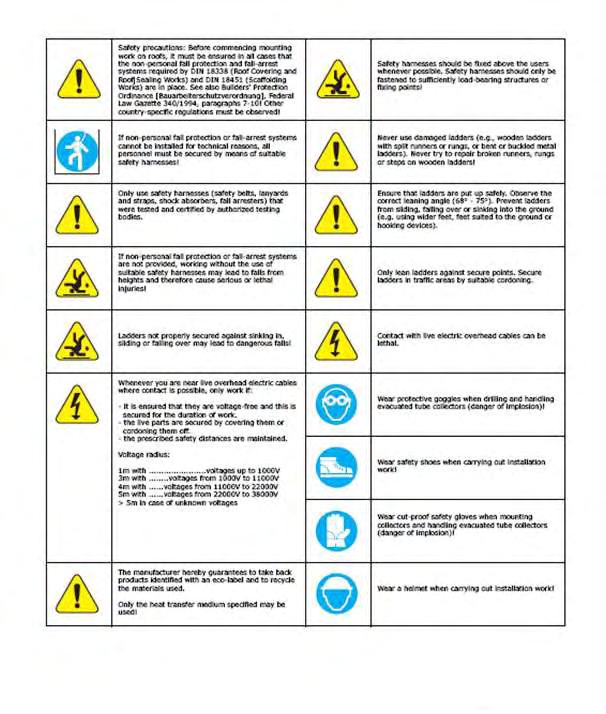
5 DOMESTIC SOLAR WATER HEATER SYSTEM INSTALLATION, OPERATION AND MAINTENANCE MANUAL The Free Hot Water domestic solar water heating system has gone through an extensive design, technical and performance review by the Solar Rating & Certification Corporation (SRCC). The installation of your Free Hot Water system is intended to be executed by properly licensed and experienced professional contractors in accordance with SRCC Standard OG-300, "Operating Guidelines and Minimum Standards For Certifying", and must conform to applicable federal, state and local regulations, codes, ordinances and standards governing the installation of solar water heating systems. The solar energy system described by this manual, when properly installed and maintained, meets the minimum standards established by the SRCC. This certification does not imply endorsement or warranty of this product by the SRCC. OG-300 system certification is granted to Free Hot Water by the SRCC. It may not be used for any commercial purpose without the prior written consent of Free Hot Water. Free Hot Water must approve any deviation from the materials and methods described in this manual in writing. CONGRATULATIONS! Congratulations on investing in one of the most advanced solar water heating systems available. Utilizing the free, environmentally friendly energy from the sun to heat water for your home makes so much sense. Solar energy is efficient, safe and reliable and your decision to use solar energy is helping to preserve our environment and to reduce our rapid depletion of non renewable, fossil fuels. The FREE HOT WATER solar water heating system uses the sun s energy as a source of heat to produce hot water for domestic household use. Designed to meet the certification requirements of SRCC 0G-300, FREE HOT WATER solar water heating systems are reliable, and can typically generate from 50% to 80% of your annual household water heating needs from the sun. Your remaining hot water needs can be supplied by your existing electric or gas water heater or boiler. Results will vary based upon on your specific region in the country. Your new Free Hot Water System uses state-of-the-art technology and will provide you with many years of maintenance free and dependable service. If you have any questions, please feel free to contact your local dealer or our home office. Introduction The system performance varies as a function of the household hot water load. The ambient air temperature, the roof pitch and orientation along with seasonal solar intensity will determine the amount of hot water generated by your FREE HOT WATER solar water heating system. Your FREE HOT WATER solar water heating system uses a circulation pump that circulates a propylene glycol heat transfer fluid throughout the system. This fluid protects the collector piping from freezing, prevents corrosion of system components, and keeps scale deposits from forming that could reduce the performance of the system. Proper maintenance of the propylene glycol in the system can protect the solar water heating system to minus 40 Fahrenheit. This manual is intended to familiarize you with the proper installation and maintenance of your FREE HOT WATER solar water heating system. This system must be installed by a licensed solar or plumbing contractor in accordance with SRCC Standard OG-300 and all applicable national, state and local codes. Failure to follow the procedures described in this manual can void the manufacturers warranty.
6 System Description The FREE HOT WATER solar water heating system is a closed-loop active solar system which, when installed with a suitable auxiliary heat source, can act as the primary source of domestic hot water for residential use. The system components provided with the FREE HOT WATER solar water heating system include the solar collectors, collector flashings, solar loop pipe and fittings, solar storage tank, solar pump station and controller, temperature sensors, expansion tank, air separator, mixing valve, and non-toxic propylene glycol heat transfer fluid. The solar collector is the engine of the FREE HOT WATER solar water heating system. When the sun is shining, the heat energy is absorbed by the solar collector and transferred to the heat transfer fluid circulating through the solar collectors. The system pump efficiently circulates this heated fluid through the collector s piping and the heat exchanger located in the solar storage tank. As the heat transfer fluid passes through the heat exchanger, the heat in the fluid is transferred by conduction to the potable water in your solar storage tank causing the temperature in the tank to rise. This process continues as long as the sun is shining or until the temperature in the solar storage tanks reaches its maximum temperature set point. General Instructions Installation must only be carried out by qualified personnel. The entire information in these instructions is intended exclusively for such qualified personnel. Only the supplied material should be used for the installation. Prior to starting installation and operation of the solar collector system, please inform yourself about the applicable local standards and regulations. The use of a carrying strap is recommended for transporting the collector. The collector must not be lifted at the connections or on the threading. Avoid impacts and mechanical influences on the collector, in particular on the solar glass, the rear panel and pipe connections. The collectors may only be mounted on sufficiently load-bearing roof surfaces and substructures. It is imperative that the static load bearing capacity of the roof or substructure is checked in terms of local and regional conditions prior to installation of the collectors by the customer, if necessary through the involvement of a structural engineer. Particular attention should be paid to the quality of the (timber) substructure in terms of the stability of the screw connections necessary for fastening the collectors. Specifications The FREE HOT WATER solar water heating system is designed to produce domestic hot water from either solar collector, an electrical or gas backup, or a boiler back up (provided by others). The FREE HOT WATER systems can also be used as a solar preheat system to conventional electric or gas water heaters (provided by others). Collectors and flashings FREE HOT WATER solar collectors and flashings allow for a low profile, roof integrated, solar panel installation. The FREE HOT WATER collector is made up of copper tubes and a plate that is covered with a highly selective absorber coating; this assembly is enclosed in a well insulated aluminum frame or box and covered with low-iron tempered glass glazing. FREE HOT WATER solar water heating systems are available for integration onto either shingle or tile roofs. The collector is suitable for angles between 15 (minimum) and 75 (maximum). The collector connections and the ventilation openings must be protected against the penetration of water as well as against contamination through dust etc.
7 Solar Storage Tank All FREE HOT WATER solar water heating systems will include a solar storage tank with the solar heat exchanger located in the bottom section of the tank to heat the entire water volume of the tank. The tank contains a thermometer located on the outside of the tank so you will know the temperature in the tank. Collector Loop Piping FREE HOT WATER solar water heating systems are designed for use with copper pipe or pre-insulated corrugated stainless steel flexible piping. No other piping may be substituted for use in the solar loop. Collector piping installation requires the use of copper and brass fittings in the collector loop. Piping in new solar installations may have dirt, grease, or other impurities that over time affect the quality of the propylene glycol heat transfer fluid. A thorough cleaning is required before charging the system with glycol. All vertical piping between the storage tank and the collector shall be supported at each story or at maximum intervals of ten feet (10 ) using pipe hangers. If additional supports are needed, copper plumbers tape or tube strap may be used. The pipe insulation may not be compressed or crimped by the strapping material. The installation of all horizontal and vertical piping may not reduce the performance or rating of any structural member or fire rated assembly. Adhere to all applicable local codes and ordinances. The collector loop cold supply and hot return lines must be well insulated with the high quality flexible closed cell insulation to minimize heat loss. There shall be no exposed piping or fittings. The wall thickness of the pipe insulation should not be less than ¾. Any above ground exterior pipe insulation that may be subject to UV degradation must be wrapped with foil tape or painted with two coats of high quality water-based acrylic resin coating. Pump Station Controller All FREE HOT WATER solar water heating systems include a pump station controller that include the temperature and pressure gauges, pressure relief valve, check valves, ball valves, fill and drain valves, and differential controller required to properly operate the FREE HOT WATER solar water heating system. The system temperatures for the collector and storage tank can be read from the differential controller. Typical tank operating temperatures can range from the cold supply of F up to 180 F which represents the high limit of the tank. This will vary depending on the climate where the system is installed. The collector temperature sensor should be 5-20 F above the tank sensor during normal operation. During idle periods, when there is no sun, the collector will read the ambient temperature and when there is full sun upward to 250 F. Balance of Systems The balance of components in all FREE HOT WATER solar water heating systems: solar loop pipe and fittings, temperature sensors, expansion tank, air separator, mixing valve, and non-toxic propylene glycol heat transfer fluid components carry temperature and pressure ratings required of the FREE HOT WATER solar water heating system design. Freeze Protection The FREE HOT WATER solar water heating system can be operated down to ambient temperatures of 40 F using proper concentrations of propylene glycol. Freeze tolerance limits are based upon an assumed set of environmental conditions. Refer to the propylene glycol specification sheet under the Flushing and filling section of this manual for recommended concentration of propylene glycol and distilled water to provide adequate freeze protection in your specific climate. The differential controller uses temperature sensors to monitor the temperature difference between the collector and the solar storage tank. The controller turns on when the collector is 20 F above tank

8 temperature and turns off when the differential drops below 10 F. HOUGHTON CHEMICAL CORPORATION SAFE-T- THERM, ECONO-THERM and Safe-T-Therm propylene glycol heat transfer fluid shall be used in this system as the primary freeze protection agent. Unauthorized fluid substitutions can result in a threat to health, welfare and safety and may cause the system piping to freeze. All component warranties express or implied, are voided if uninhibited glycol, potable or distilled water are substituted for the specified heat transfer fluid described in this manual, or if the heat transfer fluid is not maintained in accordance with the manufacturer s instructions. Freeze tolerance limits are based upon an assumed set of environmental conditions. Extended periods of cold weather, including ambient air temperatures above the specified limit may cause freezing in exposed parts of the system. It is the owner s responsibility to protect the system in accordance with Free Hot Water s instructions if the ambient air temperature approaches the specified freeze tolerance limit. Legal Guarantee Legal guarantee claims can only be made if the supplier's own antifreeze has been used and maintenance has been carried out correctly. Installation by qualified personnel with absolute adherence to the instructions is a prerequisite for the justification of claims. Tools Needed
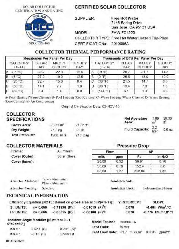
9 Collector Specifications High Performance Thermal Collector Optimal Value for the Money Aluminum Frame PVD Selective Coating Thermal Insulation - Polyurethane Foam Tempered Solar Safety Glass Suitable for Closed & Open Loop Systems Pitched and Flat Roof Installation Dimensions X 41 X 3 Thermal Output 1.26 Kw per hour Max Stagnation (f) 453 Max PSI-145 Absorber Capacity.60 gal. Manifold 3/4 - Risers 3/8 Free Hot Water item #: FHWC-FC Gross Area: m2, sf Net Aperture: 1.89 m2, sf Weight - 60 Lbs 10 Year Limited Warranty Approvals - SRCC OG 100 SRCC Daily BTU's - 21,500
10

11 Pressure drop and flow rates Mass flow rate To ensure the performance of the collector, a specific flow rate of.5 gallons per minute is to be selected up to a collector panel size of approximately 27 sq. ft. Pipe diameters Dimensions table with a specific flow rate of.5 gallons per minute Collectors Up to 6 Up to 13 Up to 22 Up to 45 Pipe Diameter (inch) ½ ¾ 1 1-¼ Pressure loss collector for anti-freeze / water mixture (40% / 60%) at a thermal conducting temperature of 122 F. Pressure loss curve: p = 0, x² + 0, x Flow Rate (kg/h) Pressure Loss (mbar) Pressure loss collector for anti-freeze / water mixture (40% / 60%), Temperature of 122 F
12
13
14 Precautions For safety reasons you should only fill the collectors when there is no direct irradiation from the sun (covering the collectors can be an option). Especially in regions exposed to frost, for flat plate collectors you should use a mixture of anti freeze with water (40% anti freeze). The solar thermal system should be filled and commissioned within one week of installation, because heat build-up in the collector array can damage the flat gaskets in empty systems. If this is not possible, the flat gaskets should be replaced before commissioning to prevent leakage. Attention : Anti freeze that is not premixed must be mixed with water prior to charging the system Recommended antifreeze for flat plate collectors FHWM-GY % antifreeze / 75% water mix - freeze point 14 F 40% antifreeze / 60% water mix - freeze point -5 F 50% antifreeze / 50% water mix - freeze point -25 F It may not be possible to completely empty collectors one they have been filled. For this reason collectors exposed to frost should only be filled with a distilled water/antifreeze mixture, also for pressure and function tests. Alternatively, the pressure test can also be carried out using compressed air and leak detection spray. Installing the temperature sensor The temperature sensor should be installed in the sensor sleeve nearest to the collector array flow. To ensure optimal contact between the sensor and the surrounding environment, the gap between the sensor sleeve and the sensor element should be filled with a suitable conducting compound. All materials used for installing temperature sensors (sensor element, conducting compound, cables, sealing and insulating materials) must be suitably temperature resistant (up to 482 F). Operating pressure: The maximum operating pressure is 145 psi. Bleeding The system must be bled: - When commissioning the system (after filling the collectors) - 4 weeks after commissioning - When necessary, e.g. if there are malfunctions
15 Warning: Risk of scalding due to steam and hot heat transfer fluid! Only operate the bleeding valve if the temperature of the heat transfer fluid is < 140 F. When bleeding the system, the collectors must not be hot! Cover the collectors and, if possible, bleed the system in the morning. See Material Safety Data Sheet on page 49 for safety information. Check heat transfer fluid The heat transfer fluid must be checked every two years with regard to its antifreeze and ph value. - Check antifreeze using antifreeze tester and replace or refill if necessary! Target value is ca F and - 22 F depending on climatic conditions. - Check ph value with a ph indicator rod (target value approx. ph 7.5): If the limit ph value is less than ph 7, replace the heat transfer fluid. Maintenance of the collector The collector or the collector array must be inspected visually, once a year, for any damage, leaks and contamination. Additional recommendations on operation and maintenance can be found in the supplier's general documentation and instructions on commissioning and maintenance. Connecting the collectors to one another The collectors must be connected to one another and/or to the connection pipes using the supplied connectors. When tightening the union nuts and/or compression fittings, always balance (counter) the torque* with a pipe wrench or another spanner to prevent damage to the absorber. Do not run the solar collector(s) without a Pressure Relief Valve, safety valve in the system to avoid over pressure in the solar circuit. Warning: Freeze tolerance limits are based upon an assumed set of environmental conditions. Warning: If the freezing point of the fluid in an exposed part of the system is above the freeze tolerance limit specified for the system: Extended period of cold weather, including ambient air temperatures above the specified limit, may cause freezing in exposed parts of the system. It is the owner s responsibility to protect the system in accordance with the Supplier s instructions if the air temperature is anticipated to approach the specified freeze tolerance limit.
16 Solar Collector Orientation Operating your Free Hot Water solar water heater for optimal efficiency is based on the correct orientation, pitch, and location of the solar collectors. In North America, collectors should be oriented due south, however may be oriented up to 45 degrees east or west of due south with minimal losses in solar gain. Optimal pitch is +/ 10 from the latitude of the installation site. Free Hot Water solar collectors must be installed at a minimum pitch of 15 degrees from horizontal, and for optimal performance, the recommended pitch is between degrees. The collector should be mounted as close to the storage tank as possible to minimize heat loss in the piping runs. The solar collector must be located in an area of the roof that will be un-shaded for the majority of the day (from 9:00 3:00) all year round. Adjacent buildings and trees should be checked for possible winter shading. The following diagram below is an example of how the collectors can be connected to one another. However, the actual connection may be different depending on structural conditions. A maximum of 6 collectors may be connected in a series! If a collector panel is made up of more than 6 collectors, the panel must be connected several times in parallel
. 2.")
. *Note: you need to install a screw into one of the holes in the mounting bracket, not both holes (fig 1.1).")
17 Installation Steps for Pitched Roof Mounting 1. Locate and mark the roof rafters into which the solar collector mounting brackets will be mounted (one way to find rafters is to see the tails at the edge of the roof). 2. To create a set point for plumbing and level installation, measure the distance from the edge of the roof to the desired mounting points and mark the points where the collector mounting brackets will be installed (fig 1.2). *Note: you need to install a screw into one of the holes in the mounting bracket, not both holes (fig 1.1). * Note: for collector model 7000 upper and lower mounting bracket should be 78 apart measured from top of top bracket to bottom of bottom bracket. * Note: both the bottom and the top mounting brackets should be placed as per figure 2.0 from each other as possible in the width dimension. Fig 1.1 Fig Determine where penetration will be to connect the solar hot water collector with the storage tank and/or the water supply (use 2 pre-insulated ¾ steel flex hoses or 2 insulated ¾ copper pipes for that connection). Note: *For a two-collector system that will be elevated above the roof surface, a good location for this penetration is directly between the two collectors. 4. Holes should be slightly overlapping to form a sideways 8 shape (see illustration 1.3). Mark the penetration before making holes. If you are installing on a composition shingle roof make holes 5 below the bottom of the shingle above the penetration.


18 Fig Using a hole saw, cut the hole (penetration) for the 2 hoses or pipes from step If using flex hose: before connecting the hose, measure, cut, and lay out the hose, including enough length for 8 of hose above the roof. Pull the hose through the hole. 7. Begin mounting bracket installation with bottom bracket. Mark a straight chalk line between the 2 bottom bracket mounting points. Fig For composition shingle roof, DO NOT PENETRATE THE COMPOSITION SHINGLE. Before installing screws, lift the composition shingle at the install point and slide the mounting bracket in, beneath the top composition shingle. Place the bracket so that the top surface composition shingle clears the bracket when folded (lifted) up or down and mark an outline of the mounting bracket where the mounting bracket will be fastened to the roof rafter or other appropriate mounting substrate. The marked area should be 1.5 wide and 2.5 high. 9. Next, using a cutting tool, cut out a piece of the roof material beneath the top layer of the composition shingle (the top layer will NOT be penetrated for the mounting brackets) as marked 1.5 X 2.5 in the shape of the mounting bracket. Cutting out a piece of roofing material will provide for a flush-mounted roofing bracket.
 using a 7/16 drill bit.")


19 Fig 1.5 Fig 1.6 Fig Pre drill mounting bracket screw holes into rafter or other appropriate mounting substrate (one hole per bracket) using a 7/16 drill bit. 11. FOR ONE BOTTOM BRACKET ONLY, apply Solarflex in bracket screw holes, on roof surface where bracket will be placed, and on bracket surface that will be facing down. Fasten first bottom bracket only to rafter or substrate using ½ screw. Note: *begin installing second bottom bracket only after confirming level installation. 12. Follow Steps 8-11 for the second bottom bracket BUT DO NOT YET FASTEN THE SECOND BRACKET WITH SCREW. 13. WITHOUT TIGHTENING IT COMPLETELY, place the bottom profile on the bottom brackets using the clamps and ½ bolts. 14. Using a 4 level, make sure the profile is level. 15. Once the profile is level, remove it and fasten the second bottom bracket to the roof using ½ screw. Fig Apply AT (recommended, not supplied-fhw-aa 60050)to ½ bolts for clamps. Fasten Clamps to brackets using ½ bolts and washers. Attach profile to clamps, tighten completely. 17. Follow steps 1-16 for top mounting brackets.


20 Fig Place collector on profiles, checking to make sure it fits and lines up appropriately. Recommend Anchor Points 19. Once collector fits and lines up appropriately, apply AT 60 to ½ bolts for collector and fasten collector to profiles using ½ bolts and washers.
 and with storage tank, using flex hose or copper pipe and compression fittings.")
21 20. If installing more than one collector, cut flex hose or copper pipe in length necessary to connect collectors. On all plumbing connections use Anti Leak (part # FHWM-AA-72050) 21. Connect collectors with each other (if installing more than one collector) and with storage tank, using flex hose or copper pipe and compression fittings. Note: * Tighten compression fittings gently by hand and then 1.25 turns with a wrench. Avoid overtightening as this can damage the flex hose or copper tubing. 22. Cap unused collector connections with cap. 23. If not already labeled, install hot and cold water in and out labels to collector and storage tank. 24. Test system, checking for any leaks and for performance. Collector mounting must be capable of maintaining tilt and azimuth. Fig 1.91
. 2.")
 will be installed (fig 2.1). Fig 2.2 Fig 2.3 Fig 2.1 1.")
22 Flat Roof Installation Instructions 1. Locate and mark the roof rafters into which the solar collector mounting Frame will be mounted (one way to find rafters is to see the tails at the edge of the roof). 2. To create a set point for plumbing and level installation, measure the distance from the edge of the roof to the desired mounting points and mark the points where the collector mounting frame (fig 2.2) will be installed (fig 2.1). Fig 2.2 Fig 2.3 Fig Follow the plumbing connections (Blue for Supply and Red for return) Determine where penetration will be to connect the solar hot water collector with the storage tank and/or the water supply (use 2 pre-insulated stainless steel flex hoses or 2 insulated copper pipes for that connection). 2. Once the frame(s) are attached to the roof, install the profiles as per fig Proceed installing the collectors using the M8 screws provided with the frame kit as per the illustrated in fig 2.4 Fig 2.4


23 4. If you have more than one bank of 3 collectors you will need to use the FHW expansion band as illustrated in fig 2.5 Fig At the end of every bank please connect to the main as described in fig 2.6 Fig 2.6

24 Installing the Solar Tank IMPORTANT INFORMATION Free Hot Water Solar Storage Tank should be installed in accordance with these installation instructions, Local plumbing regulations, municipal building codes and any other relevant statutory regulations. Observation of these instructions and the associated component instructions is most important and failure to do so could void the benefits of warranty. All work is to be carried out by a registered plumber, and to be in accordance with Local and National Occupational Safety Guidelines. The information contained in this manual, and all other information or advice provided by Free Hot Water Limited in connection with the purchase, installation use and service of the Free Hot SST, is given in good faith. Free Hot Water will not be liable for any person for any inaccuracy or omission in the information arising through the fault of Free Hot Water directly or indirectly. A pressure-limiting valve of 70 PSI (500kPa) max rating must be fitted. Failure to install a pressure limiting valve where required will void the warranty. SAFETY Scalding occurs at 120 F (500C). This appliance is capable of providing hot water above this temperature. All installers must install an anti scalding valve and advise customers of the potential hazard of scalding in accordance with the relevant National standards. Young children should not play with the appliance. A combination temperature Pressure Relief valve with a maximum rating of 120 Psi (850kPa) must be fitted. Water may drip from the discharge pipe of this valve. This pipe must be left open to the atmosphere. For more information, please refer to the Regular Care section of this manual. These safety devices must not be tempered with or removed from the appliance under any circumstances. All components must remain accessible for maintenance and servicing. Secure all pipe according to regulation and do not over tighten hangers as to compress insulation. About Your Water Heater 1. Free Hot Water SST is a high technology tank backed up by new manufacturing methods in order to offer quality of goods to consumers. 2. The main goal of producing the Free Hot Water SST Tanks is heating and storing potable hot water in a main pressure storage tank using solar energy. Potable hot water is stored in the main water storage tank separately from the heating liquids in the coils.
25 3. The heating fluid, which is heated in the heat source, is circulated between the heat source and tank s coil. The warmed fluid takes its heat from the heat source and transmits to the water heater. 4. Free Hot Water tank inner surface is enameled. The meaning of enameled coating is as covering sheet iron s inside surface with glass. 5. Free Hot Water tanks are protected by a magnesium anode rod in order to prevent the damage of cathode corrosion. The magnesium anode rod ought to be replaced every 36 months by a certified plumber, and can be installed and uninstalled. The replacement steps of the magnesium anode rod must be followed according this manual. 6. Free Hot Water exterior surface is covered by 2.5 lbs/cm³ (40 kg/m³) and 2 (50 mm) polyurethane (except 800D and 1000D) in order to diminish the loss of the heat. The Free Hot Water 800D and 1000D 1. insulation foam is removable. This convenience allows easy delivery and access through narrow doors for tank placement. 7. The type of water heater to choose (single or double coil) depends on the heater and if you are planning to extract heat. For example, if the tank will be heated with a solar system, Free Hot Water single coil water heater would be appropriate. 8. Free Hot Water SST have been produced to suit a wide range of applications and installation shapes. 2. In this manual we present the most common applications, however if you require advice on any other application, please contact our service desk on or info@freehotwater.com Plumbing Connection Delivering and mounting the Free Hot Water tank 1. The product should be kept away from sharp tools during loading or delivering. 2. The product s inlet and outlet pipes should be protected against any damages during delivery. 3. The product should not be left or placed where it s exposed directly to weather such as direct sunlight, rain snow etc. 4. If possible leave headroom of one water heater length so the anode can be inspected or replaced. Remember you may have to remove the entire water heater later for servicing as per instructions in this manual. 5. Outdoor installations decrease the water heater performance and may increase the energy consumption. 6. If the product is installed on the floor, the floor must be dry and moisture proof. 7. Consider a drainage tray when required. 8. Tank must be strapped and mounted in accordance to local plumbing regulations and seismic regulations. 9. Free Hot Water Limited does not accept any responsibility, if the product is physically damaged or operates inefficiently due to wrong mounting or inappropriate delivery. Basic Plumbing connection of the Water heater 1. In order to use the water heaters to their highest efficiency, tanks must be connected according to the diagrams. 2. The capacity of the water resource has to be chosen and adjusted in order to maintain the hot water supply demand. 3. Start with the Basic Diagram before conducting any specific application connection. 4. Fit the cold inlet valves prior to commissioning the tank. 5. Ensure that the TPR Valve is fitted and that the service circulation is blocked or connected prior to commissioning the tank with water. 6. Lag all hot water pipes coming out of the water heater.

26 Plumbing Connection of additional applications 1. Please follow the diagrams and the notes. 2. If you are in doubt or attempting to install an application outside the below diagrams, please contact Free Hot Water service desk for advice. IMPORTANT NOTE: When using copper pipes, use Teflon or FHWM neutral adaptor between the brass fitting and the port thread to prevent electrolysis Tank Sizes 79 Gallon - FHW Single Coil Solar Tank 79 gal - FHWC-STEN-079-SC 105 Gallon - FHW Single Coil Solar Tank 105 gal - FHWC-STEN-105-SC Important Notes: Not all valves are supplied with the water heater. The above diagram describes valves for a mains pressure arrangement; however the tank could also be fitted to a low pressure system. Free Hot Water tanks are equipped with a service circulation port. Free Hot Water recommends ¾ Stainless Steel Helical Flexible Tube for connections on the roof (no welding work needed and pre-uv R6 insulated), or use standard ¾ copper pipe. All outdoor pipe is to have UV protected insulation. Final 5 feet of cold water piping is insulated to R-2.6
27 Important Notes: 1. The diagram shows generic drawings of connections to and from Free Hot Water tank. Follow the specific instructions of the solar panel supplier for the actual detailed arrangement, components and valves. 2. When using Free Hot Water tanks, solar collectors should be installed in bottom coil (boiler, wetback or heaters should be installed in upper coil. 3. It is highly recommended running the solar system via the Free Hot Water coil on a close loop arrangement. Open loop solar is also possible using the Service Circulation port for the solar return instead of the Coil Hot port, and branching of the Cold Inlet instead of using the Coil Cold port. 4. When connecting commercial solar system, ensure that the energy going through the solar coil is lower than the max kw rating of the coil as per instructions. Excess energy above the coils rating will void the warranty. Warning: Open loop solar carries a frost risk to the panels since antifreeze is not used. This OG300 system may not qualify for Federal and State rebates if Open Loop method is used. Commissioning the Solar Tank VERY IMPORTANT: Prior to turning on any heating application such as solar, boiler or a heater, the tank MUST BE FILLED UP WITH WATER 1. Make sure that all hot water taps are close off 2. Open the inlet tap fully to fill up tank 3. Open each hot water tap till water flows freely 4. Check all pipes for leaks 5. Switch on the elements and set the timer/controller (if one is installed) 6. Attend to any other external heating applications Draining The Water Heater 1. Turn off the power supply of the elements 2. Turn off all external heating applications 3. Turn off cold inlet supply at the 3 in 1 valve or at the meter 4. Open a hot water tap to drain the plumbing 5. Turn off the hot water tap 6. Disconnect the hot water outlet union 7. Open to atmosphere Cold Water Expansion Valve to let water flow via the 8. drain pipe Water Quality Free Hot Water SST heater has been manufactured to deal with most qualities of US water supply. Desired water quality levels: ph Level between 6.5 and 8.5 Chlorides: up to 200 ppm, Total Dissolved Solids (TDS) up to 1000 mg/l Saturation Index between -0.8 and +0.8 If your water quality or the heating liquids are outside the above range, you should fit appropriate water filtration.

28 Caution: If water TDS is above 600 mg/l, there is a possibility of hydrogen gas accumulating in the top of the water heater during long periods of no use. If the water heater has not been used for more than 2 weeks: 1. Open the hot water tap and let water flow for 1 minute. 2. Hydrogen gas is flammable; therefore make sure that there is no smoking, sparks or naked flames near the tap. 3. Do not operate any hot water appliance such as a washing machine or a dishwasher prior to the above procedure. Regular Care Every Six Months: Near the top of the water heater you will find the TPR Valve (Temperature Pressure Relief Valve). Raise the lower lever and gently release some water into the relief pipe. Notes: 1. If water does not flow down the relief pipe, or if water does not stop flowing once you released the lever, contact your plumber. 2. It is normal for the valve to release small amount of water during heating cycles. 3. Never block the relief drain pipe. Every 3 years - maintenance: A qualified plumber should check and if needed replace the sacrificial anode of the water heater. Every 5 years - maintenance: A qualified plumber should replace the TPR valve, of the water heater and should clean coils of the tank via the clearing door. Regular Care Service Person Anode Replacement Free Hot Water SST 1. Disconnect the power supply to the water heater 1. Drain approximately 5 to 10 lt. from tank as per instructions. 2. Unscrew service cap (11) gently 3. Take out the soft foam insulation (10) and disassemble anode ground cable from flanges cap (7) and then from flanges (2). 4. Disassemble the flanges (7) and then remove the flanges gasket (4). 7. Open the nut that is on the flanges (7) and attach it to the anode rod. 8. Remove old anode rod (3) over flanges and keep the anode insulation bush and anode gasket (5).


29 9. Assemble new anode rod from the side of enameled flanges (7); leave insulated bush (5) on the other side, and install nut over anode behind the beam gear side. 10. Locate flange gasket through inlet of the tank. Replace gasket if needed 11. Locate flange exactly central side of the tank flange. Fasten nuts in a cross tightening order as per page 18. Don t leave out nut flakes (6) it needs to be directly opposite flange number (1) as shown. 12. Assemble stone wool, place the tail of thermometer couple on the bush, which is on the flange. Locate the service cap on the bush of top cap. Sensor Connections Sensors sense the temperatures when the tank is connected to heating applications, and transfer the reading to the controllers, such as 3 way valve, pumps and other electronic controllers. Sensor bushes are located in the most appropriate level for heat distribution in the tank. Sensor holders must be used and supplied by the electronic control unit supplier. The holders attach the sensor to the surface which prevents the sensors from falling down from the hive. Make sure that probes are pushed all the way into the sensor tubes. Anode Replacement 1. Disconnect the power supply to the water heater. 2. Drain approximately 2 to 4 gallon from tank as per page 13 instructions D & 1000D: Drain entire water from tank as per page Remove tank top cap (1) 5. Take out stone wool insulation carefully and disassemble anode ground cable from flanges cap (6) then from flanges (10). 6. Disassemble the flanges (6) and (3) by removing the nuts. 7. Remove the flanges gasket (8). 8. Disassemble the flanges nut (4) and attached the anode rod (9). 9. Remove old anode rod (9) over flanges and keep the anode isolation bush and anode gasket (8). 10. Assemble new anode rod from the side of enameled flanges (7) and leave isolated bush (5) on the other side, and install nut over anode behind the beam gear side.
30 11. Locate flange gasket through inlet of the tank. Replace gasket if needed 12. Locate flange exactly central side of the tank flange. Fasten nuts in a cross tightening order. Don t leave out nut flakes (5) it needs to be opposite flange number (1) as shown. 13. Close the service cap on the bush of top cap. Warranty Exclusions: Free Hot Water warranty will not cover the following situations: 1. Failure because of misuse, damage, neglect or abuse 2. Product is not installed, operated or serviced in accordance with this manual or the NZ building code 3. Damage caused by an act of God 4. Water quality outside the range of this manual 5. Connection of any associated heater with a max kw Rating higher than the coil capacity as per page 4 of this manual 6. Use of water temperature or pressure, or coil temperature or pressure, outside the restrictions of page 4 of this manual 7. Water hammer or negative pressure occurring in water Plumbing Notes: Free Hot Water is not liable for any sequential damages such as walls, carpets, furniture etc. Replacement water heater or parts provided under this warranty does not carry a new warranty. The unexpired warranty remains effective. Free Hot Water is only liable for the water heater and will not assume directly or indirectly any other obligations in connection with the product. REGULAR CARE Installation Date: / / 6 months: TPR Valve check Date: / / 12 months TPR Valve check Date: / / 18 months TPR Valve check Date: / / 2 years TPR Valve check Date: / / 30 months TPR Valve Date: / / 3 years service by: Date: / / 42 months TPR Valve check Date: / / 4 years TPR Valve check Date: / / 54 months TPR Valve Date: / / 5 years service by: Date: / / WARRANTY REGISTRATION Warranty registration is highly important, as it confirms installation date and installations type to ensure that you enjoy the full benefits of the product warranty. Registration Option 1: go to under warranty register Registration Option 2: Call our service desk on Registration Option 3: Fax the below form to

31 Registration Option 4: Send the below form to Free Hot Water, 2146 Bering Drive, San Jose, CA WARRANTY Free Hot Water will repair or if necessary replace a defected water heater or parts failed due to faulty manufacturing as per the following schedule: Durability
32 Free Hot Water SST meets the requirements of the US Building Code for durability given that: 1. Installed and maintain by a qualified person and according to the building code and this manual 2. No damage in any way 3. Water quality according to this manual Change of Ownership This warranty extends beyond the original purchaser of the water heater. Standard Installation Standard installation includes all connections as per this manual and any other connections approved by Free Hot Water service desk. The water heater is installed where delivery and access is standard. The customer may have to pay additional cost due to: difficult access (incl. roof cavity & narrow space), multiple storey or freight outside main centers. PRODUCT INFORMATION General product information Maximum working pressure 115 PSI (800kPa) Maximum water temperature 190 F (90 C) Maximum coils working pressure 115 PSI (800kPa) Maximum heat exchange temperature 200F (95 C) Enameled steel automatically welded Insulation 2 (50 mm) polyurethane Usage indoor only Note : The product must not be exposed direct sunlight, rain, snow, etc. Outdoor installation decrease heater performance & may increased energy consumption. Label indicating maximum pressure and temperature must remain on tank. Do not impair walkways or enclose areas that cannot be serviced. Make sure to seal all openings created to not allow vermin intrusion. Adhere to all applicable codes and the National Roofing Contractors Association. Structural members penetrated by solar system components must meet code. Building materials adjacent to solar components are not to be exposed to elevated temperatures. Penetrations through fire-rated assemblies cannot reduce fire resistance below code. Components exposed to public traffic are maintained below 140 F or insulated/isolated. Adequate Capacity Manufacturers recommendation: Minimum Storage Tank Capacity Calculation (Size of collector sq. ft. x 1.25 x number of collectors) 2 Collectors sq. ft. x 1.25 x 2 = 70 minimum number of gallons storage 3 Collectors sq. ft. x 1.25 x 3 = 104 minimum number of gallons storage Tank Certification information on following page:
33
34 Pump Station and Controller Solar controller: The solar controller, turns on or off solar loop circulator depending on the heat gained in the solar collectors. The controller will also limit over heating in the solar collectors and overheating in the solar storage tank. Locate the collector hot supply - the hot supply pipe must be cut to length using a tubing cutter and connected to the pump station. Locate the collector cold supply - the cold supply pipe must be cut to length and connected to the connection of the pump station (blue). Connect pipes between pump station and solar storage tank. Pump Station 1 way (A) all valve on the return way (thermometer with blue ring and scale 0-250F with "Sola/' check ball. Solar Check bell - It is included into the ball valve. It ensures the seal and low head losses. To exclude the check ball valve, for instance in case of emptying rotate the handle by 45' clockwise. (B) Pressure Relief Valve - The security unit, approved according to97/23/ce and 01.SOLAR TUV, protects the installation from the overpressures. It is calibrated at 6 bar. over this Pressure the security unit starts. It is also provided with a manometer and with a connection to the expansion vessel by a %" flexible kit. (C) Flow meter - The flow meter allows to regulate the flow rate to the capacity of the installation, by a 3-way ball valve. lf the valve is closed the usual circulation is cut off, it is possible to use the side filling tap to fill the installation. There is also another side tap for the draining. The proximity 0f the two taps helps these operations minimizing the distance between the filling and the draining. The flow rate is measured and shown by the special sliding cursor: the measurement is immediate thanks to the proximity to the regulation valve. (D) Circulating pump - Three speed circulation pump with manual regulation. Thanks to the seal of the ball valves before and after the circulating pump, it can be removed without emptying the installation.
. Side opening for the security unit.")


35 Mounting the insulation box Measurements 150x425x150. Box with a special bracket to fasten the unit and with the groove for the cable. Cover with the opening for the cable press. (The cable press must be positioned towards the down, see the picture). Side opening for the security unit. A special window allows to read and to regulate the flow without removing the cover. Filling the installation: 1. Remove the plugs from the side valves and connect the hose unions. Close the ball valve and open the side filling valve and draining valve. 2. Starting the installation working: Open the ball valve and close the side filling and draining valves. Remove the hose unions and screw again the plugs. To avoid any casual opening of the side valves, it is better to stop the levers in the close position, as shown here. 3. Regulate the flow rate using the regulation rod until the right flow rate is shown. See page 45 for additional details.


36 Pump Station Options 2 way A. Ball valve on the supply way (thermometer with red ring and Scale 0-250F) with "Sola/' check ball. B. (Ball valve on the return way (thermometer with blue ring and scale 0-250F) with "Solar" check ball. C. Pressure Relief Valve - The security unit, CE and TUV approved, protects the installation from the overpressures. It is calibrated at 6 bar, over this pressure the security unit starts, It is also provided with a manometer and with a connection to the expansion vessel by a 3/4" flexible kit (optional), see here at the right. D. Flow meter - The flow meter allows to regulate the flow rate to the capacity of the installation, by a 3-way ball valve. lf the valve is closed the usual circulation is cut off, it is possible to use the side filling tap to fill the installation. There is also another side tap, for the draining. The proximity of the two taps helps these operations minimizing the distance between the filling and the draining. The flow rate is measured and shown by the special sliding cursor: the measurement is immediate thanks to the proximity to the regulation valve. E. Circulating pump - Three speed circulating pump with manual regulation. Thanks to the seal of the ball valves before and after the circulating pump, it can be removed without emptying the installation.

 A.")

37 Model with the vent air The vent air is a device that divides continually the air that can be in circulation together with the fluid. The air goes to the upper part of the vent air and it can be eliminated through the special drain while the installation is working. Unscrew of 360" the knurled metal ring lock. This operation has to be done at intervals. DANGER OF BURNS - To avoid any leakage of the fluid. Taking into consideration the very high working temperature, we recommend to fasten a pipe to the end of the drain. Connecting the Expansion Tank (2.1 Gallon) A. Flexible pipe coupling hose (not included) shall be approved by ASTM D750, ASTM D471 and STM D1149. B. Fiber sealing joint included. C. Connector with double check valve to disconnect the expansion vessel in a reliable and fast way without any leakage. D. Expansion vessel (2.1 gallon) with 314" threaded connection (available on request). E. Fixing bracket provided with plugs and screws to fix it to the wall. Fix the bracket (E) to the wall with the plugs (centre distance 55 mm). Screw the expansion vessel (0) lo the connector (C) and put it on the fixing bracket using the special groove then lock with the nut. Put the sealing joint (B) and screw the flexible pipe of the security unit (A) to the connector. F. REPLACEMENT OF THE EXPANSION VESSEL - The connector (C) holds up the expansion vessel and allows a quick detachment of it avoiding any leakage. By unscrewing the nut (F) it is possible to disconnect one end of the connector that remains screwed to the expansion vessel. The other end of the connector stays fixed on the bracket connected to the security unit. Both the ends have a check valve that becomes operative at the lime of the disconnection: this prevents any leakage both from be expansion vessel and from the flexible pipe. To put in function again the installation it is sufficient to connect the two ends of the connector and to fix them by screwing the nut (F). In That way the two check valves are disconnected and the expansion vessel is again connected to the installation. Caution: Tank must be supported in horizontal position to prevent damage to the tank.
38 Installing the Expansion Tank Follow all instructions and local codes during the installing of this product. Tanks are pre-charged to 12psi (83 kpa) and should be charged to the system pressure prior to installation in the system. Caution: Do not exceed the maximum pressure rating of the tank. After installing the ETX/ETSX 2.1 Expansion Tank Fill system. Vent air from system. Fire the burner to bring system to design temperature. After initial venting of air, additional air will vent as water is heated. Check system pressure after water is heated. If pressure is too high, drain water from boiler and adjust feed water pressure regulator (typically 12psi) (83 kpa). Service Hints 1. If the system pressure is too high: a. Check gauge calibration. b. Check to see if the ETX/ETSX tank has lost its air charge. Note: To get an accurate reading when checking ETX/ETSX tank air pressure with any tire gauge, disconnect the tank from the system. c. Check for faulty fill valve operation. First close manual shutoff located before the fill-valve, then draw system pressure down to 12psi (83 kpa) (or other preset pressure) and observe system for pressure buildup several hours later. d. Check for service water entering system from any other source such as a defective tank less heater. Use same procedure as above after shutting off possible water source. 2. If pressure relief valve drips water: a. First, check system pressure. If too high, follow steps 1.a, b, c, and d above. b. If pressure relief valve continues to drip water, even at reduced pressure, flush relief valve by quickly raising lever several times. If drip continues, replace relief valve. (see caution below) c. If multiple ETX/ETSX tanks are installed in the system, check pressure of each for possible air leaks. Be sure air valve caps are on tight. Caution: Relief valve will discharge hot water, therefore precautions must be taken to avoid scalding injury or water damage. A proper drain line connected to the valve outlet and run to a safe place of disposal must be installed. Expansion Tank Quick Sizing Chart - Watts ETX gallon Watts Expansion Tank recommendations (Net BTU/Hour 20,000 to 30,000 Tank ETX gallons) 2 collector 7000 series BTU/H 11,360 BTU s 3 collector 7000 series BTU/H 17,040 BTU s


39 Solar Thermal Controller Combining practical design with a feature rich, crystal clear operator guidance system, and sophisticated control in an extremely user-friendly package. Users are presented with programming and operational information, in graphical or plain written text formats. The STDC is designed to offer OEMS, installers and system designers an extremely compact, low cost, entry level platform capable of managing any one of 8 pre-programmed solar thermal system types in a single product. Intended for basic systems comprised of one collector array, and one storage tank or swimming pool. Can also used for boiler return loop heating, solid fuel boiler storage control, and storage tank heat transfer applications. The TDC3 differential temperature controller offers installers and system designers a price competitive platform capable of managing any one of 15 pre-programmed solar thermal system types in a single product. Based on program selection, South Facing as well as East + West facing collector configurations are possible. Single and dual storage tanks, swimming pools, boiler return loop heating and heat dissipation are also possible. Quiet and efficient variable speed pump control of wet rotor type circulators (up to 140watt) is also possible using the TDC3 s internal triac based speed control circuitry. In addition, every TDC series controller is capable of logging operational, and averaged solar performance data for up to 5 years**.

40 Solar Controller Installation Install the controller only in dry areas and under the ambient conditions. Carry out the following steps Unscrew cover screw completely 2. Carefully pull upper part of housing from lower part. 3. Set upper part of housing aside, being sure not to touch the electronics when doing so. 4. Hold the lower part of the housing up to the selected position and mark the 3 mounting holes. Make sure that the wall surface is as even as possible so that the housing does not become distorted when it is screwed on. 5. Using a drill and size 6 bit, drill 3 holes at the points marked on the wall and push in the plugs. 6. Insert the upper screw and screw it in slightly. 7. Fit the upper part of the housing and insert the other two screws. 8. Align the housing and tighten the three screws. Before working on the unit, switch off the power supply and secure it against being switched on again! Check for the absence of power! Electrical connections may only be made by a specialist and in compliance with the applicable regulations. Do not use the controller if the housing shows visible damage.
 and make electrical connections on the controller (s. D.1 D.")
, with its extensive text and graphics mode, is almost self-explanatory, allowing easy operation of the controller. The LED (2) lights up green when a relay is switched on.")
41 Controller Installation 1. Select necessary program/hydraulics 2. Open controller as described above. 3. Strip cables by 55mmmax., insert, fit the strain relief devices, strip the last 8-9mm of the wires. 4. Open the terminals using a suitable screwdriver (see right) and make electrical connections on the controller (s. D.1 D.20) 5. Refit upper part of housing and fasten with screw. 6. Switch on mains voltage and place controller in operation. Operation The display (1), with its extensive text and graphics mode, is almost self-explanatory, allowing easy operation of the controller. The LED (2) lights up green when a relay is switched on. The LED (2) lights up red when operating mode Off is set. The LED (2) fl ashes slowly red in the operating mode Manual. The LED (2) fl ashes quickly red when an error is present. Entries are made using four keys (3+4), which are assigned to different functions depending on the situation. The esc key (3) is used to cancel an entry or to exit a menu. If applicable there will be a request for confirmation as to whether the changes which have been made should be saved. The function of each of the other three keys (4) is shown in the display line directly above the keys; the right-hand key is generally has a confirmation and selection function.
42 Examples of key controller functions: +/- = enlarge/shrink values / = scroll menu down/up yes/no = approve/reject Info = additional information Back = to previous screen ok = confirm selection Confirm = confirm setting Setup Wizard The first time the controller is turned on and after the language and time are set, a query appears as to whether you want to parametrise (establish parameters) the controller using the commissioning help or not. The commissioning help can also be terminated or called up again at any time in the special functions menu. The commissioning help guides you through the necessary basic settings in the correct order, and provides brief descriptions of each parameter in the display. Pressing the esc key takes you back to the previous value so you can look at the selected setting again or adjust it if desired. Pressing the esc more than once takes you back step by step to the selection mode, thus cancelling the commissioning help. Finally, menu 4.2 under operating mode Manual should be used to test the switch outputs with the consumers connected, and to check the sensor values for plausibility. Then switch on automatic mode. Menu sequence and menu structure The graphics or overview mode appears when no key has been press for 2 minutes, or when the main menu is exited by pressing esc. Pressing a key in graphics or overview mode takes you directly to the main menu. The following menu items are then available for selection there: 1. Measurement - Current temperature values with explanations The menu 1. Measurement values serves to display the currently measured temperatures. The menu is closed by pressing esc or selecting Exit measurement values. Selecting Info leads to a brief help text explaining the measurement values. Selecting Overview or esc exits the Info mode. If Error appears on the display instead of the measurement there may be a defective or incorrect temperature sensor. a. 2. Statistics - Function control of the system with operating hours, etc The menu 2. Statistics is used for function control and long-term monitoring of the system. The menu is closed by pressing esc or selecting Exit statistics. Please note that the clock does not continue to run if the mains voltage is interrupted, and must therefore be reset. 3. Display Mode - Select graphics mode or overview mode Menu 3. Display mode is used to define the controller s display for normal operation. This display appears whenever two minutes go by without any key being pressed. The main menu appears again when a key is pressed. The menu is closed by pressing esc or selecting Exit display mode. 4. Operation Mode - Automatic mode, manual mode or switch unit off In menu 4. Operating modes the controller can either be placed in automatic mode, switched off, or placed in a manual operating mode. The menu is closed by pressing esc or selecting Exit operating modes.
43 When operating mode Manual is activated, the current temperatures and the selected parameters are no longer considered. There is a danger of scalding or serious damage to the system. The operating mode Manual may only be used by specialists for brief function tests or during commissioning! 5. Settings - Set parameters needed for normal operation The necessary basic settings required for the control function are made in menu 5. Settings. This does not under any circumstances replace the safety facilities to be provided by the customer! Temperature values which are set too high can lead to scalding or damage to the system. Scalding protection must be provided by the customer! If the set temperature difference is too small, this may result in ineffective operation, depending on the system and sensor positions. Special switching conditions apply for speed control. 6. Protections - Solar and frost protection, re-cooling, anti-seizing protection System protection prevents overheating of system components by automatic shutdown of the solar pump. If SProt Ton is exceeded at the collector, the pump is switched off. The pump is activated again when the temperature drops below SProt TOff. Automatic shutdown - settings range: On / Off / Default: on SProt Ton - settings range: 140 F to 302 F / Default: 248 F SProt Toff - settings range: 140 F to Ton 23 F / Default: 239 F When system protection is on, the temperature in the idle collector will be very high, thus the pressure in the system will rise and can damage your system. Collector protection prevents overheating of the collector. The pump is switched on to transfer heat from the collector to the storage tank. If CP Ton is exceeded at the collector sensor, the pump is switched on until the temperature reaches CP Toff or the temperature CP Tmax storage is exceeded in the storage or pool. Collector protection settings range: on / off / Preset: off CP Ton settings range: 140 F to 302 F / Default: 230 F CP Toff settings range: 140 F to Ton 23 F / Default: 212 F CP Tmax storage settings range: 32 F to 284 F / Default: 194 F 7. Special Functions - Program selection, sensor calibration, clock, additional sensor, etc. Menu 7. Special functions is used to set basic items and expanded functions. The menu is closed by pressing esc or selecting Exit special functions. Other than the time all settings may only be made by a specialist.
44 Starting the commissioning help guides you in the correct order through the basic settings necessary for commissioning, and provides brief descriptions of each parameter in the display. Pressing the esc key takes you back to the previous value so you can look at the selected setting again or adjust it if desired. Pressing the esc more than once takes you back to the selection mode, thus cancelling the commissioning help. May only be started by a specialist during commissioning! Observe the explanations for the individual parameters in these instructions, and check whether further settings are necessary for your application. 8. Menu Lock - Against unintentional setting changes at critical points Menu 8. Menu lock can be used to secure the controller against unintentional changing of the set values. The menu is closed by pressing esc or selecting Exit menu lock. The menus listed below remain completely accessible despite the menu lock being activated, and can be used to make adjustments if necessary: 1. Measurement values 2. Analysis 3. Display mode 7.2. Time & date 8. Menu lock 9. Service values To lock the other menus, select Menu lock on. To enable the menus again, select Menu lock off. Setting range: on, off/default setting: off 9. Service Data - For diagnosis in the event of an error The menu 9. Service values can be used for remote diagnosis by a specialist or the manufacturer in the event of an error, etc. 10. Language Selection - Language selection1. Measurements Menu 10. Language can be used to select the language for the menu guidance. This is queried automatically during initial commissioning. The choice of languages may differ, however depending on the device design. Language selection is not available in every device design!
45 System Pressure Guide Height from Expansion Solar System Collectors to Tank Operating expansion tank Pressure Pressure ft psi psi
46 Charging the System With a pressurized solar heating system an issue that the installer must be concerned about is getting the air out of the system. If the installer leaves too much air in the propylene glycol/water solution there can be problems including: pump cavitation, vapor lock, air lock, system noise, decrease in efficiency, overheating and premature system discharge. 1. After installing the solar panels in the sun make sure that you cover the panels. You want to charge the system when the panels are cold and the sun is not on them. You can either charge in the morning, evening or cover the panels when installing for best results. 2. See chart above to determine the pressure to charge the system to. For a quick estimate use 15 psi + 5 psi for every 10 feet from the top of the collectors to the pressure gauge. 3. Make sure that the expansion tank is charged to the number determined in step 2 above. 4. Pre-mix your glycol to the appropriate ratio for your location in a bucket. 5. Using three hoses connect 1 from the bucket to the supply of the (Glycol Charging Station or Portable Transfer Pump or Manual Pump Fill), 2- from the Glycol Charging Station to the charge port of your solar system, and 3 from the drain of your solar system back to the bucket. 6. Prime the pump (unless self-priming) by filling the hose to the transfer pump and allowing fluid to the pump. 7. Open the valves to both the charge and drain port and turn the pump on. You should see the fluid level in the bucket diminish as the pump pushes glycol from the bucket through the supply piping, collectors, return piping and finally back into the bucket. After you start to see the fluid pump around you will want to let the pump run for another minute or so before you turn the pump off. The hose ends in the bucket should always remain below the fluid level during the whole charging procedure. Close the fill and drain valve. 8. Wait until the foam in the bucket completely dissipates (this should take 4 5 minutes). 9. Repeat step #7 as many as 4 or five times until you no longer see bubbles or foam entering the bucket as the pump is running. Once you confirm that the system is running with no foam or bubbles entering the bucket after running for a minute then CLOSE THE DRAIN VALVE. 10. Keep the transfer pump running until the desired system pressure (determined in step #2) is reached on the system pressure gauge. Once the desired pressure is reached then close the fill valve. 11. Disconnect the hoses to the solar fill valve and drain valve. 12. You are now ready to turn on your solar heating system. 13. You also need to bleed the air from the pump by removing the center screw for several minutes will the pump is running, then replace the screw.
47 Propylene Glycol Material Safety Data Sheet Notification MANUFACTURER: Houghton Chemical Corporation (Safe-T-Therm) ADDRESS: 52 Cambridge Street, Allston, MA EMERGENCY TELEPHONE: (617) , or Chemtrec CHEMICAL NAME & SYNONYMS: Non-toxic Antifreeze CHEMICAL FAMILY: Propylene Glycol Based FORMULA: Trade Secret CAS REGISTRY NUMBER: Not applicable for blended product DOT SHIPPING CLASSIFICATION: Not Regulated PRODUCT NUMBER: , , , Hazardous Ingredients MATERIAL CAS # % by Weight TLV (Units) Propylene Glycol Not applicable Water Not applicable Corrosion Inhibitors and Dye TSR# P 3 Not applicable Physical Data BOILING mm Hg: 311 F FREEZING POINT: -70 F SPECIFIC GRAVITY: 1.06 VAPOR PRESSURE AT 20 C: 0.1 mm Hg VAPOR DENSITY (air = 1): 2.1 SOLUBILITY IN WATER: Complete % VOLATILE BY VOLUME: Greater than 95% EVAPORATION RATE:(H2O=1) Less than 1 APPEARANCE AND ODOR: Distinct Orange, Odorless Fire and Explosion Hazard Data Fire and Explosion Hazard FLASH POINT: 225 F AUTO IGNITION TEMPERATURE: >700 F FLAMMABLE LIMITS IN AIR: EXTINGUISHING MEDIA: Alcohol Foam SPECIAL FIRE FIGHTING PROCEDURES: Not applicable UNUSUAL FIRE AND EXPLOSION HAZARDS: None Reactivity Data STABILITY: This material is stable. INCOMPATIBILITY: Keep away from strong oxidizing agents. HAZARDOUS DECOMPOSITION PRODUCTS: Not applicable HAZARDOUS POLYMERIZATION: Will not occur Health Hazard Data THRESHOLD LIMIT VALUE: Nuisance Dust 15 mg/m3 8 Hours
48 EFFECTS OF OVEREXPOSURE: Eye Contact: Irritation may result. Skin: No significant signs or symptoms expected. Inhalation: This material is not expected to be a respiratory hazard except if aspirated. If swallowed, can enter lungs and cause damage. Ingestion: If more than several mouthfuls are swallowed, abdominal discomfort, nausea, and diarrhea may occur. Aspiration during ingestion or vomiting may cause lung damage. Emergency and First Aid Procedures Eyes: Flush with water for at least 15 minutes. Skin: Flush with water, wash with mild soap if available. Inhalation: Remove to fresh air. Ingestion: DO NOT induce vomiting, aspiration may cause lung damage; seek medical attention. Spill or Leak Procedures STEPS TO BE TAKEN IN CASE THE MATERIAL IS SPILLED OR RELEASED: This liquid is biodegradable but large spills may contaminate public waters. Prevent flow to sewers/public waters. Restrict clean up water use. Notify water supply environment authorities. Impound/recover large land spills. Soak up small spills with absorbent material. Use suitable disposal containers. High biodegradability can stimulate algae growth. Dispose residue to reduce possible aquatic harm. WASTE DISPOSAL METHOD: Consult with local sewer, municipal, state and/or federal agencies to determine appropriate current disposal options. Special Protective Information RESPIRATORY PROTECTION: Normally not required. VENTILATION: None needed under anticipated conditions of normal use beyond that needed for normal comfort control. PROTECTIVE GLOVES: If contact with hot liquid possible use suitable protective gloves. EYE PROTECTION: If contact with hot liquid possible use suitable splash goggles and face shield. OTHER PROTECTIVE EQUIPMENT: Not applicable PRECAUTIONS TO BE TAKEN IN HANDLING AND STORAGE: Follow good work/hygiene practices. Provide safety shower and wash in immediate area. Workers should wash with soap and water before eating, smoking or using toilet facilities. Launder contaminated clothing before re-use. Note to physician: No specific antidote. Supportive care. Treatment based on judgment of the physician in response to the reaction of the patient. Notice: No freedom from any patent owned by Seller or others is to be inferred. Because use conditions and applicable laws may differ from one location to another and may change with time, Customer is responsible for determining whether products and the information in this document are appropriate for Customer s use and for ensuring that Customer s workplace and disposal practices are in compliance with applicable laws and other governmental enactments. Seller assumes no obligation or liability for the information in this document. NO WARRANTIES ARE GIVEN: ALL IMPLIED WARRANTIES OF MERCHANTABILITY OR FITNESS FOR A PARTICULAR PURPOSE ARE EXPRESSLY EXCLUDED. SAFE-T-THERM Propylene Glycol Heat Transfer - Fluid Class II DESCRIPTION SAFE-T-THERM heat transfer fluid is an inhibited propylene glycol designed for use in hydronic systems. The inhibitor system is designed to protect metals commonly found in residential and commercial installations such as brass, copper, solder, steel, and cast iron. The SAFE-T-THERM formula also includes an orange dye, for leak detection, and an antifoam to minimize foaming during service. The effectiveness of SAFE-T-THERM
49 heat transfer fluid in preventing corrosion has been proven both in use and in extensive laboratory testing. Using SAFE-T-THERM in place of brine solutions or uninhibited glycol/water solutions lowers maintenance costs and improves heat transfer efficiency. SAFE-T-THERM heat transfer fluid has been formulated with ingredients which are generally recognized as safe (GRAS) by the FDA for use as an aqueous heat transfer medium for closed primary and secondary refrigeration and cooling systems. Components in our formulation conform to the requirements of 21 CFR ; 21 CFR ; 21 CFR , & as applicable. A letter from the USDA can also be provided upon request. TYPICAL PROPERTIES Color Orange Density, 60 F, lb/gal 8.75 Flash Point, TOC, F 225 ph, volume % 9.50 Specific Gravity, 60/60 F Reserve Alkalinity 12.0 Freeze Protection, F 20% aqueous solution % aqueous solution +8 40% aqueous solution -8 50% aqueous solution -27 APPLICATIONS Line Heaters SAFE-T-THERM heat transfer fluid recommended for use in line heaters. A line heater circulates a heated fluid around a pipe to raise the temperature of the pipe contents in order to control reactions or ease pumping operations. Snow-Melting and Refrigeration Systems SAFE-T-THERM heat transfer fluid is recommended for snow-melting systems for loading ramps, walkways, highways, and airfield runways, and as a coolant in ice rinks and air conditioning systems Combination Heating and Cooling Systems SAFE-T-THERM heat transfer fluid is recommended in combination heating and cooling systems for large buildings. The excellent corrosion protection afforded by SAFE-T-THERM heat transfer fluid prolongs the life of the piping in these systems. SAFE-T-THERM heat transfer fluid is also excellent for solar energy collection systems. Thermal Energy Storage Systems SAFE-T-THERM heat transfer fluid is recommended for use in all thermal energy storage systems. The specially formulated inhibitor package is designed to protect common system metals from corrosion at glycol concentrations as low as 20%. For glycol concentrations of less than 20% ask for SAFE-T-THERM HD. Quality Statement SAFE-T-THERM heat transfer fluid will provide the user a minimum of ten years corrosion and freeze protection when used in conjunction with water of good quality, is the sole product in a properly designed, clean closed and leakfree system and recommended maintenance is implemented based upon testing by Houghton Chemical Corporation or a laboratory of our choosing once a year.
50 Free Hot Water Label Set Instructions: The following labels must be attached to the relevant valves in the system in order for it to be considered OG-300 compliant. This page should be laminated, each label cut from it, punched in the margin at the right hand side and affixed to the appropriate valve with a wire tie, plastic ties are inappropriate due to high operating temperatures. Failure to affix these labels will void the SRCC OG-300 system certification (Refer to page 33 Item C and page 35 Item D for placement) Pump Station fill/drain valves (Warning Hot) SAFE-T-THERM Propylene Glycol Heat Transfer Fluid - AWWA Class II Please consult your installation manual for specific freeze tolerance information. Valve is closed after filling. Be extremely careful when draining this fluid. It may be discharged at a very high temperature and/or pressure. Single Wall Heat Exchanger - NO other fluid shall be used that would change the original classification of the system.unauthorized alterations to this system could result in a hazardous health condition. Pump Station fill/drain valves (Warning Hot) SAFE-T-THERM Propylene Glycol Heat Transfer Fluid - AWWA Class II Please consult your installation manual for specific freeze tolerance information. Valve is closed after filling. Be extremely careful when draining this fluid. It may be discharged at a very high temperature and/or pressure. Single Wall Heat Exchanger - NO other fluid shall be used that would change the original classification of the system.unauthorized alterations to this system could result in a hazardous health condition. Pump Station fill/drain valves (Warning Hot) (Refer to page 33 Item C and page 35 Item D for placement) Pump Station fill/drain valves (Warning Hot) (Refer to page 33 Item C and page 35 Item D for placement) Collector Array Isolation RETURN Valve (Refer to page 33 Item A and page 35 Item B for placement) Collector Array Isolation SUPPLY Valve (Refer to page 35 Item A for placement and page 12, 13) Cold water supply line isolation ball valve (Refer to page 12, 13) Isolation Valve 15A Normally Open (Refer to page 12, 13) Isolation Valve 15C Normally Open (Refer to page 12, 13) Isolation Valve 1B Normally Closed (Refer to page 12, 13) Page 50
51 Collector Array Isolation RETURN Valve Valve is normally open during operation. It is closed to isolate the storage tank should the storage tank need servicing or replacing. When closed the circulating pump is isolated from the solar collector loop piping. Never shut these valves while the circulating pump is in operation. Collector Array Isolation SUPPLY Valve Valve is normally open during operation. It is closed to isolate the storage tank should the storage tank need servicing or replacing. When closed the circulating pump is isolated from the solar collector loop piping. Never shut these valves while the circulating pump is in operation. Cold water supply line isolation ball valve - this valve is normally open and allows potable water to fill the solar storage tank. when closed the solar storage tankis isolated from the pressurized city cold water supply line piping. Isolation Valve 15A - page 12 Valve is normally open during operation. It is closed to isolate the storage tank should the storage tank need servicing or replacing. Isolation Valve 15C - page 12 Valve is normally open during operation. It is closed to isolate the storage tank should the storage tank need servicing or replacing. Isolation Valve - 15B - page 12 Valve is normally closed during operation. It is open to isolate the storage tank and 15A and 15C is cloesed should the storage tank need servicing or replacing. FREEZE Instruction: A 50% concentration of propylene glycol and distilled water can protect your solar system to temperatures as low as - 27 f. Lesser concentrations of glycol and distilled water will provide a lower level of freeze protection. Please consult section your installation manual for specific freeze tolerance information. Page 51
52 Collectors Systems Parts List Model # Liberty Freedom Independence Roof System (included based on system) Pitch Flat Pitch Flat Pitch Flat Pitch Flat Pitch Flat Pitch Flat Flat Collector, 4000 Series - SRCC# A FHWC-FC Flat Collector, 5000 Series - SRCC# A FHWC-FC Flat Collector, 7000 Series - SRCC# A & B FHWC-FC Lead Free Temperature Control Valve, Thread 3/4" FHWCTCLF1170M2UT Lag Bolt Hex 3/8" x 5.5", Zinc Plated FHWC-SCZP-HX Elastic Adhesive, Solar Flex, White, 290ml FHWM Union, 22mm, Brass FHWC-UNBR-M022-M /8" Stainless Flat Washers FHWCWA37NWUSS FHW Single Coil Solar Tank 79 gal FHWC-STEN-079-SC FHW Single Coil Solar Tank 132 gal FHWC-STEN-132-SC Screw Button Head Socket 3/8" x 1", Stainless Steel FHWC-SCSS-BU Single-Line Pump Statn-3/4" w/contr,prv, Exp.Tank FHWC-PX-SL012-18C Isolation Valve Threaded, 3/4" FHWCBVLFFBV3C /8" Hex Nut, Stainless Steel FHWC-NU-SSHX Collector Mounting Profile, Top and Bottom FHWC-MPAL Collector Mounting 7000 Series, Top and Bottom FHWC-MPAL Collector Flat Roof Mntg (45 Degrees) FHWC-MFAL Collector Mounting Profile, Top and Bottom FHWC-MPAL Collector Mounting 7000 Series, Top and Bottom FHWC-MPAL Collector Flat Roof Mntg (45 Degrees) FHWC-MFAL ? 1 Lag Bolt Hex 3/8" x 5.5", Zinc Plated FHWC-SCZP-HX Composition Roof Bracket FHWC-BKAL-CS Flat Washer 3/8", Zinc Plated FHWC-WAZP Barrel Union - 3/4" Male/Male, Brass FHWC-UNBR-1212MM Washer M8 A2, Stainless Steel FHWC-WASS-M8-A Screw M8 x 30 A2, Stainless Steel FHWC-SCSS-M8A Flat Washer, 7/16", Stainless Steel FHWC-WASS /16" Hex Nut, Stainless Steel FHWC-NU-SSHX Screw Hex 7/16" x 1.25", Stainless Steel FHWC-SCSS-HX Mounting Clamp Series FHWC-CLAL Connection Kits (included) 3/4" Air Vent, Brass, Male Connector FHWC-VN-BRML Brass Threaded Tee, 3/4" FHWC-NTBR FFF Brass Thread 90 Deg St.Elbow, 3/4"(MF) FHWC-NBBR-1212-MF Close Nipple, NPT 3/4", NPT 3/4", Red Brass FHWC-NCBR-N012-N Female Connector, 22mm, NPT 3/4", Brass FHWC-FNBR-M022-N PT 3/4" Plug for Collector Connection FHWC-PGBR Hex Nipple, G 1", NPT 3/4", Brass FHWC-HNBR-G016-N Brass Threaded 90 Degree Elbow, 3/4" FHWC-NBBR-1212-MF Adaptor, G 1", NPT 3/4", Brass FHWC-ADBR-G016-N Optional Pumping Solutions (upgrade) Dual-Line Pump Statn-3/4" w/contr,prv,exp.tank FHWC-PX-DL012-18C3 optional upgrade optional upgrade Dual-Line Pump Statn-3/4" w/cntrllr,prv,flow,exp.tank FHWC-PX-DL012-18C4 optional upgrade optional upgrade Optional Piping (not included) SS Dual Helical Flex Hose,R6 insulated 3/4" w/wire FHWC-FHSS-H2WI-NY012 based on length of run based on length of run based on length of run Graphite Flex Hose Female Connection Fitting - 3/4" FHWC-HCBR-N12-FM based on connections based on connections based on connections Graphite Flex Hose Male Connection Fitting-3/4" FHWC-HCBR-N12-ML based on connections based on connections based on connections Copper pipe 3/4" and connections Mfg. does. Not sell based on length of run based on length of run based on length of run Materials (not included) 50% antifreeze / 50% water mix - freeze point -25 F Glycol / Distilled Water 50% Mix For Collectors FHWM-GY Page 52
53 Glycol / Distilled Water Mix For 3/4" pipe per 100' Basic calculation Trouble Shooting A properly maintained solar water heating system can provide years of dependable trouble free service. It is suggested that routine preventive maintenance program be established and followed by the end user with his contractor. Listed below is the maintenance check list that outlines the primary components of the solar system that need to be inspected annually. See page 37 for additional information. 1. Propylene glycol It is very important that the quality of the propylene glycol heat transfer fluid is maintained to avoid damage to the collector loop and related components which come in contact with the fluid. See the propylene glycol Data Sheet located in the back of the manual for further details. 2. Water quality can affect the operation of the solar heat exchanger over time. In very hard water areas, it is recommended you drain a few gallons of water from the storage tank to keep the bottom of the tank free of sediment. 3. Inspect and clean the solar collectors of any dirt, leaves, debris or film that may have settled on the surface and may affect the performance. Clean by spraying with a pressurized water hose only. 4. Check Insulation for deterioration. 5. Check solar tank sensors and the collector sensor to assure that they are secure and have not moved or loosened. 6. Inspect the T&P valve on the water heater. Lift the release handle lever and make discharge is directed to an open drain. Always remove sediment from tank prior to testing T&P valve. 7. The area near the water heater must be kept free of flammable liquids such as gasoline, paint thinners, adhesive or other combustible materials. 8. Anode rod Inspection The anode rod should be removed from the water heater tank annually for inspection. It is important to turn off the power to the heater and run water until it is cold, then drain tank and replace the anode rod. See page 52 for additional information. Shut down procedures The solar system is designed to be easily isolated for emergency repairs or routine maintenance. To isolate the water heater, simply shut down the supply water shut off valve which isolates the water heater from the pressurized cold water supply. The collector loop can be isolated from the solar storage tank by closing the collector array hot and cold line isolation valves. If the pressure in this loop drops or you find a glycol leak, close these valves and turn the circulating pump off by shutting down the power to the control, then contact your installation contractor. Page 53
54 Nature of trouble Possible cause Service Not enough hot water. System undersized. Defective element. Defective thermostat or wired incorrectly. Solar system controller incorrectly installed. Leaking plumbing or open hot water faucet(s). Reduce rate of hot water use. Check amperage, replace element. Check wiring or replace. Check Installation. Make sure all faucet(s) are closed and check water meter. Water too hot or not hot Thermostat setting too high or low. Change setting as required. enough. Thermostat out of calibration. Replace Pump does not operate (even though there is solar radiation and the tank is cold). Solar system incorrectly installed. No power to pump. Controller improperly set. Sensor out of position. Sensor defective. Pump defective. Check installation. Check controller and pump wiring. Check program - Refer to pump station manual Control parameter section. Check position of all sensors. Check sensor resistance - Refer to controller manual Tips for Fault Localization section. Replace pump. Warning: For your safety, do not attempt repair of electrical wiring, thermostat, heating element or other operating controls. Refer repairs to qualified service personnel. Page 54
55 Nature of trouble Possible cause Service Pump operates intermittently. System pressure too high. System pressure too low. Temperature differential between collector and storage tank too high. Pump operates at night. Storage tank cools down rapidly. Normal when weather changes. Sensors connected to wrong terminals. Improper system switch-on or switch-off temperature. Sensor out of position. Filling pressure too high. Expansion tank initial pressure too high. Expansion tank too small. Propylene glycol leak in system. Expansion tank too small (release of propylene glycol from relief valve). Controller improperly set or sensor defective. Controller improperly set. Sensor out of position. No power to pump. Air or impurities present in system. Pump defective. Normal on very warm nights. Check valve open or dirty. Controller defective. Consumption higher than design for system. Check valve open or dirty. Insulation defective or inadequate. None. Check sensor connections - Refer to controller manual Installation section. Check sensor resistance - Refer to controller manual Control parameter section. Secure sensor properly. Adjust system pressure to 50 psi (3.5 bar). Isolate and adjust expansion tank to 40 psi (2.8 bar). Properly size and replace expansion tank. Check system for leaks and repair. Properly size and replace expansion tank. Check program - Refer to controller manual Control parameter section. Check program - Refer to controller manual Control parameter section. Secure sensor properly. Check controller and pump wiring. Properly commission system, purge all air. Replace pump. None. Check position of check valves, clean or replace if necessary. Replace controller. Reduce rate of hot water use. Check position of check valves, clean or replace if necessary. Add, repair, or replace pipe insulation as needed. Page 55
56 Vacation Planning Solar water heaters can build up very high temperatures when there is no daily draw on the system. Your Free Hot Water solar water heating system controller is programmed to protect your system from overheating. When leaving your home for extended periods of time, no special shut down procedures are required. The best way to protect your system is to make sure power is always on and to keep the system in normal operating mode.. The system controller will use the collectors to radiate heat back to the atmosphere, preventing the system from stagnating at very high temperatures. Following installation of the T & P Relief Valve, the valve lever MUST be operated AT LEAST ONCE A YEAR by the water heater owner to ensure that waterways are clear. Certain naturally occurring mineral deposits may adhere to the valve, blocking waterways, rendering it inoperative. When the lever is operated, hot water will discharge if the waterways are clear. PRECAUTIONS MUST BE TAKEN TO AVOID PERSONAL INJURY FROM CONTACT WITH HOT WATER AND TO AVOID PROPERTY DAMAGE. BEFORE operating lever, check to see that a discharge line is connected to the valve, directing the flow of hot water from the valve to a proper place of disposal. If no water flows when the lever is operated, replacement of the valve is required. TURN THE WATER HEATER OFF AND CALL A PLUMBER IMMEDIATELY. This device is designed for emergency safety relief and shall not be used as an operating control. A relief valve functions, in an emergency, by discharging water. Therefore, it is essential that a discharge line be piped from the valve in order to carry the overflow to a safe place of disposal. The discharge line must be the same size as the valve outlet and must pitch downward from the valve and terminate at least 6 above a drain where any discharge will be clearly visible. Page 56

57 Maintenance Notes Notes Page 57
58 Installer information Installers name: Company: Address 1: Address 2: City: State: Zip: Phone number: Fax number: Installation information Collectors: Model number: Serial number: Tank: Gallons: Existing: Orientation: Pitch: Installed date: Guarantee and Warranty No liability will be assumed for use other than for the intended purpose or for inadmissible alteration of installation components or consequences thereof; likewise for failure to observe the installation instructions correctly. All information and instructions in this manual refer to the current state of development. Please always use the respective assembly instructions supplied with the collectors. Figures and illustrations used. Due to the possibility of setting and printing errors, and to the need for continuous technical change, please understand that we cannot accept liability for the correctness of the data. The most current version of the General terms of Business would always prevail. All photographs used are for illustrative purposes only. These assembly instructions contain proprietary information protected by copyright laws. All rights and changes to these assembly instructions are reserved. Page 58
59 Page 59
USER MANUAL INSTALLATION INSTRUCTIONS WARRANTY REGISTER
 USER MANUAL INSTALLATION INSTRUCTIONS WARRANTY REGISTER GREENGLO MAINS PRESSURE INTEGRATED WATER HEATER SINGLE COIL SERIES & DOUBLE COIL SERIES GREENGLO SAVER Customer Congratulations for choosing a GreenGlo
SOLARHOT. SuperVox. Description / Applications System Overview. Installation/ Owner s Manual
 SOLARHOT SuperVox Installation/ Owner s Manual Description / Applications System Overview The SOLARHOT SuperVox solar thermal glycol system. The SuperVox allows for easy installation of large solar water
General System Layout Sketch
 General System Layout Sketch EZ-37 Solar Panels PV panel Glycol Fill Valve Expansion Tank ` 1 Introduction This document describes how to install a Heliatos GH type solar water heating system. These systems
INSTALLATION AND OPERATING INSTRUCTIONS
 17 West Street West Hatfield, MA 01088 Phone: (413) 247-3380 * (800) 582-8423 Fax: (413) 247-3369 E-mail: info@stiebel-eltron-usa.com SB 150, SB 200 Glass Lined Indirectly Fired Water Heaters With Single
INSTALLATION GUIDE AND WARRANTY INFORMATION
 INSTALLATION GUIDE AND WARRANTY INFORMATION Please read these installation instructions thoroughly, paying particular notice to the points listed in Important Installation Requirements. Once commissioning
CodeNotes. Solar Water Heating Systems Based on the 2018 International Solar Energy Provisions (ISEP ) Introduction OFFICIAL
 Introduction OFFICIAL") CodeNotes is provided courtesy of the ICC PMG Official Membership Council OFFICIAL CodeNotes Solar Water Heating Systems Based on the 2018 International Solar Energy Provisions (ISEP ) Introduction Solar
CodeNotes is provided courtesy of the ICC PMG Official Membership Council OFFICIAL CodeNotes Solar Water Heating Systems Based on the 2018 International Solar Energy Provisions (ISEP ) Introduction Solar
SOLENE INSTALLATION MANUAL OPEN LOOP HOT WATER SOLAR SYSTEM WITH DIFFERENTIAL CONTROL
 SOLENE INSTALLATION MANUAL OPEN LOOP HOT WATER SOLAR SYSTEM WITH DIFFERENTIAL CONTROL MODELS: SLAR32DC-66, SLAR40DC-80, SLAR64DC-120, SLAR80DC-120, SLAR30DC-66, SLAR32DC-80, SLSG40DC-80, SLSG80DC-120 Before
CENTRA-COIL QUALITY HOT WATER SERVICE
 CENTRA-COIL QUALITY HOT WATER SERVICE INSTALLATION AND OWNERS MANUAL WARNING This water heater should be installed in accordance with the requirements of AS 3500.4. The owner should also be aware of any
Installation Instructions
 Installation Instructions Solar Collector Kit Solar Collector Add On Kit WARNING: Plumber Be Aware Use copper pipe ONLY. Plastic pipe MUST NOT be used. It is a requirement of a solar water heater installation
INDIRECT SYSTEM FOR FROST LOCATIONS
 SOLAR WATER HEATING INDIRECT SYSTEM FOR FROST LOCATIONS EFFICIENT USE OF NATURAL SOLAR ENERGY FROM THE DOMESTIC SOLAR WATER HEATERS WITH SOLAR COLLECTOR PANELS & SOLAR VACUUM TUBES Solar Water Heaters
CodeNotes. Solar Water Heating Systems Based on the 2015 International Solar Energy Provisions. Introduction. Solar Water Heating System Designs
 CodeNotes is provided courtesy of the ICC PMG Official Membership Council CodeNotes Solar Water Heating Systems Based on the 2015 International Solar Energy Provisions Introduction Solar water heating
For further assistance or information contact our service desk. Congratulations for choosing a Solahart GreenGlo water heater
 INSTALLATION CHECKLIST Air bled from taps System checked for glycol pressure drop or leaks Cold and hot water piping checked for water leaks Roof tiles put back into position Drain pipes free of any obstruction
General System Layout Sketch
 General System Layout Sketch SW-38 Solar Panel(s) Hot Water Cold Water PV panel Glycol RV Water Heater WITH built in Heat Exchanger Water Ports ` Glycol Fill Valve 1 Pump Solar Powered Expansion Tank Glycol
INSTALLATION INSTRUCTIONS OWNERS GUIDE & WARRANTY STATEMENT
 315050B APR 2018 INSTALLATION INSTRUCTIONS OWNERS GUIDE & WARRANTY STATEMENT RHEEM ELECTRIC DAIRY HOT WATER HEATER Congratulations for choosing a Rheem Water Heater It is important that you take a few
Seaward Products OWNER S MANUAL WATER HEATERS. Serial Number:
 Seaward Products WATER HEATERS OWNER S MANUAL Serial Number: IMPORTANT SAFETY INSTRUCTIONS WARNING When using electrical appliances, basic safety precautions to reduce the risk of fire, electrical shock,
Installation & Service Guide
 Reverse Osmosis Ontario Soft Water.ca Kitchener, Canada 519-579-0500 Installation & Service Guide Pentair 75 gpd Encapsulated Membrane System Standard System 75gpd Membrane Your New Reverse Osmosis System
Electric Mini Tank Water Heaters ME10 ME25 ME40 ME60
 Electric Mini Tank Water Heaters ME10 ME25 ME40 ME60 Installation and Operating Instruction Manual V01.2018 Table of Contents Important Safety Instructions 3 General Information 3/6 Technical Data 4-5
General System Layout Sketch
 General System Layout Sketch EZ-37 Solar Panels PV panel Can use Standard Copper, CPVC or PEX Pipes Pump Existing Water Heater Bottom Feed Connector 1 Introduction This document describes how to install
Residential Solar Water Heater
 Residential Solar Water Heater Residential Solar Water Heater Application Instructions Measure Description: Solar water heating or solar hot water is water heated by the use of solar energy. Solar heating
PROGRESSIVTUBE PASSIVE SOLAR WATER HEATING SYSTEM
 PASSIVE SOLAR WATER HEATING SYSTEM The value leader in solar thermal technology! Proudly made in the USA! Your authorized representative is: IN PROGRESSIV TUBE system qualifies for all Federal, State and
SUN EQUINOX HEATING SYSTEMS
 SUN EQUINOX HEATING SYSTEMS HIGH-EFFICIENCY HOT WATER SOLUTIONS INSTALLATION & OPERATION MANUAL Production Number: Customer Contact Information Other Resources 260-65-5605 http://www.solarusagenow.com
SOLENE INSTALLATION MANUAL OPEN LOOP HOT WATER SOLAR SYSTEM WITH PHOTOVOLTAIC MODULE
 SOLENE INSTALLATION MANUAL OPEN LOOP HOT WATER SOLAR SYSTEM WITH PHOTOVOLTAIC MODULE MODELS: SLAR32PV-66, SLAR40PV-80, SLAR64PV-120, SLAR80PV-120, SLAR30PV-66, SLAR32PV-80, SLSG40PV-80, SLSG80PV-120 Before
STORAGE WATER HEATERS
 Owners Manual STORAG WATR HATRS RBC 200, RBC 300, RBC 400, RBC 500, RBC 500HP, RBC 750, RBC 1000, RBC 1000HP, RBC 1500, RBC 2000, RBC 3000 N v. 1.4 CONTNTS 1 Description... 3 1.1 Models... 3 1.2 Tank protection...
OVSOL Solar System Manual. Solar hot water system installation guide for evacuated tube systems.
 OVSOL Solar System Manual Solar hot water system installation guide for evacuated tube systems. table of contents System Components....................................................... 2 Introduction..............................................................
VIESMANN. Installation instructions VITOCELL 300-B. for contractors. Vitocell 300-B Type EVBA-A. Dual mode DHW cylinder, 300 and 500 l
 Installation instructions for contractors VIESMANN Vitocell 300-B Type EVBA-A Dual mode DHW cylinder, 300 and 500 l VITOCELL 300-B 1/2017 Dispose after installation. Safety instructions Please follow these
OWNER'S SERVICE MANUAL NO INSPECTION, MAINTENANCE AND RECHARGE
 FOAM FIRE EXTINGUISHERS MODEL 254-6 LITER AFFF FOAM WITH SPRAY NOZZLE Model 250 2 ½ GAL.LON AFFF FOAM WITH ASPIRATED NOZZLE MODEL 252 2 ½ GAL.LON FFFP (ALCOHOL RESISTANT) FOAM WITH ASPIRATED NOZZLE OWNER'S
DRAINBACK DOMESTIC HOT WATER SOLAR SYSTEM WITH DIFFERENTIAL CONTROL MODELS SLCR60DC-80DB, SLCR64DC-80DB, SLCR80DC-80DB SLCR40DC-80DB & SLCR32DC-80DB
 DRAINBACK DOMESTIC HOT WATER SOLAR SYSTEM WITH DIFFERENTIAL CONTROL MODELS SLCR60DC-80DB, SLCR64DC-80DB, SLCR80DC-80DB SLCR40DC-80DB & SLCR32DC-80DB INSTALLATION MANUAL Solene 927 Fern St. Suite 1500 Altammonte
ERGOMAX 7 INSTALLATION
 ERGOMAX 7 INSTALLATION INSTALLATION MUST CONFORM TO LOCAL CODES 1. WITH HYDRONIC BOILERS All ERGOMAX 7 units must be installed vertically. Adjustable feet for levelling are provided. PRESSURE RELIEF VALVE:
Atmos EasySolar. Installation Instructions for. In-roof and flat roof installation with flat plate collectors
 Atmos EasySolar Installation Instructions for Atmos EasySolar In-roof and flat roof installation with flat plate collectors Atmos Heating Systems West March Daventry Northants, NN11 4SA Tel: 01327 871990
Installation Instructions. For the 18 Built-In Dishwasher and Front Color Panels
 Installation Instructions For the 18 Built-In Dishwasher and Front Color Panels Printed in USA 154232102 Before You Begin DO NOT INSTALL DISHWASHER UNTIL YOU HAVE READ ALL INSTRUCTIONS. FOR YOUR SAFETY,
Niles Steel Tank Hot Water Generator Installation and Operation Manual
 Niles Steel Tank Hot Water Generator Installation and Operation Manual Contents: Contents 1 Hazard definitions 1 1. General Information.... 2 Availability... 3 Optional Control Packages... 5 2. Installation....
INSTALLATION GUIDE NZ AU C
 DISHWASHER DW60 models INSTALLATION GUIDE NZ AU 591217C 12.17 1 SAFETY AND WARNINGS! WARNING! Electrical shock hazard Before installing the dishwasher, remove the house fuse or open the circuit breaker.
Installation and operation instructions Solar stations SolarBloC midi Premium DN 20 SolarBloC maxi Premium DN 25
 PAW GmbH & Co. KG Böcklerstr. 11, D-31789 Hameln, Germany Phone: +49-5151-9856-0, Fax: +49-5151-9856-98 E-mail: info@paw.eu, Web: www.paw.eu Installation and operation instructions Solar stations SolarBloC
Assembly- and Usermanual. Rainmaker. Code No GB. Edition: 09/2007
 Assembly- and Usermanual Rainmaker Code No. 99-97-1729 GB Edition: 09/2007 Table of contents Page I 1 Overview and system specifications.................................. 1 1.1 Purpose of Evaporative
Empty unit Cover Water Total weight 15 kg 8 kg 10 kg 33 kg
 DE LUXE Substation Introduction The HERZ DE LUXE Substation is a firmly mounted unit for providing hot water. In contrast to a hot water boiler which heats and then stores the water before it is being
SBB 300, 400 S & Sbb 300, 400, 600 Plus
 english Operating and Installation Instructions SINGLE AND DUAL HEAT EXCHANGER SOLAR STORAGE TANKS SBB 300, 400 S & Sbb 300, 400, 600 Plus WWW.STIEBEL-ELTRON-USA.COM SBB S & SBB PLUS SOLAR STORAGE TANKS
SEISCO SUPERCHARGER EXTENDER/BOOSTER INSTALLATION GUIDE & OWNERS MANUAL
 SEISCO SUPERCHARGER EXTENDER/BOOSTER INSTALLATION GUIDE & OWNERS MANUAL This manual is provided as a guide to installation. All installations must comply with any and all local and national electrical
EUTECTIC EC-10DV Series
 EUTECTIC EC-10DV Series DIRECT VENT OIL-FIRED WATER BOILER/NO. 2 OIL VENTING INSTALLATION INSTRUCTIONS CONTENTS..........................................PAGE Basic Guidelines..........................................1
OWNER S GUIDE. Electric and Gas Storage Water Heaters. Safety Information Owner s Information Warranty. Models
 OWNER S GUIDE Electric and Gas Storage Water Heaters Safety Information Owner s Information Warranty Models Electric Storage Water Heaters: 25THMS124P 25THMS136 50THMS124P 50THMS136 80THM136 125THM118
Mini Tank water heater Electric undersink Water heaters GL GL 4 - GL 6+
 Mini Tank water heater Electric undersink Water heaters GL 2.5 - GL 4 - GL 6+ IMPORTANT SAFETY INSTRUCTIONS WARNING When using electrical appliances, safety precautions to reduce the risk of fire, electric
SB SERIES SE SERIES. Installation Operation Maintenance WITH BACK-UP HEAT EXCHANGER WITH BACK-UP ELECTRIC ELEMENT E113265
 E113265 Installation Operation Maintenance SB SERIES WITH BACK-UP HEAT EXCHANGER SE SERIES WITH BACK-UP ELECTRIC ELEMENT The solar energy system described in this manual, when properly installed and maintained,
Installation & Operation Manual Models: TSU
 TSU-I-O Rev A Installation & Operation Manual Models: TSU 150-940 CAUTION: This appliance is not intended for potable water. This manual must only be used by a qualified heating installer / service technician.
ACR Solar International Corp Gibbons Dr. Suite H Carmichael, CA (916) "Islander" Installation Manual
 Islander Installation Manual") ACR Solar International Corp. 5840 Gibbons Dr. Suite H Carmichael, CA 95608 (916) 481-7200 "Islander" Installation Manual Covers: Base "A" 10 and 20 square foot Open Loop Systems using CPVC Piping June
ACR Solar International Corp. 5840 Gibbons Dr. Suite H Carmichael, CA 95608 (916) 481-7200 "Islander" Installation Manual Covers: Base "A" 10 and 20 square foot Open Loop Systems using CPVC Piping June
Technical Data TYPE T14 & T14D TEMPERATURE PILOT SPENCE ENGINEERING COMPANY, INC. 150 COLDENHAM ROAD, WALDEN, NY SD 4511A T14 PILOT
 Technical Data SD 4511A SPENCE ENGINEERING COMPANY, INC. 150 COLDENHAM ROAD, WALDEN, NY 12586-2035 TYPE T14 & T14D TEMPERATURE PILOT PRINTED IN U.S.A. SD 4511A/9811 5 13 /16 D 4 7 /8 1 13 /16 T14 PILOT
 http://waterheatertimer.org/how-to-install-under-counter-water-heater.html 1 IMPORTANT SAFETY INSTRUCTIONS Warning When using electrical appliances, basic safety precautions to reduce the risk of fire,
ProgressivTube PASSIVE SOLAR WATER HEATERS HOT OUT
 Manufacturer of Solar Thermal Equipment ProgressivTube PASSIVE SOLAR WATER HEATERS The ProgressivTube passive solar water heater is a self-contained unit that acts as a solar collector and storage tank
Owner Manual Pre-Heat Appliances Single Wall Heat Exchanger
 Module 9 Owner Manual Pre-Heat Appliances Single Wall Heat Exchanger (EWRA1, EWRA2) Pre-Heat Appliances Double Wall Heat Exchanger (EWRA1-DWHX, EWRA2-DWHX) Single-Tank Appliances (USA only) (EWRA1-ST,
Dishwasher. Installation manual DW60M9990AP
 Dishwasher manual DW60M9990AP DW9000M_DD68-00197B-00_EN.indd 1 6/1/2017 4:34:14 PM Contents Contents 3 What s included 3 requirements 7 Dimensions and specifications 9 Step-by-step installation 11 2 English
WATER FILTRATION SYSTEM (USF3) OWNER S MANUAL
 OWNER S MANUAL") WATER FILTRATION SYSTEM (USF3) OWNER S MANUAL 1 INTRODUCTION Congratulations on choosing Permatech to improve the quality of your water. You will immediately begin to notice the numerous benefits of having
WATER FILTRATION SYSTEM (USF3) OWNER S MANUAL 1 INTRODUCTION Congratulations on choosing Permatech to improve the quality of your water. You will immediately begin to notice the numerous benefits of having
Owners Manual Conergy Pty Ltd Split System Open and Closed Systems
 Conergy Pty Ltd Split System Open and Closed Systems Table of Contents 1 Owners Information 3 1.1 1.2 1.3 1.3.1 1.3.2 1.4 1.4.1 1.4.2 1.5 1.6 1.7 1.8 The environmental benefits Why Conergy Pty Ltd? What
Solar Indirect Water Heater
 To the Installer: Please attach these instructions next to the water heater. To the Consumer: Please read these and all component instructions and keep for future reference. Solar Indirect Water Heater
HOMEADVANTAGE II IMPORTANT SAFETY INFORMATION
 INSTALLATION INSTRUCTIONS & HOME OWNERS MANUAL HOMEADVANTAGE II HA008240 HA011240 HA013240 HA018240 HA024240 HA027240 HA036240 IMPORTANT SAFETY INFORMATION When installing or using any high voltage electrical
Owner s Guide and Installation Instructions Commercial Storage Tank
 Owner s Guide and Installation Instructions Commercial Storage Tank This storage tank must be installed and serviced by a qualified person. Please leave this guide with the householder. WARNING: Plumber
Solar Indirect Water Heater
 To the Installer: Please attach these instructions next to the water heater. To the Consumer: Please read these and all component instructions and keep for future reference. Solar Indirect Water Heater
ELECTRIC WATER HEATER INSTALLATION & OPERATING INSTRUCTION MANUAL
 ELECTRIC WATER HEATER INSTALLATION & OPERATING INSTRUCTION MANUAL THE MANUFACTURER OF THIS HEATER WILL NOT BE LIABLE FOR ANY DAMAGE RESULTING FROM FAILURE TO COMPLY WITH THESE INSTRUCTIONS. READ THESE
Owner s Manual. Installation Details Owner s Information Warranty. Electric Storage Water Heaters
 Owner s Manual Electric Storage Water Heaters Standard Models: 80T118, 80T124, 80T136, 125T118, 125T136, 160T124, 160T136, 250T136, 315T136, 315T236, 315T248 400T136, 400T236 An H at the end of the model
Oahu Showerspa Model #1035 Owner's Manual
 O A H U Oahu Showerspa Model #1035 Owner's Manual Oahu ShowerSpa Model #1034 Please Read The Following Instructions COMPLETELY Before Beginning! Our goal is to ensure your installation goes smoothly and
INSTALLATION & SERVICE MANUAL
 INSTALLATION & SERVICE MANUAL ELECTRIC WATER HEATER THE WARRANTY ON THIS WATER HEATER IS IN EFFECT ONLY WHEN THE WATER HEATER IS INSTALLED AND OPERATED IN ACCORDANCE WITH LOCAL CODES AND THESE INSTRUCTIONS.
SG-WS type EXCHANGERS FOR TAP WATER HEATING ELECTRIC STORAGE TAP WATER HEATERS GUARANTEE CERTIFICATE. volume: 80, 100, 120, 140, 200, 300 and 380 dm 3
 GUARANTEE CERTIFICATE Date of assembly Stamp and signature of the fitter GUARANTEE VOUCHER 1 GUARANTEE VOUCHER 2 GUARANTEE VOUCHER 3 GUARANTEE VOUCHER 4 GUARANTEE VOUCHER 5 Cat. no. Factory no. Date of
Alternate Energy Technologies, LLC PO Box Jacksonville, FL INSTALLATION OPERATION MAINTENANCE MANUAL THERMOSIPHON FREE-FLOW
 Alternate Energy Technologies, LLC PO Box 61326 Jacksonville, FL 32236 904-781-8305 INSTALLATION OPERATION MAINTENANCE MANUAL THERMOSIPHON FREE-FLOW Contents: OWNERS INFORMATION 3 What is a Thermosiphon
Atmos EasySolar. Installation Instructions for. Sloping roof and flat roof installation with evacuated tube collector
 Atmos EasySolar Installation Instructions for Atmos EasySolar Sloping roof and flat roof installation with evacuated tube collector Atmos Heating Systems TBS Building Supplies Ltd Hackwood Road Daventry
ME SERIES ELECTRICALLY OPERATED BOILERS INSTALLATION - OPERATION - MAINTENANCE MODELS
 ME SERIES ELECTRICALLY OPERATED BOILERS INSTALLATION - OPERATION - MAINTENANCE MODELS M24E M36E Telephone: (802) 658-6600 Fax: (802)864-0183 www.marketforge.com PN 14-0309 Rev G (11/17) 2017 - Market Forge
STORAGE TANK INSTALLATION and OPERATION MANUAL
 LST-I-O 100161529_2000014416 Rev F STORAGE TANK INSTALLATION and OPERATION MANUAL LOW LEAD CONTENT The information contained in this manual is intended for use by qualified professional installers, or
ispring Whole House Water Filter Systems USER S MANUAL
 ispring Whole House Water Filter Systems USER S MANUAL Version 2014-5 Introduction Congratulations on your purchase of the ispring Whole House Water Filter system. Featuring a three-stage filtration process,
/99 USA. Installation Manual SU Save These Instructions!
 46992 7/99 USA Installation Manual SU 160-200 Save These Instructions! TABLE OF CONTENTS 1 General Guidelines 3 2 Technical Data and Tank Connections 4 3 Transportation and Placement 5 4 Installation 6
Solar water heating system
 Solar water heating system Perhaps the most popular application of solar systems is for domestic water heating. The popularity of these systems is based on the fact that relatively simple systems are involved
Parasitic Cysts - Cryptosporidium and Giardia, Chemicals, Heavy Metals, Dissolved Salts, Offensive Tastes and Odours, Sediment, Dirt,
 Aqua-Pure is a market leader in water filtration. In addition to our comprehensive range of Domestic Water Purifiers, we design and manufacture an extensive commercial and industrial range of purification
Solar Water Heaters. Bastián Acevedo Bustos. Electronic Engineering Student, Tarapacá University. Environmental Studies Student, York University
 Solar Water Heaters Bastián Acevedo Bustos Electronic Engineering Student, Tarapacá University Environmental Studies Student, York University Systems Active System Active systems use one or more pumps
Installation Instructions and Operation & Maintenance Guide
 Installation Instructions and Operation & Maintenance Guide The SOLAV is the first Integrated Polymer Based Solar Water Heater, made of Polypropylene. This type of plastic is FDA approved for direct contact
SOLAR WATER HEATING DIRECT SYSTEM FOR FROST-FREE LOCATIONS DOMESTIC SOLAR WATER HEATERS, SOLAR COLLECTOR PANELS & SOLAR VACUUM TUBES
 SOLAR WATER HEATING DIRECT SYSTEM FOR FROST-FREE LOCATIONS DIRECT DOMESTIC SOLAR WATER HEATERS, SOLAR COLLECTOR PANELS & SOLAR VACUUM TUBES Solar Heaters - Close Coupled & Split - Direct System direct
Storage Tanks. Instruction Manual. To the Installer: Please attach these instructions next to the water heater.
 To the Installer: Please attach these instructions next to the water heater. To the Consumer: Please read these and all component instructions and keep for future reference. Storage Tanks Instruction Manual
475 PRO SERIES Reverse Osmosis System Installation & Operation Manual
 PLEASE READ ALL INSTRUCTIONS BEFORE INSTALLING AND USING THIS SYSTEM 475 PRO SERIES Reverse Osmosis System Installation & Operation Manual Model STAGE 1 STAGE 2 STAGE 3 STAGE 4 OUTPUT 475 SEDIMENT CARBON
Installation and Operating Instructions for Microlene Underbench System
 Installation and Operating Instructions for Microlene Underbench System WARNING : Microlene underbench system installation must be in compliance with all local legislative requirements, and installed by
INSTALLATION INSTRUCTIONS & HOME OWNERS MANUAL ECO 18 ECO 24 ECO 27 IMPORTANT SAFETY INFORMATION
 INSTALLATION INSTRUCTIONS & HOME OWNERS MANUAL ECO 18 ECO 24 ECO 27 IMPORTANT SAFETY INFORMATION As when installing or using any high voltage electrical appliance, basic safety precautions should always
SECTION (15486) - FUEL-FIRED, DOMESTIC WATER HEATERS
 - FUEL-FIRED, DOMESTIC WATER HEATERS") SECTION 22 34 00 (15486) - FUEL-FIRED, DOMESTIC WATER HEATERS System shall provide a complete hot water return throughout the entire system with balancing (flow control) valves not less than 10 feet from
SECTION 22 34 00 (15486) - FUEL-FIRED, DOMESTIC WATER HEATERS System shall provide a complete hot water return throughout the entire system with balancing (flow control) valves not less than 10 feet from
Alternate Energy Technologies PO Box Jacksonville, FL INSTALLATION OPERATION MAINTENANCE MANUAL DX DRAINBACK
 Alternate Energy Technologies PO Box 61326 Jacksonville, FL 32236 904-781-8305 INSTALLATION OPERATION MAINTENANCE MANUAL DX DRAINBACK CONTENTS Introduction Basic Tools and Materials 1. Collector Location
Internet Version for Reference Only STORAGE UNIT
 STORAGE UNIT A Spanish language version of these instructions is available by contacting the manufacturer listed on the rating plate. La version espanola de estas instrucciones se puede obtener al escribirle
INSTALLATION INSTRUCTIONS GEO PRIME TANK. (Patent Pending) GPC
 GPC") INSTALLATION INSTRUCTIONS GEO PRIME TANK (Patent Pending) GPC Table of Contents General Description 2 Installation 3 Flushing and Purging 5 Initial Start up 7 Adding or Checking Fluid 8 Replacing a Pump
INSTALLATION INSTRUCTIONS GEO PRIME TANK (Patent Pending) GPC Table of Contents General Description 2 Installation 3 Flushing and Purging 5 Initial Start up 7 Adding or Checking Fluid 8 Replacing a Pump
MKTF CRO-Series 5-Stage Reverse Osmosis System Installation and Maintenance Manual
 MKTF - 215 CRO-Series 5-Stage Reverse Osmosis System Installation and Maintenance Manual Please fill out the following information at the time of installation. Save for future reference. Model: Date Code:
O Pro electric storage water heater
 O Pro electric storage water heater PREMIUM SERIES MAINS PRESSURE ELECTRIC STORAGE WATER HEATERS DOCUMENTATION FOR INSTALLATION AND OPERATION New Zealand INDOOR INSTALLATION ONLY MODEL 272014 MODEL 282029
Operating Guide. Termix Solar A+/B+ 1.0 Table of Contents. 1.0 Table of Contents
 1.0 Table of Contents 1.0 Table of Contents... 1........................................................................ 2 2.0 Functional description... 3 3.0 Safety notes... 4 3.1 Safety Notes general............................................
For our present, For their future. Version 11.04
 For our present, For their future. SFH-S1 Series Solar Water Heater Assembly Manual Content http://www.sunflower-solar.com/ 1. FEATURES...3 2. SOLAR WATER HEATER SIZE AND WEIGHT...4 3. HOW TO TRANSPORT
INSTALLATION INSTRUCTIONS & HOME OWNERS MANUAL AUTOBOOSTER IMPORTANT SAFETY INFORMATION
 INSTALLATION INSTRUCTIONS & HOME OWNERS MANUAL AUTOBOOSTER IMPORTANT SAFETY INFORMATION When installing or using any high voltage electrical appliance, basic safety precautions should always be followed.
Installation Manual STOR C. Solar combination storage cylinder. Installation Manual
 Installation Manual STOR C Solar combination storage cylinder EN Installation Manual 2MANUALE INSTALLATORE Dear Installer, Thank you for choosing a BERETTA STOR C, combination storage cylinder. You have
Operation / Installation Manual
 Operation / Installation Manual RINNAI PRESTIGE and RINNAI SUNMASTER Solar Split Systems Electric and Gas Boosted NOT E The appliance must be installed, commissioned and serviced by an authorised person
Pro-Clean Stratified Tank scope of delivery:
 Foreword Hearty congratulations on your purchase of a product from TiSUN! We vouch for the high quality and long service life of our products with our name. Only licensed specialized companies that have
TWINTEMP JR. HYDRONIC SYSTEM 2/2013
 TWINTEMP JR. HYDRONIC SYSTEM 2/2013 TwinTemp Description of Operation and Sequence of Operation Technical Description of Operation The TwinTemp systems provide quiet space heating utilizing liquid to air
UNIVERSITY OF ROCHESTER DESIGN STANDARDS NOVEMBER 1, 2013
 SECTION 15800 - AIR HANDLING EQUIPMENT 1.1 GENERAL A. All air handlers installed shall conform to the University of Rochester specification Guideline for Semi-Custom and Pre-Engineered Air Handling Units.
COMPRESSED AIR DRYER. SAFETY... Page 2 MAINTENANCE... Page 5. INSTALLATION... Page 3 PARTS AND KITS... Page 6
 OWNERS MANUAL BOSS COMPRESSED AIR DRYER Distributed by Air & Vacuum Process, Inc. Phone: 281-866-9700 Fax: 281-866-9717 Email: sales@airvacuumprocess.com SAFETY... Page 2 MAINTENANCE... Page 5 INSTALLATION...
Congratulations! You've just purchased a new Marey ECO tankless water heater and will soon begin to enjoy the benefits of going tankless.
 Congratulations! You've just purchased a new Marey ECO tankless water heater and will soon begin to enjoy the benefits of going tankless. Please take the time to thoroughly read and understand this safety
Installation & Operating Instructions
 3WAY TAP Installation & Operating Instructions AQP-TAP-3S Three Way Tap AQP-TAP-3G Three Way Tap SYSTEM Congratulations on your purchase of the Filtered Water Sink Mixer 3 Way Tap AQUAPORT SELECT 3 STEP
INSTALLATION GUIDE NZ AU
 DISHWASHER DW60U6I & DW60U2I models INSTALLATION GUIDE NZ AU 1 SAFETY AND WARNINGS 100 lb 45 kg! WARNING! Electrical shock hazard Before installing the dishwasher, remove the house fuse or open the circuit
INSTALLATION INSTRUCTIONS
 INSTALLATION INSTRUCTIONS FOR AQUECOIL HYDRONIC HEATING UNITS GENERAL INFORMATION The AQUECOIL Hydronic Heating Unit is offered in many different capacities and physical configurations in order to match
Solar Storage Tank with Electric Backup Instruction Manual
 To the Installer: Please attach these instructions next to the water heater. To the Consumer: Please read these and all component instructions and keep for future reference. Solar Storage Tank with Electric
Installation Manual. Conergy TS Open and Closed Systems.
 Installation Manual Conergy TS Open and Closed Systems www.conergy.com.au Table of Contents Table of Contents 1 1.1 Installer Information The environmental benefits 2 2 1.2 Why Conergy? 2 1.3 How does
VADA - Rain2Main Automatic Rainwater Controller
 PRODUCT OVERVIEW / APPLICATION The Vada Rain2Main is designed to select between stored rainwater (when available) and mains supply water, and send this water to your toilet cistern, washing machine, garden
SAN RAPHAEL PRESSURE LITE VITREOUS CHINA SIPHON JET TOILET
 SAN RAPHAEL PRESSURE LITE VITREOUS CHINA SIPHON JET TOILET BEFORE YOU BEGIN HOW TO USE THESE INSTRUCTIONS Please read these instructions carefully to familiarize yourself with the required tools, materials,
PRO SERIES IMPORTANT SAFETY INFORMATION
 INSTALLATION INSTRUCTIONS & HOME OWNERS MANUAL PRO SERIES IMPORTANT SAFETY INFORMATION When installing or using any high voltage electrical appliance, basic safety precautions should always be followed.
Condair Esco. Steam humidification system INSTALLATION INSTRUCTIONS EN 1310
 Condair Esco Steam humidification system L INSTALLATION INSTRUCTIONS 1117775 EN 1310 3 Contents 1 Introduction 4 1.1 General 4 1.2 Safety 4 2 Esco DL40 5 2.1 Overview Esco DL40 5 2.2 Mounting the Esco
FSW300 Series Flow Switch
 . FSW300 Series Flow Switch - 2 - Series FSW300 Series FSW300 Table of contents page 0 About this operating manual... 4 1 Device description... 5 1.1 Intended use... 5 1.1.1 Reed contact - Switching of