CLEVER CONTROL Version: V3
|
|
|
- Dennis Owen
- 5 years ago
- Views:
Transcription


1 CLEVER CONTROL Version: V3 INSTALLATION AND FUNCTIONING MANUAL USER AND BASIC VERSION Please, read these instructions carefully before attempting installation SECURITY ADVISE SIMBOLS Attention, Danger, Safety Advice! Danger from electric current of high voltage! Injuries risk! Important Information! AIRDOM07100-R2 ( )
2 INDEX CLEVER CONTROL CHARACTERISTICS... 3 CLEVER KIT INCLUDES... 5 INTELLIGENT PCB... 5 CONNECTION DIAGRAM - TEMPERATURE SENSOR SHIELDED CABLE... 6 CONNECTION DIAGRAM - AIR CURTAIN - 1 Clever Control managing 1 unit (1 PCB)... 6 CONNECTION DIAGRAM AIR CURTAIN - 1 Clever Control managing multiple units (+1 PCB)... 7 Connection Diagram FAN HEATER - 1 Clever Control managing 1 unit (1 PCB)... 7 Connection Diagram BASIC FAN HEATER - 1 Clever Control managing multiple units (+1 PCB)... 8 Connection Diagram HORIZONTAL FAN HEATER - 1 Clever Control managing multiple units (+1 PCB)... 8 Wiring Diagram 1 Clever Control with 1 Intelligent PCB... 9 Wiring Diagram - 1 Clever Control with 2 Intelligent PCB MODIFY MODBUS ADDRESS CLEVER TFT CONTROL MAIN STATE SCREEN FUNCTIONS BUTTONS NAVIGATION MENUS USER MENU User Menu / TIME PROGRAMMER User Menu / Time Programmer / ACTIONS User Menu / ADJUST TIME User Menu / DAY - NIGHT TEMPERATURE User Menu / BASIC CONFIGURATION (MENU) User Menu / Basic Configuration / WORKING PROGRAM AIR CURTAINS User Menu / Basic Configuration / WORKING PROGRAM AIR CURTAINS User Menu / Basic Configuration / WORKING PROGRAM FAN HEATERS User Menu / Basic Configuration / CONFIGURATION (INITIAL) User Menu / Basic Configuration / Configuration / NAME User Menu / Basic Configuration / GENERAL ALARM User Menu / Basic Configuration / PARAMETERS User Menu / Basic Configuration / Parameters / SPEED User Menu / Basic Configuration / Parameters / HEATING User Menu / Basic Configuration / Parameters / HEATING User Menu / Basic Configuration / Parameters / TEMPERATURE User Menu / Basic Configuration / Parameters / Temperature / SET POINT LIMITS User Menu / Basic Configuration / Parameters / Temperature / CALIBRATION User Menu / Basic Configuration / Parameters / Temperature / DISCHARGE TEMP (Available soon) User Menu / Basic Configuration / Parameters / DISABLE User Menu / Basic Configuration / Parameters / DOOR User Menu / Basic Configuration / FILTER HOURS TO NEXT REVISION User Menu / Basic Configuration / COUNTERS User Menu / Basic Configuration / LOCK CONTROL CODES ACCESS AND CHANGE User Menu / ADVANCED CONFIGURATION User Menu / Advanced Configuration / ADVANCED PARAMETERS User Menu / Advanced Configuration / IN-OUT Connections and Functions: IN/OUT of Digital/Analogic and Temperature sensors BMS CONTROL CLEVER CONTROL - WALL MOUNTING INSTRUCTIONS
3 CLEVER CONTROL CHARACTERISTICS CLEVER, the new advanced total control, leads the new generation in air curtains management: Maximum control + maximum energy saving. Clever automatically adapts the functioning of the air curtain to the entrance climatic conditions in order to keep the comfort and energy saving. Simple Installation Plug & Play. Factory adjusted to just switch on and run. Main Advantages: INTELLIGENT REGULATION Depending on door state, on how often the door is open/closed, the internal/outside temperature or discharge temperature, Clever optimizes the ventilation and heating to create an efficient barrier for an optimal and effective climate separation. With manual or automatic functioning, it works with many different programs depending on heating type (water, electrical, heat pump or unheated) and installed temperature sensors. Clever Control has lots of extra functions to fulfil all client needs. USER FRIENDLY Multilanguage and easy icons for fully understanding. Main state screen indicates of the most important settings including: Ventilation speed, heating, temperatures, door state, working mode and program, filter state, day/hour, timer, etc. Different menu configurations depending on who is managing the equipment: User simplified mode Basic, with main parameters Advanced for professionals. ENERGY SAVING Clever Control has 3 grades of comfort and energy efficiency which can be adjusted in all manual and automatic programs. Eco mode uses the less energy possible without compromising too much the comfort, while Comfort spends more ventilation/heating to maintain or achieve quicker the set temperature. As indicates, Medium it's in between both modes. ADAPTIVE DOOR DELAY When the door closes, the air curtain remains working at door open conditions for certain time to be ready if it's open again. The power of the unit during this delay time is divided in two strength stages, where the first is stronger than the second one in order to save energy. There are two types: Fixed where you can select the duration of the delay, or Flexible which adapts automatically the time depending on how often the door is opened. FILTER ALARM Indicates when filter needs replacing/cleaning. Clever offers 2 options: By Timer of functioning hours or by Pressure Sensor switch. Filter sign will change color depending on the state from green to orange and finally red combined with a flashing message on the screen. MULTI-EQUIPMENT Clever PCB can manage different types of units: Air curtains, fan heater, AHU, etc. Once programmed, it can work alone without any TFT control. Clever controller display shows the functioning and is used to program each device. One TFT can manage up to 255 different units, each one with its own program. The system detects and shows automatically how many units are connected. End user can customize the name of each equipment. 3
4 CLEVER CONTROL CHARACTERISTICS TIMER / CALENDAR Once programmed, the air curtain starts and turns off according to the client needs. Calendar function to turn ON/OFF automatically the unit depending on each different day of the week or predefined groups of days. User can select between Day or Night modes with 2 different Set temperatures in order to save energy. BMS CONNECTION Clever uses Modbus RTU protocol to communicate between the PCB and TFT control and it can be connected directly to a Modbus RTU BMS system. Available in the future Modbus Ethernet with extra module. The Clever PCB has several digital IN/OUT and analogical IN/OUT (0-10V) to control/monitory directly the unit (ON/OFF, fan speed, heating, temperature set, alarms, etc...). PC / ANDROID APP Any Windows PC or Android (IOS in the future) device can manage the air curtain with the same functions as the Clever TFT control. If an IP is assigned, the unit can be externally fully controlled thought internet. Extra WiFi module required for Android. FULLY PROGRAMABLE In Advanced configuration mode, user can set the minimum/maximum of many parameters, like ventilation speed or heating when door is open/closed, set the temperatures for day/night and air outlet, the door delay, etc. Advanced functions: Intelligent proactive regulation Manual / Automatic Functioning Energy saving modes: Eco, Medium and Comfort Different programs depending on installed temperature sensors Lots of functions to fulfil the client needs Fixed / Flexible door delay (progressive / adaptive) Calendar (Timer ON day/on night/off) Alarms: general, filter, anti-freezing, overheating, Fans overheating, airflow, fire, external, heating locked, etc. Day / Night Temperatures Multi-Equipment management Multilanguage User / Basic / Advanced configurations Control lock option 3 Temperature sensors: inside, outside and air jet Unheated, electrical or water heated, heat pump (also combined) Modulating valve for water heated (includes 24V power supply) AC and EC fans External communication: 2 independent Modbus RTU BMS Configurable IN/OUT Digital/Analogical - BMS Modbus TCP Ethernet - BMS (optional, available soon) PC program (RS485) WiFi (optional). Bluetooth (optional, available soon) Android application. IOS application (available soon). Both require WiFi module. External monitoring (IP, available soon) 4
 x 85 (w) x 14 (d) mm Prepared for flush-mount installation Intelligent PCB Box")
, 7m length (RJ45 (8 Pins) 7/10 m length cable is included together")
 Output: 24V 2A (DC) EU 2 pins / BS 3 pins")


5 CLEVER KIT INCLUDES Clever Control Colour TFT screen 2.8 inch 114 (h) x 85 (w) x 14 (d) mm Prepared for flush-mount installation Intelligent PCB Box Electronic PCB Regulation 218 (h) x 140 (w) x 64 (d) mm Varnish Protection RJ11 Cable Easy Plug & Play installation RJ11 (4 Pins), 7m length (RJ45 (8 Pins) 7/10 m length cable is included together with the air curtain/fan heater (not in clever kit) Door Contact Monitoring Door Status Magnetic contact PCB Power Supply Input: Vx1 50/60Hz (AC) Output: 24V 2A (DC) EU 2 pins / BS 3 pins plugs Outdoor Temperature Sensor Real-time temperature values IP65 Protection INTELLIGENT PCB If more than one PCB connected in serial using Modbus protocol, you should turn ON the 3 switches inside the Clever Control and use 3 jumpers at CN3, CN6 and CN7 according to the wiring diagram. All Digital and Analogical IN/OUT are defined by default as indicated in the wiring diagram. Installer can modify and select different functions depending on their needs. The first time you connect the Clever, the equipment will check how many temperature sensors are connected in order to select the program automatically. The Clever Control TFT has an in build temperature sensor used as inside temperature. If you want an external inside temperature sensor (different place than the controller) you should install it at TS3 (once done, TS3 has priority to the Clever Control TFT) 5

")
6 CONNECTION DIAGRAM - TEMPERATURE SENSOR SHIELDED CABLE CONNECTION DIAGRAM - AIR CURTAIN - 1 Clever Control managing 1 unit (1 PCB) 6
 Please consult the operating manual")

7 CONNECTION DIAGRAM AIR CURTAIN - 1 Clever Control managing multiple units (+1 PCB) Please consult the operating manual of the air curtain for multiple units connection Connection Diagram FAN HEATER - 1 Clever Control managing 1 unit (1 PCB) 7
 Connection Diagram HORIZONTAL FAN HEATER -")

8 Connection Diagram BASIC FAN HEATER - 1 Clever Control managing multiple units (+1 PCB) Connection Diagram HORIZONTAL FAN HEATER - 1 Clever Control managing multiple units (+1 PCB) Please consult the instruction manual of the fan heater for multiple units connection. 8
9 Wiring Diagram 1 Clever Control with 1 Intelligent PCB 9
10 Wiring Diagram - 1 Clever Control with 2 Intelligent PCB 10
.")
11 By default the Modbus address of Clever PCB is 1. MODIFY MODBUS ADDRESS If more than one PCB is connected in serial using Modbus protocol, you should give different Modbus addresses to each PCB board (you can choose from 1 to 255). The Modbus addresses should be introduced using a binary code to the switch SW1 as examples shown in this table: PCB number (decimal) Binary code PCB switch position After choose an address, you should open the board and turn ON and OFF the correct switches of SW1 for the desired Modbus address. For example: After modify the new Modbus address, you should: Remove the power supply or click the reset button 2 seconds Go to initial configuration (basic menu) and press SCAN to update all Modbus addresses. 11

12 CLEVER TFT CONTROL MAIN STATE SCREEN Main state screen indicates of the most important settings including: Ventilation speed, heating, temperatures, door state, working mode and program, filter state, day/hour, timer, etc 12
 The last sign on the right is the anti-freezing protection at water heated units (safety program to protect the water coil) Indicates if the door is")
13 MAIN STATE SCREEN FUNCTIONS FAN SPEED HEATING TYPE / STAGES DOOR STATE Indicates the fan speed (stages or proportional) Indicates the heating type (electrical, water, heat pump) and state (heating stage, ON/OFF or proportional, heating/cooling) The last sign on the right is the anti-freezing protection at water heated units (safety program to protect the water coil) Indicates if the door is open or closed EXT / BMS AUTO / MANUAL FILTER STATE ENERGY MODE TIMER DAY / NIGHT EXTERNAL BMS UNIT LOCKED CONTROL LOCKED ALARM TEMPERATURES Indicates if unit works manually or automatic Indicates the state of the filter (green = clean, orange = getting dirty, red = dirty) Indicates the energy saving mode: Eco, Medium or Comfort (Eco prioritizes saving energy against the comfort) Indicates that timer is activated. It has 3 states: ON Day, ON Night or OFF. Indicates that is activated the Day or Night Function to have two different set temperatures (in order to save energy) Indicates that something is interfering to the device externally or by the BMS Indicates that the unit is locked. Unit does not work until you unlock it by code. Indicates that the control is locked. Unit works but user needs a code to manage the controller. The flashing red sign indicates that there is an alarm. If affects any parameter, it will also flash. A second screen with a message will indicate: - Name of device that have the alarm - Which alarm is - Explain or ask you to do something Indicates the set temperature (desired). Shows the current temperatures according to the installed sensors: Ambient, outside and discharge (air jet). PROGRAM TIME AND DATE WIFI / BLUETOOTH UNIT SELECTION DEVICE TYPE AND NAME Indicates the selected functioning program Indicates time and date Indicates that is connected with Wi-Fi or Bluetooth When there are arrows, indicates that there are more than one device connected to the TFT (pressing it will change to blue color and with the arrows you can change between other units) Indicates the type of device: Air curtain, fan heater, etc Name: Unit + Modbus address by default, but can be changed to identify with its own name 13
 ON OFF MENU BACK EXIT SCROLL UP/DOWN GO NEXT/BACK SELECT DEVICE ENTER OPTION CONFIRM Turn ON /OFF the equipment When multi equipment (more than 1 unit) it will ask if you want to turn ON/OFF")
14 BUTTONS NAVIGATION When you are managing Control Clever, text in blue color or flashing sign indicates where you currently are. (SET) ON OFF MENU BACK EXIT SCROLL UP/DOWN GO NEXT/BACK SELECT DEVICE ENTER OPTION CONFIRM Turn ON /OFF the equipment When multi equipment (more than 1 unit) it will ask if you want to turn ON/OFF the current unit or all State Go to User Menu Screen Menus State Screen Menus State Screen Menus - Exit Menu (if you are in first level) - Go back to previous menu screen (if you are in level 2 or higher) - When editing the name, time and hour, etc it goes back to the previous value Manual: Modifies the ventilation (fan icon will flash). Once ventilation is chosen, button must be pressed, and then arrows buttons will modify the heating. If you press again then arrows modify the temperature set. Auto: Modifies only the Set temperature Scroll through option (left) or editing value (between arrows) Turn the device name into blue and then using arrows you can change between devices (different units and Modbus number) (Only multi-equipment) Go from left side to the right side (in order to edit the values) Confirm the selected value (between arrows) and go back to left Enter to edit an option with sign MENUS There are different menus depending on who is managing the equipment: - User very easy for final user - "Basic" with main parameters to configure the unit. Suitable for people with technical knowledge. - "Advanced" only for professionals Access User Menu by pressing "Menu" Button 14
15 USER MENU MENU BACK Exit Menu (if you are in first level) Go back to previous menu screen (if you are in level 2 or higher) When editing the name, time, hour, etc it goes back to the previous value (SET) SCROLL UP/DOWN GO NEXT/BACK ENTER OPTION CONFIRM Scroll through option (left) or editing value (between arrows) Go from left side to the right side (in order to edit the values) Confirm the selected value (between arrows) and go back to left With sign you can edit an option. USER MENU - SCREEN 1 Select Operation Mode Automatic or Manual Functioning Select Energy Saving Mode - Eco: Uses the less energy possible - Medium: In between Eco / Comfort modes. - Comfort: Spends more ventilation/heating to maintain or achieve quicker the set temperature Adjust Time Programmer Automatic ON/OFF (see below) Adjust Time and Date (see below) USER MENU - SCREEN 2 Adjust Day / Night Temperature 2 Different Set temperatures Enter into Basic Configuration Menu: Code required to access to technical parameters Enter into Advanced Configuration Menu: Code required to access to professional area Force Reset Restart the Clever Control 15
16 User Menu / TIME PROGRAMMER By default it s OFF, showed as "Disable" To activate to turn it into "Enable" and press button to activate it and show all the options TIME PROGRAMMER MENU - SCREENS 1 y 2 Enable / Disable Time Programmer. Select "Day Type" group. Create from 1 to 10 different Timer Actions Erase selected action. 16
17 User Menu / TIME PROGRAMMER Day Type: - Custom (default): To make the choice of groups easier you can choose among predefined groups of days that will have the same program. Groups are: - Custom (by default): Customize each day with a different schedule, it must be programmed daily with desired schedule. - Mon-Fri: Monday to Friday - Mon-Sat: Monday to Saturday - Mon-Sun: Monday to Sunday - Mon-Fri Sat: Monday to Friday and separately Saturday - Mon Fri-Sat-Sun: Monday to Friday and separately Saturday to Sunday Day Type (Monday) Group Day Type (Mon-Sun) Actions: Use Scroll Up/Down button to select an Action, and press button to create a new one or edit an existing one. Create New Timer Action (1) Edit Existing Timer Action (1 or 2) 17
18 User Menu / Time Programmer / ACTIONS New Action / Edit Action : TIMER ACTIONS - SCREEN 1 Action: (by default NO ) - Day: Turn ON the unit using Day Temperature (set in Day/Night Temperature Menu) - Night: Turn ON the unit using Night Temperature (set in Day/Night Temperature Menu) - OFF: Turn OFF the unit Time: - Hour: Select from 0 to 23 h - Minute: Select from 0 to 59 min Confirm: Should press to confirm your selection and go back to Timer general menu Delete: If you want to delete the editing action, select Yes and press. User Menu / ADJUST TIME This function adjusts the general time and date of the Control. 1. Use Scroll Up/Down buttons to select a number, which will represent the hour time (from 0 to 23h). Press button to accept time and move to next value. 2. Repeat the same process until adjusting Hour, Minute, Day, Month and Year values. 3. Once in Confirm option, press button to accept and go back to general User Menu. 18
19 User Menu / DAY - NIGHT TEMPERATURE This function adjusts the Day/Night Set Temperatures. User can select between Day or Night modes with 2 different Set temperatures in order to save energy. 1. Use Scroll Up/Down buttons to select Day or Night, value. 2. Press button to enter into selected option. 3. Use Scroll Up/Down buttons to enter temperature values. Press button when finished. 4. Once in Confirm option, press button to accept and go back to general User Menu. User Menu / BASIC CONFIGURATION (MENU) In Basic Configuration mode the technician can configure the main parameters of the clever control. BASIC CONFIGURATION - SCREEN MENU Select Working Program (see below) Equipment Configuration (see below) Adjust Water Heating Mode Only water heated and heat pump units: ON/OFF or Proportional (0-10V) Parameters (see below) General Alarm Define which alarms activate the general alarm (digital OUT) Filter Revision: Define hours to next revision Counters Consult Working/Heating/Filter hours Lock Control Unit in OFF and protected by a code Change Basic Code Enter Code 19
20 When entering Basic Configuration Menu, a security code must be introduced to access. Consult section "Codes: Access and change". 1. Use Scroll Up/Down buttons to enter first digit's value. 2. Press button to move to next digit. 3. Repeat the same process until the code is fully entered. 4. Once in Confirm option, press button to accept and enter into Basic Configuration Menu. User Menu / Basic Configuration / WORKING PROGRAM AIR CURTAINS Clever has different operating programs depending on: - Type of functioning: Manual or Automatic - Type of heating: unheated, electrical heated, water heated, heat pump - Energy saving mode: Eco, Medium or Comfort Manual: - P1: Manually you can select ventilation speed and heating stage (also with heat pump units you can select cooling or heating mode) - P2: Manually you can select ventilation speed and heating stage depending on door state (also with heat pump units you can select cooling or heating mode): - When the door is open, you select the door open ventilation speed and heating stage. - When the door is closed, you select the door closed ventilation speed and heating stage. At all programs, if ambient temperature >= set temperature, depending on energy saving mode it will: - Comfort: nothing is modified - Medium: heating is stopped - Eco: stops the air curtain 20
21 User Menu / Basic Configuration / WORKING PROGRAM AIR CURTAINS Automatic: Depending on door state, Clever will regulate itself the ventilation and heating thanks to its temperature sensors and energy saving mode, to achieve the maximum efficiency according to selected parameters. - P1: Functioning according to: o Set and inside temperature o Door state o Energy saving mode - P2: Functioning according to: o Set and external temperature o Door state o Energy saving mode - P3/4: Functioning according to: o Door opened: Set Temperature and External Temperature o Door closed: Set Temperature and Inside Temperature o P3/4: Energy saving mode (P3 with door opened always in Comfort Mode) There is an ADVANCED MANUAL that explains deeply all functioning options of the unit depending on: Manual/Auto Energy saving mode (Eco, Medium, Comfort) Program Door state Set temperature and temperature sensors (inside, outside, discharge) 21
22 User Menu / Basic Configuration / WORKING PROGRAM FAN HEATERS Clever has different operating programs depending on: - Type of functioning: Manual or Automatic - Type of heating: electrical heated, water heated or heat pump - Energy saving mode: Eco, Medium or Comfort Manual: - P1: Manually you can select ventilation speed and heating stage - P2: Manually you can select ventilation speed and heating stage depending on door state: - When the door is open, you select the door open ventilation speed and heating stage. - When the door is closed, you select the door closed ventilation speed and heating stage. Automatic: At all programs, if ambient temperature >= set temperature, depending on energy saving mode it will: - Comfort: nothing is modified - Medium: heating is stopped - Eco: stops the air curtain Depending on program, Clever will regulate itself the ventilation and heating thanks to its temperature sensors, door stated and energy saving mode, to achieve the desired temperature. - P1/2: Functioning according to: o Set and inside temperature o Energy saving mode P2 stops the unit if ambient temperature > set temperature (while P1 runs at minimum programmed speed) - P3/4: Functioning according to: o Door opened: depending on temperature difference between ambient and set and energy saving mode it will work at maximum programmed speed and heating for door open or will work as door closed. o Door closed: Works like P1 (P3) and P2 (P4) There is an ADVANCED MANUAL that explains deeply all functioning options of the unit depending on: Manual/Auto Energy saving mode (Eco, Medium, Comfort) Program Door state Set temperature and temperature sensors (inside, outside, pipe) 22
23 User Menu / Basic Configuration / CONFIGURATION (INITIAL) CONFIGURATION MENU FIRST SCREEN Select the language Select Port Baud speed (this one must not be changed) Select Port Baud 2 speed CONFIGURATION MENU MIDDLE SCREEN/S It will appear 1 screen for each different device Select the type of unit: air curtain, fan heater, etc Select the name of the unit (by default Unit + Modbus address ) Select the fan speed Air Curtains: 2 or 5 Select the heating Air (unheated), Electrical (heated), Water (heated) or Heat Pump New questions/options can appear if required. CONFIGURATION MENU LAST SCREEN Confirm: Yes to accept all changes, No to go back without saving Scan (1-12 quick search) or (1-255) Search connected equipment to the TFT "Searching Equipment" screen will appear Searching temperature sensors Search again or update new temperature sensors. It will also change the program to the best option according to the new sensors 23
24 User Menu / Basic Configuration / Configuration / NAME In this option, you can edit or rename the unit denomination, to identify it easily. There is a maximum length of 12 digits available, including letters (either in lowercase or uppercase), numbers, space and other common alphanumerical symbols. When entering to the Edit's Name screen, scroll up or down through the first digit to start creating the name. Menu Navigation DELETE LAST CHARACTER SCROLL UP SCROLL DOWN SELECT CHARACTER AND MOVE TO NEXT Enter name (less than 12 digits) 1. Use Scroll Up/Down buttons to move through all characters available. Press button to select and move to next character. 2. If the name is completed before reaching the total digits, go to sign to indicate that the edition is finished and confirm 3. Once in Confirm option, press button to accept and go back to general menu. Enter name (using 12 digits) 1. Use Scroll Up/Down buttons to move through all characters available. Press button to select and move to next character. 2. If the total 12 digits length is completed, at the 12 th character you only have to Confirm to finish the edition 3. Once in Confirm option, press button to accept and go back to general menu. 24
25 User Menu / Basic Configuration / GENERAL ALARM Clever control has a General Alarm (digital OUT) that will be activated depending on the selected alarms. The technician can indicate Yes or No to all alarms that will activate the General Alarm. If only 1 of those alarms is activated, the general alarm will be also activated. GENERAL ALARM MENU - SCREEN 1 Overheating Alarm Autocooling Alarm Dity Filter Alarm Fan Overheating alarm Heating Lock Alarm Air Flow alarm Fire Alarm Temperature Sensor Alarm RPM Fan Alarm GENERAL ALARM MENU - SCREEN 2 External Stop Alarm External Alarm Anti Freeze Alarm EC Fan Alarm 25
26 User Menu / Basic Configuration / GENERAL ALARM Overheating Indicates that inside the unit there is an overheating. Security program to protect the unit will automatically activate. Autocooling Alarm If we turn the unit off and it has been working with heating (electrial heating), the self-cooling safety program activates automatically to protect the internal components of the equipment. It starts ventilation temporarily to reduce the effects of thermal inertia. Dirty Filter Alarm It indicates that the filter is dirty. Its activated by hours timer or external pressure switch. Fan Overheating alarm It indicates that there is an overheating inside the fans of the unit. Heating Lock Alarm It indicates that the heating has been blocked. Air Flow alarm It indicates that the airflow is too low or 0. Fire Alarm It indicates fire alarm. Temperature Sensor Alarm It indicates a temperature sensor error. RPM Fan Alarm It indicates that RPM of the fan are wrong. External Stop Alarm It indicates that external alarm has switched OFF the unit. External Alarm It indicates an external alarm. Anti Freeze Alarm It indicates that anti-freezing sensor is below the set temperature. It activates the safety program to protect the water coil. EC Fan Alarm It indicates an error of the EC fan. There is an ADVANCED MANUAL that explains deeply the functioning and configuration of all alarms. 26
27 User Menu / Basic Configuration / PARAMETERS BASIC PARAMETERS MENU Unit's Ventilation Speed (when Door Open/Closed) Unit's Heating (when Door Open/Closed) Temperature (Set Point Limits, calibration, Discharge Temperature, Antifreeze) Disable (Manual/Auto Heating /Cooling due to Ext Temperature) Door (Temporized, Delay Type, Delay Stages) Cooling mode (by default NO) for water or heat pump models working in cooling mode. Set cold Pipe: Pipe temperature indicating cooling mode Set Heating Pipe: Pipe temperature indicating heating mode. Set of water return temperature. Use Scroll Up/Down buttons to move and select an option. When option is highlighted in blue, press button to enter and edit. User Menu / Basic Configuration / Parameters / SPEED Min / Max Speed when Door Open Min / Max Speed when Door Closed Max Speed Cool Signal Only in cooling mode units, when the outdoor unit is in cooling mode you can limit the speed of the unit in order to control the condensation. Min Voltage AOVent1: Defines the minimum voltage at analogic out AOVent1 to start the fan. Proportional fan. Changes ventilation from speeds (2 or 5) to proportional 0-100% QuickStart. Fans starts at maximum speed during QST time QuickStartTime. Time that QuickStar remains at maximum speed. Stratfication Step. Temperature difference (between ceiling and room) that starts anti-stratification 27

28 User Menu / Basic Configuration / Parameters / HEATING Min / Max Heating when Door Open Min / Max Heating when Door Closed % Min / Max Heating when Door Open % Min / Max Heating when Door Closed Stop Heat Pump when Door is Closed Only for heat pump units, it limits the OFF time of the heat pump when door closes, waiting the selected minutes. If door is opened again before this time elapses, heat pump will not be turned OFF. User Menu / Basic Configuration / Parameters / HEATING Min Voltage AO Cal: defines minimum water flow at any situation (ON/OFF). User Menu / Basic Configuration / Parameters / TEMPERATURE Set Point Limits See below Calibration See below Discharge Tempertura See below Enable Antifreeze Uses external temperature sensor as anti-freezing sensor 28
29 User Menu / Basic Configuration / Parameters / Temperature / SET POINT LIMITS Min / Max Setpoint Day Limit the minimum and maximum Day temperature that the user can set Min / Max Setpoint Night Limit the minimum and maximum Night temperature that the user can set User Menu / Basic Configuration / Parameters / Temperature / CALIBRATION Sensors Calibration These parameters allow to calibrate each temperature sensor with +/- X ºC (plus or minus degrees) User Menu / Basic Configuration / Parameters / Temperature / DISCHARGE TEMP (Available soon) Max Comfort Mode Set maximum discharge temperature in Comfort mode. Max Medium Mode Set maximum discharge temperature in Medium mode. Max Eco Mode Set maximum discharge temperature in Eco mode. 29
30 User Menu / Basic Configuration / Parameters / DISABLE Heating Due Ext Temp Man In Manual operating, stops heating if external temperature is over to selected degrees. Heating Due Ext Temp Auto In Auto operating, stops heating if external temperature is over to selected degrees. Cooling Due Ext Temp Man In Manual operating, stops cooling if external temperature is over to selected degrees. Cooling Due Ext Temp Auto In Auto operating, stops cooling if external temperature is over to selected degrees. Stop Due Ext Temp Stops the unit if external temperature is over to selected degrees. If you select NO it does not stop anything User Menu / Basic Configuration / Parameters / DOOR Temporized Door OUT If the air curtains should be working at nominal speed or heating when you open the door, you can program at temporized door out signal how many seconds the door should remain closed while the air curtain is preparing itself. Once this time is finish, it will give the signal open to the door. If time is different than 0 (activated) remember to select the function at one of the available digital outlets. Delay Close Door When the door closes, the air curtain remains working at door open conditions for certain time to be ready if it's open again. The regulation of the unit during this delay time is divided in two strength stages. During the first stage, the unit works according to Open Door parameters (ventilation and heating). During the second stage, ventilation and heating are reduced in order to save energy. There are two types: Fixed where you can select the duration of the delay, or Flexible which adapts automatically the time depending on how often the door is open. 30
31 Flexible = Proactive It adapts the delay functioning according to the traffic of people that crosses the door. It detects how many times the door is open for the last minutes and adapts the door delay times and strengths to those conditions in order to save energy. Fixed: You can set how many seconds will stay at step 1 and then how many seconds will last with step 2. The functioning is progressive as Step 1 is stronger than Step 2. 31
32 User Menu / Basic Configuration / FILTER HOURS TO NEXT REVISION Filter: Hours To Next Revision By default, the filter alarm by hours is activated. It will give us a message that the filter is dirty and ask if we have cleaned it. If so, it will restart the filter counter. Here we can modify the hours to next filter revision. User Menu / Basic Configuration / COUNTERS Filter: Hours To Next Revision It displays the hours without changing the filter / total hours before filter alarm 50/300 = working 50h since last filter alarm and remains 250h to next filter alarm Working Hours Counter of all working hours Heating Working Hours Counter of only heating working hours User Menu / Basic Configuration / LOCK CONTROL Enable Lock Control It will lock the control and the user will have to enter a code to access. Change Lock Control The user can modify the lock code 32
33 CODES ACCESS AND CHANGE Clever control has different access levels protected by different codes. Access levels: User menu: Access without code. Basic configuration: Code 1234 (by default). Advanced configuration: Only for professionals, please consult If you want to protect the control from end users, you can lock the control or the unit. User protections: Control Locked: Code 1234 by default (unit will remain working) Unit Locked: Code 1234 by default (unit will stop) Change the codes: you will have to enter twice the new code CODE SCREEN 1/2 It asks you to enter the new code CODE SCREEN 2/2 It asks you to repeat the new code 33
34 User Menu / ADVANCED CONFIGURATION User Menu / Advanced Configuration / ADVANCED PARAMETERS Lock Device Lock the unit with code. The unit will be OFF while locked. Parameters Configure Advanced parameters IN/OUT Configure the functions at: Digital IN Digital OUT Analog IN Analog OUT Configure temperature sensors Configure connections Change Advanced Code You can modify the password Recovery to default It turns all parameters to default except the selection made in initial configuration Intervals Intervals are used at automatic programs to modify the ventilation and heating in order to have the most efficient separation. Set/Ambient Temp: 2ºC default Set/External Temp: 2ºC default Hysteresis: 1ºC default Fans Overheating Determines the time the fan stops if there is a fan overheating. If it happens more than X times in Y interval, the heating will be blocked. Time of initial stop: 120seg by default Detection number: 2 times by default Time interval: 30 min by default Fan RPM Under construction Int Modulation P5 0-10V sec At program 5, establishes the interval of modulation in seconds. 34
35 User Menu / Advanced Configuration / IN-OUT Digital Inputs Modify the functions of Digital Inputs Digital Outputs Modify the functions of Digital Outputs Analog Inputs Modify the functions of Analog Inputs Analog Outputs Modify the functions of Analog Outputs Temperature sensors Modify the functions of temperature sensors Communications Configure the communications You can select a function to each Digital IN Each entrance can be configured to N/O or N/C (normally open/close) You can select a function to each Digital OUT All Analog IN are 0-10V You can select a function to each Analog IN Each entrance can enabled or disabled 35
36 User Menu / Advanced Configuration / IN-OUT All Analog OUT are 0-10V You can select a function to each Analog OUT By default: Sensor 1 = Outdoor Sensor 2 = Air Discharge Sensor 3 = Inside Controller Enabled = Yes Inside sensor has priority to the controller s one. If it s not connected, automatically uses the TFT control. When you connect and configure the unit the first time, it detects automatically the sensors and selects the best available program. 36

37 Connections and Functions: IN/OUT of Digital/Analogic and Temperature sensors 37
38 38


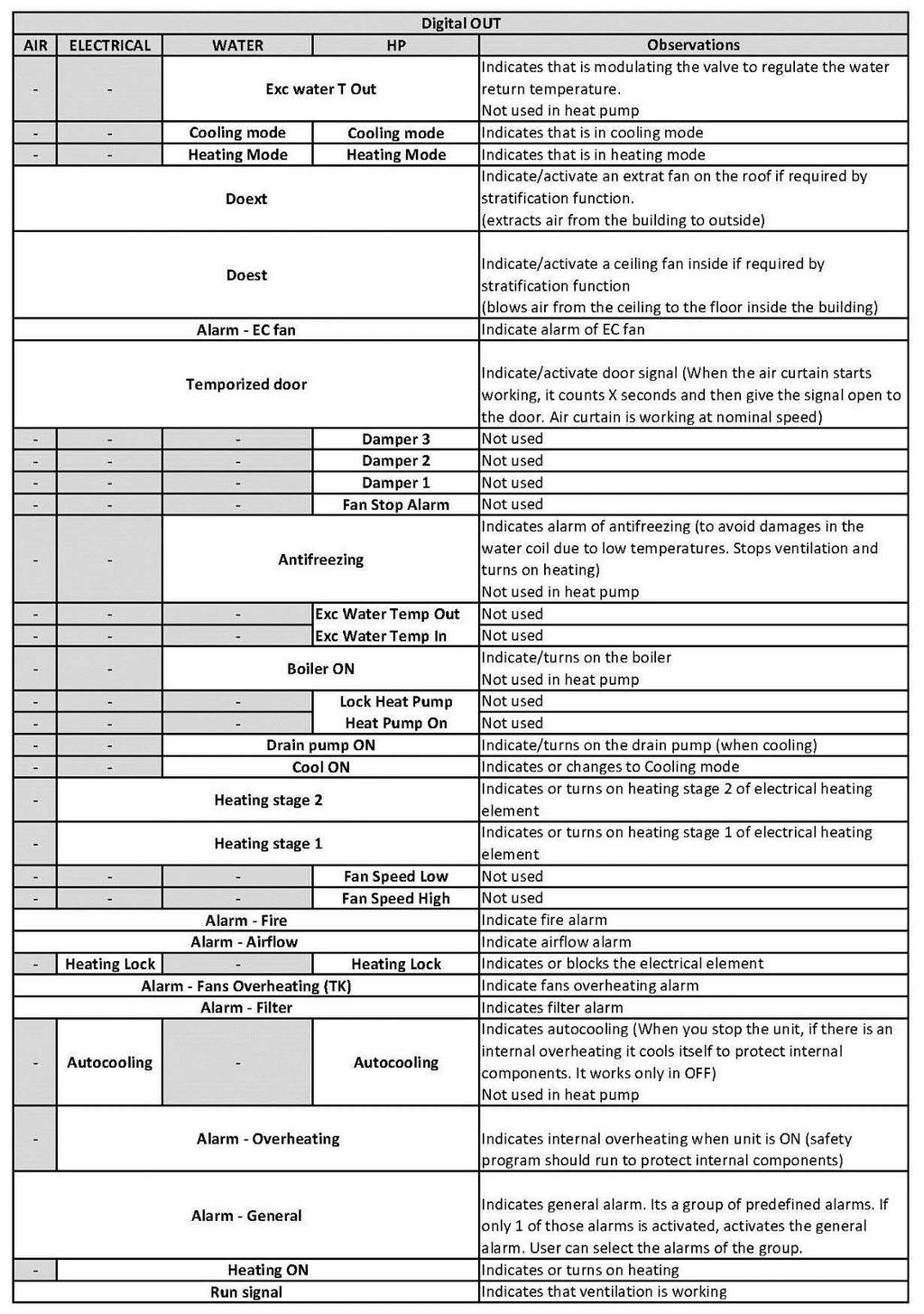
39 There is an ADVANCED MANUAL that explains deeply the functioning and configuration of all functions of: Digital IN Digital OUT Analog IN Analog OUT 39
40 BMS CONTROL Clever can be managed externally using: Digital/Analogic entrances or by via Modbus RTU Although you send wrong orders to the equipment, the unit will not allow combinations that can damage the internal components. The internal PCB has instructions to run the unit safety. For example, if you order to electrical heated air curtain go to 3 rd heating stage and 1 st ventilation speed, it will allow go to air speed 1 but heating will work at 1 st stage only (maximum allowed heating stage for first ventilation). If you stop the ventilation, the heating will also stop except: Anti-freezing sensor signal Minimum voltage for 0-10V proportional valves (avoid freezing) The minimum and maximum parameters (door open and door close) will be also respected. For instance, you define that maximum speed when the door is closed should be the 2 nd. Then if you order the 3 rd ventilation speed and door closes, it will change from 3 rd to 2 nd. If you open again the door it will go to the 3 rd. Digital/Analogic entrances: Clever has several digital IN and analogic IN to modify the functioning of the unit. At the wiring diagrams (beginning of this manual) you can see the default functions of each entrance. There are more functions than entrances, so you can select the most appropriate to cover your needs (advanced menu). All digital IN are NO (Normally Open), but you can change to NC (Normally Closed) at advanced menu. For example, here some default functions for air curtains: OFF Unit: Digital IN - DIN2 (free voltage, dry contact) OFF Heating: Digital IN - DIN3 (free voltage, dry contact) Temperature SET: Analog IN 0-10V (IN1) 0V 0-0,2V Do not modify the control setting 1V 0,3-1,2V = 19ºC 2V 1,3-2,2V = 20ºC 3V 2,3-3,2V = 21ºC 4V 3,3-4,2V = 22ºC 5V 4,3-5,2V = 23ºC 6V 5,3-6,2V = 24ºC 7V 6,3-7,2V = 25ºC 8V 7,3-8,2V = 26ºC 9V 8,3-9,2V = 27ºC 10V 9,3-10,2V = 28ºC Ventilation Speed: Analog IN 0-10V (IN2) If 5 speed air curtain, then: 0V 0-0,2V Do not modifies the control setting 2V 0,3-2,2V = Fan Speed 1 4V 2,3-4,2V = Fan Speed 2 6V 4,3-6,2V = Fan Speed 3 8V 6,3-8,2V = Fan Speed 4 10V 8,3-10,2V = Fan Speed 5 Heating Stage: Analog IN 0-10V - By default there is no entrance, but you can assign an entrance at advanced menu. All those orders given by digital/analogic inputs have priority to the programs functioning. For instance, if the program is running at maximum speed but you send 6V to (IN2), the unit will change to fan speed 3. It doesn t matter if the program conditions would change At this solution there is only 1 manager because all orders from BMS goes to the TFT and then to the Clever PCB. 40

41 Modbus RTU: Modbus system only allows 1 manager. So we should only send orders to the unit by BMS or TFT Clever (if both together there will be problems). To avoid communication troubles, you should use two different ports: TFT trough Modbus RTU1 and BMS at Modbus RTU2. See following diagram: Using the TFT you can select different baud rate at each port (by default is ). Before starting, be sure that port RTU2 has the same speed as BMS. If you want to send orders via Modbus you should: 1. Lock the TFT to avoid that nobody is sending also orders to the Clever (only 1 manager). You can lock using the same code of TFT or another different (then people won t be able to unlock from TFT as they won t know the code). 2. Stop the timer to avoid undesired ON Day/Night or OFF 3. Manage the unit: ON/OFF unit Select Energy Saving Mode (Comfort/Medium/Eco) Select the functioning mode: If MANUAL, you can select: Fan speed Heating stages Temperature SET If AUTOMATIC, you only can change the temperature SET If you want to stop managing the equipment from BMS and activate the Clever TFT to allow the people manage the unit, then you only have to unlock the TFT (and stop giving Modbus orders). If you have locked the controller using a different code than TFT, you have to unlock with the old TFT code (Known by people that uses TFT). 41

42 At the following page there are all the needed Modbus orders to manage the units. All changes will not be saved if the power supply stops. To avoid it, after any order you have to save the configuration. 42
43 CLEVER CONTROL - WALL MOUNTING INSTRUCTIONS Disassemble the casing using a flathead screwdriver (Press the 2 bottom fixation tabs) Separate the casing in 2 halves Identify wall connection. In case of not having a wall switch box, use Clever's wall support accessory. Mount the back cover inside the wall switch Connect RJ11 Cable to Clever's PCB connector, located in the front cover Assemble the front cover in 2 steps: Position it first on the top and press secondly on the bottom for clipping the tabs 43
CLEVER CONTROL - Version: V6.0
 CLEVER CONTROL - Version: V6.0 INSTALLATION AND FUNCTIONING MANUAL USER AND BASIC VERSION Please, read these instructions carefully before attempting installation Using a wrong tailor made RJ45 or RJ11
50110_HM-neoStat-2014_Layout 1 31/10/ :33 Page 1 neo
 neo Model: Available in : Sapphire Black and Glacier White 1 Wavin neo Table of Contents Product Image 1 Optional Features 19-22 Table of Contents 2 Re-calibrating the Thermostat 23 What is a Programmable
Rooftop Thermostat Controller Specification and Installation Instructions. Model TRT2422
 ºF / º C Rooftop Thermostat Controller Model TRT2422 Description The TRT2422 is a combination controller and thermostat with a built-in scheduler, which is designed for simple and accurate control of single
12V. Model: Available in : Sapphire Black and Glacier White. 2 Series
 Model: Available in : Sapphire Black and Glacier White 2 Series Table of Contents Product Image 1 Locking/Unlocking the neostat 19 Table of Contents 2 Frost Protection 20 What is a Programmable Room Thermostat?
Table of Contents. Product Image Table of Contents What is a Programmable Room Thermostat? Installation Procedure
 1 Model: 1 Table of Contents Product Image Table of Contents What is a Programmable Room Thermostat? Installation Procedure 1 2 3-4 5-6 Mode Select Pairing the ProTouch iq Hub Pairing the ProTouch iq What
Table of Contents. Model: Series. Available in : Sapphire Black and Glacier White. Product Image. 20 Table of Contents.
 1 Model: Available in : Sapphire Black and Glacier White Table of Contents Product Image 1 Frost Protection 20 Table of Contents 2 Power ON/OFF 21 What is a Programmable Room Thermostat? Installation Procedure
Model: 1 Series 12V. Available in: Sapphire Black and Glacier White
 Model: Available in: Sapphire Black and Glacier White 1 Series Table of Contents Product Image Table of Contents What is a Programmable Room Thermostat? Installation Procedure Mode Select Pairing the neohub
Model: Available in : Sapphire Black and Glacier White. 1 Series
 Model: Available in : Sapphire Black and Glacier White 1 Series Table of Contents Product Image 1 Frost Protection 20 Table of Contents 2 Power ON/OFF 21 What is a Programmable Room Thermostat? Installation
PRT-TS WiFi PRT-TS WiFi
 Model: PRT-TS WiFi Model: PRT-TS WiFi 1 Model: PRT-TS WiFi Table Of Contents Product Image 1 Frost Protection 16 Table of Contents 2 Heating ON/OFF 16 What is a Programmable Room Thermostat? Installation
Table of Contents. Product Image 1 Locking/Unlocking the neoair 24 Table of Contents 2 Frost Protection 25 What is a Programmable Room Thermostat?
 Table of Contents Product Image 1 Locking/Unlocking the neoair 24 Table of Contents 2 Frost Protection 25 What is a Programmable Room Thermostat? 3-4 Power ON/OFF 26 Holiday Programming 27 Installation
Model: Edge-HC. 1 edge-hc
 Model: Model: Edge-HC 1 edge-hc Table Of Contents Product Image Table of Contents Installation Procedure System Type LCD Display Power On/OFF Setting the Time & Date Mode Select Fan Speed Temperature Display
Model: Available in: Sapphire Black and Glacier White. 1 Series
 Model: Available in: Sapphire Black and Glacier White 1 Series Table of Contents Product Image Table of Contents What is a Programmable Room Thermostat? Installation Procedure Mode Select Pairing the neohub
Operation Manual Fighter ProVision Software. Version: 0.0 Revision: 1
 Operation Manual Fighter ProVision Software Version: 0.0 Revision: 1 TABLE OF CONTENTS 1. Introduction 5 2. Software Installation 5 3. PC Users 6 3.1 Introduction 6 3.2 Default Code 6 3.3 Edit PC User
INSTALLATION, OPERATION AND MAINTENANCE MANUAL. Air curtain SMART
 INSTALLATION, OPERATION AND MAINTENANCE MANUAL Air curtain SMART Read instructions carefully before attempting installation. Deliver this manual to end user. SECURITY ADVISE SYMBOLS Attention, Danger,
INSTALLATION, OPERATION AND MAINTENANCE MANUAL
 INSTALLATION, OPERATION AND MAINTENANCE MANUAL Air curtains ROTOWIND, INVISAIR Please, read these instructions carefully before attempting installation SECURITY ADVISE SYMBOLS Attention, Danger, Safety
General information. Technical data...2 General information...2. Description. Installation
 user manual Table of contents Technical data Technical data...2 General information...2 Installation...3 Navigation...3 First run...4 Main screen...6 Main menu...6 Time...7 Date...7 Calendar...7 Language...10
SIRe Competent Air Curtains Water With quick guide. SIReAC. For wiring diagram, please see p Original instructions
 Original instructions SIRe Competent Air Curtains Water With quick guide SIReAC SE... 2 GB... 19 DE... 36 FR... 54 For wiring diagram, please see p.71-73 For more languages, please see www.frico.se SIRe
INSTALLATION, OPERATION AND MAINTENANCE MANUAL
 INSTALLATION, OPERATION AND MAINTENANCE MANUAL Air Curtains MAX Please, read these instructions carefully before attempting installation SECURITY ADVISE SYMBOLS Attention, Danger, Safety Advice! Danger
Operating Instructions Model: PRT-TS WiFi RF. 01/13 Version 1 Ref: PRT-TSWIFI RF
 Operating Instructions Model: PRT-TS WiFi RF 01/13 Version 1 Ref: PRT-TSWIFI RF Contents Page Setting up your WiFi Thermostat 2-6 Remote Connection Setup 6-8 Pairing with the Receiver 8-12 Display Symbols
Touch Screen Thermostat. MTSC/SUPER/CO2, MTSC24/SUPER/CO2 Series. MTS/SUPER/CO2, MTS24/SUPER/CO2 Series. Owner s manual and technician settings
 Touch Screen Thermostat MTSC/SUPER/CO2, MTSC24/SUPER/CO2 Series MTS/SUPER/CO2, MTS24/SUPER/CO2 Series Owner s manual and technician settings Rev. 2.4 Index 1. Owner s Manual... 3 1.1 Quick Guide. 4 1.2
VAV Thermostat Controller Specification and Installation Instructions. Model TRO24T4XYZ1
 Model TRO24T4XYZ1 Description The TRO24T4XYZ1 is a combination controller and thermostat. The VAV Thermostat Controller is designed for simple and accurate control of any variable air volume box in a number
Please read this manual carefully before installation and use.
 Doylestown, PA 18902 USA Phone: 215-766 1487 - Fax: 215-766 1493 Email: support@scillc.com - www.scillc.com FMT-24-SUPER-PROG With freeze protection Owner s Manual Installation and Operating Instructions
REMOTE CONTROL FOR CHILLER MYCHILLER
 REMOTE CONTROL FOR CHILLER MYCHILLER GENERAL FEATURES... 3 MAIN FUNCTIONS AND EQUIPMENT:... 3 LCD DISPLAY... 4 KEYBOARD... 5 BOARD CONFIGURATION... 7 LIST OF MAIN PARAMETERS... 7 CONFIGURATION OF MAIN
INSTALLATION, OPERATION AND MAINTENANCE MANUAL
 INSTALLATION, OPERATION AND MAINTENANCE MANUAL Air Curtains OPTIMA Please, read these instructions carefully before attempting installation SECURITY ADVISE SYMBOLS Attention, Danger, Safety Advice! Danger
User Manual. Dryer Controller M720
 User Manual Dryer Controller M720 Hardware version 1.00 Software version 1.00 Preliminary version Manual M720 Dryer controller Page 1 of 42 Document history Preliminary version: - Created in April, 2009
INSTALLATION, OPERATION AND MAINTENANCE MANUAL
 INSTALLATION, OPERATION AND MAINTENANCE MANUAL Air Curtains RUND Please, read these instructions carefully before attempting installation SECURITY ADVISE SYMBOLS Attention, Danger, Safety Advice! Danger
Dryer Controller M720
 User Manual Dryer Controller M720 Hardware version 2.00 Software version 2.00 Manual M720 Dryer controller Page 1 of 60 Document history Preliminary version: - Created in April, 2009 Hardware Version 2.00,
User manual CLIMATIC 200/400 - Controller. Providing indoor climate comfort
 User manual CLIMATIC 2/4 - Controller Providing indoor climate comfort MUL35E-56 9-26 INDEX CONTENTS PAGE INDEX 1 GENERAL DESCRIPTION 2 THE KEYPAD, Climatic 2 3 THE KEYPAD, Climatic 4 4 THE KEYPAD REMOTE
Halton SAFE / 7.14 user guide and installation instructions
 Halton SAFE / 7.14 user guide and installation instructions VERIFIED SOLUTIONS BY H A LTO N Enabling Wellbeing Table of contents 1 System description 3 2 User Accounts 4 3 Main menu 7 3.1 Main menu - Change
Networkable Fan Coil Controller Specification and Installation Instructions
 Controller Models EFCB10T-OE1 (24Vac / 0 relays) EFCB12T-OE1 (240Vac / 0 relays) EFCB10TU4-OE1 (24Vac / 4 relays) EFCB12TU2-OE1 (240Vac / 2 relays) EFCB12TU4-OE1 (240Vac / 4 relays) TFL Series Thermostat
ModSync Sequencing System Installation & Operation Manual. For use with Fulton Steam Boilers.
 ModSync Sequencing System Installation & Operation Manual For use with Fulton Steam Boilers. Revision 3.0 8/21/2008 - 2 - Table of Contents Introduction Page 4 Features Page 4 Sequence of Operation Page
Operating Instructions Model: PRT-RP Version 3. 05/11 Revision 2 Ref: PRTRP
 Operating Instructions Model: PRT-RP Version 3 05/11 Revision 2 Ref: PRTRP Contents Page What is a programmable thermostat? 2-4 Installation 5-6 Icons explained 6 Temperature Display 7 Setting the Clock
Touch Screen Thermostat. MTSC/SUPER, MTSC24/SUPER Series. MTS/SUPER, MTS24/SUPER Series. Owner s manual and technician settings
 Touch Screen Thermostat MTSC/SUPER, MTSC24/SUPER Series MTS/SUPER, MTS24/SUPER Series Owner s manual and technician settings -2 - Index 1. Owner s Manual... 4 1.1 Quick Guide. 4 1.2 Turning the unit ON
ETN-24-SUPER-PROG (US Program - Celsius)
") Meitavtec Ltd (Contel group) Tel: 972 (3) 962 6462 Fax: 972 (3) 962 6620 www.meitavtec.com support@meitavtec.com ETN24SUPERPROG (US Program Celsius) Owner s Manual Installation and Operating Instructions
Meitavtec Ltd (Contel group) Tel: 972 (3) 962 6462 Fax: 972 (3) 962 6620 www.meitavtec.com support@meitavtec.com ETN24SUPERPROG (US Program Celsius) Owner s Manual Installation and Operating Instructions
INSTALLATION, OPERATION AND MAINTENANCE MANUAL
 INSTALLATION, OPERATION AND MAINTENANCE MANUAL Air Curtains: RECESSED WINDBOX (M, ECM, G, ECG), RECESSED COMPACT (M, ECM, G, ECG), RECESSED DAM (M, ECM, G, ECG) Please, read these instructions carefully
FLOW CONTROLLER TYPE S/601
 Checked Version Release date QA V4.2.6 F1 F2 EN 26.01.2012 Manual FLOW CONTROL FLOW CONTROLLER TYPE S/601 MODELS F1 AND F2 INTRODUCTION Thank you for using the S/601 flow and batch control series. This
ATC32U03 igate Communicating, Programmable Thermostat
 ATC32U03 igate Communicating, Programmable Thermostat User Manual 97B0055N02 Rev.: 11/3/17 Table of Contents Section Title Page Menu Navigation Shortcuts 3 1.0 Operating Mode Selection 3 2.0 Temperature
Instructions for the hand-held micro terminal of the fan motor control system, TBLZ-2-75 SILVER C
 Instructions for the hand-held micro terminal of the fan motor control system, TBLZ-2-75 SILVER C 1. General The hand-held micro terminal is used for setting the motor parameters of the SILVER C. 2. Installation
Refrigerated air dryers
 Refrigerated air dryers OPERATING AND MAINTENANCE MANUAL Original instructions 38178800319 OPERATING AND MAINTENANCE MANUAL - Contents 1 CONTENTS CONTENTS... 1 Chapter 1 IDRY ELECTRONIC CONTROLLER...
NEW RANGE OF WARM AIR CURTAINS
 NEW RANGE OF WARM AIR CURTAINS stay connected and informed in real time www.france-air.com CONTENTS SELECTION GUIDE 3 HARMONY ONE EVO Compact single-phase warm air curtain 4 REGULATION 5 HARMONY Visible
LCF Touch Modbus Datasheet Application Security Advice Caution
 LCF Touch Modbus Electronic Fan Coil Thermostat with Touch Display (Flush mounting) Datasheet Subject to technical alteration Issue date: 3.11.214 Application Modern design flush mounting fan coil room
User Guide. Color Touchscreen Programmable Residential Thermostat. ComfortSense Model: 13H /2015 Supersedes 7/2015
 User Guide Color Touchscreen Programmable Residential Thermostat ComfortSense 7500 Model: 13H14 507503-01 10/2015 Supersedes 7/2015 TABLE OF CONTENTS Features... 2 Temperature Dial Indicator... 3 Home
DPC-1 Programmable digital thermostat with communication Versión 2.0. Technical Information. Ref: N
 DPC-1 Programmable digital thermostat with communication Versión 2.0 Ref: N-27360 1108 Technical Information I S O 9 0 0 1 ER-0028/1991 Johnson Controls Manufacturing España, S.L. is participating in the
Underfloor Heating Programmable Thermostat
 Underfloor Heating Programmable Thermostat t: 093 4906 m: 0794 69635 w: www.gs-ufh.co.uk e: gs@warmfloors.co.uk POWER CLOCK H A DOWN UP TO CHANGE THE TIMINGS AT ANY STAGE DURING THE PROCESS YOU CAN PRESS
Important Supplementary Manual to the main Ezeio manual. 5. Section 2a: Introducing the 2400 input and output expansion field stations.
 1 P age Ezeio v9-120317 Eze Cloud Based Monitoring Systems. Created by Intech Instruments Ltd December 2014 Important Supplementary Manual to the main Ezeio manual. Ezeio Controller and the 2400-A16 input
HIGH EFFICIENCY FIRETUBE CONDENSING GAS BOILER
 This manual must be left with owner and should be hung on or adjacent to the boiler for reference. US HIGH EFFICIENCY FIRETUBE CONDENSING GAS BOILER MODELS CHS-85 through CHS-399 APPENDIX A CONTROLLER
DAP III Zone Master User s Guide
 DAP III Zone Master User s Guide Data Aire, Inc. 230 West BlueRidge Avenue Orange, California 92865 Document Number 600-000-788 March 2010 Revision 1.0 Document # 600-000-788 1 Overview The Data Aire DAP
INSTALLATION, OPERATION AND MAINTENANCE MANUAL
 INSTALLATION, OPERATION AND MAINTENANCE MANUAL Air Curtains: WINDBOX (M, ECM, G, ECG), KOOL (M, ECM, G, ECG), DECO (M, ECM, G, ECG), DAM (M, ECM, G, ECG) Please, read these instructions carefully before
Refrigeration Controller Operator s Manual (HRC) PO Box 6183 Kennewick, WA
 PO Box 6183 Kennewick, WA") Refrigeration Controller Operator s Manual (HRC) PO Box 6183 Kennewick, WA 99336 www.jmcvr.com 1-509-586-9893 Table of Contents TABLE OF FIGURES...1 OVERVIEW OF THE HRC CAPABILITIES...2 INSTALLATION AND
Refrigeration Controller Operator s Manual (HRC) PO Box 6183 Kennewick, WA 99336 www.jmcvr.com 1-509-586-9893 Table of Contents TABLE OF FIGURES...1 OVERVIEW OF THE HRC CAPABILITIES...2 INSTALLATION AND
Drayton Digistat +3RF
 Drayton Digistat +3RF Programmable Room Thermostat Wireless 5-2 Day / 7 Day Model: RF701/22092 Power Supply: Battery - Thermostat Mains - Digistat SCR Invensys Controls Europe Customer Service Tel: 0845
Model: Touch-RF. 1 Wireless Series
 Model: Touch-RF Model: Touch-RF 1 Wireless Series Table Of Contents Product Image 1 Locking the Keypad 18 Table of Contents 2 Temperature Control 19 What is a Programmable Room Thermostat? 3-4 Hot Water
S/601 Controller Installation Manual
 Checked Version Release date QA V4.6.5 PC1 EN 02.07.2012 2011 S/601 Controller Installation Manual FLOW CONTROL PC1 - Pump controller Introduction Thank you for using the S/601 flow, batch and pump control
THERMOMATIC EC HOME. Installation and User Guide, version 1.0
 THERMOMATIC EC HOME Installation and User Guide, version 1.0 Table of contents: 1. Overview, dimensions, choice of control functions, extras, pages 2-3 2. Delivery scope, page 4 3. Start Guide, pages 5-7
Table of Contents. SLIMLINE Series MODEL: SLIMLINE
 Table of Contents Product Image 1 Table of Contents 2 What is a Programmable Room Thermostat? 3-4 Installation Procedure 5-6 LCD Display 7-8 Setting the Clock 9 Temperature Display 10 Setting the Comfort
AC&R Controller RWR Basic Documentation VR2002 for water to water heat pump units
 AC&R Controller RWR470.10 Basic Documentation VR2002 for water to water heat pump units Table of Contents 1 Summary---------------------------------------------------------------------------------------4
Photo 5 Photo 6 Note: Once you connected the dehumidifier to the local network you can install the app on any other mobile phones and use Scan QR key
 1. Your dehumidifier also has the ability to be controlled over WIFI from your smart phone. The first step is to download the correct app. The IOS version is available from Itunes by searching for "IQSmart"
SIRe Advanced Air Curtains Electric With quick guide. SIReAA GB DE FR For wiring diagram, please see last pages. ES
 Original instructions SIRe Advanced Air Curtains Electric With quick guide SIReAA SE... 2 GB... 22 DE... 42 FR... 62 ES... 82 IT... 102 NL... 122 NO... 142 PL... 162 RU... 181 For wiring diagram, please
INSTALLATION & USER MANUAL
 INSTALLATION & USER MANUAL HC Digital Automatic Humidistat (Y3760) CONTROLS 506808-01 3/2016 Supersedes 6/2011 picture goes here THIS MANUAL MUST BE LEFT WITH THE HOMEOWNER FOR FUTURE REFERENCE NOTICE
Lyric T6 & T6R Smart Thermostat
 Lyric T6 & T6R Smart Thermostat EN User Guide Lyric T6 Programmable Thermostat Lyric T6R Wireless Programmable Thermostat Lyric T6 & T6R Smart Thermostat Features Connects to the Internet so you can control
ATC32U01 igate Communicating, Programmable Thermostat
 ATC32U01 igate Communicating, Programmable Thermostat User Manual 97B0055N02 Rev.: 7/2/12 Table of Contents Section Title Page Menu Navigation Shortcuts 3 1.0 Operating Mode Selection 3 2.0 Temperature
VERSO-P, VERSO-R Series Air Handling Units with C3 Control System Electrical Installation and Operation Manual
 VERSO-P, VERSO-R Series Air Handling Units with C3 Control System Electrical Installation and Operation Manual EN Table of Contents 1. INSTALLATION MANUAL...3 1.1. Air Handling Units Sections Connection...3
DIGISTAT OPTIMISER PROGRAMMABLE 7 DAY ROOM THERMOSTAT SYSTEM. Radio frequency controlled programmable room thermostat
 DIGISTAT OPTIMISER PROGRAMMABLE 7 DAY ROOM THERMOSTAT SYSTEM Radio frequency controlled programmable room thermostat FOR GREENSTAR 25 HE and GREENSTAR 30 HE MODELS Hol Man Auto Day SIGNAL HEATING ON OVERRIDE
PowerLogic ION Setup Meter Configuration Software Configuration Guide
 PowerLogic ION Setup Meter Configuration Software Configuration Guide 70002-0293-03 12/2010 Conventions Used in this Manual This section describes the symbols and terminology used in this guide. Symbols
Model: Touch-RS. 1 Touch-RS
 Model: Touch-RS Model: Touch-RS 1 Touch-RS Table of Contents Product Image 1 Temperature Hold 15 Table of Contents 2 Holiday Programming 16 What is a Programmable Room Thermostat? Installation Procedure
Danfoss gas detection units
 Data sheet Danfoss gas detection units Types GD Premium, Premium+, Premium Duplex, Premium Remote, Premium Flex and Premium Uptime The Premium line gas detection units are used for monitoring and warning
MAKING MODERN LIVING POSSIBLE. TP7001 Range Electronic 7 Day Programmable Room Thermostat. User Guide. Danfoss Heating
 MAKING MODERN LIVING POSSIBLE TP7001 Range Electronic 7 Day Programmable Room Thermostat Danfoss Heating User Guide TP7001 Electronic 7 Day Programmable Room Thermostat For a large print version of these
OWNER OPERATION MANUAL FOR USER 2.0
 OWNER OPERATION MANUAL FOR USER.0 Contents kumo cloud... Quick Setup... Get Started... Download the App... Create an Account... Control... Whole or Individual Zone... Temperature... Cool, Heat and Other
User start guide Connected wireless room thermostat Logic Combi C / Vogue Gen 2 Combi Logic Max Combi C / Vogue Max Combi Vogue Combi C / Logic Combi
 User start guide Connected wireless room thermostat Logic Combi C / Vogue Gen Combi Logic Max Combi C / Vogue Max Combi Vogue Combi C / Logic Combi Contents Introduction... Ideal Touch kit contents...
ComfortSense 7500 Thermostat. User Guide
 ComfortSense 7500 Thermostat User Guide 507503-02 6/2018 Supersedes 5/2017 Table of Contents Features...2 Home Screen Temperature Indicator...3 Home Screen Information...3 Operating Mode Selection...6
T600MEP-2 Programmable Economizer Thermostat
 Installation Instructions Issue Date January 19, 2005 T600MEP-2 Programmable Economizer Thermostat Application The T600MEP-2 is a programmable thermostat for control of single- or two-stage unitary rooftop
TECHNICAL MANUAL CVM 20 C 5005 CV/04-99 GB
 Summary 1 CONNECTIONS... 3 1.1 TEMPERATURE PROBES...3 1.2 LOW VOLTAGE DIGITAL INPUTS...3 1.3 LIVE DIGITAL INPUTS...4 1.4 RELAY OUTPUTS...5 2 POWER SUPPLY... 6 3 SERIAL CONNECTIONS... 6 4 SOFTWARE... 7
Model: Slimline-N. 1 Slimline Series
 Model: Slimline-N Model: Slimline-N 1 Slimline Series Table of Contents Product Image Table of Contents What is a Programmable Room Thermostat? Installation Procedure LCD Display Operating Mode Setting
Pioneer Z100 Smart Thermostat Operating and Installation Manual
 Pioneer Z100 Smart Thermostat Operating and Installation Manual AW000515-B Page 2 Operating and Installation Manual Congratulations on the purchase of your new thermostat. It has been designed for easy
Fan Coil Thermostat Controller Specification and Installation Instructions. Model TFHB24F3XYZ1 with External Humidity Sensor and BACnet Communication
 Model TFHB24F3XYZ1 with External Humidity Sensor and BACnet Communication Description The TFHB24F3XYZ1 is a fully configurable controller designed specifically for 2 pipe and 4 pipe fan coil applications.
INSTALLATION AND OPERATION MANUAL
 INSTALLATION AND OPERATION MANUAL Installation and operation manual Table of contents Page 1. Supplied accessories and intended use... 1 2. General layout and setup of a system... 2 3. Installation...
BLAUAIR AUTOMATIC CONTROL SYSTEM
 BLAUAIR AUTOMATIC CONTROL SYSTEM S30 (KVENT, TH-TUNE) S31 (KVENT) S32 (KVENT, PGDE) EN USER S MANUAL CONTENTS Safety requirements... 3 Purpose... 4 Technical data... 5 Installation and set-up... 6 Control...
2018 thesimple, Inc.
 TM User Guide 2018 thesimple, Inc. Introduction The Simple thermostat supports supports 2 heating stages and 2 cooling stages for conventional systems, and 2 heating/cooling stages for heat pumps, with
Weekly thermostat for boilers Galan - regulator for management of heating elements and circuit SolarSentinel-DBTW Users guide.
 Weekly thermostat for boilers Galan - regulator for management of heating elements and circuit SolarSentinel-DBTW Users guide. SHORT DESCRIPTION: 1. Device is applicable to: - Burners; - Electric boiler;
Smart Thermostat. User Guide
 Smart Thermostat User Guide WELCOME 1 GET STARTED Self-installation Professional Installer OR Self-installation Get customised step-by-step instructions for your specific heating system online Professional
Installer Manual KNX Touchscreen Thermostat
 Installer Manual 02952 KNX Touchscreen Thermostat Index GENERAL FEATURES AND FUNCTIONALITY from page 5 ETS PARAMETERS AND COMMUNICATION OBJECTS from page 7 COMMUNICATION OBJECTS GENERAL FEATURES AND FUNCTIONALITY
WATER HEATER ELECTRONIC CONTROLLER USER MANUAL
 WATER HEATER ELECTRONIC CONTROLLER USER MANUAL UPPER LED READOUT LED ICONS LOWER LED READOUT PVI INDUSTRIES, LLC - Fort Worth, Texas 76111 - Web www.pvi.com - Phone 1-800-433-5654 Page 1 / 7 PV500-40 03/17
Netatmo Thermostat user manual Netatmo Thermostat V1.0 / December 2013 You can nd an interactive version of this user manual in your Netatmo app
 Netatmo Thermostat user manual Netatmo Thermostat V1.0 / December 2013 You can nd an interactive version of this user manual in your Netatmo app (iphone/ipad/android). It is also available for computer
Modbus RTU RS485 Manual
 Modbus RTU RS485 Manual AUTOMATED FUEL MAINTENANCE SYSTEMS FTI-5A, FTI-10A, FTI-20A FUEL TECHNOLOGIES INTERNATIONAL 06/10/2014 Rev B - Fuel Technologies - Modbus The Modbus Communications Setup Button
EXcon zone control. Control for up to 4 individual zones _ fm. EXHAUSTO A/S Odensevej 76 DK-5550 Langeskov
 3005925_2018-02-05.fm EXcon zone control Control for up to 4 individual zones EXHAUSTO A/S Odensevej 76 DK-5550 Langeskov Tel. +45 65 66 12 34 Fax +45 65 66 11 10 exhausto@exhausto.dk www.exhausto.dk OJ-Air2
INSTALLER S & OWNER S MANUAL
 INSTALLER S & OWNER S MANUAL HVAC INSTALLER: PLEASE LEAVE MANUAL FOR HOMEOWNER DEH 3000R Part No. 4028407 Dehumidifier & Ventilation System Controller 4201 Lien Road, Madison, WI 53704 TOLL-FREE (800)-533-7533
INSTRUCTION MANUAL REMOTE CONTROL DEVICE EASYREMOTE
 INSTRUCTION MANUAL REMOTE CONTROL DEVICE EASYREMOTE Technical features Guide to LCD symbols Guide to keys Technical features Supply by communication bus Number of temperature levels 2 (DAY / NIGHT) Temperature
/18 (JRK) MTD User Manual OJ Electronics A/S
 MTD User Manual OJ Electronics A/S") 67772 02/18 (JRK) MTD3-1999 User Manual Table of Contents Introduction.................................. 3 Menu Overview................................ 4 Icons....................................... 5
67772 02/18 (JRK) MTD3-1999 User Manual Table of Contents Introduction.................................. 3 Menu Overview................................ 4 Icons....................................... 5
ETNC24-FC-BAC-PIR-01 Owner s manual & Technician Settings
 ETNC-FC-BAC-PIR- Rev. Index Operating instructions....- Turning the thermostat and OFF Selecting temperature scale Adjusting the Set point temperature (for set point and set points configurations) Selecting
Model : PRT-EN Model: PRT-EN1
 Model: PRT-EN Model: PRT-EN 1 Model: PRT-EN Table of Contents Product Image Table of Contents What is a Programmable Room Thermostat? Installation Procedure LCD Display Setting the Clock Temperature Display
CONTROLS WI-FI THERMOSTAT. icomfort Wi-Fi Flex Thermostat PRODUCT SPECIFICATIONS
 CONTROLS WI-FI THERMOSTAT PRODUCT SPECIFICATIONS icomfort Wi-Fi Flex Thermostat Bulletin No. 210725 December 2015 The icomfort Wi-Fi Flex Thermostat recognizes and connects conventional heating/cooling
Product Manual SZ1009
 Product Manual SZ1009 Conventional Heating & Cooling Thermostats with Heat Pump Mode Communicating Thermostats Description The SZ1009 is a microprocessor-based mable thermostats designed for conventional
User s Manual
 997-060180-4e User s Manual 8403-060 Menu Driven Display 1120-445 I. CONTROLLER OPERATION ADJUSTING TEMPERATURE (Temporary Override when in Programmable mode) 1. Before you can adjust the temperature,
GreenCon On/Off Room Thermostat
 Description Features: Scandinavian design with white backlight; User-friendly interactive interface; Room temperature display and settings; 12 or 24 hour clock display and settings; Three-speed manual/automatic
IntelliSync Thermostat / Mobile App Frequently Asked Questions
 IntelliSync Thermostat / Mobile App Frequently Asked Questions This FAQ page addresses the most common questions on Deriva IntelliSync. Why bother setting a heating and cooling schedule? What is ENERGY
Model: Slimline-RF. 1 Slimline Series
 Model: Slimline-RF Model: Slimline-RF 1 Slimline Series Table of Contents Product Image 1 Holiday Programming 22 Table of Contents What is a Programmable Room Thermostat? 2 3-4 Setting the Hot Water Switching
GreenCon On/Off Room Thermostat
 Description Features: Scandinavian design with white backlight; User-friendly interactive interface; Room temperature display and settings; 12 or 24 hour clock display and settings; Three-speed manual/automatic
HMC300. Control unit. Operating Instructions. EMS plus (2014/10) O
 O") HMC300 Control unit EMS plus 6 720 808 471-00.1O Operating Instructions 6 720 813 192 (2014/10) Contents Contents Key to symbols and safety instructions................3 1.1 Key to symbols...........................
HMC300 Control unit EMS plus 6 720 808 471-00.1O Operating Instructions 6 720 813 192 (2014/10) Contents Contents Key to symbols and safety instructions................3 1.1 Key to symbols...........................
Peak Partners Web-Programmable Thermostat Homeowner s Manual. Look inside for a complete guide to the setup and operation of your new thermostat.
 Peak Partners Web-Programmable Thermostat Homeowner s Manual Look inside for a complete guide to the setup and operation of your new thermostat. Table of Contents Step 1: Getting Started...4-6 A. Thermostat
TPOne-B. Electronic Programmable Room Thermostat. Installation Guide. Danfoss Heating
 TPOne-B Electronic Programmable Room Thermostat Danfoss Heating Installation Guide TPOne is an intelligent programmable heating control made easy. TPOne includes features which are designed to save energy.
Programmable Thermostat
 Set & $ave Programmable Thermostat Installation and Operation Manual English Model 44360 Form# 42710-01 20091204 2009 Hunter Fan Co. 2 Table of Contents Important Information... 5 Tools... 6 Uninstalling