DERWENT PRESTIGE MAY 2004
|
|
|
- Alicia Lucas
- 6 years ago
- Views:
Transcription
1 MAY 2004
2 INDEX Section 1 Fig 1 - GeneralData & Dimensions 1 Table 1 - BoilerDimensions 1 Table 2 - Connections 1 Table 3 - TechnicalData 5 to 12 Section 2 Table 4 - TechnicalData 13 to 22 Section 3 Fig 2 - SteelBase Strip Details 5 - Clearances & BurnerInfo 5 Section 2 - GeneralInformation 6 - Standard Supply 6 - Controls 6 - Shipping & Packaging 6 - Instalation - BoilerSiting & Base 7 Section 3 - Ventilation 8 - Flue Size Considerations 8 - Common Flue Systems 9 - W atercirculation systems 9 - BoilerProtection 9 - System W aterquality 9 - Sealed Systems 9 Section 4 - BoilerErection- Risk Assessmen 10 - ManualHandling 10 - PersonalProtective Equipment 10 - Confined Spaces 10 - ElectricalSafety 10 - Packing Details 10 - C.O.S.H.H 11 - Erection/Assembly Checklist 11 - HeatExchangerAssembly 12 - Assembly ofboilerblock 12 Fig 3 - Section Assembly 1 12 Fig 4 - Stud Fixing 12 Fig 5 - Section assembly 2 12 Fig 6 - Section assembly 3 12 Fig 7 - Section Assembly 4 12 Fig 8 - Sealing Cord 12 Fig 9 - Section Assembly Fiting the Seals 13 Fig 10 - Section Assembly 6 13 Fig 11 - Section Assembly 7 13 Fig 12 - Section Assembly 8 13 Fig 13 - Section Assembly 9 13 Fig 14 - Section Assembly Fig 15 - Section assembly Combustion chamberbase Plate 14 - Hydraulic TestofBoiler 14 Fig 16 - Ceramic FeltAssembly 14 - Instaling Multiple Unassembled Boilers14 Fig 17 - Minimum Clearance Multiple Boilers 14 - Fiting ofburnerassembly 15 - BoilerMaintenance 16 - Fiting Flue Hood & Burners 17 - Combustion ChamberFrontPlate 17 - Handing 17 Fig 18 - Flue Hood Assembly 17 Fig 19 - Flue Hood Assembly 17 - Assembly ofcasing 5 to 8 Section 18 Fig 20 - GeneralArrangementofCasing (5 to 8 Section) 18 Fig 21 - GeneralArrangementofCasing (5 to 8 Section) 19 - Assembly ofcasing 9 to 22 Section 20 Fig 22 - GeneralArrangementofCasing (9 to 22 Section) 20 Fig 23 - GeneralArrangementofCasing (9 to 22 Section) 21 Fig 24 - GeneralArrangementofThermostat Pocket 22 - Connecting the W atersystem 22 - Connecting the ElectricalSupply 22 - Connecting the Flue 22 - BoilerDisassembly 22 - Connecting the PilotLine 23 Fig 25 - GeneralArrangementofPilotBurner 23 - Connecting the Gas Supply 24 Fig 26 - ControlPanelConfiguration 24 - BoilerControls 24 - Commissioning Check List 25 - Contravention ofregulations 25 - Commissioning 25 - Emergency Instructions 26 - Pre-Lighting 26 - Commissioning Live Run 27 - Seting the Gas valve 5 to 11 Section 27 Fig 27 - Dungs MB ZRDLE 28 - Seting the Gas Valve 12 to 22 Section28 Fig 28 - Gas Train 12 to 22 Section 28 - Ionisation CurrentCheck 28 - Flue Spilage Test 28 - Ventilation Checks 29 - Operation ofancilary Controls 29 Fig 29 - Controls & High/Low Thermostats 29 - W aterflow Switch 29 - BoilerMaintenance 29 - BoilerCleaning 30 - FaultFinding 30 - BurnerLockout 31 - Check List 32 - ComponentReplacement 33 Section 5 Fig 30 - Gas Train Configuration 34 Fig 31 - Pump Overrun 35 Fig 32A - BoilerW iring Diagram 36 - Legend forw iring Diagram 36 Fig 32B - BoilerW iring Diagram 37 Section 6 PartNos Fig 33 - BoilerBody 38 Fig 34 - BurnerAssembly 41 Fig 35 - Casing Assembly 44 Fig 36 - Flue Box 46 Fig 37 - ControlPanel 48 Fig 38 - Gas Valve 50
3 POTTERTON COMMERCIAL PRODUCTS DIVISION SECTION 1 INSTALLATION,OPERATION & MAINTENANCE MANUAL PAGE 1 DERW ENT PRESTIGE Fig.1 - General Data & Dimensions (mm) (NOT TO SCALE) B C ØF (OD) POTTERTON D Drain tap BSP ¾ Gas Inlet G Flow Options Return Options 1073 E A 60 Table 1 - Boiler Dimensions Sections Output kw A mm B mm C mm D mm E mm ** 910** ØF mm G mm **From the 12 section the gas connection & return connection cannot be made on the same side. Table 2 - Connections Water 1 ½ BSP 2 BSP Drain Gas ¾ BSP 3/4 BSP drain cock supplied 2 ½ Flange (PN6 DN65)* 1 BSP 1 ½ BSP 2 BSP * 20 & 22 Section flow and return are screwed flanged connections - mating flanges supplied Note:only one flow and one return connection can be used. Refer to page 18 for details on handing options for boiler flow,return and gas connections.
4 SECTION 1 PAGE 2 POTTERTON COMMERCIAL PRODUCTS DIVISION TABLE 3 - Technical Data (5 to 12 section) Number of Sections CE Certification Number 0063AS3312 Output kw Fuel Consumption (G20) m³/hr Input (Nett) kw Input (Gross) kw Nominal Gas Inlet Pressure mbar 20 Burner Manifold Pressure mbar High Fire 16.5 / Low Fire 10.6 Burner Injector Size mm 3.2 Maximum Design Pressure Bar 5 2 Minimum Operating Pressure Bar 0.5 (0.1 bar Available on request) 3 Nominal Flue Connection Size Ømm Internal Diameter of Diverter Socket to BS 835 Ømm Flue Gas Volume m³/hr Flue Draught Requirements High Level Natural Ventilation to BS 6644 Low Level Natural Ventilation to BS 6644 cm² cm² 1-4 mm ALL SIZES Mechanical Inlet to BS 6644 m³/sec Water Connection Size BSP 1 1/2" 2" 8 Water Flow at 11 C t Min Water Flow at 25 C t lit/sec lit/sec Hydraulic Resistance at 11 C t kpa Cold Feed Size to BS 6644 Minimum Bore Open Vent Size to BS 6644 Minimum Bore Safety Valve Size to BS 6644 Nominal Size mm mm mm Maximum Flow Temperature C Minimum Return Temperature C C C (40 C with direct compensation) 11 Dry Weight kg Water Content kg Power Requirements V 50Hz 1Ph - Isolator and 6.3A fuse required For metric to imperial conversions refer to conversion chart inside back cover
5 POTTERTON COMMERCIAL PRODUCTS DIVISION SECTION 1 PAGE 3 TABLE 4 - Technical Data (13 to 22 section) Number of Sections CE Certification Number 0063AS3312 Output kw Fuel Consumption (G20) m³/hr Input (Nett) kw Input (Gross) Nominal Gas Inlet Pressure mbar 20 Burner Manifold Pressure mbar High Fire 16.5 / Low Fire 10.6 Burner Injector Size mm 3.2 Maximum Design Pressure Bar 5 2 Minimum Operating Pressure Bar 0.5 (0.1 bar Available on request) 3 Nominal Flue Connection Size Ømm Internal Diameter of Diverter Socket to BS 835 Ømm Flue Gas Volume m³/hr Flue Draught Requirements High Level Natural Ventilation to BS 6644 Low Level Natural Ventilation to BS 6644 cm² cm² 1-4 mm ALL SIZES Mechanical Inlet to BS 6644 m³/sec Water Connection Size BSP 2" Flanged 2 ½ 8 Water Flow at 11 C t Min Water Flow at 25 C t lit/sec lit/sec Hydraulic Resistance at 11 C t kpa Cold Feed Size to BS 6644 Minimum Bore mm Open Vent Size to BS 6644 Minimum Bore mm Safety Valve Size to BS 6644 Nominal Size mm Maximum Flow Temperature C Minimum Return Temperature C C C (40 C with direct compensation) 11 Dry Weight kg Water Content kg Power Requirements See Page 4 for explanatory notes 230V 50Hz 1Ph - Isolator and 6.3A fuse required Conversion table on inside of back cover
6 SECTION 1 PAGE 4 POTTERTON COMMERCIAL PRODUCTS DIVISION 1. FUEL CONSUMPTION Gas fuel consumption is based on natural gas with a gross calorific value of 38.6 MJ/m 3. The gas rate should be corrected for the meter supply pressure particularly on high pressure supplies to prevent overfiring. 2. MINIMUM OPERATING PRESSURE This is the minimum operating pressure of the boiler with pumps operating (NOT static pressure). The requirements of the Health & Safety Executive guidance note PM5 regarding maximum operating temperatures should be observed. 3. BOILER FLUE CONNECTION A spun aluminium flue adaptor is included for convenience that is designed to accommodate BS835 twin wall flue pipe. It is not obligatory to use this adaptor but always ensure that the internal diameter of the flue used is no smaller than the connection on the flue collector hood (see table 3 & 4 for nominal flue connection size. For transport the adaptor is tie wrapped to the flue hood. 4. FLUE GAS VOLUME Flue gas volumes are given at STP (standard temperature and pressure [15 C and mbar]). Typical flue gas temperatures for flue sizing are 140 C at 6.5% CO 2 with 1mm draught at the boiler flue connection. 5. NATURAL VENTILATION The sizes indicated are free grille areas and are based on a single boiler installation. 6. MECHANICAL VENTILATION The volume given is for a single boiler installation. 7. WATER CONNECTION SIZES The boiler water connections are screwed BSP connections up to 18 section and the 20 and 22 section sizes are flanged 2 1 / 2 " with screwed counter flanges provided. NOTE: Only one flow connection and one return connection can be used on each boiler. 8. WATER FLOW RATES Water flow rates are given for boiler flow and return temperature differentials of 11 C. 9. COLD FEED/OPEN VENT/SAFETY VALVE SIZES Sizes indicated are minimum sizes for single boiler installations. 10. MINIMUM RETURN TEMPERATURE If system return temperatures below 55 are required then contact the Potterton Commercial Technical Department. 11. WEIGHT The dry weight is inclusive of the gas train. Each section measures approximately 800mm (high) x 500mm (wide) x 80mm (deep) and weighs approximately 40 kg. ANY PERSON OR PERSONS MOVING OR LIFTING SHOULD BE TRAINED IN MANUAL HANDLING TECHNIQUES AND IF NECESSARY USE SUITABLE LIFTING EQUIPMENT TO REDUCE THE RISK OF INJURY TO THEMSELVES OR OTHER PEOPLE.
7 POTTERTON COMMERCIAL PRODUCTS DIVISION SECTION 1 PAGE 5 Fig.2 - Steel Base Strip Details The Derwent Prestige is designed to be installed directly on the boiler room floor, provided that it is adequate. (See page 6 Boiler Siting & Base). F Centre Line Of Boiler 75 FRONT OF BOILER Sections F mm The boiler feet must never be fixed in position (this is to allow for expansion). CLEARANCES - The minimum boiler room clearances for access, erection and maintenance are as follows:- REAR - 100mm from rear of flue hood. SIDES - 500mm on gas train side, 200mm on the other FRONT- 700mm to allow for burner removal. TOP mm to allow for cleaning Flammable products should never be stored in the space around the boiler. Any walls that are sensitive to heat should be protected by an appropriate insulation. BURNER INFORMATION The Derwent Prestige boiler is fitted with low NOx Furigas atmospheric burners. NOx emission mg/kwh, Class 3 certified to EN297:1994 / A3:1996.
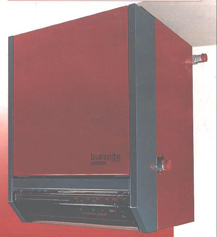
8 SECTION 2 PAGE 6 POTTERTON COMMERCIAL PRODUCTS DIVISION GENERAL This boiler is NOT SUITABLE for installation in a normally occupied area (i.e. kitchen). A LIFETIME GUARANTEE is available on this boiler please refer to our standard terms and conditions for details. Red RAL 3001 Grey (Non Standard but closest match RAL 7024) Assembled Boiler The Potterton Derwent Prestige cast iron sectional boiler is available in sixteen sizes from 66kW (5- section model) to 348kW (22-section model). Tables 3 (page 2) and 4 (page 3) give kw outputs and technical data for each model. Nat Gas LPG % 100 % 30% Gross 82.9% 82.9% They are approved for use on open vented systems (minimum head 5mm), however, they are suitable for use on sealed systems with a minimum operating pressure of 0.5 bar (0.1 bar Available on request) and a maximum operating pressure of 5 bar (73.5 p.s.i.). Refer to relevant British Standards and Codes of Practice regarding the installation of Derwent Prestige boilers on sealed systems. For sites with restricted access the boiler block, with the burner and drain cock removed, will pass through a 660mm doorway. If necessary the boiler block can be easily stripped down into individual sections. Each section weighs approximately 40kg and the principle dimensions are mm. All assembled boilers are delivered with the gas train made to the left-hand side. For conversion requirements see page 15. The Electrical connection to the gas train assembly must be connected on site by an in line plug and socket which is connected to the control panel. (as delivered). On the 20 and 22 section boilers the flow and return connections cannot be made on the same side of the boiler they must be diagonally opposite. On the 12 to 22 section boilers the return connection and gas train CANNOT be on the same side of the boiler. The boiler sections are cast iron with pips to aid heat transfer and they are joined by EPDM flat sealing washers to flow and return manifolds. The boiler sections are insulated by 50mm glass fibre insulation. The case is finished in a powder coat paint as follows: STANDARD SUPPLY Cast iron sections Flue hood Insulated, painted steel case Eco-control panel Cleaning brush Drain Cock CONTROLS The fully automatic control system, which incorporates full safety features, includes control and high limit thermostats, thermometer and burner on/off switch. All models have automatic ignition with a sequential control box and an ionisation flame failure device fitted to an interrupted low energy pilot burner. Including two volt-free remote status contacts OPTIONAL EXTRAS Additional volt-free contacts Hours run meters Sequence controls & zone controls SHIPPING PACKAGING The 5 to 16 section boilers are delivered fully assembled with boiler, burner and flue hood on a pallet plus separate cartons for gas train, control panel and casing pack. The 17 to 22 section boilers are delivered unassembled with sections, flue hood, burner, gas train, and casing pack, on one pallet. It is recommended that the Potterton Commercial Division s trained engineers should carry out erection and commissioning, as this will make valid the LIFETIME GUARANTEE. See back page of the manual for the addresses of the Service Offices.
9 POTTERTON COMMERCIAL PRODUCTS DIVISION SECTION 2 PAGE 7 INSTALLATION The boiler should be installed in a CLEAN boiler house free of dust and corrosive vapours. During insulation of system pipework and heavy building construction work around the boiler, the boiler must be switched off to avoid damage. Before starting work a risk assessment should be carried out in the boiler house and its access to determine and ensure a safe installation and working environment. Any person installing or working on the boiler must be qualified & competent, and in the case of gas fired boilers attention is drawn to the mandatory requirement of C.O.R.G.I Registration and qualified to A.C.O.P s element 16. Also they must be electrically competent and adhere to the IEE Regulations. Boiler log book supplied. Manual Handling Any person or persons moving or lifting the boiler or any part of it, should be trained in manual handling techniques and if necessary use suitable lifting equipment to reduce the risk of injury to themselves or other people. The installation should comply with the relevant British Standard Specifications, Codes of Practice and current Building Regulations, together with any special regional requirements of the local authorities, gas undertaking and insurance company. All electrical wiring must comply with I.E.E. Regulations for the Electrical Equipment of Buildings. The installation of the boiler must be in accordance with the relevant requirements of: - Health & Safety at Work Act BS : 2000: Specification for Installation of Flues. Building Regulations Electricity at Work Regulations Management of Health & Safety at Work Regulations Manual Handling Regulations Model Water By-laws BS : 2000: Specification for Installation of Ventilation for Gas Appliances. BS 6644: 1991 Installation of Gas Fired Hot Water Boilers for Inputs between 60kW and 2MW. BS 7074: 1989: Part 2 Application Selection & Installation of Expansion Vessels & Ancillary Equipment for Sealed Water Systems. BS 6880: 1988 Codes of Practice for Low Temperature Hot Water Systems. BS 779: 1989 Cast Iron Boilers for Central Heating & Indirect Hot Water Supply (Rated Output 44kW and above). CP342:2 Centralised Hot Water Supply Gas Safety (Installation & Use) Regulations 1994 IM/11 Flues for Commercial and Industrial Gas Fired Boilers and Air Heaters. IGE/UP/1 Soundness testing & Purging Procedure for Non-Domestic Installations. IGE/UP/2 Gas Installation Pipework, boosters Compressors in Industrial & Commercial Premises. BS 7671: 1992 Requirements for Electrical Installation, IEE Wiring Regulations 16 th Edition. Manufacturers notes must not be taken in any way as overriding statutory obligations. BOILER SITING & BASE The boiler should be sited in accordance with BS 6644: 1991 with respect to protecting the boiler from damage, air for combustion and ventilation, discharge of products of combustion, clearances for service and access, temperatures, noise levels, the disposal of boiler house water and the effects of flooding of the boiler house or seepage from a roof top boiler house. See section 1 for required boiler clearances for service and cleaning. A level non-combustible floor capable of supporting the weight of the boiler filled with water, see Table 3 (page 2) and 4 (page 3) together with any additional weight bearing down on the base from connections, etc, must be provided. This should be of an adequate height above the floor so as to be raised in the case of flooding, but low enough to allow ease of erection. Typically a 50mm concrete plinth with an area equal to that of the plan of the boiler is adequate in most cases Heating systems must be installed so that water cannot be returned from the heating system to the drinking water system to which it is connected to prevent the drinking water being contaminated by the heating water or chemicals used in the heating water. Steel strips should be provided (not supplied by Potterton Commercial) to support the left and right hand section feet and the back feet of the intermediate sections, see Fig 2, page 5 for details. These strips should typically be 75mm wide and 5mm thick. L.P.G boilers MUST NOT be installed in basements/below ground or in a well.
10 SECTION 3 PAGE 8 POTTERTON COMMERCIAL PRODUCTS DIVISION For further advice on installations, refer to the relevant Potterton Technical Bulletins. VENTILATION Safe, efficient and trouble free operation of conventionally flued boilers is vitally dependent on the provision of an adequate supply of fresh air to the room in which the appliance is installed. Account must also be taken of any other fuel burning appliance existing or to be fitted when designing the ventilation and combustion air systems. IMPORTANT: The use of an extractor fan in the same room as the boiler (or in an adjacent room in communication) can, in certain conditions, adversely affect the safe operation of the boiler and therefore must be avoided. Further Guidance on Ventilation for Gas Appliances is provided by B.S 6644:1991. FLUE To ensure safe and satisfactory operation the chimney system, which may be individual or common in the case of modular boiler installations, shall be capable of the complete evacuation of combustion products at all times. The effective height of the chimney terminal(s) above the boiler(s) flue outlet(s) shall ensure sufficient buoyancy to overcome the resistance of the bends, tees and runs of the flue pipe involved and shall terminate in a down draught free zone. The number of bends used should be kept to a minimum and flue runs should not be less than 45 to a horizontal should be avoided in order to comply with the recommendations made in BS 6644:1991, British Gas Publication IM/11 Flues for Commercial and Industrial Gas fired Boilers and Air Heaters. The third edition of the 1956 Clean Air Act Memorandum and the Building Regulations should be strictly observed and approval obtained where applicable. The chimney design should avoid the formation of condensate, which may be achieved by insulating the flue. The flue system must be designed to work specifically to remove the products of combustion. IMPORTANT: 90 square bends must not be used on the flue system, 2 45 bends or easy sweep pattern should be used. A minimum of 600mm straight vertical flue should be taken off the boiler flue outlet prior to any fittings. FLUE SIZE CONSIDERATIONS Nominal flue connection sizes are given in Table 3 and 4, these sizes refer to the boiler flue connection socket, detailed dimensions of the flue adaptor to BS 835 are given in table 3 and table 4. The actual size of the flue system will depend on individual site applications. Detailed below are general considerations on sizing flue systems. These notes are for guidance only and Potterton Commercial Division cannot accept responsibility for any flue system designs. Horizontal Flue Runs Horizontal flue runs only add to the flue resistance without creating any buoyancy and must be avoided. Sloping flue runs should not be less than 45 to the horizontal. Flue resistance should be kept to a minimum but flues should not be oversized as this may lead to cold start spillage. Where horizontal flue runs are unavoidable owing to building constraints advice should be sought from a flue specialist. Common Flue Systems Where multiple boilers are installed on a common flue system then the flue system should be designed to ensure the correct operation of the flue on varying load conditions. In particular that the appliance flue draught is within the operating parameter under full load and partial load conditions. For safe and reliable operation of the boiler plant it is recommended that the variance in flue draught available at each appliance under full and part load operation is designed to a minimum. (It is recommended that the services of a specialist flue system manufacturer are sought for the design of common flue systems). For initial flue design a flue size equivalent to the total free area of the boiler flue outlet should be used as a minimum. For further information regarding ventilation & flueing see Potterton Technical Bulletin No. 4, current issue or see relevant British Standard Publication BS6644:1991. THE ABOVE RECOMMENDATIONS ARE FOR GENERAL GUIDANCE ONLY. POTTERTON COMMERCIAL DIVISION CANNOT ACCEPT RESPONSIBILITY FOR FLUE SYSTEM DESIGNS BASED ON THE ABOVE RECOMMENDATIONS.
11 POTTERTON COMMERCIAL PRODUCTS DIVISION SECTION 3 PAGE 9 WATER CIRCULATION SYSTEMS The water circulation systems should be indirect and installed in accordance with the relevant parts of British Standards Codes of Practice CP342 and BS 6644: The maximum and minimum design temperature differential across the boiler should be 20 C and 10 C and the boiler should be prevented from operating with flow rates giving a temperature difference across the boiler greater than 25 C based on the full boiler output. Boilers operating under constant flow conditions can be more accurately controlled and are not subject to excessive temperature stresses. The boilers MUST NOT be fired under any circumstances with less than the minimum water flow. On systems with variable flow rates due to flow reducing devices, ie. TRVs, zone valves, etc, or where the minimum heat demand, ie. summer domestic hot water load, does not achieve the minimum boiler flow rate then consideration shall be given to incorporating a primary loop system. For further information see Potterton Publication Technical Bulletin No.1 Issue 2. It is recommended that the system is designed to give a constant flow rate. For further information on water circulation systems see Potterton publication Technical Bulletin No.1, and Technical Bulletin No.3 current issue. BOILER PROTECTION The provision of pump overrun by a time delay relay or a thermostat situated in the flow pipe close to the boiler is essential to remove residual heat from the boiler, see Fig. 32, page 35. The boiler and system should be protected by suitable frost thermostats. Never fill a hot boiler with cold water. Sudden cooling may cause the cast iron to fracture under the stress. Unions and isolating valves should be fitted to the flow and return manifolds so that the boiler can be isolated from the system if the need arises. SYSTEM WATER QUALITY High efficiency boiler systems require the water quality of the system water to be controlled by the use of inhibitors to maintain a neutral Ph and inhibit corrosion. Additionally the water system should be free of leaks to prevent raw water make up which will dilute any inhibitors, promote corrosion and form lime scale. Existing Systems On existing systems where boilers are being replaced due to failure then the cause should be investigated before installing new boilers. This can normally be achieved by cutting open a failed boiler section and examination for system debris or contamination. Lime scale is a positive indicator of continuous system water make up due to water loss. Evidence of magnetite (black sludge) in the system and the formation of gas in radiators causing air locking is a positive indicator of corrosion. Where an old system shows evidence of contamination then system cleaning should be carried out before installation of new boilers. The heating system should be chemically flushed to remove any lime scale or corrosion and a corrosion and lime scale inhibitor added. Lime scale descalers if incorrectly used could cause any remaining system debris to continue to breakdown and contaminate the new boiler causing boiler failure. Advice on system cleaning and suitable products should be sought from specialist suppliers of system cleaners such as Fernox or Sentinel. It is important to note that corrosion inhibitor can only be used in an attempt to prevent corrosion from occurring, where a system has an existing corrosion problem, inhibitors will be ineffective and the system requires cleaning. On existing systems where comprehensive descaling and desludging cannot be carried out then consideration should be given to separating the new boiler system from the existing system pipe work by the use of plate heat exchangers. New Systems New pipe work systems should be thoroughly flushed with a suitable cleaning agent to remove debris and flux residues before filling. The system water should be dosed with a suitable corrosion and lime scale inhibitor. System Water Monitoring The system water should be monitored as part of a maintenance programme to ensure the following. Raw water make up is not occurring. Corrosion and lime scale Inhibitors are still active Water Ph is below Ph 8.5 other wise on systems with aluminium content, component failures may occur. SEALED SYSTEMS General Potterton Commercial boilers are suitable for use on sealed systems designed in accordance with BS 6644: 1991 and BS 6880 Part 2. In addition, reference should be made to the Health & Safety Executive guidance note PM5 "Automatically Controlled Steam & Hot Water Boilers". Noise Level Derwent Prestige atmospheric boilers are regarded as being commercially quiet, ie < NR63 under typical operating conditions
12 SECTION 4 PAGE 10 POTTERTON COMMERCIAL PRODUCTS DIVISION BOILER ERECTION Electrical Safety A Lifetime Guarantee is available on this boiler when the Potterton Commercial Service Department carries out Erection & Commissioning and the system meets with our recommendations. Please refer to our Standard Terms and Conditions for further details. Risk Assessment Before starting work a risk assessment should be carried out in the boiler house and its access to determine and ensure a safe installation and working environment. Regardless of the type of activity being assessed, the principles of risk assessments are the same. The basic steps are: - Classify Activity Identify Hazards Identify Existing Control Measures Determine Risk Assess Acceptability of Risk Prepare a Control Plan Implement Plan Review Plan Record Results Manual Handling Any person or persons moving or lifting the boiler or any part of the boiler, should be trained in Manual Handling Techniques and if necessary use suitable lifting equipment to reduce the risk of injury to themselves and other people. Personal Protective Equipment When undertaken any work you must comply with the Personal Protective Equipment Regulations Confined Spaces A confined space as defined in the Health and Safety Confined Spaces Regulations 1997 means any place, including any chamber, tank, vat, silo, pit, trench, pipe, sewer, flue, well or other similar space in which, by virtue of its enclosed nature, there arises a reasonably foreseeable specified risk. Precautions should be taken in all areas where, by virtue of its even partially enclosed nature, pose a reasonably foreseeable specified risk. Working on appliances can be broken down to two main systems of work. 1.) Safe systems of work are adapted for all boiler maintenance & repair work undertaken on site. 2.) The work undertaken does not affect the electrical safety of the appliance. In particular the earth connected to the buildings fixed electrical installation. In the case of (1) above electrical work should only be undertaken once the boiler has been isolated from the electricity supply and confirmed electrically dead. If this is impractical then suitable precautions must be undertaken to prevent injury. In the case of (2) above checks are specified to identify any abnormality in the electricity supply to the boiler as well as to confirm that the boiler electrical connections are reinstated correctly where it is necessary to disconnect or reconnect any internal wiring within the boiler. If it is necessary to disconnect and reconnect the appliance from the site electrical installation other than means of a plug and socket then additional checks shall be undertaken by an approved engineer to check the earth loop impedance in accordance with IEE regulations. Always carry out preliminary electrical safety checks. All appliances and central heating systems must be provided with their own means of isolation for safety purposes especially during installation and maintenance. Preparation Before the installation of the boiler a check must be made to ensure that suitable facilities are available for off-loading the boiler (the 5 to 16 section boilers come with assembled heat exchanger) and conveying it to the boiler room. Each waterway section weighs approximately 40 Kg and measures 800mm x 500mm x 80mm. Ensuring all Manual Handling Techniques are followed. Particular attention must be paid to ensuring cleanliness of the boiler room and waterway sections, dust or moisture may result in imperfect adhesion of the sealants which are applied during the erection of the waterways. All tapped holes should be degreased before making connections.
13 POTTERTON COMMERCIAL PRODUCTS DIVISION SECTION 4 PAGE 11 C.O.S.H.H During the erection procedure there are a number of items which are subject to the Control Of Substances Hazardous to Health (C.O.S.H.H) Regulations, and may require specialist Personal Protective Equipment (P.P.E) beyond what is normally required. Listed below are the items subject to the C.O.S.H.H Regulations and the recommended precautions that should be taken. For a full breakdown of any substances listed below, please contact the Commercial Technical Department. carrying out the proposed work, attending site. As this will eliminate one source of on site injury taking place, if this is unable to be done notice prior to attending site should be given. V. When boilers are to be stripped and rebuilt, labour and transport should be provided for moving the sections from the delivery point to the final erection point. If this is unable to be provided notice prior to attending site should be given. 1) Refractory Ceramic Fibre Insulation Wear gloves, overalls and safety glasses, in the case of an irritation rinse the affected area with water and wash gently, in the case of eye contact, flush abundantly with water, if irritation persists seek medical advice. VI. VII. VIII. Sections/casing etc, should be kept in a clean and dry area prior to erection/assembly. Water should be available. A drain off area should be available. 2) High Temperature Glass Fibre Insulation Wear gloves, overalls and safety glasses, in the case of an irritation rinse the affected area with water and wash gently, in the case of eye contact, flush abundantly with water, if irritation persists seek medical advice. 3) Adhesive Wear gloves, overalls, in the case of an irritation rinse the affected area with water and wash gently, in the case of eye contact, flush abundantly with water, and if irritation persists seek medical advice. Inhalation continued exposure should be prevented. 4) Sealing Rope - Wear gloves, overalls, in the case of an irritation rinse the affected area with water and wash gently, in the case of eye contact, flush abundantly with water, and if irritation persists seek medical advice. IX. Power should be available. X. A site representative should be available at all times. XI. Clear instructions supplied to the persons carrying out the proposed work regarding positioning the boiler. XII. Fire evacuation procedures, facilities availability, specific Health & Safety information, etc, should be provided. Items VII to X are essential if boilers require pressure testing. Potterton Commercial Customer Erection/Assembly Check List The items listed below have been put together as a guide to what actions should be completed before the erection/assembly of a boiler takes place. I. Site access available for persons carrying out the proposed work. II. III. IV. Site Managers/Personnel aware that work will be taking place. Risk Assessments carried out on possible risks which may effect the persons carrying out the proposed work. Sections and fittings boxes were applicable should be positioned adjacent to the plinth(s) within the boiler house prior to persons


 into the tapped holes in the sections (Fig 4).")
.")
14 SECTION 4 PAGE 12 POTTERTON COMMERCIAL PRODUCTS DIVISION Heat Exchanger Assembly Models 5 section to 16 section come delivered with the heat exchanger already assembled. The control panel, gas train and casing are packed separately and clearly labelled. Fig 3 A D A Models 17 section to 22 section are delivered unassembled. The flue hood, gas train, burners, casing and control panel are delivered on one pallet. Provided below is a detailed assembly instruction procedure for erecting the boilers. It is advisable to read the instructions fully before starting assembly. Assembly of Boiler Block L R Remove the shrink wrap and metal straps securing the components to the pallet. Identify the bag of fasteners, thermostat pocket and spacers, ceramic rope, glue and Vaseline packed in the casing box. Fig 4 Fig 5 D Clean the sealing ring ports on the sections with a dry rag, DO NOT use oil or any other compound. Check that the sections are clear of swarf, sand or any other debris. C R The heat exchanger consists of three types of sections these being the left hand section (L), the middle section (M) and the right hand section (R). (Fig 3). Fig 6 Fig 7 A Fit the M10 studs (shorter thread) into the tapped holes in the sections (Fig 4). R Fix the outlet manifold (D) (it has four ½ holes (C)) to the right hand section using one of the assembly plates (A) (Figs 5 & 6). Note: Ensure that the outlet is on the side, which has been specified. Fix it to the left hand section in the same way (Fig 7). Fig 8 Fig 9 A L Add the sealing rope to the left hand side of the sections. The rope is pre-cut to two different lengths, one for the front and one for the back and should be glued with the adhesive provided and trimmed to length if necessary (Fig 8 & 9). WARNING: The adhesive gives of a flammable vapour and skin and eye contact should be avoided. If the adhesive comes into contact with: - a) SKIN then resin removing cream should be used and not a solvent to remove it. L M M
 INHALATION continued exposure should be prevented and the user should be removed to open air and if necessary medical advice sought.")
.")


 slacken the assembly plate A slightly to enable the final section to be moved up then")
15 POTTERTON COMMERCIAL PRODUCTS DIVISION SECTION 4 PAGE 13 b) EYES the eye should be irrigated with water and medical treatment sought. c) INHALATION continued exposure should be prevented and the user should be removed to open air and if necessary medical advice sought. The adhesive should be used sparingly as it is only used to keep the rope in position until the sections are clamped together. The end sections should be at right angles to the floor and siting on steel strips required under the section feet (see fig 2 page 5). The sections should be spaced so that the distance between the centres of the end sections are as Dimension B + 20mm in Fig 10, it is essential that this dimension is maintained at the top and bottom, otherwise the bottom feet of the end sections may toe in and this will make fitting the base tray difficult. The boiler should now be sitting in its final position to avoid further movement when fully assembled. Take an intermediate section and hang it on to the front manifold against the left-hand end section taking care not to snag and pull off the sealing rope. Add all of the intermediate sections until the last one is in place. While maintaining continuous pressure on the right hand section in the direction shown by the arrow (Fig 11) slacken the assembly plate A slightly to enable the final section to be moved up then retighten the clamping plate. Fig 10 G Fig 11 Fig 12 A Fig 13 B H T No. Of Sections B (mm) Fit the 3 tie bars, one at the front and two at the back. Loosen the two clamping plates, fit the base tray in position and tighten the tie rods on the boiler up to dimension B Fig 10. Check this dimension carefully and check that the sections are at right angles as shown in (fig 12). Fit the return manifold (E) (Fig 13). Centering the ¾ hole (drain) positions the manifold accurately with respect to its clamping plate (F). Fit the clamping plate using just 2 nuts at each end. Fitting the Seals Pull the return manifold about 15 to 20mm away from the cast iron heat exchanger using a lever (chisel or screwdriver). Insert the seals at an angle, locating the bottom in the recess and letting the top rest against the manifold (Fig 13 & 15). F E Fig 14 Fig 15 F E

16 SECTION 4 PAGE 14 POTTERTON COMMERCIAL PRODUCTS DIVISION NOTE: Do not use glue or mineral grease that might attack the EPDM seals. Only the Vaseline supplied should be used in contact with the seal. Fit the washers and nuts and tighten until the seals are in contact, but without clamping the manifold. Ensure that the tie rods (T) are taking the strain and then remove the assembly plates A from the outlet manifold and fit the clamping plate (G Fig 10). Fig 16 A: Ø7mm silicone rubber bead B: 20x3 ceramic felt Fit the seals in the same way for the outlet manifold (Fig 14 & 15). Once the heat exchanger has been assembled, but not clamped, the sections can be shaken down by tapping repeatedly on the sides. A Check Once Again: a) That length B at the tie rods is correct. b) That the manifolds are correctly positioned (holes centred in the clamping plates) c) That the return manifold is at right angles to the sections. Tighten all the nuts on the manifolds evenly. Fit the temperature monitoring sleeve in the ½ hole (H) in the section (8) nearest the outlet. Fit the drain tap to ¾ hole in the return manifold. Combustion Chamber Base Plate Put an insulating sealing strip on the bottom right and left edges of the combustion chamber (Fig 16) and put an insulation strip on top at the back edge. Insert the base plate with the front fold downwards, being careful not to damage the seals and ensure a good seal. INSTALLING MULTIPLE UNASSEMBLED BOILERS When two boilers are being built side by side with the minimum practical clearance between them and with one flow connection to the left and the other to the right, the end sections should be positioned on the base as shown in Fig 17. Fig 17 B 150mm (Minimum) Hydraulic Test of Boiler This is to be carried out on boilers assembled on site or where water manifolds have been disturbed. Fit a hydraulic test pump to the return manifold and fit a valve to vent air from the flow connection. Fill the boiler with cold water and, in accordance with BS 779, 1976 pressurise up to 1.5 times the system design pressure, ie. 7.5 bar maximum, and observe for 30 minutes.


17 SECTION 4 PAGE 15 POTTERTON COMMERCIAL PRODUCTS DIVISION FITTING OF BURNER ASSEMBLY 17 to 22 SECTION. Stage 1: Fold the pieces of insulation as Figure No 1 and then fit the pieces of insulation firmly in between the sections legs at the rear of the boiler. See figure No Stage 2: Clean the base tray-mounting seat and fix the sealing strip with the adhesive provided. See figures 3 / 4 / Stage 3: Insert the base tray inside the combustion chamber See figures 6 / 7. slots 6 7 Stage 4: When the base tray is in position fit the sealing tape on the front edge of the base tray using the adhesive and sealing tape provided See figures 8/ 9 /10.


18 SECTION 4 PAGE 16 POTTERTON COMMERCIAL PRODUCTS DIVISION Stage 5: The complete burner assembly can now be fitted to the boiler by locating the burner assembly on to the studs on the end sections See figures 11 / 12 Slots For studs studs : Connect the pilot tube of 4mm diameter to the 6mm pilot tube elbow and on to the gas valve by the BANJO Stage Connection See figures 13 /14 6mm Connection Banjo Connection Boiler Maintenance It is essential that when the maintenance of the boiler takes place that the pieces of insulation are inspected and if they are showing any signs of deterioration they should be replaced. Please refer to Boiler Maintenance on section 4 Page 29.

19 POTTERTON COMMERCIAL PRODUCTS DIVISION SECTION 4 PAGE 17 Fitting of Flue Hood and Burners Fit the rear panel of the casing before the flue hood. The flue hood is fitted onto the top of the boiler block and a seal must be made using the ceramic felt provided, between the sections and the flue hood. Take the roll of ceramic felt packed with the boiler and cut a strip and glue it across the front end of the sections. Next cut two pieces of sealing strip to form the side seal (I) on top of each end section see Fig 18. Handing Flow & Return On the 20 and 22 section boilers the flow and return connections must not be made on the same side of the boiler they MUST be diagonally opposite. On the 12 to 22 section boilers the return and the Gas Train cannot be on the same side. Fig 18 Finally add the rear sealing strip. This sealing strip does not sit on the top of the end sections but underneath the lip at the back of each section. Fix the hood using the clamping plates (K) (Fig 18). Ensure that there is a good seal made between the back of the heat exchanger block and the flue hood. See Page 21 for handing the gas manifold. V J K W I Burner Manifold The burner manifold (T) can be fitted with the gas inlet on the right or left. It is fixed to the front panel (U) by four nuts and washer spacers supplied (Fig 18). Note: on the 12 to 22 section boiler the gas train and the return cannot be on the same side of the boiler. W Combustion Chamber Front Plate U Bond the silicone rubber foam strips to the right and left hand sections of the heat exchanger delivered unassembled and bolt to the front plate (U) to these sections (Fig 16). Use the nuts and washers supplied. Put an insulating sealing strip on the front fold of the base plate. The base plate is not screwed to the front plate (U) of the burner. Gas Train X Y Z T T Z The gas train (X) is delivered assembled and prewired to be fitted to the right or left. It is connected to the connector on the gas burner manifold by a union (Y) (Fig 18). Remove the cap from the appropriate connector Y and tighten the free part of the union, using a flat washer to seal the joint. Fit the pilot light assembly to the appropriate side (Z or Z ) this MUST be fitted on the same side of the burner plate as the gas train. Fit the pilot light supply tube. For connection see Gas Supply. Fig 19 V V

. 4. Repeat for the left hand rear side panel (item 4). 5.")
20 SECTION 4 PAGE 18 POTTERTON COMMERCIAL PRODUCTS DIVISION Assembly of Casing (5 to 8 Section) (The following description should be read in conjunction with Figs. 20 and 21) 1. For the 5 to 8 section boilers, the insulation is wrapped around the boiler. It is stapled at the back and held by a bracket on the right and left. 2. The rear panel (item 1) and the internal front panel (item 2) are delivered mounted directly on the boiler. These will need to be loosened slightly to allow alignment of the side and top panels. 3. Fix the right hand rear panel (item 3 by fixing it onto the front and rear panels (items 1 & 2). 4. Repeat for the left hand rear side panel (item 4). 5. Fit the control panel locating bracket (item 11) onto the support panel (item 5) and fix to the front edges of the right and left rear side panels (item 3 & 4). 6. Attach the control panel (item 6) directly to the mounting plate using the studs and the two clamping screws on the control panel mounting plate (item 5). 7. Secure the earth wire from the heat exchanger to the bottom right hand side of the control panel and proceed with the electrical wiring (see boiler wiring diagram on page 33 & 34). 8. Put the insulation on the top of the fluehood, run the 230V cable for the control panel in the right hand channel and the wiring for the sensors through the left hand channel and fit the top (item 9) on the studs. There is a notch at the back of the side panels to help position the top. 9. Tighten the nuts on the back plate (item 1) and the internal front plate (item 2). 10. Fit the front right hand side panel (item 7) to the side panel (item 3) and the control panel (item 6). 11. Fit the front left hand side panel (item 8) to side (item 4) and the control panel (item 6). 12. Screw the door chains to the brackets. 13. Fit the brackets for the quarter turn locks to the front left and right hand panels using nuts. 14. Fit the quarter turn locks to the door (make sure that the clips are fitted correctly). 15. Fit the door (item 10), attach the chains, connect the earth wire from the door earth wire from the door earth terminal (bottom right of the door) to the earth terminal on the base of the front right hand panel and close it using the quarter turn locks. Fig 20 General Arrangement of Casing (5 to 8 Section) Door earth wire terminal Mounting holes for 5 section boiler 1 - Rear Panel 2 - Front Panel 3 - Right Hand Rear Side Panel 7 - Right Hand Front Side Panel Insulation Bracket 2 Mounting holes for 5 section boiler
21 POTTERTON COMMERCIAL PRODUCTS DIVISION SECTION 4 PAGE 19 Fig 21 General Arrangement of Casing (5 to 8 Section) Quick Release Screw Control Panel Earth Wire Slot for Clip Spring Clip Spring Control Panel Earth Wire Terminal Door Earth Wire Terminal 4 - Left Hand Rear Side Panel 5 - Control Panel Support Panel 6 - Control Panel Housing 8 - Left Hand Front Side Panel 9 - Top Panel 10 - Boiler Door 11 - Control Panel Support Brkt
22 SECTION 4 PAGE 20 POTTERTON COMMERCIAL PRODUCTS DIVISION ASSEMBLY OF CASING [9 to 22 section] The following description should be read in conjunction with Fig.22 & On the 9 to 22 section boilers the insulation is fixed by the front and rear panels. The sides are insulated with insulation glued onto the side panels. 2. Position the rear insulation between the draught diverter and the heat exchanger and secure it in place with the right hand rear panel (item 1) mounted on the heat exchanger. Do not tighten the screws fully until side panels have been fitted. 3. Repeat for the left hand rear panel (item 2). 4. Fit the draught diverter (if delivered separately). 5. Position the front insulation and hold in place by screwing the right hand boiler front panel (item 6) to the heat exchanger. Do not fully tighten the screws. 6. Attach the connector strips (items 3 and 4) to the right hand front panel attached to the boiler. 7. Fit the left hand boiler front panel (item 5) to the connector strips and screw to the heat exchanger. 8. Fit the right hand rear side panel (item 3) to the front and rear panels already attached to the boiler. 9. Repeat for the left hand rear side panel (item 8). 10. Fit the control support panel (item 9) to the front edges of the right and left rear side panels previously fitted. 11. Hang the control panel (item 10) towards the right hand side of the support panel using the locating pin and two fixing screws provided.(it will not be possible to attach the left hand side). 12. Fit the extension panel (item 11) onto the left hand side of the support panel using the locating pins and fixing screws provided. Secure the extension panel to the control panel with one screw through the inside of the control panel. 13. Fix the earth wire from the heat exchanger to the bottom right hand side of the control panel and proceed with electrical wiring (see boiler wiring diagram on page 33 and 34). 14. Place the top insulation panel on the draught diverter before fitting the top panel (item 16). 15.Tighten the screws on the front and rear panels. 16. Fit the right hand front side panel (item 7) onto the rear sided panel (item 3) and the control panel. 17.Fit the left hand front side panel (item 13) onto the rear side panel (item 8) and the control panel. 18. Mount the quick release fixing brackets (with chain already attached) onto the front side panels (items 7 and 13). 19. Assemble the door quick release door fixings as in step 13 under 5 to 8 Section Casing Fitting). 20. Position the door near the front side panels and attach the earth wire from the bottom of the front side panel to the bottom door fold using the push clip provided. Hang the door on the bottom hinge bolts and attach the right and left hand restraining chains in the holes in the door top fold. 21. Close the door and secure the quick release screw using a screwdriver. Fig General Arrangement of Casing (9 to 22 Section) 1 - Right Hand Rear Panel 2 - Left Hand Rear Panel 3 - Right Hand Rear Side Panel 4 - Bottom Front Insulation Fixing Brkt 5 - Left hand Boiler Front Plate 6 - Right Hand Boiler Front Plate 7 - Right Hand Front Side Panel 14 - Ignition Transformer Unit Back Insulation Front Insulation
Derwent Prestige Plus Installation, operation & maintenance manual
 To be kept by the user March 2010 Derwent Prestige Plus Installation, operation & maintenance manual Working towards a cleaner future heating specialists INDEX Section 1 Page Page Fig. 1 - General Data
INDEX. Page. Page. Section 1
 MAY 2007 INDEX Section Page Page Fig. - General Data & Dimensions Table - Boiler Dimensions Table 2 - Combustion Chamber Data Table 3 - Technical Data 2 - Explanatory Notes 3 - Clearances 4 Fig. 2 - Boiler
INDEX. Page SECTION 2. General 5 Standard Supply 5 Controls 5 Optional Extras 5 Shipping Packaging 5 Installation 5 Boiler Siting and Base 6 SECTION 6
 POTTERTON RAPIDO APRIL 2005 INDEX SECTION 1 Page Page Fig. 1 General Data & Dimensions 1 Table 1 Boiler Dimensions 1 Table 2 Combustion Chamber Data 1 Table 3 Technical Data 2 General information 3 Fig.2
GAS FIRED ATMOSPHERIC ELECTRONIC VERSION kw
 GAS FIRED ATMOSPHERIC ELECTRONIC VERSION 51-102 kw GENERAL DESCRIPTION 900 D a3 1000 762 672 E 222 The PEGASUS F2 range of atmospheric natural gas-fired boilers are constructed of cast iron finned sections
ATMOSPHERIC GAS BOILER INSTALLATION, OPERATING AND MAINTENANCE MANUAL
 STREBEL GENEVA CE ATMOSPHERIC GAS BOILER INSTALLATION, OPERATING AND MAINTENANCE MANUAL INDEX TABLE 1 TECHNICAL DATA SECTION 1 SECTION 2 SECTION 3 SECTION 4 SECTION 5 SECTION 6 SECTION 7 SECTION 8 SECTION
Clyde CK40. Cast Iron Boiler. Engineering Data Sheet 663/8 May Natural gas Class D oil Dual Fuel. 350 kw to 500 kw
 atural gas Class D oil Dual Fuel 350 kw to 500 kw Clyde CK40 Cast Iron Boiler Contents Page General information Dimensions 3 Technical data 3 Installation requirements 4 & 5 Boiler control panel 6 Wiring
CAST IRON PREMIX HIGH EFFICIENCY GAS FIRED BOILER kw BRILEY DESIGN MANUAL
 BRILEY CAST IRON PREMIX HIGH EFFICIENCY GAS FIRED BOILER 60 140 kw 0604.2 Beeston Briley cast-iron premix gas-fired boiler 60-140kW Contents 1 Boiler specifications Page 3 2 Appliance general dimensions
Heat Exchanger Block Replacement Instructions
 Series 1-4 Gas-fired water boiler Heat Exchanger Block Replacement Instructions Ultra-80 S1-4 Heat Exchanger Block Replacement Kit, Part No. 383-500-773 Ultra-105 S1-4 Heat Exchanger Block Replacement
Synergy Grill User & Engineer Installation & Conversion Guide
 Synergy Grill 1300 User & Engineer Installation & Conversion Guide 1 Index: Description Page Number/Section Important Information 3 Installation 4-6 / Section 1 Commissioning 6 / Section 2 Converting Gas
Osprey 2 CFL
 Osprey 2 CFL 125-150 - 180-220 Gas Fired Floor Standing Boiler Installation and Servicing Instructions Please leave these instructions with the user Natural Gas Potterton Osprey 2 CFL 125 G.C.N o 41 590
U tube models PTU 09, 12, 15, 25, 30, 35, 40, 45. single linear tube models PTS 09, 12, 15, 25, 30, 35, 40, 45
 U tube models PTU 09, 2, 5, 25, 30, 35, 40, 45 & single linear tube models PTS 09, 2, 5, 25, 30, 35, 40, 45 installation, servicing & operating instructions INSTALLATION, SERVICING AND OPERATING INSTRUCTIONS
Remeha. Fuel oil/gas boilers P 520. Installation and Service Manual A
 Remeha Fuel oil/gas boilers EN Installation and Service Manual 300016859-001-A 63115 Declaration of conformity The appliance complies with the standard model described in declaration of compliance. It
Built-in Gas Hob CZ55554 CZ55571
 Built-in Gas Hob CZ55554 CZ55571 INSTALLATION AND OPERATING INSTRUCTIONS The product may differ from the one illustrated but the installation and operation procedure remains the same The product may differ
R e m e h a P Technical Information. Remeha P 300. Pressurized boiler. Heat output: kw
 Technical Information Remeha P 300 R e m e h a P 3 0 0 Pressurized boiler Heat output: 278-709 kw Remeha P 300 CONTENTS Preface 3 1 Description of the unit 3 1.1 General 3 1.2 Burners 3 2 Construction
Technical information. Remeha P 500. Pressurized boiler. Heat output: kw
 Technical information Remeha P 500 R e m e h a P 5 0 0 Pressurized boiler Heat output: 635-1900 kw Remeha P 500 TABLE OF CONTENT Preface 3 1 Description of the unit 3 1.1 General 3 1.2 Burners 3 2 Construction
Cast Iron Boilers. G Series ( kW)
") Cast Iron Boilers G Series (320-1017kW) Mikrotherm G Series Cast Iron Boilers The Mikrotherm G Series of cast iron sectional boilers offer all the advantages of cast iron durability and longevity coupled
Cast Iron Boilers G Series (320-1017kW) Mikrotherm G Series Cast Iron Boilers The Mikrotherm G Series of cast iron sectional boilers offer all the advantages of cast iron durability and longevity coupled
TEMPRA. Wall Mounted Fan Flue System boiler. Wall mounted fanned flue boiler INSTALLATION AND USE INSTRUCTIONS. Appr. nr. B A - CE 0063 AQ 2150
 Wall Mounted Fan Flue System boiler Appr. nr. B 94.04 A - CE 0063 AQ 2150 Phone numbers: Installer Service Engineer Serial N Wall mounted fanned flue boiler INSTALLATION AND USE INSTRUCTIONS Please read
To be kept by the user heating specialists
 To be kept by the user Jan 2010 Arizona 99 930kW Installation, operation & maintenance manual Working towards a cleaner future heating specialists WARNING When the boiler is operated with a pressure jet
TopGas Cascade Condensing Gas Boilers Technical Information and Assembly Manual Output range 60 to 720 kw /17 Subject to modification
 TopGas Cascade Condensing Gas Boilers Technical Information and Assembly Manual Output range 60 to 720 kw Subject to modification Contents 1. Important Information 4 1.1. Documentation 4 1.2. Guarantee
ferroli Boiler Replacement Maxima 35C- Modena HE
 ferroli Boiler Replacement Maxima 35C- Modena HE Introduction Although the new Ferroli Modena 32C HE high efficiency condensing combination boiler has an output slightly less than that of the Ferroli Maxima
Mikrofill Ethos Condensing combination boiler
 Mikrofill Ethos Condensing combination boiler User Instructions 24cc CE Mark Mikrofill gas appliances comply with the requirements contained in CE Mark documents contained with European directives applicable
Unvented Calorifier Range. Operating and Maintenance Manual. For Models & 500
 Unvented Calorifier Range. Operating and Maintenance Manual. For Models 125 300 & 500 Telephone 08456 448802 Fax 08456 448803 Emial info@mhgheating.co.uk Web www.mhgheating.co.uk TABLE OF CONTENTS. Section
Aluminium range of condensing boilers. Works every time. Designed to meet carbon reduction targets. Lifetime service and support
 Aluminium range of condensing boilers Outputs from 30kW to 600kW Designed to meet carbon reduction targets Lifetime service and support Works every time. www.pottertoncommercial.co.uk Aluminium range of
Clyde Alkon 90. Floor standing condensing boilers. Natural Gas. 90 kw. LP Gas. 90 kw
 90 kw Clyde Alkon 90 LP Gas Floor standing condensing boilers Natural Gas 90 kw Contents General information Dimensions and Data Installation requirements Boiler wiring diagram Hydraulic systems Page Fully
SIME FORMAT WALL HUNG BOILERS MODEL 34i AND MODEL 34e. cod A
 cod. 6272262A GENERAL DATA Heating Data Heat Output Input (Adjustable) (Adjustable) Format 34i 11.2 34KW 45 145MJ/hr Format 34e 11.2 34KW 45 145MJ/hr General Specifications FORMAT 34i 34e Main burner injectors
INSTALLATION INSTRUCTIONS
 INSTALLATION INSTRUCTIONS Gas-on-glass cooktop CG302D, CG451D, CG603D, CG604D, CG752D, CG903D & CG905D models GB IE IN 590657A 02.14 1 SAFETY AND WARNINGS 3 WARNING! Electrical shock hazard Before carrying
INSTALLATION INSTRUCTIONS COMPACT GAS STOVE MODEL NUMBER 550
 INSTALLATION INSTRUCTIONS COMPACT GAS STOVE MODEL NUMBER 550 Before installation ensure that the local distribution conditions (identification of the type of gas and pressure) and the adjustment of the
Alpha CD13R,18R and 24R
 Installation and Servicing Instructions Alpha CD3R,8R and 24R Wall Mounted, Fan Assisted, Room Sealed, Gas Fired, High Efficiency Condensing Regular Boiler Range For Technical help or for Service call...
GAS-ON-GLASS COOKTOP
 GAS-ON-GLASS COOKTOP CG301D, CG302D, CG451D, CG603D, CG604D, CG752D, CG903D & CG905D models INSTALLATION GUIDE GB IE IN PH 590657D 08.17 1 SAFETY AND WARNINGS! WARNING! Electrical shock hazard Disconnect
THE SEVERN. Installation Instructions for Freestanding Severn Stove with Boiler PERFORMANCE RATING
 THE SEVERN Installation Instructions for Freestanding Severn Stove with Boiler Consumer Protection Act 1987 As manufacturers and suppliers of cooking and heating products, in compliance with Section 10
INSTALLATION AND SERVICING
 AND SERVICING HARRIER GTS 5-9 When replacing any part on this appliance, use only spare parts that you can be assured conform to the safety and performance specification that we require. Do not use reconditioned
This appliance must be installed and serviced by a competent person as stipulated by the Gas Safety (Installation & Use) Regulations.
 Regulations.") G3512 and G3532 DOMINATORPLUS Grills INSTALLATION and SERVICING INSTRUCTIONS This appliance must be installed and serviced by a competent person as stipulated by the Gas Safety (Installation & Use) Regulations.
G3512 and G3532 DOMINATORPLUS Grills INSTALLATION and SERVICING INSTRUCTIONS This appliance must be installed and serviced by a competent person as stipulated by the Gas Safety (Installation & Use) Regulations.
Condensing Boilers. Floor Mounted - Evomod, Imax Xtra & Imax Plus III. Commercial Heating Solutions.
 Condensing Boilers Floor Mounted - Evomod, Imax Xtra & Imax Plus III www.idealcommercialheating.com Commercial Heating Solutions Introduction - Ideal Commercial & Industrial Pioneering heating solutions
INSTALLATION AND SERVICING INSTRUCTIONS
 9/4CBi, 4/9CBi, 9/4CBi WALL MOUNTED BOILERS FOR CENTRAL HEATING AND INDIRECT SUPPLY OF DOMESTIC HOT WATER INSTALLATION AND SERVICING INSTRUCTIONS Worcester supports the Benchmark code of practice This
Installation and maintenance instructions
 6304 4995 0/004 GB For installer Installation and maintenance instructions Flue gas heat exchanger WT50/60 Please read thoroughly prior to installation and maintenance. Summary About this manual This equipment
superrange Super Series 4, Super Plus High efficiency modular boilers kW Commercial & Industrial Boilers
 superrange Super Series 4, Super Plus High efficiency modular boilers 50-600kW Commercial & Industrial Boilers the super range Contents Introduction 3 The Super range 4-5 Product specification 6-7 System
Stainless steel range of condensing boilers. Designed to meet carbon reduction targets. Lifetime service and support. Outputs from 50kW to 660kW
 Stainless steel range of condensing boilers Outputs from 50kW to 660kW Designed to meet carbon reduction targets Lifetime service and support Totally dependable. page 1 www.pottertoncommercial.co.uk Contents
Superior. A Compact Floor Standing Gas Fired, High Efficiency Condensing Hot Water Boiler. Outputs 120, 160, 200, 240, 280 kw
 Superior A Compact Floor Standing Gas Fired, High Efficiency Condensing Hot Water Boiler Outputs 120, 160, 200, 240, 280 kw 1 The Superior is a, pre-assembled floor standing, gas fired high efficiency
pressurejetrange Buccaneer GTE, Falcon GTS, Harrier GTS, Viceroy GTS, Viscount GTS, Vanguard L Pressure jet boilers kW
 pressurejetrange Buccaneer GTE, Falcon GTS, Harrier GTS, Viceroy GTS, Viscount GTS, Vanguard L Pressure jet boilers 21-3500kW Commercial & Industrial Boilers the pressure jet range Contents Introduction
JANUS 3 CIRCULATOR WATER HEATER INSTALLATION, COMMISSIONING & SERVICING INSTRUCTIONS G.C. No
 JANUS 3 CIRCULATOR WATER HEATER INSTALLATION, COMMISSIONING & SERVICING INSTRUCTIONS G.C. No 53 416 06 Publication No. ZZ 180/17 May 2000 These appliances are tested and certified by B G Technology for
Assessment Schedule - TS.6
 The Assessor shall determine the business s commitment and support to good and safe working practices; also that it has a positive culture in all aspects of its work. In particular, the assessor shall
MULTIPOINT BF Gas Fired Balanced Flue Water Heater
 Please leave these instructions with the user MULTIPOINT BF Gas Fired Balanced Flue Water Heater User Operating, Installation and Servicing Instructions 6 720 607 090 (03.12) JS Natural Gas Main Multipoint
BAXI BOSTON ALL MODELS FLOOR STANDING OPEN FLUE (OF) CENTRAL HEATING BOILERS INSTALLATION AND SERVICING INSTRUCTIONS. GAS TYPE G20 (Natural Gas)
 CENTRAL HEATING BOILERS INSTALLATION AND SERVICING INSTRUCTIONS. GAS TYPE G20 (Natural Gas)") BAXI BOSTON ALL MODELS FLOOR STANDING OPEN FLUE (OF) CENTRAL HEATING BOILERS INSTALLATION AND SERVICING INSTRUCTIONS GAS TYPE G20 (Natural Gas) BAXI BOSTON 80 OF G.C. No 41 077 65 BAXI BOSTON 70 OF G.C.
BAXI BOSTON ALL MODELS FLOOR STANDING OPEN FLUE (OF) CENTRAL HEATING BOILERS INSTALLATION AND SERVICING INSTRUCTIONS GAS TYPE G20 (Natural Gas) BAXI BOSTON 80 OF G.C. No 41 077 65 BAXI BOSTON 70 OF G.C.
Installation & Servicing Instructions
 Installation & Servicing Instructions Baxi System 35/80 IE & 60/100 IE Gas Fired Wall Mounted System Boiler Please keep these instructions safe. Should you move house, please hand them over to the next
Baxi System 100 HE Plus. User s Operating Instructions. Wall Mounted Powered Flue Condensing Gas Fired Central Heating Boiler
 User s Operating Instructions Baxi System 100 HE Plus Wall Mounted Powered Flue Condensing Gas Fired Central Heating Boiler Please keep these instructions safe. Should you move house, please hand them
Bosch Group. 15SBi / 24SBi. WALL MOUNTED BOILERS FOR CENTRAL HEATING and Indirect supply of domestic hot water
 Bosch Group 15SBi / 24SBi WALL MOUNTED BOILERS FOR CENTRAL HEATING and Indirect supply of domestic hot water INSTALLATION AND SERVICING INSTRUCTIONS 24SBi This appliance is for use with Natural Gas or
INSTALLATION AND OPERATING INSTRUCTIONS GN2. HIGH EFFICIENCY CAST IRON BOILER FOR LIQUID and/or GAS FUELS
 INSTALLATION AND OPERATING INSTRUCTIONS HIGH EFFICIENCY CAST IRON BOILER FOR LIQUID and/or GAS FUELS INDEX 1. Technical information... page 3 2. Dimensional and technical characteristics... page 3 3. Packing
Sirius FS. Working towards a cleaner future
 Sirius FS Floor Standing Stainless Steel Condensing Boilers Single Boiler Applications: 50 to 160kW Modular Boiler Applications: up to 640kW Working towards a cleaner future heating specialists 1. Product
GENERAL. Note. To obtain gas consumption in l/s, divide gross heat input in (kw) by a calorific value of 37.8 (MJ/m 3 ).
 by a calorific value of 37.8 (MJ/m 3 ).") GENERAL Table 1- Performance Data Boiler CXA 40/H CXA 50/H CXA 60/H CXA 70/H CXA 80/H CXA 90/H CXA 100/H CXA 110/H CXA 120/H Number of Sections 3 4 4 5 5 6 6 7 7 Boiler Input Gross kw 48.3 60.3 72.4 84.5
GENERAL Table 1- Performance Data Boiler CXA 40/H CXA 50/H CXA 60/H CXA 70/H CXA 80/H CXA 90/H CXA 100/H CXA 110/H CXA 120/H Number of Sections 3 4 4 5 5 6 6 7 7 Boiler Input Gross kw 48.3 60.3 72.4 84.5
ProCon Streamline Gas Condensing Boiler. Installation and Operating Manual.
 1 MHG Heating Ltd ProCon Streamline Gas Condensing Boiler. Installation and Operating Manual. Unit 4 Epsom Downs Metro Centre, Waterfield, Tadworth, Surrey, KT20 5LR Telephone 08456 448802 Fax 08456 448803
range W, Plus Condensing boilers kW Commercial & Industrial Boilers
 range W, Plus Condensing boilers 45-280kW Commercial & Industrial Boilers the range Contents Introduction 3 The Range 4-5 Product specification 6-9 Option kits 10-11 Flueing 12-15 System requirements 16-19
Baxi Boston 2 OF Floor Standing Open Flue Gas Fired Central Heating Boilers Natural Gas Comp N Iss 8-4/00
 Baxi Boston 2 OF Floor Standing Open Flue Gas Fired Central Heating Boilers Natural Gas Comp N 235305 - Iss 8-4/00 Please leave these Instructions with the User. Installation and Servicing Instructions
Greenstar System Filter
 Installation and Servicing Instructions Greenstar System Filter For sealed and open vented central heating systems with 22 or 28mm central heating pipes 672087500-00.Wo UK/IE 6 720 87 500 (205/07) Contents
TC MODULE (FFD) (with Gas Hob)
 (with Gas Hob)") TC MODULE (FFD) (with Gas Hob) Installation Instructions REMEMBER: when replacing a part on this appliance, use only spare parts that you can be assured conform to the safety and performance specification
TC MODULE (FFD) (with Gas Hob) Installation Instructions REMEMBER: when replacing a part on this appliance, use only spare parts that you can be assured conform to the safety and performance specification
OPTIMA RADIANT TUBE HEATING SYSTEMS. Operation, maintenance and servicing manual
 OPTIM RDINT TUBE HETING SYSTEMS Operation, maintenance and servicing manual CONTENTS GENERL INSTRUCTIONS Section Title Page 1. Preparing the Installation 4 2. Checking the Installation rea 5 3. Flue Connection
Pressure Jet Boilers. Pressure Jet Range. Commercial Heating Solutions.
 Boilers Range www.idealcommercialheating.com Introduction - Ideal Commercial & Industrial Contents Pioneering heating solutions since 1905 Here at Ideal, we understand that you want a reliable, long term
Hamworthy Fleet Horizontal Floor Standing. Condensing Boilers Natural Gas Outputs 40kW to 350kW 5 YEAR HEAT EXCHANGER WARRANTY
 Hamworthy Fleet Horizontal Floor Standing Condensing Boilers Natural Gas Outputs 40kW to 350kW 5 YEAR HEAT EXCHANGER WARRANTY Fleet H Floor Standing Horizontal Boilers The Fleet range of commercial boilers
These Appliances must be installed and serviced by a competent person as stipulated by the Gas Safety (Installation & Use) Regulations.
 Regulations.") G350/11 and 12 FREESTANDING FRYERS INSTALLATION and SERVICING INSTRUCTIONS These Appliances must be installed and serviced by a competent person as stipulated by the Gas Safety (Installation & Use) Regulations.
G350/11 and 12 FREESTANDING FRYERS INSTALLATION and SERVICING INSTRUCTIONS These Appliances must be installed and serviced by a competent person as stipulated by the Gas Safety (Installation & Use) Regulations.
LGB Gas fired boiler
 LGB Gas fired boiler Control Supplement LGB-5 Series 2 Propane gas CSD-1 Control System Part Number 550-110-682/0304 Please read this page first Hazard definitions To the installer... The following terms
DOMINATORPLUS ELECTRIC RANGE APPLIANCES INSTALLATION and SERVICING INSTRUCTIONS
 DOMINATORPLUS ELECTRIC RANGE APPLIANCES INSTALLATION and SERVICING INSTRUCTIONS IMPORTANT The installer must ensure that the installation of the appliance is in conformity with these instructions and National
Bosch Group. 24CDi OF WALL MOUNTED COMBINATION BOILER FOR CENTRAL HEATING AND MAINS FED DOMESTIC HOT WATER INSTALLATION AND SERVICING INSTRUCTIONS
 Bosch Group 24CDi OF WALL MOUNTED COMBINATION BOILER FOR CENTRAL HEATING AND MAINS FED DOMESTIC HOT WATER INSTALLATION AND SERVICING INSTRUCTIONS GC NUMBER 47 311 32 (N.G) GC NUMBER 47 311 33 (L.P.G.)
THE MUCH WENLOCK. Installation Instructions for Freestanding Much Wenlock Stove with Boiler
 THE MUCH WENLOCK Installation Instructions for Freestanding Much Wenlock Stove with Boiler Consumer Protection Act 1987 As manufacturers and suppliers of cooking and heating products, in compliance with
Statesman 45/50L, 50/70L, 70/90L, 90/110L, Utility 50/70L, 70/90L, 90/110L, 110/130L, 130/150L
 Users Instructions Statesman 45/50L, 50/70L, 70/90L, 90/110L, Utility 50/70L, 70/90L, 90/110L, 110/130L, 130/150L About the Boiler About Safety This is a Floor Standing, Horizontally Fired, Automatic Pressure
Installation Instructions
 Installation Instructions KFN 9855 ide en - CA Installation, repair and maintenance work should be performed by a Miele authorized service technician in accordance with national and local safety regulations
Performa System 12e, 18e, 24e & 28e
 Performa System 12e, 18e, 24e & 28e Gas Fired Wall Mounted System Boilers Installation and Servicing Instructions Please leave these instructions with the user Natural Gas Potterton Performa System 12e
Description Model Weil-McLain part number. Vent Termination Kit for 3" Stainless Steel All
 Replacement parts Figure 96 Miscellaneous parts Description Model Weil-McLain part number Vent Termination Kit for 3" PVC All 383-500-397 Vent Termination Kit for 3" Stainless Steel All 382-200-430 Vent
2 Concord CX - Installation
 CAUTION. To avoid the possibility of injury during the installation, servicing or cleaning of this appliance care should be taken when handling edges of sheet steel components. 2 Concord CX - Installation
PVE SERIES POWER VENTER SYSTEM MANUAL
 PVE SERIES POWER VENTER SYSTEM MANUAL Contents Page I. Typical Venting System Components 2 II. System Operation 3 III. Power Venter Sizing 3,4 IV. Installation Safety Instructions 5,6 V. Installation of
KEY TO COMPONENTS. 1. Heat exchanger 2. Pilot gas pipe 3. Gas injector nozzle 4. Measuring point
 Bosch Thermotechnik WR 325 BF Gas Fired Multipoint Water Heater INSTALLATION AND SERVICING INSTRUCTIONS GC NUMBER 52 311 01 For your safety if you smell gas: 3. Do not operate any electrical switches 1.
kw Btu/h Metres Feet l/min. Gal/min C C
 80ic RSF WALL MOUNTED COMBINATION BOILER FOR CENTRAL HEATING AND MAINS FED DOMESTIC HOT WATER INSTALLATION AND SERVICING INSTRUCTIONS 6 720 605 553 PT 2000 11 Cat: II 2H3+ GC NUMBER NG: 47 311 43 LPG:
COMMERCIAL GAS AND ELECTRIC STACKED WASHER/ DRYER INSTALLATION INSTRUCTIONS
 COMMERCIAL GAS AND ELECTRIC STACKED WASHER/ DRYER INSTALLATION INSTRUCTIONS MODELS MLG19PD, MLE19PD The installation, including a proper exhaust system, is the responsibility of the owner. LEAVE THESE
BENSON LINEAR RADIANT TUBE
 BENSON LINEAR RADIANT TUBE Natural or Propane (Gas fired) I N S T A L L A T I O N C O M M I S S I O N I N G S E R V I C I N G U S E R I N S T R U C T I O N S September 2001 CONTENTS Page Compliance Notices
Ultramax R600. High output, floor standing gas fired condensing boilers with outputs from 150kW to 571kW
 Ultramax R600 High output, floor standing gas fired condensing boilers with outputs from 150kW to 571kW Delivering excellence with every feature The Ultramax R600 series of boilers is packed with features
IDEAL. Concord CXA INSTALLATION & SERVICING MANUAL. Installers guide to commercial central heating boilers
 THE IDEAL INSTALLATION & SERVICING MANUAL Concord CXA 40-120 Installers guide to commercial central heating boilers CAUTION. To avoid the possibility of injury during the installation, servicing or cleaning
BOILER MODEL m³/h (31.5 ft³/h)
") Technical Data BOILER MODEL 30 40 Heat Input 9.6 kw (32,600 Btu/h) 12.7 kw (43,500 Btu/h) Heat Output 80-60ºC 8.1 kw (27,700 Btu/h) 11.0 kw (37,400 Btu/h) Heat Output 60-40ºC 8.8 kw (30,000 Btu/h) 11.7
Technical Data BOILER MODEL 30 40 Heat Input 9.6 kw (32,600 Btu/h) 12.7 kw (43,500 Btu/h) Heat Output 80-60ºC 8.1 kw (27,700 Btu/h) 11.0 kw (37,400 Btu/h) Heat Output 60-40ºC 8.8 kw (30,000 Btu/h) 11.7
ESS. Installation & Servicing Instructions THESE INSTRUCTIONS TO BE RETAINED BY USER
 ESS Installation & Servicing Instructions THESE INSTRUCTIONS TO BE RETAINED BY USER Contents Design principles & operating sequence Page 1.1 Principle components 2 1.2 Mode of operation (at rest) 2 1.3
ES 140/H ES 160/H ES 180/H ES 200/H ES 220/H ES 260/H ES 300/H ES 340/H ES 380/H
 GENERAL Table - Performance Data Boiler ES 0/H ES 0/H ES 80/H ES 00/H ES 0/H ES 0/H ES 00/H ES 0/H ES 80/H Number of Sections 8 9 0 8 0 Boiler Output nd stage kw 9-0 -0-80 0-00 8-0 -0-00 89-0 -80 st stage
Installation and Servicing Instructions. Alpha 240/280. Range of Wall Mounted, Fan Assisted, Room Sealed, Gas Fired Combination Boilers
 Installation and Servicing Instructions Alpha 240/280 Range of Wall Mounted, Fan Assisted, Room Sealed, Gas Fired Combination Boilers For Technical help or for Service call... ALPHA HELPLINE Tel: (0322)
MODEL 466 Radiant / Convector Gas Fire Black Beauty
 I N S T A L L E R G U I D E MODEL 466 Radiant / Convector Gas Fire Black Beauty Please keep in a safe place for future reference 600A734/02 Please leave this Installer Guide with the user This appliance
Concord Super Series 4
 Concord Super Series 4 Installation, Commissioning and Servicing Instructions 50 to 600 Vertical and 250 to 600 Horizontal Modular Gas Fired Boilers Assembly and Installation Instructions for Ideal Concord
Vortex 15/21 Utility and Outdoor Module Vortex Combi 21 and Outdoor Vortex Combi 21
 Part No. DOC 38 Rev. 02 January 2007 SUPPLEMENTARY INSTALLATION and SERVICING INSTRUCTIONS Vortex 15/21 Utility and Outdoor Module Vortex Combi 21 and Outdoor Vortex Combi 21 For use with Kerosene only
INSTALLATION INSTRUCTIONS
 INSTALLATION INSTRUCTIONS Gas Cooktop CG905DW models NZ AU www.fisherpaykel.com 590684B 11.14 1 Safety and warnings! WARNING! Electrical Shock Hazard Before carrying out any work on the electrical section
CP+ Gas & Oil Cabinet Heater Range
 CP+ Gas & Oil Cabinet Heater Range Industrial & Commercial Heating Systems. www.powrmatic.co.uk CP+ CP+EA External Heater HEATING // VENTILATION // AIR CONDITIONING // OEM PRODUCTS CP+ Overview Designed
This appliance has been CE-marked on the basis of compliance with the Low Voltage and EMC Directives for the voltages stated on the data plate.
 DOMINATORPLUS ELECTRIC RANGE APPLIANCES INSTALLATION and SERVICING INSTRUCTIONS IMPORTANT The installer must ensure that the installation of the appliance is in conformity with these instructions and National
2 Super Plus - Installation and Servicing
 CAUTION. To avoid the possibility of injury during the installation, servicing or cleaning of this appliance, care should be taken when handling edges of sheet steel components. 2 Super Plus - Installation
Dovre 250 Cast Iron Gas Stove
 Dovre 50 Cast Iron Gas Stove NATURAL GAS AND LPG INSTALLATION, SERVICING AND USER INSTRUCTIONS THIS PRODUCT IS FOR USE ONLY IN GREAT BRITAIN AND IRELAND These instructions are to be left with the customer,
CLUB HE 18 INSTALLATION AND SERVICING INSTRUCTIONS TO BE GIVEN TO THE USER SEALED SYSTEM CONDENSING BOILER. G.C. Appliance No Club HE 18
 CLUB HE 18 INSTALLATION AND SERVICING INSTRUCTIONS TO BE GIVEN TO THE USER 0087 Pin 87/BQ/44 G.C. Appliance No. 41-260-20 Club HE 18 SEALED SYSTEM CONDENSING BOILER CONTENTS CNTENTS 1 INTRODUCTION.............................
Servicing manual. Wall-mounted condensing gas boiler 600 Series - 11S / 19S / 24S / 24C /2002 GB(EN) For trade use
 For trade use") GB122 7210 1300-12/2002 GB(EN) For trade use Servicing manual Wall-mounted condensing gas boiler 600 Series - 11S / 19S / 24S / 24C Please read thoroughly before attempting to diagnose fault List of contents
GB122 7210 1300-12/2002 GB(EN) For trade use Servicing manual Wall-mounted condensing gas boiler 600 Series - 11S / 19S / 24S / 24C Please read thoroughly before attempting to diagnose fault List of contents
HAWK GAS STOVE. Installation and Servicing Instructions
 HAWK GAS STOVE Installation and Servicing Instructions Please leave this instruction booklet with the user after the installation is complete. Leave the system ready for operation and instruct the user
21 20 LITER GAS FRYER FFA3200 INSTALLATION AND SERVICING.
 21 20 LITER GAS FRYER FFA3200 INSTALLATION AND SERVICING www.anvilworld.com 20 ALL ANVIL EQUIPMENT COMES WITH A ONE YEAR WARRANTY ON COMPONENTS AND DEFECTIVE WORKMANSHIP. www.anvilworld.com 19 20 LITER
This is a Wall Mounted Powered Flue Condensing Combination Boiler Gas Fired Central Heating Unit.
 Installation & Service Instructions Performa System HE This is a Wall Mounted Powered Flue Condensing Combination Boiler Gas Fired Central Heating Unit. The boiler meets the requirements of Statutory Instrument
FITTING, OPERATION, INSTALLATION & SERVICING INSTRUCTIONS
 TRIANCO Electric System Boiler KM 59690 FITTING, OPERATION, INSTALLATION & SERVICING INSTRUCTIONS To be retained by the householder HEALTH AND SAFETY INFORMATION FOR THE INSTALLER AND SERVICE ENGINEERS
Distinction. D4000 & D4000/EURO Water Still. Assembly and Operating Instructions. 1 Issue 2
 Distinction D4000 & D4000/EURO Water Still Assembly and Operating Instructions 1 Issue 2 Fig. 1 Distinction D4000 & D4000/EURO Water Still 2 Issue 2 Before Use If the equipment is not used in the manner
Alpha CombiMax 350 and 600
 Installation and Servicing Instructions Alpha CombiMax 350 and 600 Unvented Hot Water Store for use with the Alpha 240/280 Range of Gas Fired Combination Boilers For Technical help or for Service call...
Compact HE. High efficiency combi boiler. Installation & Servicing Instructions THESE INSTRUCTIONS TO BE RETAINED BY USER
 Compact HE High efficiency combi boiler Installation & Servicing Instructions THESE INSTRUCTIONS TO BE RETAINED BY USER Vokèra is a licensed member of the Benchmark scheme which aims to improve the standards
remeha Gas 3c ECO Technical information Fully condensing atmospheric gas boiler kw
 remeha Gas 3c ECO Technical information Fully condensing atmospheric gas boiler 101-407 kw 1 remeha Gas 3c ECO CONTENTS Preface 2 1. Boiler description 3 2. Construction 3 2.1 General 3 2.2 The burners
Highflow 400 ELECTRONIC BF FLOOR STANDING COMBINATION APPLIANCE FOR CENTRAL HEATING AND MAINS FED DOMESTIC HOT WATER
 Highflow 400 ELECTRONIC BF FLOOR STANDING COMBINATION APPLIANCE FOR CENTRAL HEATING AND MAINS FED DOMESTIC HOT WATER INSTALLATION AND SERVICING INSTRUCTIONS GC NUMBER NATURAL GAS 47 311 62 BOILER OUTPUT
(manual control) (ezi-slide control) INSET COAL EFFECT GAS CONVECTOR FIRE V1/100/B INSTALLATION & USER INSTRUCTIONS
 (ezi-slide control) INSET COAL EFFECT GAS CONVECTOR FIRE V1/100/B INSTALLATION & USER INSTRUCTIONS") Model Number: V1/100/A V1/100/B (manual control) (ezi-slide control) INSET COAL EFFECT GAS CONVECTOR FIRE INSTALLATION & USER INSTRUCTIONS GB IE SUITABLE FOR USE ON NATURAL GAS (G20) AT 20mbar SUPPLY PRESSURE
Model Number: V1/100/A V1/100/B (manual control) (ezi-slide control) INSET COAL EFFECT GAS CONVECTOR FIRE INSTALLATION & USER INSTRUCTIONS GB IE SUITABLE FOR USE ON NATURAL GAS (G20) AT 20mbar SUPPLY PRESSURE
WARNING This information is a copy of an original archive, therefore Aga cannot be held responsible for its continued accuracy.
 WARNING This information is a copy of an original archive, therefore Aga cannot be held responsible for its continued accuracy. Coalbrookdale DARBY Stove with boiler Additional Information The Darby stove
JOHN DEERE GATOR HPX/XUV 2 PASSENGER HEATER INSTALLATION INSTRUCTIONS (p/n: 9PH20S30)
") P. 1 of 12 JOHN DEERE GATOR HPX/XUV 2 PASSENGER HEATER INSTALLATION INSTRUCTIONS (p/n: 9PH20S30) Item: Qty: Description: 1 2 1 x 1 x 5/8 Tee Fitting 2 2 Plastic Snap-in Hose Grommet 3 4 1-1/2" Hose Clamps
P. 1 of 12 JOHN DEERE GATOR HPX/XUV 2 PASSENGER HEATER INSTALLATION INSTRUCTIONS (p/n: 9PH20S30) Item: Qty: Description: 1 2 1 x 1 x 5/8 Tee Fitting 2 2 Plastic Snap-in Hose Grommet 3 4 1-1/2" Hose Clamps