INSTALLATION, OPERATION & MAINTENANCE INSTRUCTIONS WALK-IN COOLERS SERIES LS-LP-LA-LV
|
|
|
- Eileen Hancock
- 6 years ago
- Views:
Transcription

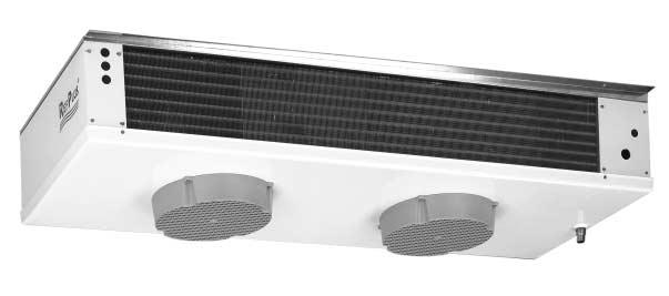
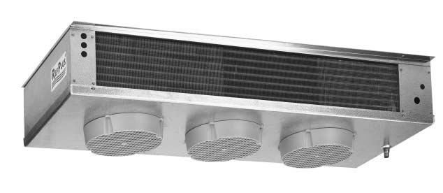
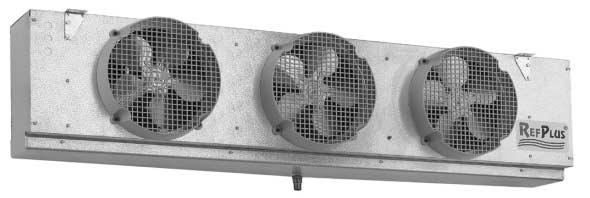
1 INSTALLATION, OPERATION & MAINTENANCE INSTRUCTIONS WALK-IN COOLERS SERIES LS-LP-LA-LV 1
2 CONTENTS SAETY CONSIDERATIONS INTRODUCTION INSTALLATION STEP 1 COMPLETE PRE-INSTALLATION CHECKS... 3 STEP 2 LOCATION STEP 3 MOUNTING STEP 4 CONNECT DRAIN LINE STEP 5 RERIGERANT CONNECTIONS STEP 6 EXPANSION VALVE CONNECTION STEP 7 WIRING START-UP LEAK TESTING AND EVACUATION AN MOTOR AN DELAY DEROST TERMINATION CONTROL AN DELAY DRAIN PAN CONTROL CHECK SUPERHEAT DEROST SYSTEM SERVICE INSPECTION CLEANING UNIT SPECIICATIONS TROUBLESHOOTING CHART TECHNICAL DATA TECHNICAL DATA (CONT D) RERIGERATION SYSTEM START-UP CHECK LIST WARRANTIES NOMENCLATURE L = Low S = Silhouette P = Profile A=Air L S A = 120/1/60 2 = 240/1/60 5 = /3/60 8 = 600/3/60 9 = 480/3/60 A = Air Defrost E = Electric Defrost G = Reverse Cycle Hot Gas Defrost W/Electric Heated Drain Pan H = Three Pipe Hot Gas Defrost W/Electric Heated Drain Pan R = Reverse Cycle Hot Gas Defrost T = Three Pipe Hot Gas Defrost Product Generation Unit 10 o T.D. 22,400 Btu/hr 2
3 SAETY CONSIDERATIONS Installing, starting up, and servicing equipment can be hazardous due to system pressures, electrical components and equipment location (roofs, elevated structures, etc.). Only trained, qualified installers and service mechanics should install, start up, and service this equipment. When working on the equipment, observe precautions in the literature and on the tags, stickers, and labels attached to the equipment. ollow all safety codes. Wear safety glasses and work gloves. Keep quenching cloths and fire extinguisher nearby when brazing. Use care in handling, rigging, and setting bulky equipment. WARNING Before installation, always check to be sure main power to systems is O. Electrical shock can cause personal injury or death. INTRODUCTION These instructions describe installation, start-up, and service for the RefPlus refrigeration unit coolers. INSTALLATION STEP 1 - COMPLETE PRE-INSTALLATION CHECKS Examine for damage incurred during shipment. ile a claim immediately with transit company if damage is found. Verify that the nameplate electrical requirements match the available power supply. Check the shipment for completeness. STEP 2 - LOCATION All unit coolers should be installed flush against the ceiling. The unit cooler must be level in all directions to ensure proper drainage of condensate. Be sure there is sufficient clearance between the ceiling and unit cooler to allow for cleaning the unit cooler top. When deciding on the location of the unit cooler, consider the following: Location of aisle racks Location relative to compressor for minimum pipe runs Location of condensate drains for minimum run The air pattern must cover the entire room Never locate unit coolers over doors or door openings Allow sufficient space between rear of unit cooler and wall to permit free return of air Avoid placement of the unit cooler directly above doors and door openings where low temperature is being maintained. Position the unit cooler so the discharge air blows above the doors. Install a baffle if door extends above the blower level. LS UNIT COOLERS These unit coolers should be located in a position where the air discharge is toward the door. The coil face on the unit cooler should be least 7 in. away from the wall. LP & LA UNIT COOLERS These unit coolers should be located in the center of the cooler with air discharge toward the back or side wall. Unit coolers with electric defrost require a 20 in. clearance at the left end when facing the fans to allow removal of defrost heaters. STEP 3 - MOUNTING Most unit coolers can be mounted with either bolts or rod hangers. Use 5/16 in. bolts and washers for unit coolers weighing up to 250 pounds. Use 3/8 in. bolts and washers for unit coolers weighing from 250 to 500 pounds. or unit coolers over 500 pounds, use 5/8 in. bolts and washers. NOTICE The unit cooler must be mounted level for proper condensate draining. Adequate support must be provided to hold the weight of the unit cooler. Note: The area above the unit must be sealed and accessible to facilitate hand cleaning without the use of tools in order to comply with National Sanitation oundation (NS) Standard 7. STEP 4 - CONNECT DRAIN LINE or all unit coolers, a drain line union is recommended for ease of installation and future servicing and should be located in close proximity to the drain pan. LS, LP & LA UNIT COOLERS A 7/8 in. ID removable drain fitting is supplied with each unit. ollow steps 1 through 4 above for connecting the drain line. OR ALL UNIT COOLERS, connect the drain line as follows: 1. Replace the rubber gasket to prevent condensate leakage. 2. Locate the union as close to the drain pan as possible. 3. Using two wrenches, tighten the drain fitting. The use of two wrenches prevents the drain fitting from twisting and damaging the unit cooler. 4. Sharply pitch the drain line and exit it through the cooler with a short run. 5. Insulate and seal the drain line where it passes through the wall. 6. Locate the drain traps in warm ambient air temperature to prevent freeze up. If the cooler temperature is below 32º, a field supplied drain line heater (15 W per foot) may be required. When installing the heater, be sure to avoid overlapping. 3
4 Drain traps on low temperature unit coolers must be outside of refrigerated enclosures. In the instance where traps are subject to freezing temperatures, wrap the traps with heat tape and insulation. Always trap drain lines individually to prevent vapor migration. STEP 5 - RERIGERANT CONNECTIONS All refrigerant system components must be installed in accordance with applicable local and national codes using proper engineering practices. Use top quality refrigeration tubing that is internally free of dirt, humidity or other contaminants. Unsealed tubing should not be used. Long radius elbows are recommended. Dry nitrogen must be swept through the lines while joints are brazed to avoid oxidation and carbon deposits. IMPORTANT The use of a calibrated pressure gauge and regulator must always be used with nitrogen gas cylinders. All external piping must be well supported. The unit cooler will not support external piping or valves. If the condition arises where the suction line must be raised to a point higher than the suction connection on the unit cooler, a suction line trap must be installed on the unit cooler. Horizontal suction lines should slope away from the evaporator toward the compressor. Leak check and evacuate the system using a two-stage deep vacuum pump. STEP 6 - EXPANSION VALVE CONNECTION All unit coolers are supplied with a 1/2 in. OD sweat expansion valve connection. Expansion valves are field supplied. LS, LP & LA unit coolers require the use of an externally equalized expansion valve and are provided with a 1/4 in. OD equalizer line. Check the operation of the expansion valve after the system has reached the desired cooler temperature. If the coil is not receiving enough refrigerant, reduce the superheat setting on the expansion valve. To ensure unit cooler performance, the expansion valve must be set at the proper superheat and at the lowest temperature in which the system is expected to operate. STEP 7 - WIRING All systems wiring must be in compliance with all applicable local and national codes. All internal wiring of fan motors, tubular heaters and combination defrost termination fan delay control have been factory connected. All wiring connections terminate on a single terminal block in the wiring compartment and are clearly labeled. START-UP CAUTION Before starting unit cooler, be sure wire fan guards are secured in place over each fan. LEAK TESTING AND EVACUATION Leak testing and evacuation must be done in accordance with local and national codes. Once all refrigerant connections are made, leak test all joints before charging the system with refrigerant. After leak testing, all moisture and non-condensable gas must be evacuated from the system. Attach high vacuum line pump and gauge on both high and low pressure sides of the system. A minimum vacuum level of 100 microns is required to effectively remove moisture. Be sure all valves such as compressor, hot gas, receiver, and liquid solenoid valves are open. Break the vacuum in the system with the refrigerant to be used. Always charge the refrigerant into the system through a new 16 cu. in drier (field supplied) in the charging manifold line. AN MOTOR The fan motor may restart on automatic thermal protection if the coils are frozen. The fan motor may cycle if the coil is blocked. Check the supply voltage at the motor leads if motor is inoperable. AN DELAY DEROST TERMINATION CONTROL This control located on the coil plate senses the coil temperature. To provide fan delay, the defrost thermostat must be turned off. 1. Set thermostat between 20º and 30º or above. 2. Adjust defrost timer up to maximum of 45 minutes. 3. Set the thermostat between 55 to 60º to defrost unit coolers operating between 40 to 20º. To defrost unit coolers operating between 10 to 10º, set the thermostat between 60 to 65º. AN DELAY DRAIN PAN CONTROL The fan delay drain pan control senses the general coil temperature. With temperature rise, the fan delay thermostat de-energizes the fan and energizes the electric pan heaters. After defrost cycle, the coil temperature drops and the fan delay thermostat energizes the motor and de-energizes the heaters. Defrost timer must be set long enough to completely melt the ice in the unit cooler. Set the thermostat at 20 to 25º and the differential at minimum. IMPORTANT After correcting a faulty defrost cycle, it is essential that the coil, drain pan and unit cooler be free and clear of ice before placing the unit cooler back on automatic operation. CHECK SUPERHEAT After the temperature has reached the desired temperature, the unit cooler superheat should be checked and adjustments made if necessary. Generally, systems with a design temperature difference (TD) of 10º should have a superheat value of 6 to 10º for maximum efficiency. or systems operating at higher TD, the superheat can be adjusted to 12 to 15º as required. 4
5 Minimum compressor suction superheat of 20º may override these recommendations on some systems with short line runs. WARNING If the condensing unit does not have flooded condenser head pressure control, then the condensing unit must have discharge pressure above the equivalent 105º condensing pressure. To properly determine the superheat of the unit cooler, follow the steps below: 1. Measure the temperature of the suction line at the point where the bulb is secured. 2. Determine the suction pressure in the suction line at the bulb location by using one of the following methods : A) Placing a gauge in the external equalized line. B) Placing a gauge directly in the suction line near the unit cooler or directly in the suction header of the unit cooler. 3. Convert the pressure reading to saturated unit cooler temperature by using a temperature pressure table. See table # Subtract the saturated temperature from the actual suction line temperature reading. The difference is superheat. An alternate method to determine superheat of the unit cooler can be used : 1. Measure the temperature of the suction line at the point where the bulb is secured (outlet). 2. Measure the temperature of one of the distributor tubes close to the unit cooler coil (inlet). 3. Subtract the inlet temperature from the outlet temperature. The difference is superheat. This method will yield accurate results as long as the pressure drop through the unit cooler coil is low. DEROST SYSTEM AIR DEROST UNIT COOLERS: an motors run continuously and a defrost time clock or low-pressure setting stops the compressor when defrost is required. The unit cooler must not be in operation more than 16 hours per day. ELECTRIC DEROST UNIT COOLER: A time clock starts the defrost process by stopping the fan and energizing the heaters. When the defrost thermostat resets the time clock, it de-energizes the heaters and re-starts the fan motors. REVERSE CYCLE HOT GAS DEROST UNIT COOLERS: Reverse cycle defrost systems introduce compressor discharge gas through the suction line during defrost. The amount of gas introduced is controlled by a solenoid bypass valve and a gas defrost time clock. Condensed refrigerant is relieved through a check valve. The check valve bypasses the expansion valve leading to the liquid line which has reduced pressure. The drain pan is warmed by the entering hot gas to avoid freezing. Defrost is initiated and terminated by the time clock. Using a suction to liquid heat exchanger is recommended. THREE PIPE HOT GAS DEROST UNIT COOLERS: During defrost, compressor discharge gas is introduced in a separate hot gas line. The amount of gas introduced is controlled by a solenoid bypass valve and a gas defrost time clock. To avoid excessive accumulation of liquid in the suction accumulator, a heat exchanger is recommended. The drain pan is warmed by the entering hot gas to avoid freezing. The time clock cycles fan motors, liquid and hot gas solenoids. A field-installed pressure regulating valve may be required on low temperature systems to control compressor crankcase pressure. SERVICE INSPECTION After one day of operation, check for any vibration in the unit cooler. All unit coolers should be checked at least once a month for proper defrosting. It may be necessary to periodically change the number of defrost cycles or adjust the duration of defrost. Under normal usage conditions, proper unit cooler maintenance should be done every six months to include the following: 1. Check all wiring and insulators. 2. Check and tighten all electrical connections. 3. Inspect contactors for proper operation and for worn contact points. 4. Check all fan motors. Tighten motor mount bolts/nuts and tighten fan set screws. 5. Clean condenser coil surface. 6. Check refrigerant and oil level in the system. 7. Check operation of the control system ensuring all safety controls are operating properly. 8. Check all defrost controls are functioning properly. 9. Clean the unit cooler coil surface. 10. Clean the drain pan and check the drain pan drain line for proper drainage. 11. Check drain line heater for proper operation, cuts and abrasions. 12. Check and tighten all flare connections. See troubleshooting chart for troubleshooting information. IMPORTANT Do not use alkaline or acidic solutions; they will damage the coils. Remove the fan guard to clean the inner face of the fan coil. CLEANING The unit cooler should be checked periodically for dirt accumulation. Grease and dust should be removed from the fan, fan guards, and drain pan. Occasional cleaning of finned surfaces can be done by dusting the fins and then cleaning with a mild detergent and warm water spray. Always pressure clean in reverse of the air flow.
6 UNIT SPECIICATIONS OR ALL UNITS: - or R-134a or R-22 refrigerant charge, multiply R-404 by Operating charge is based on 30% liquid and 70% vapor at 25º suction. LS SERIES: - Use LSR model for hot gas reverse cycle defrosts. - Use LST model for hot gas three pipe defrost with gas drain pan. - Air throw for LS Series: 25 to 35 feet. LP SERIES: - Use LPG model for hot gas reverse cycle defrost with electric drain pan. - Use LPH model for hot gas three pipe defrost with electrical drain pan. - Air throw for LP Series: 12 to 18 feet on each side. LA SERIES: - Use LAG model for hot gas reverse cycle defrost with electric drain pan. - Use LAH model for hot gas three pipe defrost with electric drain pan. - Air throw for LA Series: 10 to 15 feet on each side. TROUBLESHOOTING CHART SYMPTOMS POSSIBLE CAUSES POSSIBLE CORRECTIVE STEPS an(s) will not operate 1. Main switch open 1. Close switch 2. Blown fuses 2. Replace fuses. Check for short circuits 3. Defective motor or overload conditions. 4. Defective timer or defrost thermostat 3. Replace motor 5. Unit in defrost cycle 4. Replace defective component 6. Coil does not get cold enough to reset thermostat 5. Wait for completion of cycle 6. Adjust fan delay setting of thermostat Room temperature too high 1. Room thermostat set too high 1. Adjust thermostat 2. Superheat too high 2. Adjust thermal expansion valve 3. System low on refrigerant 3. Add refrigerant 4. Coil iced-up 4. Manually defrost coil and check defrost controls for malfunctions Ice accumulating on ceiling 1. Defrost duration is too long 1. Adjust defrost termination thermostat around evaporator and/or on 2. an delay not delaying fans after defrost period 2. Defective defrost thermostat or not adjusted properly fan guards, venturi, or blades 3. Defective defrost thermostat or timer 3. Replace defective components 4. Too many defrosts 4. Reduce number of defrost Coil not clearing of frost 1. Coil temperature not getting above 1. Check heater operation during defrost cycle freezing point during defrost 2. Adjust timer for more defrost cycles 2. Not enough defrost cycles per day 3. Adjust defrost thermostat or timer for longer cycle 3. Defrost cycle too short 4. Replace defective component 4. Defective timer or defrost thermostat Ice accumulating in drain pan 1. Defective heater 1. Replace heater 2. Unit not pitched properly 2. Check pitch and adjust if necessary 3. Drain line plugged 3. Clean drain line 4. Defective drain line heater 4. Replace heater 5. Defective timer or thermostat 5. Replace defective component 6
7 COMMERCIAL WALK-IN COOLERS LS, LP, LA LOW SILHOUETTE SUIX-1 120/1/60 SUIX-2 240/1/60 MOTOR All Models RMT 0004 RMT 0005 LS AN BLADE LP, LA RN 0023 RN 0022 AN GUARD ALL MODELS RGR RGR Note: Motors are mounted in sheet metal base. Motors include RHW 1999 (4) 1 Standard plastic guard 2 Optional steel wire guard MODEL LSE LPE(G) (H) LAE(G) (H) ELECTRIC DEROST HEATER SUIX 1, 2 & 5 SUIX 8 & 9 REH 0010 N/A REH 0020 N/A REH 0030 REH REH 0040 REH REH 0050 REH 0090 REH 0060 REH 0097 REH 0070 REH 0100 Note: All electric defrost units (E) use 4 coil heaters and 2 drain pan heaters All gas defrost units (G) (H) use 2 drain pan heaters DEROST CONTROL All Models R&T G&H E DEROST TERMINATION RTH 0002 AN DELAY RTH 0003 PAN HEATER SAETY N/A Note: 1 RTH 0009 for optional LS Medium & Low Temperature (LS) RTH (LP, LA) RTH 0009 RTH 0002 RTH 0002 N/A DRAIN ITTING KIT All Models DK-2 Note: DK-2 includes RHW 4007, RHW 2011 & RT 5135 TERMINAL BLOCK All Models REM 0004 WIRING HARNESS All Models REW 0020 REW 0030 REW
8 TECHNICAL DATA (LS SERIES) Model R404A, R507 Operating Charge (lb.) Shipping Weight (lb.) LSA LSA LSA LSA LSA LSA LSA LSA LSA LSA LSA LSE LSE LSE LSE LSE LSE LSE LSE LSE LSE LS(R)(T) LS(R)(T) LS(R)(T) LS(R)(T) LS(R)(T) LS(R)(T) LS(R)(T) LS(R)(T) LS(R)(T) LS(R)(T) TECHNICAL DATA (LP SERIES) Model R404A, R507 Operating Charge (lb.) Shipping Weight (lb.) LPA LPA LPA LPA LPA LPA LPA LPA LPA LPA LPE LPE LPE LPE LPE LPE LPE LPE LPE LPE
9 TECHNICAL DATA (LP SERIES) Model R404A, R507 Operating Charge (lb.) Shipping Weight (lb.) LP(G)(H) LP(G)(H) LP(G)(H) LP(G)(H) LP(G)(H) LP(G)(H) LP(G)(H) LP(G)(H) LP(G)(H) LP(G)(H) TECHNICAL DATA (LA SERIES) Model R404A, R507 Operating Charge (lb.) Shipping Weight (lb.) LAA LAA LAA LAA LAA LAA LAA LAA LAA LAA LAE LAE LAE LAE LAE LAE LAE LAE LAE LAE LA(G)(H) LA(G)(H) LA(G)(H) LA(G)(H) LA(G)(H) LA(G)(H) LA(G)(H) LA(G)(H) LA(G)(H) LA(G)(H) Note: Operating charges are based on 30% liquid, 70% vapor at 25º suction an motor heat is not included in rating, add 342 BTUH (100W) per fan motor to room load Use suffix 1 for 120/1/60, suffix 2 for 240/1/60 or /1/50 use suffix 2 and multiply capacity by 0.92 or R134a or R-22 refrigerant charge, multiply R-404A by Air throw for LS Series is 25 to 35 feet Air throw for LP Series is 12 to 18 feet Air throw for LA Series is 10 to 15 feet 9
10 1. PRELIMINARY INORMATION UNIT COOLER MODEL No.: UNIT COOLER MODEL No.: CONDENSING UNIT MODEL No.: COMPRESSOR MODEL No.: COMPRESSOR MODEL No.: DATE: SERIAL No.: SERIAL No.: SERIAL No.: SERIAL No.: SERIAL No.: TECHNICIAN: 2. PRE-START-UP (Check each item when completed) CHECK ALL ELECTRICAL CONNECTIONS AND TERMINALS OR TIGHTNESS VERIY RERIGERANT CHARGE USING CHARGING CHART LABEL ON CONDENSING UNIT CHECK RERIGERANT AND OIL LEVEL IN SYSTEM VERIY THAT ALL DEROST CONTROLS ARE UNCTIONING PROPERLY CHECK ALL AN MOTORS AND MOTOR MOUNTS OR TIGHTNESS CHECK DRAIN LINES AND DRAIN PAN OR PROPER DRAINAGE CHECK DRAIN LINE HEATER OR PROPER OPERATION CHECK ALL LARE CONNECTIONS OR TIGHTNESS 3. START-UP ELECTRICAL COMPRESSOR VOLTAGE L1 - L2 L2 - L3 L3 - L1 COMPRESSOR AMPS L1 L2 L3 COMPRESSOR UNIT COOLER VOLTS VOLTS PHASE PHASE HERTZ HERTZ TEMPERATURE AMBIENT TEMPERATURE DESIGN BOX TEMPERATURE OPERATING BOX TEMPERATURE OPERATING BOX TEMPERATURE SUPERHEAT AT COMPRESSOR SUCTION LINE TEMP. AT UNIT COOLER SUPERHEAT AT UNIT COOLER START-UP ATER 24 HOURS O OPERATION PRESSURES (in cooling mode) RERIGERANT SUCTION PSIG TEMP AT COMPRESSOR RERIGERANT DISCHARGE PSIG TEMP AT COMPRESSOR EVACUATION: NUMBER TIMES INAL MICRON UNIT COOLER DRAIN LINE TRAPPED OUTSIDE O BOX: YES OR NO 4. CONTROLS THERMOSTAT SETTING DEROST SETTING /DAY /DAY MINUTES AIL-SAE MINUTES AIL-SAE 5. IELD INSTALLED EXPANSION VALVE MANUACTURER MODEL 10
11 WARRANTIES RefPlus warrants the labeled (Serial No.) new RefPlus equipment and all parts thereof, to be free from defects in workmanship and material at the time of purchase. Applies to original purchaser only (nontransferable). Under this warranty RefPlus shall be limited to repairing or exchanging any parts, without charge OB factory or nearest authorized parts wholesalers, which may prove defective to the satisfaction of RefPlus, within one year from date of start-up, not to exceed eighteen (18) months from date of shipment from the factory. The warranties to repair or replace as recited, are the only warranties, express, implied, or statutory, made by RefPlus. No express or implied warranties as to merchantability or fitness for a particular purpose or use. RefPlus neither assumes, nor authorizes any person to assume for it, any other obligation or liability in connection with the sale of said equipment or any part thereof. REPLUS SHALL NOT BE LIABLE: 1 - or any repairs or replacement by buyer without the written consent of RefPlus, or when the equipment is installed or operated in a manner contrary to the instructions covering installation and service which accompanied such equipment. 2 - or any damages, delays, or losses, direct or consequential, caused by defects, nor for damages caused by short or reduced supply of materials, fire, flood, strikes, acts of God, or circumstances beyond its control. 3 - When the failure or defect of any part or parts is incidental to ordinary wear, accident, abuse or misuse; or when the serial number of the equipment has been removed, defaced, altered, or tampered with. 4 - When this equipment is operated on low or improper voltages. 5 - or payment of any removal or installation charges of parts or units. 6 - When this equipment is moved to a different location other than the original installation. EXCLUSIONS THIS WARRANTY SHALL NOT APPLY TO LOSS O OOD OR RERIGERANT DUE TO AILURE OR ANY REASON. RefPlus reserves the right to make any changes in the design or specifications of any product at any time without notice. 11
12 WI/O&M R0-3K Printed in Canada. USA & CANADA De Coulomb, Boucherville, Quebec Canada J4B 7L8 Tel.: (450) ax: (450)
& MAINTENANCE INSTRUCTIONS INSTALLATION, OPERATION INDUSTRIAL COOLERS & FREEZERS WALK-IN COOLERS SERIES: EK, EM, EH, EI, EB, EF
 INSTALLATION, OPERATION & MAINTENANCE INSTRUCTIONS INDUSTRIAL COOLERS & REEZERS WALK-IN COOLERS SERIES: EK, EM, EH, EI, EB, E MODELS: EKA, EKE, EKR, EKT EKA, EKE, EKR, EKT K = Compact Profile EMA, EME,
Installation, Operation, and Maintenance Information
 Installation, Operation, and Maintenance Information Low Velocity Unit Coolers Bulletin No. IOM 110.3 Table of Contents Inspection... 2 Installation... 2 4 General... 2 Location... 2 Drain Line... 3 Refrigerant
Condensing Unit Installation and Operating Instructions
 Bulletin WCU_O&I 01 June 2003 Condensing Unit Installation and Operating Instructions WCU Air Cooled Condensing Unit Table of Contents Section 1. Section 2. Section 3. Section 4. Section 5. Section 6.
KR Electrical Defrost Unit Coolers (PN E108318_E)
") KR Series Electric Defrost Unit Coolers Operating and Installation Manual KR Electrical Defrost Unit Coolers (PN E108318_E) TABLE OF CONTENTS 1 LOCATION RECOMMENDATIONS... 2 2 UNIT MOUNTING... 2 3 DRAIN
KR Series Electric Defrost Unit Coolers Operating and Installation Manual KR Electrical Defrost Unit Coolers (PN E108318_E) TABLE OF CONTENTS 1 LOCATION RECOMMENDATIONS... 2 2 UNIT MOUNTING... 2 3 DRAIN
ThermoSaver TM Hot Gas Defrost System
 PRODUCT DATA, APPLICATION & INSTALLATION GUIDE Supplement to Condensing Unit Installation and Maintenance Manual Bulletin B40-THERM-PDI-14 1069132 ThermoSaver TM Hot Gas Defrost System For use on select
INSTALLATION, OPERATION & MAINTENANCE INSTRUCTIONS FOR LOW PROFILE-UNIT COOLERS AND DUAL FLOW UNIT COOLER
 INSTALLATION, OPERATION & MAINTENANCE INSTRUCTIONS FOR LOW PROFILE-UNIT COOLERS AND DUAL FLOW UNIT COOLER SERIES LPA SERIES LPE SERIES LPG SERIES LPH AIR DEFROST APPLICATION ELECTRIC DEFROST APPLICATION
KR Series Air Defrost Unit Coolers Operating and Installation Manual
 KR Series Air Defrost Unit Coolers Operating and Installation Manual KR Air Defrost Unit Coolers (PN E108317_L) TABLE OF CONTENTS 1 RECEIPT OF EQUIPMENT... 2 1.1 INSPECTION... 2 1.2 LOSS OF GAS HOLDING
REFRIGERATED DROP-INS (2-6)FT-DI Installation and Operating Manual
FT-DI Installation and Operating Manual") REFRIGERATED DROP-INS (2-6)FT-DI Installation and Operating Manual For service information call 800-544-3057 Please have the following information available before calling. Information can be found on
REFRIGERATED DROP-INS (2-6)FT-DI Installation and Operating Manual For service information call 800-544-3057 Please have the following information available before calling. Information can be found on
WMHP Series R410a Heat Pump INSTALLATION INSTRUCTIONS
 WMHP Series R410a Heat Pump INSTALLATION INSTRUCTIONS **WARNING TO INSTALLER, SERVICE PERSONNEL AND OWNER** Altering the product or replacing parts with non authorized factory parts voids all warranty
Condensing Unit Installation and Operating Instructions
 Bulletin ACU_O&I 02 August 2016 Condensing Unit Installation and Operating Instructions ACU Air Cooled Condensers Table of Contents Section 1. General Information... 2 Section 2. Refrigeration Piping...
TABLE OF CONTENTS. NOTE: Read the entire instruction manual before starting the installation. TROUBLESHOOTING... 13
 R 410A Duct Free Split System Air Conditioner and Heat Pump Product Family: DFS4(A/H) System, DFC4(A/H)3 Outdoor, DFF4(A/H)H Indoor NOTE: Read the entire instruction manual before starting the installation.
High Profile Evaporator
 PRODUCT DATA & INSTALLATION Bulletin K30-KHPA-PDI-5 Part # 1081585 PRODUCT SUPPORT web: k-rp.com/khp email: evaps@k-rp.com call: 1-844-893-3222 x520 scan: High Profile Evaporator High & Medium Temperature
CS/CD/CP AIR COOLED CONDENSING UNITS (P/N E207120C R2)
") CS*/CD*/CP* Series Air Cooled Condensing Units Operating and Installation Manual CS/CD/CP AIR COOLED CONDENSING UNITS (P/N E207120C R2) TABLE OF CONTENTS I. Receipt of Equipment 2 II. Piping...4 III. System
CS*/CD*/CP* Series Air Cooled Condensing Units Operating and Installation Manual CS/CD/CP AIR COOLED CONDENSING UNITS (P/N E207120C R2) TABLE OF CONTENTS I. Receipt of Equipment 2 II. Piping...4 III. System
INSTALLATION AND OPERATING MANUAL
 INSTALLATION AND OPERATING MANUAL Refrigerated Island Merchandiser FOR PARTS & SERVICE Contact: Piper Products, Inc. Phone: (800) 544-3057 Ask for Service Department IMPORTANT! This manual contains important
INSTALLATION AND OPERATING MANUAL
 INSTALLATION AND OPERATING MANUAL Refrigerated Merchandisers with Air-Over Displays Refrigerated Low-Profile Mobile Merchandiser Refrigerated High-Profile Mobile Merchandiser Refrigerated Grab-N-Go Merchandiser
WKS 4000 SERIES (USA only) --INSTALLATION INSTRUCTIONS--
 --INSTALLATION INSTRUCTIONS--") 8610 Production Avenue San Diego, California 92121 (858) 566-7465 Fax (858) 566-1943 WKS 4000 SERIES (USA only) --INSTALLATION INSTRUCTIONS-- Thank you for choosing a BREEZAIRE cooling unit. We believe
8610 Production Avenue San Diego, California 92121 (858) 566-7465 Fax (858) 566-1943 WKS 4000 SERIES (USA only) --INSTALLATION INSTRUCTIONS-- Thank you for choosing a BREEZAIRE cooling unit. We believe
DLCLRA. INSTALLATION INSTRUCTIONS Outdoor Unit Single Zone Ductless System Sizes 36 to 58 TABLE OF CONTENTS
 DLCLRA INSTALLATION INSTRUCTIONS Outdoor Unit Single Zone Ductless System Sizes 36 to 58 Fig. 1 - Size 36 TABLE OF CONTENTS PAGE SAFETY CONSIDERATIONS... 2 PARTS LIST... 3 SYSTEM REQUIREMENTS... 4 WIRING...
PARALLEL RACK SYSTEM INSTALLATION & OPERATIONS MANUAL With Master Rack Compressor Sequencer
 PARALLEL RACK SYSTEM INSTALLATION & OPERATIONS MANUAL With Master Rack Compressor Sequencer 5/16 Rev. A 57-02509 2 Contents INTRODUCTION... 4 WARNING LABELS AND SAFETY INSTRUCTIONS... 5 PS SERIES PARALLEL
Horizontal Bottle Cooler Installation and Operation Manual
 Speeds Up the Pace of Innovation Horizontal Bottle Cooler Installation and Operation Manual Please read this manual completely before attempting to install or operate this equipment! TBC-50SD, 50SB/ TBC-95SD,
RPI Industries, Inc.
 IMPORTANT: THE FOLLOWING INFORMATION SHOULD BE RETAINED FOR FUTURE REFERENCE RPI Industries, Inc. building a better case for sales BAKERY and DELI USE AND SERVICE MANUAL WARRANTY INFORMATION SPECIFICATIONS
Electrical Problems. Fuse(s) blow or circuit breaker trips. Does the unit use circuit breakers or fuses? Replace with correct fuse(s)
 blow or circuit breaker trips. Does the unit use circuit breakers or fuses? Replace with correct fuse(s)") Electrical Problems Fuse(s) blow or circuit breaker trips Does the unit use circuit breakers or fuses? Fuse(s) Circuit breakers Are the fuses dual element time delay? Is the circuit breaker HACR rated?
Electrical Problems Fuse(s) blow or circuit breaker trips Does the unit use circuit breakers or fuses? Fuse(s) Circuit breakers Are the fuses dual element time delay? Is the circuit breaker HACR rated?
G Series. G Series Air Coils Installation ti Manual ENCASED/UNCASED AIR COILS. Geothermal/Water Source Heat Pumps R-410A Refrigerant 2-5 Ton
 G Series ENCASED/UNCASED AIR COILS Geothermal/Water Source Heat Pumps R-410A Refrigerant 2- Ton Dimensional Data G Series Air Coils Installation ti Manual Installation Information Maintenance IM1018AG1
Turbo Air Speed up the Pace of Innovation TBB-4SB CAUTION! PLEASE KEEP POWER SWITCH ON BEFORE OPERATING THIS EQUIPMENT
 Turbo Air Speed up the Pace of Innovation CAUTION! PLEASE KEEP POWER SWITCH ON BEFORE OPERATING THIS EQUIPMENT Underbar Equipment Back Bars Installation and Operation Manual Please read this manual completely
Installation Instructions
 38MHR Outdoor Unit Single Zone Ductless System Sizes 09 to 24 Installation Instructions NOTE: Read the entire instruction manual before starting the installation. NOTE: Images are for illustration purposes
Installation Instructions
 8GXM / 0GXM Multi---Split High---Wall Duct Free Split System 8GXM --- Size 18k, k, and 0k 0GXM --- Size 9k, 1k, and 18k Installation Instructions NOTE: Read the entire instruction manual before starting
RPI Industries, Inc.
 RPI Industries, Inc. AIR SCREEN and SELF-SERVE OPERATION AND SERVICE MANUAL WARRANTY INFORMATION For Models Stratus SCRFC48R-SSI SCRFC60R-SSI SCRFC72R-SSI SCRFC48R-SSII SCRFC72R-SSII SCRFC48R-SSIII SCRFC72R-SSIII
Unit Coolers. Installation and Operations Manual. Table of Contents. H-IM-UC November 2017 Part No
 Installation and Operations Manual H-IM-UC November 2017 Part No. 25008201 Replaces ugust 2012 Unit Coolers Table of Contents General Safety Information...2 Inspection...2 Warranty Statement...2 Placement...2
INSTALLATION, OPERATION & MAINTENANCE INSTRUCTIONS FOR INDUSTRIAL COOLERS
 INSTALLATION, OPERATION & MAINTENANCE INSTRUCTIONS FOR INDUSTRIAL COOLERS SERIES MPA, HPA SERIES MPE, HPE & JPE SERIES MPG, HPG & JPG SERIES MPH, HPH & JPH AIR DEFROST APPLICATION ELECTRIC DEFROST APPLICATION
INSTALLATION INSTRUCTIONS TXV Horizontal Duct Coils EHD
 TXV Horizontal Duct s EHD These instructions must be read and understood completely before attempting installation. It is important that the Blower and Duct System be properly sized to allow the system
RPI Industries, Inc.
 RPI Industries, Inc. AIR SCREEN and SELF-SERVE OPERATION AND SERVICE MANUAL WARRANTY INFORMATION For Models Olympus Bandit Bravo SCAS36R SCRFC3660R SCRFC3648R SCAS48R SCRFC4860R SCRFC4848R SCAS60R SCRFC6060R
INSTALLATION INSTRUCTIONS TXV Horizontal Slab Coils WLSH
 TXV Horizontal Slab Coils WLSH These instructions must be read and understood completely before attempting installation. It is important that the Blower and Duct System be properly sized to allow the system
38ASB/CCARS240~600 (036~060) AIR-COOLED CONDENSING UNIT
 AIR-COOLED CONDENSING UNIT") Concepcion Carrier Air conditioning Company Philippines INSTALLATION, START-UP AND SERVICE INSTRUCTIONS 38ASB/CCARS240~600 (036~060) AIR-COOLED CONDENSING UNIT CONTENTS Safety Considerations 1 Complete
Concepcion Carrier Air conditioning Company Philippines INSTALLATION, START-UP AND SERVICE INSTRUCTIONS 38ASB/CCARS240~600 (036~060) AIR-COOLED CONDENSING UNIT CONTENTS Safety Considerations 1 Complete
XSTREAM Valve System With A.R.M.E.D. Technology Service & Installation Instructions Page 1
 Page 1 WHY should I install the XSTREAM Valve System? XDX is more efficient, saving on power consumption. Use of XDX system decreases defrost cycles. XDX maintains more consistent product temperatures,
WineZone Ceiling Mount Ductless Split 15
 WineZone Ceiling Mount Ductless Split 15 Requires an HVAC technician to install and charge with R-22 refrigerant. Easy to install. Unit plugs into wall outlet. Industrial grade unit for longer life. Indoor
DOLE REFRIGERATING COMPANY 1420 Higgs Road Lewisburg, Tennessee Phone (931)
") DOLE REFRIGERATING COMPANY 1420 Higgs Road Lewisburg, Tennessee 37091 Phone (931) 359-6211 1-800-251-8990 www.doleref.com PHO WATER DEFROST OPERATION & MAINTENANCE MANUAL June 2002 PHO WATER DEFROST Table
DOLE REFRIGERATING COMPANY 1420 Higgs Road Lewisburg, Tennessee 37091 Phone (931) 359-6211 1-800-251-8990 www.doleref.com PHO WATER DEFROST OPERATION & MAINTENANCE MANUAL June 2002 PHO WATER DEFROST Table
Installation Instructions
 PREFERREDT SERIES AIR CONDITIONER WITH PURONR REFRIGERANT 1-1/2 TO 5 NOMINAL TONS Installation Instructions Fig. 1 --- 538A NOTE: Read the entire instruction manual before starting the installation. TABLE
Installation Instructions
 24AHA4 Performance Series Air Conditioner with Puron Refrigerant 1-1/2 to 5 Nominal Tons Installation Instructions Fig. 1-24AHA4 A07532 SAFETY CONSIDERATIONS Improper installation, adjustment, alteration,
AIR CONDITIONER ELECTRONIC CONTROL
 READ AND SAVE THESE INSTRUCTIONS AIR CONDITIONER ELECTRONIC CONTROL ROOM AIR CONDITIONER WARRANTY Your product is protected by this warranty Your appliance is warranted by Electrolux. Electrolux has authorized
R E D I C O N T R O L S
 R E D I C O N T R O L S File Literature Number 1144-01-1 Installation Operation & Maintenance Manual CONTINUOUS REFRIGERANT DEHYDRATOR Model: CD-120 For use with Refrigerants R-11, R-123, R-12, R-22, R-134a
POLAR TEMP FARM MORTALITY UNIT OPERATION MANUAL
 POLAR TEMP FARM MORTALITY UNIT OPERATION MANUAL www.polartemp.com TABLE OF CONTENT Disclaimer.......................................... Page 3 Inspection, unpacking and FMU setup.................. Page
Installation Instructions
 Performance Series Heat Pumps with PURONr Refrigerant 1 --- 1/2 to 5 Nominal Tons Installation Instructions Fig. 1 --- A07532 NOTE: Read the entire instruction manual before starting the installation.
Installation, Start-Up and Service Instructions
 38AH044-134 Air-Cooled Condensing Units 50/60 Hz Installation, Start-Up and Service Instructions CONTENTS Page SAFETY CONSIDERATIONS...................... 1 INSTALLATION................................
Refrigerator Freezer Installation and Operation Manual
 Speeds Up the Pace of Innovation CAUTION! Refrigerator Freezer Installation and Operation Manual PLEASE KEEP POWER SWITCH ON BEFORE OPERATING THIS EQUIPMENT Please read this manual completely before attempting
RPI Industries, Inc.
 IMPORTANT: THE FOLLOWING INFORMATION SHOULD BE RETAINED FOR FUTURE REFERENCE RPI Industries, Inc. building a better case for sales CONFECTIONERY USE & SERVICE MANUAL WARRANTY INFORMATION For Models Bradford
Residential Piping and Long Line Guideline
 AC / HP R-410A Refrigerant Systems Single-Stage, Two-Stage and Variable Speed Models Residential Piping and Long Line Guideline TABLE OF CONTENTS Safety Considerations... 2 Definitions... 2 Introduction...
MYSTICOOL Max Valve System with Xstream and A.R.M.E.D. Technology Service & Installation Instructions Page 1
 Page 1 WHY should I install the MYSTICOOL Max Valve System? XDX is more efficient, saving on power consumption. Use of XDX system decreases defrost cycles. XDX maintains more consistent product temperatures,
Service Step by Step Trouble-Shooting Check-List
 WARNING: Only Data Aire trained technician or experience technicians should be working on Data Aire Equipment. Protect yourself at all times and work safe. Date: Dates at the job site: From: to Job#: Serial#:
Installation Instructions
 CNPVP CNRVP Cased N Coils Upflow --- Downflow Heating --- Cooling Installation Instructions NOTE: Read the entire instruction manual before starting the installation. TABLE OF CONTENTS PAGE SAFETY CONSIDERATIONS...
Installation Instructions
 CNPVP CNRVP Cased N Coils Upflow --- Downflow Heating --- Cooling Installation Instructions NOTE: Read the entire instruction manual before starting the installation. TABLE OF CONTENTS PAGE SAFETY CONSIDERATIONS...
Owner s Manual Refrigerated Compressed Air Dryers Models F-200, 250, 300 & F350
 Owner s Manual Refrigerated Compressed Air Dryers Models F-200, 250, 300 & F350 Read carefully before attempting to assemble, install, operate or maintain the product described. Protect yourself and others
Condensing Unit and Refrigeration System Installation & Operations Manual R448A/R449A
 Condensing Unit and Refrigeration System Installation & Operations Manual R448A/R449A 57-06 REV. -04-7_BJ TABLE OF CONTENTS INTRODUCTION... WARNING LABELS AND SAFETY INSTRUCTIONS...4 M-SERIES CONDENSING
OPERATING INSTRUCTIONS
 OPERATING INSTRUCTIONS SPECIALTY REFRIGERATED TRANSPORT CABINETS FOR SATELLITE LOCATIONS RBQ-96 Caution: Read the instructions before using the machine. CONGRATULATIONS......and thank you for purchasing
KTL Two-Way Low Profile Evaporators
 PRODUCT DATA & INSTALLATION Bulletin K30--PDI-16 Part # 87830 PRODUCT SUPPORT web: k-rp.com/ktl email: evaps@k-rp.com call: 1-844-893-3222 x520 scan: Two-Way Low Profile Evaporators High, Medium and Low
OPERATION AND MAINTENANCE INSTRUCTIONS FOR ROOF TOP HEAT PUMPS AND CEILING PLENUMS
 OPERATION AND MAINTENANCE INSTRUCTIONS FOR ROOF TOP HEAT PUMPS AND CEILING PLENUMS TABLE OF CONTENTS I. General Information.................................................. 2 II. Standard Ceiling Plenum
OWNER/OPERATOR MANUAL COMPONENTS, INSTALLATION, OPERATION AND SERVICE INSTRUCTIONS
 OWNER/OPERATOR MANUAL COMPONENTS, INSTALLATION, OPERATION AND SERVICE INSTRUCTIONS REFRIGERATED COMPRESSED AIR DRYER WRA-0050 WRA-0200 WARNING READ ALL INFORMATION IN THIS MANUAL BEFORE BEGINNING INSTALLATION
INSTALLATION AND OPERATING MANUAL
 INSTALLATION AND OPERATING MANUAL Refrigerated Cases with Air-Over Displays Refrigerated High Profile Grab-N-Go FOR PARTS & SERVICE Contact: Piper Products, Inc. Phone: (800) 544-3057 Ask for Service Department
INSTALLATION INSTRUCTIONS TXV Horizontal Duct Coils EHD
 TXV Horizontal Duct s EHD These instructions must be read and understood completely before attempting installation. It is important that the Blower and Duct System be properly sized to allow the system
CHEST FREEZER INSTRUCTION MANUAL. Model No.: EWCF5WBX EWCF7WBX
 CHEST FREEZER INSTRUCTION MANUAL Model No.: EWCF5WBX EWCF7WBX To ensure proper use of this appliance and your safety, please read the following instructions completely before operating this appliance.
Milk Coolers Installation and Operation Manual Please read this manual completely before attempting to install or operate this equipment!
 Turbo Air Speed up the Pace of Innovation CAUTION! PLEASE KEEP POWER SWITCH ON BEFORE OPERATING THIS EQUIPMENT Milk Coolers Installation and Operation Manual Please read this manual completely before attempting
Owner s Manual Refrigerated Compressed Air Dryer Model F-50
 Owner s Manual Refrigerated Compressed Air Dryer Model F-50 Read carefully before attempting to assemble, install, operate or maintain the product described. Protect yourself and others by observing all
INSTRUCTIONN MANUAL. for Angle Curved MMF9106 MMF9109 MMF9112
 INSTRUCTIONN MANUAL for Angle Curved Top Chest Freezer MMF9106 MMF9109 MMF9112 Please read this user s manual thoroughly before using. Keep this manual handy for further reference. Email: Service@atosausa.com
EBAC MODEL CD30 INDUSTRIAL DEHUMIDIFIER OWNER S MANUAL
 EBAC MODEL CD30 INDUSTRIAL DEHUMIDIFIER OWNER S MANUAL Ebac Industrial Products, Inc. 700 Thimble Shoals Blvd, Suite 109 Newport News, VA. 23606-2575 Tel: (757) 873 6800 Fax: (757) 873 3632 Website www.ebacusa.com
IMPORTANT SAFETY INFORMATION:
 Owner s Manual Model CUH05B31T IMPORTANT SAFETY INFORMATION: Always read this manual first before attempting to install or use this heater. For your safety, always comply with all warnings and safety instructions
Refrigerator Freezer Installation and Operation Manual
 Speeds Up the Pace of Innovation CAUTION! PLEASE KEEP POWER SWITCH ON BEFORE OPERATING FREEZER Refrigerator Freezer Installation and Operation Manual Please read this manual completely before attempting
SLIDER CASEMENT AIR CONDITIONER
 OWNER S GUIDE READ AND SAVE THESE INSTRUCTIONS SLIDER CASEMENT AIR CONDITIONER ROTARY CONTROL P/N 309000854 (11/03) ROOM AIR CONDITIONER WARRANTY Your product is protected by this warranty Your appliance
Standard and CELDEK Evaporative Cooler Modules Installation, Operation, and Maintenance Manual
 Standard and CELDEK Evaporative Cooler Modules Installation, Operation, and Maintenance Manual Standard Evaporative Cooler CELDEK Evaporative Cooler RECEIVING AND INSPECTION Upon receiving unit, check
38GHP AIR-COOLED MULTI SPLIT CONDENSING UNITS
 Concepcion Carrier Air conditioning Company Philippines INSTALLATION MANUAL, START-UP & SERVICE INSTRUCTIONS 38GHP AIR-COOLED MULTI SPLIT CONDENSING UNITS CONTENTS: Physical Data and Dimensions........
Standard and CELDEK Evaporative Cooler Modules Installation, Operation, and Maintenance Manual
 Standard and CELDEK Evaporative Cooler Modules Installation, Operation, and Maintenance Manual Standard Evaporative Cooler CELDEK Evaporative Cooler RECEIVING AND INSPECTION Upon receiving unit, check
Frosty Factory of America, Inc.
 Frosty Factory of America, Inc. 2301 S. Farmerville St., Ruston, LA 71270 frostyfactory.com (318) 255-1162 (800) 544-4071 (318) 255-1170 fax Auto Fill System & Tank Service Manual All technical data, pictures
1.7 CU.FT. REFRIGERATOR INSTRUCTION MANUAL MCBR170BMD
 1.7 CU.FT. REFRIGERATOR INSTRUCTION MANUAL Model No.: MCBR170WMD MCBR170BMD To ensure proper use of this appliance and your safety, please read the following instructions completely before operating this
SM/SV-Space Master Unit Coolers (E R.0)
") SM/SV Series Space Master Unit Coolers Operating and Installation Manual SM/SV-Space Master Unit Coolers (E316008 R.0) TABLE OF CONTENTS 1 RECEIPT OF EQUIPMENT 3 1.1 INSPECTION 3 1.2 LOSS OF GAS HOLDING
SM/SV Series Space Master Unit Coolers Operating and Installation Manual SM/SV-Space Master Unit Coolers (E316008 R.0) TABLE OF CONTENTS 1 RECEIPT OF EQUIPMENT 3 1.1 INSPECTION 3 1.2 LOSS OF GAS HOLDING
ref. com Owner s Manual for models: A Step Above the Standard Thank you for choosing EVEREST
 www.everest ref. com Owner s Manual for models: Back Bar Coolers " Deep Back Bar Coolers Glass Door Back Bar Coolers " Deep Galss Door Back Bar Coolers " Deep Galss Sliding Door Back Bar Coolers EBB3,
Installation, Operation, and Maintenance Information
 Installation, Operation, and Maintenance Information Air Cooled Condensers 8-2016 Rev 0 Table of Contents General Safety Information 2 Inspection 2 Installation 2 6 Rigging and Assembly 2 Unit Location
INSTRUCTIONS! DO NOT DISCARD!
 INSTRUCTIONS! DO NOT DISCARD! CAUTION! Do NOT install where injury might occur due to Moving parts, Sharp corners, Hot surfaces or electrical components d N0417 Page 1 of 10 INSTALLATION INSTRUCTIONS CAUTION
INSTALLATION INSTRUCTIONS
 2008 Lennox Industries Inc. Dallas, Texas, USA INSTALLATION INSTRUCTIONS CH33 Series Units EVAPORATOR COILS 505,264M (65484504) 05/08 Supersedes 10/07 Litho U.S.A. RETAIN THESE INSTRUCTIONS FOR FUTURE
CWR265SZ 26 Bottle Built-in Wine Cooler Owner s Manual
 CWR265SZ 26 Bottle Built-in Wine Cooler Owner s Manual This owner s manual provides instructions on safe installation use, and troubleshooting assistance. Please read it carefully and save it for reference
IOM 410. Installation Operation Maintenance Information. UNIT COOLERS Super-Flo (SD Models) Easy-Flo (EF Models) Table of Contents
 Easy-Flo (EF Models) Table of Contents") IOM 410 Installation Operation Maintenance Information UNIT COOLERS Super-Flo (SD Models) Easy-Flo (EF Models) Air, Electric & Hot Gas Defrost Table of Contents Inspection..........................................
IOM 410 Installation Operation Maintenance Information UNIT COOLERS Super-Flo (SD Models) Easy-Flo (EF Models) Air, Electric & Hot Gas Defrost Table of Contents Inspection..........................................
MANUAL 8/12/05. Model BKP TM 100 INSTALLATION, OPERATION & MAINTENANCE. Commercial High Efficiency Heat Pipe Dehumidifier
 MANUAL 8/12/05 INSTALLATION, OPERATION & MAINTENANCE Commercial High Efficiency Heat Pipe Dehumidifier Model BKP TM 100 Heat Pipe Technology, Inc. 6904 Parke East Blvd. Tampa FL 33610 Tel: (813) 470-4250
Operation and Maintenance Manual
 Warranty Information Ritchie Engineering guarantees YELLOW JACKET products to be free of defective material and workmanship which could affect the life of the product when used for the purpose for which
RecoverX Oil-Filled Hermetic Refrigerant Recovery System. Operation and Maintenance Manual
 RecoverX Oil-Filled Hermetic Refrigerant Recovery System Operation and Maintenance Manual Table of Contents Page General Safety Instructions 2-3 System Overview 3 Operating Guide 4 Restart Procedure 4
XT Series Thermostats
 ISO 9001 Explosion-Proof & Moisture Resistant XT Series Thermostats Installation, Operation, & Maintenance Instructions XTWA Thermostat XTWL Thermostat XTB Thermostat Part No.MI133.Rev.2.00 Date of Issue:
Installation Instructions
 40MAQ High Wall Ductless Split System Sizes 09 to 36 Installation Instructions NOTE: Read the entire instruction manual before starting the installation TABLE OF CONTENTS PAGE SAFETY CONSIDERATIONS 2 PARTS
ThermoSaver TM Hot Gas Defrost System
 PRODUCT DATA, APPLICATION & INSTALLATION GUIDE Supplement to Condensing Unit Installation and Maintenance Manual Bulletin K40-THERM-PDI-15 Part # 1069130 PRODUCT SUPPORT web: k-rp.com/ts email: mdcu-lgcu@k-rp.com
Polar Air Dryer. Instructions Manual PDRCF PDRCF R E F R I G E R A T E D T Y P E C O M P R E S S E D A I R D R Y E R S
 Polar Air Dryer R E F R I G E R A T E D T Y P E C O M P R E S S E D A I R D R Y E R S PDRCF1150029 PDRCF4602000 Instructions Manual TABLE OF CONTENTS 1. Important safety notes - Please read... 1 1.1. Transportation...
OPERATING INSTRUCTIONS
 OPERATING INSTRUCTIONS MODEL LV8 COMMERCIAL REFRIGERANT RECOVERY UNIT NATIONAL REFRIGERATION PRODUCTS 985 WHEELER WAY LANGHORNE, PA 19047 (215) 638-8909 FAX (215) 638-9270 A01001 7/11/96 NRP-OM-LV8 7/96
DUAL VOLTAGE REFRIGERATORS 220/240 VOLTS AC AND 12/24 VOLTS DC INSTALLATION AND OWNER S MANUAL
 DUAL VOLTAGE REFRIGERATORS 220/240 VOLTS AC AND 12/24 VOLTS DC INSTALLATION AND OWNER S MANUAL Service Information If service or parts are required, contact the nearest Norcold Service Center. To find
Installation & Operation Manual Ice Cream Freezers
 Installation & Operation Manual Ice Cream Freezers Please read this manual completely before installing or operating this unit! BACF11 BACF15 Blue Air reserves the right to make product modification at
Installation Instructions
 38MPRA Outdoor Unit Single Zone Ductless System Sizes 09 to 12 Installation Instructions NOTES: Read the entire instruction manual before starting the installation. Images are for illustration purposes
4.5 CU.FT. REFRIGERATOR INSTRUCTION MANUAL
 4.5 CU.FT. REFRIGERATOR INSTRUCTION MANUAL Model No.: MCBR465S To ensure proper use of this appliance and your safety, please read the following instructions completely before operating this appliance.
EBAC MODEL CD60 INDUSTRIAL DEHUMIDIFIER OWNER S MANUAL
 EBAC MODEL CD60 INDUSTRIAL DEHUMIDIFIER OWNER S MANUAL CD60 OWNERS MANUAL Page 1 of 9 INTRODUCTION Designed for a wide range of applications, the CD60 dehumidifier is a rugged, industrial unit which utilizes
CELDEK Evaporative Cooler Module Installation, Operation, and Maintenance Manual. CELDEK Evaporative Cooler
 CELDEK Evaporative Cooler Module Installation, Operation, and Maintenance Manual CELDEK Evaporative Cooler RECEIVING AND INSPECTION Upon receiving unit, check for any interior and exterior damage, and
Blue Air. Commercial Refrigeration Inc. Installation & Operation Manual Ice Cream Freezers
 Blue Air Commercial Refrigeration Inc. Installation & Operation Manual Ice Cream Freezers Please read this manual completely before installing or operating this unit! BACF11 BACF15 BACRF14 Blue Air reserves
User Manual. Wine Cellar
 User Manual Wine Cellar MODEL: WWT060MB WWT080MB WWT100MB WWT120MB 1. READ these instructions carefully before installing and operating the Wine Cellar. Keep them for further reference. 2. Record in the
Owner s Manual Refrigerated Compressed Air Dryers Model F-100
 Owner s Manual Refrigerated Compressed Air Dryers Model F-100 Read carefully before attempting to assemble, install, operate or maintain the product described. Protect yourself and others by observing
Installation and Operation Manual
 series Installation and Operation Manual FGCEID GLASS DOOR REACH-IN This refrigerator conforms to the Commercial Refrigerator Manufacturers Association s Health and Sanitation Standard. series Page 2 INSTALLATION
2.4 Cu. Ft. Compact Refrigerator
 2.4 Cu. Ft. Compact Refrigerator User s Manual PLEASE READ THIS MANUAL CAREFULLY BEFORE USING YOUR REFRIGERATOR AND KEEP IT FOR FUTURE REFERENCE. Model MCBR240B Product Registration Thank you for purchasing
PROAIR Air Conditioner. CR23 Model INSTRUCTION MANUAL nvent Rev. D P/N
 PROAIR Air Conditioner CR23 Model INSTRUCTION MANUAL Rev. D P/N 89112522 TABLE OF CONTENTS Warranty and Return Policy...2 RECEIVING THE AIR CONDITIONER...3 HANDLING AND TESTING THE AIR CONDITIONER...3
Installation Instructions
 25HHA4 Performance Series Heat Pump with Puron Refrigerant 1-1/2 to 5 Nominal Tons Installation Instructions Fig. 1-25HHA4 A07532 SAFETY CONSIDERATIONS Improper installation, adjustment, alteration, service,
Owner s Manual Refrigerated Compressed Air Dryers Models F-3528, F-3529, F-3530, F-3531 & F-3532
 Owner s Manual Refrigerated Compressed Air Dryers Models F-3528, F-3529, F-3530, F-3531 & F-3532 Read carefully before attempting to assemble, install, operate or maintain the product described. Protect
Installation, Start-Up and Service Instructions
 38AH044-134 Air-Cooled Condensing Units 50/60 Hz Installation, Start-Up and Service Instructions CONTENTS Page SAFETY CONSIDERATIONS...................... 1 INSTALLATION................................