MANUAL AND SERVICE MANUAL ORLIGNO 100
|
|
|
- Chloe Rose
- 6 years ago
- Views:
Transcription


1 MANUAL AND SERVICE MANUAL ORLIGNO 100
2 Content 1. Boiler application Installation Ventilation Supply-air ventilation Exhaust ventilation Chimney connection Technical data Dimensions Boiler construction Safety valve connection Boiler startup Boiler stoking Tarring and condensation Maintenance
3 1. Boiler application Steel boiler ORLIGNO 100 tested according to EN is designed for central heating installations with maximal temperature on the boiler 90ºC and working pressure 3 bar. Recommended fuel for boiler: wood, coke, coal and in case of mounting pellet burner pellets and oats. ATTENTION! Using fuel different than the recommended not guarantees optimum boiler operation and achieving parameters featured in technical data. It can also affect durability of the boiler and its components. AT TE NTI O N! Using fuel different than the recommended is treated as wrong boiler operation and resultant performance irregularities cannot be reason for complaint. 3
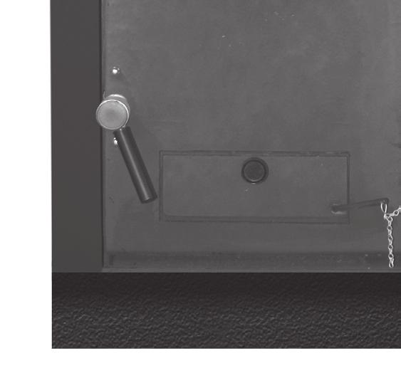
4 2. Installation 2.1. Boiler-room ventilation According to european safety regulations each boiler room should have supply-exhaust ventilation ensuring correct boiler operation and user s safety. Lack of ventilation or its obstruction is the main reason of incorrect boiler operation (i.e. boiler cannot reach set temperature).exhaust ventilation removes from boiler room used air and harmful gases. Boiler room with natural draught cannot have installed mechanical ventilation Supply air ventilation 1. Ventilating duct section should have at least 50% area of chimney s section and not less than 20 x 20 cm. Duct should be placed 1m above the floor. 2. Ventilating duct should have installed device for air flow control; device shouldn t limit duct section above 1/5.Ventilating duct should be made of non-inflammable material Exhaust ventilation 1. Exhaust duct should be made of bricks with section of at least 25% of chimney section not less 14 x 14 cm. Inlet hole cannot have any devices that reduce its section. Outlet hole should be placed close to the ceiling led out 1,5 m above the roof. Ventilating duct should be made of non-inflammable material. 2. Height of the boiler room min. 2,2 m Chimmey connection. Chimney ducts should be installed according to binding rules and norms in countries to which boilers are sold. Part of chimney system connection boiler with chimney is called flue. In order to lower flow resistance of exhaust gases this part should lead as a straight pipe with, if necessary, joints up to 45. Because of exhaust gases temperature ORLIGNO 100 s need to be connected to heat-resistant. 30 cm above the floor closing door should be installed with tight closing. Chimney section should be round or close to square shape because of low flow resistance. Minimal flue diameter should be 160 mm. Chimney should lead above the roof. Chimney outlet location is dependent on roof slope and its combustibility. 4
5 3. ORLIGNO 100 technical data Power wood Coke/pellets kw kw Boiler class acc. to EN /16 Efficiency coke pellets Max working pressure bar 3 Max temperature C 90 Min. temperature C 60 Water capacity ltr. 60 Weight kg 305 Loading chamber capacity ltr. 70 Length mm 1100 Width mm 675 Height mm 1220 Upper door dimensions mm 300x300 Water outlet inner thread inch 5/4 Return inner thread inch 5/4 Drain valve inner thread inch ½ Cooling coil inner thread inch ½ Min. cooling coil pressure bar 2 Flue diameter mm 160 Required chimney draft Pa 20 Max. moisture content: wood/pellets % 23/12 Exhaust gases temperature at nominal power C coke h 4,5 Burning period at nominal power wood h 2-2,5 % 76,5 86 Fuel parameters Water resistance wood/max length mm 500 pellets/ diameter mm 6-8 t=20 K mbar 0,8 t=10 K mbar 3,4 5
6 3.1. Dimensions 3.2. Boiler construction 6
7 3.3. Safety valve connection 7
8 ORLIGNO 100 is equipped with copper cooling coil mounted in boiler body, protecting boiler from overheating. To one of cooling coil tappings on right side of the boiler one should connect safety valve. When temperature increases above 95ºC safety valve opens and lets in cold water through cooling coil. Water from mains at 10ºC temperature cools down boiler, water from boiler is removed to drain. 8
9 4. Boiler startup Before first startup it is necessary to: - Check water level in installation, pressure in installation should be 2 bar. - Check fire-grate location (fire-grate gaps from bottom should be bigger than from top). - Draft regulator seal with oakum and mount, fit arm and block with screw. Startup: - Mount draft regulator horizontally, regulator set on 70 C. - Open flue flap. - Put on fire-grate papers and small wood pieces; open bottom door. - After lightning up put bigger wood logs and create ember layer (close bottom door and unscrew primary air flap opening in flap at least 2cm- regulation knob is located on bottom door. - After creating ember layer fully load boiler with wood or coke. Put wood logs along chamber. - Set chimney draft with flue flap - Connect draft regulator chain with primary air flap. Burn in boiler up to 70 C then set draft regulator on 70 C and shorten chain till primary air flap is barely opened. Draft regulator knob is for temperature change. Marking on regulator is every 10 C. ATTENTION! Before stoking boiler open slowly open upper door to suck out gases. ATTENTION! It is not allowed to open bottom door during boiler burning glow may fall out. SECONDARY AIR SETTINGS: - wood opening ½ - coke opening ¼. Troubleshooting Reason Activity Heat exchanger gets dirty to fast Use good quality wood, moisture content 18-23%. Smoke leakage Seal chimney pipe, open more flue flap, check chimney draft Too high temperature of exhaust gases Too short burning period Check fuel moisture content, cannot be too dry. Check secondary air settings. To high exhaust gases temperature: burning period depends on used fuel and heat demand 9
10 4.1. Boiler stoking In order to stoke boiler: 1. Close primary air flap. 2. Open completely flue flap. 3. Open slightly upper door in order to suck out gases through chimney. 4. Open completely upper door and stoke boiler. 5. Close upper door, return to previous setting of flue flap and primary air Tarring and condensation Lightning up in cold boiler may cause that water precipitated from fuel falls on boiler walls and runs down to ash chamber. That may look like boiler leakage. It is important to keep boiler temperature high enough at least 70 C. It is recommended to install four-way mixing valve which protects boiler from low temperature return below 50 C. Too humid wood also causes that boiler works on low temperatures, which leads to tarring. In order to avoid problem of tarring and condensation keep high boiler temperatures, boiler must be properly sized to heated space to avoid oversizing boiler then will work on low temperatures. 1. Boiler ORLIGNO Pressure vessel 3. Radiator 4. Safety valve- protection- from verheating 5. Four-way mixing valve 6. Safety group 10
11 5. Maintenance Advice: Clean boiler works efficiently. Boiler life is extended. - Fire-grate and ash clean/remove daily. - Boiler must be cool during this activities. - Open upper door and remove cleaning flap. - Check if heat exchanger surfaces are cleaned, clean with brush. - Remove ash from bottom chamber ( ashpan may be hot). - Fit cleaning flap. - Each 2-4 weeks clean boiler depending on burning intensity. 11
12 12
13 INSTRUCTION MANUAL Contents 1. Basic informations Construction description and burner application Fuel characteristics Transport and delivery specification Burner s technical data Package Location and package installation Rules, norms, recommendations Boiler room recommendation Ventilation Safe distance to inflammable substances Putting into operation Burner start Burner s assembly to ORLIGNO Adjustment of ORLIGNO 100 to work with pellet burner Tank assembly Before starting of the burner it is necessary Burner s maintenance Troubleshooting...27 II. Instrukcja regulatora Main functions of the controller Graphic display Service Simple menu Main menu Heating Hot domestic water Water tank Boiler Settings Burner Alarms Electric installation
14 1. Basic informations 1.1. Construction description and burner application Self- cleaning burner is a new look into the automatic burning of solid fuels in Europe pellets of 6-8 mm of diameter or as a option oats with maintaining low emissions, complying with European norms. Burner doesn t have any drawbacks of chute burners gravitational, in which ash and sinter have to be removed manually. Main burner advantage is its simple service: just fill in hopper with pellets and press START button. Reports are shown on big graphic display. Within few minutes burner will automatically select work parameters, maintain constant room temperature and hot utility water. Burner s features: - automatic burner s start - automatic modulation - flame control through photo-cell - low heat inertness during start and stop - low electric energy consumption - possibility to control 16 heating circuits (radiators and underfloor heating or hot utility water) option - control of burner s temperature - three phases of lightning up eliminate risk of explosions - AUTOSTART function after power failure memory of last settings - separation of primary and secondary air emissions on the same level as in gas and oil burners - efficiency > 94,5% - soot = 0 - self-cleaning function, automatically removes ash from the burner s grate - oats burner s construction enables to burn grain (oats) option 2 years of warranty for appliance durability enables to decrease exploitation and service costs. Burner s regulator can control: - boiler pump heating circuits (radiators or underfloor heating) controlled according to outside temperature - room s temperature 14
15 Useful functions of controller: You don t have to keep in mind about next boiler service it is shown on the display Statistics function enables to preview - minimal, maximal and average burner s power - fuel usage: minimal, maximal and average. Temperature s parameters are shown as a digits and charts on big graphic display 1.2. Fuel characteristics a) Pellet granulate made according to DIN granulate 5-8 mm - recommended calorific value kj/kg - ash content 1,5% - max moisture content 12% - density 1-1,4 kg/dm³ b) Oats - moisture content <15% ATTENTION! It is recommended to use fuel from reliable sources. Fuel should have appropriate humidity and low content of small fractions. It is necessary pay attention especially to mechanical pollution ( stones), which worsen burning process and may lead to burner s failure. Eko-Vimar Orlański sp. z.o.o. is not responsible for appliance failure or improper burning process when using inappropriate fuel. 15
16 1.3. Transport and delivery specification Burner during transport should be secured with straps against leaning and movement. Burner need to be stored in roofed and dry place. Burner is delivered in separate boxes wrapped in foil. Boxes contains: pellet tank with lid, fuel feeder, burner with controller and elastic feeding pipe. Before installation it is recommended to check delivery completeness and its condition. 16
17 2. Burner s technical data Parameter SI 16 kw Pellet power range kw 4 16 Oats power range* kw 3,6 14,4 Efficiency % >94,5 CO emission ppm <200 Weight kg 14 Feeder length standard m 1,3 1,6 Feeder length option m 2.0;2.5;3.0 Fuel pelety Fuel diameter mm 6 8 Fuel (option) humidity<15% owies Voltage V 230 Power consumption W 30 Protection level IP40 Tank dimensions mm 600x600x1400 Capacity L 305 ATTENTION! Producer reserves the right for construction and documentation changes in order to modernize the boiler. 1. Boiler 2. Burner 3. Fuel tank 4. Feed system Pic.1. Basic package elements. 17

18 1. Burner s body 2. Grate 3. Fan 4. Feeder casing ( worm+ igniter) 5. Drive plate 6. Plate for electric connections 7. Sealant 8. Motoreducer 9. Burner s casing Pic.2. Burner construction 3. Package Standard package: - b ur n e r - controller - fuel feeder - t ank - m anu al - 4 refractory bricks - Sensor sleeve ½ 18
19 4. Location and package installation 4.1. Rules, norms, recommendations Boiler room should comply with construction law valid in country where boiler is installed. Pic.3. Package layout. 19
20 4.2. Boiler room recommendation - Package ( boiler, burner, tank, feeder) should be placed in separate room, centrally to heated rooms - Front door should open outside and must be made of nonflammable materials, with 0,8 width - Floor should be made of nonflammable materials or covered with 0,7 mm steel plate at minimum 0,5 m distance to door edges. Boiler should be located on a nonflammable foundation, lifted 0,05 m above floor level - Boiler room should have artificial lightning but natural light is also recommended - Distance to walls in boiler room should allow for easy access to all sides of the boiler - Minimal distance from front side of the boiler to opposite wall should be 1m - Minimal height of the boiler room: at least 2,2 m; in existing building it is allowed 1,9 m with assured supply-exhaust ventilation. - It is forbidden to install boiler and burner in damp rooms or with elevated humidity. Corrosion process may in short time damage the boiler and burner Ventilation - Boiler room should have 200 cm² supply-air duct - Exhaust duct should have at least 14x14 cm section with inlet hole under boiler room ceiling that should lead above roof and be placed near chimney. - Ventilation ducts should be made of nonflammable materials. - It is forbidden to install mechanical ventilation ATTENTION! High risk of carbon monoxide poisoning exists if boiler is located in a room with insufficient access to fresh air Safe distance to inflammable substances - During installation and exploitation it is advisable to maintain safe distance of 200 mm from inflammable substances - For inflammable substances with C3 grade of combustibility which rapidly and easy burn (ex. paper, cardboard, wood, plastic) distance is minimum 400 mm; - If combustibility grade is unknown safe distance should be doubled. 20
21 Combustibility grade of building products A non-burning B - hard burning Building products sandstone, concrete, bricks, fire plaster, Mortar, tile, granite cement board, fiberglass, mineral insulation C1- hard burning beech tree, oak tree, plywood C2 middle burning pine, larch, spruce tree, cork, rubber floor cover C3 easy burning tarmac plywood, celuloids, polyurethane, Polystyrene, polyethylene, plastic User please remember: - Only adult person acquainted with this manual may operate the burner It is forbidden for kids to stay in close distance to burner without presence of adult person. - If inflammable gases penetrate boiler room during activities (varnishing, gluing) it is recommended to turn off the burner. - It is forbidden to use inflammable substances for lightning up the burner, burner will light up automatically. - High risk of fire exist when using open fire or inflammable substances close to installed boiler package. - Burner should be turned off during maintenance (position OFF. - Pay attention on hot burner s surfaces risk of burn. - It is forbidden to lay inflammable items on the burner or nearby. - All defects should be removed at once. - After heating season it is recommended to clean the burner and pellet tank thoroughly. - Oversee the burner during power failure - It is forbidden to manipulate with any electric parts or interfere in burner s construction. 21
22 5. Putting into operation 5.1. Burner start First startup of the burner must be done by authorized company trained by manufacturer with valid certificate of authorized serviceman issued by Eko-Vimar Orlanski ltd Burner s assembly to ORLIGNO Remove the screws (1) fastened to burner s casing (pic.4) and take off casing (2) 2. Take off ORLIGNO 100 bottom door 3. Fix adapter (3) in bottom s door place (pic.5) 4. Fix burner (4) in adapter (3) screwing it with two bolts (5) 5. Mount burner s casing (2) with two screws (1) 6. Slide feeder s pipe (6) in to fixing pipe (7) (pic.6) 7. Fit flexible pipe (8) on feeder s pipe (6) and secure with band clip (9) 8. Fit flexible pipe (8) on burner s pipe (10) and secure with band clip (9) 5.3. Adjustment of ORLIGNO 100 to work with pellet burner 1. Remove iron-cast grate from boiler. 2. Place two refractory bricks on each of two supports above support for iron-cast grate. Pic.4. Disassembly of burner s casing. 22
23 Pic.5. Burner assembly. Pic.6. Feeder assembly 23
24 5.4. Tank assembly 24
25 5.5. Before starting of the burner it is necessary: 1. Check installation condition. 2. Fill in pellet to the tank, cover with lid 3. Check if fuel contains any unwanted elements ( rocks, metal elements) 4. Screw in sensor s sleeve in one of two probes on the right side of boiler behind safety coil 5. Put the boiler sensor in to the sleeve Pellet* 30% of power 100% of power Feed time 1,5 5 Max air 8 13 OATS** Feed time 2 7 Max air Feed fuel from tank till it show up in flexible pipe. 9. Turn off fuel feed and hold ON button. 10. When changing fuel ex. on oats; it is necessary: - turn off boiler - wait till boiler cool down - remove pellet grate and clean surface - put oats grate - set feed time and max air amount acc. to chart 11. Burner maintenance after heating season: - turn off and disconnect from power supply - clean thoroughly - remove pellet from tank 25
26 6. Burner s maintenance ATTENTION! It is necessary to put out, cool down and disconnect burner from power supply when servicing. Pay attention on hot burner s surfaces risk of burn. In order to keep high efficiency of burner it is recommended to clean and service it systematically. Remove soot and ash from burner s grate. ATTENTION! Much more ash is created during oats burning than pellets. Cleaning activities: 1. Turn off the boiler (wait till burner completely put out), disconnect boiler from power supply and wait till boiler cool down. 2. Disconnect burner form boiler and power supply. 3. Remove grate from burner and clean it ( check permeability of air holes) Clean burner s casing (pic.7) Pic.7. Burner maintenance. 26
27 7. Troubleshooting Type of defect Possible cause of defect Suggested repair One of controller s button doesn t work Automatic lightning up Doesn t work Smoke from door or burner Display malfunction Wrong connection of igniter or photo-cell Clogged outlet hole of hot air Very damp fuel Damaged igniter Damaged photo-cell Lack of chimney draft Clogged chimney Clogged heat exchanger Damaged sealant (rope) Display repair Check plug and wires connections of igniter and photo-cell Clean heater hole Change or dry fuel Replace igniter Replace photo-cell Clean heat exchanger Replace sealant (rope) Water in boiler Lack of chimney draft Improper chimney installation Very damp fuel Change or dry fuel Leaky heat exchanger To check heat exchanger, turn off boiler on 8 hours, remove water, when water is still in boiler call service Boiler cannot reach Improperly selected boiler for Check if boiler is properly selected set temperature heating space Wrongly located sensor of return Check sensor location water Sensor malfunction Check sensors Set low boiler power Check feed time and fan power 27
 Buttons (2.1.2) Status diode (2.")


28 8. Main functions of the controller Front panel Graphic display (2.1.3) Buttons (2.1.2) Status diode (2.1.1) 8.2. Status diode Lightning description Green- continuous light Green pulsate Orange continuous light Orange pulsate Red continuous light Red pulsate Meaning Controller off Controller on, burner off Controller on, burner on Burner work Alarm to confirm Alarm active 28

29 8.3. Buttons Button Return, Esc Function Return in menu to previous level, cancellation of parameter s change. After pressing button > 3 sec change of controller s status ON/OFF Menu moving, decrease parameter s value On main display entering to simple menu Arrow down Shows navigational informations and description of parameters Info Menu moving, increase parameter s value On main display entering to simple menu Arrow up Enter the menu. Confirmation of edited parameter Alarm confirmation Enter 9. Graphic display 9.1. Graphic display grate status weekday time set temperature actual temperature object symbol (boiler) processor s temperature number of unconfirmed alarms heating program ( time program, permanent, off) h.d.w. program (time program, permanent, off) grate program (OFF/ON) controller s status (OFF/ON) 29
30 9.2. Grate statuses Status OFF Cleaning Lightning up Kindling Power 1 Power 2 Modulation Extinguishing Stop Description Burner doesn t work. Work approval off. Burner cleaning with strong stream of air. Fuel lightning up. Initial fuel feeding, Heater and fan are on. After flame detection, additional fuel feeding and fan power increase for better grate kindling. Burner works with first power. Burner works with second power. Burner works with modulated power. Grate extinguishing. Feeder and fan work till flame die out. Burner doesn t work. Required boiler s temperature reached. 10. Service Menu navigation Controller contains two types of menu: simple and main menu. Simple menu enables to access basic functions of the controller. To enter simple menu press button arrow up or arrow down on main display. Simple menu description chapter 4. Main menu enables to access all functions of the controller ( monitoring of status, changes and service settings ). To enter main menu press Enter on main display. Main menu description chapter 5. ATTENTION! Service menu is only for qualified staff. Any settings changes may lead to incorrect system operation Start of the controller ON In order to start the controller (mode ON) press for 3 sec Return, Esc on main display, when it is in OFF mode. 30
, it s not advisable to disrupt this process.")
31 10.3. Shutdown of the controller OFF In order to turn the controller off (mode OFF) press for 3 sec Return, Esc on main display, when it is in ON mode. ATTENTION! After controller shutdown depending on its previous status, burner may still work (extinguishing ), it s not advisable to disrupt this process. If controller will be disconnected from main power, please wait till burner status is on OFF mode Time programs Controller is equipped with clock and calendar. Thanks to that it is possible to program work of individual parts of heating system depending on current time and weekday. Date and time aren t deleted during power outage because controller contains battery, which needs to be replaced every 2 years. Programming takes place in menu of given heating circuit ( ex. hot domestic water, heating, water tank) and for each element proceeds in the same way. Weekday choice. After entering in menu Time program, weekday pulsates, with arrow buttons choose day for setting or just to check program settings. Programming. After choosing weekday and confirming with Enter button; current programmed hour starts to pulsate, next to displayed hour, icon with chosen time zone is shown (sun symbol stands for comfort temperature, moon symbol economic temperature). To move to next hour press arrow down button ( comfort temperature) or arrow up (economic temperature). If all day is programmed press enter. After confirmation of changes (or cancellation) weekday starts to pulsate. grate status day arrow up set comfort temperature arrow down set economic temperature chosen temperature (economic) actual set temperature Economic temperature 00:00-6:00 Comfort temperature 6:00-9:00 Economic temperature 9:00-18:00 Comfort temperature 18:00-24:00 31
32 ATTENTION! Values of economic and comfort temperatures are set in SETTINGS menu and may differ for each of the heating circuits. In order to activate time program activate it in SETTINGS menu Service password Access to service parameters is protected with password. After writing correct password access is cleared. Access is denied after 10 minutes without pressing the buttons. Service password: it is a set temperature in BOILER/SETTINGS menu and 3 letters EST Example: If set temperature in BOILER/SETTINGS menu is 60 C then password is: 60EST. ATTENTION! Service menu is only for qualified staff. Any settings changes may lead to incorrect system operation. 32
 and programmed temperature (small type).")

33 11. Simple menu Simple menu s displays Display Description Shows current boiler temperature (large type) and programmed temperature (small type). After pressing Enter button: set desired boiler s temperature Shows current h.d.w. temperature (large type) and programmed temperature (small type). After pressing Enter button: set desired h.d.w. temperature Heats once h.d.w. till reaching comfort temperature no matter of program. H.d.w. program no. 1: a. time program according to programmed time- intervals b. permanent no matter of time-intervals comfort temperature is kept c. off heating is turned off. 33


34 Shows current room temperature in room no.1 (large type) and set value (small type). After pressing Enter, set desired room temperature Circuit heating program no. 1: a. time program according to programmed time- intervals b. permanent no matter of time-intervals comfort temperature is kept c. off heating is turned off Burner work: ON/OFF. When burner is OFF, controller controls heating system, but doesn t start the burner. Manual start of feeder from pellet tank. Function useful after fuel runs out. After filling the tank with fuel activate FEED THE FUEL function, till the moment when fuel will be on the burner. 34
35 12. Main menu 13 Heating strona H.d.w page Water tank page Boiler page Settings page Burner page Alarms page 43 35

 Programmed temperature at source ( C) Valve")
36 13. Heating Circuit selection Enables to choose number of heating system circuit. Selection of circuit: arrow down/up Status Enables to monitor status of central heating. Circuit number Name of circuit Measured temperature/ programmed in room Measured temperature/ programmed in radiators Outside measured temperature Valve work time (sec) Programmed temperature at source ( C) Valve work signalling Pump work signalling 36
37 13.3. Settings Description of functions in submenu SETTINGS. Function Comfort temperature Program Economic temperature Description Programmed temperature in room during heating. Programs: a. time program according to programmed time- intervals b. permanent no matter of time-intervals comfort temperature is kept c. off heating is turned off d. economic during all period economic temperature in room is kept Programmed temperature in room after heating period Time program It is for time program configuration that controls central heating. Settings description of time program can be found in chapter Service ATTENTION! Service menu is only for qualified staff. Any settings changes may lead to incorrect system operation. Description of functions in submenu SERVICE. Function Temp. MIN pump comf. Temp. MIN pump. econ. Source Max. temperature Mixing valve time H.d.w. priority Pump test Mixing valve test Circuit name Description Minimal calculated central heating temperature, at which pump is ON during comfort period. Minimal calculated central heating temperature, at which pump is on during economic period Determines source of energy for central heating Maximal calculated temperature for central heating Time when mixing valve is fully opened H.d.w. priority for given central heating circuit; during h.d.w. heating, central heating pump doesn t work Starts circulation pump regardless of outside conditions. Starts mixing valve actuator regardless of outside conditions. Gives the name for central heating circuit. 37


38 14. Hot domestic water Circuit selection Enables to choose number for h.d.w. circuit Status Enables to monitor status of h.d.w. Circuit number Circuit name Measured temperature/ programmed for h.d.w. Source programmed temperature ( C) Pump work signalling 38
39 14.3. Settings Description of functions in submenu SETTINGS Function Comfort temperature Program Heat now Hysteresis Description Programmed temperature of h.d.w. during heating period Programs: a. time program according to programmed time- intervals b. permanent no matter of time-intervals comfort temperature is kept c. off heating is turned off Heats once h.d.w. up to comfort temperature regardless of program Decrease of temperature value for h.d.w. Economic temperature Programmed h.d.w. temperature after heating period Time program It is for time program configuration of h.d.w. Settings description of time program can be found in chapter Service ATTENTION! Service menu is only for qualified staff. Any settings changes may lead to incorrect system operation. Description of functions in submenu SERVICE: Function Source delta Source Max. temperature Delta MIN temp. Pump test Circuit name Description Source temperature increase in relation to programmed h.d.w temperature during heating. Determines source of energy for h.d.w. Maximal h.d.w. temperature Minimal temperature difference between source and h.d.w, at which pumps work Starts pump regardless of other conditions. Gives the name for h.d.w. circuit 39

40 15. Water tank Service ATTENTION! Service menu is only for qualified staff. Any settings changes may lead to incorrect system operation. 16. Boiler Status Boiler work statistics during last 24h. Chart shows boiler s temperature and burner power Settings Description of functions in submenu SETTINGS. Function Programmed boiler s temperature Description Heat medium temperature in the boiler kept by the controller Service ATTENTION! Service menu is only for qualified staff. Any settings changes may lead to incorrect system operation. 40

41 Description of functions in submenu SERVICE: Function Pumps MIN temp Work mode Hysteresis Description Temperature above which controller may turn on the pumps Boiler s work mode: a. auto temperature set automatically b. continuous temperature is kept continuously Temperature s value that needs to decrease to start the burner. 17. Settings Date and time Enables to set the date and controller s time Language Enables to choose controller s language in menu Restore factory settings Selecting this option enables to cancel all current controller s settings and restore factory settings. 18. Burner Status Animation showing work of burner s appliances. 41
42 18.2. Settings Description of functions in submenu SETTINGS. Function Feed the fuel Burner s work Type of fuel Description Starts feeder regardless of other functions. Burner s work approval. Determines type of burned fuel Service ATTENTION! Service menu is only for qualified staff. Any settings changes may lead to incorrect system operation. Function Description of functions in submenu SERVICE Air MIN Minimal air amount during modulation or at power no. 1 Air MAX Maximal air amount during modulation or at power no. 2 Feeding MAX MIN power MAX power Modulation type Photo threshold Test of igniter Test of burner s feeder Test of fuel s feeder Test of fan Minimal burner s power during modulation. Maximal burner s power during modulation. Maximal burner power during modulation. Method of burner s work, modulated power or 2 levels of power Brightness in burner, above which controller recognizes flame Starts igniter for test. Starts feeder for test. Starts feeder for test. Starts fan for test. 42
43 19. Alarms Menu contains history of maximum 20 alarms, that occured during controller s work. Meanings of code alarms is shown below: Alarm codes and their meaning. Code Short description Description 1 Processor s overheating Controller s processor has been overheated. Improper controller placement may be one of the reasons. 2 Lack of flame/fuel Controller detected lack of flame in burner. Lack of fuel or flame gone out may be one of the reasons. 3 Burner s overheating Burner s temperature has exceeded maximum value 4 Boiler s sensor short circuit Controller detected short circuit. Damaged sensor or connecting wire may be one of the reasons. 5 Boiler s sensor break Controller detected gape of boiler sensor. Damaged sensor or conecting wire may be one of the reasons. 6 Burner s sensor short circuit Controller detected gape of sensor. Damaged sensor or connecting wire may be one of the reasons. 7 Gape of burner s sensor Controller detected gape of sensor. Damaged sensor or connecting wire may be one of the reasons 8 Boiler s overheating Boiler s temperature has exceeded maximum value 9 Processor reset Possible controller s damage! Lack of power supply 43
44 20. Electric installation Overall requirements Before use of this controller; it is necessary to thoroughly read instruction manual. Person responsible for controller s installation should have technical experience. Connections made of copper should be adjusted to operate at temperatures of 75 C. All electric connections should comply with electric scheme enclosed in this manual and national or local rules concerning electric installations ATTENTION! Appliance should be connected to separate electric circuit equipped with properly selected RCD (residual current device) and MCB ( miniature circuit breaker) Location Appliance is intended for use in confined premises. Assembly location must be free from dampness and inflammable, fumes that cause corrosion. Appliance assembly cannot be done close to any high-power, appliances, industrial equipment or welding equipment. Ambient temperature around assembly place cannot exceed 60 C and should not be lower than 0 C. Humidity should be in range 5-95% Connection It is necessary to connect to boiler sensor and other executiue elements if needed. Picture shows connection diagram of appliances table shows description of inputs and outputs. ATTENTION! It is not allowed to connect (PE) safety wire with zero(n). 44
45 ATTENTION! Connection works should be made when controller is disconnected from power. Only authorized person is allowed to do electrical connections with necessary qualifications. BACK VIEW OF CONTROLLER FILTER Output description Foto Tkotła Tpalnik Tc.w.u. Tpokój GND Pcwu Zapalarka Pco Dmuchawa Pod.zas. Pod.pal N N1 PE Description Brightness sensor in burner Boiler sensor Burner sensor Hot domestic water sensor Room sensor Ground for sensor connection Hot domestic water pump Burner's igniter Central heating pump Burner's fan Pellet tank feeder Burner's feeder Neutral constant Neutral separable Protective 45
46 20.4. Technical data PARAMETER VALUE Power supply ~230V/50Hz ±10% Power consumpion <6VA Outputs capacity: Central heating pump 100W Hot domestic water pump 100W Igniter 400W Fan 150W Burner's feeder 150W Pellet tank feeder 150W Measurement accuracy Sensors Outside temperature Humidity Software class ±4ºC NTC 10kΩ B 25/85 =3877K±0,75% VISHAY BCcomponents 0-60ºC 5-95% without condensation A 46
47 47


48 EKO-VIMAR ORLAŃSKI Sp. z o.o Otmuchów, ul. Nyska 17b POLSKA / woj. opolskie T , F , E biuro@orlanski.pl
INSTRUCTION MANUAL & SERVICE MANUAL ORLIGNO 400
 INSTRUCTION MANUAL & SERVICE MANUAL ORLIGNO 400 ISO 14001 ISO 9001 Content 1. Delivery... 3 2. Boiler view after assembly...4 3. Pellet tank assembly...5 4. Dimensions...6 4.1. ORLIGNO 400 16kW...6 4.2.
INSTRUCTION MANUAL & SERVICE MANUAL ORLIGNO 500
 INSTRUCTION MANUAL & SERVICE MANUAL ORLIGNO 500 MANUAL INSTRUCTION CONTENTS 1. Boiler application...3 2. Description of the controller...3 2.1. Lightning up...........................................................
ISO 9001 TUV CERT CE
 ISO 9001 TUV CERT CE INSTRUCTION MANUAL CONTENT 2 1. Boiler application 2. Principle of work 3. Description of the controller 3.1. Front panel of EKOSTER 2 3.2. Main functions of EKOSTER 2 4. Gasification
INSTRUCTION MANUAL & SERVICE MANUAL ORLIGNO 400
 INSTRUCTION MANUAL & SERVICE MANUAL ORLIGNO 400 Content 1. Delivery......................................................................... 3 2. Installation and assembly.........................................................
INSTRUCTION MANUAL & SERVICE MANUAL ORLIGNO 400
 INSTRUCTION MANUAL & SERVICE MANUAL ORLIGNO 400 Content 1. Delivery...3 2. Installation and assembly...3 3. Boiler view after assembly...6 4. Pellet tank assembly...7 5. Dimensions...8 5.2. ORLIGNO 400
INSTRUCTION MANUAL & SERVICE MANUAL ORLAN 96 SUPER ORLAN 130 SUPER
 INSTRUCTION MANUAL & SERVICE MANUAL ORLAN 96 SUPER ORLAN 130 SUPER INSTRUCTION MANUAL Content 1. Boiler application...3 2. Principle of work...3 3. Description of the controller...4 3.1. Front panel of
INSTRUCTION MANUAL & SERVICE MANUAL ORLIGNO 200
 INSTRUCTION MANUAL & SERVICE MANUAL ORLIGNO 200 CE INSTRUCTION MANUAL Content 1. Boiler application...3 2. Principle of work...3 3. Description of the controller...4 3.1. Front panel of EKOSTER 2...4 3.2.
PELLETS BURNER 15-60kW MOC
 PELLETS BURNER 15-60kW MOC. Please read those documentation before first start up the unit. Improper burner start may lead to its damage and may create a danger for end user! Table of Contents: 1. Admission
natural warmth of the house A compact boiler designed to combust ecological fuel- pellet ORLIGNO 500 Compliant with EN norm
 natural warmth of the house A compact boiler designed to combust ecological fuel- pellet ORLIGNO 500 Compliant with EN 330-5 norm Biomass - the curse of energetics or the only fuel of the future? The real
Operating manual. Pellet boiler. Orlan Pellet ISO 9001
 Operating manual Pellet boiler Orlan Pellet ISO 9001 Contens 1. Boiler s use...................................................................... 3 2. Boiler s way of working...........................................................
Eco Angus Wood Pellet Boilers
 Eco Angus Wood Pellet Boilers ISO 9001 ISO 14001 1 Contents 3 Our product philosophy 3 Our approach 3 Manufacturing credentials 4 Orligno 400 4 Boiler construction 5 Boiler description 5 Burner 6 Technical
INSTRUCTIONS FOR USE OF COMBINED BOILER INTENDED FOR COMBUSTION OF BOTH PELLETS AND SOLID FUEL ABC COMBO
 INSTRUCTIONS FOR USE OF COMBINED BOILER INTENDED FOR COMBUSTION OF BOTH PELLETS AND SOLID FUEL ABC COMBO .Technical specifications Boiler power DESCRIPTION Water content in a boiler Required draft Supply
BOILER CONTROLLER COMPACT
 BOILER CONTROLLER COMPACT page 2 Index Index 1 General information 5 1.1 Introduction 5 1.2 Features 5 1.3 Safety precautions 7 1.4 Disposal of old equipment 8 2 Connecting to the system 9 2.1 General
PELLET BURNER PV 350
 PELLET BURNER PV 350 INSTRUCTION MANUAL v1.1 1 PRODUCT DESCRIPTION...3 2 SAFETY RULES...3 3 WARNINGS...4 4 INSTALLATION INSTRUCTIONS...5 4.1 BOILER REQUIREMENTS...5 4.2 PELLET CONTAINER...6 4.3 INSTALLATION
Wood gasification process...3. Wood as a fuel...3. Boiler construction - its elements...4
 Wood gasification process... Wood as a fuel... Boiler construction - its elements...4 Boiler construction - materials...4 EKO advantages...4 Boiler construction - schematics... Boiler dimensions... Boiler
PER-EKO type KSW & KSW PLUS Instruction Manual
 TABLE OF CONTENTS INTRODUCTION..... 3 1. GENERAL INFORMATION..... 3 1.1. Application.. 3 1.2. Fuel..... 3 1.3. Dimensions & technical parameters........ 4 2. BOILER TECHNICAL SPECIFICATION...... 4 2.1.
Figure 1 Solid fuel cook-stove KMŠ 70 and KVŠ 90H
 Figure 1 Solid fuel cook-stove KMŠ 70 and KVŠ 90H 1. 2. 3. 4. 5. 6. 7. Fire box door Ash pan door Air inlet control Fuel drawer Side flue gas connector Oven door with double glass Protective cover for
Operating manual. Wood gasification boiler at kw. Orlan STANDARD, SUPER IRL
 Operating manual Wood gasification boiler at 18-80 kw Orlan STANDARD, SUPER IRL ISO 14001 ISO 9001 Contents 1. Boiler s use...3 2. Procedure rule...4 3. Installation...4 3.1. Diagram of chimney choice
PELMAX HEATING BOILER FOR SOLID FUEL
 PELMAX HEATING BOILER FOR SOLID FUEL INSTALLATION, SERVICE AND MAINTENANCE MANUAL OF THE BOILER Member of the NIBE Group 21683 Issue 06.2012 Changes reserved Installation, service and maintenance manual
Solid fuel hot water boiler TKH KW INSTRUCTIONS MANUAL for usage and maintenance
 Solid fuel hot water boiler TKH 250-400 KW INSTRUCTIONS MANUAL for usage and maintenance Prhovacka bb 22310 Simanovci, Srbija Tel/Fax. +381 22 480404 +381 63 259422 oce@termomont.rs www.termomont.rs April
USER MANUAL 9kW LILLY PELLET STOVE
 USER MANUAL 9kW LILLY PELLET STOVE Table of Contents.Overview of Stove Parts... 2.Technical Characteristics... 3 3.Important Information... 4 4.Pellet Specification...5 5.Technology... 6 6.Installation...
Operation and maintenance manual for the. KSP Spark. series boilers equipped with feeders
 Operation and maintenance manual for the KSP Spark series boilers equipped with feeders Thank you for purchasing PEREKO heating boiler. This documentation applies to the KSP Pelet boilers with fuel feeder
INSTRUCTIONS FOR INSTALLATION AND MANUAL Solid fuel stove for central heating THERMO IN
 INSTRUCTIONS FOR INSTALLATION AND MANUAL Solid fuel stove for central heating THERMO IN To respected customer, We are very pleased for your trust and your decision to buy our product. You made a good choice,
TECHNICAL INSTRUCTIONS USE AND MAINTENANCE
 TECHNICAL INSTRUCTIONS USE AND MAINTENANCE Cm Pelet-set For boilers CentroPlus 25/35 and CentroPlus-B 25/35 (solid fuel and wood pellets fuel firing) TUPSCP-K-11-2016-ENG CONTENTS 1.Introduction 2. Status
OPERATION MANUAL RK-2006LPP AUGER FITTED SOLID FUEL BOILER TEMPERATURE CONTROLLER. Version DC19
 OPERATION MANUAL RK-2006LPP AUGER FITTED SOLID FUEL BOILER TEMPERATURE CONTROLLER Version DC19 1. Application. Controller RK-2006LPP is designed for temperature control of solid fuel fired water boilers
SWEBO Bioenergy Manual pellet burner PB50 Rev no. Date Page PBM1: (37) Installation and maintenance instructions
 Installation and maintenance instructions") PBM1:12 2008-10-16 1 (37) Installation and maintenance instructions PBM1:12 2008-10-16 2 (37) TABLE OF CONTENTS 1 GENERAL INFORMATION... 5 1.1 PELLET STORAGE... 6 1.2 CONSTRUCTION AND FUNCTION... 7 1.2.1
PBM1:12 2008-10-16 1 (37) Installation and maintenance instructions PBM1:12 2008-10-16 2 (37) TABLE OF CONTENTS 1 GENERAL INFORMATION... 5 1.1 PELLET STORAGE... 6 1.2 CONSTRUCTION AND FUNCTION... 7 1.2.1
SAUNA HEATER INSTALLATION AND OPERATING MANUAL
 SAUNA HEATER INSTALLATION AND OPERATING MANUAL Type Stoveman 13 Models 13R; 13R-M; 13; 13-M; 13R-LS; 13R-M-LS; 13-M-LS; 13-LS Heating output in the sauna room 15.4 kw Sauna room cubage 6-13 m³ Fuel Wood
INSTRUCTIONS FOR INSTALLATION, SETTING AND USE
 BUILT-IN FIREPLACE INSTRUCTIONS FOR INSTALLATION, SETTING AND USE 1. BUILT-IN FIREPLACE SPECIFICATION - WIDE 730 mm - DEPTH 426 mm - HEIGHT 543 mm - NOMINAL POWER 11 KW - CHIMNEY POT DIAMETER Ø 180 mm
TECHNICAL AND OPERATIONAL DOCUMENTATION
 METAL AND BOILER FACTORY 28-100 Busko-Zdrój, Owczary, ul Przemysłowa 3 Tel No +4841 378 46 19, fax +4841 370 83 10 TECHNICAL AND OPERATIONAL DOCUMENTATION SAS MULTI FLAME BURNER ADAPTED FOR BURNING OF
Combined boiler. for solid fuel and pellets
 Combined boiler ATTACK WOOD&PELLET for solid fuel and pellets W W W. A T T A C K. S K MODEL STRUC TURE OF THE AT TACK BOILERS THE NEW LINE OF ATTACK BOILERS FOR WOOD AND PELLETS 3000 000 6000 4 ATTACK
Heating, Air Conditioning, Ventilation. Отопление-Кондиционеры-Вентиляция. MTM 8-30 kw UNIVERSAL OIL HEATER OPERATING MANUAL
 Heating, Air Conditioning, Ventilation Отопление-Кондиционеры-Вентиляция MTM 8-30 kw UNIVERSAL OIL HEATER OPERATING MANUAL 1. Usage MTM 8-30 universal oil heater is designed for heating commercial rooms
Pellet burner PELETIX II+ Operating and assembly manual VER_EN_2.0_2015
 Pellet burner EN PELETIX II+ Operating and assembly manual VER_EN_2.0_2015 5. Installation... 8 Table of content 1. Introduction... 3 2. Safety... 3 2.1. Regulations and standards... 3 2.2. Precautions
SOLID FUEL HEATING UNIT TYPES NPS 35 AND NPS 70 ORIGINAL INSTRUCTION MANUAL
 SOLID FUEL HEATING UNIT TYPES NPS 35 AND NPS 70 ORIGINAL INSTRUCTION MANUAL 1. General information The Original Instruction Manual constitutes an integral and material part of the product, and is to be
INSTRUCTION MANUAL & SERVICE MANUAL. ORLAN SUPER kw. Orlan
 INSTRUCTION MANUAL & SERVICE MANUAL ORLAN SUPER 18-80 kw Orlan ISO 14001 ISO 9001 CE Contents 1. Boiler s use...3 2. Procedure rule...4 3. Installation...4 3.1. Diagram of chimney choice according to the
MANUAL FOR USE AND INSTALATION STOVE MODELS: D11-D17
 MANUAL FOR USE AND INSTALATION STOVE MODELS: D11-D17 CE Tested by the DIN EN 13240 15a B-VG Austria Type 1 Color Emajl d.o.o. Alaginci 87 a 34000 Požega Croatia www.color.hr team@color.hr 1 Attention!
Dear Users of Mini Bio Boiler. Before installing and starting up the boiler you should: Basic principles for the safe operation of the boiler!
 2 Dear user of KOSTRZEWA s equipment!! We want to take this opportunity to thank you for choosing our equipment. You have selected the highest quality product of the company known and appreciated throughout
USE AND MAINTENANCE. Cm Pelet-set (60-90 kw) TECHNICAL INSTRUCTIONS
 TECHNICAL INSTRUCTIONS") CENTROMETAL d.o.o. Glavna 12 40306 Macinec Croatia tel: +385 40 372 600; fax : +385 40 372 611 TECHNICAL INSTRUCTIONS USE AND MAINTENANCE Cm Pelet-set (60-90 kw) For boilers: EKO-CK P 70-110 TUPS-90K-09-2015-E-N-eng
CENTROMETAL d.o.o. Glavna 12 40306 Macinec Croatia tel: +385 40 372 600; fax : +385 40 372 611 TECHNICAL INSTRUCTIONS USE AND MAINTENANCE Cm Pelet-set (60-90 kw) For boilers: EKO-CK P 70-110 TUPS-90K-09-2015-E-N-eng
INSTALLATION AND MAINTENANCE INSTRUCTIONS PELLUX PELLUX 100 H AP
 MOS GB 1248-1 231259 INSTALLATION AND MAINTENANCE INSTRUCTIONS H AP Table of Contents For Home Owners General System description Area of use 3 Product description 3 Heating 3 Hot water heating 3 System
ecomax 200 W Boiler regulator FOR SOLID FUEL BOILERS WITH A FAN OPERATION AND MAINTENANCE MANUAL ISSUE:
 Boiler regulator ecomax 200 W FOR SOLID FUEL BOILERS WITH A FAN OPERATION AND MAINTENANCE MANUAL ISSUE: 1.3 APPLICABLE TO SOFTWARE 10.034 10.035 10.036 2010-04-14 TABLE OF CONTENTS 1 Safety... 4 2 General
Electronic Pellet Burner Controller NPBC-V3M
 Electronic Pellet Burner Controller NPBC-V3M SOFTWARE VERSION 3.3a/3.2 page of 27 CHANGES IN THE USER MANUAL OR IN THE CONTROLLER'S SOFTWARE Version of the user manual Changes Page 2.2. The software version
INSTALLATION AND OPERATING INSTRUCTIONS. Ariterm 60+
 INSTALLATION AND OPERATING INSTRUCTIONS Ariterm 60+ CONTENTS General.... 2 Installation.... 4-5 Installation of temperature limit valve... 6 Measurements and connections... 7 Technical specifications and
OPERATION AND MAINTENANCE MANUAL and WARRANTY
 Orte Power Pellet Air Heater CONTENTS I. Operating and maintenance manual OPERATION AND MAINTENANCE MANUAL and WARRANTY Device version: 03/2012 Document version: 36/2016/JK Orte Polska Sp. z o.o. Groblowa
USE AND MAINTENANCE. Cm Pelet-set TECHNICAL INSTRUCTIONS. (14-35 kw) For boilers: EKO-CK P (EKO-CK 20-40) EKO-CKB P (EKO-CKB 20-40)
 For boilers: EKO-CK P (EKO-CK 20-40) EKO-CKB P (EKO-CKB 20-40)") TECHNICAL INSTRUCTIONS USE AND MAINTENANCE Cm Pelet-set (14-35 kw) For boilers: EKO-CK P 20-40 (EKO-CK 20-40) EKO-CKB P 20-40 (EKO-CKB 20-40) TUPS-K-02-2011-E-N-ENG CONTENTS 1. Introduction....... 2. Status
TECHNICAL INSTRUCTIONS USE AND MAINTENANCE Cm Pelet-set (14-35 kw) For boilers: EKO-CK P 20-40 (EKO-CK 20-40) EKO-CKB P 20-40 (EKO-CKB 20-40) TUPS-K-02-2011-E-N-ENG CONTENTS 1. Introduction....... 2. Status
PELLUX 100/20 PELLUX 100/30
 24/02/2015 24148 INSTALLATION & OPERATING MANUAL PELLUX 100/20 PELLUX 100/30 AP H To Users Information for the User Information for the User We recommend the following steps after the consumption of 300
Rocket heater GAMERA
 Rocket heater GAMERA High efficiency heater on hard fuel Manufacturer: AGNON Ltd., Bulgaria Hissarya, 4 Han Kubrat STR. +359 885 525 464 WWW.GAMERA.EU ROCKETGAMERA@GMAIL.COM ATTENTION! Read the following
TECHNICAL MANUAL. Multifuel Stove Model EW1MF. To be retained by the user for future reference. Serial Number. Document EW1MF 0209
 TECHNICAL MANUAL Multifuel Stove Model EW1MF To be retained by the user for future reference Serial Number. Document EW1MF 0209 Thank you for purchasing an ACR Heat Products stove. The Earlswood stove
PELLUX INSTALLATION AND MAINTENANCE INSTRUCTIONS PELLUX 100 H AP
 MOS GB 1411-1 331139 INSTALLATION AND MAINTENANCE INSTRUCTIONS H AP Table of Contents For Home Owners General System description Area of use 3 Product description 3 Heating 3 Hot water heating 3 System
Operation and maintenance manual. for the boilers with feeder: KSR Beta and KSR Beta Plus
 Operation and maintenance manual for the boilers with feeder: KSR Beta and KSR Beta Plus Thank you for purchasing PEREKO boiler. This technical documentation applies to feeder boilers from the KSR Beta,
Operation and maintenance manual for the boilers with feeder. Q-Per
 Operation and maintenance manual for the boilers with feeder Q-Per Thank you for purchasing PEREKO boiler. This technical documentation applies to feeder boilers from the Q-PER series and contains all
BIOMASS BOILER ATTACK PELLET 30 AUTOMATIC PLUS
 BIOMASS BOILER ATTACK PELLET 30 AUTOMATIC PLUS W W W. A T T A C K. S K MODEL STRUC TURE OF THE AT TACK BOILERS THE NEW LINE OF ATTACK BOILERS FOR WOOD AND PELLETS 3000 000 6000 4 ATTACK FD PELLET yattack
Cm Pelet-set (60-90 kw)
") CENTROMETAL d.o.o. Glavna 12 40306 Macinec Croatia tel: +385 40 372 600; fax : +385 40 372 611 TECHNICAL INSTRUCTIONS FOR THE COMMISSIONING AND ADJUSTMENT Cm Pelet-set (60-90 kw) For boilers: EKO-CK P
CENTROMETAL d.o.o. Glavna 12 40306 Macinec Croatia tel: +385 40 372 600; fax : +385 40 372 611 TECHNICAL INSTRUCTIONS FOR THE COMMISSIONING AND ADJUSTMENT Cm Pelet-set (60-90 kw) For boilers: EKO-CK P
BIX B-One 100 kw INSTALLATION GUIDE
 BIX B-One 100 kw INSTALLATION GUIDE Dear Customer, We thank you for choosing our product. The Bix B-One 100 Kw is a burner of advanced concept and technology, with a high reliability and construction quality.
Main components. Buying all components from same manufacturer or reseller it guarantees better compatible and service if something happens
 Main components The bigger the need of heat output is. the bigger the components (storage. boiler. chimney etc.) In private houses the output need of the boiler is about 25 40 kw and in farms from 60 kw-
REV.01 /
 REV.01 / 2012 123794 CAUTION! Observe the safety instructions of this installation and maintenance manual before placing the boiler in operation. If an unqualified person carries out installation, adjustment,
INSTALLATION, OPERATION AND MAINTENANCE. Ariterm Vedo
 INSTALLATION, OPERATION AND MAINTENANCE Ariterm Vedo CONTENTS General...3 Installation...4-5 Laddomat 21 Connection diagram...6 Temperature control valve...7 About burning wood...8 Operation...9-11 Service
TermEfekt USER S MANUAL AIR HEATER. Model PGA 14
 Przedsiębiorstwo Produkcyjno-Wdrożeniowe ARAJ sp. z o.o. 55-080 Kąty Wrocławskie, ul. Mireckiego 30 POLAND USER S MANUAL AIR HEATER TermEfekt Model PGA 14 Kąty Wrocławskie, 2004 Product identification
Electronic Pellet Burner Controller NPBC-V3-1
 Electronic Pellet Burner Controller NPBC-V3- SOFTWARE VERSION 3.2/3. page of 3 CHANGES IN THE TECHNICAL AND USER GUIDE OR IN THE SOFTWARE VERSION Technical and User Guide's version Changes Page 2.8. The
Varde Aura. Smoke Control Kit. Additional Installation and User Instructions for use in Smoke Control Areas
 Varde Aura Smoke Control Kit Additional Installation and User Instructions for use in Smoke Control Areas These instructions for fitting and operating the Smoke Control kit must be read in conjunction
Ladan. Wood gasification boiler. Instruction for use, installation and assembly of boiler.
 Ladan Wood gasification boiler Instruction for use, installation and assembly of boiler. Content Content...2 General description...3 Technical parameters...4 Protection against boiler overheating...5 Dimensional
TECHNICAL PASSPORT INSTALLATION AND MAINTENANCE MANUAL
 Pellet boiler TECHNICAL PASSPORT INSTALLATION AND MAINTENANCE MANUAL SAFETY 1.1. Notes about this instruction This manual contains important information about proper installation, testing, use and maintenance
MG SERIES - ENERGY CLASS A. Meeting the. MG series 1 / 7
 Meeting the MG series 1 / 7 Dear clients, Thank you for placing your confidence in our company and congratulations for your choice! You have purchased one of the many products of Gekas Metal company, intended
SWEBO Bioenergy Manual pellet burner PB20 Rev no. Date Page PBM1: (36) Installation and maintenance instructions
 Installation and maintenance instructions") PBM1:12 2018-01-22 1 (36) Installation and maintenance instructions PBM1:12 2018-01-22 2 (36) TABLE OF CONTENTS 1 GENERAL INFORMATION... 5 1.1 PELLET STORAGE... 5 1.2 CONSTRUCTION AND FUNCTION... 6 1.2.1
PBM1:12 2018-01-22 1 (36) Installation and maintenance instructions PBM1:12 2018-01-22 2 (36) TABLE OF CONTENTS 1 GENERAL INFORMATION... 5 1.1 PELLET STORAGE... 5 1.2 CONSTRUCTION AND FUNCTION... 6 1.2.1
Installation & Manual. Model T-25
 Installation & Manual TR Central Heating Stove With Solid Fuel Model T-25 Tested according to DIN EN 13240 For product efficiency and emission values, see the declaration of conformity! TABLE OF CONTENTS
WHE 2.24 / WHE 2.24 FF
 EN Wall-hung gas boilers WHE 2.24 WHE 2.24 FF User Guide 300011777-001-C . Contents 1 Introduction.............................................................................3 1.1 Symbols used...........................................................................................3
INSTRUCTION. for installation and operation of solid fuel fireplace
 INSTRUCTION for installation and operation of solid fuel fireplace SKLADOVA TEHNIKA Division Bitova tehnika 2 Ivan Momchilov St. 5100 Gorna Oryahovitsa CONTENTS 1.Introduction...3 2.Assembling of the fireplace...3
INSTALLATION, OPERATION AND MAINTENANCE. Ariterm Hybrid 20
 INSTALLATION, OPERATION AND MAINTENANCE Ariterm Hybrid 20 TABLE OF CONTENTS General...3 Installation... 4-5 Dimensions - with flue gas exhauster...6 Dimensions - without flue gas exhauster...7 Pipe installations...8
MODERATOR Vento Eko 15,20,25 kw
 MODERATOR Vento Eko 15,20,25 kw INSTRUCTION MANUAL Manufacturer: Moderator Sp. z o.o., 17-200 Hajnówka, ul. 11 -go Listopada 16a, Poland Tel. +48/85/682 75 20; 682/85/682 75 21, Fax +48/85/682 75 29 biuro@moderator.com.pl,
Varde Shape. Smoke Control Kit. Additional Installation and User Instructions for use in Smoke Control Areas
 Varde Shape Smoke Control Kit Additional Installation and User Instructions for use in Smoke Control Areas These instructions for fitting and operating the Smoke Control kit must be read in conjunction
Funnel Casing -- ZENON, I M NOT SURE WHAT THIS IS. I CAN DELETE REF- ERENCE TO IT OR PROVIDE SOME DETAIL IF YOU CAN HELP ME UNDER- STAND IT.
 Table of Contents Boiler Application...3 Installation...3 Understanding the Controller...4 Operating the Boiler for the First Time...4 Controller Menu Hierarchy...6 Controller Power Connections...7 Controller
Wood-burning boiler CBB. User Guide E
 EN Wood-burning boiler User Guide 300008541-001-E . Contents 1 Symbols used...........................................................................3 2 Important recommendations...............................................................3
ecomax 800, model R1 Boiler regulator Dzia Zintegrowanego Systemu Zarz dzania version: ec FOR SOLID FUEL-FIRED BOILERS WITH FEEDING SCREW
 Boiler regulator ecomax 800, model R1 version: ec Dzia Zintegrowanego Systemu Zarz dzania FOR SOLID FUEL-FIRED BOILERS WITH FEEDING SCREW SERVICE AND ASSEMBLY MANUAL ISSUE: 1.2 APPLICABLE TO SOFTWARE:
Declaration of Conformity No. 27/2008
 ST-44 USER S MANUAL ST-45 User's Manual Declaration of Conformity No. 27/2008 Hereby, we declare under sole responsibility that the ST-45 230V 50Hz thermoregulator manufactured by TECH, ul. St. Batorego
INSTALLATION AND OPERATING INSTRUCTIONS BIOCLASS HM
 INSTALLATION AND OPERATING INSTRUCTIONS BIOCLASS HM Thank you for choosing a DOMUSA TEKNIK heating boiler. Within the product range offered by DOMUSA TEKNIK you have chosen BioClass HM model. With a suitable
Operation and maintenance manual. for the boilers with feeder: AGRO Line
 Operation and maintenance manual for the boilers with feeder: AGRO Line Thank you for purchasing PEREKO boiler. This technical documentation applies to feeder boilers from the AGRO Line series and contains
TECHNICAL MANUAL BIOTEC 25 AND BIOTEC 40
 TECHNICAL MANUAL BIOTEC 25 AND BIOTEC 40 2 INDEX INDEX Safety information.......4 Technical data...5 Boiler features...6 Technical information........7 Fuel...... 8 Construction and function...... 9 Hydraulic
Sauna Heater. Installation and Manual
 Sauna Heater Installation and Manual INSTRUCTIONS FOR SAWO SAUNA HEATER S INSTALLATION, USAGE AND CARE Congratulations on your good choice of a sauna heater! SAWO sauna heater is a high quality and traditional
Cm Pelet-set TECHNICAL INSTRUCTIONS FOR THE COMMISSIONING AND ADJUSTMENT. (14-35 kw) For boilers: EKO-CKB P (EKO-CKB 20-40)
 For boilers: EKO-CKB P (EKO-CKB 20-40)") TECHNICAL INSTRUCTIONS FOR THE COMMISSIONING AND ADJUSTMENT Cm Pelet-set (14-35 kw) For boilers: EKO-CK P 20-40 (EKO-CK 20-40) EKO-CKB P 20-40 (EKO-CKB 20-40) TUPS-M-11-2015-E-N-ENG CONTENTS 1. Introduction.....
TECHNICAL INSTRUCTIONS FOR THE COMMISSIONING AND ADJUSTMENT Cm Pelet-set (14-35 kw) For boilers: EKO-CK P 20-40 (EKO-CK 20-40) EKO-CKB P 20-40 (EKO-CKB 20-40) TUPS-M-11-2015-E-N-ENG CONTENTS 1. Introduction.....
Sensor Control Panel
 USER S MANUAL PU SENS 01 Sensor Control Panel V55-6EN-03(SENS).indd 1 18.08.2015 10:37:16 2 PU SENS 01 CONTENTS Safety Requirements 2 Main Technical Data 3 Control Panel Mounting 3 Control Panel Operation
INSTRUCTION MANUAL. for installation and operation of solid fuel cookers. Victoria and Victoria Lux
 INSTRUCTION MANUAL for installation and operation of solid fuel cookers Victoria and Victoria Lux VICTORIA-05 Ltd. CONTENTS 1. Introduction... 3 2. Technical specifications and description... 3 3. Cooker
USER S INFORMATION MANUAL
 USER S INFORMATION MANUAL UPFLOW & DOWNFLOW/HORIZONTAL CONDENSING GAS FURNACES SAFETY Recognize this symbol as an indication of Important Safety Information If not installed, operated and maintained in
LISEO Insert. European Standard Certification UNE EN inserts. LISEO s.r.o. Folknářská 1246/21 Děčín 2 Nové Město
 LISEO Insert European Standard Certification UNE EN-13229 inserts LISEO s.r.o. Folknářská 1246/21 Děčín 2 Nové Město 405 02 INTRODUCTION.4 1. GUARANTEE CONDITIONS.4 1.1. SAFETY WARNINGS....4 1.2. GUARANTEE
Wood logs boiler with a gasication eect IGNIS KW. INSTRUCTIONS MANUAL for usage and maintenance
 Wood logs boiler with a gasication eect IGNIS 20-40 KW INSTRUCTIONS MANUAL for usage and maintenance Prhovacka bb 22310 Simanovci, Srbija Tel/Fax. +381 22 480404 +381 63 259422 oce@termomont.rs www.termomont.rs
1. GENERAL SAFETY RULES
 ID180 & ID290 Indirect-Fired Diesel/Oil Construction Heaters Sure Flame Products Lethbridge, Alberta, Canada Telephone: (403)328-5353 Fax: (403)328-9956 www.sureflame.ca July 12, 2006 Service and Maintenance
Boiler controller S-Tronic Plus
 Operating Instructions Boiler controller S-Tronic Plus Version 50.0 - Build 05.0 Translation of the original German operating instructions for technicians and operators Read and follow the instructions
Boiler controller Lambdatronic S 3200
 Operating Instructions Boiler controller Lambdatronic S 3200 Version 50.04 - Build 05.04 Translation of the original German operating instructions for technicians and operators Read and follow the instructions
Operation and maintenance manual. for charging boilers: KSW Alfa, KSW Alfa Plus, KSW Master, KSW Prima
 Operation and maintenance manual for charging boilers: KSW Alfa, KSW Alfa Plus, KSW Master, KSW Prima Thank you for purchasing PEREKO boiler. This documentation applies to KSW ALFA, KSW ALFA PLUS, KSW
Instruction manual for installation, operation and maintenance of automatic pellet burner of series GP on solid fuel hot water boiler VIADRUS U26
 Instruction manual for installation, operation and maintenance of automatic pellet burner of series GP on solid fuel hot water boiler VIADRUS U26 www.greenecotherm.eu Producer Address Thank You for buying
SERVICE AND INSTALLATION MANUAL FOR CENTRAL HEATING BOILER BENEKOV R100
 SERVICE AND INSTALLATION MANUAL FOR CENTRAL HEATING BOILER BENEKOV R100 1 Dear customer, thank you for purchasing the automatic boiler BENEKOV R100 and the confidence in the products manufactured by BENEKOVterm
Gasification boiler PYROLYT INSTRUCTION MANUAL. ver. 1.1
 Gasification boiler PYROLYT INSTRUCTION MANUAL ver. 1.1 THERMOSTAHL would like to thank and congratulate you on your purchasing this boiler device and ensure that you have made a good choice. PYROLYT boiler
Pellet burner PV 180a. User manual
 Pellet burner User manual Table of content Table of content...2 Description...5 Fuel...7 Installation...7 Boiler requirements...8 Pellet container...11 Burner...12 External auger...20 Electrical connections...21
English. Heating with logs & wood pellets 20-40
 English Heating with logs & wood pellets 20-40 1 Competence is our success... HERZ FACTS: 60 subsidiaries Group headquarter in Austria Research & development in Austria Austrian owner 2.600 employees in
CentroPelet ZV14 TECHNICAL INSTRUCTIONS HEATING TECHNIQUE. for regulation, use and maintenance of pellet stove
 HEATING TECHNIQUE Centrometal d.o.o. - Glavna 12, 40306 Macinec, Croatia, tel: +385 40 372 600, fax: +385 40 372 611 TECHNICAL INSTRUCTIONS for regulation, use and maintenance of pellet stove CentroPelet
LISEO STOVES. European Standard Certification UNE EN stoves. LISEO s.r.o. Folknářská 1246/21 Děčín 2 Nové Město
 LISEO STOVES European Standard Certification UNE EN-13240 stoves LISEO s.r.o. Folknářská 1246/21 Děčín 2 Nové Město 405 02 INTRODUCTION.3 2 1. GUARANTEE CONDITIONS.3 1.1. SAFETY WARNINGS..3 1.2. GUARANTEE
BW Type Solid Fuel Boilers Installation and Maintenance Instructions
 BW Type Solid Fuel Boilers Installation and Maintenance Instructions This Installation and Maintenance Instructions contain important information for the safe and correct installation, start-up and trouble-free
TECHNICAL AND MAINTENANCE DOCUMENTATION OPERATION AND MAINTENANCE MANUAL WARRANTY
 Pellet Comfort water boiler with nominal heat capacity of: 7, 10, 16 and 25 kw with automatic solid fuel feeding, using pellet. Page 1 TECHNICAL AND MAINTENANCE DOCUMENTATION OPERATION AND MAINTENANCE
MANUAL FOR INSTALLATION, OPERATION AND MAINTENANCE OF AN AUTOMATED PELLET BURNER FROM SERIES GP XX SC.
 MANUAL FOR INSTALLATION, OPERATION AND MAINTENANCE OF AN AUTOMATED PELLET BURNER FROM SERIES GP XX SC http://www.greenecotherm.eu Pellet burner GP xx sc 1 Manufacturer Address ZMM Haskovo AD 67 Saedinenie
Operation and maintenance manual for the boilers with feeder. KSP Duo
 Operation and maintenance manual for the boilers with feeder KSP Duo Thank you for purchasing PEREKO boiler. This technical documentation applies to feeder boilers from the KSP Duo series and contains
INSTRUCTIONS FOR INSTALLATION AND USE OF ZINO 700,900,1100
 INSTRUCTIONS FOR INSTALLATION AND USE OF ZINO 700,900,1100 English 09-2011 WARNING : THE SUPLIER TAKES NO RESPONSIBILITY FOR ANY POSSIBLE DAMAGE, POOR WORKING APPLIANCES AND ACCIDENT AS A RESULT OF INCORRECT
Operating Instructions
 Operating Instructions P4 Pellet 8-60 Read and follow the operating instructions and safety information. Subject to technical change. July 2009 Fröling Heizkessel- und Behälterbau Ges.m.b.H, Industriestrasse
Revitalize Building Mechanical Systems (4619)
") SECTION 235216 FIRE-TUBE CONDENSING BOILERS PART 1 - GENERAL 1.1 RELATED DOCUMENTS A. Drawings and general provisions of the Contract, including General and Supplementary Conditions and Division 01 Specification
SECTION 235216 FIRE-TUBE CONDENSING BOILERS PART 1 - GENERAL 1.1 RELATED DOCUMENTS A. Drawings and general provisions of the Contract, including General and Supplementary Conditions and Division 01 Specification