Burners. Monoblock free flame burners EPB (E3007 rev /07/2016)
|
|
|
- Grace Bond
- 6 years ago
- Views:
Transcription


1 Burners Monoblock free flame burners EPB (E3007 rev /07/2016)
2 GENERAL WARNINGS: DISPOSAL: ¾ All installation, maintenance, ignition and setting must be performed by qualified staff, respecting the norms present at the time and place of the installation. ¾ To avoid damage to people and things, it is essential to observe all the points indicated in this handbook. The reported indications do not exonerate the Client/User from observing general or specific laws concerning accidents and environmental safeguarding. ¾ The operator must wear proper DPI clothing (shoes, helmets...) and respect the general safety, prevention and precaution norms. ¾ To avoid the risks of burns or high voltage electrocution, the operator must avoid all contact with the burner and its control devices during the ignition phase and while it is running at high temperatures. ¾ All ordinary and extraordinary maintenance must be performed when the system is stopped. ¾ To assure correct and safe use of the combustion plant, it is of extreme importance that the contents of this document be brought to the attention of and be meticulously observed by all personnel in charge of controlling and working the devices. ¾ The functioning of a combustion plant can be dangerous and cause injuries to persons or damage to equipment. Every burner must be provided with certified combustion safety and supervision devices. ¾ The burner must be installed correctly to prevent any type of accidental/undesired heat transmission from the flame to the operator or the equipment. ¾ The performances indicated in this technical document regarding the range of products are a result of experimental tests carried out at ESA-PYRONICS. The tests have been performed using ignition systems, flame detectors and supervisors developed by ESA-PYRO- NICS. The respect of the above mentioned functioning conditions cannot be guaranteed if equipment, which is not present in the ESA-PYRONICS catalogue, is used. To dispose of the product, abide by the local legislations regarding it. Headquarters: Esa S.p.A. Via Enrico Fermi Curno (BG) - Italy Tel Fax esa@esacombustion.it GENERAL NOTES: ¾ In accordance to the internal policy of constant quality improvement, ESA-PYRONICS reserves the right to modify the technical characteristics of the present document at any time and without warning. ¾ It is possible to download technical sheets which have been updated to the latest revision from the website. ¾ The EPB products have been designed, manufactured and tested according to the most correct construction practices and following the applicable requirements described in UNI EN Industrial heating process equipment - Part 2: Safety requirements for combustion and for the handling and processing of fuels. ¾ Certified in conformity with the UNI EN ISO 9001 Norm by DNV GL. CERTIFICATIONS: EPB conforms to the European Directives: 2006/42 / EC Machinery Directive and 2004/108 / EC: Electromagnetic Compatibility. The products conform to the requests for the Euroasia market (Russia, Belarus and Kazakhstan). CONTACTS / SERVICE: International Sales: Pyronics International s.a. Zoning Industriel, 4ème rue B-6040 Jumet - Belgium Tel Fax marketing@pyronics.be 2
 and other types of gaseous fuels with different calorific values")

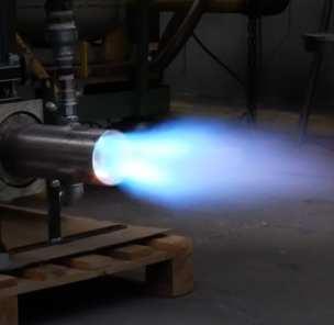
3 The EPB are monoblock metal gas burners for direct heating. These burners allow excess air settings, and stoichiometric excess gas. Depending on the size and conditions of use, this type of burner can be used for combustion of natural gas and LPG (standard version) and other types of gaseous fuels with different calorific values (special versions available on request). APPLICATIONS ¾Ceramic furnaces, or treatment with fiber coatings. ¾Tunnel or chariot furnaces ¾Dryers ¾Textile and dying machines (Rameause). ¾Stress-relieving furnaces ¾Convection furnaces for food ¾Direct and indirect air heating machines ¾Melting furnaces. CHARACTERISTICS F3007I03 GENERAL: ¾Capacity from 150 to 900 kw ¾Limit temperature C ¾Burner air and gas pressure: 30 mbar ¾Flow ratio: BIAS effect upto 1:10 ¾Flame speed: m/s ¾Low CO: <10PPM (@ 3% O 2 ) ¾Excess air: upto 1000% ¾On request UL-CSA version available MATERIAL COMPOSITION: ¾Mixer body: ¾Gas collector: ¾Baffle tube: ¾Combustion head: ¾Fixing flange: Cast iron G25 Cast iron G25 AISI304 / AISI310 AISI310 Fe F3007I04 3
4 CAPAITY PARAMETERS AND FLAME LENGTHS - EPB BURNERS The ignition of the EPB burners occurs by means of a high-voltage discharge obtained through an electrode. the detection is carried out through another electrode, or by a UV light barrier (in the version with refractory block). The adoption of flame control systems is strongly recommended in all systems operating at temperatures below 750 C (UNI EN746 / 2). Model Capacity [kw] Flame length [mm] Flame tube output diameter [mm] DESCRIPTION - EPB BURNER Flame speed[m/s] Flame ignition and detection EPB N 2 Elettrodi EN EPB N 2 Elettrodi EN EPB N 2 Elettrodi EN EPB N 2 Elettrodi EN EPB N 2 Elettrodi EN The EPB burners are "nozzle mix" type burners, the combustion agent and fuel are mixed at the combustion head to avoid dangerous backfires, also the particular shape of the combustion head allows adjustments in stoichiometric ratio and in excess air or excess gas, calibration is to be simplified by appropriate differential pressure sockets which allows the measurement of air and gas flow rates. The EPB Monoblock burners are supplied pre-calibrated with factory settings. BURNER PERFOMANCE The potential, lengths and flame speed are related to natural gas-fueled burner (8600 kcal / Nm3), placed in the combustion chamber at zero pressure above sea level, working with the 10% of excess air. ¾Chamber temperature 1000 C ¾Ambient air temperature MAXIMUM CAPACITY Max capacity Free flame applications Burner model EPB-150 EPB-300 EPB-400 EPB-600 EMB-900 Burner capacity (2% O 2 ) [kw] Combustion air flow [Nm 3 /h] Gas flow [Nm 3 /h] Burner input air pressure [mbar] 30 p gas measurement flange [mbar] 10 MINIMUM CAPACITY Min. capacity Free flame applications Bruciatore modello EPB-150 EPB-300 EPB-400 EPB-600 EMB-900 Burner capacity (2% O 2 ) [kw] Combustion air flow [Nm 3 /h] Gas flow [Nm 3 /h] 1,9 3,8 5 7,5 11,5 Burner input air pressure [mbar] 0,5 p gas measurement flange [mbar] 0,15 4
5 METHANE GAS FLOW CHART 10 EPB-150 EPB-300 EPB-400 EPB-600 EPB-900 Differential pressure at calibrated flange [mbar] 1 0,1 0,1 1 1, Natural gas 20 C P.S.=0,6 [Nm 3 /h] G3007I01 AIR FLOW CHART 100 EPB-150 EPB-300 EPB-400 EPB-600 EPB-900 Burner input pressure [mbar] ,1 1 7, Total air flow (burner + 30 C P.S.= 1 [Nm 3 /h] G3007I02 5
6 P&ID PREASSEMBLED BURNER HV 01 F 02 PSL 03 PI 04 PSH 05 S S FCV 11 GAS INLET SV 06 SV 07 FE 08 IL 09 PCV 10 FSL 15 FSH 16 BI 21 BD 17 BE 20 BT 18 BMS 19 BL 12 M PSL 13 FCV 14 M D3700I01 Pos. Description Included Not included HV 01 Gas shut-off valve X F 02 Gas filter X PSL 03 Minimum gas pressure switch X PI 04 pressure gauge X PSH 05 Maximum gas pressure swicth X SV 06 Fast opening gas safety valve X SV 07 Slow opening gas safety valve X FE 08 Calibrated flange X IL 09 Impulse line X PCV 10 Zero governor X FCV 11 Gas adjuster X BL 12 Combustion air blower X PSL 13 Minimum air pressure switch X FCV 14 Air regulation valve X FSL 15 Differential air pressure switch X FSH 16 Maximum air flow switch X BD 17 Flame detection X BT 18 Ignition transformer X BMS 19 Flame control X BE 20 Burner X BI 21 Burner ignition X 6
7 WARNINGS ¾ The ignition of the EPB burners must always be performed at minimum power, then modulating towards the maximum, facilitating the ignition and reducing output overpressure. ¾ For all low-temperature applications (up to 750 C), the burner ignition and the control of the fuel gas solenoid valves must be performed by a certified burner control device. ¾ To prevent possible damage to the burners, make sure that the blower does not send them stale air from the combustion products, oils, solvents or other substances. To avoid these conditions regularly clean the filter mounted at the blower side. If this is not enough we recommend channeling the blower intake outside the building. ¾ Check the correct connection of the supply lines after installation. Before lighting the burner, check the correctness of the combustion air and fuel gas pressure values (p. 05). ¾ The burner can only work within the indicated power range. Functioning with less or more power can compromise the performance and life span of the burner. In that case, the general warranty conditions automatically expire and ESA-PYRONICS is not responsible for any damage to property or persons. ¾ If there is trouble with other devices during the burner start-up, for the HT (High Voltage) cable connection to the ignition connector, use a connector with noise filter provided with the burner. ¾ Avoid burner ignition close to each other so as not to heat the ignition command system devices (solenoid valves and transformers). Prewash time lapse + first safety time lapse + min. of 5 sec. = time lapse between one ignition and another. (however, do not attempt more than 2 ignitions during a 30sec. time lapse). ¾ Make sure the power supply is TURNED OFF when intervening on the burner and its devices. In case of burner malfunctioning, follow the indications in the Maintenance chapter of the present manual or contact ESA-PYRONICS assistance. ¾ Any modification or repair done by third parties can compromise the application safety and automatically cause the general warranty conditions to expire. 7


8 INSTALLATION The burners of the EPB series are provided with a specific fixing flange to the furnace wall. The light obtained for the housing of the burner, must include a vacant space around it that will then be filled with fibro-ceramic mat. For installation, carefully follow the instructions below: 1 - Arrange the EPB burners far from heat sources and from products such as liquids, solvents or corrosive gases. 2 - Make sure that the housing dimensions and the centre distances of the supply lines correspond to what is specified in the "overall dimensions". 3 - Extract the burner, lifting it from the eyelets provided on the metal support frame. 4 - Remove the support frame via the four screws that hold it to the furnace attachment flange. F3007I Do not lift the burner from the gas pipe, the combustion blower or the air control valve. Provide lifting straps that only wrap the main body of the burner. 6 - Assemble the burner on the furnace wall positioned between the attachment flange and furnace wall seal (pos. 01). Tighten screws and / or nuts (pos. 02) to the furnace wall flange. 7 - Connect the fuel gas inlet pipe, fitting expansion joints in AISI before the gas cock. 8 - Make the electrical connections of ignition electrode and detection, taking care to pass the wires away from heat sources. 9 - Make sure the burner body and all metal parts connected are connected to the grounding system with suitable conductors. F3007I The connection cable from the ignition transformer to the electrode must be specific for high tension and not shielded. The length should not exceed one meter; otherwise the ignition transformer must be positioned near the burner. The HV cable must be laid away from the power cables and not in metallic conductors, ideally it should be left in the open air For more details, see the data sheet related to power transformers Make the electrical connections of the ignition and detection electrode, taking care to pass the wires away from heat sources F3007I07 8

9 IGNITION AND SETTING The operations indicated in the following chapter must be carried out by expert technicians. Failure to follow instructions may cause dangerous conditions. The burner is usually supplied with all the pre-calibrated control organs. It is therefore possible to use it without the need for adjustment. When hecking burner adjustments follow the data indicated in the testing module. SETTING THE AIR FLOW OF PREMIXTURE WHERE PROVIDED (LPG BURNER) The premix line is supplied with the burners operating with LPG. Calibration has to be done with the burner off and at minimum flow conditions. The premix line is fed from an outlet necessarily upstream of the air flow rate regulation valve). 1 - Place the burner in low capacity combustion air conditions 2 - Open the premix air cock (pos. 01). 3 - Adjust the micrometer needle valve (pos. 02) according to the following guidelines: EPB-150: Gas body pressure (pos. 03) = 2 mbar EPB-300: Gas body pressure (pos. 03) = 2 mbar EPB-400: Gas body pressure (pos. 03) = 2 mbar EPB-600: Gas body pressure (pos. 03) = 2 mbar EPB-900: Gas body pressure (pos. 03) = 2 mbar 4 - Verify however, that the minimum potential of the burner does not create soot on the combustion head and electrodes. In case it does, increase the premix air calibration. F3007I08 9
10 GENERAL MAINTENANCE PLAN Operation Type Advised time Notes High tension electrode connector O annual Ignition / detection electrode O annual Flanged tube combustion head O annual Blower filter O monthly Solenoid coils O Every two years Pressure switches O Every six months Replacement of gaskest on the gas side (*) E Every two years Burner settings E annual Premix air settings (where needed) E annual verify integrity of the outer plastic and oxidation of the internal connector and the electrode terminal. replace in case in which the terminal Kanthal is consumed. during the stop of the furnace, check that the two parts do not show signs of oxidation due to high temperature. verify degree of dirtiness, if necessaryclean from residues of dust with compressed air. Replace in case of breakage of the filter material. check the number of cycles that must not exceed what is stated by the manufacturer. check their intervention simulating an alarm. verify the absence of rupture or deformation of the material refer to the information in the testing module attached to the burner. see the Calibration of premix air flow rate section. NOTES: key O = ordinary / E = extraordinary (*) It is recommended to replace the gas side seals after each disassembly of the gas supply line 10
11 EXTRAORDINARY MAINTENANCE For correct dismantling and better maintenance of the EPB burners, meticulously follow the instructions below with the plant turned off. REPLACEMENT OF FLAME IGNITION AND DETEC- TION ELECTRODE 1 - Make sure the burner control device is not connected. 2 - Disconnect the electrical connection of the electrodes (pos. 01). 3 - Unscrew the fitting (pos. 02) from the base of the gas collector, removing the electrode (pos. 03). 4 - Replace defective electrode (pos. 03), paying attention to the correct repositioning of the new electrode. 5 - Restore the electrical connection (pos. 01). 6 - Ensure correct ignition / flame detection of the electrode D3007I02 EXTRAORDINARY MAINTENANCE For correct dismantling and better maintenance of the EPB burners, meticulously follow the instructions below with the plant turned off. BURNER IN LOCKOUT For correct dismantling and better maintenance of the EPB burners, meticulously follow the instructions with the plant turned off. In burner lockout conditions refer to the instructions of the burner control device and the relative manual to identify the cause. The following are the main cases ¾Illegal flame detection: lockout due to the detection of illegal flame signal during the phases prior to ignition or following the shutdown. The causes are to be found in the detection system (faulty sensor or presence of humidity), or in gas drawn by the safety solenoid valve that allows the burner to remain turned on. ¾Failed ignition: lockout due to missing flame formation during start-up. The causes are to be found in the ignition system (spark absence, faulty or not in the correct position) electrodes, the incorrect adjustment of the fuel flow and combustion, or in the detection system (faulty sensor or interrupted cables). Specifically, in the first two cases the flame does not trigger, whilst in the last case, the flame forms but the burner control device is not able to detect it. ¾Flame signal loss: lockout due to flame signal loss during the normal operation of the burner. The causes are to be found in the regulation of the combustion air and fuel flows (rapid changes in flow, control out of range) or in the detection system (faulty sensors, dirty or badly positioned). 11
12 OVERALL DIMENSIONS - EPB Detail burner fixing flange n 4 holes ø14 ø240 ø200 Ø101, GAS INLET Rp3/4" WALL THICKNESS "X" D3007I
13 OVERALL DIMENSIONS - EPB Detail burner fixing flange n 4 holes ø14 ø240 ø Ø114, GAS INLET Rp1" 473 WALL THICKNESS "X" D3007I
14 OVERALL DIMENSIONS - EPB Detail burner fixing flange n 4 holes ø14 ø o n114,3 421 GAS INLET Rp1" WALL THICKNESS "X" D3007I
15 OVERALL DIMENSIONS - EPB Detail burner fixing flange n 4 holes ø14 ø Ø168, GAS INLET Rp1.1/2" 629 WALL THICKNESS "X" D3007I
16 OVERALL DIMENSIONS - EPB Detail burner fixing flange ø360 ø400 n 4 holes ø Ø WALL THICKNESS "X" GAS INLET Rp1.1/2" D3007I
17 ORDERING CODES - COMPLETE BURNER EPB Model Ignition and detection EPB-150 EPB-300 EPB (see capacity table) Ign. & detect. electrode Unirod Pilot burner( 2 ) E* M P Gas adjuster Flanged tube length X With gas adjuster Without gas adjuster GA* F Indicate flame length mm (v. see Overall Dimensions)... Fuel Flange type Methane LPG Poor gas ( 1 ) CH4 GPL GP According to ESA dwg According to client dwg E* C The codes marked with an asterisk (*) identify the standard. Notes: 1 Particular performance according to gas characteristics 2 Available in models 2, 3, 4, 5 and 6 (see. Section Ignition and detection ) 17
Burners. Monoblock free flame burners EPB (E3007 rev /11/2017)
") Burners Monoblock free flame burners EPB (E3007 rev. 02-13/11/2017) GENERAL WARNINGS: DISPOSAL: ¾ All installation, maintenance, ignition and setting must be performed by qualified staff, respecting the
Burners Monoblock free flame burners EPB (E3007 rev. 02-13/11/2017) GENERAL WARNINGS: DISPOSAL: ¾ All installation, maintenance, ignition and setting must be performed by qualified staff, respecting the
Burners. Long flame burners Nozzle Mix NM - (E3501 rev /05/2015)
") Burners Long flame burners Nozzle Mix NM - (E3501 rev. 08-22/05/2015) GENERAL WARNINGS: DISPOSAL: ¾ All installation, maintenance, ignition and setting must be performed by qualified staff, respecting
Burners Long flame burners Nozzle Mix NM - (E3501 rev. 08-22/05/2015) GENERAL WARNINGS: DISPOSAL: ¾ All installation, maintenance, ignition and setting must be performed by qualified staff, respecting
Burners. Self-recuperative burners high speed free flame REKO-SIK-NxT-FF (E3901FN rev /02/2018)
") Burners Self-recuperative burners high speed free flame REKO-SIK-NxT-FF (E3901FN rev. 01-05/02/2018) GENERAL WARNINGS: DISPOSAL: ¾ All installation, maintenance, ignition and setting must be performed
Burners Self-recuperative burners high speed free flame REKO-SIK-NxT-FF (E3901FN rev. 01-05/02/2018) GENERAL WARNINGS: DISPOSAL: ¾ All installation, maintenance, ignition and setting must be performed
Burners. Self-recuperative burners high speed free flame REKO-SIK-FF (E3901F rev /08/2015)
") Burners Self-recuperative burners high speed free flame REKO-SIK-FF (E3901F rev. 05-04/08/2015) GENERAL WARNINGS: DISPOSAL: ¾ All installation, maintenance, ignition and setting must be performed by qualified
Burners Self-recuperative burners high speed free flame REKO-SIK-FF (E3901F rev. 05-04/08/2015) GENERAL WARNINGS: DISPOSAL: ¾ All installation, maintenance, ignition and setting must be performed by qualified
SELF - RECUPERATIVE BURNERS HIGH SPEED FREE FLAME REKO-SIK-FF. E3901FF rev /05/2009.
 SELF - RECUPERATIVE BURNERS HIGH SPEED FREE FLAME REKO-SIK-FF E3901FF rev. 04-06/05/2009 www.esapyronics.com GENERAL WARNINGS: DISPOSAL: - All installation, maintenance, ignition and setting must be performed
PACKAGED METALLIC BURNERS
 FEATURES PACKAGED METALLIC BURNERS FC SERIES Bulletin E00 rev0 /0/0 Burner body: Burner cone: Nozzle: Optional shield: Capacity range: Adequate to different types of gas: Excellent flame stability with:
EXCESS AIR BURNERS XNM SERIES FEATURES APPLICATIONS DESCRIPTION. Bulletin E3502 rev05 31/01/00
 EXCESS AIR BURNERS XNM SERIES FEATURES Mixer: cast iron G25 Plate: cast iron G25 Air tube: AISI304 Preheated air: up to 450 Suitable for different types of gas: CH 4 /L.P./propane/etc Standard refractory
FLAT FLAME AND EXCESS AIR BURNERS
 FLAT FLAME AND EXCESS AIR BURNERS SIDEWINDER - SW SERIES FEATURES Bulletin E303 rev04 31/01/00 Mixer body: cast iron G2 Plate: cast iron G2 Gas tube: AISI304 Pre-heated air: up to 40 Suitable for different
INFRA-RED BURNERS BR-70 SERIES FEATURES APPLICATIONS. Bulletin E3005 rev03 31/01/00
 INFRA-RED BURNERS BR-70 SERIES Bulletin E3005 rev03 31/01/00 FEATURES Mixer body: AISI304 Radiant surface: inconel Mixer: brass Low air and gas pressure required: 40 mbar Capacity of one radiant panel:
Electronics. Burner control and flame detector for permanent and not-permanent operation ESA REFLAM-H (E7802 rev /04/2017)
") Electronics Burner control and flame detector for permanent and not-permanent operation ESA REFLAM-H (E7802 rev. 01-20/04/2017) GENERAL WARNINGS: DISPOSAL: ¾ All installation, maintenance, ignition and
Electronics Burner control and flame detector for permanent and not-permanent operation ESA REFLAM-H (E7802 rev. 01-20/04/2017) GENERAL WARNINGS: DISPOSAL: ¾ All installation, maintenance, ignition and
Electronics. Microprocessor operated burner control device ESA ESTRO (E7014 rev /11/2009)
") Electronics Microprocessor operated burner control device ESA ESTRO (E7014 rev. 02-03/11/2009) GENERAL WARNINGS: DISPOSAL: ¾ All installation, maintenance, ignition and setting must be performed by qualified
Electronics Microprocessor operated burner control device ESA ESTRO (E7014 rev. 02-03/11/2009) GENERAL WARNINGS: DISPOSAL: ¾ All installation, maintenance, ignition and setting must be performed by qualified
Electronics. Pulse Firing controller for Esa Estro and Esa Reflam ESA PLEX-PULSE (E7108 rev /12/2016)
") Electronics Pulse Firing controller for Esa Estro and Esa Reflam ESA PLEX-PULSE (E7108 rev. 01-16/12/2016) GENERAL WARNINGS: DISPOSAL: ¾ All installation, maintenance, ignition and setting must be performed
Electronics Pulse Firing controller for Esa Estro and Esa Reflam ESA PLEX-PULSE (E7108 rev. 01-16/12/2016) GENERAL WARNINGS: DISPOSAL: ¾ All installation, maintenance, ignition and setting must be performed
Forced draught gas burner
 Installation, use and maintenance instructions Forced draught gas burner Code Model Type 3751982 GAS 3 519T80 291 (3) - 02/2010 DECLARATION Declaration of conformity in accordance with ISO / IEC 17050-1
INDITHERM. Low temperature gas burners
 INDITHERM Low temperature gas burners 1-2.3-1 High turndown for maximum operation flexibility. Maximum capacities up to 1800 kw. Designed for firing in indirect fired processes. Excellent combustion throughout
LFE50. UV Flame Safeguard. Siemens Building Technologies HVAC Products DETACTOGYR. Series 02
 7 783 ISO 9001 DETACTOGYR Flame Safeguard Series 02 The... together with the QRA50M / QRA51M form a self-checking flame supervision system (DETACTOGYR ) designed for use with continuously operating oil
UV Flame Supervision System
 7 783 UV Flame Supervision System DETACTOGYR LFE50 Series 02 ISO 9001 The LFE50 is a self-checking UV flame supervision system designed for use with continuously operating burners or for burners running
Electronics. Serial Gateway for Esa Estro and Esa Reflam ESA BRIDGE & ESA EXP-3 (E7015 rev /01/2017)
") Electronics Serial Gateway for Esa Estro and Esa Reflam ESA BRIDGE & ESA EXP-3 (E7015 rev. 03-13/01/2017) GENERAL WARNINGS: DISPOSAL: ¾ All installation, maintenance, ignition and setting must be performed
Electronics Serial Gateway for Esa Estro and Esa Reflam ESA BRIDGE & ESA EXP-3 (E7015 rev. 03-13/01/2017) GENERAL WARNINGS: DISPOSAL: ¾ All installation, maintenance, ignition and setting must be performed
LFE50. UV Flame Safeguard. Building Technologies Division DETACTOGYR
 7 783 DETACTOGYR Flame Safeguard The... together with the QRA50M / QRA51M form a self-checking flame supervision system (DETACTOGYR ) designed for use with continuously operating oil or gas burners or
ESA Pyronics International R&D test center
 A new frontier for the Research and Development combustion tecnologies ESA Pyronics International has, over the years, acquired a reputation on a worldwide level for the manufacturing quality of its products.
Safety. Operating instructions Ionization pilot burners ZAI, ZMI, ZKIH DANGER. Contents WARNING CAUTION Edition 12.11
 050560 Edition. D F NL I E DK S N P GR TR CZ PL RUS H www.docuthek.com Operating instructions Ionization pilot burners,, Translation from the German 0 Elster GmbH Contents Checking the usage.....................
Forced draught gas burner
 Installation, use and maintenance instructions GB Forced draught gas burner One stage operation CODE MODEL TYPE 3751782 GAS 5 517T80 291 (4) - 07/2015 Declaration of conformity in accordance with ISO /
Room sealed circuit appliance sold without the terminal or the combustion air supply and exhausted gas ducts. TYPE C 63 TYPE B TYPE B 23
 Room sealed circuit appliance sold without the terminal or the combustion air supply and exhausted gas ducts. TYPE C 63 TYPE B Type B 23 on the wall Ø 80 duct, available in the following lengths: 1000,
MULTIPLEX SELF RECUPERATIVE gas burner
 Installation - Maintenance MULTIPLEX SELF RECUPERATIVE gas burner SERIES MPSR The Nu-way Multiplex Recuperative System offers the alternative of a self-recuperative burner or a separate recuperator and
Indirect gas-fired air heater
 Indirect gas-fired air heater SERIES HD INSTALLATION AND SERVICE MANUAL MANUFACTURED BY : BROTHERS LIMITED WARNING Improper installation, modification, adjustment or maintenance may cause damage, injury
RIELLO 40 GS/M SERIES
 The Riello 40 GS/M series of two stage progressive or modulating gas burners, is a complete range of products developed to respond to any request of gas burners for hot air generator according to EN 1020.
Light oil burners. One stage operation
 Installation, use and maintenance instructions Light oil burners One stage operation CODE MODEL TYPE 3505 RDB CF 38 50 T3 350050 RDBR CF 6 50 TR 35050 RDBR CF 33 50 TR 35050 RDBR CF 38 50 T3R 350650 RDBR
MICROPROCESSOR OPERATED BURNER CONTROL DEVICE ESA ESTRO SERIE
 ESA S.r.l. Via E. Fermi, 40 I-24035 Curno (BG), Italy E7014 MICROPROCESSOR OPERATED BURNER CONTROL DEVICE ESA ESTRO SERIE INTRODUCTION ESA ESTRO is a microprocessor operated device, designed to control
RL/1 SERIES. One Stage Light Oil Burners FIRING RATES LIGHT OIL RL 34/1 MZ kw
 The RL/1 burners series covers a firing range from 107 to 398 kw, and it has been designed for use in low or medium temperature hot water boilers, hot air or steam boilers, diathermic oil boilers. Optimisation
INSTALLATION AND MANINTENANCE INSTRUCTIONS
 INSTALLATION AND MANINTENANCE INSTRUCTIONS Appr. Nr. A 9503 T - 0085 AQ 0765 PEGASUS F2 T HIGH EFFICIENCY GAS-FIRED CAST-IRON BOILERS Models 51-68 - 85-102 2 Contents 1. General technical data 2. Dimensional
ATMOSPHERIC GAS BOILER INSTALLATION, OPERATING AND MAINTENANCE MANUAL
 STREBEL GENEVA CE ATMOSPHERIC GAS BOILER INSTALLATION, OPERATING AND MAINTENANCE MANUAL INDEX TABLE 1 TECHNICAL DATA SECTION 1 SECTION 2 SECTION 3 SECTION 4 SECTION 5 SECTION 6 SECTION 7 SECTION 8 SECTION
UV - flame detector KLC 10 for oil -, gas- and dual fuel burners for intermittent burner operations
 KLC 10 Technical information UV - flame detector KLC 10 for oil -, gas- and dual fuel burners for intermittent burner operations Description The KLC 10 is a compact UV flame detector, which has been developed
Eclipse 90 UV Scanner Model A Version 1
 85 Instruction Manual 10/14/010 Eclipse 90 UV Model 5600-90A Version 1 C US Introduction This sensor features a high sensitivity ultraviolet (UV) tube for monitoring gas or oil flames that cycle on and
USERS MANUAL FOR GAS BOILERS
 USERS MANUAL FOR GAS BOILERS PLEASE READ THE MANUAL CAREFULLY: IT CONTAINS IMPORTANT INFORMATION REGARDING SAFETY, INSTALLATION, USE AND MAINTENANCE OF THE APPLIANCE MODELS: NOVADENS 24 NOVADENS 24C NOVADENS
PCH Heating Condensing Module for Air Handling and Roof Top Units
 40 Years Caring for Environment PCH Heating Condensing Module for Air Handling and Roof Top Units Efficiency as high as 105% Saving Up to 50% on Consumptions Environmentally friendly Efficiency as high
USER MANUAL. 80 cm 2 burners, glass hob AKC 820C/BLM
 USER MANUAL 80 cm 2 burners, glass hob AKC 820C/BLM For your safety These instructions have been drawn up for your safety and that of others. You are therefore requested to read them carefully before installing
ELECTRONIC FLAME SUPERVISION MULTI-BURNER
 MULTI-BURNER MODEL: SENS-A-FLAME II Revision: 0 7112 DESCRIPTION Model 7112 Sens-A-Flame II is a second generation solid-state programmable combustion safeguard for supervising multiple burner ovens, furnaces,
UV - flame detector dual fuel burners for intermittent burner operations
 KLC 11 1(formerly known as KLC 1001) Technical information UV - flame detector KLC 11 for oil -, gas- and dual fuel burners for intermittent burner operations 0085 Description The KLC 11 is a compact UV
OPERATING AND MAINTENANCE MANUAL
 OPERATING AND MAINTENANCE MANUAL NVPOM-0104 TABLE OF CONTENTS Section Page 1 SPECIFICATIONS...1 1.1 Nova Plus Specifications...1-1 1.2 Warranty...1-2 2 GENERAL BURNER DESCRIPTION...2 2.1 Burner...2-1 2.2
HG 675 CX 60 HG 675 CN 60 HG 675 CW 60
 HG 675 X 60 HG 675 CX 60 HG 675 CN 60 HG 675 CW 60 1 2 1. : 93/68: 90/396: 2006/95/CE: 2004/108/CE: - 1935/2004:. 2002/95/CE: RoHS 2.,.,,,,...,. (,..)..,,.,. ( ),,, ;,,.,.....,.,,,,,,...,. (..),,.,..,.,,,,
INDITHERM. Low temperature gas burners
 INDITHERM Low temperature gas burners 1-2.3-1 High turndown for maximum operation flexibility. Maximum capacities up to 1800 kw. Designed for firing in indirect fired processes. Excellent combustion throughout
Spark Electrodes/Flame Sensors
 Spark Electrodes/Flame Sensors For Gas Ignition Systems July 2016 DESCRIPTION Fenwal electrodes and sensors are an integral part of the ignition system for gas-fired equipment and ensure reliable ignition,
DMG 973. Gas Burner Safety Control. For 2-stage forced draught and combi oil/gas burners, facility to connect an air damper unit
 A Honeywell Company Gas Burner Safety Control For 2-stage forced draught and combi oil/gas burners, facility to connect an air damper unit Possible flame detectors: - Ionisation probe - Infrared flicker
KITCHEN EXHAUST FAN GLEC-6 INSTALLATION AND MAINTENANCE
 KITCHEN EXHAUST FAN GLEC-6 INSTALLATION AND MAINTENANCE 2 GLEC-6 - Installation and maintenance CONTENTS 1 Important information... 3 2 Safety notes... 3 3 Technical description...4 4 Transport... 6 5
DMG 973. Gas Burner Safety Control. For 2-stage forced draught and combi oil/gas burners, facility to connect an air damper unit
 certified Qualitysystem ISO 9001 / EN 29001 Reg. Nr. 10529 Gas Burner Safety Control A Honeywell Company For 2-stage forced draught and combi oil/gas burners, facility to connect an air damper unit Possible
Light oil - kerosene burner
 Installation, use and maintenance instructions Light oil - kerosene burner One stage operation CODE MODEL TYPE 374374 G3B 437T 90 (4) - 05/0 TECHNICAL FEATURES TYPE 437T Thermal power output 9 35 kw.6
Self-recuperative burner for gas
 Self-recuperative burner for gas For direct and indirect heating Economical, energy-saving operation by virtue of internal air preheating up to 650 C Uniform distribution of temperature by means of a high
SAITEK srl. Serie. < Automatic burner control unit > Casalgrande (RE) ITALY Tel Fax
 ITALY Tel Fax") Serie < Automatic burner control unit > MONO DOUBLE ELECTRODE FLAME DETECTION SAITEK srl www.saitek.it info@saitek.it Casalgrande (RE) ITALY Tel. +39 0522 848211 Fax +39 0522 849070 NOTE. AUTOMATIC BURNER
Serie < Automatic burner control unit > MONO DOUBLE ELECTRODE FLAME DETECTION SAITEK srl www.saitek.it info@saitek.it Casalgrande (RE) ITALY Tel. +39 0522 848211 Fax +39 0522 849070 NOTE. AUTOMATIC BURNER
Parts Available from
 Montage und Bedienungsanleitung Manuel d entretien Installation, use and maintenance instructions Installatie-, gebruiks- en onderhoudsvoorschriften Oδηγίες εγκατάστασης, χρήσης και συντήρησης D F GB NL
ST1. Mod. USE AND MAINTENANCE MANUAL
 Mod. USE AND MAINTENANCE MANUAL 2 Use and Maintenance Manual ---------------------------------------------------------------------------------------------------------------------------------------------------------------------------------
UV Scanner. Model Specification. Introduction. 854 Instruction Manual
 854 Instruction Manual 10/11/010 UV Model 5600-91 C US Introduction This sensor features a high temperature and high sensitivity ultraviolet (UV) tube for monitoring gas or oil flames in applications that
PEGASUS F2 N 2S. CAST IRON GAS BOILER for heating with electronic ignition and flame control INSTRUCTIONS FOR USE, INSTALLATION AND MAINTENANCE
 PEGASUS F2 N 2S CAST IRON GAS BOILER for heating with electronic ignition and flame control INSTRUCTIONS FOR USE, INSTALLATION AND MAINTENANCE cod. 3544309/0 ediz. 01/2003 Carefully read the warnings in
Eclipse Self-Check UV Scanner
 856 Instruction Manual 10/18/2010 Eclipse Self-Check UV Model 5602-91 Version 1 Introduction The self-check UV is used for continuous gas or oil flames. A mechanical shutter in the scanner closes briefly
PBG PACKAGED GAS BURNER
 INSTRUCTIONS PBG PACKAGED GAS BURNER WARNING These instructions are intended for use only by experienced, qualified combustion start-up personnel. Adjustment of this equipment and its components by unqualified
ECLIPSE INFORMATION GUIDE
 ECLIPSE INFORMATION GUIDE EXTENSO-JET SMALL BORE BURNERS Info 230 8/91 CONTENTS PAGE CONTENTS PAGE Safe Burner Operation... 2 1.0 Applications... 2 2.0 Burner Operating Parameters & Requirements 2.1 Capacities
DKG 972. Gas Burner Safety Control. For 2-stage atmospheric gas burners
 certified Qualitysystem ISO 9001 / EN 29001 Reg. Nr. 10529 Gas Burner Safety Control A Honeywell Company For 2-stage atmospheric gas burners Flame detection: - Ionisation probe - Infrared-flicker detector
LONGONI ENGINEERING SRL
 INDEX 1.1 Classification of heat exchanger and components 1.1.2 Type of heat exchanger and components 1.2 Purpose and scope of the manual 1.3 General instruction 1.4 Warning installation 1.5 Notes for
1500 SERIES SMALL CAPACITY ULTRA 2 LOW NO X TM BURNER
 CAPABILITIES Similar design for hot or cold air Good turndown with flame characteristics and direction maintained Multiple gaseous fuel capabilities including commercial and many by-product fuels FEATURES
Internet Version for Reference Only INDUCED DRAFT COMMERCIAL WATER HEATERS SUPPLEMENT INSTRUCTIONS TO PART #
 INDUCED DRAFT COMMERCIAL WATER HEATERS SUPPLEMENT INSTRUCTIONS TO PART #238-39387-00 THIS INSTRUCTION SUPPLEMENT IS ONLY INTENDED TO GIVE INSTALLATION INSTRUCTIONS AND INFORMATION RELATED TO THE INDUCED
Revitalize Building Mechanical Systems (4619)
") SECTION 235216 FIRE-TUBE CONDENSING BOILERS PART 1 - GENERAL 1.1 RELATED DOCUMENTS A. Drawings and general provisions of the Contract, including General and Supplementary Conditions and Division 01 Specification
SECTION 235216 FIRE-TUBE CONDENSING BOILERS PART 1 - GENERAL 1.1 RELATED DOCUMENTS A. Drawings and general provisions of the Contract, including General and Supplementary Conditions and Division 01 Specification
Installation & Maintenance Manual
 Installation & Maintenance Manual Series NG fully automatic gas burner Models NG125/NG150 : High/Low Gas Burner 11/12 Tel: +44 (0) 1905 794331 Fax: +44 (0) 1905 794017 Email: info@nu-way.co.uk Web: www.nu-way.co.uk
PCH/new Series. High performance, total flexibility
 PCH/new Series High performance, total flexibility PCH/new Installation in Air Handling Unit Very Low Emissions NOx lower than 30 ppm : Class 5 Capacity Range 14 models from 5 kw to 400kW Automatic Control
southbend A MIDDLEBY COMPANY INSTALLATION AND OPERATION MANUAL CG214 (E) CG314 (E) CG414 (E) CG220 (E) CG320 (E) CG325 (E) GAS BOILERS MODELS:
 CG314 (E) CG414 (E) CG220 (E) CG320 (E) CG325 (E) GAS BOILERS MODELS:") INSTALLATION AND OPERATION MANUAL GAS BOILERS MODELS: CG214 (E) CG314 (E) CG414 (E) CG220 (E) CG320 (E) CG325 (E) southbend A MIDDLEBY COMPANY 1100 Old Honeycutt Road Fuquay-Varina, NC 27526 (919) 552-9161
INSTALLATION AND OPERATION MANUAL GAS BOILERS MODELS: CG214 (E) CG314 (E) CG414 (E) CG220 (E) CG320 (E) CG325 (E) southbend A MIDDLEBY COMPANY 1100 Old Honeycutt Road Fuquay-Varina, NC 27526 (919) 552-9161
BIX B-One 100 kw INSTALLATION GUIDE
 BIX B-One 100 kw INSTALLATION GUIDE Dear Customer, We thank you for choosing our product. The Bix B-One 100 Kw is a burner of advanced concept and technology, with a high reliability and construction quality.
A-8-01 Typical questions and answers on the boiler specifications on tender and boiler contract documents
 Boiler specifications A-8-01 Typical questions and answers on the boiler specifications on tender and boiler contract documents Burner General: Q. Burner and burner safeguards shall comply with the CGA
Oil burners Brûleurs fioul Stookoliebranders
 Installation, use and maintenance instructions Manuel d entretien Installatie-, gebruiks- en onderhoudsvoorschriften GB F NL Oil burners Brûleurs fioul Stookoliebranders One stage operation Fonctionnement
So old fashioned... As the combustion chamber is completely room sealed, it does not release any smells and does not dirty.
 ARREDO E BENESSERE So old fashioned... An intelligent choice When on a cold winters night the warm glowing flames of the KALDUS boiler are there to welcome you back home, you will be pleased that you decided
USER MANUAL. 60cm, 3 burners, Hob AKC 630
 USER MANUAL 60cm, 3 burners, Hob AKC 630 For your safety These instructions have been drawn up for your safety and that of others. You are therefore requested to read them carefully before installing
Specifications of V-Line burners
 Duct Burners - V-Line 4-22.5-7 Specifications of V-Line burners V-Line burner firing on natural gas - constant combustion air 60 F - 21% O 2 combustion air - 50% rel. humidity - natural gas with 1000 Btu/ft³
W - WR - WD. Technical information W- WR - WD. Gas-fired convection heaters with fan
 Gas-fired convection heaters with fan W - WR - WD Technical information A2B srl - Via d Ancona, 37-60027 Osimo (An) Tel. 071.723991 - Fax 071.7133153 - Web Site: www.accorroni.it - E-mail: a2b@a-2-b.it
Flame Safeguard Fault Code Diagnostics
 Vino s Vine Tech Tips Series 02/2013 Flame Safeguard Fault Code Diagnostics As manager of Tech Services, it probably comes as no surprise I spend some time discussing fault codes and corresponding corrective
RS /E-EV C01 SERIES
 The well-known RS 300-800/E-EV BLU Burner Series, till now available up to 8 MW, has been upgraded with two new powerful burner models, the RS 1000-1200/E-EV C01 models that extend his max output up to
GP COMBUSTION EQUIPMENT INC 100 Sheldon Dr., Units 16/17 Cambridge, Ontario N1R 7S7. Model C Forced Draft Burners. Natural Gas or Propane MODEL C10
 Model C Forced Draft Burners Natural Gas or Propane MODEL C10 MODEL C4 GP COMBUSTION EQUIPMENT INC 100 Sheldon Dr., Units 16/17 Cambridge, Ontario N1R 7S7 Telephone: (519) 620-0230 Telefax: (519) 620-0232
DMG 970. Gas Burner Safety Control. For 2-stage forced draught and combi oil/gas burners
 certified Qualitysystem ISO 9001 / EN 29001 Reg. Nr. 10529 Gas Burner Safety Control A Honeywell Company For 2-stage forced draught and combi oil/gas burners Possible flame detectors: - Ionisation probe
INFRARED PARAFfIN / KEROSENE / model No: ir20.v2 1. SAFETY INSTRUCTIONS RECOMMENDED FUSE RATING: 5AMP
 InstructioNS for: INFRARED PARAFfIN / KEROSENE / diesel HEATER model No: ir20.v2 Thank you for purchasing a Sealey product. Manufactured to a high standard this product will, if used according to these
Installation & Maintenance Manual
 Installation & Maintenance Manual MOL 200 S1L (B30A) Oil Burner 11/12 Tel: +44 (0) 1905 794331 Fax: +44 (0) 1905 794017 Email: info@nu-way.co.uk Web: www.nu-way.co.uk DESCRIPTION COMPONENTS 1. Shrouded
Rapid. Suspended Warm Air Heater. Caring for the environment!
 Rapid Suspended Warm Air Heater Caring for the environment! RAPID The QUICK and ECOLOGICAL Suspended Heater Our RAPID heaters were conceived and designed for the heating of industrial and commercial buildings.
MONOBLOCK NG SERIES GAS BURNERS INSTALLATION, OPERATING AND MAINTENANCE MANUAL
 MONOBLOCK NG SERIES GAS BURNERS INSTALLATION, OPERATING AND MAINTENANCE MANUAL MODULATING OPERATION ECO 50 NG ECO 55 NG ECO 60 NG ECO 65 NG ECO 70 NG www.ecostar.com.tr DEAR USER, ECOSTAR ECO 50 NG, ECO
INFRARED RADIANT GAS SYSTEMS FOR THERMAL TREATMENTS
 INFRARED RADIANT GAS SYSTEMS FOR THERMAL TREATMENTS www.infragas.com INFRAGAS IR CATALYTIC GAS HEATERS WHO WE ARE Since 1971 INFRAGAS designes and produces infrared catalytic gas systems specific for surface
USE AND INSTALLATION HANDBOOK
 Date : 30/10/14 Rev. 02 PR.T : FG006203 USE AND INSTALLATION HANDBOOK (SLA1) ALARM1, ALARM2 ALARM WITH BUFFER BATTERY Via Enrico Fermi, 8-35020 Polverara PD Tel.049/9772407 Fax.049/9772289 www.fourgroup.it
LOW NOx MODULATING GAS BURNERS
 RS/E - RS/EV BLU SERIES LOW NOx MODULATING GAS BURNERS RS/E - RS/EV BLU SERIES RS 300/E BLU 500/1350 3800 kw RS 400/E BLU 800/1800 4500 kw RS 300/EV BLU 500/1350 3800 kw RS 400/EV BLU 800/1800 4500 kw
FLAME115 INFRARED HEATER SERVICE MANUAL INDEX FIRE 115 WARNING
 FLAME115 INFRARED HEATER SERVICE MANUAL INDEX 1. CONTROLS AND COMPONENTS 2. FLAME CONTROL CYCLES 3. MAINTENANCE SCHEDULE 4. TROUBLESHOOTING GUIDE 5. REPAIR PROCEDURES 1. FAN MOTOR ASSEMBLY 2. FUEL FILTER
Gas Instantaneous Water Heater
 6 720 607 823 GB (06.06) SM Installation and Operating Instructions Gas Instantaneous Water Heater WR10..B... WR11..B... With electronic ignition and triple safety system consisting of ionisation detector,
HANDBOOK REGULATOR VALVES. Ed REGULATOR VALVES RP-ED 01/ ENG 1
 HANDBOOK Ed. 2017 RP-ED 01/2017 - ENG 1 DIRECTIVE 2014/68/EU ISSUED OF THE EUROPEAN PARLIAMENT AND OF THE COUNCIL OF 15 MAY 2014 ON PRESSURE EQUIPMENT Directive 2014/68/EU (PED Recast) applies to the design,
A AD Oil burners fuel unit. deltapumps.com. DE A-AD_en_0709.pdf Page 1/1
 A AD Oil burners fuel unit deltapumps.com DE116-0709 A-AD_en_0709.pdf - 16.11.09 Page 1/1 Oil burners fuel unit Type A, AD 1- Applications The DELTA aluminium fuel unit type A is an efficient and modern
A series of technical features make this gas detector extremely versatile, reliable, accurate, and safe.
 Belonging to Made in Italy GS911K Gas Detector GS911K Using the catalytic sensor inside it, the GS911K detector detects the presence of explosive gas such as: Methane, LPG, with trip sensitivity calibrated
Oil burners fuel unit with solenoid valve
 Oil burners fuel unit with solenoid valve Type VM www.deltapumps.com VM1 - VM4U flanged Certified Quality System Printed in Italy - DE112/0404 Oil burners fuel unit with solenoid valve Type VM The DELTA
HOT GAS GENERATOR INSTALLATION, OPERATING AND MAINTENANCE MANUAL
 HOT GAS GENERATOR INSTALLATION, OPERATING AND MAINTENANCE MANUAL SHG 25 SHG 50 SHG 75 SHG 100 SHG 150 SHG 200 SHG 250 SHG 500 SHG 750 SHG 1000 SHG 1500 SHG 2000 SHG 2500 SHG 3000 www.ecostar.com.tr DEAR
RS /E-EV C01 SERIES
 The well-known RS 300-800/E-EV Burner Series, till now available up to 8 MW, has been upgraded with two new powerful burner models, the RS 1000-1200/E-EV models that extend his max output up to 12 MW and
Heating Equipment. gas boilers RX GB. installation and servicing instructions
 Heating Equipment gas boilers RX GB installation and servicing instructions CONTENTS 1 TECHNICAL FEATURES AND DIMENSIONS 1.1 BOILER DESCRIPTION.............................................. page 1 1.2
INDUSTRIAL MICRODIFFUSION OIL BURNERS
 Operations and Maintenance Manual for INDUSTRIAL MICRODIFFUSION OIL BURNERS Models MD-25-O MD-2500-O December 2012 Copyright 2012 Periflame, Design Guide 112 Industrial Oil Burners, 12/01/2012 Page 1 Table
DESIGNING A COMBUSTION AIR/GAS PRE MIX SYSTEM FOR RED RAY INFRARED PROCESS BURNERS
 DESIGNING A COMBUSTION AIR/GAS PRE MIX SYSTEM FOR RED RAY INFRARED PROCESS BURNERS 1. Determine load requirements based on application () 2. Choose burner type based on process / application / requirements
Installation and Operating Instructions
 Installation and Operating Instructions Models: Verso 4G Hob As part of Parmco Appliances commitment to improving and updating product ranges, we reserve the right to alter, change and update technical
INSTRUCTION MANUAL FOR OIL BURNER MODELS
 INSTRUCTION MANUAL FOR OIL BURNER MODELS X400 Bio B10 E90-803-001-001-03 Rev 13-1 - Contents Technical specifications Technical data... 3 Working field... 3 Dimensions... 4 Head and electrode settings...
"NP" & "RG" AIRFLO. In-duct firing line burner
 "NP" & "RG" AIRFLO In-duct firing line burner Duct burners - NP & RG AIRFLO 4-21.5-1 For direct fired fresh air heating applications Operates economically (100 % thermal efficiency) and installs easily
DH-Direct Fired Poultry Farm Diesel Heater
 DH-Direct Fired Poultry Farm Diesel Heater Comparison of Diesel Heater to Gas Heater Diesel LPG Gas LPG Gas KW 43 70 120 Fuel consumption/hr 3 5.1 8.8 Heat output 37000 60000 100000 Cost of fuel/lit or
Contents. 1. Instructions for safety and use 20
 Contents 1. Instructions for safety and use 20 2. Positioning in the counter top 21 2.1 Fixing to the supporting structure 21 2.2 Positioning the adhesive sponge 22 2.3 Positioning the fastening clips
Design Guide /12/2008. Eclipse RatioAir Burners RA Series Version 1
 Design Guide 115 11/12/2008 Eclipse RatioAir Burners RA Series Version 1 Co p y r i g h t Disclaimer Notice Copyright 2005 by Eclipse, Inc. All rights reserved worldwide. This publication is protected
AUTOMATIC BURNER CONTROL SYSTEM SAFETY INFORMATION CONFORMITY
 AUTOMATIC BURNER CONTROL SYSTEM The burner control unit Quad400 is suitable for the control of direct ignition burners up to 350 kw, pursuant to EN 746-2. Flame control by means of UV scanner or ionization
LISEO Insert. European Standard Certification UNE EN inserts. LISEO s.r.o. Folknářská 1246/21 Děčín 2 Nové Město
 LISEO Insert European Standard Certification UNE EN-13229 inserts LISEO s.r.o. Folknářská 1246/21 Děčín 2 Nové Město 405 02 INTRODUCTION.4 1. GUARANTEE CONDITIONS.4 1.1. SAFETY WARNINGS....4 1.2. GUARANTEE
A/23 MFFI - A/27 MFFI
 A/23 MFFI - A/27 MFFI G.C.N. 47-6-0 / 47-6-2 Servicing Instructions Type C Boilers LEAVE THESE INSTRUCTIONS ADJACENT TO THE GAS METER TABLE OF CONTENTS Page No.. SERVICING INSTRUCTIONS. Replacement of