Artful Inverter. Introduction and Features. Model. Remarks
|
|
|
- Lawrence Powell
- 6 years ago
- Views:
Transcription


1 Artful Inverter 1 Introduction and Features Model Remarks

2 Model Remarks V


3 Artful Inverter Model Remarks
4 2 Specifications and Technical Parameters Model Function Rated Voltage Rated Frequency Total Capacity (W/Btu/h) Power Input (W) Rated Input (W) Rated Current (A) Air Flow Volum e (m 3 /h) (H/M/L) Dehumidifying Volume (l/h) EER / C.O.P (W/W) Energy Class Indoor unit Model of Indoor Unit Fan Motor Speed (r/min) (H/M/L) Output of Fan Motor (w) Input of Heater (w) Fan Motor Capacitor (uf) Fan Motor RLA(A) Fan Type-Piece Diameter-Length (mm) Evaporator Pipe Diameter (mm) Row-Fin Gap(mm) Coil length (l) x height (H) x coil width (L) Swing Motor Model Output of Swing Motor (W) Fuse (A) Sound Pressure Level db (A) (H/M/L) Sound Power Level db (A) (H/M/L) Dimension (W/H/D) ( mm) Dimension of Package (L/W/H) ( mm) Net Weight /Gross Weight (kg) GWHN09AANK3A1A COOLING HEATING V~ 50Hz 2600W / 9000(Btu/h) 2800W / 9500(Btu/h) / 3.61 A GWHN09AANK3A1A/I 1250/1150/1000/ / Cross flow fan 1 Ø Aluminum fin-copper tube Ø MP28VB 2 PCB 3.15A Transformer 0.2A 37/35/31/27 49/47/43/ /13
5 Artful Inverter Outdoor unit Model of Outdoor Unit Compressor Manufacturer/trademark Compressor Model Compressor Type L.R.A. (A) Compressor RLA(A) Compressor Power Input(W) Overload Protector Throttling Method Starting Method Working Temp Range ( ) Condenser Pipe Diameter (mm) Rows-Fin Gap(mm) Coil length (l) x height (H) x coil width (L) Fan Motor Speed (rpm) Output of Fan Motor (W) Fan Motor RLA(A) Fan Motor Capacitor (uf) Air Flow Volume of Outdoor Unit Fan Type-Piece Fan Diameter (mm) Defrosting Method Climate Type Isolation Moisture Protection Permissible Excessive Operating Pressure for the Discharge Side(MPa) Permissible Excessive Operating Pressure for the Suction Side(MPa) Sound Pressure Level db (A) (H/M/L) Sound Power Level db (A) (H/M/L) Dimension (W/H/D) ( mm) Dimension of Package (L/W/H)( mm) Net Weight /Gross Weight (kg) GWHN09AANK3A1A/O Hitachi ASG102CV-B7AT Rotary KA-172-LYGN914 Capillary Capacitor 16-30ºC/-7-48ºC Aluminum fin-copper tube Ø Axial fan 1 Ø400 Auto defrost T1 I IP / 30 Connec tion Pipe Refrigerant Charge (kg) Length (m) Gas additional charge(g/m) Outer Diameter Max Distance R410A/ Liquid Pipe Ø6(1/4 ) Gas Pipe Ø9.52(3/8 ) Height (m) 10 Length (m) 20 Parameter data are subject to change withour prior notice. Refer to the nameplate of the unit.
6 Model Function Rated Voltage Rated Frequency Total Capacity (W/Btu/h) Power Input (W) Rated Input (W) Rated Current (A) Air Flow Volum e (m 3 /h) (H/M/L) Dehumidifying Volume (l/h) EER / C.O.P (W/W) Energy Class Indoor unit Model of Indoor Unit Fan Motor Speed (r/min) (H/M/L) Output of Fan Motor (w) Input of Heater (w) Fan Motor Capacitor (uf) Fan Motor RLA(A) Fan Type-Piece Diameter-Length (mm) Evaporator Pipe Diameter (mm) Row-Fin Gap(mm) Coil length (l) x height (H) x coil width (L) Swing Motor Model Output of Swing Motor (W) Fuse (A) Sound Pressure Level db (A) (H/M/L) Sound Power Level db (A) (H/M/L) Dimension (W/H/D) ( mm) Dimension of Package (L/W/H) ( mm) Net Weight /Gross Weight (kg) GWHN12ABNK3A1A COOLING HEATING V~ 50Hz 3500W / 12000(Btu/h) 3800W / 12800(Btu/h) / 3.61 A GWHN12ABNK3A1A/I 1350/1150/1050/ / Cross flow fan 1 Ø Aluminum fin-copper tube Ø MP28VB 2 PCB 3.15A Transformer 0.2A 39/35/30/27 52/47/42/ /15
7 Artful Inverter Outdoor unit Model of Outdoor Unit Compressor Manufacturer/trademark Compressor Model Compressor Type L.R.A. (A) Compressor RLA(A) Compressor Power Input(W) Overload Protector Throttling Method Starting Method Working Temp Range ( ) Condenser Pipe Diameter (mm) Rows-Fin Gap(mm) Coil length (l) x height (H) x coil width (L) Fan Motor Speed (rpm) Output of Fan Motor (W) Fan Motor RLA(A) Fan Motor Capacitor (uf) Air Flow Volume of Outdoor Unit Fan Type-Piece Fan Diameter (mm) Defrosting Method Climate Type Isolation Moisture Protection Permissible Excessive Operating Pressure for the Discharge Side(MPa) Permissible Excessive Operating Pressure for the Suction Side(MPa) Sound Pressure Level db (A) (H/M/L) Sound Power Level db (A) (H/M/L) Dimension (W/H/D) ( mm) Dimension of Package (L/W/H)( mm) Net Weight /Gross Weight (kg) GWHN12ABNK3A1A/O LANDA QXA-133uB030 Rotary B E Capillary Capacitor 16-30ºC/-7-48ºC Aluminum fin-copper tube Ø Axial fan 1 Ø400 Auto defrost T1 I IP / 44 Connec tion Pipe Refrigerant Charge (kg) Length (m) Gas additional charge(g/m) Outer Diameter Max Distance R410A/ Liquid Pipe Ø6(1/4 ) Gas Pipe Ø12(1/2 ) Height (m) 10 Length (m) 20 Parameter data are subject to change withour prior notice. Refer to the nameplate of the unit.
8 Model Function Rated Voltage Rated Frequency Total Capacity (W/Btu/h) Power Input (W) Rated Input (W) Rated Current (A) Air Flow Volum e (m 3 /h) (H/M/L) Dehumidifying Volume (l/h) EER / C.O.P (W/W) Energy Class Indoor unit Model of Indoor Unit Fan Motor Speed (r/min) (H/M/L) Output of Fan Motor (w) Input of Heater (w) Fan Motor Capacitor (uf) Fan Motor RLA(A) Fan Type-Piece Diameter-Length (mm) Evaporator Pipe Diameter (mm) Row-Fin Gap(mm) Coil length (l) x height (H) x coil width (L) Swing Motor Model Output of Swing Motor (W) Fuse (A) Sound Pressure Level db (A) (H/M/L) Sound Power Level db (A) (H/M/L) Dimension (W/H/D) ( mm) Dimension of Package (L/W/H) ( mm) Net Weight /Gross Weight (kg) GWHN18ACNK3A1A COOLING HEATING 220V~240V 50Hz 18000Btu/h 19500Btu/h 1640W /3.4 A/B GWHN18ACNK3A1A /I Cool:1380/1150/1050/950 Heat:1400/1200/1100/ / Cross flow fan 1 Ø98 X 733 Aluminum fin-copper tube Ø X25.4X301 MP28VB 2 PCB 3.15A Transformer 0.4/0.1A 45/38/36/33 55/48/46/ X300X X390X280 13/18
9 Artful Inverter Outdoor unit Model of Outdoor Unit Compressor Manufacturer/trademark Compressor Model Compressor Type L.R.A. (A) Compressor RLA(A) Compressor Power Input(W) Overload Protector Throttling Method Starting Method Working Temp Range ( ) Condenser Pipe Diameter (mm) Rows-Fin Gap(mm) Coil length (l) x height (H) x coil width (L) Fan Motor Speed (rpm) Output of Fan Motor (W) Fan Motor RLA(A) Fan Motor Capacitor (uf) Air Flow Volume of Outdoor Unit Fan Type-Piece Fan Diameter (mm) Defrosting Method Climate Type Isolation Moisture Protection Permissible Excessive Operating Pressure for the Discharge Side(MPa) Permissible Excessive Operating Pressure for the Suction Side(MPa) Sound Pressure Level db (A) (H/M/L) Sound Power Level db (A) (H/M/L) Dimension (W/H/D) ( mm) Dimension of Package (L/W/H)( mm) Net Weight /Gross Weight (kg) GWHN18ACNK3A1A /O Shanghai Hitachi ASH210SV-C8LU ROTARY PUT-IN Capillary Capacitor -7 T 46 Aluminum fin-copper tube Ø X660X Axial fan 2 Ø473 Auto defrost T1 I IP X685X X720X428 56/60 Connec tion Pipe Refrigerant Charge (kg) Length (m) Gas additional charge(g/m) Outer Diameter Max Distance g Liquid Pipe Ø6(1/4 ) Gas Pipe Ø12(512 ) Height (m) 15 Length (m) 20 Parameter data are subject to change withour prior notice. Refer to the nameplate of the unit.
10 Model Function Rated Voltage Rated Frequency Total Capacity (W/Btu/h) Power Input (W) Rated Input (W) Rated Current (A) Air Flow Volum e (m 3 /h) (H/M/L) Dehumidifying Volume (l/h) EER / C.O.P (W/W) Energy Class Indoor unit Model of Indoor Unit Fan Motor Speed (r/min) (H/M/L) Output of Fan Motor (w) Input of Heater (w) Fan Motor Capacitor (uf) Fan Motor RLA(A) Fan Type-Piece Diameter-Length (mm) Evaporator Pipe Diameter (mm) Row-Fin Gap(mm) Coil length (l) x height (H) x coil width (L) Swing Motor Model Output of Swing Motor (W) Fuse (A) Sound Pressure Level db (A) (H/M/L) Sound Power Level db (A) (H/M/L) Dimension (W/H/D) ( mm) Dimension of Package (L/W/H) ( mm) Net Weight /Gross Weight (kg) GWHN24ACNK3A1A COOLING HEATING 230V~ 50HZ /3.3 A GWHN24ACNK3A1A/I 1250/1100/950/ / Cross flow fan 2 φ98 X 424 Aluminum fin-copper tube X286 X25.4 MP35XX 4 PCB 3.15A Transformer 0.2A 59/57/52/47 49/4742/ X330X208 / /
11 Artful Inverter Outdoor unit Model of Outdoor Unit Compressor Manufacturer/trademark Compressor Model Compressor Type L.R.A. (A) Compressor RLA(A) Compressor Power Input(W) Overload Protector Throttling Method Starting Method Working Temp Range ( ) Condenser Pipe Diameter (mm) Rows-Fin Gap(mm) Coil length (l) x height (H) x coil width (L) Fan Motor Speed (rpm) Output of Fan Motor (W) Fan Motor RLA(A) Fan Motor Capacitor (uf) Air Flow Volume of Outdoor Unit Fan Type-Piece Fan Diameter (mm) Defrosting Method Climate Type Isolation Moisture Protection Permissible Excessive Operating Pressure for the Discharge Side(MPa) Permissible Excessive Operating Pressure for the Suction Side(MPa) Sound Pressure Level db (A) (H/M/L) Sound Power Level db (A) (H/M/L) Dimension (W/H/D) ( mm) Dimension of Package (L/W/H)( mm) Net Weight /Gross Weight (kg) GWHN24ACNK3A1A/O PANASONIC WANBAO COMPRESSOR (GUANGZHOU) CO,.LTD 5VS245EAA21 转子式 Internal Capillary Capacitor -15~54 铝箔铜管 X630X / Axial fan Auto defrost T1 I IP /700/ /750/450 / Connec tion Pipe Refrigerant Charge (kg) Length (m) Gas additional charge(g/m) Outer Diameter Max Distance 1900 / 50 Liquid Pipe 9.52 Gas Pipe 16 Height (m) 15 Length (m) 30 Parameter data are subject to change withour prior notice. Refer to the nameplate of the unit.
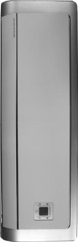
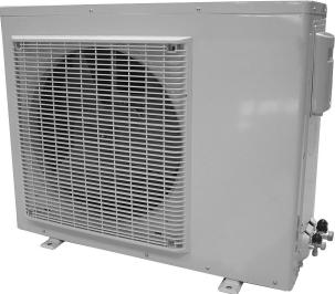
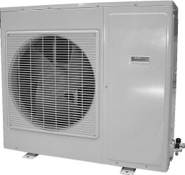
12 3 Parts name Indoor Unit Front panel Air in Displayer Power plug Wrapping tape Filter Guide louver Air out Wall pipe Setting Temp. Remote controller Displayer Heat Power/Run Cool Dry Reciver window Air in Outdoor Unit Big handle Drainage pipe Air out Note: This photo is about the models of 9K, 12K, the appearance of model of 18K and 24K are a little different from this picture.
13 Artful Inverter 4 Outline and Installing Dimension Outline and Installing Dimension of Indoor Unit Left Tube-exit Sign Right Tube-exit Sign Dimension Applicable models Unit:mm Ceiling Wall-mounted plate
14 Outline and Installing Dimension of Outdoor Unit (1) Applicable to Handle Over 600 Over 600 Unit:mm Over 600 Over 600 Bolt Nut Wrench
15 Artful Inverter Outline and Installing Dimension of Outdoor Unit (2) Applicable to Unit:mm Over 600 Over 600 Over 600 Over 1000 Bolt Nut Wrench
16 Outline and Installing Dimension of Outdoor Unit (3) Applicable to Unit:mm Over 100 Over 600 Over 600 Over 100 Bolt Nut Wrench
17 Artful Inverter 5 Electrical Diagram
18
19 Artful Inverter 6 Manual of functions of remote controller and operation method Manual of functions of remote controller This function manual is for: Temperature parameter The room setting temperature(tpreset) The room ambient temperature (Tamb) Basic Functions Once energized, the compressor should in no way be restarted unless after 3-minute time interval at least. For the first energization, the compressor will be started without 3-minute lag. The compressor, once started,will not be stopped within 6 minutes with the change of room temperature. Cooling Mode Cooling Conditions and Process If ambient temperature is higher than presetting temperature, compressor, outdoor fan will run, indoor fan will run at setting fan speed. If ambient temperature is lower than presetting temperature, compressor, outdoor fan will stop to run, indoor fan will run at setting fan speed. Under this mode the setting temperature range is16 ~30. Protection Antifreeze Protection If it is detected that the system is under antifreeze protection, the compressor and outdoor fan will be stopped, Antifreeze protection is released when temp. is too high DRY Modes The conditions and process of DRY Setting dry, compressor will run or stop according to actual ambient information,indoor fan will run with low fan speed. Under this mode the setting temperature range is16 ~30. Heating Mode(No this function for Cooling only unit) Heating Condition and Process If set up heating, when ambient temp., is lower than setting temperature, compressor, outdoor fan will run, indoor fan will run at setting fan speed; If ambient temperature is higher than setting temperature, compressor, outdoor fan will stop to run, indoor fan will run. Under this mode, the temperature can be set within a range from 16 to 30. Protection funtion Anti-cool wind: When heating started up, in order to avoid cool air blow out, the compressor will be delayed 0-3mins to start up; firstly it will run at low speed then will run at presetting fan speed or directly turn to run at setting fan speed. Anti-high temperature: in heat mode, when detected the temperature is higher, outdoor unit will stop to run; If temp. descend, outdoor fan will resume to run. Blowing surplus heat: In heat mode, due to temperature reached, compressor, outdoor fan will stop running, indoor fan will accord to actual circumstance will run at low fan speed for a while then stop running. Defrosting This unit adopt intelligent defrosting, it can defrost according to the frosting conditions and display H1. Fan mode The indoor fan will run at preset speed. Auto mode Under this mode, the system will automatically select its run mode (cool, dehumidify, or fan) with the change of ambient temperature, the protection function is the same with that of cool, heat mode. Other control Sleep If set sleep for several minutes,unit will adjust the setting temp. according to intelligent judgement when unit is cool or heat mode.
20 Up\Down swing fan control Swing for timer setting/fully swing/swing stop, the user can set up swing by wireless remteo control or adjust the position of swing stop. Buzzer The air conditioner will send out "Hua" alert when it is energized or receives a control command. Press key After powered on, unit runs with auto mode when you press this key. Unit will be off when you press this key again. Displayer Running figure and mode figure display After powered on, the figure will be displayer,then only Power/running indicator turn on. When using remote controller to open unit,it will turn on,at the same time to display current setting running modes Run and cool lights are green under the cool and auto cool mode Run and heat lights are green under the heat and auto heat mode. Run light is green under fan and auto fan mode. Run and dehumidify lights are green under the dehumidify mode. If turn off light key,then turned off all display(it's available when unit is off) After setting sleep function,displayer continus former display. it's to say sleep function don't influence the ON/OFF of light Dual 8 display The nixie tube will display the setting temp.(setting range is ).Under aoto mode cool and fan display 25.It displays 20, cool controller only display 25 and motor lock mulfunction display H6 under heat mode.it display H1 under defrost mode. Accessional display When air conditioner is running and light function is set up as ON, four pieces decoration rim will display. Automatic Control of Fan Speed The indoor fan will automatically select high, medium or low speed with the change of ambient temperature. Timer funticon Setting time-on,when it's reach the setting time,unit will run according to the setting mode.setting time-off,unit will auto be off according to the setting time PG motor lock protection When turn on the fan motor,ifmotor continuously run for a while and the running speed is very slow,in order to prevent motor automatically self-protection,it will stop running and display lock;if currently turns unit on,that dual 8 will display lock error code H6;If current is unit off,unit will not display the block error information. Dry function The dry off is defaulted on the wireless remote control. This function can be set up by wireless remote control. Under Cool mode, to set up Dry function, after unit turned off, indoor fan will run a few minutes, after the water of unit inside has been dried off, the function will be automatically turned off. TURBO function In Cool and Heat modes (Auto, Dehumidifying, Fan modes without turbo function), press the Turbo function, the "Turbo" will be displayed on wireless remote control, the fan speed will not be changed, at the same time, the indoor fan will run at high speed; When repressed this button, Turbo function will be exited, the "Turbo" on displayer will disappear, indoor fan will run at presetting fan speed, the fan speed will change accordingly. Memory Upon re-energization after de-energization, the system will run under the status as such prior to de-energization.
21 Artful Inverter Manual of functions of remote controller This function manual is for: Temperature parameter The room setting temperature(tpreset) The room ambient temperature (Tamb) Basic Functions Once energized, the compressor should in no way be restarted unless after 3-minute time interval at least. For the first energization, the compressor will be started without 3-minute lag. The compressor, once started,will not be stopped within 6 minutes with the change of room temperature. Cooling Mode Cooling Conditions and Process When T amb. Tpreset 1, in which case the compressor and outdoor fan will start, and the indoor fan will run at setting speed. When T amb. Tpreset 1, the compressor and the outdoor fan will stop, the indoor fan will run at setting speed. When Tpreset 1 T amb Tpreset 1, the unit will keep the original running status. Under this mode, the switch valve will not be powered on, and the setting temperature range is16 ~30. Tpreset Tamb. Start cooling Original running status Tpreset 6mins. 3mins. 6mins. Stop cooling Compressor Outdoor fan Indoor fan Setting fan speed Run Stop Protection Antifreeze Protection If it is detected that the system is under antifreeze protection, the compresor will stop and outdoor fan will stop running, the indoor fan will run at low speed. When antifreeze protection is released and the compressor has stopped for 3 minutes, the complete unit will resume its original operating status. During anti-freezing protection Compressor 3mins. Outdoor fan Indoor fan Setting fan speed Run Stop Overcurrent Protection If it is detected that the system exceeds 22A in 3 successive seconds,only the indoor fan run. After three minutes and overcurrent protection is released, the main unit will resume its original operating status. If it is 6 times continuously detected overcurrent protection (if the compressor has run over 5mins continuously, the times of protection will be cleared), the main unit will be stopped and the nixie tube will display the code"e5", the running indicator will blink. Dehumidifying Mode
22 Dehumidifying Conditions and Process When T amb. Tpreset 2, the unit will run under dehumidifying and cooling mode, in which case the compressor, outdoor fan will run, and indoor fan will run at low speed. When Tpreset 2 Tamb. Tpreset 2, the unit will run under dehumidifying mode, in which case the compressor and outdoor fan will be stopped after running 6 minutes,after 4 minutes, the compressor and outdoor fan will be restarted. Dehumidifying process is repeated in cycle.indoor fan will run at low speed. When Tamb. Tpreset 2, the compressor, outdoor fan and indoor fan will be stopped. Under this mode, the four-way valve will be de-energized and the temperature can be set from 16 to 30, the displayer will display running signal, dry signal and setting temperature. Tamb. Start cooling Tpreset Tpreset Compressor Outdoor fan 6mins. 6mins. 4mins. 4mins. Start dehumidifying Stop running Indoor fan Low fan speed Run Stop Protection Antifreeze Protection Under dehumidifying and cooling mode, if it is detected that the system is under antifreeze protection, the compressor and outdoor fan will be stopped, and the indoor fan will run at low speed. When antifreeze protection is released and the compressor has stopped for 3 minutes, the complete unit will resume its original operating status. Upon meeting "run 6 mins and stop 4 mins" dehumidify condition, if it is detected that the system is under antifreeze protection, the compressor and outdoor fan will be stopped, and the indoor fan will run at low speed. When antifreeze protection is released and the compressor has stopped for 4 minutes, the complete unit will resume its original operating status. Other protection Other protection is the same with that in cool mode. Heat mode (this function is not availbable for cooling only unit) Heating conditions and procedure When Tamb Tpreset 2, heating mode is active, outdoor fan, four-way valve will start to run at the same time. Indoor fan motor will run at the setting fan speed and anti-cool wind: If T amb. T preset+4, the compressor, outdoor fan will be stopped, the outdoor 4-way valve will remain energized, and the indoor fan will be stopped after blowing at low speed for 60 seconds. When Tpreset 2 Tamb. Tpreset 4, the unit will maintain its original operating status. Under this mode, the 4-way valve is energized and the temperature can be set within a range from 16 to 30. the displayer will display running signal, heat signal and setting temperature. Stop heating Tpreset Original running status Tpreset Tamb. Start heating 6mins. 3 mins. 6mins. Compressor Outdoor fan Indoor fan 2mins. Setting fan speed 2mins. Setting fan speed Reversal valve Run Stop Defrosting Conditions and Process This unit adoopt intelligent defrosting, it can defrost according to the frosting conditions, dual 8 display H1. Protection High Temp. Protection
23 Artful Inverter If it is detected that the evaporator tube temperature is too high, the outdoor fan will be stopped. When the tube temp. resumes to normal, the outdoor fan will be restarted. Noise Sliencing Protection If the unit is stopped by pressing ON/OFF, or mode switching, the reversal valve will be stopped after 2-minute lag. Over current protection It is the same as that under cooling mode (only indoor fan will run at low speed for 60 seconds before it is stopped). Fan mode Under FAN mode, only the indoor fan runs at preset speed, the compressor,outdoor fan and 4-way valve are stop. Under this mode,the temperature can be set within a range from 16 to 30. Auto Mode Under this mode, the system will automatically select its run mode (cool, dehumidify, heat or fan) with the change of ambient temp. Protection function is the same as that under each modes.there is 30s delay for mode switch. Other Control Timer function There are Ordinary Timer setting and Timer setting for hour function, by different kind of remote control to select the timer function. Ordinary Timer setting Timer on: Under unit off, the timer on function could be set up, if timer on has arrived, controller will run at setting mode, the timer interval is 0.5hr, setting range is hrs. Timer off: Under unit off, the timer off function could be set up, if timer off has arrived, controller will run at setting mode, the timer interval is 0.5hr, setting range is hrs. Timer setting for hour: Timer on: If system is running, to set timer on, the system will continue to run, if unit is off to set up timer on, when timer on has arrived, the system will run at pressetting mode. Timer off: If system is off to set up the timer off, when to set up timer off, the unit will standby, when unit is on, to set up timer off, when the timer off arrived, the system will stop to work. Timer setting change: When system is in Timer status, can set up timer on and timer off by wireless remote control, to reset up Timer also, the system will run at last setting status. When system stop, at the same time to set up Timer on and Timer off, the system will stop, untile the timer arrived, the system will start to work. Hereafter, when timer of timer on in every day arrived, it will run the presetting modes, after timer off arrived, the system will stop. Auto key If one press of this key, the unit will run under AUTO mode and the indoor fan will run at AUTO SPEED. The swing motor is started when the indoor fan is working. Press this key again to stop the unit. Buzzer If air conditioner energized or the unit received the effective information sent by the wireless remote control. The buzzer will beep. Sleep Function Under cooling or dehumidify mode, the preset temperature will automatically rise by 1 one hour after setting of sleep program and rise by 2 after 2 hours. Tpreset Setting temp. Tpreset Tpreset Tpreset 1hr. 2hrs. 2hrs. above Under heating mode, the preset temperature will automatically decrease by 1 and decrease by another 1 after 2 hours. one hour after setting of sleep program
24 Tpreset Tpreset Turbo function The turbo function is available in Cool and Heat modes. Dry function Dry function is available in Cool and Dehumidifying modes. 1hr. 2hrs. 2hrs. above Tpreset Setting temp. Tpreset Automatic Control of Fan Speed Under this mode, the indoor fan will automatically select high, medium or low speed with the change of ambient temperature. UP\Down swing fan function After powered on, the up and down swing motor will firstly rotate the air guide baord to position O in anticlockwise, turn off the air vent. After unit is turned on, if there is no siwng function set up, under the Heat mode or Auto Heat mode, the up and down air guide board will rotate to posi tion D in clockwise: In other modes, the up and down guide board will rotate to horizontal position L1 clockwise. When turning on the unit to set up swing function synchronously. If unit is turned on to set up the swing function that the guide louver will swing between L and D. There are 7 kinds of status of swing or guide louver. Position L, Position A, Position B, Position C, Position D, Position L and Position D, Position L to Position D to stop swing (the inclination between L-D is conformal). When unit is off the air guide louver will close and turn to position 0. The swing is only valid while setting swing order and indoor fan motor is running. Displayer Running figure and mode figure display After powered on, the figure will be displayed, then only Power/running indicator turn on. When using remote controller to open the unit, it will turn on, at the same time to display current setting running modes. To turn off the light button, close all display, but except the indicator display (no light control). When defrosting dual 8 will display H1, the corresponding indicator display extinguish 3s and blink one time. Dual 8 display The first power on, nixie tube will default to display current presetting temperature (temp. presetting range is ). If received display setting temperature signal, the nixie tube will display the presetting temp.; if received display the ambient temp. signal, the nixie tube will display the current indoor ambient temp., when set up other mode by remote controller, the display will be maintained. In displaying ambient temp., the remote control received the effective remote control signal, then will display 5s setting temp., then return to display ambient temp., display. The ambient temp. sensor malfunction will display F1 ; Indoor tube sensor malfunction will display F2, wire-trip malfunciton protection will display C5. PG motor lock protection When turn on the fan motor,ifmotor continuously run for a while and the running speed is very slow,in order to prevent motor automatically self-protection,it will stop running and display lock;if currently turns unit on,that dual 8 will display lock error code H6;If current is unit off,unit will not display the block error information. Power-off Memory Memory contents: Mode, UP/DOWN Swing, light, Set temp, Set fan speed. After de-energized, and re-energized, the unit will start to run with the memory function automatically. The system, if the last remote control signal do not set timer function, will memorize the last remote control signal and run according to it. If the last remote control signal has set timer function, the system is de-energized before the set time,when re-energized, the system will memorize the timer function, the set time will recalculate. If the last remote control signal has set timer function and the system is de-energized after the set time, when re-energized, the system will memorize the running status before de-energized.


25 Artful Inverter 7 Disassembly Process Disassembly Process of Indoor Unit Operating Procedures/Photos Applicable to Disassemble Front Panel Push the convex parts in the left and right sides Front Panel of the front panel, and then lift the front panel. Unscrew the screws fixing the display cover and pull out the plug. Forcibly lift the front panel upwards from the clasps to take it out. Display Cover Screw Disassemble Filter and Press Plate Top the middle section of air filter from the clasps at both sides.pull the air filter forward to remove it. Unscrew the 1 screw on press plate to open the press plate. Filter Clasps Press Plate Disassemble Guide Louver Push out the axile bush in the middle of guide louver.then slightly bend the guide louver to remove it. Guide Louver


26 Operating Procedures / Photos Disassemble Front Case Unscrew the 7 tapping screws fixing the front case, and turn the front case backwards to remove it. Screw Disassemble Water Tray Unscrew the ground screw on the electric box cover and loose the clasps to remove electric box cover.pulll out the wiring terminal.unscrew the 2 screws fixing the water tray to remove the water tray. Ground Screw Electric Box Cover Screw Water Tray Disassemble Electric Box Unscrew the 2 screws fixing the electric box. Unplug the motor terminal.unscrew the three ground screws.lift the electric box upwards to remove it. Ground Screw Screw


27 Artful Inverter Operating Procedures / Photos Disassemble Evaporator Unscrew the screws fixing the clamp plate of rear pipe at the back of evaporator to remove the plate. Clamp Plate of Rear Pipe Screw Unscrew the 2 screws in the right of evaporator. Screw Unscrew the 2 screws in the left of evaporator Turn the evaporator at certain angle to remove it. Screw


28 Operating Procedures / Photos Disassemble Motor and Cross Flow Fan Unscrew the screws fixing the press plate of motor and connecting motor and cross flow fan to remove the motor and cross flow fan. Screw Screw


29 Artful Inverter Disassembly procedure of indoor unit (2) Operating Procedures / Photos Applicable to Disassemble Front Panel Push the convex parts in the left and right sides of the front panel, and then lift the front panel. Unscrew the screws fixing the display cover and pull out the plug.forcibly lift the front panel upwards from the clasps to take it out. Front Panel Display Cover Screw Disassemble Filter and Press Plate Top the middle section of air filter from the clasps at both sides.pull the air filter forward to remove it. Unscrew the 1 screw on press plate to open the press plate. Filter Clasps Press Plate Disassemble Guide Louver Firstly push out the axes sleeve of guide louver. Then slightly bend the guide louver to remove it. Guide Louver Axes sleeve


30 Operating Procedures / Photos Disassemble Front Case Unscrew the 7 tapping screws fixing the front case, and turn the front case backwards to remove it. Screw Disassemble Water Tray Firstly screw off the earth screw on the electric box cover, loosen clasp, screw off electric box cover, then pull out the wire terminal on air guide motor, unscrew 2 screws fixing the water tray to remove the water tray. Ground Screw Electric Box Cover Screw Water Tray Disassemble Electric Box Unscrew the 2 screws fixing the electric box. Unplug the motor terminal.unscrew the three ground screws.lift the electric box upwards to remove it. Screw


31 Artful Inverter Operating Procedures / Photos Disassemble Evaporator Unscrew the screws fixing the clamp plate of rear pipe at the back of evaporator to remove the plate. Clamp Plate of Rear Pipe Screw Unscrew the 1 screw in the right of evaporator. Screw Unscrew the 2 screws in the left of evaporator Turn the evaporator at certain angle to remove it. Screw


32 Operating Procedures / Photos Disassemble Motor and Cross Flow Fan Unscrew the screws fixing the press plate of motor and connecting motor and cross flow fan to remove the motor and cross flow fan. Screw Screw


33 Artful Inverter Disassembly Procedure of Outdoor Unit (1) Operating Procedures / Photos Applicable to Disassemble Big Handle Unscrew the screw fixing the big handle,and then remove it downwards to take it out. Screw Big Handle Disassemble Top Cover Unscrew the 2 screws fixing left side of top cover and the 1 screw fixing the right side to remove the top cover. Screw


34 Operating Procedures / Photos Disassemble Front Panel Unscrew the 5 screws fixing the panel and dextrorotate the front panel to pull it out from groove. Screws Disassemble Right Side Plate Unscrew the 2 screws fixing electric box,and then unscrew the 5 screws fixing the right side plate to remove it. Right Side Plate Screws Disassemble Electric box Unscrew the screws fixing on the electric box, loosen compressor, wiring terminal of 4-way valve, take off electric box. Screw Electric box


35 Artful Inverter Operating Procedures / Photos Disassemble Axial Flow Fan Loosen the fastening nut fixing the axial flow fan with Axial Flow a spanner,and then take out the nut,spring gasket Fan and flap gasket in turn. Nut Disassemble Motor and Motor Support Unscrew the 4 screws fixing the motor to take out the motor,and then unscrew the 2 screws fixing the motor support to take it out. Motor Support Screws Screws Disassemble Four-way Valve Unscrew the fastening nut of the four-way valve coil and remove the coil. Wrap the four-way valve with wet cotton and unsolder the 4 weld spots connecting the four-way valve to take it out. (Note:Refrigerant should be discharged firstly.) Welding process should be as quick as possible and keep wrapping cotton wet all the time. Be sure not to burn out the lead-out wire of compressor. Four-way valve Four-way valve coil Weld spots


 Liquid Valve Disassemble Compressor Unscrew the three foot-nuts at the foot of the compressor.")
36 Operating Procedures / Photos Disassemble Capillary Respectively unsolder the weld spots of main capillary and auxiliary capillary to take off the capillary. Capillary Disassemble Gas and Liquid Valves Unscrew the two bolts fixing gas valve and liquid valve.unsolder weld spots between gas valve and and air-return pipe to remove the gas valve. Unscrew the two bolts fixing liquid valve. Unsolder weld spots between liquid valve and capillary to Bolts remove the liquid valve. (Note:During unsoldering,wrap the valves with Gas Valve wet cloth to avoid damage for high temperature.) Liquid Valve Disassemble Compressor Unscrew the three foot-nuts at the foot of the compressor. Unsolder the suction and the discharge pipes of the compressor,and then carefully remove the pipes to take out the compressor. Compressor Foot nut


37 Disassembly Procedure of Outdoor Unit(2) Operating Procedures / Photos Applicable to Disassemble Top Cover Unscrew the screws fixing the top cover, and then lift the top cover to remove it. Top Cover Screws Disassemble Handle Unscrew the screw fixing the handle,and then push it downwards to take it out. Handle Screw Disassemble Rear Side Plate Sub-assay Unscrew the screws fixing the rear grill and rear side plate to remove rear side plate sub-assy after removing rear grill. Rear Side Plate Rear Grill Screws


38 Operating Procedures / Photos Disassemble Front Grill Unscrew the screws fixing the front grill,and then lift it upwards to remove it. Front Grill Screw Disassemble Cabinet Unscrew the screws fixing the cabinet to remove it. Cabinet Screw Disassemble Electric Box Sub-assy Unscrew the screws fixing electric box to pull out the connection line between fan motor and electric box and then lift the electric box to take it out. Screw Electric box
.unscrew 2 bolts fixing gas valve,and then unsolder the weld spot between pipeline and gas valve to remove gas valve.")


39 Artful Inverter Operating Procedures / Photos Disassemble Gas and Liquid Valves Unsolder the pipeline connecting with valves ( to prevent soldering gun from burning out the chassis).unscrew 2 bolts fixing gas valve,and then unsolder the weld spot between pipeline and gas valve to remove gas valve. Unscrew the 2 bolts fixing liquid valve,and then unsolder the soldering spot between pipeline and liquid valve to remove liquid valve. (Note:During unsoldering,wrap the valves with wet cloth avoid damage for high temperature.) Liquid Valve Bolts Gas Valve Disassemble Axial Flow Fan Unscrew the nut fixing the fan with a spanner to take out the fan. Axial Flow Fan Nut Disassemble Outdoor Motor Unscrew the screws fixing the motor support,and then lift it upwards to remove it. Unscrew the screws fixing the motor and pull out the connection line between it and electric box to remove it. Motor Fixing screw Motor Support Fixing screw


40 Operating Procedures / Photos Disassemble Four-way Valve Only for cooling and heating unit Unscrew the fastening nut of the four-way valve coil and remove the coil. Wrap the four-way valve with wet cotton and unsolder the 4 weld spots connecting the four-way valve to take it out. Welding process should be as quick as possible and keep wrapping cotton wet all the time. Be sure not to burn out the lead-out wire of compressor. Weld spots Four-way valve Disassemble Capillary Unsolder the weld spots of capillary,valve and outlet tube of condenser to remove the capillary.prevent welding slag from blocking the capillary. Capillary Disassemble Compressor Unsolder the pipeline connecting the compressor, and then unscrew the 3 foot-nuts fixing conpressor to remove it. Foot-nut


41 Artful Inverter Disassembly Procedure of Outdoor Unit- 3 Operating Procedures / Photos Top Cover Disassemble Top Cover Unscrew the screws fixing the top cover, and then lift the top cover to remove it. Screws Disassemble Front Side Plate Unscrew the 3 screws fixing the front side plate to remove it. Front Side Plate Screws Disassemble Rear Grill Unscrew the screws fixing rear grill and rear side plate.after removing rear grill, disassemble rear side panel sub-assy. Rear Side Plate Rear Grill


42 Operating Procedures / Photos Screw Disassemble Cabinet Unscrew the screws fixing the cabinet to remove it. Cabinet Disassemble Electric Box Sub-assy Unscrew the 2 screws fixing electric box to pull out the connection line between fan motor and electric box,and then lift the electric box to take it out. Electric Box Screw Disassemble Gas and Liquid Valves Unsolder the pipeline connecting with valves ( to prevent soldering gun from burning out the chassis).unscrew 2 bolts fixing gas valve,and then unsolder the weld spot between pipeline and gas valve to remove gas valve. Unscrew the 2 bolts fixing liquid valve,and then unsolder the soldering spot between pipeline and liquid valve to remove liquid valve. (Note:During unsoldering,wrap the valves with wet cloth avoid damage for high temperature.) Liquid Valve Bolts Gas Valve


43 Artful Inverter Operating Procedures / Photos Disassemble Axial Flow Fan Unscrew the nut fixing the fan with a spanner to take out the fan. Axial Flow Fan Nut Disassemble Outdoor Motor Unscrew the screws fixing the motor support,and then lift it upwards to remove it. Unscrew the screws fixing the motor and pull out the connection line between it and electric box to remove it. Motor Terminal Screw of Motor Motor Support Terminal Screws Clapboard Wire-passing Hole Motor Wire Disassemble Four-way Valve Only for cooling and heating unit Unscrew the fastening nut of the four-way valve coil and remove the coil. Wrap the four-way valve with wet cotton and unsolder the 4 weld spots connecting the four-way valve to take it out. Welding process should be as quick as possible and keep wrapping cotton wet all the time. Be sure not to burn out the lead-out wire of compressor. Four-way Valve Weld spots


44 Operating Procedures / Photos Disassemble Capillary Unsolder the weld spots of capillary,valve and outlet tube of condenser to remove the capillary.prevent welding slag from blocking the capillary. Capillary Disassemble Compressor Unsolder the pipeline connecting the compressor, and then unscrew the 3 foot-nuts fixing conpressor to remove it. Foot-nut
45 Artful Inverter 8 Exploded View and Components and Parts List Exploded View of Parts of Indoor Unit (1)
46 Parts List of Indoor Unit (1) No Description Part Code GWHN12ABNK3A1A/I Qty 1 Wall-Mounting Frame Rear Case Evaporator Assy Evaporator Support Cross Flow Fan Ring of Bearing Drainage Pipe Water Tray Swing Louver Swing Linkage Swing Linkage 2 None 12 Swing Louver Axile Bush Guide Louver Front Case P 1 16 Screw Cover P 3 17 Filter Decorative Strip Front Panel Clamp Magnet Transparent Mirror Receiver Board Display Box Display Box Cover Remote Control YT1F Covering Plate P 1 28 Motor MP28VB Motor Clamp Motor FN10A-PG Terminal Board Electric Box Cover Electric Box Main PCB M507F2J Jumping Connector Transformer 48X26J Wire Clamp Rear Clamp Power Cord Connecting Cable Signal Cable The above data are subject to change without prior notice.
47 Artful Inverter No Description Part Code GWHN18ACNK3A1A/I Qty 1 Wall-Mounting Frame Rear Case Evaporator Assy Evaporator Support Cross Flow Fan Ring of Bearing Drainage Pipe Water Tray Swing Louver Swing Linkage Swing Linkage 2 none 12 Swing Louver Axile Bush Guide Louver Front Case P 1 16 Screw Cover Filter Decorative Strip D 1 19 Front Panel Clamp none 21 Magnet none 22 Decorate Piece Receiver Board D5003C Clamp Clamp Remote Control YT1F Covering Plate P 1 28 Motor MP28VB Motor Clamp Motor FN20C-PG Terminal Board Electric Box Cover Electric Box Main PCB M509F2JJ Jumping Connector Transformer 57X25C Wire Clamp Rear Clamp Power Cord Connecting Cable Signal Cable The above data are subject to change without prior notice.
48 No Description Part Code GWHN18ACNK3A1A/I Qty 1 Wall-Mounting Frame Rear Case Evaporator Assy Evaporator Support Cross Flow Fan Ring of Bearing Drainage Pipe Water Tray Swing Louver Swing Linkage Swing Linkage 2 none 12 Swing Louver Axile Bush Guide Louver Front Case P 1 16 Screw Cover Filter Decorative Strip D 1 19 Front Panel Clamp none 21 Magnet none 22 Decorate Piece Receiver Board D5003C Clamp Clamp Remote Control YT1F Covering Plate P 1 28 Motor MP28VB Motor Clamp Motor FN20C-PG Terminal Board Electric Box Cover Electric Box Main PCB M509F2JJ Jumping Connector Transformer 57X25C Wire Clamp Rear Clamp Power Cord Connecting Cable Signal Cable The above data are subject to change without prior notice.
49 Exploded View of of Indoor Unit (2) Artful Inverter
50 Parts List of Indoor Unit (2) No Description Part Code GWHN24ACNK3A1A/I Qty 1 Wall-Mounting Frame Rear Case Evaporator Assy Evaporator Support Cross Flow Fan Cross Flow Fan Ring of Bearing Ring of Bearing Drainage Pipe Water Tray Swing Louver Swing Linkage Swing Linkage 2 none 14 Swing Louver Axile Bush Guide Louver Front Case P 1 18 Screw Cover Filter Decorative Strip D 1 21 Front Panel Decorate Piece Receiver Board D5003C Clamp Clamp Remote Control YT1F Covering Plate P 1 28 Motor MP35XX Motor Clamp Motor FN20C-PG Terminal Board Electric Box Cover Electric Box Main PCB M502F Jumping Connector Transformer 57X25C Wire Clamp NONE 38 Rear Clamp Connecting Cable Connecting Cable The above data are subject to change without prior notice.
51 Artful Inverter Exploded View of of Outdoor Unit (1) Applicable to
52 Parts List of Outdoor Unit (1) No Description Part Code GWHD09ABNK3A1A/O Qty 1 Front Grill Nut M Axial Flow Fan Front Plate Metal Base P way Valve way Valve Coil Compressor Overload Protector Compressor Gasket Nut with Washer Valve Support Right Side Plate Valve 3/8" Valve 1/4" Handle Terminal Board Electric Plate Assy Capacitor Capacitor Terminal Board Isolation Sheet Rear Grill Top cover plate Condenser Assy Motor Support Motor The above data are subject to change without prior notice.
53 Artful Inverter No Description Part Code GWHN12ABNK3A1A/O Qty 1 Front Grill Nut M Axial Flow Fan Front Plate Metal Base way Valve way Valve Coil Compressor Overload Protector Compressor Gasket Nut with Washer Valve Support Right Side Plate Valve 1/2" Valve 1/4" Handle Terminal Board Electric Plate Assy Capacitor Capacitor Terminal Board Isolation Sheet Rear Grill Top cover plate Condenser Assy Motor Support Motor The above data are subject to change without prior notice.
54 Applicable to Exploded View of of Outdoor Unit (2)
55 Artful Inverter Parts List of Outdoor Unit (2) No Description Part Code GWHN18ACNK3A1A/O Qty 1 Handle Axial Flow Fan Motor LW48B Motor Support Condenser Assy Condenser Clamp Top Cover Rear grill Electrical Box Capacitor CBB61 3.5uF/450V Capacitor Clamp Capacitor C4 CBB65 60μF Terminal Board Terminal Board way Valve Assy way valve coil Capillary Assy Rear Side Plate Handle Valve Assy 1/ Valve Assy 1/ Valve support Compressor ASH210SV-C8LU Overload Protector built in Compressor Gasket Mid Clapboard Drainage Connecter Chassis P 1 27 Front Side Plate Front Grill The above data are subject to change without prior notice.
56 Applicable to Exploded View of Outdoor Unit (3)
57 Artful Inverter Parts List of Outdoor Unit (3) No Description Part Code GWHN24ACNK3A1A/O Qty 1 Front Grill Front Plate P 1 3 Axial Flow Fan Motor LW68B Motor Support Condenser Assy Temp Sensor Support Temp Sensor Top Cover Rear Grill Electric Box Top Plate Electric Box Assy CBB65 60uF/450V φ Capacitor CBB Main PCBW5102CJ Transformer41X26.5G Terminal Board way Valve Coil way Valve Temp Sensor Handle Gas Valve Assy Liquid Valve Assy Rear Side Plate Valve Support Capillary Tube Assy Compressor 5VS245EAA Overload Protection Insulation Cushion Isolation Sheet Assy Capacitor Clamp AC Contactor CJX9B-25S/ Chassis P 1 34 Front Side Plate The above data are subject to change without prior notice.
58 9 Failure and analysis Note: When replacing the controller, make sure insert the wire jumper into the new controller, otherwise the unit display C5 The breaker trips at once when it Measure insulation resistance to ground to see is set to "ON". if there is any leakage. Trip of breaker or blow of fuse The breaker trips in few minutes when it is set to "ON" The circuit or the part of the air conditioner has malfunction. They heat and break the insulation and lead to short circuit or creepage. Measure the insulation resistance or eliminate the malfunction one by one. If the breaker itself has malfunction, then replace the breaker. No power Check power supply circuit. Air conditioner can not start up The air conditioner does not react after it is powered ( after the plug is inserted, the buzzer does not sound and the remote startup has no response) Power plug is not well plugged in and poor connection Fuse of controller burnt out The transformer connection is loose or has bad contact or the transformer has malfunction Check if the plug is properly plugged in and make the loose contact firm. Change controller fuse Fasten the wiring; measure the output v o l t a g e o f t h e t r a n s f o r m e r, i f i t i s incorrect, change the transformer Controller is broken Check remote controller Remote controller is short of power Change batteries The remote controller does not receive signals (after it is powered, the buzzer will sound, unless it has malfunction) Remote controller malfunction Receiver loose or poor connection Receiver is broken First, press the manual switch button AUTO, if there is no response,check based on the above methods. If it runs normally after pressing the button,check again whether the installation position and the connection wire of the reception head is correct. If it is correct,then replace the receiver or the remote controller. Power voltage is too low Check the voltage. If it is lower than 10 of the rated voltage, check the cause, improve the power supply condition and add the stabilized voltage power supply.
1 Summary and features. Service Manual. Model QSVMI-09A QSVMI-12A QSVMI-18A
 Summary and features Service Manual Model QSVMI-09A QSVMI-2A QSVMI-8A 2 Technical specifications Model QSVMI-09A QSVMI-2A QSVMI-8A Fan Motor Speed (r/min) (SH/H/M/L) 50/050/900/750 50/050/900/750 250/050/950/800
Service Manual & Installation Manual
 GE Consumer & Industrial Appliances Service Manual & Installation Manual Split System Air Conditioner Model numbers: GE AIR C18 GE AIR C24 GE AIR C34 GE AIR C41 1 Introduction and Features Model Remarks
Service Manual & Installation Manual
 GE Consumer & Industrial Appliances Service Manual & Installation Manual Split System Air Conditioner Model numbers: GE AIR F24 GE AIR F34 GE AIR F41 1 2 3 Introduction and Features Model Remarks GE AIR
Air Conditioner Service Manual
 Air Conditioner Service Manual Большая библиотека технической документации http://splitoff.ru/tehn-doc.html каталоги, инструкции, сервисные мануалы, схемы. 2 MODEL: AC-S7HGB 3 CONTENTS TECHNICAL SPECIFICATION..4
Specifications. (Model) KSIB009-H /2500 (W) 10600/9000(Btu/h) 13000/9500(Btu/h) 1250/ / SEER 16 HSPF 9.
 KSIB009-H /2500 (W) 10600/9000(Btu/h) 13000/9500(Btu/h) 1250/ / SEER 16 HSPF 9.") Specifications (Model) KSIB009-H116 Model Function Rated Voltage Frequency(Hz) (Standard *) Total Capacity (W) (HighStandard *): Total Capacity (Btuh) (High Standard *): Power Input (W) (High Standard*)
Specifications (Model) KSIB009-H116 Model Function Rated Voltage Frequency(Hz) (Standard *) Total Capacity (W) (HighStandard *): Total Capacity (Btuh) (High Standard *): Power Input (W) (High Standard*)
Air Conditioner Service Manual
 Air Conditioner Service Manual Большая библиотека технической документации http://splitoff.ru/tehn-doc.html каталоги, инструкции, сервисные мануалы, схемы. 2 MODEL: AC-S13CEGL1 3 CONTENTS TECHNICAL SPECIFICATION...
13SEER DC INVERTER 24K
 Introduction and features SOLEUSAIR Technical Service Manual for 13SEER DC INVERTER 24K Model Remarks KFHHP-22 2 Specifications and technical parameters Model Function Rated Voltage COOLING KFHHP-22 208-230V~
DESHUMIDIFIER MH-V5 Service manual
 DESHUMIDIFIER MH-V5 Service manual MH-10-V5 MH-20-V5 HU10530 to HU10531 English Table of Contents Part Ⅰ : Technical Information... 3 1.Summary... 3 2.Specifications... 4 3.Outline Dimension Diagram...
Change for Life. Service Manual
 Change for Life Service Manual Models: GWH09QB-K3DNA1G GWH09QB-K3DNA2G GWH09QB-K3DNA5G GWH09QB-K3DNB2G GWH09QB-K3DNB4G GWH09QB-K3DNB6G GWH12QC-K3DNA1G GWH12QC-K3DNA2G GWH12QC-K3DNA5G GWH12QC-K3DNB2G GWH12QC-K3DNB4G
Submittal Sheet AIR-CON MULTI-SPLIT II. High-Wall Cassette Duct Floor and Ceiling AMTCM4H4R18
 Submittal Sheet Submitted for: Approval Record Job Name: Contractor: Engineer: Date: Location: Tag: AIR-CON MULTI-SPLIT II Indoor Units Outdoor Unit High-Wall Cassette Duct Floor and Ceiling AMTCM4H4R18
Большая библиотека технической документации каталоги, инструкции, сервисные мануалы, схемы.
 Air Conditioner Service Manual Большая библиотека технической документации http://splitoff.ru/tehn-doc.html каталоги, инструкции, сервисные мануалы, схемы. 2 Model: AC-S10CG 3 Content Technical specification..
Service Manual. Models WAH48115MB WAH412230MB WH48YMB WH412ZMB
 Service Manual Models WAH48115MB WAH412230MB WH48YMB WH412ZMB TABLE OF CONTENT SPECIFICATION... 2 OUTLINE AND INSTALLATION DIMENSION... 4 REFRIGERATION SYSTEM DIAGRAM... 5 WIRING SCHEMATIC... 6 CONTROLS
Operating Functions Temperature Parameters
 Operating Functions Temperature Parameters Room set temperature (T set) Room ambient temperature (T amb) Fundamental Functions After powered on, no matter when the compressor is started, the time interval
TECHNICAL GUIDE MODELS: DCPM/DHPM PREMIUM SERIES DUCTLESS SINGLE-SPLIT AIR CONDITIONERS AND HEAT PUMPS 22 SEER 1 PHASE 3/4 THRU 3 NOMINAL TONS
 TECHNICAL GUIDE PREMIUM SERIES DUCTLESS SINGLE-SPLIT AIR CONDITIONERS AND HEAT PUMPS 22 SEER 1 PHASE 3/4 THRU 3 NOMINAL TONS MODELS: DCPM/DHPM Due to continuous product improvement, specifications are
Change for Life. Service Manual GREE ELECTRIC APPLIANCES,INC.OF ZHUHAI
 Change for Life Service Manual GREE ELECTRIC APPLIANCES,INC.OF ZHUHAI Table of Contents Part Ⅰ : Technical Information... 1 1. Summary... 1 2. Specifications... 4 2.1 Specifi cation Sheet... 4 2.2 Operation
GREE ELECTRIC APPLIANCES, INC. OF ZHUHAI
 Change for life Models: GFH(09)EA-K6DNA1B/I GFH(12)EA-K6DNA1B/I GFH(18)EA-K6DNA1B/I GFH(21)EA-K6DNA1B/I Models: GFH(24)EA-K6DNA1B/I (Refrigerant R32) GREE ELECTRIC APPLIANCES, INC. OF ZHUHAI Table of Contents
Service Manual. Models WAH418230MB WH418ZMB WAH424230MB WH424ZMB
 Service Manual Models WAH418230MB WH418ZMB WAH424230MB WH424ZMB TABLE OF CONTENT TABLE OF CONTENT... 1 SPECIFICATION... 1 OUTLINE AND INSTALLATION DIMENSION... 3 REFRIGERATION SYSTEM DIAGRAM... 6 WIRING
SUBMITTAL M4MCW1509A-SUB-1B. Specifications 15 SERIES. Single Zone Mini-Split Inverter System M4MCW1509A1N0A M4TCS1509A11NA TAG:
 M4MCW1509A-SUB-1B TAG: 15 SERIES SUBMITTAL Specifications Single Zone Mini-Split Inverter System M4MCW1509A1N0A M4TCS1509A11NA MODEL - Cooling Only RATED Volts/PH Frequency (Hz) Rated Cooling Capacity
SPLIT TYPE AIR CONDITIONER WAS-09HSTD WINTAIR
 SPLIT TYPE AIR CONDITIONER SERVICE MANUAL WAS-09HSTD WINTAIR Type of contents 1. OPERATION RANGE 2. SPECIFICATION 3. INSTALLATION 4. REFRIGERANT FLOW DIAGRAM 5. ELECTRICAL DATA 6. CONTROL MODE 7. TROUBLE
TAC-09CS/K TAC-12CS/K TAC-18CS/K TAC-24CS/K TAC-07CHS/K TAC-09CHS/K TAC-12CHS/K TAC-18CHS/K TAC-24CHS/K
 TCL WALL MOUNTED SPLIT-TYPE AIR CONDITIONERS SERVICE MANUAL No.TE040427 Models TAC-07CS/K TAC-09CS/K TAC-2CS/K TAC-8CS/K TAC-24CS/K TAC-07CHS/K TAC-09CHS/K TAC-2CHS/K TAC-8CHS/K TAC-24CHS/K CONTENTS. IMPORTANT
SUBMITTAL M4MCW1509A-SUB-1C. Specifications 15 SERIES. Single Zone Mini-Split Inverter System M4MCW1509A1N0A M4TCS1509A11NA TAG:
 M4MCW1509A-SUB-1C TAG: 15 SERIES SUBMITTAL Specifications Single Zone Mini-Split Inverter System M4MCW1509A1N0A M4TCS1509A11NA MODEL - Cooling Only RATED Volts/PH Frequency (Hz) Rated Cooling Capacity
Thank you for selecting LENNOX air conditioners.
 S Models: LI012CI-180P432 LI012CO-180P432 LI012HI-180P432 LI012HO-180P432 LI024CI-180P432 LI024CO-180P432 LI024HI-180P432 LI024HO-180P432 (Refrigerant R410A) Thank you for selecting LENNOX air conditioners.
SUBMITTAL M4MHW1509A-SUB-1B. Specifications 15 SERIES. Single Zone Mini-Split Inverter System M4MHW1509A1N0A M4THS1509A11NA TAG:
 M4MHW1509A-SUB-1B TAG: 15 SERIES SUBMITTAL Specifications Single Zone Mini-Split Inverter System M4MHW1509A1N0A M4THS1509A11NA 2017 Ingersoll Rand All Rights Reserved MODEL - Heat Pump Only RATED Volts/PH
FAN COILS wall mounted
 SERVICE MANUAL FAN COILS wall mounted SF-51H, SF-68H, SF-85H PRODUCT MODELS LIST Model Name Cooling Capacity (W) Product Code Air Flow (m 3 /h) Power Supply (V,Ph,Hz) Remarks SF-51H 2700 EM55001260 550
SERVICE Manual FREE JOINT MULTI AIR CONDITIONER
 FREE JOINT MULTI AIR CONDITIONER INDOOR UNIT MH020FPEA MH023FPEA MH026FPEA MH035FPEA MH052FPEA MH8VP2-09 MH9VP2-07 MH9VP2-2 MH026FKEA MH035FKEA MH052FDEA OUTDOOR UNIT MH8VP2X MH9VP2X MH052FXEA2 MH068FXEA4
CASSETTE, FLOOR&CEILING, DUCT UNITS OUTDOOR UNITS
 SERVICE MANUAL MULTI COMBI OUTDOOR AND INDOOR UNITS CASSETTE, FLOOR&CEILING, DUCT UNITS OUTDOOR UNITS (36k,42k) COMBINATION TABLE (unit: kw) MC-E18AI MC-E24AI MC-E28AI MC-E36AI 1 model 2 models 2 models
Service Manual. Cutee Serie. Please be aware that all product codes beginning with GPC are to be seen as the TOSOT units beginning with TPC.
 Service Manual Cutee Serie Please be aware that all product codes beginning with GPC are to be seen as the TOSOT units beginning with TPC. TOSOT unit in this manual: TPC09AI-K3NNC6B High Min Auto Low
AIR CONDITIONING SYSTEMS WALL MOUNTED UNIT
 AIR CONDITIONING SYSTEMS WALL MOUNTED UNIT SERVICE MANUAL MODELS: L4VI32-18/L4VO32-18 L4VI32-24/L4VO32-24 ENGLISH Table of Contents Part Ⅰ : Technical Information...1 1. Summary...1...2...3 2.2 Operation
SUBMITTAL M4MLW1809A-SUB-1A. Specifications 18 SERIES. Single Zone Mini-Split Inverter System M4MLW1809A1N0A M4TLS1809A11NA TAG:
 M4MLW1809A-SUB-1A TAG: 18 SERIES SUBMITTAL Specifications Single Zone Mini-Split Inverter System M4MLW1809A1N0A M4TLS1809A11NA MODEL - Heat Pump Only RATED Volts/PH Frequency (Hz) Rated Cooling / Heating
The breaker trips at once when it is set to ON. The breaker trips in few minutes when it is set to ON.
 Trip of breaker or The breaker trips at once when it is set to O. Measure insulation resistance to ground to see if there is any leakage. Air conditioner can not start up blow of fuse The air conditioner
Wired Remote Controller XK19 and Wireless Remote Controller YT1F
 and Wireless Remote Controller YT1F Owner's Manual Commercial Air Conditioners Thank you for choosing Commercial Air Conditioners, please read this owner s manual carefully before operation and retain
WALL MOUNTED type SPLIT TYPE ROOM AIR CONDITIONER CONTENTS. Models
 SPLIT TYPE ROOM AIR CONDITIONER WALL MOUNTED type Models Indoor unit ASY9USCCW ASY9USCCW ASY12USCCW Outdoor unit AOY9USCC AOY9UFCC AOY12USCC CONTENTS SPECIFICATIONS................................... 1
Condensing Unit Service Manual (T1/R410a/60Hz)
") GREE COMMERCIAL AIR CONDITION DUCT TYPE SPLIT AIR CONDITIONER Condensing Unit Service Manual (T/R40a/60Hz) GREE ELECTRIC APPLIANCES INC. OF ZHUHAI CONTENTS PRODUCT... 2 MODELS LIST... 2 2 NOMENCLATURE...
GREE COMMERCIAL AIR CONDITION DUCT TYPE SPLIT AIR CONDITIONER Condensing Unit Service Manual (T/R40a/60Hz) GREE ELECTRIC APPLIANCES INC. OF ZHUHAI CONTENTS PRODUCT... 2 MODELS LIST... 2 2 NOMENCLATURE...
TECHNICAL GUIDE MODELS: DCMF/DHMF LX SERIES DUCTLESS SINGLE-SPLIT AIR CONDITIONERS AND HEAT PUMPS 16 SEER 1 PHASE 3/4 THRU 2 NOMINAL TONS DESCRIPTION
 TECHNICAL GUIDE LX SERIES DUCTLESS SINGLE-SPLIT AIR CONDITIONERS AND HEAT PUMPS 16 SEER 1 PHASE 3/4 THRU 2 NOMINAL TONS MODELS: DCMF/DHMF Due to continuous product improvement, specifications are subject
Service Manual A16EW4H4R09 A16EW4H4R12 A16EW4H4R18
 Service Manual A16EW4H4R09 A16EW4H4R12 A16EW4H4R18 ON/ OFF MODE FAN CLOCK TIMER ON X-FAN TEMP TIMER OFF TURBO SLEEP LIGHT A16EW4H4R09 A16EW4H4R12 A16EW4H4R18 1 2 A16EW4H4R09 A16EW4H4R12 A16EW4H4R18 3
Floor-Standing Type(E Series)
") Floor-Standing Type(E Series) Model: MFE-60CE, MFE-60AE Part 1. Product Features With a spiral shape, the computer-aided simulation designed air passage system can efficiently reduce noise. The Soft touch
Floor-Standing Type(E Series) Model: MFE-60CE, MFE-60AE Part 1. Product Features With a spiral shape, the computer-aided simulation designed air passage system can efficiently reduce noise. The Soft touch
C&H NORDIC Commercial 4 SERVICE MANUAL
 C&H NORDIC Commercial 4 SERVICE MANUAL CONTENTS PRODUCT...3 1 MODELS LIST... 3 1.1 Outdoor Unit.... 3 1.2 Indoor Unit.... 4 2 PRODUCT DATA.... 5 2.1 Product Data of Indoor Unit... 5 2.2 Operation Range...
SERVICE MANUAL. Split Air Conditioner Arctic Series mod. A
 EN SERVICE MANUAL Change for Life Split Air Conditioner Arctic Series mod. A9464915 MODELS: CH-S09FTXLA CH-S12FTXLA For proper operation, please read and keep this manual carefully. Designed by Cooper&Hunter
 Service Manual Current (A) 11 10 Conditions 220V 10 220V 9 Indoor:DB27 C/WB19 C 9 8 Outdoor:DB35 C/WB24 C 8 Indoor air flow:super High 7 Pipe length:7.5m 7 230V 6 6 5 230V 5 240V 4 4 Conditions
Service Manual. Model: ACZEM4C4R18/ACZCI4C4R18 ACZEM4H4R18/ACZCI4H4R18 ACZEM4C4R24/ACZCI4C4R24 ACZEM4H4R24/ACZCI4H4R24 (Refrigerant:R410A)
") Model: ACZEM4C4R18/ACZCI4C4R18 ACZEM4H4R18/ACZCI4H4R18 ACZEM4C4R24/ACZCI4C4R24 ACZEM4H4R24/ACZCI4H4R24 (Refrigerant:R410A) Table of Contents Part Ⅰ : Technical Information... 1 1. Summary... 1 2. Specifications...
Model: ACZEM4C4R18/ACZCI4C4R18 ACZEM4H4R18/ACZCI4H4R18 ACZEM4C4R24/ACZCI4C4R24 ACZEM4H4R24/ACZCI4H4R24 (Refrigerant:R410A) Table of Contents Part Ⅰ : Technical Information... 1 1. Summary... 1 2. Specifications...
High Wall Split Systems Cool Only 9K - 12K - 18K - 24K. Auto. Auto. Fan Speed. Smart LCD Wireless Control. Auto Mode.
 HFC4 1 0 A 0-40V ~, 0Hz 1Ph High Wall Split Systems Cool Only 9K - 1K - 18K - 4K R-410A IAQ $ Auto Auto Fan Speed Timer s Easy Flexible Installation Smart LCD Wireless Control Auto Mode Auto Restart Easy
V ~, 50Hz 1Ph. High Wall Split Systems Heat Pump 9K - 12K - 18K - 24K - 28K. Auto. Auto Fan Speed. Auto. Smart LCD Wireless Control.
 HFC4 1 0 A 0-40V ~, 0Hz 1Ph High Wall Split Systems Heat Pump 9K - 1K - 18K - 4K - 8K R-410A Compressor Super Quiet AMS Anti-dust Filters Auto Fan Speed Timer Functions Defrost Protection Smart LCD Wireless
Change for Life. Service Manual. Models: MULTI18HP230V1BO MULTI24HP230V1BO GREE ELECTRIC APPLIANCES,INC.OF ZHUHAI
 Change for Life Service Manual Models: MULTI18HP230V1BO MULTI24HP230V1BO GREE ELECTRIC APPLIANCES,INC.OF ZHUHAI Table of Contents Part : Technical Information...1 1. Summary...1...2 3. Outline Dimension
Room Air Conditioner Service and Parts Manual
 Cool Dry Temp Mode Room Air Conditioner Service and Parts Manual F Fan Speed hr Timer 0n 0ff Money Saver Fan Only Auto Swing Power CP06 CP08 93011401_01 CONTENTS 1. PREFACE 1.1 SAFETY PRECAUTIONS...2 1.2
Service Manual & Installation Manual
 GE Consumer & Industrial Appliances Service Manual & Installation Manual Split System Air Conditioner Model numbers: GE AIR 116 GE AIR 121 1 Summary and Features MODEL REMARK GE AIR 116 IN / GE AIR 116
ENGINEERED TERMINAL AIR CONDITIONER
 ENGINEERED TERMINAL AIR CONDITIONER 8 8. 8.2 9 ETAC 2 230V 20 A -A Series Designation ETAC A - Standard Protection C - Sea Coast Protection Level T-ON T-OFF AUTO SWING COOL SLEEP DRY LOCK FAN SPEED HEAT
SERVICE MANUAL. Inverter Wall Mounted Single Split. MODELS Cooling Only. Heatpump SM-5WM-Y-NA-B1
 SERVICE MANUAL Inverter Wall Mounted Single Split MODELS Cooling Only FTKB09AXVJU FTKB12AXVJU FTKB18AXVJU FTKB24AXVJU FTKN09AXVJU FTKN12AXVJU FTKN18AXVJU FTKN24AXVJU Heatpump FTXB09AXVJU FTXB12AXVJU FTXB18AXVJU
Contents. Part 1 General Information...2 Part 2 Outdoor units...7 Part 3 Installation...63 Part 4 Controller...79
 MCAC-TSM-2008-02 Contents Part 1 General Information...2 Part 2 Outdoor units...7 Part 3 Installation...63 Part 4 Controller...79 Contents i MCAC-TSM-2008-02 Introduction Introduction Midea Mini Unitary
TECHNICAL GUIDE MODELS: INDOOR-DHPM/OUTDDOR-DHMF LX SERIES DUCTLESS MULTI-ZONE SPLIT HEAT PUMPS 16 SEER 1 PHASE 1.5 THRU 3.5 NOMINAL TONS DESCRIPTION
 TECHNICAL GUIDE LX SERIES DUCTLESS MULTI-ZONE SPLIT HEAT PUMPS 16 SEER 1 PHASE 1.5 THRU 3.5 NOMINAL TONS MODELS: INDOOR-DHPM/OUTDDOR-DHMF Due to continuous product improvement, specifications are subject
Miraco MISR REFRIGERATION & AIR CONDITIONING MFG. CO.
 MISR REFRIGERATION & AIR CONDITIONING MFG. CO. COOL EER HEAT COP 0V ~ 50Hz 1Ph Inverter High Wall Split Systems For Energy Saving Heat Pump 1K - 18K - 4K DC Inverter R-410A Inverter Technology R-410A HFC
Neo DUCTLESS SYSTEM Installation, Service & Troubleshooting
 Neo DUCTLESS SYSTEM Installation, Service & Troubleshooting Models: NEO09HP115V1A NEO12HP115V1A NEO09HP230V1A NEO12HP230V1A NEO18HP230V1A NEO24HP230V1A NEO30HP230V1A NEO36HP230V1A Table of Contents Safety
1. CF0.5E CF0.5M CF0.8E CF0.8M type
 1. CF0.5E CF0.5M CF0.8E CF0.8M type 1.1 Summary CF0.5M CF0.8M CF0.5E CF0.8E Fig. 1-1 Fig. 1-2 MODEL NOTE CF0.5M CF0.5E CF0.8M CF0.8E CE 1Ph 220-230V 50Hz R134a -1- 1.2 Technical specifications Table 1-1
CASSETTE TYP FANCOIL UNIT SERVICE MANUAL
 CASSETTE TYP FANCOIL UNIT SERVICE MANUAL (GC201109-I) Contents PRODUCT...2 1. MODELS LIST...2 2. NOMENCLATURE OF THE UNIT...3 3. FUNCTION...3 4. PRODUCT DATA...4 CONTROL...10 1. WIRELESS REMOTE CONTROLLER...10
Service Manual. Procedure. 4. Remove top cover. Top cover sub-assy. Remove the screws fixing top cover and then remove the top cover.
 4. Remove top cover Top cover sub-assy Remove the screws fixing top cover and then remove the top cover. 5. Remove electric box 1 Twist off screws fixing the electric box, pull out compressor wires and
Part 1 General Information... 1 Part 2 Indoor Units... 7 Part 3 Outdoor Units Part 4 Installation Part 5 Control...
 MCAC-UTSM-2008-11 Contents Part 1 General Information... 1 Part 2 Indoor Units... 7 Part 3 Outdoor Units... 88 Part 4 Installation... 127 Part 5 Control... 136 The specifications, designs, and information
SERVICE MANUAL. Room Air Conditioner Split Wall-Mounted Type. Models:
 SERVICE MANUAL Room Air Conditioner Split Wall-Mounted Type Models: FSAI-PM-91BE2/ FSOAI-PM-91BE2 FSAI-PM-121BE2/ FSOAI-PM-121BE2 FSAI-PM-181BE2/ FSOAI-PM-181BE2 (Refrigerant:R410A) NOTE: Before servicing
SPLIT TYPE ROOM AIR CONDITIONER FLOOR CONSOLE / UNDER CEILING DUAL TYPE
 SPLIT TYPE ROOM AIR CONDITIONER FLOOR CONSOLE / UNDER CEILING DUAL TYPE Indoor unit ABYF8LAT ABYF8LAT ABYF8LAT ABYF8LAT ABYF8LBT ABYF8LBT ABYFLAT ABYFLAT ABYFLAT ABYFLAT ABYFLBT ABYFLBT Outdoor unit AOYA8LACL
THROUGH-WALL AIR-TO-AIR HEAT PUMP AND AIR CONDITIONER. Instruction Manual. Model AMB-12H
 THROUGH-WALL AIR-TO-AIR HEAT PUMP AND AIR CONDITIONER Instruction Manual Model AMB-12H PLEASE READ THIS INSTRUCTION MANUAL CAREFULLY BEFORE USING THIS UNIT. Table of Contents 1. SAFETY WARNINGS 2 2. CONSTRUCTION...
TECHNICAL & SERVICE MANUAL WINDOW TYPE AIR CONDITIONER SA 123A FILE NO. SA 123A REFERENCE NO. SM700513
 TECHNICAL & SERVICE MANUAL SA 123A FILE NO. WINDOW TYPE AIR CONDITIONER Model No. Product Code No. Destination SA-123A 1 851 006 95 Australia SA 123A REFERENCE NO. SM700513 IMPORTANT! Please Read Before
HGF / HHF Series REFRIGERANT. SM HGFHHF 1-A.1 GB March Version:2
 HGF / HHF Series Indoor Units Outdoor Units AWSI-HGF009-H11 AWSI-HHF009-H11 AWAU-YGF009-H11 AWSI-HGF012-H11 AWSI-HHF012-H11 AWAU-YGF012-H11 AWSI-HGF018-H11 AWSI-HHF018-H11 AWAU-YGF018-H11 AWSI-HGF024-H11
TREO SERVICE MANUAL. Models WALL MOUNTED SPLIT-TYPE AIR CONDITIONERS. No.TE CONTENTS
 TREO WALL MOUNTED SPLIT-TYPE AIR CONDITIONERS SERVICE MANUAL No.TE121112 Models CS-H09UT1 CS-H18UT1 CS-H12UT1 CS-H24UT1 CONTENTS 1. IMPORTANT NOTICE 2 2. OPERATION DETAILS 3 3. WIRING DIAGRAM 11 4. EXPLOSION
TCL SERVICE MANUAL. Models WALL MOUNTED SPLIT-TYPE AIR CONDITIONERS. No.TE CONTENTS
 TCL WALL MOUNTED SPLIT-TYPE AIR CONDITIONERS SERVICE MANUAL No.TE031229 Models TAC-07CS/K TAC-09CS/K TAC-12CS/K TAC-18CS/K TAC-24CS/K TAC-07CSC/K TAC-09CSC/K TAC-12CSC/K TAC-18CSC/K TAC-24CSC/K TAC-07CHS/K
GWH09QB-K3DNC6D GWH12QB-K3DNA1D GWH12QB-K3DNA2D GWH12QB-K3DNA3D GWH12QB-K3DNA6D GWH12QB-K3DNB2D GWH12QB-K3DNB4D GWH12QB-K3DNB6D GWH12QB-K3DNB8D
 Change for Life Service Manual Models: GWH09QB-K3DNA1D GWH09QB-K3DNA2D GWH09QB-K3DNA3D GWH09QB-K3DNA5D GWH09QB-K3DNA6D GWH09QB-K3DNB2D GWH09QB-K3DNB4D GWH09QB-K3DNB6D GWH09QB-K3DNB8D GWH09QB-K3DNC2D GWH09QB-K3DNC4D
SERVICE MANUAL 42QHF009DS* 42QHF012DS* 42QHF018DS* 42QHF022DS* 38QUS009DS* 38QUS012DS* 38QUS018DS* 38QUS022DS* Indoor unit.
 SERVICE MANUAL Indoor unit Outdoor unit 42QHF009DS* 42QHF012DS* 42QHF018DS* 42QHF022DS* 38QUS009DS* 38QUS012DS* 38QUS018DS* 38QUS022DS* INDEX PART1 GENERAL INFORMATION PART2 ELECTRICAL DIAGRAM PART3 TROUBLE
TECHNICAL & SERVICE MANUAL WINDOW TYPE AIR CONDITIONER SA 183A FILE NO. SA 183A REFERENCE NO. SM Destination Australia SA-183A
 TECHNICAL & SERVICE MANUAL SA 183A FILE NO. WINDOW TYPE AIR CONDITIONER Model No. Product Code No. SA-183A 1 851 006 96 Destination Australia SA 183A REFERENCE NO. SM700514 IMPORTANT! Please Read Before
1. MODELS LIST NOMENCLATURE FEATURES PRODUCT DATA FAN CHARACTERISTICS CLEARANCE DATA...
 FIXED FREQUENCY U-MATCH AIR CONDITIONERS TECHNICAL SALES GUIDE Capcity Range: 18000~ 60000 Bth h T3R2250Hz CONTENTS 1. MODELS LIST... 3 2. NOMENCLATURE... 4 3. FEATURES... 5 4. PRODUCT DATA... 9 5. FAN
Room Air Conditioner CP06 & CP08. Chill 115 Volts. Service & Parts Manual THE EXPERTS IN ROOM AIR CONDITIONING _02
 Room Air Conditioner Service & Parts Manual 2014-2015 CP06 & CP08 Chill 115 Volts THE EXPERTS IN ROOM AIR CONDITIONING 93011401_02 CONTENTS 1. PREFACE 1.1 SAFETY PRECAUTIONS...2 1.2 INSULATION RESISTANCE
Service Manual. MODEL: GWC09KF-K3DNA5A GWH09KF-K3DNA5A GWC12KF-K3DNA5A GWH12KF-K3DNA5A (Refrigerant R-410A) GREE ELECTRIC APPLIANCES,INC.
 GREE ELECTRIC APPLIANCES,INC.") Service Manual MODEL: GWC09KF-K3DNA5A GWH09KF-K3DNA5A GWC12KF-K3DNA5A GWH12KF-K3DNA5A (Refrigerant R-410A) GREE ELECTRIC APPLIANCES,INC.OF ZHUHAI Summary and features Summary and features Indoor Unit GWC09KF-K3DNA5A/I
Service Manual MODEL: GWC09KF-K3DNA5A GWH09KF-K3DNA5A GWC12KF-K3DNA5A GWH12KF-K3DNA5A (Refrigerant R-410A) GREE ELECTRIC APPLIANCES,INC.OF ZHUHAI Summary and features Summary and features Indoor Unit GWC09KF-K3DNA5A/I
SERVICE MANUAL. No. OBH747 REVISED EDITION-A. Models HFC
 Revision A: MUZ-HM09/12NA- U8, MUZ-HM09/12NA2- U8, MUZ-HM15/18NA- U1, MUZ-HM15/18NA2- U1 and MUZ-HM24NA2- U1 have been added. Please void OBH747. OUTDOOR INDOOR UNIT UNIT SERVICE MANUAL HFC utilized R410A.
Service Manual. Air Conditional
 Air Conditional Service Manual Большая библиотека технической документации http://splitoff.ru/tehn-doc.html каталоги, инструкции, сервисные мануалы, схемы. -2 - MODEL: AC-FR30HM -3 - CONTENTS SPECIFICATION...
Technical Support Division GD CHIGO HEATING & VENTILATION EQUIPMENT CO., LTD.
 Technical Support Division 2017-4-25 New CMV System - Floor ceiling Indoor Unit 1 1. External appearance 2. Nomenclature 3. Specifications 4. Dimensions 5. Service space 6. Piping diagram 7. Wiring diagram
Submittal Data Sheet
 Submittal Data Sheet INDOOR UNIT OUTDOORE UNIT Model No. DIR-09AC17-DKI DIR-09AC17-DKO AS-09TR1SVDDA Type T1, INVERTER Performance Cooling Capacity Btu/h 9000 Heating Capacity Btu/h / Cooling Capacity
Service Manual. Multi Split Type Heat Pump Air Conditioners. Applied to: HS-9U2IM_HOS-18U2IM HS-9U11IM_HS-12U11IM_HOS-21U11IM
 Service Manual Multi Split Type Heat Pump Air Conditioners Applied to: HS-9U2IM_HOS-18U2IM HS-9U11IM_HS-12U11IM_HOS-21U11IM CONTENT 1. Product features 2. Specification 3. Dimensions 4. Refrigeration cycle
Hi - Wall Split Systems 12K - 18K - 24K
 R22 220-240V ~ 50Hz 1Ph Hi - Wall Split Systems 12K - 18K - 24K Technology Tropical Compressor Super Quiet Auto Auto Fan Speed Auto Restart Function Self diagnostic function Active Carbon Electrostatic
2. Mobile Air-conditioner (KY-32)
") 2.1 Summary 2. Mobile Air-conditioner (KY-32) figure 2-1 MODEL NOTE KY-32/K101 KYD-32/K101 CE STANDARD 1Ph 220-230V 50Hz R407C GP12-22L 1Ph-220V 60Hz R22 GP12-12L GP12-12R 1Ph-115V 60Hz R22 KY-32U/11156
2.1 Summary 2. Mobile Air-conditioner (KY-32) figure 2-1 MODEL NOTE KY-32/K101 KYD-32/K101 CE STANDARD 1Ph 220-230V 50Hz R407C GP12-22L 1Ph-220V 60Hz R22 GP12-12L GP12-12R 1Ph-115V 60Hz R22 KY-32U/11156
R410A50Hz Universal Outdoor Series Technical Manual
 Outdoor Unit R410A 50Hz Universal Outdoor Series Technical Manual 2013 Version LCAC/2.0/201308 I GD Chigo Heating & Ventilation Equipment Co., Ltd. Content Content PART 1.General Information... 1 1.Nomenclature...
PDA20DX Air Purifying Dehumdifier Manual
 PDA20DX Air Purifying Dehumdifier Manual Index Important Safe Guards Ambient Environment For Operating Components Diagrams---Parts Names Operating Introduction---How to operate - Functions of Control Panel
SERVICE MANUAL MUY-GL24NA - U1. No. OBH733. Models HFC. Revision B: REVISED EDITION-B R410A
 Revision B: MUZ-GL09NA- U8 and MUZ-GL09NAH- U8 have been added. Please void OBH733 REVISED EDITION-A. OUTDOOR INDOOR UNIT UNIT SERVICE MANUAL HFC utilized R410A. OBH733 REVISED EDITION-B Models MUZ-GL09NA
Air source heat pump. (water heating module-18kw)
") Air source heat pump (water heating module-8kw) User Manual Before use Safety precautions 2 Features and advantages 3 Main components 4 Outlines and dimensions 5 Working principles 6 Technical data 7
Air source heat pump (water heating module-8kw) User Manual Before use Safety precautions 2 Features and advantages 3 Main components 4 Outlines and dimensions 5 Working principles 6 Technical data 7
TECHNICAL DATA & SERVICE MANUAL MTF94C5TAA
 TECHNICAL DATA & SERVICE MANUAL MTF94C5TAA 0.8180.472.0 07/2005 Page 1. SPECIFICATIONS 3 1-1 Unit Specifications 3 1-2 Major Component Specifications 4 2. DIMENSIONAL DATA 6 2-1 Unit Dimensions 6 3. ELECTRICAL
DESIGN & TECHNICAL MANUAL
 AIR CONDITIONER Wall mounted type DESIGN & TECHNICAL MANUAL INDOOR ASYG07LMCE ASYG09LMCE ASYG12LMCE ASYG14LMCE OUTDOOR AOYG07LMCE AOYG09LMCE AOYG12LMCE AOYG14LMCE DR_AS037EF_01 2016.12.05 Notices: Product
DESIGN & TECHNICAL MANUAL
 AIR CONDITIONER Wall mounted type DESIGN & TECHNICAL MANUAL INDOOR ASYG18KLCA ASYG24KLCA OUTDOOR AOYG18KLTA AOYG24KLTA DR_AS069EF_01 2018.03.16 Notices: Product specifications and design are subject to
Service Manual. Air Conditional
 Air Conditional Service Manual Большая библиотека технической документации http://splitoff.ru/tehn-doc.html каталоги, инструкции, сервисные мануалы, схемы. -2 - MODEL: AC-FR30CM -3 - CONTENTS SPECIFICATION...
GREE ELECTRIC APPLIANCES, INC. OF ZHUHAI
 Change for life Service Manual Models: GWH12QB-K6DNB8I GWH12QB-K6DNB2I GWH12QB-K6DNB4I GWH12QB-K6DNA1I GWH12QB-K6DND6I GWH12QB-K6DNA5I GWH12QB-K6DND6I GWH12QB-K6DNA3I GWH12QB-K6DNC6I GWH12QB-K6DNC4I GWH12QB-K6DNC8I
COLDWAVE. Portable Air Conditioner. Model MPPD-12CRN BTU/h 110V/1Ph/60Hz R410A
 COLDWAVE Portable Air Conditioner 12000 BTU/h 110V/1Ph/60Hz R410A Model MPPD-12CRN1 Features: 4 Speed Fan Ion Generator Sleep Mode Timer Auto/Cool/Dry Mode Swing Function Follow Me Temperature Sensor Swing
Portable Air-conditioner Use and Care Manual
 Portable Air-conditioner Use and Care Manual Part Number: 048-GM-48266 Thank you very much for selecting this new model of Portable Air Conditioner, please read this Use and Care Manual carefully before
Change for Life. Service Manual. Models: CH-S24FTXE Wi-Fi (Refrigerant R410A)
") Change for Life Service Manual Models: CH-S24FTXE Wi-Fi (Refrigerant R410A) Table of Contents Part Ⅰ : Technical Information...1 1. Summary...1 2. Specifications...2 2.1 Specification Sheet...2 2.2 Operation
Change for Life Service Manual Models: CH-S24FTXE Wi-Fi (Refrigerant R410A) Table of Contents Part Ⅰ : Technical Information...1 1. Summary...1 2. Specifications...2 2.1 Specification Sheet...2 2.2 Operation
RC-54CA RO-50CA RC-54HA RO-50HA. SPLIT TYPE AIR CONDITIONER CASSETTE TYPE (50Hz) Indoor unit Outdoor unit
 Indoor unit Outdoor unit") SPLIT TYPE AIR CONDITIONER CASSETTE TYPE (50Hz) Indoor unit Outdoor unit RCW-54CB RO-50CA RC-54CA RO-50CA RC-54HA RO-50HA CONTENTS SPECIFICATIONS OUTLINE AND DIMENTIONS CIRCUIT DIAGRAM REFRIGERANT SYSTEM
SPLIT TYPE AIR CONDITIONER CASSETTE TYPE (50Hz) Indoor unit Outdoor unit RCW-54CB RO-50CA RC-54CA RO-50CA RC-54HA RO-50HA CONTENTS SPECIFICATIONS OUTLINE AND DIMENTIONS CIRCUIT DIAGRAM REFRIGERANT SYSTEM
Portable Air Conditioner USER MANUAL
 AC12 AC12HP Portable Air Conditioner USER MANUAL Thank you for choosing this innovative Amcor air conditioner. We suggest that you keep this manual in a safe place for future reference. It describes the
SiBE04-808_C. Service Manual. Inverter Pair Wall Mounted Type G-Series. [Applied Models] Inverter Pair : Cooling Only Inverter Pair : Heat Pump
![SiBE04-808_C. Service Manual. Inverter Pair Wall Mounted Type G-Series. [Applied Models] Inverter Pair : Cooling Only Inverter Pair : Heat Pump](/thumbs/88/114609417.jpg "SiBE04-808_C. Service Manual. Inverter Pair Wall Mounted Type G-Series. [Applied Models] Inverter Pair : Cooling Only Inverter Pair : Heat Pump") Service Manual Inverter Pair Wall Mounted Type G-Series [Applied Models] Inverter Pair : Cooling Only Inverter Pair : Heat Pump Inverter Pair Wall Mounted Type G-Series Cooling Only Indoor Unit FTXS20G2V1B
Service Manual Inverter Pair Wall Mounted Type G-Series [Applied Models] Inverter Pair : Cooling Only Inverter Pair : Heat Pump Inverter Pair Wall Mounted Type G-Series Cooling Only Indoor Unit FTXS20G2V1B
Part Ⅰ : Technical Information
 Part Ⅰ : Technical Information 1. Summary Outdoor Unit GWHD(6)KJO GWHD(4)KJO Technical Information 1 . Specifications Model GWHD(6)KJO GWHD(4)KJO Product Code C860W0190 C860W000 Rated Voltage V~ 0-40 0-40
Split Air Conditioner. Model: WMI09MH16S WMI12MH16S WMI18MH16S
 Split Air Conditioner Model: WMI09MH16S WMI12MH16S WMI18MH16S Thank you for choosing our product. For proper operation, please read and keep this manual carefully. Content Operation Notices Precautions...1
VMI-1102-A SERVICE MANUAL AIRCONDITIONER DC INVERTER MULTI TYPE MSV1I-09HRDN1-M TAS-09MVHN TAS-12MVHN INDOOR VERTU DC INVERTER MULTI SERIES
 VMI-1102-A SERVICE MANUAL AIRCONDITIONER DC INVERTER MULTI TYPE MSV1I-09HRDN1-M TAS-09MVHN TAS-12MVHN INDOOR VERTU DC INVERTER MULTI SERIES CONTENTS 1. Precaution... 1 1.1 Safety Precaution...1 1.2 Warning...1
Local Air Conditioner
 Local Air Conditioner Thank you for selecting this air-conditioner. Please keep this User s Manual for future reference. Read the User s Manual carefully before operating this unit. IMPORTANT SAFEGUARDS
SERVICE MANUAL MUZ-FH25VE MUZ-FH35VE MUZ-FH50VE OUTDOOR UNIT. No. OBH624. Models HFC. Revision A: MUZ-FH50VE- E1 has been added. Please void OBH624.
 SPLIT-TYPE AIR CONDITIONERS Revision A: MUZ-FH50VE- E1 has been added. Please void OBH624. OUTDOOR UNIT SERVICE MANUAL HFC utilized R410A. OBH624 REVISED EDITION-A Models MUZ-FH25VE MUZ-FH35VE MUZ-FH50VE
WALL MOUNTED type SPLIT TYPE ROOM AIR CONDITIONER CONTENTS. Models
 SPLIT TYPE ROOM AIR CONDITIONER WALL MOUNTED type Models Indoor unit ASY9USCCW ASY9USCCW ASY12USCCW Outdoor unit AOY9USCC AOY9UFCC AOY12USCC CONTENTS SPECIFICATIONS.................. 1 OUTLINE AND DIMENSIONS.........
SERVICE MANUAL OUTDOOR UNIT MUZ-FH06NAH MUZ-FH09NAH MUZ-FH06NA MUZ-FH09NA MUZ-FH09NA - 1 MUZ-FH09NAH - 1 MUZ-FH12NA MUZ-FH12NAH
 Revision D: Capacity corrections have been corrected [7-1. 2), 3)]. OBH684 REVISED EDITION-C is void. OUTDOOR UNIT SERVICE MANUAL HFC utilized R410A. OBH684 REVISED EDITION-D Models MUZ-FH06NA MUZ-FH09NA
BTU Units WORKING PROGRAM MANUAL
 9000-24000BTU Units WORKING PROGRAM MANUAL SUMMARIZE FUNCTIONS & OPERATION MODES TIMER, SLEEP MODE, FAN SPEED PROTECTION FUNCTIONS EMERGENCY SWITCH TEST GUIDE MEMORY FUNCTIONS SUMMARIZE The Operation Modes
SERVICE MANUAL MUZ-DM25VA - E1, ER1, ET1 MUZ-DM35VA - E1, ER1, ET1 OUTDOOR UNIT. No. OBH751. Models HFC R410A
 OUTDOOR UNIT SERVICE MANUAL HFC utilized R410A. Models MUZ-DM25VA - E1, ER1, ET1 MUZ-DM35VA - E1, ER1, ET1 Indoor unit service manual MSZ-DM VA Series (OBH750) CONTENTS 1. TECHNICAL CHANGES 2 2. PART NAMES
YC ON-OFF SERIES. Service Manual
 YC ON-OFF SERIES Service Manual CONTENTS 1. Precaution... 3 1.1 Safety Precaution... 3 1.2 Warning... 3 2. Model Lists... 6 3. Dimension... 7 3.1 Indoor Unit... 7 3.2 Outdoor Unit... 11 4. Refrigerant