VEX100 series Air handling units with cross-flow heat exchanger
|
|
|
- Terence Hensley
- 6 years ago
- Views:
Transcription


1 Product information - Version 6 VEX100 series Air handling units with cross-flow heat exchanger VEX140: m 3 /h VEX150: m 3 /h VEX160: m 3 /h VEX170: m 3 /h
... 10 - Technical specifications... 10 - Capacity curves, Temperature efficiency... 11 - Sound data.")
... 22 - Technical specifications... 22 - Capacity curves.")
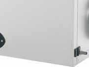
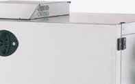
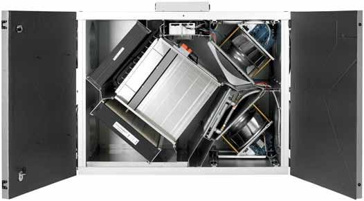
2 Contents VEX140 ( m 3 /h) Technical specifications Capacity curves, Temperature efficiency Sound data Dimensional sketches Water heating coil / Cold water coil... 9 VEX150 ( m 3 /h) Technical specifications Capacity curves, Temperature efficiency Sound data Dimensional sketches Water heating coil / Cold water coil VEX160 (1, m 3 /h) Technical specifications Capacity curves, Temperature efficiency Sound data Dimensional sketches Water heating coil / Cold water coil VEX170 (1, m 3 /h) Technical specifications Capacity curves Temperature efficiency Sound data Dimensional sketches Water heating coil / Cold water coil VEX100 Control system Commissioning and operation Function overview Regulation Advanced standard functions Options Connection to external units Technical specifications, modules itool VEX100 General Cable plans Simplified diagram VEX100 for third party control systems VDI6022 / Split model Outdoor solution / service and maintenance One range - Lots of possibilities The VEX100 unit can be supplied with the air supply on either the left-hand or right-hand side. Spigots can be placed on the sides and the top/bottom as required. Units in the VEX100 series are available as horizontal or vertical units (the VEX140 is also available as a ceiling-mounted unit). Heating coil, water or electric VEX100 units are supplied with integrated post-heating coil, either for water or electricity. Solid construction The VEX100 cabinet is made of aluminium-zinc AZ185 C4 and insulated with 50 mm mineral wool. The VEX 100 can be delivered for fitting outdoors. VDI6022 All EXHAUSTO units have been independently certified in accordance with the German standard, VDI Efficient vibration suppression The fans are suspended on a track system, which makes pulling out and servicing easy. The design of the suspension system, with the motor, impeller and intake together suppresses vibrations very effectively. Base The VEX140, VEX150 and VEX160 are supplied as standard with feet. It is also possible to order a base as extra. The VEX170 is supplied with an integrated base with adjustable feet. Find more information Capacity data and sound data calculations together with principles for connetion of water are based on conditions listed in our website, given under each individual product. The website also allows users to make professional calculations and find prices of the complete system and accessories. Efficient cross-flow heat exchanger The cross-flow heat exchanger is made of aluminium with low pressure loss and a high temperature efficiency. The cross-flow heat exchanger ensures complete separation between the air passages, so no smells or impurities are transfered to the supply air. 2


3 Airflow from 400 to 8400 m 3 /h The VEX140, VEX150 and VEX160 are supplied with round spigots. The VEX170 is supplied with rectangular duct connections, with a Lindab Safe flange system. Please contact us if you need an extra fast delivery time Integrated control The control system is integrated in the VEX100 just above the cross-flow heat exchanger. The control system is grouped together on a pull-out plate for ease of service access. EUROVENT certification The EXHAUSTO air handling units in range VEX100 are all EUROVENT certified. The certificate documents that all technical data provided are third party tested by an individual certification body (EXHAUSTO has been tested and verified by TÜV Nord). This, in terms, means that all data provided by the online calculation tools QuickSelect and EXselect has been verified in tests. EUROVENT Energy labelling The EXHAUSTO air handling units type VEX100 are energy labelled according to EUROVENT guidelines for classification of air handling units. The energy class equals the total energy consumption of the unit at given operation parametres. Find more information on our website Built-in condensation tray The VEX100 range is fitted with a stainless steel condensation tray. EXstream performance All units are supplied with EXHAUSTOs EXstream fan impeller, - the best of its kind in the market when it comes to high efficiency and low sound levels. Compact filters The VEX100 range is supplied with compact (panel) filters. As standard F5 filters are supplied. F7 filters are available as extras. 3
4 VEX140 Technical specifications ( m 3 /h) VEX140 Unit data Built in heating coil* Water heating coil (HCW) Electric heating coil (HCE) Electric heating coil (HCE) Power Consumption - Coil 7.2 kw 14.4 kw Power Consumption - Total 1.6 kw 8.8 kw 16.0 kw Electricity supply 1 x 230 V + NE ~ 50 Hz 3 x 400 V + NE ~ 50 Hz 3 x 400 V + NE ~ 50 Hz Max. phase current 11.2 A** 21.6 A 32.0 A Principal dimensions excluding spigot, cable connections and base (if any) (allow a service distance equal to the depth of the unit in front of the unit) Connection box for control system components Cabinet material Insulation Duct connection Service doors (can be removed) Condensation outlet Filter (outside air and extraction) Bypass Weight, ready to operate unit Weight, unit for internal transport Filter control (not supplied with other control systems) Height = 1,050 mm Length = 1,365 mm Depth = 750 mm Height = 65 mm / free height for service = 500 mm Aluminium zinc, AZ185, Corrosion class C4 50 mm mineral wool dia. 315 mm with horizontal model with vertical model with ceiling model 2 side-hung doors 2 side-hung doors 1 removable door with condensate outlet External/internal dia. = 18/16 mm qty. 1 F5 compact filter 3.7 m 2, 490 x 648 x 96mm qty. 1 F7VDI compact filter 11.5 m 2, 490 x 648 x 96 mm 1, modulating 192 kg 105 kg (excluding doors, fan units and cross-flow heat exchanger) 2, built into connection box Efficient cross flow heat exchanger with aluminium panels Thermal transfer area = 28 m 2 Fan data Fan type EXstream, freely revolving B-impeller Vibration suppression Fans suspended in vibration dampers Motor data (per motor) With integrated control / for third party control Electrical supply (delta/star) 3 x 230 V / 400 V Full load current (delta/star) 3 x 2.6 A / 1.5 A Power consumption 0.55 kw CEMEP-class as EFF1 ***Frequency converter data (2 built in) With integrated control / for third party control Electrical input to frequency converter 1 x 230 V Electrical output from frequency converter 3 x 230 V Current overload protection Built-in Speed control Variable via frequency reg. * Output control and control system/valve components are not supplied for third party control system. ** Power consumption is not sine shaped. ** VEX140 for third party control system can be delivered without a frequeny converter. Accessories MSV140H/V CCW140HK230 CCW140H(L/R) AFC VEX140OD VEX140SPLIT Base for VEX140 horizontal/vertical (adjustable height mm incl. feet) External cold water coil - uninsulated, 39 kg External cold water coil - in cabinet (also available for outdoor fitting, OD), 72 kg Airflow control (required with cooling unit) VEX140 is delivered with a roof and sealed connections for outdoor fitting The VEX140 is available as a split model which can be assembled on site by personnel approved by EXHAUSTO 4
5 VEX140 Capacity curves VEX140-FC - with integrated control VEX140-X - for third party control systems VEX140 A = Capacity curve with F5 filter SFP-curve Operation curves Pressure loss addition with F7 filter Conditions for capacity measurements at our website. To calculate capacity data, we refer you to our product selection program at our website. The energy consumption is divided as 47 % for the exhaust air fan and 53 % for the supply air fan. Capacity curves are measured at the following max frequency: VEX140-FC: 50 Hz VEX140-X: 50 Hz Temperature efficiency Efficiency without condensation according to EN308 t h t = t 2.1 = Temperature efficiency t t 2.1 t 2.1 = Temperature of outdoor air t 2.2 = Temperature of supply air t 1.1 = Temperature of extract air Extract air = 25 C / 30 %RH Outdoor air = 5 C / 50 %RH The temperature efficiency of the VEX unit at different volume flow ratios is shown here, calculated as: The temperature efficiency stated is for dry heat recovery and is increased by condensation. Supply = 0.8 and 1.0 Extract 5
6 VEX140 Sound data VEX140 VEX140 L WA1 - Suction side VEX140 L WA2 - Pressure side Suction side (outdoor/extract air): L W1 = L WA1 + K W L WA1 read Surroundings: L W3 = L WA1 + K W L WA1 read L pa3 = L WA1 +K pa Pressure side (supply/exhaust air): L W2 = L WA2 + K W L WA2 read K W (db) K WA K pa Areas K 2K 4K 8K db(a) db(a) I L W1 II III I L W3 II III K W (db) Areas K 2K 4K 8K I L W2 II III Measurement settings Conditions for sound measurements at our website. To calculate sound data, we refer you to our product selection program at our website. 6
7 A A A-A VEX140 Horizontal/Ceiling - Dimensional sketches - Dimensions in mm VEX140 Horizontal, Left VEX140 Horizontal, Right 223 VEX O 315 O 315 Ø 315 Ø O O Ø Ø * * RD Extract air 1.2. Exhaust air 2.1 Outdoor air 2.2 Supply air Specify the desired spigot position (A or B) when placing your order. 750* 750* All measurements are exclusive feet (12 mm) and base (adjustable from 105 to 135 mm) * Allow a service distance equal to the depth of the unit in front of the unit ** Allow min. 500 mm free height for service RD RD VEX140 Ceiling, Left VEX140 Ceiling, Right ø16/ø18 ø16/ø18 A-A Viewed from the top (the door opens downwards) Viewed from the top (the door opens downwards) O RD O 11 RD A A 7
8 VEX140 Vertical - Dimensional sketches - Dimensions in mm VEX140 VEX140 Vertical, Left O O Ø Ø O 315 O Ø 315 Ø * RD * RD * 634 RD Extract air 1.2. Exhaust air 2.1 Outdoor air 2.2 Supply air Specify the desired spigot position (A or B) when placing your order. All measurements are exclusive feet (12 mm) and base (adjustable from 105 to 135 mm) * Allow a service distance equal to the depth of the unit in front of the unit. ** Allow min. 500 mm free height for service. NB: The connection to the HCW water heating coil is located on the top of the unit. Allow sufficient space for servicing. 8
9 VEX140 Accessories - Water heating / cold water coil We recommend the heating and cold water coil requirements are precisely calculated using the EXselcet product selection tool at our website, which also includes more comprehensive calculation data. VEX140 Operation situation - example of calculated values for the water heating coil VEX140 (1900 m 3 /h / 250 Pa) / HCW140 water heating coil (100 % heat recovery) Outdoor Room Temperature after exchanger HCW output Supply air temperature Water flow Dp HCW K vs Dp K vs Dp Air side [ C / %] [ C / %] [ C] [kw] [ C] [l/h] [kpa] [kpa] [Pa] -12 / / 35 9,9 5, ,2 0,63 16, / / 35 9,1 6, ,5 0,63 19,4 38 Operation situation - example of calculated values for the cold water coil VEX140 (1900 m 3 /h / 250 Pa) / CCW140 cold water coil Outdoor Room CCW cooling output Supply air Water flow Dp CCW K vs Dp K vs Dp Air side [ C / %] [ C/%] [kw] [ C / %] [l/h] [kpa] [kpa] [Pa] 28 / / 50 8,9 18,8 / ,5 30, / / 50 11,3 19,7 / ,2 2,5 49,2 43 Conditions for the calculated examples Conditions HCW Water supply temperature 60 C Water return temperature 40 C Calculated results are accurate to ± 10 % Volume flow ratio 1,0 Heat recovery 100 % NB For frost protection using glycol, the output values in the table above must be reduced by approximately 15-20%. Conditions CCW Water supply temperature 6 C Water return temperature 12 C Calculated results are accurate to ± 10 % Volume flow ratio 1,0 NB The output values in the table above are with a glycol content of 25 %. Dimensional sketches: Uninsulated cold water coil (CCW) NB: In order for the cooling coil to be mounted directly abreast of the supply air spigot of the VEX, the VEX needs to be provided with a base or otherwise elevated. Cold water coil in cabinet - Left Cold water coil in cabinet - Right 9
10 VEX150 Technical specifications ( m 3 /h) Unit data Built in heating coil* Water heating coil (HCW) Electric heating coil (HCE) Electric heating coil (HCE) Power Consumption - Coil 12 kw 18 kw Power Consumption 2.7 kw 14.7 kw 20.7 kw Electricity supply 3 x 400 V + N + PE ~ 50 Hz 3 x 400 V + N + PE ~ 50 Hz 3 x 400 V + N + PE ~ 50 Hz Max. phase current 8.5 A** 25.8 A 34.5 A Max. neutral current 14.0 A VEX150 Principal dimensions excluding spigot, cable connections and base (if any) - (allow a service distance equal to the depth of the unit in front of the unit) Connection box for control system Cabinet material Insulation Duct connection Service doors (can be removed) Condensation outlet Filter (outside air and extraction) Bypass Weight, ready to operate unit Weight for internal transport Filter control (not supplied with other control systems) Height = 1,200 mm Length = 1,600 mm Depth = 835 mm Height = 65 mm / free height for service = 500 mm Aluminium zinc, AZ185, Corrosion class C4 50 mm mineral wool dia. 400 mm with horizontal model 2 side-hung doors with vertical model 2 side-hung doors External/internal dia. = 18/16 mm qty. 1 F5 compact filter 5.0 m 2, 592 x 732 x 96 mm qty. 1 F7VDI compact filter 15.7 m 2, 592 x 732 x 96 mm 1, modulating 285 kg 164 kg (excluding doors, fan units and cross-flow heat exchanger) 2, built into connection box Efficient cross flow heat exchanger with aluminium panels Thermal transfer area = 38 m 2 Fan data Fan type Freely revolving B-impeller Vibration suppression Fans suspended in vibration dampers Motordata (per motor) With integrated control Electrical supply (delta/star) 3 x 230 V / 400 V Full load current (delta/star) 3 x 4.0 A / 2.3 A Power consumption 1.1 kw CEMEP-class EFF1 ***Frequency converter data (2 built in) With integrated control Electrical input to frequency converter 1 x 230 V Electrical output from frequency converter 3 x 230 V Current overload protection Built-in Speed control Variable via frequency reg. * Output control and control system/valve components are not supplied for third party control system. ** Power consumption is assimilated from 2 phases and is not sine shaped. *** VEX150 for third party control system can be delivered without a frequeny converter. Accessories MSV150H/V CCW150HK400 CCW150H(L/R) AFC VEX150OD VEX150SPLIT Base for VEX150 horizontal/vertical (adjustable height mm incl. feet) External cold water coil - uninsulated, 49 kg External cold water coil - in cabinet (also available for outdoor fitting, OD), 87 kg Airflow control (required with cooling unit) VEX150 is delivered with a roof and sealed connections for outdoor fitting The VEX150 is available as a split model which can be assembled on site by personnel approved by EXHAUSTO 10
11 VEX150 Capacity curves VEX150-FC - with integrated control VEX150-X - for third party control systems VEX150 A = Capacity curve with F5 filter SFP-curve Operation curves Pressure loss addition with F7 filter Conditions for capacity measurements at our web site. To calculate capacity data, we refer you to our product selection program at our web site. The energy consumption is divided as 50 % for the exhaust air fan and 50 % for the supply air fan. Capacity curves are measured at the following max frequency: VEX150-FC: 50 Hz VEX150-X: 50 Hz Temperature efficiency Efficiency without condensation according to EN308 t h t = t 2.1 = Temperature efficiency t t 2.1 t 2.1 = Temperature of outdoor air t 2.2 = Temperature of supply air t 1.1 = Temperature of extract air Extract air = 25 C / 30 %RH Outdoor air = 5 C / 50 %RH The temperature efficiency of the VEX unit at different volume flow ratios is shown here, calculated as: The temperature efficiency stated is for dry heat recovery and is increased by condensation. Supply = 0.8 and 1.0 Extract 11
12 VEX150 Sound data VEX150 L WA1 - Suction side VEX150 L WA2 - Pressure side VEX150 Suction side (outdoor/extract air): L W1 = L WA1 + K W L WA1 read Surroundings: L W3 = L WA1 + K W L WA1 read L pa3 = L WA1 +K pa Pressure side (supply/exhaust air): L W2 = L WA2 + K W L WA2 read K W (db) K WA K pa Areas K 2K 4K 8K db(a) db(a) I L W1 II III I L W3 II III K W (db) Areas K 2K 4K 8K I L W2 II III Measurement settings Conditions for sound measurements at our web site. To calculate sound data, we refer you to our product selection program at our web site. 12
13 VEX150 Horizontal - Dimensional sketches - Dimensions in mm VEX150 Horizontal, Left VEX150 Horizontal, Right VEX O O 400 O 400 Ø 400 Ø 400 Ø 400 Ø * RD * 835* RD Extract air 1.2 Exhaust air 2.1 Outdoor air 2.2 Supply air Specify the desired spigot position (A or B) when placing your order. All measurements are exclusive feet (12 mm) and base (adjustable from 105 to 135 mm) * Allow a service distance equal to the depth of the unit in front of the unit. ** Allow min. 500 mm free height for service. 13
14 VEX150 Vertical - Dimensional sketches - Dimensions in mm VEX150 Vertical, Left VEX150 Vertical, Right VEX K K O 122 O Ø Ø O 400 O Ø Ø * RD * 418 RD * RD Extract air 1.2 Exhaust air 2.1 Outdoor air 2.2 Supply air Specify the desired spigot position (A or B) when placing your order. All measurements are exclusive feet (12 mm) and base (adjustable from 105 to 135 mm) * Allow a service distance equal to the depth of the unit in front of the unit. ** Allow min. 500 mm free height for service. NB: The connection to the HCW water heating coil is located on the top of the unit. Allow sufficient space for servicing. 14
15 VEX150 Accessories - Water heating / cold water coil We recommend the heating and cold water coil requirements are precisely calculated using the EXselcet product selection tool at our website, which also includes more comprehensive calculation data. Operation situation - example of calculated values for the water heating coil VEX150 (3125 m 3 /h / 250 Pa) / HCW150 water heating coil (100 % heat recovery) Outdoor Room Temperature and after exchanger HCW output Supply air temperature Water flow Dp HCW K vs Dp K vs Dp Air side [ C / %] [ C / %] [ C] [kw] [ C / %] [l/h] [kpa] [kpa] [Pa] VEX / / 35 9,7 9, ,5 1,6 7, / / 35 8,9 10, ,4 1,6 8,6 45 Operation situation - example of calculated values for the cold water coil VEX150 (3125 m 3 /h / 250 Pa) / CCW150 cold water coil Outdoor Room CCW cooling output Supply air Water flow Dp CCW K vs Dp K vs Dp Air side [ C / %] [ C / %] [kw] [ C / %] [l/h] [kpa] [kpa] [Pa] 28 / / 50 15,7 18,3 / ,4 4,0 37, / / 50 19,6 19,1 / ,9 6,3 23,4 76 Conditions for the calculated examples Conditions HCW Water supply temperature 60 C Water return temperature 40 C Calculated results are accurate to ± 10 % Volume flow ratio 1,0 Heat recovery 100 % NB For frost protection using glycol, the output values in the table above must be reduced by approximately 15-20%. Conditions CCW Water supply temperature 6 C Water return temperature 12 C Calculated results are accurate to ± 10 % Volume flow ratio 1,0 NB The output values in the table above are with a glycol content of 25 %. Dimensional sketches: Uninsulated cold water coil (CCW) NB: In order for the cooling coil to be mounted directly abreast of the supply air spigot of the VEX, the VEX needs to be provided with a base or otherwise elevated. Cold water coil in cabinet - Left Cold water coil in cabinet - Right 15
16 VEX160 - Technical specifications ( m 3 /h) Unit data Built in heating coil* Water heating coil (HCW) Electric heating coil (HCE) Power Consumption - Coil 14.4 kw 21.6 kw 28.8 kw Power consumption 4,8 kw 19,2 kw 26,4 kw 33,6 kw Electricity supply 3 x 400 V + NE ~ 50 Hz 3 x 400 V + NE ~ 50 Hz Max. phase current 15,8 A** 36,6 A 47,0 A 57,4 A Max. neutral current 24,5 A VEX160 Principal dimensions excluding spigot, cable connections and base (if any) (allow a service distance equal to the depth of the unit in front of the unit) Connection box for control system Cabinet material Insulation Duct connection Service doors (can be removed) Condensation outlet Filter (outside air and extraction) Bypass Weight, ready to operate unit Weight for internal transport Filter control (not supplied with other control systems) Height = 1,400 mm Length = 1,820 mm Depth = 940 mm Height = 65 mm / free height for service = 500 mm Aluminium zinc, AZ185, Corrosion class C4 50 mm mineral wool dia. 500 mm with horizontal model 2 side-hung doors with vertical model 2 side-hung doors External/internal dia. = dia. 18/16 mm qty. 2 F5 compact filters 3.6 m 2, 750 x 414 x 96 mm qty. 2 F7 compact filters 11.2 m 2, 750 x 414 x 96 mm 1, modulating 3 kg 202 kg (excluding doors, fan units and cross-flow heat exchanger) 2, built into connection box Efficient cross flow heat exchanger with aluminium panels Thermal transfer area = 50 m 2 Fan data Fan type EXstream, freely revolving B-impeller Vibration suppression Fans suspended in vibration dampers Motor data (per motor) With integrated control / For third party control system Electrical supply (delta/star) 3 x 230 V / 400 V Full load current (delta/star) 3 x 7.8 A / 4.5 A Power consumption 2.2 kw CEMEP-class EFF1 ***Frequency converter data With integrated control / For third party control system Electrical input to frequency converter 1 x 230 V Electrical output from frequency converter 3 x 230 V Current overload protection Built-in Speed control Variable via frequency reg. * Output control and control system/valve components are not supplied for third party control system. ** Power consumption is assimilated from 2 phases and is not sine shaped. *** VEX160 for third party control system can be delivered without a frequeny converter. Accessories MSV160H/V CCW160HK630 CCW160H(L/R) AFC VEX160OD VEX160SPLIT Base for VEX160 horizontal/vertical (adjustable height mm incl. feet) External cold water coil - uninsulated, 54 kg External cold water coil - in cabinet (also available for outdoor fitting, OD), 135 kg Airflow control (required with cooling unit) VEX160 is delivered with a roof and sealed connections for outdoor fitting The VEX160 is available as a split model which can be assembled on site by personnel approved by EXHAUSTO 16
17 VEX160 Capacity curves VEX160-FC - with integrated control VEX160-X - for third party control systems VEX160 A = Capacity curve with F5 filter SFP-curve Operation curves Pressure loss addition with F7 filter Conditions for capacity measurements at our website. To calculate capacity data, we refer you to our product selection program at our web site. The energy consumption is divided as 48 % for the exhaust air fan and 52 % for the supply air fan. Capacity curves are measured at the following max frequency: VEX160-FC: 52.5 Hz VEX160-X: 50.0 Hz Temperature efficiency Efficiency without condensation according to EN308 t h t = t 2.1 = Temperature efficiency t t 2.1 t 2.1 = Temperature of outdoor air t 2.2 = Temperature of supply air t 1.1 = Temperature of extract air Extract air = 25 C / 30 %RH Outdoor air = 5 C / 50 %RH The temperature efficiency of the VEX unit at different volume flow ratios is shown here, calculated as: The temperature efficiency stated is for dry heat recovery and is increased by condensation. Supply = 0.8 and 1.0 Extract 17
18 VEX160 Sound data VEX160 L WA1 - Suction side VEX160 L WA2 - Pressure side VEX160 Suction side (outdoor/extract air): L W1 = L WA1 + K W L WA1 read Surroundings: L W3 = L WA1 + K W L WA1 read L pa3 = L WA1 +K pa Pressure side (supply/exhaust air): L W2 = L WA2 + K W L WA2 read K W (db) K WA K pa Areas K 2K 4K 8K db(a) db(a) I L W1 II III I L W3 II III K W (db) Areas K 2K 4K 8K I L W2 II III Measurement settings Conditions for measurements at our website. To calculate sound data, we refer you to our product selection program at our web site. 18
19 VEX160 Horizontal - Dimensional sketch - Dimensions in mm VEX160 Horizontal, Left VEX160 Horizontal, Right VEX O O 500 O Ø Ø Ø 500 Ø * * RD RD * * RD11512VEX RD11512VEX Extract air 1.2. Exhaust air 2.1 Outdoor air 2.2 Supply air Specify the desired spigot position (A or B) when placing your order. All measurements are exclusive feet (12 mm) and base (adjustable from 105 to 135 mm) * Allow a service distance equal to the depth of the unit in front of the unit. ** Allow min. 500 mm free height for service. 19
20 VEX160 Vertical - Dimensional sketch - Dimensions in mm VEX160 Vertical, Left VEX160 Vertical, Right VEX E O O O 388 O Ø 500 E 388 Ø 500 Ø 500 Ø * RD * 470 RD * RD Extract air 1.2. Exhaust air 2.1 Outdoor air 2.2 Supply air Specify the desired spigot position (A or B) when placing your order. All measurements are exclusive feet (12 mm) and base (adjustable from 105 to 135 mm) * Allow a service distance equal to the depth of the unit in front of the unit. ** Allow min. 500 mm free height for service. NB: The connection to the HCW water heating coil is located on the top of the unit. Allow sufficient space for servicing. 20
21 VEX160 Accessories - Water heating / cold water coil We recommend the heating and cold water coil requirements are precisely calculated using the EXselcet product selection tool at our website, which also includes more comprehensive calculation data. Operation situation - example of calculated values for the water heating coil VEX160 (3870 m 3 /h) / HCW160 water heating coil (100 % heat recovery) Outdoor Room Temperature after exchanger HCW output Supply air temperature Water flow Dp HCW K vs Dp K vs Dp Air side [ C / %] [ C / %] [ C] [kw] [ C] [l/h] [kpa] [kpa] [Pa] -12 / / 35 10,3 11, ,0 1,6 9, / / , ,1 1,6 10,4 42 Operation situation - example of calculated values for the cold water coil VEX160 (3870 m 3 /h) / CCW160 cold water coil Outdoor Room CCW cooling output Supply air Water flow Dp CCW K vs Dp K vs Dp Air side [ C / %] [ C / %] [kw] [ C / %] [l/h] [kpa] [kpa] [Pa] VEX / / 50 20,4 17,7 / ,4 6,3 25, / / 50 25,5 18,4 / ,3 6,3 39,8 41 Conditions for the calculated examples Conditions HCW Water supply temperature 60 C Water return temperature 40 C Calculated results are accurate to ± 10 % Volume flow ratio 1,0 Heat recovery 100 % NB For frost protection using glycol, the output values in the table above must be reduced by approximately 15-20%. Conditions CCW Water supply temperature 6 C Water return temperature 12 C Calculated results are accurate to ± 10 % Volume flow ratio 1,0 NB The output values in the table above are with a glycol content of 25 %. Dimensional sketches: Uninsulated cold water coil (CCW) NB: In order for the cooling coil to be mounted directly abreast of the supply air spigot of the VEX, the VEX needs to be provided with a base or otherwise elevated. Cold water coil in cabinet - Left Cold water coil in cabinet - Right 21
22 VEX170 Technical specifications ( m 3 /h) Aggregatdata Built in heating coil* Water heating coil (HCW) Electric heating coil (HCE) Electric heating coil (HCE) VEX170-1 VEX170-2 VEX170-1 VEX170-2 Power Consumption - Coil 31,2 kw 46,8 kw 31,2 kw 46,8 kw Power Consumption - Total 5,6 kw 8,6 kw 36,8 kw 52,4 kw 39,8 kw 55,4 kw Electricity supply 3 x 400 V + N + PE ~ 50 Hz 3 x 400 V + N + PE ~ 50 Hz 3 x 400 V + N + PE ~ 50 Hz Max. phase current 17,0 A** 18,5 A,0 A 84,5 A 63,5 A 86,0 A Max. neutral current 24,0 A VEX170 Principal dimensions excluding spigot and cable connections (allow a service distance equal to the depth of the unit in front of the unit) Connection box for control system Cabinet material Insulation Duct connection (H x W) Service doors (can be removed) Condensation outlet Filter (outside air and extraction) Bypass Weight, ready to operate unit Weight, unit for internal transport Filter control (not supplied with other control systems) Height = 1,800 mm Length = 2,200 mm Depth = 1,240 mm Height = 65 mm / free height for service = 500 mm Aluminium zinc, AZ185, Corrosion class C4 50 mm mineral wool 500 x 600 mm 2 side-hung doors External/internal dia. = 20/18 mm qty. 2 F5 compact filters 5.6 m 2, 850 x 564 x 96 mm qty. 2 F7VDI compact filters 17.3 m 2, 850 x 564 x 96 mm 1, modulating VEX170-1 = 646 kg / VEX170-2 = 6 kg 411 kg (excluding doors, fan units and cross-flow heat exchanger) 2, built into connection box Efficient cross flow heat exchanger with aluminium panels Thermal transfer area = 76 m 2 Fan data Fan type Freely revolving B-impeller Vibration suppression Fans suspended in vibration dampers Motor data (per motor) VEX170-1 with integrated / for third party control system VEX170-2 with integrated / for third party control system Electrical supply (delta/star) 3 x 230 V / 400 V 3 x 230 V / 400 V Full load current (delta/star) 3 x 10.6 A / 6.1 A 3 x 13.1 A / 7.6 A Power consumption 3.0 kw 4.0 kw CEMEP-class EFF1 EFF1 ***Frequency converter data (qty. 2 built-in) VEX170-1 with integrated / for third party control system VEX170-2 with integrated / for third party control system Electrical input to freq. conv. 1 x 230 V 3 x 400 V Electrical output from freq. conv. 3 x 230 V 3 x 400 V Current overload protection Built-in Built-in Speed control Variable via frequency reg. Variable via frequency reg. * Output control and control system/valve components are not supplied for third party control system. ** Power consumption is assimilated from 2 phases and is not sine shaped. *** VEX170-2 for third party control system can be delivered without a frequeny converter. Accessories CCW170HK1000 CCW170H(L/R) AFC VEX170OD VEX170SPLIT External cold water coil - uninsulated, 72 kg External cold water coil - in cabinet (also available for outdoor fitting, OD), 165 kg Airflow control (required with cooling unit) VEX170 is delivered with a roof and sealed connections for outdoor fitting The VEX170 is available as a split model which can be assembled on site by personnel approved by EXHAUSTO 22
23 VEX170 Capacity curves VEX170-1-FC - with integrated control A = Capacity curve with F5 filter SFP-curve Operating curves Pressure loss addition with F7 filter Conditions for capacity measurements at our website. The energy consumption is divided as follows: VEX170-1FC: 49 % for the exhaust air fan 51 % for the supply air fan VEX170-2FC: 50 % for the exhaust air fan 50 % for the supply air fan To calculate capacity data, we refer you to our product selection program at our web site. Capacity curves are measured at the following max. frequency: VEX170-1-FC: 41.5 Hz VEX170-2-FC: 49.0 Hz VEX170-2-X: 50.0 Hz If the VEX170-2-X is supplied with a frequency converter, the motor can be loaded with up to 49.0Hz, and the capacity curve for the VEX170-2-FC can be used. VEX170 VEX170-2-FC - with integrated control VEX170-2-X - for third party control systems 23
24 VEX170 Temperature efficiency Efficiency without condensation according to EN308 t h t = t 2.1 = Temperature efficiency t t 2.1 t 2.1 = Temperature of outdoor air t 2.2 = Temperature of supply air t 1.1 = Temperature of extract air Extract air = 25 C / 30 %RH Outdoor air = 5 C / 50 %RH VEX170 The temperature efficiency of the VEX unit at different volume flow ratios is shown here, calculated as: Supply = 0.8 and 1.0 Extract The temperature efficiency stated is for dry heat recovery and is increased by condensation. 24
25 VEX170-1 Sound data VEX170-1 L WA1 - Suction side VEX170-1 L WA2 - Pressure side VEX170 Suction side (outdoor/extract air): L W1 = L WA1 + K W L WA1 read Surroundings: L W3 = L WA1 + K W L WA1 read L pa3 = L WA1 +K pa Pressure side (supply/exhaust air): L W2 = L WA2 + K W L WA2 read K W (db) K WA K pa Areas K 2K 4K 8K db(a) db(a) I L W1 II III I L W3 II III K W (db) Areas K 2K 4K 8K I L W2 II III Measurement settings Conditions for sound measurements at our web site. To calculate sound data, we refer you to our product selection program at our web site. 25
26 VEX170-2 Sound data VEX170-2 L WA1 - Suction side VEX170-2 L WA2 - Pressure side VEX170 Suction side (outdoor/extract air): L W1 = L WA1 + K W L WA1 read Surroundings: L W3 = L WA1 + K W L WA1 read L pa3 = L WA1 +K pa Pressure side (supply/exhaust air): L W2 = L WA2 + K W L WA2 read K W (db) K WA K pa Areas K 2K 4K 8K db(a) db(a) I L W1 II III I L W3 II III K W (db) Areas K 2K 4K 8K I L W2 II III Measurement settings Conditions for sound measurements at our web site. To calculate sound data, we refer you to our product selection program at our web site. 26
27 VEX170 Horizontal - Dimensional sketch - Dimensions in mm VEX170 Horizontal, Left VEX170 Horizontal, Right VEX * RD * * RD * RD Extract air 1.2. Exhaust air 2.1 Outdoor air 2.2 Supply air Specify the desired spigot position (A or B) when placing your order. * Allow a service distance equal to the depth of the unit in front of the unit. ** Allow min. 200 mm free height for service. The height (1800 mm) is when the feet of the base are set at standard length. The feet are adjustable which makes the height variable within the interval of mm. NB: The water trap on the condensation outlet requires a certain amount of free height a height of 1800 mm is adequate. 27
28 VEX170-1 Accessories - Water heating / cold water coil We recommend the heating and cold water coil requirements are precisely calculated using the EXselcet product selection tool at our website, which also includes more comprehensive calculation data. Operation situation - example of calculated values for the water heating coil VEX170-1 (5760 m 3 /h / 250 Pa) / HCW170 water heating coil (100 % heat recovery) Outdoor Room Temperature after exchanger HCW output Supply air temperature Water flow Dp HCW K vs Dp K vs Dp Air side [ C / %] [ C / %] [ C] [kw] [ C] [l/h] [kpa] [kpa] [Pa] -12 / / , ,5 2,5 9, / / 35 9,6 18, ,6 2,5 10,3 38 Operation situation - example of calculated values for the cold water coil VEX170-1 (5760 m 3 /h / 250 Pa) / CCW170 cold water coil Outdoor Room CCW cooling output Supply air Water flow Dp CCW K vs Dp K vs Dp Air side [ C / %] [ C / %] [kw] [ C / %] [l/h] [kpa] [kpa] [Pa] 28 / / 50 37,1 16,3 / ,3 10,0 33,4 40 VEX / / 50 44,1 17,2 / ,9 10,0 47,2 40 VEX170-2 Accessories - Water heating / cold water coil Operation situation - example of calculated values for the water heating coil VEX170-2 (8000 m 3 /h) / HCW170 water heating coil (100 % heat recovery) Outdoor Room Temperature after exchanger HCW output Supply air temperature Water flow Dp HCW K vs Dp K vs Dp Air side [ C / %] [ C / %] [ C] [kw] [ C] [l/h] [kpa] [kpa] [Pa] -12 / / 35 9,6 24, ,6 2,5 18, / / 35 9,1 25, ,7 4,0 8,0 70 Operation situation - example of calculated values for the cold water coil VEX170-2 (8000 m 3 /h / 250 Pa) / CCW170 cold water coil Outdoor Room CCW cooling output Supply air Water flow Dp CCW K vs Dp K vs Dp Air side [ C / %] [ C / %] [kw] [ C / %] [l/h] [kpa] [kpa] [Pa] 28 / / 50 47,2 17,7 / ,4 10,0 54, / / 50 56,1 18,7 / ,6 10,0 76,3 69 Conditions for the calculated examples Conditions HCW Water supply temperature 60 C Water return temperature 40 C Calculated results are accurate to ± 10 % Volume flow ratio 1,0 Heat recovery 100 % NB For frost protection using glycol, the output values in the table above must be reduced by approximately 15-20%. Conditions CCW Water supply temperature 6 C Water return temperature 12 C Calculated results are accurate to ± 10 % Volume flow ratio 1,0 NB The output values in the table above are with a glycol content of 25 %. 28
29 VEX170 Accessories - Dimensional sketches - Dimensions in mm Uninsulated cold water coil (CCW) NB: In order for the cooling coil to be mounted directly abreast of the supply air spigot of the VEX, the VEX needs to be provided with a base or otherwise elevated. Cold water coil in cabinet - Left Cold water coil in cabinet - Right VEX170 29


 Indicator lamp OFF Standby Economy Comfort Switch/ button Simple")
30 VEX100 Control system - Simple to operate and with an option for advanced control Behind the simple user interface, the advanced VEX100 control ensures the efficient and economic operation of the air-handling unit. The control can also be adapted to the daily rhythms of the location, whether it is a school, office or meeting room. The key functions are: Simple operation using the DISPLAY and/or TOUCH-panel 3 levels of operation of the control ensure that all users can operate the unit in the best way 3 operating levels adapt the ventilation to the actual requirement: Economy / Stand-by / Comfort Built-in weekly timer with graphic display Option for connection to DDC unit via LONWORKS as standard The TOUCH panel can be set to different functions Many functions are standard, e.g. night-time cooling DISPLAY panel Day Daily timer Operating level The settings that can be adjusted are marked with an asterix (*) Indicator lamp OFF Standby Economy Comfort Switch/ button Simple operation of the VEX100 using the DISPLAY panel can be done at three levels: Operating mode Person Operating situations using the DISPLAY panel User mode Users in the room, office staff, for example. Setting the airflow and the temperature, as well as reading information about the operation of the unit. Technician mode Responsible for the operation of the unit Adjusting the daily operation (timer, temperature limits and similar). All settings can be read, but only the settings in the menus marked with an asterix can be adjusted Specialist mode EXHAUSTO s fitters and other specially trained personnel All settings can be adjusted Operating levels Operating level Operating situation Airflow Temperature Off (OFF) Stop unit No ventilation No heat control Economy (ECO) Night operation Step 1 (low airflow) Larger permissible temp. deviation* Standby (SBY) Basic ventilation Step 1 (low airflow) Small temp. deviation permitted* Comfort (COM) Comfort ventilation Steps 1-10 (large airflow) Precise temperature* * permitted temp. deviation can be adjusted 30


31 VEX100 Control - Commissioning and operation The VEX100 control system allows control at 3 levels of operation as well as stopping the unit. The changes between the different levels can be carried out automatically via the built-in timer in the DISPLAY panel, which also contains a weekly planner with a graphic program display. Manual control is via the DISPLAY or TOUCH panel. Alarms and information about deviations in operation can be read on the DISPLAY panel, which also allows the possibility to see an error list of the last 10 alarms, with dates and times. TOUCH-panel Indicator light The TOUCH panel can be set to the required function at the rear of the panel. Up to 8 TOUCH panels can be linked to the unit. These only need to have their own address, which is also set at the rear of the panel on installation. Use the DISPLAY panel to set the time on the timer function. De-activation of function Activation of function The TOUCH panel can be set on installation to one of the following four functions: Function Setting Positioning, ex. Timer function Overrides to comfort level for pre-set time. Meeting room Timer function, master Manual function Manual function, master Overrides to comfort level for a pre-set time. Resets other panels Manual change of level of operation, either for start ing or stopping the unit (outside the timer program) or for temporarily changing the level of operation until the timer changes As manual function. Resets all other panels to zero. Typically centrally located, for example in reception Lounge with 24 hour ventilation Same but with requirement for corr. function Holiday function. Stops unit until the next activation of the panel. Centrally located, for example in reception Integrated control The connection box is integrated in the VEX. It is located on top of the VEX for easy access. The filter controls are placed in the box, and the DISPLAY panel is factory fitted and is inside the box on delivery. The DISPLAY panel can be positioned as required. 31
32 VEX100 Control system - function overview The functions of the control are described in the table below. There are more detailed descriptions of selected functions on the following pages. Function / component Filter control Modulating bypass Temperature sensors Overheating protection (electric heating coil) - 70/90 C Description Pressure sensors for monitoring the pressure drop across the filter - alarm for a fall more than the value set (due to dirt) Leads the outdoor air out of the cross-flow heat exchanger depending on the need for heat recovery in order to maintain the desired supply air temperature 1) In the inlet valve for measuring/control of the room temperature 2) In the exhaust spigot for controlling the de-icing function 3) In the outdoor air spigot for outdoor temperature compensation and night-time cooling 4) In the inlet valve for measuring/control of the supply air temperature 5) To the exhaust air ducts (external) 6) In a given room to control the room temperature (alternative to 1) 7) On the exhaust pipe from the water heating coil to keep the water heating coil warm and to protect it from frost 8) For frost protection of the external piping for the water heating coil At temperatures above 70/90 C the electricity supply to the heating coil is cut off - automatic reset at 70 C / manual reset at 90 C Standard Extra Overheating protection (fan motor) If there is a danger of the motor overheating the unit will shut off - manual reset Fire thermostat - 40/50/70 C Closing damper, outside air, (required with water heating coil) Closing damper - exhaust The unit will be disconnected at temperatures above 40/50/70 C - manual reset of the thermostat - located in the supply air or extract air duct. The unit can be set so that in case of fire it will: 1) Stop completely, or 2) Stop supply air but continue forced extract air, or 3) Continue forced supply and extract air The damper is fitted in the outdoor air inlet duct - it shuts when the unit stops - available with a spring-return motor Damper is fitted in the exhaust duct - it shuts when the unit stops - available with a spring-return motor VEX100 Control system Modulating motor valve for water Regulation of supply air temperature The valve variably opens and closes the water supply to the water heating coil as required The supply air temperature is regulated according to set points with option for compensation from the outdoor air Regulation of room temperature The room temperature is regulated according to set points with an option for summer compensation and setting a maximum room temperature De-frost function De-icing via reduced supply air flow or via a bypass Night-time cooling The unit can be set to start at night to cool the building DISPLAY panel Panel for operation at user, technician and specialist level (see next page) Weekly timer For setting the required times for changing between operating levels: stop, economy, standby, comfort TOUCH panel Option for 5 functions (see previous page) LONWORKS Communication Bus communication for monitoring and/or control of the unit (connection to DDC) Cooling control Control signal from the cooling system (EON-XCU2) Circulation pump control Control of circulation pump for water heating coil CO2 sensor on-demand control Regulate the airflow according to the measured CO2 content of the air Humidity sensor for on-demand control Regulates the air volume on the basis of the relative air measured Icing detector Starts de-icing according to the pressure loss across the cross-flow heat exchanger (requires airflow control) Constant pressure regulation Possible for both extract and supply air Measurement socket for airflow measurement Measuring points for pressure, temperature and air-flow Pressure measuring points for determining the airflow Pressure and temperature measuring points according to the VENT arrangement Airflow control (required with cooling unit) Sensors for measurement and control of constant airflow Alarm relay Change-over relay 32
33 VEX100 Control system - Standard functions Regulation The VEX100 control system meets all the control requirements for maintaining a perfect indoor climate. As standard there is an option to control the VEX100 from the DDC unit via LONWORKS or EXHAUSTO s itool Internet server, which gives a direct connection to the VEX from your PC. Several operating levels - save energy The control system features a range of options designed to save energy when operating in economy and standby modes (see fig. 1). Regulation principles The control system controls the built-in heating coil (water or electric) in sequence with a bypass and a cooling unit, if used, (fig. 2). The control offers options for regulating the room temperature or the supply air. Fig. 1: Example of temperature set point for comfort, standby and economy operation T-Comfort max. 40 C T-Comfort 22 C T-Comfort min. 10 C (22+1 = 23 C) Menu 671 Recovery T-Comfort (+/- 1K) (22-1 = 21 C) Cooling requirement (22+3 = 25 C) Menu 672 T-Standby (+/- 3K) (22-3 = 19 C) Heating requirement Menu 673 T-Cool Economy (e.g. 28 C) Menu 674 T-Heat Economy (e.g. 16 C) Comfort Standby Economy The control system regulates the damper (heat recovery effect) to maintain the required T-comfort of 22 C. With T-comfort, it is set to how close to the 22 C temperature is required, either heating (22-1 = 21 C) or cooling (22+1 = 23 C). Standby operation with low airflow (step1) gives the option to achieve even greater savings by setting to T-standby. As shown above, this is achieved with heating 22-3=19 C, and with cooling 22+3 = 25 C when the unit is in standby. With economy heating the setting is an absolute temperature, such as 16 C for heating and 30 C for cooling. This allows the option to lower the temperature during heating and that the cooling unit only starts when the temperature rises above 30 C. With the control of the cooling unit there is also an option to set the max. temperature difference T between the room and supply air temperature. VEX100 Control system Fig. 2: Heat, bypass and cooling control 33
34 VEX100 control system - Standard functions Advanced standard functions Room temperature control Room temperature is controlled by means of the built-in temperature sensor or an external room sensor. When regulating the room temperature there is also an option for summer compensation (fig. 3). When summer compensation is selected, the set point for the desired room temperature will increase in line with the outside temperature. This avoids an unpleasant cold shock because of too great a difference between the indoor and outdoor temperature, and also saves energy. Supply air regulation When regulating the supply air temperature there is an option for outdoor compensation (fig 4). When this is selected the set point for the supply air temperature is lowered in summer (and possibly raised in winter) and so the supply air temperature is compensated on the basis of the outdoor temperature. The temperature is compensated by the built-in temperature sensor in the outside outdoor air spigot. Fig. 3: Regulation of room temperature with summer compensation Required room temperature = 20 C Fig. 4: Control of supply air tem perature with outdoor air compensation Required supply air temperature = 20 C Max. supply air temperature = 35 C Min. supply air temperature = 10 C VEX100 Control system Additional standard functions Night-time cooling Without any extra equipment, night-time cooling can be selected, which functions without any cooling unit being attached. In buildings with large mass (weight) the comfort in summer can be improved by cooling the building with cool outdoor air at night. Night-time cooling is particularly suitable for offices, institutions, etc. where people do not work at night. Night-time cooling can only be activated during the summer and when the unit is not in comfort operating mode. It is possible to set a temperature and a time for night-time cooling. Frost protection of water heating coils Frost protection of water heating coils is controlled by temperature sensors on the return pipe. If during operation the temperature falls under the set temperature, the unit stops. When the unit stops a heat retention function starts which keeps the water in the return pipe at a set temperature. This minimises the risk of frost in the heating coil and the unit is ready to start immediately even when the temperatures outside are low. There is also an built-in control to run the circulation pump during periods when heating is not required. 34
35 VEX100 control system - Standard functions Additional standard functions - continued Starting the unit On starting the unit always runs for a few minutes with extraction to warm up the cross-flow heat exchanger before the supply air is started. Run on with electric heating coil With an electric heating coil there is a built-in run on, so the fan runs for three minutes after the unit stops. During these 3 min. the heating coil is disconnected. Outside compensation of airflow The control system has a built-in function for reducing the airflow when the outdoor temperature is falling. The temperature is measured in the outdoor air spigot. De-icing function The de-icing function is activated on the basis of a set temperature measured at the exhaust spigot. When the function is activated, the supply airflow is reduced to 1 step, or bypass de-icing takes place. Bypass de-icing is carried out through the following procedure: The control system registers icing on the cross-flow heat exchanger The bypass damper opens slowly (10% per minute). The normal temperature control system will deal with opening the motor valve and supplying post-heat. Filter control There are built-in filter controls in the unit. These are located in the connection box and can easily be set during operation. If a filter needs to be changed a yellow lamp lights up on the DISPLAY and TOUCH-panel and an entry is made in the alarm list. VEX100 Control system - Options In addition to the numerous standard functions there are also options, such as: VEX100 Control system Airflow control to maintain the airflow rate even if the filters are dirty etc. The airflow is shown in the DISPLAY panel. Airflow control is a requirement with a cooling unit in order to monitor the minimum airflow Detecting ice in the cross-flow heat exchanger on the basis of pressure measurement (requires airflow control) The functions listed above can be fitted to the VEX unit to order. Example of control of airflow with CO 2 and/or override When the automatic control system is operative, this function can be used to increase the required airflow when the CO 2 / concentration in the room increases 35
36 VEX100 Control system - Options Example of ZONE control with modulating damper and constant pressure regulation Constant pressure regulation of the flow of extract and/or supply air Possibility LonWorks for DDC EON EON-ZONE EON-ZONE CO 2 sensor for overriding the fan speed DISPLAY panel with built-in clock 230VAC 24VDC= Humidity sensor (RH) for overriding the fan speed CO 2 RH ZONE control of local on/off damper via, for example, manual activation, PIR sensor (Passive Infrared Receiver or hygrostat on/off) The VEX 100 range ZONE control of local modulating damper (0-10V control voltage) via, for example CO 2 or sensor XTP EON-PRESSURE VEX100 Control system VEX100 Control system - Connection to external units Connection to external units External units operate via the EXHAUSTO Operating Network (EON), which is a bus-based network. With the start and initial adjustment of the unit the control system checks what units are linked to the network. During day-to-day operation, the control system monitors all the units that are operating and provides information about any errors that may occur. The units to be linked to the network should be positioned in a structured manner, like a daisy chain. The signal cable is a 4-wire cable (2x2x0.6mm) where 2 wires are used for the electric current (24VDC) and 2 are used for communication. Service can be carried out quickly without affecting the other units in the network, as one module can be removed without breaking the connection to the others (the cable is looped onto plug terminals). For servicing, an extra DISPLAY panel can be linked to the VEX. This has to be done in specialist mode and overrides the normal operation of the unit. 4 DISPLAY Panel Up to 20 units Max. 50 m cable connection 4 4 CO2 - sensor Pressure sensor 4 TOUCH Panel 4 TOUCH Panel Max. 8 pcs RD11489GB-01 36
37 VEX100 Control system - Technical specifications, modules Protection class DISPLAY panel DISPLAY panel TOUCH panel IP20 IP ,2 EON-modules IP54 itool IP54 VEX100 Control system 85 Time resolution in the timer function 10 min. Precision, timer function 1 sec./day Timer in TOUCH panel Precision of heat control LON-network transceiver Relay contact for the circulation pump min K with stationary operation FTT-10 A 250 V, 2 A EON-DISPLAY - 8 TOUCH panel ZONE module Control signal, AI/AO 0-10 V Control signal for DI Potential free 85 Relay contact, DO 250V, 8A (AC1) CO 2 sensor Control signal, AO 0-10 V Measurement area ppm EON-TOUCH-8 Precision ppm (at 25 C) Humidity sensor Control signal, AO 0-10 V Measurement area 5-95% RH Precision + - 3% RH (30-70% RH) PIR sensor Perspective, horizontal 90 VEX100 Control system Range 6 m Cut-out delay 10 min. 37


38 itool connection to the ventilation unit via your PC or mobile Conveniently monitor and control VEX units Option to log data Option to notify alarms via itool is an Internet server that uses the TCP/IP protocol to provide a connection between a ventilation system and the Internet. This allows monitoring and control of the unit from a computer via the Internet or a local area network. itool can be connected to up to five EXHAUSTO VEX100 air handling units and 15 MAC11-22 constant pressure regulators for controlling extractor fans. These products are equipped with LON communication, which automatically connects to itool. You can use itool without any special programs or training. The interface is via your browser and the Adobe SVG viewer. itool Basic version for connection direct to a PC, intranet or broadband modem. itool can also be connected to a standard modem or ISDN, but is not sent automatically in these cases. itool MOBILE Choose this solution if you want to notify alarms via text messages. It is possible to establish a fixed connection to the GSM network s GPRS protocol. However, GPRS must be assigned a fixed IP address in this case Getting started with itool The only installation needed is a cable connection between the ventilation unit and the itool box. From here, it is simply a matter of running cables to an Internet socket to set up connection with the Internet or a different network. How to use itool You do not need any special programs or specialist training to use itool. All you need is an Internet browser and Acrobat Reader. itool automatically logs data every 5 minutes, and you can store data for up to a month. 38
39 Visit our website Tel NOINOIOIN Connection to DDC unit CTS connection via LON VEX100 Control system can be connected to LONWORKS, which is an open communication system with standardised communication exchange. LONWORKS is integrated in the control system, and LON-Mark compatibility is assured in the relevant areas. A standard network variable is used (SNVT) to transfer all the information allowing a connection to most DDC units and other control systems.the control system has a built-in communication interface to LON-network with a transceiver (FTT-10 A). The transceiver functions as a transmitter/receiver between the control (neuron chip) and the LONWORKS network The VEX100 control system can power LONWORKS units with a max of 250 ma. EXHAUSTO has tested LON communication in partnership with the leading DDC suppliers in Denmark. CTS connection via Modbus RTU RS485 itool can be used as a gateway to CTS systems supporting Modbus. itool allows various Modbus variables to be set: addresses, baud rate, parity, etc. itool data It is possible to read or set the most common VEX100 control variables. PC Pentium II, 500MHz, 64 MB RAM with modem or Ethernet 10/100TbaseT network card Software Explorer 5.5 or higher, Adobe SVG-viewer Data storage program Excel XP or similar to process XML data Network cable m depending on cable type and installation Max. ambient temp. 0 C 40 C Network connection RS232 Analogue modem, ISDN or 0-modem cable Ethernet 10/100Tbase TCP/IP netværksport ADSL, Broadband, Ethernet LAN e GSM modem (only for itool-mobile) GSM or GPRS connection allows SMS communication Connected control systems Five VEX100 and 15 MAC11-22 Air handling units and constant pressure regulators VEX100 Control system Visit our website e Demonstration of itool Visit our website Visit our website for more information about itool. Here, you can also see a demonstration of how itool functions in practice. e Tel Find out more about itool Would you like to find out more about itool or talk to a consultant? If so, contact the EXHAUSTO sales department we are ready and waiting to help you with your itool questions! 39
40 Cable plans Cable dimensioning All cable and fuse sizes should be understood as minimum requirements. The electrician installing the unit is respons ible for ensuring that all sizes used are compatible with current legislation and regulations. Installing the earth leak circuit breakers If earth leak circuit breakers are fitted in the installation, they must be of a type that meets the following requirements: VEX140 / VEX150 / VEX160 / VEX170-1: PFI-breaker type A in regard to EN 61008, which break the circuit when they register vagrant current with DC content (pulsating DC) VEX170-2: PFI-breaker type B in regard to EN 61008, which break the circuit when they register vagrant current with DC content (pulsating DC) A current leakage of up to 300mA can be expected. Cable plan - VEX100 with water heating coil (HCW) * Not supplied by EXHAUSTO VEX100 General Size Power consumption (max. phase current) (A) Max. neutral current (A) Supply Voltage (V) Fuses (AgL) F1* Cable** W1/W2 VEX140-FC 11,2 1 x N + PE 13 3G1,5 VEX150-FC 8,5 14,0 3 x N + PE 13 5G1,5* VEX160-FC 15,8 24,5 3 x N + PE 20 5G4,0* VEX170-1-FC 17,0 24,0 3 x N + PE 20 5G4,0* VEX170-2-FC 18,5 3 x N + PE 25 5G2,5 * Dimensioning of the neutral conductor. The current assimilated in the two frequency converters is not a pure sine wave. The neutral conductor must be dimensioned to ensure that it can cope with a load. ** Not supplied by EXHAUSTO 40
41 Cable plan - VEX100 with electrical heating coil (HCE) * Not supplied by EXHAUSTO ** = F2-F6 number depends on size of VEX *** = W3-W7 2-5 cables depending on size of VEX Size VEX140-FC VEX150-FC VEX160-FC VEX170-1-FC VEX170-2-FC Output (kw) Power consumption (max. phase current) (A) Fans Heating coil Supply Total Voltage F1 F2 (V) VENT Fuses (AgL) ** fans/heating coil F3 F4 F5 F6 W1/W2 W3 VENT Cables** W4 W5 W6 W7 7,2 11,2 10,4 21,6 3x400+N+PE G4,0 3G1,5 4G2,5 14,4 11,2 20,8 32 3x400+N+PE G6,0 3G1,5 4G2,5 4G2,5 12 8,5 17,3 25,8 3x400+N+PE G6,0 4G1,5* 4G2,5 4G2,5 18 8, ,5 3x400+N+PE G10 4G1,5* 4G2,5 4G2,5 4G2,5 14,4 15,8 20,8 36,6 3x400+N+PE G10 4G4,0* 4G2,5 4G2,5 21,6 15,8 31,2 47 3x400+N+PE G16 4G4,0* 4G2,5 4G2,5 4G2,5 28,8 15,8 41,6 57,4 3x400+N+PE G25 4G4,0* 4G2,5 4G2,5 4G2,5 4G2,5 31, x400+N+PE G25 4G4,0* 4G2,5 4G2,5 4G6,0 46, ,5 84,5 3x400+N+PE G35 4G4,0* 4G2,5 4G2,5 4G6,0 4G6,0 31,2 18, ,5 3x400+N+PE G25 4G2,5 4G2,5 4G2,5 4G6,0 46,8 18,5 67,5 86 3x400+N+PE G35 4G2,5 4G2,5 4G2,5 4G6,0 4G6,0 * Dimensioning of the neutral conductor. The current assimilated in the two frequency converters is not a pure sine wave. The neutral conductor must be dimensioned to ensure that it can cope with a load. ** Not supplied by EXHAUSTO Cable plan - accessories VEX100 General 41
42 Simplified diagrams The VEX100 is supplied with components fitted in the unit or for fitting in the duct system and in the appropriate room. The layout drawings show the components that can be fitted to VEX100 air handling units with water and electric heating coils. The table lists the components for the VEX100. The table shows whether the components are connected via the network (EON) and whether they are standard or extra components which need to be ordered separately. Abriviation Description Via EON* l Standard m Extra AFC1/AFC2 Airflow control (required with cooling unit) m BT40/BT50/BT70 Fire thermostat 40 C or 50 C and 70 C m CO2 CO 2 sensor X m DISPLAY DISPLAY panel X l GV1 Bypass with motor l HCE Electric heating coil (Heating Coil Electric) X m HCW Water heating coil (Heating Coil Water) X m LS Closing damper, exhaust air m LS Closing damper, outdoor air (requirement for water heating coil) m MVM Motor valve, water heating coil (HCW) X l PDS1 Filter control, extract air l PDS2 Filter control, outdoor air l PDT1 Icing detector, defrost m PRESSURE Pressure sensor for constant pressure control X m RH Humidity sensor X m TE11 Temperature sensor, extract - spigot 1.1 l TE12 Temperature sensor, exhaust - spigot 1.2 l TE21 Temperature sensor, outdoor air - spigot 2.1 l TE22 Temperature sensor, supply air - spigot 2.2 l TOUCH TOUCH panel X m TS-DUCT Temperature sensor, extract air duct (external) X m VEX100 General TS-HCW Temperature sensor, return pipe from water heating coil (HCW) l TS-MVM Temperature sensor, external piping (HCW) X m TS-ROOM Temperature sensor, room X m TSA1 Overheating, exhaust motor l TSA2 Overheating supply air motor l TSA70/TSA90 Overheating thermostat 70 C and 90 C (HCE) l XCU2 Cooling control X m * = EON, EXHAUSTO Operating Network 42
43 Simplified diagram - VEX100 with water heating coil (HCW) and VEX100 control system Simplified diagram - VEX100 with electrical heating coil (HCE) and VEX100 control system VEX100 General 43
44 VEX100 for third party control systems Freedom to choose As alternatives all VEX100 units offer a solution with a different control system. VEX100 for third party control system can be delivered with or without frequency converter. This allows integrating the VEX100 units with a control system from other suppliers. The solution is optimised for simple and efficient integration on site. The following table shows which components are included in a VEX100 for another control. The connections are all made at the same place To make the fitting and integration as simple as possible, all the connections are collected on a terminal board. The motor cables, connections to the electric heating coil, hoses for flow volume measurement and pressure loss are led to the terminal board. The bypass-motors are tested and fitted, and the connections led to the terminal board. The water heating coil is fitted and the connections are led out through the cabinet. Capacity The solution for third party control system is supplied with the same highly efficient motor as the VEX100 units with integrated control. VEX170 with motor size 1 can only be delivered with frequency converter. Abriviation Description l Standard m Extra AFC Airflow control - Silicone tubes for measurement are fitted l M 2 motors / fans l FC Frequency converters, installed and programmed m GV Bypass with motor l HCW Water heating coil (Heating Coil Water) l LS Closing damper, exhaust air m LS Closing damper, outdoor air (requirement for water heating coil) m PDS Filter control - Silicone tubes for measurement are fitted l - Connection box with electric connections and air hoses l Simplified diagram VEX100 General - VEX100 with water heating coil (HCW) - for third party control system 44
45 Electrical connection for third party control system VEX100 for third party control system with FC Size Supply voltage (V) Dimensioning power consumption (A) (max. phase current) VEX140 FAA FC 1 x 230 V + N + PE ~ 50 Hz 11,1 Dimensioning max. neutral curent (A) VEX150 FAA FC 3 x 400 V + N + PE ~ 50 Hz 8 13,5 VEX160 FAA FC 3 x 400 V + N + PE ~ 50 Hz 15,5 24,3 VEX170-1 FAA FC 3 x 400 V + N + PE ~ 50 Hz 18,5 25,5 VEX170-2 FAA FC 3 x 400 V + N + PE ~ 50 Hz 18,8 VEX100 for third party control system without FC Size VEX140 FAA VEX150 FAA VEX160 FAA VEX170 FAA Supply voltage (V) Dimensioning power consumption (A) (max. phase current) 3 x 230 V + PE ~ 50 Hz 5,2 3 x 400 V + PE ~ 50 Hz 3 3 x 230 V + PE ~ 50 Hz 8 3 x 400 V + PE ~ 50 Hz 4,6 3 x 230 V + PE ~ 50 Hz 15,6 3 x 400 V + PE ~ 50 Hz 9 3 x 230 V + PE ~ 50 Hz 26,2 3 x 400 V + PE ~ 50 Hz 15,2 The motors are wired for 3 x 400 V from the factory. VEX100 General 45
 in accordance with VDI 6022.")
46 Guaranteed air quality - VDI6022 To ensure that the VEX100 meets the rigorous hygiene requirements that currently apply to ventilation equipment, the unit has been tested and approved by ILH Berlin (Institut für Lufthygiene) in accordance with VDI VDI6022 versions of VEX100 units are supplied with an F7VDI filter on the outdoor air, and external display of the filter pressure loss on the U pipe manometer fitted on the cover. The VEX100 is designed: to minimise bacterial growth and dirt accumulation for optimal cleaning in order to fulfil VDI 6022 (ILH Berlin). Split model Unit for fitting on site VEX100 SPLIT is the right choice for buildings where it is difficult to move a full size unit in Cost savings on repairing walls and roofs The biggest and heaviest component is the cross-flow heat exchanger (see dimensions in table below) After the cross-flow heat exchanger the heaviest component is the motor section (see weights in the table below) The unit must be fitted by personnel approved by EXHAUSTO The unit should be final-tested before the fitters leave VEX100 General Cross-flow heat exchanger and motor section - dimensions and weight VEX140 VEX150 VEX160 VEX170-1 VEX170-2 Cross-flow heat exchanger Height (mm) Length (mm) Depth (mm) Weight (kg) Motor section Weight (kg) 2x16,5 2x23,5 2x33 2x46 2x54 46


47 Outdoor fitting The VEX100 cabinet is insulated with 50mm mineral wool, and so is suitable for outdoor fitting. For outdoor fitting the VEX is supplied with a complete roof with service hatch which ensures easy access to the control system. The roof is designed so that cables can be led under it to both sides and to the back of the cabinet. The motor valves and damper can also be supplied in a model for outdoor fitting. Service and maintenance Operational reliability requires regular maintenance EXHAUSTO products are reliable and solid solutions. But even the best solutions require continuous maintenance and service to ensure problem free operation. We have made the VEX100 range as easy as possible to service continuously. Replacing the filters protects against dirt on the cross-flow exchanger and the impeller and prolongs the lifetime of the unit. VEX100 General The fan sections are suspended in track systems which make pulling them out and servicing them easy. The motor, impeller and inlet are collected together in the track system. This gives extra effective vibration suppression. The cross-flow heat exchanger can easily be removed from the unit for cleaning, although the connection to the bypass motor must be disconnected (remove the plug). The compact filter can very easily be changed by pulling out the filter cartridge and putting in the new filter. 47


48 EXHAUSTO - indoor air quality makes a difference We reserve the right to make changes without notice Technologies EXHAUSTO provides three technologies within heat recovery, cross-flow heat exchangers, rotary heat exchangers and counter flow heat exchangers. The three technology platforms have their own unique advantages and applications. Our innovation is aimed at energy optimisation in all regards - we develop products that set the standard for future energy requirements. System solutions EXHAUSTO consistently develops system solutions that support professional project planning of ventilation for residences, offices and schools. Every single system meets both regulatory requirements and building owners needs and requirements. The individual systems are naturally supported by the EXHAUSTO products best suited to each and every installation. Indoor air quality competences EXHAUSTO is part of VKR Holding A/S, incorporated in the company s ventilation and indoor climate business area. VKR Holding A/S aims to provide customers with innovative and energy-efficient solutions to ensure an excellent indoor climate in new and existing buildings. To read more visit At EXHAUSTO, we consistently strive to improve the performance of our products, to enhance not only indoor air quality but also the global climate benefiting everyone. It s about finding the balance between comfort, energyefficient solutions and economically-viable operating solutions. EXHAUSTO A/S Odensevej 76 DK-5550 Langeskov Tel Fax exhausto@exhausto.dk
VEX350 / VEX360 Air handling units with counter flow heat exchangers
 Product information - Version 2 VEX350 / VEX360 Air handling units with counter flow heat exchangers VEX350: 700-3800 m 3 /h VEX360: 1100-5400 m 3 /h Table of contents An extremely flexible unit... 4 VEX350
CONTENT: VEX300C Ceiling units VEX320C/330C
 CONTENT: VEX300C Ceiling units VEX320C/330C VEX300C Ceiling units Download all product data on VEX320C-VEX330C General VEX300C Ceiling units VEX300C ceiling units are very compact, making them ideal for
CONTENT: VEX308 Decentralised ventilation VEX308
 CONTENT: VEX308 Decentralised ventilation VEX308 VEX308 Decentralised ventilation Download all product data on VEX308 General VEX308 - decentralised ventilation for schools, institutions and offices A
PRODUCT DATA COMFORT 5000 BY NILAN. Ventilation & passive heat recovery. Passive heat recovery. < 5300 m 3 /h
 PRODUCT DATA COMFORT 5000 BY NILAN Ventilation & passive heat recovery Commercial Passive heat recovery Ventilation < 5300 m 3 /h COMFORT 5000 The Comfort 5000 is a ventilation unit suitable for central
VEX280H with rotary heat exchanger and EXact control system
 3003206-2014-04-15 VEX280_EXact VEX280H with rotary heat exchanger and EXact control system Unit supplied with (factory fitted): VEX280-1 VEX280-2 FP compact filter FB filter bag TB280 trim damper and
VEX250H with rotary heat exchanger and EXact control system
 3003433-2014-04-11 VEX250_EXact VEX250H with rotary heat exchanger and EXact control system Unit supplied with (factory fitted): Compact filter FP Filter bag FB Trim damper and blowout zone,tb250 The following
PRODUCT DATA COMFORT 450 BY NILAN. Ventilation & passive heat recovery. Passive heat recovery. < 450 m 3 /h
 PRODUCT DATA COMFORT 40 BY NILAN Ventilation & passive heat recovery Domestic Passive heat recovery Ventilation < 40 m /h COMFORT 40 Product description The Comfort 40 is an energy-efficient ventilation
Series VUT PW EC. wool internal heat and sound-insulating layer for VUT PE/PW 350, 600, 1000 units and 50 mm for VUT PE/PW 200, 3000 units.
 AIR HANDLING UNITS WITH HEAT RECOVERY Series VUT PE EC Series SAS908 control panel SAS908 control panel Ceiling mounted energy saving Air Handling Units (AHU) with the air capacity up to 4000 m 3 /h and
PRODUCT DATA COMFORT 600 BY NILAN. Ventilation & passive heat recovery. Passive heat recovery. < 800 m 3 /h
 PRODUCT DATA COMFORT 00 BY NILAN Ventilation & passive heat recovery Domestic Passive heat recovery Ventilation < 800 m /h COMFORT 00 Product description The Comfort 00 is an energy-efficient ventilation
CLIMASTER ZCF AIR HANDLING UNITS
 CLIMASTER ZCF AIR HANDLING UNITS From 1 September 2013, EXHAUSTO has taken over Novenco s activities within sales and production of land-based climate control systems. Inquiries relating to the products
PRODUCT DATA COMFORT 1200 BY NILAN. Ventilation & passive heat recovery. Passive heat recovery. < 1400 m 3 /h
 PRODUCT DATA COMFORT 00 BY NILAN Ventilation & passive heat recovery Commercial Passive heat recovery Ventilation < 00 m /h COMFORT 00 The Comfort 00 is a ventilation unit suitable for central ventilation
CASSETTE UNIT. Comfort Circle
 CASSETTE UNIT Comfort Circle Comfort Circle cassette unit All-round comfort With today's energy prices, building owners are increasingly aware of the need for an efficient climate system to heat or cool
Series VENTS VUT R WH ЕС
 AIR HANDLING UNITS WITH HEAT RECOVERY Series VENTS EH ЕС Series VENTS WH ЕС Air handling units with the air capacity up to 1500 m 3 /h in soundand heat-insulated casing with integrated electric heater.
EXact Control System Basic instructions for the VEX200 series
 3003246-2014-05-21 EXact_VEX200 EXact Control System Basic instructions for the VEX200 series OK OK Esc EXHAUSTO EXHAUSTO Original instructions EXHAUSTO A/S Odensevej 76 DK-5550 Langeskov Tel. +45 65 66
PRODUCT DATA COMBI 300 POLAR BY NILAN. Ventilation with passive & active heat recovery. Active heat recovery. Passive heat recovery.
 PRODUCT DATA COMBI 300 POLAR BY NILAN Ventilation with passive & active heat recovery Domestic Passive heat recovery Active heat recovery Ventilation < 350 m 3 /h Comfort heating Comfort cooling COMBI
eco PREMIUM ENERGY RECOVERY UNIT» Technical instruction
 Air Comfort Air Treatment Energy Recovery eco PREMIUM ENERGY RECOVERY UNIT» Technical instruction eco PREMIUM - Technical Instruction REDA 2 Contents Description Applications... 3 Quality & environment...
Swegon CASA W130. Ventilation unit with counter-flow plate heat exchanger HOME VENTILATION
 Swegon CASA W130 Ventilation unit with counter-flow plate heat exchanger Ventilation unit for residential houses under 250 m². The unit has counter-flow plate heat exchanger. Suitable also for renovation
List of alarms and menus for VEX fm. EXHAUSTO A/S Odensevej 76 DK-5550 Langeskov
 GB List of alarms and menus for VEX200 EXHAUSTO A/S Odensevej 76 DK-5550 Langeskov Tel. +45 65 66 12 34 Fax +45 65 66 11 10 exhausto@exhausto.dk www.exhausto.dk Operation 1. Operation 1.1 Using the DISPLAY
Air Handling Unit. REC Temovex Blue 4 NEW! Experts on indoor climate in low-energy houses
 NEW! REC Temovex Blue 4 Experts on indoor climate in low-energy houses REC Temovex Blue 4 Third generation of our Temovex units! - Dual counterflow heat exchangers with over 9% efficiency * - SFP < 1,
panel filters with filtering class G4. Supply filter F7 can be supplied with the few models.
 AIR HANDLING UNITS WITH HEAT RECOVERY Series Series VUT 350 PE EC VUT 600 PE EC VUT 1000 PE EC VUT 2000 PE EC VUT 3000 PE EC VUT 600 PW EC VUT 1000 PW EC VUT 2000 PW EC VUT 3000 PW EC Ceiling mounted air
panel filters with filtering class G4. Supply filter F7 can be supplied with the few models.
 AIR HANDLING UNITS WITH HEAT RECOVERY Series Series VUT 350 PE EC VUT 600 PE EC VUT 1000 PE EC VUT 2000 PE EC VUT 3000 PE EC VUT 600 PW EC VUT 1000 PW EC VUT 2000 PW EC VUT 3000 PW EC Ceiling mounted air
Horizontal rotor heat recovery ventilation unit RH 5. Vertical rotor heat recovery ventilation unit RV 9
 ERV/ HRV CONTENTS Horizontal rotor heat recovery ventilation unit RH 5 Vertical rotor heat recovery ventilation unit RV 9 Suspended plate heat recovery ventilation unit CFP Horizontal plate heat recovery
TopVent Design Handbook
 TopVent Design Handbook Recirculation Units and Supply Air Units for Heating and Cooling High Spaces TopVent Content TopVent DHV Recirculation unit for heating high spaces TopVent NHV Recirculation unit
Cassette units Model Comfort Circle. - heating - cooling - ventilation
 Cassette units Model Comfort Circle - heating - cooling - ventilation Cassette unit: Comfort Circle A comfortable room and climate are pleasant to work in and may also entice visitors to lengthen their
Series VENTS MPA...W. Supply units with the air capacity up to 6500 m 3 /h in the compact sound- and heat-insulated casing with water heater
 SUPPLY UNITS Series Series LCD control panel SAS908 control panel Supply units with the air capacity up to 3500 m 3 /h in the compact sound- and heat-insulated casing with electric heater Supply units
PRODUCT DATA COMFORT 450 BY NILAN. Ventilation & passive heat recovery. Passive heat recovery. < 450 m 3 /h
 PRODUCT DATA COMFORT 450 BY NILAN Ventilation & passive heat recovery Domestic Passive heat recovery Ventilation < 450 m 3 /h COMFORT 450 Product description The Comfort 450 is an energy-efficient ventilation
PRODUCT DATA COMFORT 300 TOP BY NILAN. Ventilation & passive heat recovery. Passive heat recovery. < 325 m 3 /h
 PRODUCT DATA COMFORT 300 TOP BY NILAN Ventilation & passive heat recovery Domestic Passive heat recovery Ventilation < 325 m 3 /h COMFORT 300 TOP Product description The Comfort 300 Top is an energy-efficient
Energy-efficient heat source provides comfort in large rooms
 AIR HEATER NOZ NOZ air heater Energy-efficient heat source provides comfort in large rooms When it comes to providing large, and often high buildings, with the best possible source of efficient heating
Air handling unit. REC Temovex 400S-EC-RS. Experts on indoor climate in low-energy houses
 REC Temovex 4S-EC-RS Experts on indoor climate in low-energy houses RT 4S-EC-RS REC Temovex 4S-EC-RS ECO2 control system for low-energy and passive houses Comprises: - Air flow boost for warm and cold
Blower-YEFB-020-3R-1maxVel
 YEFB DUCTED UNIT GENERAL FEATURES Structure It is made of 1,0 mm thick galvanised steel. Despite this thickness, a special tool for production allowed to keep a good stiffness, in order to reduce the risk
Premium Efficiency Heat Recovery Unit. D-AHU Modular L. Air Handling Units
 Premium Efficiency Heat Recovery Unit D-AHU Modular L Air Handling Units About Daikin Our promise is to ensure that customers can depend on Daikin for the ultimate in comfort, so that they are free to
290 on. 286 on. Comfortable climate with pre-heated, filtered supply air. Fresh air boxes ALB WW MODEL WITH WARM WATER HEATING
 Fresh air boxes ALB Comfortable climate with pre-heated, filtered supply air. Ingeniously practical: Supply air, heating and filter in a single unit. For direct in-duct mounting. The fresh air boxes ALB
VERSO Air Handling Units
 Energy efficient solutions for profitable indoor climate VERSO-S air supply units VERSO-R air handling units equipped with regeneration system VERSO-P air handling units equipped with recuperation system
KOMFORT EC DB Suspended heat recovery air handling units
 2018 AIR HANDLING UNITS KOMFORT EC DB Suspended heat recovery air handling units Features Air handling units for efficient supply and exhaust ventilation in flats, houses, cottages and other buildings.
Fresh air unit ALB. ALB it s simple and so easy! Air supplied through a heater and filter in a single unit.
 Fresh air unit ALB ALB it s simple and so easy! Air supplied through a heater and filter in a single unit. The ALB fresh air units from Helios provide comfortable room temperatures. Fresh outside air is
PRODUCT DATA COMPACT P - SERIES BY NILAN. Sanitary hot water production. Heating. Ventilation < 300 m 3 /h. Passive heat recovery.
 PRODUCT DATA COMPACT P - SERIES BY NILAN Domestic Passive heat recovery Active heat recovery Ventilation < 300 m 3 /h Comfort heating Comfort cooling Sanitary hot water production Heating THE VENTILATION
Adsolair 56/58. Comfort air conditioning unit with double plate heat exchanger and adiabatic evaporative cooling system
 Comfort air conditioning 56/58 Comfort air conditioning unit with double plate heat exchanger and adiabatic evaporative cooling system 58 3 0 - simplified illustration Automatically selects the most economical
PRODUCT DATA COMFORT 302 TOP BY NILAN. Ventilation & passive heat recovery. Passive heat recovery. < 345 m 3 /h
 PRODUCT DATA COMFORT 302 TOP BY NILAN Ventilation & passive heat recovery Domestic Passive heat recovery Ventilation < 345 m 3 /h COMFORT 302 TOP Product description The Comfort 302 Top is an energy efficient
KOMFORT EC S5B KOMFORT EC D5B KOMFORT EC S. Heat and Energy Recovery Ventilators
 KOMFORT EC S5B KOMFORT EC D5B KOMFORT EC S Heat and Energy Recovery Ventilators 2018 AIR HANDLING UNITS 2 CONTENT KOMFORT EC S5B270(-E) 4 KOMFORT EC D5B1(-E) 8 KOMFORT EC S(B)(-E) 12 AIR HANDLING UNITS
> HGA AIR - WATER HEAT PUMPS FOR OUTDOOR INSTALLATION. Available range. Unit description. Options. Accessories
 > HGA AIR - WATER HEAT PUMPS FOR OUTDOOR INSTALLATION Available range Unit type IP Reversible heat pump (reversible on the refrigerant side) ECO-FRIENDLY REFRIGERANT GAS Versions (heat recovery) VB Base
CUMULUS CUMULUS. Key figures. Construction. Function Integrated chilled beams
 Integrated chilled beams Key figures Connections: 1x mm, 2x mm Airflow: 5-60 l/s Pressure range: 40 - Pa Size: 293 x 200 mm (WxH) Length: 1192 or 1792 mm Total effect: up to 1200W Cumulus is available
Homepage > Products > Decentralised ventilation systems > Vertical units > Type FSL-V-ZAB/SEK FSL-V-ZAB/SEK
 Homepage > Products > Decentralised ventilation systems > Vertical units > Type FSL-V-ZAB/SEK FSL-V-ZAB/SEK SUPPLY AND EXTRACT AIR UNIT WITH HEAT EXCHANGER AND HEAT RECOVERY, SECONDARY AIR OPTION, FOR
EC L2. and humidity sensors. All units are supplied tested and ready to install.
 EC L2 Application Description Ventilation of small public buildings, offices, other larger heated premises (sport facilities, conference rooms, shops, etc.) RIS H EC 3.0 and RIS H EC 3.0 SSK are designed
MRXBOXAB-ECO-LP1 100% Typical Installation. (including opposite handed versions)
") NUAIRE MVHR (including opposite handed versions) ACHIEVES 100% DUTY IN BYPASS MODE and MRXBOXAB- ECO-LP1-OH are specically designed for apartment applications where space is a premium. The new MRXBOX95-LP1
NUAIRE MVHR (including opposite handed versions) ACHIEVES 100% DUTY IN BYPASS MODE and MRXBOXAB- ECO-LP1-OH are specically designed for apartment applications where space is a premium. The new MRXBOX95-LP1
VERSO Air Handling Units
 VERSO Air Handling Units Energy efficient solutions for profitable indoor climate VERSO Air Handling Units VERSO-S air supply units VERSO-R air handling units equipped with regeneration system VERSO-P
MRXBOXAB-ECO4 100% and Opposite Handed version. Typical Installation
 NUAIRE MVHR and Opposite Handed version ACHIEVES 100% DUTY IN BYPASS MODE The has been designed with automatic 100% bypass as listed on the SAP Product Characteristics Database (PCDB). Due to its intelligent
Contents. Technical Description of the Air Handling Unit General, Specification Function, Functional Sections
 Room unit Contents Technical Description of the Air Handling Unit General, Specification... 146 Function, Functional Sections... 147 Control System Control Display, Airflow Control... 148 Temperature Control...
PRODUCT DATA COMPACT S BY NILAN. Sanitary hot water production. Passive heat recovery. Comfort heating. Ventilation < 375 m 3 /h. Active heat recovery
 PRODUCT DATA COMPACT S BY NILAN Domestic Passive heat recovery Active heat recovery Ventilation < 375 m 3 /h Comfort heating Comfort cooling Sanitary hot water production COMPACT S Product description
MRXBOXAB-ECO3 MRXBOX-ECO3
 NUAIRE MVHR MRXBOX-ECO3 and Opposite Handed versions ACHIEVES 100% DUTY IN BYPASS MODE The has been designed with automatic 100% bypass as listed on the SAP Product Characteristics Database (PCDB). Due
MRXBOXAB-ECO2 MRXBOX-ECO2
 NUAIRE MVHR MRXBOX-ECO2 and Opposite Handed versions ACHIEVES 100% DUTY IN BYPASS MODE The has been designed with automatic 100% bypass as listed on the SAP Product Characteristics Database (PCDB). Due
GLOBAL LP. Ceiling-mounted ventilation unit with plate heat exchanger
 Ceiling-mounted ventilation unit with plate heat exchanger Ventilation unit with plate heat exchanger for commercial applications. Well-suited for both newly constructed buildings and renovation projects
TECHNICAL SPECIFICATIONS - CW-80T AUSTRALIAN, EUROPEAN, SOUTH AFRICAN & UK
 GENERAL Climate Wizard coolers operate with a high ratio of energy efficiency and deliver cool fresh air at extremely low energy cost. The CW-80T is characterized by having no additional moisture added
PRODUCT DATA VPL 15 TOP M2 BY NILAN. Ventilation & active heat recovery. Active heat recovery. Comfort heating. Comfort cooling.
 PRODUCT DATA VPL 15 TOP M2 BY NILAN Ventilation & active heat recovery Domestic Active heat recovery Ventilation < 400 m 3 /h Comfort heating Comfort cooling VPL 15 TOP M2 Product description VPL 15 Top
Primo Hotel. General. Indoor climate units for hotel rooms
 Indoor climate units for hotel rooms General Primo Hotel indoor climate unit Ceiling-mounted indoor climate units for ventilation, cooling and heating High capacity; occupies little space Dry system without
Series. Suspended air supply units with the air capacity up to 4100 m 3 /h in the sound- and heat-insulated casing with the water heater
 SUPPLY UNITS Series VENTS PA E Series VENTS PA W A13 control panel A13 control panel Suspended air supply units with the air capacity up to 3350 m 3 /h in the sound- and heat-insulated casing with the
Air handling units KLASIK. Unique solutions available Flexible performance & economy Reliable, stable & efficient Tight casing & perfect insulation
 Air handling units KLASIK Unique solutions available Flexible performance & economy Reliable, stable & efficient Tight casing & perfect insulation KLASIK air handling units Customer oriented and unique
Small Room Heat Recovery Ventilation
 Small Room Heat Recovery Ventilation Ideal for smaller spaces that would benefit from heat recovery, such as staff rooms or offices Version 3.1 2 Breathing Buildings Small Room Heat Recovery 3 Small Room
Lo-Carbon Sentinel Kinetic Horizontal
 Lo-Carbon Sentinel Kinetic Horizontal MVHR Unit Features & Benefits Manufactured in the UK Building Regulations ADF compliant Recognised in SAP Appendix Q Energy Savings Trust best practice compliant Up
Hi-Pres. Self Contained A/C Unit HI-PRES MARINE & OFFSHORE
 Hi-Pres Self Contained A/C Unit TYPE SCU-C & SCU-W Product specifications HI-PRES MARINE & OFFSHORE Contents Introduction..................... 2 Type SCU-W.......................... 2 Type SCU-C...........................
SPECIFICATION GUIDE FLEXAIR. Possibility to add auxiliary heaters: Gas, Electrical Heater, Hot Water Coil Possibility to add Heat Recovery Module
 SPECIFICATION GUIDE FLEXAIR Air-cooled packaged Rooftop unit Cooling only or Heat Pump Nominal cooling capacity: 85 to 234 kw Nominal heating capacity: 83 to 226 kw Possibility to add auxiliary heaters:
TopMaster Air Handling unit. Technical data
 Technical data Contents Page Description of the unit... 3 Design... 4 Technical data Size 030... 5 Size 0... 6 Accessories... 7 Controls... 9 Control functions... 10 Order codes... 11 Fläkt Woods 8180
Heat Recovery ventilation Dee Fly Cube 550 Field of application Description Advantages Range Technical details Installation Remote controls Servicing
 Field of application Description Advantages Range Technical details Installation Remote controls Servicing Remote control ErP * ** Conpliance compliance. ErP ready. Advantages Reversible connections. Ventilation
TECHNICAL SPECIFICATIONS - CW-80T-TWIN AUSTRALIAN, EUROPEAN, SOUTH AFRICAN & UK
 GENERAL Climate Wizard coolers operate with a high ratio of energy efficiency and deliver cool fresh air at extremely low energy cost. The CW-80T-TWIN is characterized by having no additional moisture
SECTION SEQUENCE OF OPERATIONS FOR HVAC CONTROLS
 SECTION 23 09 93 SEQUENCE OF OPERATIONS FOR HVAC CONTROLS PART 1 - GENERAL 1.1 SUMMARY A. This Section includes control sequences for HVAC systems, subsystems, and equipment. B. See Division 23 Section
Daikin Applied UK Technically better... D-AHU Modular R. Air handling units. Compact air handling unit with heat recovery wheel
 Daikin Applied UK Technically better... D-AHU Modular R Air handling units Compact air handling unit with heat recovery wheel Energy efficiency and air quality With their Plug & Play design and inherent
MAXI CENTRALIZED VENTILATION WITH HEAT RECOVERY
 MAXI CENTRALIZED VENTILATION WITH HEAT RECOVERY Product Overview www.orcaenergy.eu MAXI Device for heat recovery MAXI is designed to provide permanent controlled air exchange by means of mechanical ventilation
TECHNICAL MANUAL YEFB HIGH PRESSURE DUCTED UNIT
 1. GENERAL INFORMATION 1.1 Applications page 2 1.2 Operation» 2 1.3 Performances» 2 1.4 Product range» 2 1.5 Selection software» 2 2. DIMENSIONS AND WEIGHTS» 3 3. COMPONENTS 3.1 Structure» 4 3.2 Coils»
COMPACT AIR HANDLING UNIT. CompAir RW. Technical Brochure
 COMPACT AIR HANDLING UNIT CompAir RW Technical Brochure Version 1.4 January 2013 INDEX: 1 GENERAL... 4 2 COMPAIR RW 2000... 8 2.1 Technical specification... 8 2.2 External static pressure/air volume diagram...
InspirAIR Home RESIDENTIAL AIR PURIFICATION
 InspirAIR Home InspirAIR Home The fi rst Aldes connected solution for centralised air purifi cation which beats to the rhythm of your life. RESIDENTIAL AIR PURIFICATION CONTENTS Presentation........................................................
Swegon CASA R120. Ventilation unit with rotary heat exchanger HOME VENTILATION
 Swegon CASA R120 Ventilation unit with rotary heat exchanger Ventilation unit for residential houses, multi-storey buidings and holiday cottages under 230 m 2. The unit is equipped with rotary heat exchanger.
Installation Operation Maintenance. Ductable water unit FWD FWD-SVX01D-E4
 Installation Operation Maintenance Ductable water unit FWD 08-12 - 20-30 - 45 General Information Foreword These installation, operation and maintenance instructions are given as a guide to good practice
P20. ECL Comfort. User's Guide. Installer's Guide. ECL Comfort P20. User's Guide. Installer's Guide *VI7BD502* *087R8014* *087R8014* *VI7BD502*
 User's Guide VI.7B.D5.02 2005.10 P20 *VI7BD502* *087R8014* www.danfoss.com ECL Comfort User's Guide ECL Comfort Installer's Guide www.danfoss.com *087R8014* *VI7BD502* Boiler controller P20 VI.7B.D5.02
EHH SERIES DRAW THROUGH FAN COILS CFM
 EHH SERIES DRAW THROUGH FAN COILS 400-5000 CFM TABLE OF CONTENTS TABLE OF CONTENTS 2 INTRODUCTION 3 GUIDE SPECIFICATIONS 4 UNIT OVERVIEW 6 TECHNICAL DATA 8 DIMENSIONS 10 COMPUTER SELECTION 11 GEMCOOL PROFILE
RoofVent Design Handbook
 RoofVent Design Handbook Supply and Extract Air Handling Units for Heating and Cooling High Spaces RoofVent RH RC RHC R Content RoofVent RH RC RHC R RoofVent RH Supply and extract air handling unit with
BRAN Residential chillers and heat pumps. Reversible unit, air source for outdoor installation 4,81-27,2 kw <<< BACK INDEX.

GHE GHE. Dehumidifiers for radiant cooling systems with heat recovery VERSIONS ACCESSORIES
 Dehumidifiers for radiant cooling systems with heat recovery The dehumidifiers with heat recovery of high efficiency series were designed to provide dehumidification and fresh air in a residential area
EC A1/L2 RIRS V EKO AIR HANDLING UNITS
 EC A1/L2 Application Description Ventilation of houses, small public buildings, offices or other heated premises (classrooms, apartments, conference rooms, etc.). RIRS V EKO 3.0 is a range of heat recovery
L CONNECTION NETWORK Commercial Controls
 L CONNECTION NETWORK Commercial Controls SIMPLIFIED, CENTRAL CONTROL Simplified Control for Your Facility The L Connection Network not only enhances comfort and energy-efficiency throughout your facilities,
HEAT RECOVERY AIR HANDLING UNIT
 HEAT RECOVERY AIR HANDLING UNIT OPERATION MANUAL KOMFORT_L v2(2)_en.indd 1 07.08.2015 15:0:44 CONTENTS Introduction General Safety regulations Transportation and storage regulations Manufacturer's warranty
Heat Recovery Air Handling Units
 Heat Recovery ir Handling Units OMEKT Heat recovery air handling Units OMEKT 1 KOMFOVENT OMEKT ir Handling Units Komfovent ir Handling units are made to create healthy indoor climate and ensure efficient
Installation Instruction
 Installation Instruction CTS 600 by Nilan VPM 120 VPM 240 VPM 360 VPM 480 VPM 560 Version: 5.02, 17-10-2011 Table of contents Table of contents... 2 Figures... 2 General information before installation...
AIR HANDLING UNITS RIS P EKO 3.0. New range - 5 sizes, 20 models! Efficient EC. E f f i c i e n c y up to 94%! E x t r e m e l y low height! fans!
 AIR HANDLING UNITS RIS P EKO 3.0 1 2 3 4 fans! Efficient EC E f f i c i e n c y up to 94%! E x t r e m e l y low height! New range - 5 sizes, 20 models! Contents Basic features 4 RIS P EKO 3.0 full range
Air and technology System solutions with a perspective... System solu
 Air and technology System solu solutions with a perspective... Two business sectors beneficial to the indoor climate The key goal for EXHAUSTO is to create a healthy, well-functioning indoor climate. It
The new Xcell EC High Efficiency Range Fresh air pure and simple
 The new Xcell EC High Efficiency Range Fresh air pure and simple The new Xpelair saving energy, saving money 2 www.xpelair.co.uk Introducing the NEW Xpelair Xcell EC High Efficiency range. The Xcell EC
RIS V EKO A1/L2 RIS 700 V E L EKO 3.0 AIR HANDLING UNITS. Application
 EC A1/L2 7 1 19 2 75 Application Ventilation of houses, offices or other heated premises (classrooms, apartments, conference rooms, etc.) Description RIS V EKO 3. is a range of heat recovery units with
Suxess Compact Top HEALTHY INDOOR ENVIRONMENT WITH ENERGY EFFICIENT VENTILATION
 Suxess Compact Top HEALTHY INDOOR ENVIRONMENT WITH ENERGY EFFICIENT VENTILATION Quality and performance with skills and tradition Suxess is based in Enköping, Sweden, where we both develop and produce
Operation and maintenance instructions
 Operation and maintenance instructions TX HomeVex Revision 2014.08.19 Table Of Content 1.0.0 Unit Description... 4 1.1.0 Application... 4 1.2.0 Supply Area... 4 1.3.0 Unit Principle... 4 1.4.0 The Manufacturer's
EC A1/L2 RIS P EKO RIS 400 P E 0.9 EKO 3.0 AIR HANDLING UNITS. Application
 EC A1/L2 Application Ventilation of houses, offices or other heated premises (classrooms, apartments, conference rooms, etc.) Description 3. is a range of heat recovery units with high-efficiency counter-flow
EASYAIR COMPACT DEVICE THE EASY WAY OF AIR HANDLING.
 EASYAIR COMPACT DEVICE THE EASY WAY OF AIR HANDLING. EASYAIR THE EASY WAY OF AIR HANDLING Independently VDI 6022 tested and certified down to the last detail The new generation of EASYAIR compact devices
Adconair 76. Comfort air conditioning unit with counterflow plate heat exchanger. AIR VOLUME FLOW: 2,600 23,600 m³/h
 Comfort air conditioning 76 Comfort air conditioning unit with counterflow plate heat exchanger Automatically selects the most economical operating mode! 76 13 76 01 13 with 01 - Adiabatic simplified Pro
VENTS VUT R TN H ЕС VENTS VUT R TN EH ЕС
 HEAT RECOVERY AIR HANDLING UNITS Series VUT R TN H ЕС VUT R TN EH ЕС HEAT-RECOVERY VENTILATION Two-Stage Energy Saving System: HEATING COOLING Stage 1: Heat energy recovery by means of the rotary heat
AVIO kw Export 1 FEATURES. Wall-mounted with storage tank
 1 FEATURES Wall-mounted with storage tank Compact wall-mounted open chamber boiler with conventional flue and 45 litre stainless steel storage tank and nominal heat output of 23.7 kw (20,382 kcal/h). AVIO
Contents. How to choose Recovery Ventilation type?...3. How do HRV, ERV and TRV Systems work?...4. Types of installations...5. VUT 200 H mini...
 Contents How to choose Recovery Ventilation type?............................................3 How do HRV, ERV and TRV Systems work?............................................4 Types of installations..............................................................5
SIMPLICITY FULL MODULARITY?
 D E S I G N I N G I N N O V A T I V E S O L U T I O N S AIR CONDITIONING & HEATING SOLUTIONS OR SIMPLICITY FULL MODULARITY? IDROFAN, BECAUSE YOU SHOULD NOT HAVE TO CHOOSE. Hydronic ducted fan coils Cooling
DYNACIAT LGN. Description. Split system Water chillers. High energy efficiency Compact and quiet Scroll compressors Brazed-plate heat exchangers
 High energy efficiency Compact and quiet Scroll compressors Brazed-plate heat exchangers Self-adjusting electronic control Cooling capacity: 35 to 700 kw 410A Cooling Operation DYNACIAT - DYNACIAT POWER
C37. ECL Comfort. User's Guide. Installer's Guide. ECL Comfort C37. User's Guide. Installer's Guide *VI7CE602* *087R8070* *087R8070* *VI7CE602*
 User's Guide VI.7C.E6.02 2005.09 C37 *VI7CE602* *087R8070* www.danfoss.com ECL Comfort User's Guide ECL Comfort Installer's Guide www.danfoss.com *087R8070* *VI7CE602* Mixing controller with ON / OFF controlled
Swegon CASA R85. Ventilation unit with rotary heat exchanger HOME VENTILATION
 Swegon CASA R85 Ventilation unit with rotary heat exchanger Ventilation unit for residential houses, multi-storey buidings and holiday cottages under 170 m 2. The unit is equipped with rotary heat exchanger.
MECHANICAL VENTILATION WITH HEAT RECOVERY (MVHR) NEW ECO RANGE
 NEW ECO RANGE") NEW ECO RANGE MECHANICAL VENTILATION WITH HEAT RECOVERY (MVHR) Mechanical Ventilation with Heat Recovery Proud to Build British u Nuaire is a world leader in the design and manufacture of fans and ventilation
NEW ECO RANGE MECHANICAL VENTILATION WITH HEAT RECOVERY (MVHR) Mechanical Ventilation with Heat Recovery Proud to Build British u Nuaire is a world leader in the design and manufacture of fans and ventilation
PRODUCT RANGE: ROOFTOP PACKAGE
 Packaged Air Cooled Reverse Cycle Type Air Conditioner Range 11-125kWr With Energy / Heat Recovery The Roof Top Packaged unit range is designed to be used when high fresh air quantities are required. They
DUCTIMAX 2-8 kw. Medium available static pressure ducted hydronic units. Duct unit DUCTIMAX
 Duct unit DUCTIMAX Medium available static pressure ducted hydronic units DUCTIMAX - 8 kw NEW PRODUCT JUNE 05 Performance and compactness in recessed ceiling installations ERGO Supervision Plus -pipe system