PBG PACKAGED GAS BURNER
|
|
|
- Gilbert Hines
- 6 years ago
- Views:
Transcription


1 INSTRUCTIONS PBG PACKAGED GAS BURNER WARNING These instructions are intended for use only by experienced, qualified combustion start-up personnel. Adjustment of this equipment and its components by unqualified personnel can result in fire, explosion, severe personal injury, or even death. TABLE OF CONTENTS Subject Page A. General Information. 2 B. Receiving and Inspection 2 C. Capacities.. 3 D. Dimensions 4 E. Installation. 10 F. Electrical Power Supply.. 10 G. Gas Supply 10 H. Initial Setup 11 I. Ignition 12 J. Operation.. 13 K. Flame Monitoring. 13 L. Shut-Off Valve Leak Testing.. 14 M. Maintenance. 15 N. Spare Parts List 15 These instructions are intended to serve as guidelines covering the installation, operation, and maintenance of Hauck equipment. While every attempt has been made to ensure completeness, unforeseen or unspecified applications, details, and variations may preclude covering every possible contingency. WARNING: TO PREVENT THE POSSIBILITY OF SERIOUS BODILY INJURY, DO NOT USE OR OPERATE ANY EQUIPMENT OR COMPONENT WITH ANY PARTS REMOVED OR ANY PARTS NOT APPROVED BY THE MANUFACTURER. Should further information be required or desired or should particular problems arise which are not covered sufficiently for the purchaser s purpose, contact Hauck Mfg. Co. HAUCK MANUFACTURING CO., P.O. Box 90 Lebanon, PA /08 Fax:
2 Page 2 WARNING This equipment is potentially dangerous with the possibility of serious personal injury and property damage. Hauck Manufacturing Company recommends the use of flame supervisory equipment and fuel safety shutoff valves. Furthermore, Hauck urges rigid adherence to National Fire Protection Association (NFPA) standards and insurance underwriter s requirements. Operation and regular preventative maintenance of this equipment should be performed only by properly trained and qualified personnel. Annual review and upgrading of safety equipment is recommended. A. GENERAL INFORMATION The Hauck PBG Packaged Gas Burners are designed for applications where it is desirable to have all of the necessary components for a high turndown combustion system contained in one assembly. Three configured versions are available: Basic Burner, Configurable Burner and Custom Engineered Burner. The basic burner includes the burner assembly with spark igniter, straight tube combustor, blower, gas ratio regulator, fixed high fire gas orifice, adjustable low fire bypass and flame rod. The menu-built version can be assembled from the list of items below. Modifications can be made to these standard configurations to meet other customer specifications to provide a custom engineered product. Configurable Burner Options: Option Component 1 Burner Size 2-1 Tube Assy., Straight Combustor 2-2 Tube Assy., Elbow Combustor 2-3 Tile Assy., Refractory Combustor 3-1 Blower Assembly, MBA 3-3 Companion Flange, Air Inlet 4-1 Kit Assy, Control Motor & Coupling 5-1 Manifold Assy., Standard Natural Gas 5-2 Manifold Assy., Standard Propane 6-1 Flame Rod Assembly 6-2 UV Scanner 7-1 Kit Assy., Ignition Transformer Option Component 8-1 Filter Assy., Blower Inlet 9-1 Kit Assy., Low Fire Limit Switch 9-2 Kit Assy., High Fire Limit Switch 9-3 Kit Assy. Low & High Fire Limit Switch 10-1 Switch, Air Pressure (1-20"wc/0.25-5kPa) 11-1 Valve, N.O. Vent Refer to PBG-4 for complete selection data for PBG burners. Any variation outside the listed selections constitutes a custom engineered burner. Consult Hauck to discuss special requirements and pricing. B. RECEIVING AND INSPECTION Upon receipt, check each item on the bill of lading and/or invoice to determine that all equipment has been received. A careful examination of all parts should be made to ascertain if there has been any damage in shipment. IMPORTANT If the installation is delayed and the equipment is stored outside, provide adequate protection as dictated by climate and period of exposure. Special care should be given to all motors and bearings, if applicable, to protect them from rain or excessive moisture.
3 C. CAPACITY TABLES (Standard and Metric) Air Static Pressure ("wc) Excess Air (%) Page 3 Flame Length (Inches) Model No. Capacity (1000 Btu/hr) Motor HP Air Flow (SCFH) Gas Flow (SCFH) Gas Turndown Max PBG 300 Min. 10 1/ :1 14 Max PBG 500 Min. 21 1/ :1 17 Max PBG 750 Min. 19 3/ :1 20 Max PBG 1000 Min. 31 3/ :1 23 Max PBG 2000 Min. 31 3/ :1 45 Max PBG 3000 Min. 55 3/ :1 48 Max PBG 5000 Min :1 64 Notes: 1. Capacities based on integral blower with 60Hz motor, natural gas HHV of 1034 Btu/ft 3 and 0.59 S.G., and stoichiometric air/gas ratio of 9.74:1 with burner firing into chamber under no pressure; for applications under positive or negative pressure (i.e., back pressure or vacuum), consult factory for re-rated capacity. 2. Air and gas flows based on 60 F. 3. Air static pressure measured at burner body air pressure tap. 4. For altitudes above sea level, consult factory for re-rated capacity. 5. Flame lengths are based on the straight combustor tube firing into a chamber without forced air flow. Air Static Pressure (Pa) Metric Capacities Excess Air (%) Flame Length (mm) Model No. Capacity (kw) Motor kw Air Flow (Nm 3 /hr) Gas Flow (Nm 3 /hr) Gas Turndown Max PBG 300 Min :1 355 Max PBG 500 Min :1 430 Max PBG 750 Min :1 510 Max PBG 1000 Min :1 585 Max PBG 2000 Min : Max PBG 3000 Min : Max PBG 5000 Min : Notes: 1. Capacities based on integral blower with 50Hz motor, natural gas LHV of MJ/Nm 3 and 0.59 S.G., and a stoichiometric air/gas ratio of 9.74:1 with burner firing into chamber under no pressure; for applications under positive or negative pressure (i.e., back pressure or vacuum), consult factory for re-rated capacity. 2. Air and gas flows based on 0 C. 3. Air static pressure measured at burner body air pressure tap. 4. For altitudes above sea level, consult factory for re-rated capacity. 5. Flame lengths are based on the straight combustor tube firing into a chamber without forced air flow.
4 D. DIMENSIONS Page 4 BASIC BURNER OPTIONS PBG Y6846 (NOT TO SCALE)
5 METRIC BASIC BURNER OPTIONS PBG Page 5 Y6846 METRIC (NOT TO SCALE)
6 BASIC BURNER OPTIONS PBG Page 6 Y6847 (NOT TO SCALE)

7 METRIC BASIC BURNER OPTIONS PBG Page 7 Y6847 METRIC (NOT TO SCALE)


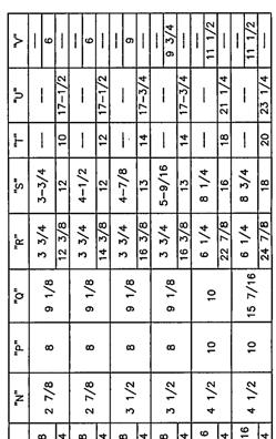
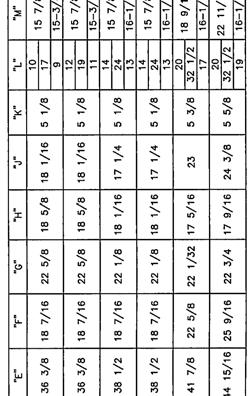
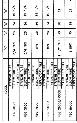
8 Page 8 NFPA MANIFOLD OPTIONS PBG Y6848 (NOT TO SCALE)


9 METRIC NFPA MANIFOLD OPTIONS PBG Page 9 Y6848 METRIC (NOT TO SCALE)
10 Page 10 E. INSTALLATION 1. The Hauck PBG burner can fire in any position. Therefore, they can be installed to fire through side-walls, roofs or the bottoms of ovens, dryers, or furnaces. It may be necessary to rotate the gas ratio regulator so that the stem (adjusting spring) housing is pointing downward. Also, the installation instructions for the UV scanner, control motors and combustion air pressure switches should be reviewed to insure that the mounting arrangement is in accordance with the manufacturer s recommendations. 2. The PBG burners will bolt to the oven or furnace wall. Prepare the oven wall appropriately to support the weight of the burner and any other associated components. Install the burner combustor tube/tile so that it projects past the interior of the oven or furnace wall. Wall thickness should not exceed 6 inches (150mm). For walls thicker than 6 inches (150mm), consult Hauck for recommendations. The optional refractory combustor tile should be installed flush with the interior wall for applications above 1500 F (816 C). 3. For air heating installations where the burner will fire into a chamber under negative pressure, spacers may be installed between the burner mounting bracket and the oven/furnace wall to draw secondary air past the firing tube. 4. On installations where there is a positive pressure within the combustion chamber, the opening in the oven or furnace wall should be at least 1 inch (25mm) larger than the burner combustor tube/tile. Pack the space around the tube with ceramic fiber suitable for the temperatures involved. Ceramic fiber packing should not extend past the 6 inch (150mm) maximum wall thickness. Installation of the high temperature gasket between the burner mounting plate/flange and the oven or furnace wall is recommended for all positive pressure ovens or furnaces. 5. If the burner will be located outdoors, protection should be provided to prevent rain and/or snow from being drawn into the blower. Properly select all accessory items for outdoor operation. A rain hood or other suitable protection is recommended for burners installed in areas of direct rain or snow exposure; contact Hauck for recommendations. 6. If the Hauck PBG burner is to be operated within an enclosed area, verify that an adequate fresh air supply is available to supply combustion air to the burner. F. ELECTRICAL POWER SUPPLY Local and national codes and/or standards should be adhered to. Voltage, phase and frequency must be compatible with the motor and electrical accessory nameplate ratings. All wiring to the burner blower, air control motor, and control accessories must be completed before the burner is ignited. NOTE If the PBG burner will be subjected to backpressure from the chamber or furnace into which it is firing, a large blower motor may be required to achieve the desired heat input; consult Hauck. G. GAS SUPPLY SPECIAL NOTE Hauck recommends the use of gas manifolds conforming to National Fire Protection Association (NFPA) standards. NFPA requires two safety shutoff valves wired in series, equipment isolation valve, sediment trap and strainer upstream of the first shutoff valve, manual shutoff valve downstream of the second (blocking) shutoff valve, and high and low gas pressure switches interlocked to the burner's safety shutoff valves. Additionally, each burner above 150,000 Btu/hr must have visual position indication on each shutoff valve. Burners above 400,000 Btu/hr must have visual position indication in each safety shutoff valve and at least one proof of closure switch. The Hauck PBG with NFPA options contains all of these features.
11 Page 11 The Hauck PBG Burners are designed to operate with a regulated gas supply pressure to the inlet of the manifold of 14 to 21"wc (3.5 to 5.2kPa) for natural gas at a nominal HHV of 1034 Btu/ft 3 (LHV of MJ/Nm 3 ) or propane at a nominal HHV of 2499 Btu/ft 3 (LHV of 91.2 MJ/Nm 3 ). The exact specification of either natural gas or propane should be specified when the burner is ordered. If adequate gas pressure is not available, high fire capacity will be reduced, and low fire ignition may be erratic. For multiple burner installations that use a common prepiped gas manifold, insure that the gas supply pressures to the individual burners are within the 14 to 21"wc (3.5 to 5.2kPa) range. To simplify piping and assure accurate burner control, it is strongly suggested that control of the combustion air and gas be accomplished via the valves/regulators packaged with the burners and not with central or common air and gas valves/regulators. The Hauck PBG Burners have been assembled and adjusted for the gas specified on the purchase order. The burner should require only minimal field adjustment. If it is desired to change the gas specifications, please contact Hauck for recommendations on replacing the fixed high fire gas orifice and adjusting the low fire bypass. H. INITIAL SET-UP WARNING Adjustment of this equipment by unqualified personnel can result in fire, explosion, severe personal injury, or even death. The PBG is factory adjusted to conform to capacity and ignition limits. Although the burner should require no adjustment upon initial set-up, several adjustments can be made in situations where the burner needs to be fine tuned to the application. 1. Combustion Air Valve The combustion air valve travels 90 from closed to the fully open position. A flexible coupling attaches the control motor to the air damper. The air valve must be in the closed position for ignition. 2. PBG 300, 500, 750 & 1000 The above sizes incorporate a low fire air adjustment screw. The screw will affect the low fire appearance of the flame. The screw is factory set to achieve 0.2"wc (50Pa) at the air pressure tap on the burner body. To adjust low fire air, loosen the locknut, then turn the screw. Clockwise rotation will reduce low fire air flow and result in a more luminous flame, while counter clockwise rotation will result in a less luminous flame. Tighten the locknut when the adjustment is complete. 3. Gas Ratio Regulator The gas ratio regulator proportions gas flow through the burner relative to the burner air pressure. Adjusting the bias of the regulator can increase or decrease the ratio of gas to the burner air. The bias adjustment is located under the cap on the regulator stem. Clockwise adjustment of the bias screw will increase gas flow, while counter clockwise adjustment will decrease gas flow. An adjustment of the bias will affect the high and low fire performance of the burner. Be sure to check both high and low fire after adjusting the bias. Be sure the burner will ignite after a bias adjustment. A maximum ¼ turn at each adjustment is recommend, then re-check burner ignition and firing performance. The bias has been factory set for operation at a zero backpressure condition.
12 Page 12 I. IGNITION Each PBG comes equipped with a spark igniter. Since PBG burners are preset, no adjustment to the igniter should be necessary upon initial light-off. However, if ignition problems occur or a new igniter is installed, follow the procedure in Figure 1 to replace and adjust the igniter. Spark ignition requires the burner to be properly grounded to the oven/furnace. X6556 (NOT TO SCALE) Figure 1. Spark Igniter Installation
13 Page 13 J. OPERATION Sequential operation of the PBG burner will depend on the control method used on the burner. Typically, the following will occur. Consult with control system instructions specific to the installation to verify exact operation sequence. 1. Panel is energized, and burner control motor opens to the high fire position. 2. Gas pressure, temperature and auxiliary limits close. 3. High fire limit switch closes. 4. Combustion air blower starts. 5. Combustion air pressure switch closes. 6. Purge timer starts. 7. Purge completes. 8. Burner control motor drives to low fire. 9. Low fire limit switch closes. 10. Ignition sequence starts. a. Ignition transformer is energized. b. Gas safety shutoff valves open. 11. Flame is detected (upon successful light-off). 12. Ten-second trial for ignition completes. 13. Burner control motor responds to temperature controller output. NOTE Maintain electrical power supply to the blower motor until the chamber or furnace temperature is below 200 F (93 C). If the blower is shut off with a hot chamber, hot air may exhaust through the burner and damage internal components. K. FLAME MONITORING The PBG burner may be ordered with either a flame rod or an ultraviolet (UV) scanner. If UV scanners are used on an oven or furnace with multiple burners, care should be exercised so that the UV scanner from one burner does not sense the flame from another burner in the oven or furnace. WARNING If standard full wave coil ignition transformer is used along with the UV flame scanner, provisions must be made to eliminate the possibility of the ignition transformer falsely satisfying the UV scanner. Hauck designed flame supervisory panels eliminate this potential problem by timing out the spark igniter after the trial for ignition period.
14 Page 14 L. SHUT-OFF VALVE LEAK TESTING In addition to leak testing the entire manifold, the automatic shutoff valves should also be leak tested. Both the main and blocking valve should be leak tested on a yearly basis at minimum. Refer to the gas piping diagram for leak testing shown in Figure 2. Figure 2. Gas Piping Diagram for Leak Testing W7610 (NOT TO SCALE) 1. Shutoff the burner(s) and furnace. 2. Close the manual shutoff valve downstream of Safety Shutoff Valve No Open the equipment isolation valve upstream of Safety Shutoff Valve No Bleed off trapped gas by opening both Leak Test Valves No. 1 and No Close Leak Test Valve No Connect 3/16" (4.8mm) ID tubing to Leak Test Valve No. 1 and immerse the open end of the tubing in a container of water. Hold the tubing vertically 1/8 to 1/4" (3 to 6 mm) below the surface. If bubbles appear, record the leakage rate in bubbles/min and refer to the IMPORTANT note at the end of this section. 7. Close Leak Test Valve No. 1 and apply auxiliary power to open Safety Shutoff Valve No Wait several minutes so that any leakage through Safety Shutoff Valve No. 2 will have time to fill the pipe between Safety Shutoff Valve No. 2 and the manual shutoff valve. 9. Connect the tubing to Leak Test Valve No. 2 and immerse the open end in water as before. Open Test Valve No. 2. If bubbles appear, record the leakage rate in bubbles/min and refer to the IMPORTANT note at the end of this section. 10. When no leaks are detected, open the shutoff valve at the outlet of the PGM and return to normal operation. IMPORTANT The fact that bubbles are present during the leak test does not necessarily mean that a safety shutoff valve is not functioning properly in the closed position. Refer to the National Fire Protection Association s publication NFPA 86 for acceptable leakage rates for a given pipe size per UL, ANSI, CSA, FM or EN standards. If the acceptable bubbles/min leakage rate is exceeded, the safety shutoff valve is leaking and the manufacturer s instructions should be referenced for corrective action. WARNING Do not attempt to operate the combustion system until all leaks are repaired.
15 Page 15 M. MAINTENANCE The Hauck PBG Packaged Burner has no moving parts requiring lubrication. However, preventative maintenance can eliminate costly down time. Periodic maintenance should include the following: 1. Check all pressure switches, clean or replace if necessary. For recommended pressure settings see table below. Switch Low Air Pressure High Gas Pressure Low Gas Pressure Pressure Settings 4"wc (1.0 kpa) 1 psi (6.9 kpa) 13"wc (3.2 kpa) 2. Check bolts and screws for tightness. 3. Check operation of flame safety equipment. 4. On a yearly basis as a minimum, the safety shutoff valve manifold should be leak tested and any leaks be repaired immediately (see Section L). 5. The PBG uses a self-cleaning fan blade which eliminates the build-up of most deposits. If an optional air filter is supplied, periodic cleaning is required to keep the burner operating at maximum efficiency. a. Remove blower assembly from burner body. Be sure to remove any control components and wiring. b. Remove inlet housing cover. c. Using a thin, plastic bristle brush, gently remove any buildup from the fan blades. d. Carefully blow out the fan housing with compressed air to remove any loosened debris. e. Attach the blower to the burner body and reconnect all components. 6. Should it become necessary to remove the spark igniter for cleaning or inspection, the spark igniter must be inserted with the proper orientation to ensure ignition (see Figure 1). The flame rod, if used, inserts the same way as the spark igniter (see Figure 1), however, no particular orientation is required. NOTE The PBG spark igniter and flame rod are NOT interchangeable. However, if required for clearance or convenience, the spark igniter and flame rod or UV scanner can be installed in either port. N. RECOMMENDED SPARE PARTS ITEM DESCRIPTION QTY. PART NO. 1 Spark Igniter Assembly (If Applicable) 1 See Parts List 2 Flame Rod Assembly 1 See Parts List 3 UV Scanner (If Applicable)
16 Page 16 This page left intentionally blank. HAUCK MANUFACTURING CO., P.O. Box 90 Lebanon, PA Fax:
NMG NOZZLE MIX GAS BURNERS
 INSTRUCTIONS NMG NOZZLE MIX GAS BURNERS WARNING These instructions are intended for use only by experienced, qualified combustion start-up personnel. Adjustment of this equipment and its components, by
NOZZLE MIX COMBINATION BURNER NMC200 SERIES
 NOZZLE MIX COMBINATION BURNER NMC200 SERIES INSTRUCTIONS WARNING These instructions are intended for use only by experienced, qualified combustion start-up personnel. Adjustment of this equipment and its
LHE OIL LINE HEATER ELECTRIC TYPE
 INSTRUCTIONS LHE OIL LINE HEATER ELECTRIC TYPE WARNING These instructions are intended for use only by experienced, qualified combustion start-up personnel. Adjustment of this equipment and its components
HAUCK STARJET BURNER SJ075 SJ980
 INSTRUCTIONS HAUCK STARJET BURNER SJ075 SJ980 WARNING These instructions are intended for use only by experienced, qualified combustion start-up personnel. Adjustment of this equipment by unqualified personnel
Ecomax. Direct-Fired Self-Recuperative Metallic Gas Burner. Features
 Ecomax Direct-Fired Self-Recuperative Metallic Gas Burner Features Self-recuperative design Heat resistant silicon carbide combustor and cast alloy recuperator Various recuperator lengths available Insulated
STARJET BURNER SJ075 SJ980
 CAPACITIES STARJET BURNER SJ075 SJ980 Burner Model Air Flow (scfm) Pressure (osig) 36 osig 60 Hz Direct Drive Blowers TBA Blower Motor Model HP Fan Rating (acfm @ 350 F) Max. Capacity (MMBtu/hr) SJ075
Eclipse RatioMatic Burners
 Design Guide 110 11/11/2011 Eclipse RatioMatic Burners RM Series Version 5 Copyright Copyright 2010 by Eclipse, Inc. All rights reserved worldwide. This publication is protected by federal regulation and
Specifications of V-Line burners
 Duct Burners - V-Line 4-22.5-7 Specifications of V-Line burners V-Line burner firing on natural gas - constant combustion air 60 F - 21% O 2 combustion air - 50% rel. humidity - natural gas with 1000 Btu/ft³
Eclipse AirHeat Burner
 135 Design Guide 6/16/2010 Eclipse AirHeat Burner AH Serie Version 2 Copyright Copyright 1999 by Eclipse, Inc. All rights reserved worldwide. This publication is protected by federal regulation and shall
Design Guide 111 9/25/2008. Eclipse Winnox Burners WX Series Version 1
 Design Guide 111 9/25/2008 Eclipse Winnox Burners WX Series Version 1 Co p y r i g h t Disclaimer Notice Copyright 2005 by Eclipse, Inc. All rights reserved worldwide. This publication is protected by
INDITHERM. Low temperature gas burners
 INDITHERM Low temperature gas burners 1-2.3-1 High turndown for maximum operation flexibility. Maximum capacities up to 1800 kw. Designed for firing in indirect fired processes. Excellent combustion throughout
NMC Nozzle Mix Gas/Oil Combination Burners
 NMC Nozzle Mix Gas/Oil Combination Burners NMC-1 Edition 10-08 Burns most gaseous fuels and No. 2 oil Sealed-in capability Stable flame over entire operating range Preheated air to 800ºF (425ºC) Gas pilot
MEGASTAR TM BURNER MS-25 MS-150
 INSTRUCTIONS MEGASTAR TM BURNER MS-25 MS-150 WARNING These instructions are intended for use only by experienced, qualified combustion startup personnel. Adjustment of this equipment by unqualified personnel
Design Guide No /01. RatioMatic Burners. RM Series Version 3.10
 Design Guide No.110 12/01 RatioMatic Burners RM Series Version 3.10 COPYRIGHT Copyright I998 by Eclipse Combustion, Inc. All rights reserved worldwide. This publication is protected by federal regulation
OPERATING AND MAINTENANCE MANUAL
 OPERATING AND MAINTENANCE MANUAL NVPOM-0104 TABLE OF CONTENTS Section Page 1 SPECIFICATIONS...1 1.1 Nova Plus Specifications...1-1 1.2 Warranty...1-2 2 GENERAL BURNER DESCRIPTION...2 2.1 Burner...2-1 2.2
ECLIPSE INFORMATION GUIDE
 ECLIPSE INFORMATION GUIDE JUNIOR INDUSTRIAL BURNERS Models 0 & 6 JIB Info 80 0/9 Easy to install and operate. Rugged construction for long life in industrial environments. Protection against overheating
Installation Instructions
 Model 500-SP OVENPAK Burners Page 2300-S-1 Installation Instructions General Instructions Important: Do not discard packing material until all loose items are accounted for. To prevent damage in transit,
Internet Version for Reference Only INDUCED DRAFT COMMERCIAL WATER HEATERS SUPPLEMENT INSTRUCTIONS TO PART #
 INDUCED DRAFT COMMERCIAL WATER HEATERS SUPPLEMENT INSTRUCTIONS TO PART #238-39387-00 THIS INSTRUCTION SUPPLEMENT IS ONLY INTENDED TO GIVE INSTALLATION INSTRUCTIONS AND INFORMATION RELATED TO THE INDUCED
ECLIPSE INFORMATION GUIDE
 ECLIPSE INFORMATION GUIDE EXTENSO-JET SMALL BORE BURNERS Info 230 8/91 CONTENTS PAGE CONTENTS PAGE Safe Burner Operation... 2 1.0 Applications... 2 2.0 Burner Operating Parameters & Requirements 2.1 Capacities
Design Guide /12/2008. Eclipse RatioAir Burners RA Series Version 1
 Design Guide 115 11/12/2008 Eclipse RatioAir Burners RA Series Version 1 Co p y r i g h t Disclaimer Notice Copyright 2005 by Eclipse, Inc. All rights reserved worldwide. This publication is protected
Eclipse AirHeat Burners
 Design Guide No. 135, 7/99 L00060 Eclipse AirHeat Burners AH Series Version 2.00 (Patent Pending) Eclipse Combustion COPYRIGHT Copyright I999 by Eclipse Combustion, Inc. All rights reserved worldwide.
T-CLASS GAS-FIRED UNIT HEATERS Separated Combustion - Direct Vent - Horizontal - 60 HZ. Thermal Efficiency - up to 82% Input - 40,000 to 300,000 Btuh
 PRODUCT SPECIFICATIONS GAS UNIT HEATERS / DUCT FURNACES TU T-CLASS GAS-FIRED UNIT HEATERS Separated Combustion - Direct Vent - Horizontal - 60 HZ Bulletin No. 20402 November 207 Supersedes November 206
Columbia Boiler Company
 EMG Series Boilers Available in Natural Gas & Propane Rev 12012 Columbia Boiler Company PO Box 1070 Pottstown, PA 19464 Tel (610) 473-8457 Fax (610) 367-6800 Website www.columbiaboiler.com Email cbcsales@ptd.net
Gas Fired Humidifier. SKG Series Combustion Field Adjustment Instructions. SKG Combustion Field Adjustment Instructions
 Fired Humidifier SKG Series SKG - 180301 Standard Combustion Adjustment SKG Fired Humidifier All installation work must be carried out by suitably qualified personnel and must conform to local codes and
Line Pressure ( w.c.) Gas Supply Min. Max. Pressure ( w.c.) Natural Gas Propane Gas
 Gas Supply Min. Max. Pressure ( w.c.) Natural Gas Propane Gas") HVAC Guideline Specifications WHISPER-JET: SET SERIES Two Stage Positive Pressure Gas-Fired Infrared Radiant Tube Type Heater Commercial/Industrial Applications Technical Summary Input Range: 80,000/60,000
HVAC Guideline Specifications WHISPER-JET: SET SERIES Two Stage Positive Pressure Gas-Fired Infrared Radiant Tube Type Heater Commercial/Industrial Applications Technical Summary Input Range: 80,000/60,000
Direct Fired Heater Model AD Specification
 Direct Fired Heater Model AD Specification Description A Direct-fired gas heating and ventilating unit(s), as indicated on the drawings shall be furnished. Unit(s) shall be tested in accordance with ANSI
INSTALLATION GUIDE Dual Fuel Ranges
 INSTALLATION GUIDE Dual Fuel Ranges Contents Wolf Dual Fuel Ranges......................... 3 Safety Instructions............................ 4 Dual Fuel Range Specifications.................. 5 Dual Fuel
Internal ridged board 1" x 1.5 foil face installation shall be installed on roof, walls and base of casing.
 A-D WITH MPU SPECIFICATION WRITTEN SPECIFICATION Description A Modular Packaged Heating, Cooling and ventilating unit(s), as indicated on the drawings shall be furnished. Direct Fired Gas Unit(s) shall
DESCRIPTION, CAPACITIES, SPECIFICATIONS, APPLICATIONS
 INTEGRAL FAN BURNERS 43, 53, 63 Supplement 600- July 996 DESCRIPTION, CAPACITIES, SPECIFICATIONS, APPLICATIONS Integral Fan (and) Shutter Section (hinged for quick access to internals) Combustion Air Interlock
SERVICE AND INSTALLATION MANUAL MODELS HDO(H) OIL FOR YOUR SAFETY
 OIL FOR YOUR SAFETY") Bousquet Technologies Inc. 2121, Nobel, Ste Julie, Quebec, Canada, J3E1Z9 SERVICE AND INSTALLATION MANUAL MODELS HDO(H) OIL Oil-Fired air heater for industrial and commercial use. FOR YOUR SAFETY Do not
Bousquet Technologies Inc. 2121, Nobel, Ste Julie, Quebec, Canada, J3E1Z9 SERVICE AND INSTALLATION MANUAL MODELS HDO(H) OIL Oil-Fired air heater for industrial and commercial use. FOR YOUR SAFETY Do not
SERVICE FACTS WARNING M801-SF-1C. Gas Furnaces Upflow & Downflow Induced Draft 1 Stage Heat Models: DISCONNECT POWER BEFORE SERVICING M801P040AU24AA
 SERVICE FACTS Gas Furnaces Upflow & Downflow Induced Draft Stage Heat Models: M80P00AU2AA M80P060AU2AA M80P060AU36AA M80P080BU36AA M80P080BU8AA M80P00BU36AA M80P00CU8AA M80P00CU60AA M80PDU60AA M80P0DU60AA
SAMPLE SPECIFICATION FOR RIELLO ARRAY MODULATING BOILER
 SAMPLE SPECIFICATION FOR RIELLO ARRAY MODULATING BOILER PART 1 GENERAL 1.01 RELATED DOCUMENTS A. ANSI Z21.13 American National Standard for Gas-Fired Low Pressure Steam and Hot Water Boilers B. ASME Section
A. Product Data: Include rated capacities, furnished specialties and accessories.
 BASE BID: SECTION 15542 FUEL-FIRED RADIANT HEATERS PART 1 - GENERAL 1.1 SUMMARY A. Furnish and install a Co-Ray-Vac Low Intensity Vented Infrared Radiant Vacuum Gas Heating System. System must be certified
INDITHERM. Low temperature gas burners
 INDITHERM Low temperature gas burners 1-2.3-1 High turndown for maximum operation flexibility. Maximum capacities up to 1800 kw. Designed for firing in indirect fired processes. Excellent combustion throughout
S150 S300 CONSTRUCTION HEATERS. Rev: August 15, 2008 SERVICE AND MAINTENANCE MANUAL No PLEASE RETAIN FOR FUTURE REFERENCE PRODUCTS
 S150 & S300 CONSTRUCTION HEATERS Rev: 2.7.2 August 15, 2008 SERVICE AND MAINTENANCE MANUAL No. 934-6637 PLEASE RETAIN FOR FUTURE REFERENCE PRODUCTS A DIVISION OF HAUL-ALL EQUIPMENT LTD. 4115-18 Avenue
Eclipse ImmersoJet Burner
 Design Guide 330 11/15/2016 Eclipse ImmersoJet Burner IJ Series Version 3 Copyright Copyright 2005 by Eclipse, Inc. All rights reserved worldwide. This publication is protected by federal regulation and
Power Flame Incorporated
 Power Flame Incorporated SUGGESTED SPECIFICATION FOR MODEL NVC ULTRA LOW NOx GAS BURNERS SUB 9 PPM NOx THE POWER TO MANAGE ENERGY 2001 South 21st Street, Parsons, Kansas 67357 Telephone: 620-421-0480,
Indirect gas-fired air heater
 Indirect gas-fired air heater SERIES HD INSTALLATION AND SERVICE MANUAL MANUFACTURED BY : BROTHERS LIMITED WARNING Improper installation, modification, adjustment or maintenance may cause damage, injury
Specifications of MULTIFIRE burners
 -.-6 High temperature burners - MULTIFIRE Specifications of MULTIFIRE burners Gas firing Typical burner data Fuel: natural gas at 60 F with 000 tu/ft³ (st) HHV - sg = 0.6 [] Combustion air: 60 F - % O
Design Guide No. 330, 10/02 Immersion Burners
 Design Guide No. 330, 10/02 Immersion Burners ImmersoJet Series version 2.20 COPYRIGHT Copyright I997 by Eclipse Combustion, Inc. All rights reserved worldwide. This publication is protected by federal
GAS FURNACES G20RE/ G20RXE EXISTING NEG ENGINEERING DATA EXISTING NEG. Typical Applications
 ENGINEERING DATA Typical Applications G20RE and G20RXE WhisperHeat DOWN-FLO GAS FURNACES *78.0% A.F.U.E. 50,000 to 150,000 Btuh Input Add-On Cooling 2 thru 5 Nominal Tons *Isolated Combustion System rating
Installation & Service Instructions for Jackson & Church Flexaire Packaged Furnaces SDF-125 thru SDF-400 Gas Firing
 Installation & Service Instructions for Jackson & Church Flexaire Packaged Furnaces SDF-125 thru SDF-400 Gas Firing Important: To protect the unit and avoid damage to the heat exchanger, the blower speed
POWER VENTER. Model: PVE Series
 POWER VENTER Model: PVE Series CONTENTS Typical Venting System Components... System Operation... Power Venter Sizing... Installation Safety Instructions... Installation of Power Venter... Connecting Power
QHT Manual for: SU-2A Gas Burner
 1 QHT Manual for: SU-2A Gas Burner 50,000 BTU/H to 250,000 BTU/H The burner shall be used only with NATURAL GAS or LP GAS. Warning: If the following instructions are not followed exactly, a fire or explosion
CROWN. Boiler Co. Santa-Fe Series. Hydronic Air Handlers INSTALLATION, OPERATION & MAINTENANCE INSTRUCTIONS
 CROWN Boiler Co Santa-Fe Series Hydronic Air Handlers INSTALLATION, OPERATION & MAINTENANCE INSTRUCTIONS These instructions must be affixed on or adjacent to the air handler Models: SAC049A20 SAC059A25
GUIDE SPECIFICATION ADVANCED RADIANT SYSTEMS DU/DUH DUAL OUTPUT RANGE INFRARED TUBE HEATERS
 GUIDE SPECIFICATION ADVANCED RADIANT SYSTEMS DU/DUH DUAL OUTPUT RANGE INFRARED TUBE HEATERS SECTION 15540 FUEL- FIRED HEATERS (Alternate - SECTION 235523 - GAS-FIRED RADIANT HEATERS) This section is based
STR-Series Indirect-Fired Air Turnover Units
 STR-Series Indirect-Fired Air Turnover Units Equipment Specifi cations 1.800.589.3691 www.weather-rite.com GAS/OIL HEATING ONLY INDIRECT-FIRED AIR TURNOVER UNIT GUIDE SPECIFICATIONS PART 1 GENERAL [Gas][Oil][Gas/Oil
KGA092 SHOWN READ ALL INSTRUCTIONS IN THIS MANUAL AND RETAIN FOR FUTURE REFERENCE WARNING
 See unit nameplate for manufacturer and address. 506380 01 11/2009 KGA024, 030, 036, 048, 060, 072 (2, 2 1/2, 3, 4, 5, and 6 Tons) KGA092, 102, 120, 150 (7 1/2, 8-1/2, 10, and 12 Tons) KGA180, 210, 240,
Installation, Operation and Maintenance Manual
 Part #461006 Indirect Gas-Fired Furnaces Installation, Operation and Maintenance Manual Please read and save these instructions. Read carefully before attempting to assemble, install, operate or maintain
CYLINDER NOT INCLUDED
 OPERATING INSTRUCTIONS AND OWNER S MANUAL Model # HS125NG / MH125LP / HS125LP READ INSTRUCTIONS CAREFULLY: Read and follow all instructions. Place instructions in a safe place for future reference. Do
Gas-Fired Indoor and Outdoor Duct Furnaces
 July, 2008 Gas-Fired Indoor and Outdoor Duct Furnaces INDOOR GRAVITY VENTED DFG, DBG, DCG INDOOR SEPARATED COMBUSTION DFS, DBS, DCS OUTDOOR GRAVITY AND POWER EXHAUSTED H Series table of contents A complete
Design and Application Details
 Series 67 TUBE-O-FLAME Gas Burners Page 2203 Design and Application Details Maxon TUBE-O-FLAME Burners are nozzlemixing, gas-fired, refractory-less burners specifically designed for firing into an immersion
Cambridge Engineering, Inc. 24 S-Series Technical Manual
 Start-Up Instructions START-UP PROCEDURE 1. Visual Inspection Of Equipment (page 24) 2. Electrical Supply Voltage Verification (page 24) 3. Gas Supply Pressure Verification (page 24) 4. Blower Rotation
FEATURES AND BENEFITS
 FEATURES AND BENEFITS Product Features and Benefits Full Product Line Offering Feature All models are 80% thermally efficient Blower performance up to 3.0 W.C. DX or chilled water section with factory
National Comfort Products 539 Dunksferry Road Bensalem, PA (215) Fax: (215)
 Fax: (215)") National Comfort Products 539 Dunksferry Road Bensalem, PA 19020 (215) 244-1400 1-800-523-7138 Fax: (215) 639-1674 14299575-10/29/2014 NOTE: These installation and maintenance instructions should be left
National Comfort Products 539 Dunksferry Road Bensalem, PA 19020 (215) 244-1400 1-800-523-7138 Fax: (215) 639-1674 14299575-10/29/2014 NOTE: These installation and maintenance instructions should be left
Type CG Series Forced Draft Gas Burner
 Type CG Series Forced Draft Gas Burner Designed and built by Canadians for Canadian Winters By PENDELL BURNERS Office & Plant Address: 155 Regina Road, Unit #3 Woodbridge, Ontario L4L 8L9 Telephone: (416)
A AD Oil burners fuel unit. deltapumps.com. DE A-AD_en_0709.pdf Page 1/1
 A AD Oil burners fuel unit deltapumps.com DE116-0709 A-AD_en_0709.pdf - 16.11.09 Page 1/1 Oil burners fuel unit Type A, AD 1- Applications The DELTA aluminium fuel unit type A is an efficient and modern
POWER VENTER SYSTEM. Model: PVO-300, PVO-600
 POWER VENTER SYSTEM Model: PVO-300, PVO-600 Included is one ETL and cetl listed Power Venter to be used primarily with a single 120VAC controlled oil fired furnace, boiler, or water heater. The PVO may
Revitalize Building Mechanical Systems (4619)
") SECTION 235216 FIRE-TUBE CONDENSING BOILERS PART 1 - GENERAL 1.1 RELATED DOCUMENTS A. Drawings and general provisions of the Contract, including General and Supplementary Conditions and Division 01 Specification
SECTION 235216 FIRE-TUBE CONDENSING BOILERS PART 1 - GENERAL 1.1 RELATED DOCUMENTS A. Drawings and general provisions of the Contract, including General and Supplementary Conditions and Division 01 Specification
Fire Bowls and Fire Bowl Inserts (Automated Operation) Operating and Maintenance Instructions
 Operating and Maintenance Instructions") Table of Contents Section 1: Gas and Electric Requirements... 1 Section 2: Installation... 2 Section 3: Burner Setup and Adjustment... 8 Burner Adjustment... 9 Section 4: Maintenance... 10 Section 5: Operation...
Table of Contents Section 1: Gas and Electric Requirements... 1 Section 2: Installation... 2 Section 3: Burner Setup and Adjustment... 8 Burner Adjustment... 9 Section 4: Maintenance... 10 Section 5: Operation...
INSTALLATION, OPERATING & MAINTENANCE INSTRUCTIONS FOR 350 SERIES CIRCULATION HEATERS
 INDEECO Circulation Heaters are designed to provide years of trouble free operation if properly installed and maintained. Please read and follow these instructions for installing and maintaining the heater.
APX. Nozzle-mix line burner
 APX Nozzle-mix line burner Duct burners - APX Burner 4-21.9-1 Nozzle-mixing line burner for use with low pressure natural gas, propane and butane Eliminates leakage with its single-piece, aluminium extrusion
RSIF power venter USA CAN READ AND SAVE THESE INSTRUCTIONS! Installation and operation manual. Product information Chapters 1 + 2
 3002239 RSIF 2014-04-04 Installation and operation manual RSIF power venter READ AND SAVE THESE INSTRUCTIONS! Product information Chapters 1 + 2 Mechanical installation Chapter 3 Electrical installation
RSIF Power Venter USA CAN. Product Information. ... Chapters Mechanical Installation. ... Chapter 3. Electrical Installation. ...
 Installation & Operating Manual RSIF Power Venter USA CAN Product Information... Chapters 1 + 2 Mechanical Installation... Chapter 3 Electrical Installation... Chapter 4 Start Up and Configuration... Chapter
Product Information. Model: HG, HL, HLG Burner Sizes: 10, 13, 15, 17, 20, 21, 25 GENERAL DESCRIPTION U.L. STANDARD EQUIPMENT
 The H/Series gas, oil, and combination gas/oil burner is a forced draft packaged burner system. A backward curved impeller mounted in a machined housing provides combustion air for various furnace pressures
8+* Bulletin No November 1997
 ENGINEERING DATA VALUE 80Z UP-FLOW/HORIZONTAL GAS FURNACES *80.0 to 80.5% A.F.U.E. 45,000 to 20,000 Btuh (3.2 to 32.2 kw) Input Heating Capacity -/2 thru 6 Tons (3.5 thru 2. kw) Nominal Add-on Cooling
BURNERS/ FLARES. VAREC BIOGAS 244W Series WASTE GAS BURNER & IGNITION SYSTEM
 BURNERS/ FLARES VAREC BIOGAS 4W Series WASTE GAS BURNER & IGNITION SYSTEM The Varec Biogas 4W Series Waste Gas Burner is a highly reliable flare and ignition system ideal for use in burning excess biogas.
Niles Steel Tank Hot Water Generator Installation and Operation Manual
 Niles Steel Tank Hot Water Generator Installation and Operation Manual Contents: Contents 1 Hazard definitions 1 1. General Information.... 2 Availability... 3 Optional Control Packages... 5 2. Installation....
Project Name: Location: Engineer: Contractor: I. GENERAL
 Part I - General Part II - Product Part III - Installation Project Name: Location: Engineer: Contractor: I. GENERAL I. PRODUCT Rep: Date: A. Supply and install modulating and condensing boiler(s) as specified
ZG Shown READ ALL INSTRUCTIONS IN THIS MANUAL AND RETAIN FOR FUTURE REFERENCE WARNING
 See unit nameplate for manufacturer and address. 507258-04 7/2018 Supersedes 10/2017 ZG 036, 048, 060, 072, 074 (3, 4, 5 and 6 Tons) ZG 092, 102, 120, 150 (7-1/2, 8-1/2, 10 and 12 Tons) ROOFTOP UNITS ZG
USER S, MAINTENANCE and SERVICE INFORMATION MANUAL
 CONTENTS SAFETY INFORMATION................ 2 FOR YOUR SAFETY...................... 2 SYSTEM OPERATION.................. 2 THERMOSTATS.......................... 2 INTERMITTENT IGNITION DEVICE..........
Hubbell NX500 High Efficiency Gas Condensing Water Heater
 Hubbell NX500 High Efficiency Gas Condensing Water Heater Suggested Specification Part I - General Part II - Product Part III - Installation Project Name: Location: Engineer: Contractor: I. GENERAL Rep:
USER S, MAINTENANCE and SERVICE INFORMATION MANUAL
 CONTENTS SAFETY INFORMATION................ 2 FOR YOUR SAFETY....................... 2 SYSTEM OPERATION.................. 2 THERMOSTATS.......................... 2 INTERMITTENT IGNITION DEVICE...........
JADE TACO RANGES MODEL: JTR and JTRB Series JADE STOCK POT RANGES MODEL: JSP Series
 Jade Range LLC, A Middleby Company 2650 Orbiter Ave. Brea, CA 92821 Telephone (714) 961-2400 FAX (714) 961-2550 JADE TACO RANGES MODEL: JTR and JTRB Series JADE STOCK POT RANGES MODEL: JSP Series INSTALLATION,
CSD-1 COMMERCIAL BOILER CONTROLS
 SUPPLEMENTAL INSTALLATION AND OPERATING INSTRUCTIONS CSD- COMMERCIAL BOILER CONTROLS P/N 400043, Rev. A [/03] CSD- COMMERCIAL BOILER CONTROLS! WARNING Fire, explosion, asphyxiation and electrical shock
UV Scanner. Model Specification. Introduction. 854 Instruction Manual
 854 Instruction Manual 10/11/010 UV Model 5600-91 C US Introduction This sensor features a high temperature and high sensitivity ultraviolet (UV) tube for monitoring gas or oil flames in applications that
COMPACT UNIT HEATERS Low Profile - Horizontal - 60 HZ. Steady-State Efficiency - up to 81% Input - 30,000 to 75,000 Btuh
 GAS UNIT HEATERS / DUCT FURNACES LF24 COMPACT UNIT HEATERS Low Profile - Horizontal - 60 HZ PRODUCT SPECIFICATIONS Bulletin 2008 July 206 Supersedes October 20 Steady-State Efficiency - up to 8% Input
"NP" & "RG" AIRFLO. In-duct firing line burner
 "NP" & "RG" AIRFLO In-duct firing line burner Duct burners - NP & RG AIRFLO 4-21.5-1 For direct fired fresh air heating applications Operates economically (100 % thermal efficiency) and installs easily
Manual installation AW-D. Direct Gas Fired Make-Up Air Series. Revision: v001 Issue Date: 12/12/ Price Industries Limited. All rights reserved.
 Manual installation AW-D Direct Gas Fired Make-Up Air Series Revision: v001 Issue Date: 12/12/14 2014 Price Industries Limited. All rights reserved. Table of contents Overview General Safety Information...1
SECTION DIRECT GAS-FIRED INDUSTRIAL HEATING AND VENTILATING UNITS
 SECTION 237339 - DIRECT GAS-FIRED INDUSTRIAL HEATING AND VENTILATING UNITS PART 1 - GENERAL 1.1 RELATED DOCUMENTS A. Drawings and general provisions of the Contract, including General and Supplementary
LATTNER BOILER COMPANY 9.5 HP Low-NOx Installation and Start-Up Checklist for Dry Cleaners
 1 1. General Installation Information (to be completed by technician) Date installed: Location (city & state): Cleaner s name: National Board number (boiler): Installed by (company): Installed by (technician):
ClearFire. Startup Guide. Model CFH. Horizontal Steam Boiler
 ClearFire Model CFH Horizontal Steam Boiler Startup Guide 750-293 www.cleaverbrooks.com Improper installation, adjustment, service, or maintenance can cause equipment damage, personal injury, or death.
GUIDE SPECIFICATION ADVANCED RADIANT SYSTEMS SL/SLV SIRIUS LINEAR RANGE HIGH EFFICIENCY CONTINUOUS INFRARED SYSTEMS
 GUIDE SPECIFICATION ADVANCED RADIANT SYSTEMS SL/SLV SIRIUS LINEAR RANGE HIGH EFFICIENCY CONTINUOUS INFRARED SYSTEMS SECTION 15540 FUEL- FIRED HEATERS (Alternate - SECTION 235523 - GAS-FIRED RADIANT HEATERS)
PVE SERIES POWER VENTER SYSTEM MANUAL
 PVE SERIES POWER VENTER SYSTEM MANUAL Contents Page I. Typical Venting System Components 2 II. System Operation 3 III. Power Venter Sizing 3,4 IV. Installation Safety Instructions 5,6 V. Installation of
TGA/KGA024, 030, 036, 048, 060, 072, 090 (2, 2 1/2, 3, 4, 5, 6, and 7 1/2 TONS)
") See unit nameplate for manufacturer and address. 506003 01 5/2009 Supersedes 1/2008 TGA/KGA024, 030, 036, 048, 060, 072, 090 (2, 2 1/2, 3, 4, 5, 6, and 7 1/2 TONS) TGA090, 102, 120, 150, TGA120 SHOWN (7
See unit nameplate for manufacturer and address. 506003 01 5/2009 Supersedes 1/2008 TGA/KGA024, 030, 036, 048, 060, 072, 090 (2, 2 1/2, 3, 4, 5, 6, and 7 1/2 TONS) TGA090, 102, 120, 150, TGA120 SHOWN (7
G60UH(X) WARNING. WARNING Sharp edges. Be careful when servicing unit to avoid sharp edges which may result in personal injury. Service Literature
 WARNING. WARNING Sharp edges. Be careful when servicing unit to avoid sharp edges which may result in personal injury. Service Literature") Service Literature Corp. 0204 L2 Revised 11 2006 G60UH(X) G60UH(X) SERIES UNITS G60UH(X) series units are mid efficiency gas furnaces used for upflow or horizontal applications only, manufactured with
Service Literature Corp. 0204 L2 Revised 11 2006 G60UH(X) G60UH(X) SERIES UNITS G60UH(X) series units are mid efficiency gas furnaces used for upflow or horizontal applications only, manufactured with
Engineering Bulletin. Gas Heat. for M-Series and T-Series Climate Changer Air Handlers CLCH-PRB010-EN. March 2004
 Engineering Bulletin Gas Heat for M-Series and T-Series Climate Changer Air Handlers March 2004 CLCH-PRB010-EN Preface Gas heat can be a good heating option for any of the following applications: Climates
NFPA 86 Commitee Inputs Page 1 of 45
 of 44 1/26/2017 2:28 PM Committee Input No. 102-NFPA 86-2016 [ Global Input ] The Committee is considering language for pre-purge of the work chambers for Class A, Class B and Class C furnaces. This could
MODEL HS115-3, HS115-4 & HS115-5 WIRING DIAGRAM ADDENDUM
 TJERNLUND PRODUCTS, INC. 1601 Ninth Street White Bear Lake, MN 55110-6794 PHONE (800) 255-4208 (651) 426-2993 FAX (651) 426-9547 Visit our web site www.tjernlund.com MODEL HS115-3, HS115-4 & HS115-5 WIRING
Oil burners fuel unit with solenoid valve
 Oil burners fuel unit with solenoid valve Type VM www.deltapumps.com VM1 - VM4U flanged Certified Quality System Printed in Italy - DE112/0404 Oil burners fuel unit with solenoid valve Type VM The DELTA
INFRARED RADIANT HEATERS
 IRH-1R INFRARED RADIANT HEATERS High and Low Intensity RSU SERIES Unit is shown rotated at a 45 angle. RSD SERIES HIGH INTENSITY INFRARED HEATERS RSD Series Ceramic Heaters Special Honeycomb Tile Design
INDUSTRIAL MICRODIFFUSION OIL BURNERS
 Operations and Maintenance Manual for INDUSTRIAL MICRODIFFUSION OIL BURNERS Models MD-25-O MD-2500-O December 2012 Copyright 2012 Periflame, Design Guide 112 Industrial Oil Burners, 12/01/2012 Page 1 Table
MERIT SERIES Downflow
 PRODUCT SPECIFICATIONS GAS FURNACES ML80DF MERIT SERIES Downflow Bulletin No. 20643 February 208 Supersedes November 207 AFUE - 80% Input - 44,000 to 0,000 Btuh Nominal Add-on Cooling -.5 to 5 Tons MODEL
GP COMBUSTION EQUIPMENT INC 100 Sheldon Dr., Units 16/17 Cambridge, Ontario N1R 7S7. Model C Forced Draft Burners. Natural Gas or Propane MODEL C10
 Model C Forced Draft Burners Natural Gas or Propane MODEL C10 MODEL C4 GP COMBUSTION EQUIPMENT INC 100 Sheldon Dr., Units 16/17 Cambridge, Ontario N1R 7S7 Telephone: (519) 620-0230 Telefax: (519) 620-0232
The key element for your process
 The key element for your process Safety Controls and Burner Management Systems (BMS) Paul Chau, P. Eng. Vice-President (Born Heaters Canada Ltd.) www.adico.co info@adico.co Table Of Contents 1. Introduction...
CONVERSION TO PROPANE MANUAL M-Series Condensing Boiler. Wall-Mounted, Gas-Fired Boiler
 rinnai.us 1-800-621-9419 CONVERSION TO PROPANE MANUAL M-Series Condensing Boiler Wall-Mounted, Gas-Fired Boiler For the Conversion from Natural Gas (NG) to Liquid Propane Gas (LPG) MODELS M060C M090C M120C
KG 092 SHOWN READ ALL INSTRUCTIONS IN THIS MANUAL AND RETAIN FOR FUTURE REFERENCE WARNING
 See unit nameplate for manufacturer and address. 507350-03 3/2016 Supersedes 9/2015 KG 024, 030, 036, 048, 060, 072, 074, 090 (2, 2-1/2, 3, 4, 5, 6 and 7-1/2 Tons) KG 092, 102, 120, 150 (7-1/2, 8 1/2,
Indirect Gas-Fired Make-Up Air
 Indirect Gas-Fired Make-Up Air Model IG 800 to 7,000 cfm Up to 400,000 Btu/hr Multiple Furnace Control Options Optional Evaporative Cooling May 20041 Product Features Model IG Indirect Gas-Fired Make-Up
MULTIPLEX SELF RECUPERATIVE gas burner
 Installation - Maintenance MULTIPLEX SELF RECUPERATIVE gas burner SERIES MPSR The Nu-way Multiplex Recuperative System offers the alternative of a self-recuperative burner or a separate recuperator and
MODEL PVF INDIRECT GAS FIRED FURNACES FOR ENERGY RECOVERY UNITS Installation, Operation, and Maintenance Manual
 RETIN THESE INSTRUCTIONS FOR FUTURE REFERENCE Part # 461006 MODEL PVF INDIRECT GS FIRED FURNCES FOR ENERGY RECOVERY UNITS Installation, Operation, and Maintenance Manual Model PVF, Indirect Gas Furnace,