INSTALLATION INSTRUCTIONS
|
|
|
- Noel Lynch
- 6 years ago
- Views:
Transcription

1 INSTALLATION INSTRUCTIONS FOR AQUECOIL HYDRONIC HEATING UNITS
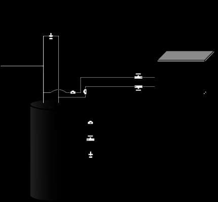
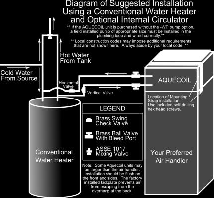
2 GENERAL INFORMATION The AQUECOIL Hydronic Heating Unit is offered in many different capacities and physical configurations in order to match up to the installation and load requirements of a broad number of air distribution systems. Check the Model Number to determine if it is the appropriate unit for the Air Handler already selected or installed at the job site. The AQUECOIL Hydronic Heating Unit consists of a high performance fin tube water-to-air heat exchanger, an optional water-cooled circulating pump and an optional valve package. Pump power is derived from the Air Handler on which it is installed. Pump operation occurs in response to the Heating System Thermostat calling for heat. CAUTIONS / DISCLAIMERS The AQUECOIL Hydronic Heating Unit is an appliance that operates in conjunction with the Air Conditioning or Heat Pump System and a Hot Water System. Installation should only be performed by skilled technicians with appropriate training and experience. The installation must be in compliance with local codes and ordinances. Local Plumbing, Mechanical, and Electrical Codes take precedence over instructions contained herein. The Manufacturer accepts no liability for equipment damage, personal property damage, or personal injury arising from the improper installation of this Hydronic Heating Unit. SPECIAL NOTE: Installations subject to freezing ambient temperatures must have provision for freeze protection to avoid damage to this appliance. If you choose install the unit with a freeze stat, remember this type of freeze protection is inoperable in the event of a power outage. The safest method of freeze protection is to provide both for draining the Heat Exchanger and water lines and installation of a freeze thermostat. LOCATION / MOUNTING THE UNIT The AQUECOIL Hydronic Heating Unit is designed to mount directly over the discharge end or return side of the Heating/Cooling System Air Handler, depending on the model number of the AQUECOIL. It is suitable for horizontal or vertical upflow Air Handler configurations. Return side models may also be used in downflow configurations. It may also be used in a counter flow configuration, provided the AQUECOIL s optional hand valves are rotated to orient the bleed ports to an upright position. An Air Handler location in the conditioned space is preferred, to minimize the likelihood of freezing ambient temperatures. Reasonable close proximity to the water heater is also a plus, particularly if the piping between the water heater and the AQUECOIL is kept in the conditioned space. SPECIAL NOTE: The selected location and orientation of the Air Handler and AQUECOIL must allow the Hydronic Heating Unit's circulator pump to be positioned with the motor shaft horizontal. DO NOT install the AQUECOIL Hydronic Heating Unit with its Service Panel and the circulator pump facing vertical, up or down.
3 The AQUECOIL Hydronic Heating Unit should be mounted directly onto the Air Handler, rotated so that the AQUECOIL Brand Label is facing the same direction as the access door on the Air Handler. Use the fastening strap provided to secure the AQUECOIL to the Air Handler. Use sheet metal screws to secure the fastening strap to the top surface of the AQUECOIL and then to the side of the Air Handler. INSTALLATION Before starting the installation of the AQUECOIL into the air distribution system, verify that the System Air Handler has been properly and completely installed. Since the AQUECOIL is designed to mount over the discharge end of the Air Handler, it will be necessary to make sure that both the equipment power and the low voltage lines enter the Air Handler from the side, and not the top or discharge surface. In some Air Handlers this will mean relocating factory installed low voltage wiring to a side knockout. 1. Disconnect primary power to the Air Handler before performing the installation. 2. If the ductwork has already been fitted to the Air Handler discharge, it is now necessary to remove enough of the discharge plenum to insert the AQUECOIL unit. 3. Provide an opening in the top surface of the Air Handler in order to be able to run the AQUECOIL circulator pump connections down into the Air Handler. There may be a Factory supplied knockout usable for this purpose. a. AQUECOILs supplied without the pump option do not require this step. 4. Mount the AQUECOIL onto the Air Handler and secure it to the Air Handler with the strap provided. 5. Connect the discharge plenum to the discharge opening on the AQUECOIL. Fasten it to the collar on the AQUECOIL using appropriate sheet metal screws or ductwork collar. 6. If the AQUECOIL is equipped with the optional circulator pump, remove the access cover from the front face of the AQUECOIL and the Air Handler. Feed the wiring from the AQUECOIL circulator pump down through the opening in the top surface of the Air Handler. NOTE: When connecting the AQUECOIL Wiring Harness to the Air Handler, make sure that your routing avoids sharp edges and stays well away from the Blower. Also provide for appropriate strain relief. a. If the Air Handler has electric heat strips already installed, disconnect the wiring that powers the heat strips and reconnect it to the AQUECOIL circulator pump wiring. If there are several heat strips and a sequencer, it will be necessary to disconnect each heat strip to prevent sequencing in first stage heating. b. If the Air Handler is part of a Heat Pump System, you can optionally reverse the thermostat wiring so that the Auxiliary Heat stage calls on the compressor; and first stage heat calls on the AQUECOIL. c. If the Air Handler is not equipped with heat strips, you will need to add a relay or fan center to the Air Handler in order to activate the AQUECOIL on a call for Heat. The AQUECOIL pump connections are made to this relay or fan center as shown in the wiring diagram. We suggest a general purpose switching relay such as the series manufactured by White-Rodgers. Installation is as follows: connect the pump through relay terminals 2 & 4 to line voltage at the fuse block or circuit breaker; connect the relay coil at terminals 1 & 3 to the low voltage side of the transformer and thermostat terminals W & R; jumper the pump switching
4 relay to the blower time delay relay at BTDR terminal 2 and the pump-to relay connection, if so equipped. 7. If the AQUECOIL is supplied without the optional circulator pump, water flow through the Unit is accomplished by an external circulator; such as the system circulator mounted on the system Boiler, or by installation of an AQUECOIL Pump Module. a. In Boiler system applications the AQUECOIL is usually operated as a separate zone, with a zone valve or zone circulator and a bypass to switch water flow through the AQUECOIL. b. The zone valve or zone circulator is operated by the Boiler Control System and zone thermostat. There is no wiring interconnection required back to the AQUECOIL. WATER LINE INSTALLATION The AQUECOIL is designed to operate in conjunction with a broad variety of water heaters and hot water boilers including gas-fired, oil-fired, wood-fired and electrically heated. If possible, select a water heater equipped with extra openings for a circulation loop. They may be either side connections or a pair of additional connections on the top of the water heater. A standard water heater may also be used, although some variation in water heater performance will be observed. NOTE: Shut off electrical power or gas to the water heater or boiler, shut off the water supply, and drain the water heater or boiler before starting water line installation. All plumbing connections should be made with an appropriate lead-free solder. Plan the water line runs to minimize the run length and the number of bends and elbows. Use at least 3/4 inch (nominal) water tube. Long runs on high capacity AQUECOIL units require larger diameter tube. Both supply and return run should be insulated separately with closed cell foam pipe insulation. 1. The supply run from the water heater to the AQUECOIL should be connected to the hot water opening on top of the water heater; or the upper side opening, if the water heater is equipped for a recirculation loop. 2. The supply run is connected to the AQUECOIL at pipe stub labeled "Hot Water In". Good practice calls for isolation valves at the unit. 3. The return run from the AQUECOIL is connected to the pipe stub, labeled "Hot Water Out". Good practice calls for isolation valves at the unit. 4. The return run may be connected to the water heater in several different locations. If the water heater is equipped for a recirculation loop, use the lower side opening. If you are dealing with a conventional top connect water heater, the return run may be connected to the cold water inlet with a standard copper "Tee"; or may be connected through the drain valve opening. Most installations require flow-check valves to prevent cold water from bypassing the water heater and entering the hot water line to the house through the AQUECOIL. 5. Flow-check valves may be required to prevent thermosyphoning of hot water through the AQUECOIL during Cooling Season System Operation; unless the AQUECOIL is operated as a separate zone in a multi-zone system, as is normally found in Boiler driven
5 applications. Swing-check valves are preferred to minimize pressure drop during system operation. For best results, use two valves. Install at least one valve vertically, pointing at the ceiling. The other valve can be installed horizontally. This optimizes valve operation by using gravity to help. Copper tube and fitting (C12200) has been evaluated in the Bindus Manufacturing, LLC HHU by IAPMO R&T Lab to NSF/ANSI 61 for use in drinking water supplies of ph 6.5 and above. Drinking water supplies that are less than ph 6.5 may require corrosion control to limit leaching of copper into the drinking water. SYSTEM FILL AND START-UP At this point the AQUECOIL is ready to fill with water and operate, in conjunction with the Air Handler. 1. Shut off the AQUECOIL hand valves and turn on the water supply to the water heater or boiler. DO NOT TURN ON ELECTRICAL POWER OR GAS YET. 2. In order to make sure the water heater is full of water, manually open the water heater pressure relief valve and wait until water is discharged before closing it again. 3. Open the hot water faucet furthest from the water heater and wait until it discharges before closing it. 4. Remove the cap from the bleed port on the upper AQUECOIL hand valve, but leave the valve closed. 5. Open the lower valve and wait until the bleed port on the upper valve stops blowing air, then close off the lower valve and replace the bleed port cap on the upper valve. 6. Open the upper valve, remove the cap on the lower valve bleed port, and wait until the air is discharged. Replace the cap on the lower valve bleed port. 7. Now remove the center screw from the AQUECOIL circulator pump and allow any residual air to bleed out of the pump. A small amount of water will discharge from the pump opening during the air bleed process. Replace the pump center screw. 8. Make sure both hand valves are fully open, and both bleed port caps are screwed on. 9. Restore electrical power to the Air Handler and electrical power or gas to the water heater. YOU ARE NOW READY FOR THE SYSTEM STARTUP. START-UP Allow sufficient time for the water heater or hot water boiler to reach normal operating temperature. Check the thermostat setting. AQUECOIL is designed to operate on any hot water source between 140 F and 180 F. WATER HEATER SIZING FOR AQUECOIL (GAS FIRED WATER HEATERS) Residential Water Heaters are generally available in 5 nominal sizes: 30, 40, 50, 75 and 100 gallon storage capacity; with a variety of BTU input choices, ranging from 30,000 BTUH to 85,000 BTUH. We recommend avoiding the 30 gallon size, because of the limited storage capacity; and also the 100 gallon size, because they are too large (28" diameter) to fit through
6 most residential doors. The best choices, then, are the 40 and 50 gallon sizes, with occasional use of the 75 gallon size. Water heaters come in several choices of burner input: 40 Gallon 50 Gallon 75 Gallon Standard Recovery 34,000 40,000 75,000 High Recovery 40,000 50,000 Extra High Recovery 50,000 65,000 Water Heaters are generally 76% combustion efficiency, so heat output is as follows: 40 Gallon 50 Gallon 75 Gallon Standard Recovery 25,840 30,000 57,000 High Recovery 30,400 38,000 Extra High Recovery 38,000 49,000 This Heat Output should be matched against the AQUECOIL and system size selected for use. SYSTEM SIZE AQUECOIL CAPACITY WATER HEATER CHOICE 1 1/2 Ton 25, gal Standard 2 Ton 28, gal HiR or 50 gal Std 2 1/2 Ton 32, gal Std or 40 gal XHiR 3 Ton 38, gal HiR or 40 gal XHiR 31/2 Ton 45, gal XHiR 4 Ton 50, gal XHiR 5 Ton 63, gal XHiR or 75 gal Std Additional Heating or Hot Water delivery capacity can be achieved by raising the Water Heater thermostat setting above the 140 F temperature assumed in the AQUECOIL specifications; however, we strongly recommend the addition of an anti-scald tempering valve to the hot water line going to the house. CHOOSING A CHECK VALVE Check Valves are designed to stop thermosyphoning by preventing backflow in your piping. Water flows readily in one direction, but reversing the flow makes the valve close. Check Valves are used in both vertical and horizontal positions, depending on the style of valve chosen. Swing Check valves are recommended on all installations using water heaters. Your choices are: 1. Flow Switch/Flow Detector - This valve is opened and closed by a motor, based on operating conditions. It's best suited for applications where the AQUECOIL is part of a multi-zone system, and is operating from a boiler. 2. Spring Check - A brass disc and Teflon seat driven by a stainless steel guide rod and spring gives a tight seal in either vertical or horizontal position; however, they have a lot of pressure drop, even when open. They are not recommended if the AQUECOIL is used with a potable water heater; since stagnant hot water trapped in the AQUECOIL piping could produce bacteria growth and cause a health risk. 3. Swing Check - The metal flapper should be installed vertically to get a gravity assist for best backflow prevention; they have the least pressure drop when open.
7
8 HYDRONIC HEATING UNIT Limited Warranty For Residential Applications Bindus Manufacturing, LLC (herein, BML ) warrants each to be free of defects in materials and workmanship according to the following terms, conditions and time periods: Part A - Coverage 1. First Year Warranty Includes: Repair or replacement for one year after original installation of all parts found to be defectively manufactured. 2. Second Through Third Year Warranty Includes: Repair or replacement for the second through third year after original installation of unit heat exchanger coil. a. The manufacturer of the pump provides additional warranty coverage, up to 3 years. 3. In the absence of suitable proof of date of installation (Bill of Sale), the specified warranty period will commence 30 days after the date of manufacture. 4. This warranty extends only to units in residential applications that have been properly installed, operated, and maintained. This warranty is nontransferable and applies to the original owner at the original installed location. BML makes no express warranties other than the warranties contained herein Part B - Exclusions 1. First Year Warranty Excludes: a. All labor charges incurred by any person in connection with the examination, replacement and/or repair of parts claimed to be defective. b. Malfunction of parts due to improper installation or operation. c. Failures resulting from abuse, accident, negligence, freezing or acts of God. d. Damage caused by hard water, scale buildup, excessive oxygenation or external leakage. 2. Second Through Third Year Excludes: All of above "Part B" plus: Sheet metal jacket, insulation, electrical and mechanical components furnished to BML by other manufacturers. BML has requested its dealers to assist consumers in obtaining performance of any warranties that may cover such components. 3. BML requires all alleged defective part(s) be returned through trade channels and replacement part(s) will, if warranty conditions are met, be provided by BML through the wholesaler. In this case, the cost of shipment to BML is borne by the consumer. Part C - Procedure for Warranty Service: 1. For warranty service, contact your installing contractor with the following information: Unit model number, serial number and the date of installation. The installing contractor will notify the wholesaler from whom the unit was purchased. Alleged defective part(s) must be returned through trade channels and replacement parts will, if warranty conditions are met, be provided by BML through the wholesaler. If there are any questions about the coverage of this warranty, please contact BML at the address shown below. Part D - Legal Rights 1. No one else is authorized to make any other warranties on BML's behalf. No other warranty expressed or implied, including warranty of merchantability or fitness for a particular purpose is made. This warranty does not extend to liability for incidental, special or consequential damages. Some states do not allow limitations on how long an implied warranty lasts or the exclusion or limitation of incidental or consequential damages, so the above limitation or exclusion may not apply to you. This warranty gives you specific legal rights, and you may also have other rights that vary from state-to-state. BINDUS MANUFACTURING, LLC PO BOX 155 MOORESVILLE, NC REV. 02/2013
WMWLB / WMWFM / WTWLB / WTWFM Series Hydronic Heating Unit
 January 2008 WMWLB / WMWFM / WTWLB / WTWFM Series Hydronic Heating Unit Installation Operation Maintenance The units are designed for permanent up flow, counter flow, or horizontal left or right airflow
SEISCO SUPERCHARGER EXTENDER/BOOSTER INSTALLATION GUIDE & OWNERS MANUAL
 SEISCO SUPERCHARGER EXTENDER/BOOSTER INSTALLATION GUIDE & OWNERS MANUAL This manual is provided as a guide to installation. All installations must comply with any and all local and national electrical
ECCOTEMP. Point of Use Tankless Water Heaters EP-2.4 / EP-7.0. Installation and Operating Instruction Manual. Shop Online.
 ECCOTEMP Point of Use Tankless Water Heaters EP-2.4 / EP-7.0 Installation and Operating Instruction Manual Product Support Eccotemp.com/help-desk Shop Online Eccotemp.com/products Store Locator Eccotemp.com/locator
Installation Instructions
 HC2 HC3 HOT WATER COILS MULTIPOISE Installation Instructions NOTE: Read the entire installation instructions before starting the installation. SAFETY CONSIDERATIONS Improper installation, adjustment, alteration,
Storage Tanks. Instruction Manual. To the Installer: Please attach these instructions next to the water heater.
 To the Installer: Please attach these instructions next to the water heater. To the Consumer: Please read these and all component instructions and keep for future reference. Storage Tanks Instruction Manual
CROWN. Boiler Co. Santa-Fe Series. Hydronic Air Handlers INSTALLATION, OPERATION & MAINTENANCE INSTRUCTIONS
 CROWN Boiler Co Santa-Fe Series Hydronic Air Handlers INSTALLATION, OPERATION & MAINTENANCE INSTRUCTIONS These instructions must be affixed on or adjacent to the air handler Models: SAC049A20 SAC059A25
SuperStor Ultra Stainless Steel Storage Tank
 SuperStor Ultra Stainless Steel Storage Tank INSTALLATION START-UP MAINTENANCE PARTS Storage Tank Models SSU-30CB / SSU-45CB SSU-60CB / SSU-80CB / SSU-119CB For Residential and Commercial Use This manual
INSTALLATION/OPERATING INSTRUCTIONS. AQUEFIER POOL HEATERS Model TK125T
 INSTALLATION/OPERATING INSTRUCTIONS FOR AQUEFIER POOL HEATERS Model TK125T Trevor-Martin Corp., 4151 112 th Terrace North, Clearwater, FL 33762 Bulletin PH-125T Rev. 3 1 IMPORTANT SAFETY INSTRUCTIONS READ
Alliance SL Indirect - Fired Water Heater
 INSTALLATION, OPERATING AND SERVICE INSTRUCTIONS FOR Alliance SL Indirect - Fired Water Heater Including Warranty Information For service or repairs to the water heater, call your heating contractor. When
Peerless Partner PV Series Indirect Fired Water Heater
 Operation and Installation Manual Peerless Partner PV Series Indirect Fired Water Heater Limited Warranty and Tank Replacement GENERAL INFORMATION PLEASE READ INSTRUCTIONS CAREFULLY BEFORE INSTALLING WATER
CAH SERIES INSTALLATION & MAINTENANCE MODELS CAH CAH
 CAH SERIES INSTALLATION & MAINTENANCE MODELS CAH 33-44-50 CAH 49-54-70 CAH VARIABLE SPEED AIR HANDLERS DIMENSIONS... 3 TECHNICAL SPECS... 4 INSTALLATION DON TS... 5 INSTALLATION DO S... 6 FREEZE STAT REQUIRED
Installation Manual NPE-180A/240A WARNING. Add-on Controller Installation Kit
 Installation Manual Add-on Controller Installation Kit NPE-180A/240A This device is designed to work with NPE-180A/240A models ONLY. WARNING All Installations should be done only by a qualified expert
ERGOMAX 7 INSTALLATION
 ERGOMAX 7 INSTALLATION INSTALLATION MUST CONFORM TO LOCAL CODES 1. WITH HYDRONIC BOILERS All ERGOMAX 7 units must be installed vertically. Adjustable feet for levelling are provided. PRESSURE RELIEF VALVE:
R Series B & T2 Model
 FRONT R Series B & T2 Model Fan Forced Wall Heaters 4-1/4 (108mm) NOTE: Knockouts in top same dimensions 3-1/4 3-1/4 (108mm) (108mm) as bottom 16-7/8 (429mm) 13-7/8 (352mm) BOTTOM 13-7/8 (352mm) 7-3/4
AHWG Remote Mount Hot Water Generator Module
 A Remote Mount Hot Water Generator Module For GT-PE (50YPS) Series Outdoor Split Unit Installation, Operation & Maintenance Instructions 97B0080N02 B Model Nomenclature Example 3 Description and Installation
INSTALLATION, OPERATION AND MAINTENANCE
 INLINE HEATER INSTALLATION, OPERATION AND MAINTENANCE MODELS: ILS SERIES 1.5kW 120V SINGLE PHASE BEFORE YOU BEGIN CHECK ALL ELECTRICAL CONNECTIONS TO ALL COMPONENTS WITHIN THE HEATER FOR TIGHTNESS. CONNECTIONS
NOTE TO CONSUMER: PLEASE KEEP ALL INSTRUCTIONS FOR FUTURE REFERENCE.
 Superstor Glass Lined Storage Tanks Installation Start-Up Maintenance Parts Warranty For Residential and Commercial Use GL Models* *Available in Metal Jacketed ASME and Non-ASME Models The surfaces of
Installation Manual WARNING. Add-on Controller Installation Kit NPE-180A/210A/240A
 Installation Manual Add-on Controller Installation Kit NPE-180A/210A/240A This device is designed to work with NPE-180A/210A/240A water heaters ONLY. WARNING All Installations should be done only by a
SAFETY ALERT SYMBOLS SAFETY PRECAUTIONS
 SAFETY ALERT SYMBOLS Read and follow all safety information carefully. The signal words used in this manual are selected as shown below and based on an assessment of the degree of potential injury or damage
SOLARHOT. SuperVox. Description / Applications System Overview. Installation/ Owner s Manual
 SOLARHOT SuperVox Installation/ Owner s Manual Description / Applications System Overview The SOLARHOT SuperVox solar thermal glycol system. The SuperVox allows for easy installation of large solar water
WHAT TO DO IF YOU SMELL GAS
 AHE AHE SERIES 4 Direct Vent Wall-Mounted Boilers User s Information Manual If the information in this manual is not followed exactly, a fire or explosion may result, causing property damage, personal
AHWG Remote Mount Hot Water Generator Module for TTP Series Outdoor Split Unit
 A Remote Mount Hot Water Generator Module for TTP Series Outdoor Split Unit Installation, Operation & Maintenance Instructions 97B0080N01 B Table of Contents Model Nomenclature Example 3 Description and
SuperStor Glass Lined Storage Tank
 SuperStor Glass Lined Storage Tank INSTALLATION MAINTENANCE TROUBLESHOOTING PARTS Storage Tank Models GL-50 / GL-80* GL-119* / GL-175* For Residential and Commercial Use *Available in Metal Jacketed ASME
INSTALLATION GUIDE Little Butler Hot Water Dispensing Faucets and Drinking Water Dispensing Faucets
 INSTALLATION GUIDE Little Butler Hot Water Dispensing Faucets and Drinking Water Dispensing Faucets DW000 / LB00 Series LB00 Series DW00 / LB00 Series LB00 Series DW7000 / LB700 Series LB700 Series DW8000
SAFETY ALERT SYMBOLS SAFETY PRECAUTIONS
 SAFETY ALERT SYMBOLS Read and follow all safety information carefully. The signal words used in this manual are selected as shown below and based on an assessment of the degree of potential injury or damage
JH Series Installation
 JH Series Installation Space Heating / Fresh Air Make-Up From the Manufacturers of Hi-Velocity Systems TM Includes: JH-15 JH-30 Module-JH-Series-Installation-Manual-010118 Installation JH fan coils by
IAQ Series. Bosch IAQ Photo Catalytic Oxidizer (PCO) Residential Application. Installation Manual and Owner s Guide
 Residential Application. Installation Manual and Owner s Guide") Installation Manual and Owner s Guide IAQ Series Bosch IAQ Photo Catalytic Oxidizer (PCO) Residential Application PCOB-09012-0--A - 9" PCO BULB PCOB-14024-0--A - 14" PCO BULB 67202220344 Revised 07-12
Installation Manual and Owner s Guide IAQ Series Bosch IAQ Photo Catalytic Oxidizer (PCO) Residential Application PCOB-09012-0--A - 9" PCO BULB PCOB-14024-0--A - 14" PCO BULB 67202220344 Revised 07-12
INSTRUCTIONS! DO NOT DISCARD!
 INSTRUCTIONS! DO NOT DISCARD! CAUTION! Do NOT install where injury might occur due to Moving parts, Sharp corners, Hot surfaces or electrical components dn0521 Page 1 of 12 INSTALLATION INSTRUCTIONS CAUTION
INSTALLATION GUIDE Little Butler Hot Water Dispensing Faucets and Drinking Water Dispensing Faucets
 INSTALLATION GUIDE Little Butler Hot Water Dispensing Faucets and Drinking Water Dispensing Faucets DW000 / LB00 Series LB00 Series DW00 / LB00 Series LB00 Series DW7000 / LB700 Series LB700 Series DW8000
INSTRUCTIONS! DO NOT DISCARD!
 INSTRUCTIONS! DO NOT DISCARD! CAUTION! Do NOT install where injury might occur due to Moving parts, Sharp corners, Hot surfaces or electrical components dcn0620 Page 1 of 12 INSTALLATION INSTRUCTIONS CAUTION
INSTALLATION MANUAL LITTLE BUTLER HOT WATER AND DRINKING WATER FILTRATION FAUCETS LB13250 LB13150 DW13050
 INSTALLATION MANUAL LITTLE BUTLER HOT WATER AND DRINKING WATER FILTRATION FAUCETS LB13250 LB13150 DW13050 1 2 TECHNICAL DATA Recommended Water Pressure 35-75PSI Max. Water Pressure 145 PSI Recommended
TORRID MARINE YACHT QUALITY Since Owner s Manual
 Marine Water Heaters Owner s Manual Plumbing Configuration Note: While Torrid Marine is always happy to offer advice, we highly recommend you choose a professional marine technician to install your new
Installation, Operation & Service Manual
 Installation, Operation & Service Manual WARNING Improper installation, adjustment, alteration, service or maintenance can result in death, injury or property damage. Read the Installation, Operation and
Model R060 Installation - Operation Manual
 Residential Heat Pump Water Heaters Model R060 Installation - Operation Manual Important Note Read this entire manual before beginning installation Manufactured By: 6670-A Corners Industrial Court Norcross,
WKS 4000 SERIES (USA only) --INSTALLATION INSTRUCTIONS--
 --INSTALLATION INSTRUCTIONS--") 8610 Production Avenue San Diego, California 92121 (858) 566-7465 Fax (858) 566-1943 WKS 4000 SERIES (USA only) --INSTALLATION INSTRUCTIONS-- Thank you for choosing a BREEZAIRE cooling unit. We believe
8610 Production Avenue San Diego, California 92121 (858) 566-7465 Fax (858) 566-1943 WKS 4000 SERIES (USA only) --INSTALLATION INSTRUCTIONS-- Thank you for choosing a BREEZAIRE cooling unit. We believe
DOM MODEL SERIAL NUMBER VOLTAGE/HERTZ/PHASE
 DOM MODEL SERIAL NUMBER VOLTAGE/HERTZ/PHASE DON T JUST DO IT! Make sure the chiller you buy has been ETL listed as a complete unit. Intertek Testing Services, testing is your only assurance that your chiller
Indirect Fired Water Heaters
 Indirect Fired Water Heaters Installation and Operating Manual C US Models: SST150-40 SST250-65 SST300-80 SST450-119 CAUTION The heat transfer medium must be water or other nontoxic fluid having a toxicity
Mini Tank water heater Electric undersink Water heaters GL GL 4 - GL 6+
 Mini Tank water heater Electric undersink Water heaters GL 2.5 - GL 4 - GL 6+ IMPORTANT SAFETY INSTRUCTIONS WARNING When using electrical appliances, safety precautions to reduce the risk of fire, electric
Installation Operating Maintenance
 PROFILE SERIES PSU10, PSU15, PSU23, PSU30 PSU40 Installation Operating Maintenance Please read these instructions thoroughly before beginning your installation! The Profile series fan convectors are designed
Multiple Boilers Electro TS Series Application EB-C-STG5
 Multiple Boilers Electro TS Series Application EB-C-STG5 Drawings: BC025 BX404 BH504 XX017 Information All Electro-Boilers, except Mini-Boiler, have the same control board (EB5623**). The plug-in control
Installation Instructions PP-AS20 Anti-Scale System
 Installation Instructions PP-AS20 Anti-Scale System THIS UNIT MUST BE INSTALLED BY A LICENSED PLUMBER TO VALIDATE THE WARRANTY. COMPONENTS PP-AS20 Filter Housing PP-AS20R Filter Cartridge Installation
INSTALLATION AND OPERATING INSTRUCTIONS
 17 West Street West Hatfield, MA 01088 Phone: (413) 247-3380 * (800) 582-8423 Fax: (413) 247-3369 E-mail: info@stiebel-eltron-usa.com SB 150, SB 200 Glass Lined Indirectly Fired Water Heaters With Single
 http://waterheatertimer.org/how-to-install-under-counter-water-heater.html 1 IMPORTANT SAFETY INSTRUCTIONS Warning When using electrical appliances, basic safety precautions to reduce the risk of fire,
MaxLite LED MICRO-T PANEL
 ` Installation Instructions General Safety Information To reduce the risk of death, personal injury or property damage from fire, electric shock, falling parts, cuts/abrasions, and other hazards read all
24 VAC SYSTEM CONTROL KIT Model: CK-91F and CK-91FG
 24 VAC SYSTEM CONTROL KIT Model: CK-91F and CK-91FG Designed for use with the SWG Series Power Venter for controlling Natural Gas or L.P. Gas draft induced appliances with a 24 VAC Gas Valve and a 30-millivolt
Horizontal Bottle Cooler Installation and Operation Manual
 Speeds Up the Pace of Innovation Horizontal Bottle Cooler Installation and Operation Manual Please read this manual completely before attempting to install or operate this equipment! TBC-50SD, 50SB/ TBC-95SD,
INSTALLATION & OPERATION GUIDE
 INSTALLATION & OPERATION GUIDE VERT-I-PAK A-SERIES SINGLE PACKAGE VERTICAL AIR CONDITIONING SYSTEM (05-08) 24,000 BTU/h Table of Contents Your Safety and the safety of others... 3 Installation Recommendations...
MODEL HS115-3, HS115-4 & HS115-5 WIRING DIAGRAM ADDENDUM
 TJERNLUND PRODUCTS, INC. 1601 Ninth Street White Bear Lake, MN 55110-6794 PHONE (800) 255-4208 (651) 426-2993 FAX (651) 426-9547 Visit our web site www.tjernlund.com MODEL HS115-3, HS115-4 & HS115-5 WIRING
AG Series Electric Heaters
 AG Series Electric Heaters Auxiliary Electric Heat Installation, Operation & Maintenance Instructions 97B0005N04 Table of Contents Overview 3 Vertical Upflow or Downflow Installation - Internal 3 Vertical
SAFETY ALERT SYMBOLS SAFETY PRECAUTIONS
 SAFETY ALERT SYMBOLS Read and follow all safety information carefully. The signal words used in this manual are selected as shown below and based on an assessment of the degree of potential injury or damage
Installation & Maintenance Instructions
 PRH Series Plenum Heaters Installation & Maintenance Instructions Dear Owner, Congratulations! Thank you for purchasing this new heater manufactured by Marley Engineered Products. You have made a wise
Operation & Maintenance Manual
 Operation & Maintenance Manual VUD, VUF, VDF & HCD Series Unit Ventilator IMPORTANT: Read and save this manual for future reference. This manual is to be left with the equipment owner 2006 TEMSPEC INCORPORATED
INSTRUCTIONS! DO NOT DISCARD!
 INSTRUCTIONS! DO NOT DISCARD! CAUTION! Do NOT install where injury might occur due to Moving parts, Sharp corners, Hot surfaces or electrical components d N0417 Page 1 of 10 INSTALLATION INSTRUCTIONS CAUTION
Owner s Manual Therma-Stor II Heat Recovery System
 PO Box 8680 Madison, WI 53708 TS-138C Revised 8/08 Owner s Manual Therma-Stor II Heat Recovery System Installation, Operation & Service Instructions Read and Save These Instructions Table Of Contents 1.
Total Comfort TC Series Air Handler
 INSTALLATION & OPERATING INSTRUCTIONS Total Comfort TC Series Air Handler READ AND UNDERSTAND THESE INSTRUCTIONS BEFORE OPERATING YOUR SUMMERAIRE TC SERIES AIR HANDLER THIS UNIT MUST BE INSTALLED AND SERVICED
Owner s Manual Phoenix Aquadry TX 200
 4201 Lien Rd. Madison, WI 53704 Owner s Manual Phoenix Aquadry TX 200 Installation, Operation & Service Instructions Read and Save These Instructions The Phoenix Aquadry TX 200, like the TX 80, can be
THE HEATING BOX. Training Manual. Model KD-HBO100 & KD-HBC100. * KD-HB100 (Open-Loop System) * KD-HBC100 (Close-Loop System)
 * KD-HBC100 (Close-Loop System)") THE HEATING BOX Training Manual Model KD-HBO100 & KD-HBC100 * KD-HB100 (Open-Loop System) * KD-HBC100 (Close-Loop System) Automatic Hot Water Management System A Combination System for Domestic Water and
THE HEATING BOX Training Manual Model KD-HBO100 & KD-HBC100 * KD-HB100 (Open-Loop System) * KD-HBC100 (Close-Loop System) Automatic Hot Water Management System A Combination System for Domestic Water and
GEOTHERMAL HYDRONIC CONTROL MODULE By TERRA-THERM, INC.
 GEOTHERMAL HYDRONIC CONTROL MODULE By TERRA-THERM, INC. Physical Dimensions: 15-11/16 H x 11-13/16 W x 6-19/32 D M2-0152 HEAT PUMP HYDRONIC CONTROL MODULE With 2-stage heat, 2-stage cooling setpoint controls
Model RGAC/SGAC Self Contained Cooling/Gas Heat MODELS RGAC & SGAC - R22 USER'S INFORMATION, MAINTENANCE AND SERVICE MANUAL
 Model RGAC/SGAC Self Contained Cooling/Gas Heat Supersedes: 145.24-O1 (708) Units Form 145.24-O1 (908) MODELS RGAC & SGAC - R22 USER'S INFORMATION, MAINTENANCE AND SERVICE MANUAL CATEGORY III GAS HEATING/ELECTRIC
MERIT Series R-410A - Upflow / Horizontal
 PRODUCT SPECIFICATIONS AIR HANDLERS CBX5UH (-0) MERIT Series R-0A - Upflow / Horizontal Bulletin No. 060 March 05 Supersedes November 0 Nominal Capacity -.5 to 5 Tons Optional Electric Heat -.5 to 0 kw
KPHE32 SERIES WATER-TO-AIR HEAT EXCHANGER
 Keep This Manual With Heat Exchanger Find additional information on this model at kooltronic.com or use the Technical Documents QR code below. Technical Documents KPHE32 SERIES WATER-TO-AIR HEAT EXCHANGER
Installation and Owner Man u al
 T H R E E P H A S E Evaporator Fan Control System Installation and Owner Man u al WARNING The installation of this device should be done only by competent personnel, experienced in electrical wiring, and
Electric Mini Tank Water Heaters ME10 ME25 ME40 ME60
 Electric Mini Tank Water Heaters ME10 ME25 ME40 ME60 Installation and Operating Instruction Manual V01.2018 Table of Contents Important Safety Instructions 3 General Information 3/6 Technical Data 4-5
KNHE30 SERIES WATER-TO-AIR HEAT EXCHANGER
 Keep This Manual With Heat Exchanger Find additional information on this model at kooltronic.com or use the Technical Documents QR code below. Technical Documents KNHE30 SERIES WATER-TO-AIR HEAT EXCHANGER
REFRIGERATED DROP-INS (2-6)FT-DI Installation and Operating Manual
FT-DI Installation and Operating Manual") REFRIGERATED DROP-INS (2-6)FT-DI Installation and Operating Manual For service information call 800-544-3057 Please have the following information available before calling. Information can be found on
REFRIGERATED DROP-INS (2-6)FT-DI Installation and Operating Manual For service information call 800-544-3057 Please have the following information available before calling. Information can be found on
Model 8140 & 8141 Fresh Air Ventilator Installation and Operations Manual
 Model 8140 & 8141 Fresh Air Ventilator Installation and Operations Manual FILTER COVER VENTILATION CONTROLLER INLET COLLAR OUTLET COLLAR SAFETY INSTRUCTIONS WARNING 1. 120 Volts may cause serious injury
Preface. Overview. The above illustration shows a typical three zone Aprilaire Zoned Comfort Control system.
 Owner s Manual Preface Thank you for purchasing a new Aprilaire Zoned Comfort Control System. We sincerely appreciate your business and are pleased to add your name to our growing list of customers. With
ispring Whole House Water Filter Systems USER S MANUAL
 ispring Whole House Water Filter Systems USER S MANUAL Version 2014-5 Introduction Congratulations on your purchase of the ispring Whole House Water Filter system. Featuring a three-stage filtration process,
Owner s Manual PRINTED IN CANADA 05/2009
 Owner s Manual PRINTED IN CANADA 05/2009 Table of contents Introduction 2 General Safety Instructions 4 Installation Instructions Location 6 Water piping 7 Electrical 7 Bonding 8 Bonding and plumbing
Duct Mount Rotating Drum Humidifier
 Duct Mount Rotating Drum Humidifier Model 465-C1 Manual for: Installation Operation Maintenance Table of Contents Introduction...1 Specifications...1 Capacity Selection Guide...1 Installation Physical
4201 Lien Rd Madison, WI Owner s Manual Therma-Stor III Heat Recovery System. Installation, Operation & Service Instructions
 4201 Lien Rd Madison, WI 53704 TS-140F Revised 09-10 Owner s Manual Therma-Stor III Heat Recovery System Installation, Operation & Service Instructions Read and Save These Instructions Table Of Contents
Surna 25-Ton Chiller Operating & Maintenance Manual
 www.surna.com 303.993.5271 Surna 25-Ton Chiller Operating & Maintenance Manual Models: 300F3-3. 300F4-3, 300FW-3 Revised: July 2015 Table of Contents Warranty Information 4 Limited Warranty 4 Limitation
M1200 Series Limited Warranty Dependability Promise
 M1200 Series Limited Warranty Dependability Promise Warranty effective for equipment manufactured after January 1, 2011 Dear Customer, Congratulations on your decision to purchase the most reliable heating
ALL-WEATHER LANDSCAPE BURIAL SUBWOOFERS Burial Subwoofers: 10 & 12 (250mm & 300mm)
") ALL-WEATHER LANDSCAPE BURIAL SUBWOOFERS Burial Subwoofers: 10 & 12 (250mm & 300mm) CONTENTS 10 Burial Subwoofer: (1) Burial Subwoofer with Direct Burial Cable Attached (2) Silicone-Filled Wire Connectors
ALL-WEATHER LANDSCAPE BURIAL SUBWOOFERS Burial Subwoofers: 10 & 12 (250mm & 300mm) CONTENTS 10 Burial Subwoofer: (1) Burial Subwoofer with Direct Burial Cable Attached (2) Silicone-Filled Wire Connectors
OWNER S Manual PRINTED IN CANADA 10/2009
 OWNER S Manual PRINTED IN CANADA 10/2009 Table of contents Introduction 2 General Safety Instructions 4 Installation Instructions Location 6 Water piping 7 Electrical 7 Bonding 8 Bonding and plumbing
KPHE24 SERIES WATER-TO-AIR HEAT EXCHANGER
 Keep This Manual With Heat Exchanger Find additional information on this model at kooltronic.com or use the Technical Documents QR code below. Technical Documents KPHE24 SERIES WATER-TO-AIR HEAT EXCHANGER
MERIT Series R-410A - Upflow / Horizontal
 PRODUCT SPECIFICATIONS AIR HANDLERS CBX5UH (-0) MERIT Series R-0A - Upflow / Horizontal Bulletin No. 0770 January 07 Supersedes August 06 Nominal Capacity -.5 to 5 Tons Optional Electric Heat -.5 to 0
Installation & Operation Manual Models: TSU
 TSU-I-O Rev A Installation & Operation Manual Models: TSU 150-940 CAUTION: This appliance is not intended for potable water. This manual must only be used by a qualified heating installer / service technician.
Model 8142 and 8142NC Fresh Air Ventilator Installation and Operating Instructions
 Model 8142 and 8142NC Fresh Air Ventilator Installation and Operating Instructions MODEL 8142 FRESH AIR ILATOR MODEL 8142NC FRESH AIR ILATOR OUTLET COLLAR MOUNTING BRACKET ILATION CONTROLLER OUTLET COLLAR
H 2. Hot Water Storage/ Booster Tanks INSTALLATION, OPERATION & MAINTENANCE MANUAL MODELS OST30 OST40 OST60 OST60L OST80 OST80C OST115 OST115C
 MODELS OST30 OST40 OST60 OST60L OST80 OST80C OST115 OST115C O Hot Water Storage/ Booster Tanks For Single Tank Installations INSTALLATION, OPERATION & MAINTENANCE MANUAL 30, 40, 60, 80, 115 Gallon L =
MANUAL 8/12/05. Model BKP TM 100 INSTALLATION, OPERATION & MAINTENANCE. Commercial High Efficiency Heat Pipe Dehumidifier
 MANUAL 8/12/05 INSTALLATION, OPERATION & MAINTENANCE Commercial High Efficiency Heat Pipe Dehumidifier Model BKP TM 100 Heat Pipe Technology, Inc. 6904 Parke East Blvd. Tampa FL 33610 Tel: (813) 470-4250
Installation & Operating Instructions
 Installation & Operating Instructions indirect water heaters TO THE INSTALLER: This manual is the property of the owner and must be affixed near the water heater for future reference. TO THE OWNER: This
INSTALLATION MANUAL CT-200
 INSTALLATION MANUAL CT-200 1 CHILLER SAFETY Your safety and the safety of others are very important. We have provided many important safety messages in this manual and on your appliance. Always read and
Mortex INSTALLATION INSTRUCTIONS AIR CONDITIONING & HEAT PUMP INDOOR COILS
 Mortex INSTALLATION INSTRUCTIONS AIR CONDITIONING & HEAT PUMP INDOOR COILS INTRODUCTION Please note that HUD Manufactured Home Construction and Safety Standard Section 3280.714, paragraph (a) and subparagraph
AIR CONDITIONER ELECTRONIC CONTROL
 READ AND SAVE THESE INSTRUCTIONS AIR CONDITIONER ELECTRONIC CONTROL ROOM AIR CONDITIONER WARRANTY Your product is protected by this warranty Your appliance is warranted by Electrolux. Electrolux has authorized
June PRODUCT DESIGN GUIDE Whisperline Console
 June 2018 PRODUCT DESIGN GUIDE Whisperline Console Table of Contents Console Unit Nomenclature 1 AHRI Performance Rating 3 Unit Protection & LED Fault Status 5 Unit Mounted Control 6 Physical Data Table
Safety & Installation Instructions
 Model 6203 & 6202 Zoned Comfort Control Safety & Installation Instructions READ AND SAVE THESE INSTRUCTIONS 61001213A 6202-6203 Zoned Comfort Control Install.indd 1 TABLE OF CONTENTS SAFETY INSTRUCTIONS..........................................
G Series. G Series Air Coils Installation ti Manual ENCASED/UNCASED AIR COILS. Geothermal/Water Source Heat Pumps R-410A Refrigerant 2-5 Ton
 G Series ENCASED/UNCASED AIR COILS Geothermal/Water Source Heat Pumps R-410A Refrigerant 2- Ton Dimensional Data G Series Air Coils Installation ti Manual Installation Information Maintenance IM1018AG1
TECHNICAL INSTRUCTIONS
 TECHNICAL INSTRUCTIONS Hardware Procedure: AERCO Buffer Tank Installation and Maintenance Applies to: Any applicable water heater/boiler piping system arrangement. Description of Document: This provides
Steam Humidifier Fan Pack Installation & Maintenance Instructions
 850 Steam Humidifier Fan Pack 5658 Fan Pack Service Part Steam Humidifier Fan Pack Installation & Maintenance Instructions TABLE OF CONTENTS Safety Cautions...2 Materials List...3 Operation...3 Specifications
KNHE48 SERIES WATER-TO-AIR HEAT EXCHANGER
 Keep This Manual With Heat Exchanger Find additional information on this model at kooltronic.com or use the Technical Documents QR code below. Technical Documents KNHE48 SERIES WATER-TO-AIR HEAT EXCHANGER
DUST FREE CARBON Whole House Air Purifier
 DUST FREE CARBON Whole House Air Purifier Installation & Operation Manual This manual covers the following model: DF CARBON 14" - #13052 GENERAL This device is designed to be installed into an existing
Installation and Testing of Inverted Bucket Steam Traps Manual
 Installation and Testing of Inverted Bucket Steam Traps Manual 307-EN Please read and save these instructions Armstrong IB Traps Installation Before Installing Run pipe to trap. Before installing the trap,
Model 8140 and 8140NC Fresh Air Ventilator Installation and Operating Instructions
 Model 8140 and 8140NC Fresh Air Ventilator Installation and Operating Instructions MODEL 8140 FRESH AIR ILATOR MODEL 8140NC FRESH AIR ILATOR FILTER COVER ILATION CONTROLLER FILTER COVER ILATION TERMINALS
First Year Limited Warranty for Residential Use Condensing Water Boilers (Includes Heat Exchanger and Component Parts)
") THIS GIVES THE ORIGINAL PURCHASER ONLY SPECIFIC LEGAL RIGHTS AND YOU MAY ALSO HAVE OTHER LEGAL RIGHTS WHICH VARY FROM STATE-TO-STATE AND -TO- Our Warranty By this warranty statement ( Limited Warranty
THIS GIVES THE ORIGINAL PURCHASER ONLY SPECIFIC LEGAL RIGHTS AND YOU MAY ALSO HAVE OTHER LEGAL RIGHTS WHICH VARY FROM STATE-TO-STATE AND -TO- Our Warranty By this warranty statement ( Limited Warranty
OPERATION & INSTALLATION MANUAL
 OPERATION & INSTALLATION MANUAL Model: SIO 14 & SIO 18 Electric Tankless Hot Water Generators Table of Contents SAFETY INFORMATION... 1 INTRODUCTION... 2 Unit Operation:... 2 Unit Freezing:... 3 Maintenance:...
Installation, Operation, and Maintenance Manual
 Installation, Operation, and Maintenance Manual Product Preservers Anti-Scale System Chemical-Free, Salt-Free Scale Prevention Introduction The Product Preservers Anti-Scale System will condition the tap
IMPORTANT INFORMATION - PLEASE READ CAREFULLY
 Honeywell Garrett Direct Fit Performance Intercooler 2015+ 3.5L / 2.7L Ford F150 EcoBoost Bill of Materials and Precautions Application: 2015+ Ford F150 3.5L / 2.7L Eco Boost Part Number: 870702-6001 Part
Panel Mounted Heat Exchangers by Dantherm, Inc.
 Panel Mounted Heat Exchangers by Dantherm, Inc. PRODUCT INFORMATION MANUAL C0028 003 Pinnacle OM Manual Rev AB Page 1 of 14 Dantherm, Inc. 110 Corporate Drive, Suite K Spartanburg, SC 29303 Tel # +1 864
READ MANUAL BEFORE OPERATING SYSTEM Read the owner s manual thoroughly before operating to ensure the most efficient use of the system.
 READ MANUAL BEFORE OPERATING SYSTEM Read the owner s manual thoroughly before operating to ensure the most efficient use of the system. Attention Installer: Please be sure this manual and warranty information