Installation and Maintenance Manual CTC EcoAir. Model 406 I 408 I 410 I 415 I 420 Air source heat pump
|
|
|
- Moris Lang
- 6 years ago
- Views:
Transcription

1 Providing sustainable energy solutions worldwide Installation and Maintenance Manual CTC EcoAir Model 406 I 408 I 410 I 415 I 420 Air source heat pump
2

3 Installation and Maintenance Manual CTC EcoAir Model 406 I 408 I 410 I 415 I 420 Air source heat pump
4 Table of Contents GENERAL INFORMATION Checklist 6 Important to remember! 7 Safety Instructions 7 1. Connection alternative General 8 2. Technical data Table 400V 3N~ Table 230 V 1N~ Dimensional drawing Refrigerant system Component location Operation and Maintenance Defrosting The fan Maintenance Periodic maintenance Shut-down Condensation water tray Troubleshooting/measures Air problems Alarms Circulation and Defrosting Installation Placement of the heat pump Preparation and drainage Condensation water Pipe installation Pipe connection Example pipe connection Circulation pump Control/supply Operating range Electrical installation Communication connections Installing 1 heat pump Series connection of heat pumps Electrical installation 400V 3N~ Electrical installation 230V 1N~ Connection for subsequent connectors CTC Basic Display (accessory) Connection Alarm output Connecting the control system General Connection alternative Connection alternative Connection alternative Connection alternative Connection alternative Connection alternative Parts list Wiring diagram 400 V 3N~ Wiring diagram 230V 1N~ First start Noise data Sensor data Declaration of conformity 40 Enertech AB reserves the right to make changes and correct any printing errors. 4


5 Congratulations on buying your new product The complete outdoor air source heat pump The is an outdoor air source heat pump which moves heat from the outside air and delivers it to the heating system of the building. The works with outside air temperatures down to -22 C. The heat pump can be connected to the CTC EcoZenith or to the existing boiler via the CTC EcoLogic PRO control system The has been designed to operate with high efficiency and low noise levels. The heat pump has integrated hot gas defrosting which keeps the evaporator coil free from ice to maintain high efficiency. Keep this manual containing the installation and maintenance instructions. If the heat pump is properly maintained, you will be able to enjoy the use of your for many years. This manual will provide all the information you will need. 5
6 General Information Checklist The check list must be completed by the installer. If service is needed, you may be required to provide this document. Installation must always be in accordance with the installation and maintenance instructions. Installation must always be carried out by an MCS accredited installer. Following installation, the unit must be inspected and functional checks performed as indicated below: Pipe installation Heat pump filled, positioned and adjusted in the correct manner according to the instructions. Heat pump positioned so that it can be serviced. Capacity of the charge/radiator pump (depending on type of system) for the flow required. Open radiator valves (depending on type of system) and other relevant valves. Tightness test Bleed the system Check proper operation of the requisite safety valves Action taken to deal with condensation water Electrical installation Power switch Correct tight wiring Requisite sensors fitted. Accessories Information for the customer (adapted to current installation) Start-up with customer/installer Menus/controls for selected system Installation and maintenance manual supplied to the customer Checks and filling, heating system Information on fine adjustments Alarm information Functional test of safety valves fitted Guarantee and insurance Information on procedures for fault registration Date / Customer Date / Installer 6
7 Important to remember! Check the following points in particular at the time of delivery and installation: The product must be transported and stored in an upright position. Remove the packaging and check before installation that the product has not been damaged in transit. Report any transport damage to the carrier. Place the product on a solid foundation. The has a factory-fitted condensation water tray where the condensation water is conducted to a stone curb, surface water gully, down pipe or other drainage. You should therefore consider the position of the product.. If the condensation water pipe is not used, the foundation must be such that condensing water and melted snow can drain into the ground. Make a 'stone curb' under the heat pump. Remove cm and fill up with crushed stones to obtain the best possible drainage. The outdoor unit must stand level check with spirit level. For more information about the placement of the product, see sections 6 and 7. Remember to leave a service area of at least 2 m in front of the product. Flexible hoses should be installed closest to the heat pump. Outdoor pipes should be thoroughly insulated with weather-proof insulation. Ensure that pipes used between the heat pump and the heating system are of adequate dimensions. Ensure that the circulation pump has sufficient capacity to pump the water to the heat pump. Safety Instructions The following safety instructions must be observed when handling, installing and using the heat pump: Close the safety switch before doing any work on the product. The product must not be flushed with water. When handling the product with a hoist ring or similar device, make sure that the lifting equipment, eyebolts etc. are not damaged. Never stand under the hoisted product. Never jeopardize safety by removing bolted covers, hoods or similar. Never jeopardize safety by deactivating safety equipment. Any work done on the product s cooling system should be done by a competent F Gas engineer.! If these instructions are not followed when installing, operating and maintaining the system, Enertech s commitment under the applicable warranty terms is not binding 7
8 1. Connection alternative 1.1 General The illustration below shows the different connection alternatives available for the In some cases, a CTC Converter or CTC Basic display may be needed. See the chapter on Connecting the control system. Alternative A The can be connected to the products below.! CTC EcoZenith i250 can be connected to products with an output up to 11 kw. CTC EcAir 400! Older products (version 3) must use the CTC Converter as an interpreter to control the. CTC EcoLogicPro CTC EcoZenith i550pro CTC EcoZenith i250 Alternative B The can be operated with an existing boiler via the CTC Basic Display accessory. This can be done with a fixed temperature (fixed condensing) or based on thermostatic control. Given that the standard version of the does not have its own controller, the CTC Basic Display accessory is required. 8
9 2. Technical data 2.1 Table 400V 3N~ Electrical data 400V 3N~ 50 Hz Input power 1) kw 1.3/1.3/ /1.6/1.6 Output power 1) kw 6.2/4.8/ /6.0/4.7 COP 1) 4.78/3.69/ /3.76/3.02 Rated current 2) A Max starting current A Water volume L Refrigerant quantity (R407C) kg Break value pressure switches HT bar 31 Max. operating pressure water (PS) bar 2.5 Dimensions (H x W x D) Compressor / Oil type mm 1080 x 1245 x 545 Scroll / PVE FV50S Air volume m 3 /h Fan speed rpm Fan input power W Weight kg ) at 35 C water temp. and +7/+2/-7 air temp. 2) Incl. charge pump Stratos Tec 25/7 or Grundfos UPM GEO 25-85! Note: In case of deviations, the product's data plate applies. When servicing always check the product's data plate for correct refrigerant quantity Electrical data 400V 3N~ 50 Hz Input power 1) kw 2.4/2.3/ /3.4/ /3.9/3.9 Output power 1) kw 11.5/8.8/ /12.0/ /13.9/11.5 COP 1) 4.86/3.83/ /3.57/ /3.54/3.02 Rated current 2) A Max starting current A Water volume L Refrigerant quantity (R407C) kg Break value pressure switches HT bar 31 Max. operating pressure water (PS) bar 2.5 Dimensions (H x W x D) Compressor type / Oil type mm 1180 x 1375 x 610 Scroll / PVE FV50S Air volume (low speed/high speed) m 3 /h / /6200 Fan speed (low speed/high speed) rpm / /715 Fan input power W Weight kg ) at 35 C water temp. and +7/+2/-7 air temp. 2) Incl. charge pump Stratos Tec 25/7 or Grundfos UPM GEO
10 2.2 Table 230 V 1N~ Electrical data 230V 1N~ 50 Hz Input power 1) kw 1.3/1.3/ /1.6/ /2.4/2.3 Output power 1) kw 6.2/4.7/ /6.0/ /8.9/7.1 COP 1) 4.59/3.53/ /3.62/2, /3.65/3.03 Rated current 2) A Max starting current A Max. system impedance Ohm Water volume L Refrigerant quantity (R407C) kg Break value pressure switches HT bar 31 Max. operating pressure water (PS) bar 2.5 Dimensions (H x W x D) mm 1080x1245x x1375x610 Compressor / Oil type Scroll / PVE FV50S Air volume m 3 /h Fan speed rpm Fan input power W Weight 1) at 35 C water temp. and +7/+2/-7 air temp. kg /180 2) incl. charge pump Stratos Tec 25/7 or Grundfos UPM GEO
11 2.3 Dimensional drawing 406, A B C D E E F G H I Ø 28 Ø 28 J K L A B 42 C I D J F G L H K 2.4 Refrigerant system TCE Fan 2. Evaporator 3. Air 4. Compressor 5. LP 6. HP 7. 4-way valve 8. Condenser 9. T Water out 10. T Water in 11. Non-return valve 12. Expansion valve 13. Drying filter 14. Schrader Heating mode Defrosting mode 11


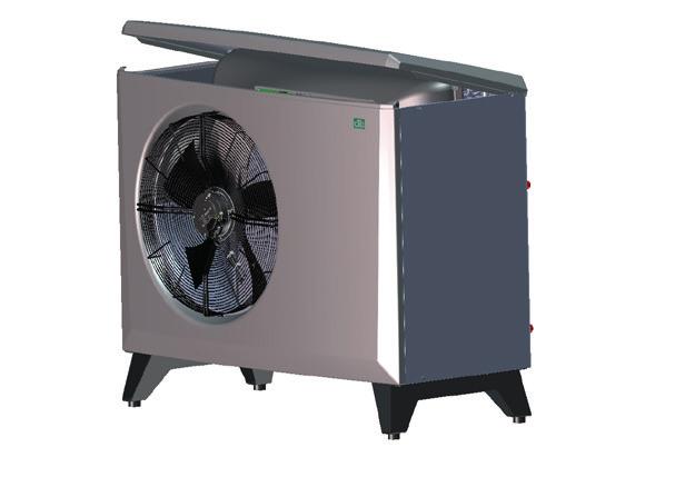
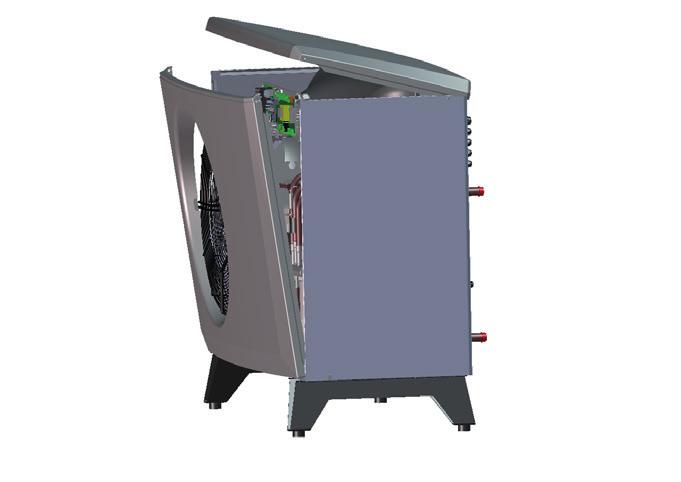

12 2.5 Component location


13 Compressor 2. 4-way valve 3. Heat exchanger 4. Expansion valve 5. High pressure sensor 6. Low pressure sensor 7. High pressure switch 8. Connection box 9. Bleeding nipple/water 10. Drying filter 11. Suction gas sensor 12. Primary flow sensor 13. Return sensor 14. Outdoor sensor 15. Hot gas sensor 16. Fan 17. Defrosting sensor in evaporator 18. Sensor on fan 19. Supply 20. Communication 21. Power supply 22. Communication product 23. Communication, series connection 24. Power supply, circulation pump 25. Communication, circulation pump 26. Type plate with serial number etc. 27. Compressor heater 13
14 3. Operation and Maintenance When the installer has installed your new heat pump, you should check together that the system is in perfect operating condition. Let the installer show you where the power switches, controls and fuses are so that you know how the system works and how it should be maintained. Bleed the radiators (depending on type of system) after around three days of operation and top up with water if required. 3.1 Defrosting The is fitted with hot gas defrosting. The heat pump checks constantly whether defrosting is needed and, if so, defrosting starts, the fan stops, the four-way valve changes direction and the hot gas goes to the evaporator instead. A hissing sound is heard as the water drains from the evaporator. When the product has defrosted, the fan starts and the hot gas goes into the condenser instead, and the heat pump returns to normal operation. 3.2 The fan The fan starts 15 seconds before the condenser and runs until the compressor stops. During defrosting the fan stops and restarts when defrosting is finished. 3.3 Maintenance A large amount of water passes through the evaporator in the CTC EcoAir 400. Leaves and other debris can get stuck and restrict the air flow. At least once year the evaporator coil should be checked and cleared of particles that block the air flow. The evaporator and outer covering should be cleaned with a damp cloth or soft brush. No other periodic maintenance or inspection is necessary. 3.4 Periodic maintenance After three weeks operation and then every three months during the first year. Then once a year: Check that the installation is free of leaks. Check that the product and system are free of air; bleed if needed. Check that the evaporator is clean. 3.5 Shut-down The heat pump is shut down using the operating switch. If there is a risk of the water freezing, ensure that there is circulation through the heat pump or drain out all the water from the. 3.6 Condensation water tray The condensation tray collects water formed on the CTC EcoAir evaporator during operation and defrosting. The condensation tray is equipped with an electric heating coil which keeps the tray free of ice when it is freezing outside. The condensation tray is located at the bottom on the back of CTC EcoAir 400. By lifting the handle and pulling it out, you can clean and inspect the condensation tray. You can buy a heating cable as an accessory and connect it to the EcoAir 400. The cable is installed in the drain pipe from the condensation tray to a frost-free drain. 14
15 4. Troubleshooting/measures The is designed to provide reliable operation and high levels of comfort, and to have a long service life. Various tips are given below which may be helpful and guide you in the event of an operational malfunction. If a fault occurs, you should always contact the installer who installed your unit. If the installer believes the malfunction is due to a material or design fault, then they will contact CTC-UK to check and rectify the issue. Always provide the product s serial number. 4.1 Air problems If you hear a rasping sound from the heat pump, check that it is properly bled. Top up with water where required, so that the correct pressure is achieved. If this noise recurs, call a technician to check the cause. 4.2 Alarms Any alarms and information texts from the are displayed in the product which is used to control it; you should therefore consult the manual for that product. 4.3 Circulation and Defrosting If the circulation between the indoor and the outdoor unit is reduced or stops, the high pressure switch is triggered. Possible reasons for this: Defective circulating pump/circulating pump too small Air in the pipes Condenser clogged Other intermediate obstructions to the water flow During defrosting the fan stops but the compressor operates and the melted snow and ice flows into the condensation tray under the heat pump. When defrosting stops, the fan starts again and initially a vapour cloud, consisting of damp air which condenses in the cold outdoor air, is created. This is perfectly normal and stops after a few seconds. If the pump heats poorly, check that no unusual ice formation has occurred. Possible reasons for this: Defective defrosting automation Lack of refrigerant (leakage) Extreme weather conditions. Remember that is an air source heat pump which gives less heat power when outdoor temperatures fall, while the heating needs of the house increase. When temperatures fall quickly, this means that you may experience a lack of heating power. 15
16 5. Installation This chapter is aimed at anyone responsible for one or more of the installations required to ensure that the product works the way the property owner wants. Take your time going through functions and settings with the property owner and answer any questions. Both you and the heat pump benefit from a user who has completely understood how the system operates and should be maintained. The installation must be carried out in accordance with current MCS standards. Refer to MIS 3005 and associated building regs Part L,F & G. The product must be connected to an expansion vessel in an open or closed system. Do not forget to flush the radiator system clean before connection.! The product must be transported and stored in an upright position. The heat pump operates with a primary flow/return temperature across the condenser of up to 65/58 C. Transportation Transport the unit to the installation site before removing the packaging. Handle the product in the following manner: Forklift Lifting band around the pallet. NB: Can only be used with the packaging on. Unpacking Unpack the heat pump when it is placed next to its installation site. Check that the product has not been damaged in transit. Report any transport damage to the carrier. Also check that the delivery is complete according to the list below. Delivery includes 1 x heat pump Connector for power supply 15 m LiYCY (TP) cable with connector for communication 16
17 6. Placement of the heat pump Place the heat pump so that noise from the compressor and fan does not disturb the surroundings. No not place the heat pump right next to a bedroom window, patio or fence. is normally placed on an outside wall. There should be a space of at least 250 mm (EcoAir ) or 400 mm (EcoAir ) between the product and the wall so that outdoor air can pass freely in through the evaporator. If the heat pump is placed in a corner, there should be a space of at least 250 mm between the side of the heat pump and the wall. Allow a space of at least 2 metres between the heat pump and any bushes etc. Take the distance to the nearest neighbour into account by checking the noise data in the noise data chapter. The recommended distance between units is 400 mm. The legs of the CTC EcoAir must stand stably on concrete blocks or similar. Use a spirit level to adjust the unit, so that it is completely level. Due to the design of the stand and the weight of the pump, it is not necessary to secure the unit to the ground or the wall. Installing the heat pump in a sheltered spot is inadvisable, and so is placing it in an outhouse or car port, because the air should flow as freely as possible through the heat pump and used air should not to be sucked into the inlet on the back. This can cause abnormal ice formation in the evaporator. If the product is in an exposed location, with extra harsh weather conditions, then a suitable covering or sheltered location is justified.! These guidelines must be followed in order for your to give the best performance. 400 mm ( ). 250 mm ( ) Rec. 400 mm Min 2 m 17
18 7. Preparation and drainage The heat pump should be positioned so that the house cannot be damaged and the condensation water can easily drain into the ground. The foundation should be of concrete blocks or similar, resting on crushed stones or gravel. Make a 'stone curb' under the heat pump. Remember that there may be up to 70 litres of condensation water a day under some conditions, from the largest model. Make a cm deep hole. Place a moisture barrier in the hole on the side against the foundations of the building Half fill the hole with crushed stones and lay concrete blocks or similar. Mark up the c/c dimension (1155/1285 ) between the blocks to match the span of the heat pump stand. Use a spirit level to ensure that the blocks are level. Place crushed stones around the blocks to achieve optimal drainage. Concrete blocks c/c mått 1155/ /551 Moisture barrier, up against the building foundations Concrete blocks Coarse crushed stone about cm deep Concrete blocks 18
19 7.1 Condensation water The condensation tray is built into the heat pump and is used to divert most of the condensation water. The tray can be connected to a suitable drain. Connection diameter: 42mm. A heating cable (available as an accessory) should be placed in the pipe to prevent refreezing. The heating cable is connected to the electrical cabinet in the (to be performed by an authorised electrician and according to applicable provisions.) If the house has a cellar, it is advisable to route the condensation water to a floor drain indoors (to be performed according to the applicable rules). The pipe should be installed with a slope towards the house and above the ground (so no other water can get into the cellar). Wall apertures should be sealed and insulated A water trap must be connected to the inside to prevent air from circulating in the pipe. If there is a stone curb, the outlet from the condensation water pipe should be placed at a frost-free depth. The condensation water may also be routed into the house drains, e.g. from the downpipes. Here a heating cable must be placed in the pipes that are not frost-free. Water trap Frost-free depth 19
20 8. Pipe installation The installation must be carried out in accordance with current MCS standards. Refer to MIS 3005 and associated building regs Part L,F & G. The boiler must be connected to an expansion vessel in an open or closed system. Do not forget to flush the radiator system clean before connection. 8.1 Pipe connection Return lines of at least 22 mm (for ) and 28 mm (for ) copper pipe are connected to the heat pump. For longer pipes, the installer should calculate the pump and pipe dimensions needed to handle the minimum recommended flow for the concerned. Route the pipes between the heat pump and the boiler without any highest points. If this cannot be done, provide this highest point with an automatic air separator or and in line aerator. The connection to the heat pump should be made with a wirereinforced diffusion-tight hose for hot water, min. 1 diameter. Recommended hose length 1000 mm, to prevent noise from the heat pump spreading into the house and to take up any movement of the heat pump Pipes installed outside should be insulated with at least 13 mm thick insulation which is not sensitive to water. Ensure that the insulation is sealed tightly everywhere and that joints are thoroughly taped or glued. Indoor pipes should be insulated as far as the boiler with at least 9 mm thick insulation. This is to enable the heap pump to deliver the highest possible temperature to the boiler or tank without any losses. The product can be bled via the bleed valve inside the condenser.! Do not forget to flush the radiator system clean before connection.! NOTE! Bleed only on this valve. The others are for the cooling system, If these are opened, refrigerant can leak! Pressure differential diagram for Pressure differential (kpa) EcoAir 406 EcoAir 408 EcoAir 410 EcoAir EcoAir ,1 0,2 0,3 0,4 0,5 0,6 0,7 Water flow (l/s) 20

21 8.2 Example pipe connection EcoAir/EcoZenith i250 L The CTC EcoZenith i250 L has pipes at the rear right edge for connection of the heat pump. The heat pump s lower connection is connected to the right connection when viewed from the front, so that water is pumped out to the heat pump. The heat pump s upper connection is thus connected to the left connection. 1. Wire-reinforced diffusion-tight hose for hot water, min. 1. Hose length 1000 mm from the unit. 2. Outgoing (heated) water ø28 mm connection on the condenser. 3. Incoming (cold) water ø28 mm connection on the condenser. 4. Minimum ø22 copper pipe insulated outside with 13 mm thick insulation. 5. Inside piping is insulted with 9 mm thick insulation 6. Bleeder EcoAir/EcoZenith i250 H On the CTC EcoZenith i250 H, the heat pump is connected directly to the charge pump located under the tank. The heat pump s lower connection must be connected to the charge pump so that water is pumped out to the heat pump. The heat pump s upper connection is connected to the right diverting valve by the charge pump.! For optimum performance insulate outdoor and indoor piping as recommended in the instructions. 21
22 9. Circulation pump The choice of circulation pump depends on the type of system. Ensure that the circulation pump is large enough, so that there is sufficient flow through the heat pump. The circulation pump may be connected either internally within the or externally in the controlling unit. The charge pump supplies the with water. If the outdoor temperature is below + 2 C the charge pump runs constantly to eliminate any risk of freezing. If the product installed at a facility where power outages can occur, then it is advisable to supplement with an emergency power generator for the charge pump. Or to install mechanical frost protection. Internal connection. With internal connection, the flow through the circulation pump is controlled by the controller in the. The control system for the CTC EcoAir 400 monitors and ensures that the unit is working within its operating range. For optimum performance, choose one of the A-class circulation pumps below. CTC EcoAir Yonos Para PWM 7,0 Item no CTC EcoAir 410 Yonos Para PWM 7,5 Item no CTC EcoAir UPM GEO Item no External connection With external connection, a circulation pump is installed so that the right flow through the heat pump can be guaranteed. Set the right temperature differential by adjusting the speed of the circulation pump. This is to ensure that the right differential for the current outdoor temperature is produced according to the table. Outdoor temp. ( C) CTC EcoAir 406 Primary flow 35 C Flow = 0.21 l/s 4 C 4,5 C 5,5 C 6,5 C 7 C 8 C CTC EcoAir 408 Primary flow 35 C Flow = 0,27 l/s 4 C 4,5 C 5,5 C 6,5 C 7 C 7,5 C CTC EcoAir 410 Primary flow 35 C Flow = 0.39 l/s 4 C 5 C 6 C 6.5 C 7 C 8 C CTC EcoAir 415 Primary flow 35 C Flow = 0.55 l/s 4 C 4.5 C 5.5 C 6.5 C 7 C 7.5 C CTC EcoAir 420 Primary flow 35 C Flow = 0.64 l/s 4 C 4.5 C 5.5 C 6.5 C 7 C 7.5 C In some systems with EcoLogic, the entire radiator flow must go through the heat pump, so the pump must be sized according to the flow of the whole system. For safe operation, the following flow must be maintained: CTC EcoAir 406: 760 l/tim CTC EcoAir 408: 960 l/tim CTC EcoAir 410: 1400 l/hr CTC EcoAir 415: 2000 l/hr CTC EcoAir 420: 2300 l/hr This provides about: 7 C temperature differential with an outside temperature of +7 C and a primary flow temperature of 35 C 22
23 9.1 Control/supply CTC EcoZenith i550 Pro The circulation pump is controlled and powered from the CTC EcoZenith i550pro. For more information, see the relevant product manual. CTC EcoZenith i250 The circulation pump is factory-installed in the CTC EcoZenith i250. Control and supply take place from the product. For more information, see the relevant product manual. CTC EcoLogic PRO Up to 10 heat pumps can be connected to a CTC EcoLogic PRO. The circulation pumps in heat pumps 1 and 2 can then be connected to the CTC EcoLogic PRO. The circulation pumps for heat pumps 3-10 should be connected to the. CTC EcoLogic v3 The circulation pump (not speed-controlled) is controlled and powered from the. CTC EcoZenith v3 The circulation pump (not speed-controlled) is controlled and powered from the. CTC EcoEl v3 The circulation pump (not speed-controlled) is controlled and powered from the. Standalone operation The circulation pump is connected to the and controlled using the CTC Basic Display 9.2 Operating range The control system for the monitors and ensures that the unit is working within its operating range. flow line temp outdoor temp 23
24 10. Electrical installation The installation and heat pump connection must be done by an authorised electrician. All wiring must be installed according to valid requirements Communication connections The communication cable used is an LiYCY (TP) which is 4-conductor shielded cable, where the communication-bearing conductors are of twisted pair type. Use of any other cable will mean that the conductor colours may not match, necessitating a check that the colours of the conductors from unit 1 are connected to the same colours in unit 2. The machine may also be more sensitive to faults if the wrong cable is used. Connect the communication cable here Installing 1 heat pump When installing 1 heat pump, dip-switch 2 should be set to the ON position. ON ON 1 2 ON
25 10.2 Series connection of heat pumps In a series connection dip switch 2 must be turned OFF on all heat pumps except the last one, which should be set to the ON position.. ON ON ON ON OFF OFF OFF ON ndr. meddel. Datum Nr Ändring Ändr. av Kontr. av Connecting communication in series (grey connector) The communication cable used is an LiYCY (TP). In the grey connector the heat pumps are connected in series. 1. Connect the next pump in the connection chain in the gray connector Brown 2. White 3. Green 4. Shield 5. NB! Yellow cable is not used. Existing cable Connect next heatpump here. 2. Remove the lid from the electrical box in the heat pump ill/antal het RA 1:1 Tol.system Ersätter art. nr in the connection chain. Ersättes av art. nr Ämnes nr E 3. Move the PE-cable from terminal 4 to 5 on all heat pumps, except the last Om ej annat angives gäller ovanstående Benämning l Grupp Produkt Ritad Kontr. Normgr. Godk. prod Reg. nr Utgåva blad 1/1 25
26 10.4 Electrical installation 400V 3N~ Supply, black connector The must be connected to 400V 3N~ 50 Hz and protective earth. The minimum group fuse size is specified in 'Technical data'. Recommended cable ( ) 400V 3N~ Ölflex 110 black 5G 1,5. Recommended cable ( ) 400V 3N~ Ölflex 110 black 5G 2,5. Safety switch The installation should be preceded by a omnipolar safety switch (Category III), which ensures disconnection from all electric power sources Electrical installation 230V 1N~ Supply, black connector The must be connected to 230V 1N~ 50 Hz and protective earth. The minimum group fuse size is specified in 'Technical data'. Recommended cable 230V 1N~ Ölflex 110 black 3G 4.0. Safety switch The installation should be preceded by a dual pole isolating safety switch which ensures disconnection from all electric power sources Connection for subsequent connectors We recommend pulling the cable through the cable clip before you connect the wires. The cable clip can also be fitted afterwards. (See figure 1) a. Outer sleeve stripped to 55mm b. Wires stripped to 9mm c. Advanced protective earth wires stripped to 7mm Open the terminal block by pushing a screwdriver (blade width 2.5mm) into the block. Connect the stripped wires in the specified positions. Check that only the stripped parts are clamped to the terminals, NO INSULATION! (See figures 2,3) Fix the cable clip to the connector. The word TOP should be visible on the terminal and the cable clip (see figure 4) Push the cable clip onto the connector. Then tighten the screw to obtain the desired tension. (See figures 5) Figure 1 Figure 2 Figure 3 Figure 4 Figure 5 26
27 10.3 CTC Basic Display (accessory) The heat pump can be run without a controlling system (standalone), but it must be supplemented with the CTC Basic Display accessory. For the Basic control, a PVM pump is recommended as a charge pump. The charge pump is connected to the, which then controls the pump. The charge pump can also be connected at a constant fixed voltage. Then a pump with manual speed adjustment must be used. See CTC Basic Display manual for more information Connection Connecting the CTC Basic Display (accessory) ON CTC Basic Display (accessory) 1 2 ON ON 1 2 To be able to control your heatpump with CTC Basic display make sure that dipswitch 1 is set to ON. see image Alarm output The is fitted with a potential-free alarm output which is activated if any alarm is active in the heat pump. This output may be connected to a maximum load of 1 A 250 V AC. An external fuse should also be used. Cable approved for 230 V AC must be used for connecting this output, irrespective of the load that is connected. For connection information, see the wiring diagram. Detailed view from wiring diagram. 27
28 11. Connecting the control system 11.1 General When connecting the to products with different control systems, accessories are sometimes needed to control the products. The various alternatives available are described in this section Connection alternative 1 CTC EcoZenith i250/ctc EcoZenith i550 Pro When connecting a to a CTC EcoZenith i250, CTC EcoZenith i550 Pro and CTC EcoLogic Pro, the communication cable (LiYCY (TP)) is connected directly to each product Connection alternative 2 CTC EcoLogic Pro When connecting more than one heat pump to a CTC EcoLogic Pro, the CTC Basic Display accessory must be used to address the various heat pumps A1, A2, A3, etc. All units are factory-set addressed to A1. For connection, see the manual for the CTC Basic Display. Recommended cable between products LiYCY (TP).! When connected in series, the last heat pump must be set to the terminated position. Read more under the chapter Electrical installation/ Terminated position CTC EcoLogic Pro CTC Basic Display 28
29 11.4 Connection alternative 3 CTC Basic Display The can be operated based on an existing boiler via the CTC Basic Display accessory. This can be done with a fixed temperature (fixed condensing) or based on thermostatic control. Given that the standard version of the does not have its own controller, the CTC Basic Display accessory is required. For connection, see the manual for the CTC Basic Display. Recommended cable between products LiYCY (TP). CTC Basic Display!A CTC Basic Display (accessory) is only needed when the does not have its own control system as in connection alternative 3, or when more than one heat pump is present it is then needed for correct addressing of the heat pumps A1, A2, A3, etc. 29
30 ON RS485 TX RS485 RX COM TX COM RX General Information 11.5 Connection alternative 4 CTC EcoEl v3 Because these products have an older control system of v3 type, the CTC Converter accessory must be used as an interpreter to control the CTC EcoAir 400. See the manual for the CTC Converter for connecting this.!version 3 (V3) relates to models manufactured from 2006 onwards. CTC EcoEl V3 CTC E V CTC Converter 30
31 ON RS485 TX RS485 RX COM TX COM RX General Information 11.6 Connection alternative 5 CTC EcoZenith v3 or CTC EcoLogic v3 Because these products have an older control system of v3 type, the CTC Converter accessory must be used as an interpreter to control the CTC EcoAir 400. See the manual for the CTC Converter for connecting this.!version 3 (V3) relates to models manufactured from 2006 onwards. The CTC EcoZenith version 3 is available in two different variants. An earlier variant with only one communication port, and a later one with three such ports. The earlier one will have a serial number starting from: Prod. no. Item no. Model CTC EcoZenith I 550 3x400V CTC EcoZenith I 550 3x230V CTC EcoZenith I 550 BBR CTC EcoZenith I 550 1x230V The earlier version needs a Converter to control the heat pump. CTC EcoZenith V3 CTC EcoLogic V3! If new (version 4) and old (version 3) heat pumps are combined in an installation, the new one must be addressed A1. CTC Converter CTC EcoAir V3!When connected in series, the last CTC EcoAir 400 must be set to the terminated position. 31
32 ON RS485 TX RS485 RX COM TX COM RX ON RS485 TX RS485 RX COM TX COM RX ON RS485 TX RS485 RX COM TX COM RX General Information 11.7 Connection alternative 6 CTC EcoZenith I 550 The CTC EcoZenith version 3 is available in two different variants. An earlier variant with only one communication port, and a later one with three such ports. The later one will have a serial number starting from: Prod. no. Item no. Model CTC EcoZenith I 550 3x400V CTC EcoZenith I 550 3x230V CTC EcoZenith I 550 BBR CTC EcoZenith I 550 1x230V For the later variant a CTC Converter is needed for each version 4 heat pump. See the manual for the CTC Converter for connection. CTC EcoZenith V3 CTC Converter CTC Converter CTC Converter 32
33 11.8 Parts list A2 A4 B1 B7 B15 B16 B20 B21 B22 B100 B101 C1 C2 E10 E11 E12 F1 F20 G11 K1 M1 M10 X1 XM1 XM2 XC1 XC2 Y10 Y11 Relay/main PCB PCB white softstarter, motorprotection and contactorfunction Primary flow sensor Return sensor Outdoor sensor Defrost sensor Air sensor Hotgas sensor Suctiongas sensor Highpressure sensor Lowpressure sensor Capacitor compressor (1-phase) Capacitor Compressor heater Vaporizer heater Heating cable (option) Fuse (option) Highpressure switch Loadpump (option) Contactor (EA ) Compressor Fan Terminal Connector supply Male Connector supply Female Connector communication Male Connector communication Female Expansion valve Solenoid valve 33
34 11.9 Wiring diagram 400 V 3N~ Communication (Grey connector) Supply (Black connector) 34
35 Ω Ω Ω Ω Ω Ω Ω Ω Ω 35
36 11.10 Wiring diagram 230V 1N~ Communication (Grey connector) Supply (Black connector) 36
37 37
38 12. First start 1. Check that the boiler and system are full of water and have been bled. 2. Check that all connections are tight. 3. Check that sensors and the charge pump are connected to the power source. 4. Energise the heat pump by switching on the safety switch (the main switch). Once the system has heated up, check that all connections are tight, the various systems have been bled, heat is coming out into the system and warm water is coming out at the tap locations. 13. Noise data Standard Model Noise level Noise pressure 5 m* Noise pressure 10 m* EcoAir db(a db(a db(a EcoAir db(a db(a db(a EcoAir db(a) db(a) db(a) EcoAir db(a) db(a) db(a) EcoAir db(a) db(a) db(a) Silent mode Model Noise level Noise pressure 5 m* Noise pressure 10 m* EcoAir db(a) db(a) db(a) EcoAir db(a) db(a) db(a) * The given noise pressure should be taken as an indication as the level is affected by the surroundings. The upper value corresponds to 100% reflecting ground and walls (smooth concrete).values according to EN Silent mode The CTC EcoAir 415 and 420 can be set to 'silent mode' by their respective control systems. In this position, the fan runs at a lower speed which means that the product makes less noise. The stated output will then be reduced by a few percent, depending on the operating situation. 38
39 13.1 Sensor data NTC 22 kω Temperature C NTC 22 kω Resistance Ω Hot gas sensor Temperature C Hot gas sensor Resistance Ω Suction gas sensor Temperature C Suction gas sensor Resistance Ω


40 Enertech AB Box 313 S LJUNGBY 14. Declaration of conformity Försäkran om överensstämmelse Déclaration de conformité Declaration of conformity Konformitätserklärung försäkrar under eget ansvar att produkten, confi rme sous sa responsabilité exclusive que le produit, declare under our sole responsibility that the product, erklären in alleiniger Verantwortung, dass das Produkt, Typ, Type EA 400 som omfattas av denna försäkran är i överensstämmelse med följande direktiv, auquel cette déclaration se rapporte est en conformité avec les exigences des normes suivantes, to which this declaration relates is in conformity with requirements of the following directive, auf das sich diese Erklärung bezieht, konform ist mit den Anforderungen der Richtlinie, EC directive on: Pressure Equipment Directive (PED) 97/23/EC, Modul A Electromagnetic Compatibility (EMC) 2004/108/EC Low Voltage Directive (LVD) 2006/95/EC Ecodesign Directive 2009/125/EC (regulations (EU) 811/2013, 812/2013, 813/2013, 814/2013 where applicable) Överensstämmelsen är kontrollerad i enlighet med följande EN-standarder, La conformité a été contrôlée conformément aux normes EN, The conformity was checked in accordance with the following EN-standards, Die Konformität wurde überprüft nach den EN-normen, EN A1, -A2 / -2-3 EN , -4, -5, -6, -11 EN :2006, A1:2009, A2:2009, EN :2008 EN / EN 378 EN Detailed ecodesign information can be downloaded at: Ljungby Joachim Carlsson Technical Manager 40
41
42
43
44 Enertech AB. P.O Box 309 SE Ljungby Sweden.
Installation- and Maintenance Manual CTC EcoAir 520M. Modulating air/water heat pump. Providing sustainable energy solutions worldwide
 162 105 43-1 2015-06-18 Providing sustainable energy solutions worldwide Installation- and Maintenance Manual Modulating air/water heat pump Installation and Maintenance Manual Modulating air/water heat
Installation- and Maintenance Manual CTC EcoAir 500M. Modulating air/water heat pump. Providing sustainable energy solutions worldwide
 162 105 54-1 2015-08-21 Providing sustainable energy solutions worldwide Installation- and Maintenance Manual CTC EcoAir 500M Modulating air/water heat pump Installation and Maintenance Manual CTC EcoAir
Installation- and Maintenance Manual CTC EcoAir 510M. Modulating air/water heat pump 400V 3N~ Providing sustainable energy solutions worldwide
 162 105 63-1 Providing sustainable energy solutions worldwide Installation- and Maintenance Manual CTC EcoAir 510M Modulating air/water heat pump 400V 3N~ IMPORTANT READ CAREFULLY BEFORE USE KEEP FOR FUTURE
CTC EcoAir. Installation and Maintenance Manual. Model 406 I 408 I 410 I 415 I 420 Air source heat pump 400V 3N~/ 230V 1N~
 162 205 51-2 2018-08-31 Providing sustainable energy solutions worldwide Installation and Maintenance Manual CTC EcoAir Model 406 I 408 I 410 I 415 I 420 Air source heat pump 400V 3N~/ 230V 1N~ IMPORTANT
CTC EcoMiniEl. Installation- and Maintenance Manual. External electric boiler. Providing sustainable energy solutions worldwide
 161 505 34-3 2015-09-18 Providing sustainable energy solutions worldwide Installation- and Maintenance Manual External electric boiler 161 505 34-3 2015-09-18 Installation- and Maintenance Manual External
CTC EcoAir 510M. Installation- and Maintenance Manual. Modulating air/water heat pump 230 V 1N~ Providing sustainable energy solutions worldwide
 162 205 72-3 2019-01-10 Providing sustainable energy solutions worldwide Installation- and Maintenance Manual CTC EcoAir 510M Modulating air/water heat pump 230 V 1N~ IMPORTANT READ CAREFULLY BEFORE USE
Installation and Maintenance Manual CTC EcoPart 400. Model V 3N~ / 230V 1N~ Providing sustainable energy solutions worldwide
 162 105 51-2 2015-09-15 Providing sustainable energy solutions worldwide Installation and Maintenance Manual Model 406-417 400V 3N~ / 230V 1N~ Removing the cooling module 1. Disconnect the cooling module
Installation and Maintenance Manual CTC EcoPart 400. Model V 3N~ / 230V 1N~ Providing sustainable energy solutions worldwide
 162 105 32-2 2014-05 12 Providing sustainable energy solutions worldwide Installation and Maintenance Manual Model 406-417 400V 3N~ / 230V 1N~ Removing the cooling module 1. Disconnect the cooling module
Providing sustainable energy solutions worldwide. Installation and Maintenance Manual. CTC EcoPart XL.
 162 105 18-3 2014-11-26 Providing sustainable energy solutions worldwide Installation and Maintenance Manual Model 424-434 Removing the cooling module 1. Disconnect the cooling module s power cable connector
CTC EcoZenith C 530 l 510
 Installation and Maintenance Manual CTC EcoZenith C 530 l 510 161 505 77/1 2010-02-18 Table of Contents For the property owner Welcome... 3 Important to remember!... 4 Safety Instructions... 4 Hot water...
Installation and Maintenance Manual CTC EcoPart i425-i435 Pro CTC EcoPart
 162 105 38-1 2014-08-14 Providing sustainable energy solutions worldwide Installation and Maintenance Manual CTC EcoPart i425-i435 Pro CTC EcoPart 425-435 Removing the cooling module 1. Disconnect the
Installation and Maintenance Manual CTC EcoPart i425-i435 Pro CTC EcoPart
 162 105 52-1 2015-05-21 Providing sustainable energy solutions worldwide Installation and Maintenance Manual CTC EcoPart i425-i435 Pro CTC EcoPart 425-435 Removing the cooling module 1. Disconnect the
CTC EcoPart 400. Installation and Maintenance Manual. Model V 3N~ / 230V 1N~ Providing sustainable energy solutions worldwide
 162 205 01-1 2017-05-30 Providing sustainable energy solutions worldwide Installation and Maintenance Manual Model 406-417 400V 3N~ / 230V 1N~ IMPORTANT READ CAREFULLY BEFORE USE KEEP FOR FUTURE REFERENCE
/ Installation and Maintenance Manua. CTC EcoAir. Model 105 I 107 I 110 Polar Edition 107 I 110. Air/Water Heat Pump
 161 505 87/1 2010-12 29 Installation and Maintenance Manua CTC EcoAir Model 105 I 107 I 110 Polar Edition 107 I 110 Air/Water Heat Pump Installation and Maintenance Manual CTC EcoAir 105 I 107 I 110 CTC
CTC EcoComfort. Installation and Maintenance Manual. for the property owner. Providing sustainable energy solutions worldwide
 162 105 25-2 2015-11-16 Providing sustainable energy solutions worldwide Installation and Maintenance Manual CTC EcoComfort for the property owner IMPORTANT READ CAREFULLY BEFORE USE KEEP FOR FUTURE REFERENCE
OPERATING INSTRUCTIONS
 OPERATING INSTRUCTIONS Dust Extractor T12600 READ ALL INSTRUCTIONS BEFORE USING Dear Customer. Thank you for choosing Ermator as your supplier. Introduction We hope that the Ermator dust extractor will
OPERATING INSTRUCTIONS
 OPERATING INSTRUCTIONS Dust Extractor S13 READ ALL INSTRUCTIONS BEFORE USING Introduction Dear Customer, Thank you for choosing Ermator as your supplier. We hope that the Ermator S13 dust extractor will
Planning guide. Atec.
 www.thermia.com Thermia Värmepumpar is not liable or bound by warranty if these instructions are not adhered to during installation or service. The English language is used for the original instructions.
Installation instructions Danfoss heat pump DHP-R
 Installation instructions Danfoss heat pump DHP-R Table of contents DHP-R 1 Important information........................................................... 5 1.1 Refrigerant...5 1.2 Noise and vibrations...5
HT V2 HT Split
 Scroll compressor Refrigerant R07C Aqu@Scop HT V Aqu@Scop HT Split High Temperature Air-to-Water Heat Pumps Models -, -7 and 8-9.0 to 7.9kW Aqu@Scop HT V / Aqu@Scop HT Split Installation examples - Single
NIBE F2026 air/water heat pump. fresh air s free. NIBE F2026. Efficient scroll compressor that operates at temperatures down to -20 C.
 NIBE F2026 air/water heat pump fresh air s free. Efficient scroll compressor that operates at temperatures down to -20 C. Automatic 2-step capacity regulator for the fan (not 6kW). Manufactured in three
The CE Marking Access to the European Market
 The CE Marking Access to the European Market The EU dictates the compliance of guidance and a CE marking for many industrial products, so that these products may attain to the market. The experts of Eurofins
AGEO CALEO. Water-to-water high temperature heat pumps USE RANGE DESCRIPTION. Designed to replace a conventional boiler and produce domestic hot water
 Designed to replace a conventional boiler and produce domestic hot water Heating capacity : 16 to 25 Heating Hydraulic module ENVIRONMENTALLY HFC R4A PROTECTION DE FRIENDLY L'ENVIRONNEMENT USE CIAT is
CTC EcoZenith i350 L/H Indoor module with heat pump control available in two heights
 CTC EcoZenith i30 L/H Indoor module with heat pump control available in two heights Ultra-efficient indoor module available in two heights with many options and built-in heat pump control. CTC EcoZenith
Technical description. Atec.
 www.thermia.com Thermia Värmepumpar is not liable or bound by warranty if these instructions are not adhered to during installation or service. The English language is used for the original instructions.
1 SAFETY REPAIR COMPONENTS FUNCTIONS FAULT DIAGNOSIS X-Cool Side by Side Refrigerator
 1 SAFETY... 3 1.1 Safety instructions... 3 1.2 Repair instructions... 3 2 COMPONENTS... 4 2.1 Overall view... 4 2.2 Compressor room... 4 2.3 Power Control Boards (PCB)... 5 2.4 Temperature sensor... 6
Installation- and maintenance instruction CTC EcoEl. Model 1550 and Providing sustainable energy solutions worldwide
 161 505 80-3 2012-09-20 161 421 50 10-01 Providing sustainable energy solutions worldwide Installation- and maintenance instruction Model 1550 and 1800 Enertech AB. P.O Box 309 SE-341 26 Ljungby Sweden.
OWNER S MANUAL. Vintage Signature Series models: AC750, AC1050, AC1100, AC1250, AC1500, AC1750. Proudly Made in the USA.
 OWNER S MANUAL Vintage Signature Series models: AC750, AC1050, AC1100, AC1250, AC1500, AC1750 Proudly Made in the USA support@aquacomfort.com 888-475-7443 Manufacturing High Quality, High Efficiency Heat
MODULAR AUTOMATIC GRANULAR ICE FLAKER
 MODULAR AUTOMATIC GRANULAR ICE FLAKER INSTRUCTIONS AND WARNINGS 24479 rev. 03 It is strictly forbidden to reproduce this instruction manual or any part thereof. Dear Customer, Congratulations on having
Split inverter air-to-water heat pump CERTIFIED BY CERTITA. option 30/35-40/45
 Plug & Heat heat pump Quick and easy to install For new homes or boiler backup operation 50 HFC R410A CERTIFIED BY CERTITA Heating capacity: 5.5 to 22 kw option CERTIFIED BY CERTITA 30/35-40/45 USE The
Technical manual NIBE AG-AA10 Single split air to air heat pump
 Technical manual NIBE AG-AA10 Single split air to air heat pump TABLE OF CONTENTS 1 SCOPE... 4 2 DIMENSIONAL DATA AND EXTERIOR APPEARANCE... 5 3 TECHNICAL SPECIFICATIONS... 7 4 REFRIGERANT CIRCUIT... 10
Swedish design and manufacture since 1967
 Swedish design and manufacture since 167 PVP MA20-14 rev.2 Manual User manual Copyright 2017 Pahlén AB, Box 728, SE-14 27 Upplands Väsby, Sweden Tel. +46 8 54 110 50, Fax +46 8 50 868 80, e-mail: info@pahlen.se,
Installer manual AG-AA10. Air/air heat pump IHB GB AG-AA10-30 AG-AA10-40/50
 -30 Installer manual Air/air heat pump -40/50 IHB GB 1516-1 331554 Table of Contents 1 Important information 2 5 Installation 7 Safety information 2 Model combinations 7 Read before starting the installation
Providing sustainable energy solutions worldwide. Installation and Maintenance Manual CTC EcoHeat V 3N~ / 230V 1N~
 162 105 30-2 2013-09-23 Providing sustainable energy solutions worldwide Installation and Maintenance Manual CTC EcoHeat 400 400V 3N~ / 230V 1N~ Removing the cooling module 1. Disconnect the cooling module
PRODUCT DATA COMFORT 450 BY NILAN. Ventilation & passive heat recovery. Passive heat recovery. < 450 m 3 /h
 PRODUCT DATA COMFORT 40 BY NILAN Ventilation & passive heat recovery Domestic Passive heat recovery Ventilation < 40 m /h COMFORT 40 Product description The Comfort 40 is an energy-efficient ventilation
CTC EcoZenith i350 Indoor module with heat pump control available in two heights
 CTC EcoZenith i30 Indoor module with heat pump control available in two heights Ultra-efficient indoor module available in two heights with many options and built-in heat pump control. CTC EcoZenith i30
Manual Isolating Barrier D461R1 (Revision 01)
") D461R1 Manual Isolating Barrier D461R1 (Revision 01) Product Manual Original Instructions valid for models D461R1.11 with 1x signal input into 1x isolated signal output D461R1.12 with 1x signal input into
D461R1 Manual Isolating Barrier D461R1 (Revision 01) Product Manual Original Instructions valid for models D461R1.11 with 1x signal input into 1x isolated signal output D461R1.12 with 1x signal input into
CTC EcoZenith i250 Indoor module with heat pump control available in two heights
 CTC EcoZenith i50 Indoor module with heat pump control available in two heights The flexible indoor module with touchscreen and EnergyFlex. An efficient indoor module available in two heights with ample
NIBE F2120 Air/water heat pump
 NIBE Air/water heat pump A breakthrough in efficiency NIBE is an air/water heat pump that has made a real breakthrough with a market leading SCOP. utilises the heat from the outdoor air which places big
TECHNICAL MANUAL CX(E) SPLIT SYSTEMS. Tel: Fax:
 SPLIT SYSTEMS. Tel: Fax:") TECHNICAL MANUAL CX(E) SPLIT SYSTEMS CONTENTS INDEX PART NUMBERS, OPTIONS, UNIT COMBINATIONS, DIMENSIONS & WEIGHTS 3 PERFORMANCE DATA & AIR FLOW 4 SOUND POWER AND SOUND PRESSURE LEVELS 5 ELECTRICAL DATA
TECHNICAL MANUAL CX(E) SPLIT SYSTEMS CONTENTS INDEX PART NUMBERS, OPTIONS, UNIT COMBINATIONS, DIMENSIONS & WEIGHTS 3 PERFORMANCE DATA & AIR FLOW 4 SOUND POWER AND SOUND PRESSURE LEVELS 5 ELECTRICAL DATA
PHRIE / PHIE InvERTER monoblock air To water HEaT PumP medium TEmPERaTuRE
 TEcHnIcal InsTRucTIons PHRIE / PHIE InvERTER monoblock air To water HEaT PumP medium TEmPERaTuRE PHRIE 095 PHRIE 1 PHIE 095 PHIE 1 PHRIE 155 PHRIE 157 PHRIE 175 PHRIE 177 PHRIE 195 PHRIE 197 PHRIE 7 PHRIE
AUTOMATIC GRANULAR ICE FLAKER
 AUTOMATIC GRANULAR ICE FLAKER INSTRUCTIONS AND WARNINGS 24480 rev. 01 It is strictly forbidden to reproduce this instruction manual or any part thereof. Dear Customer, Congratulations on choosing a
INSTALLATION AND USER MANUAL
 INSTALLATION AND USER MANUAL t Thank you for choosing Aqua inverter heat pump. This manual provides you necessary information for optimal use and maintenance, please read it carefully and keep it for subsequent
CTC EcoZenith i550 Pro All-in-one tank with built-in, intelligent control.
 CTC EcoZenith i550 Pro ll-in-one tank with built-in, intelligent control. CTC EcoZenith i550 Pro can control all components in one or more heating systems: solar heating, pool, extra hot water, buffer
INSTRUCTION MANUAL (English version) Water still
 Water still") INSTRUCTION MANUAL (English version) Water still Model : Brand : W4000 Merit Merit Water Still W4000 & W4000/EURO Cooling water inlet Condenser Constant level control Boiler Thermostat reset buttons To
INSTRUCTION MANUAL (English version) Water still Model : Brand : W4000 Merit Merit Water Still W4000 & W4000/EURO Cooling water inlet Condenser Constant level control Boiler Thermostat reset buttons To
NIBE SPLIT ACVM 270 Air/water heat pump
 NIBE SPLIT ACVM 270 Air/water heat pump NIBE SPLIT ACVM 270 system with complete indoor module NIBE SPLIT ACVM 270 is a complete modern heat pump system that offers effective technical energy saving and
DL/DLM. Operating instructions Manuel d instructions Instrucciones de uso
 DL/DLM Operating instructions Manuel d instructions Instrucciones de uso Scope of delivery for DL/DLM: 1. DL/DLM 2. AAA batteries 3. Quick start guide 4. Device bag 1. 3. 2. 4. 2 DL/DLM operating manual
OWNER S MANUAL. Models: AC110, AC125, AC150 made from 2003 through Proudly Made in the USA
 OWNER S MANUAL Models: AC110, AC125, AC150 made from 2003 through 2010 Proudly Made in the USA support@aquacomfort.com www.aquacomfort.com/service-and-support/ (888) 475-7443 Manufacturing High Quality,
AUTOMATIC MODULAR ICE FLAKER
 AUTOMATIC MODULAR ICE FLAKER INSTRUCTIONS AND WARNINGS 24479 rev. 08 It is strictly forbidden to reproduce this instruction manual or any part thereof. 1 5 3 4 Mod. N. V. W 2 2 M8 18 8 18 M8 M8 3 ~ 200
End customer overview
 16210568-1 2016-08-23 End customer overview Indoor module with heat pump control 1. Sign the installation checklist. 2. Serial no. behind touchscreen. 3. Bleed radiator system and products, approx. one
F17W44_MFB_F_EN INSTALLATION INSTRUCTIONS
 F17W44_MFB_F_EN INSTALLATION INSTRUCTIONS Contents Page User instructions 3-5 General 3 Fan installation 3-4 Maintenance 3 Electrical installation 5 Troubleshooting 5 Technical description 6-8 General
High temperature air-to-water heat pumps
 Designed to replace conventional boilers and produce domestic hot water 4 High temperature hot water (+65 C) 4 Winter operation (-20 C) 4 High energy efficiency (CP) 4 Compact and quiet 4 Scroll compressors
LK Electric Boiler - 4,5
 LK Electric Boiler -, Design LK Electric Boiler, kw is a wall-mounted electric boiler, intended primarily for low-temperature heating systems, e.g. under floor heating. LK Electric Boiler, kw is delivered
Manual Isolating Barrier D461 (Revision 05)
") D461 Manual Isolating Barrier D461 (Revision 05) Product Manual Original Instructions valid for models D461.11 with 1x signal input into 1x isolated signal output D461.12 with 1x signal input into 2x isolated
D461 Manual Isolating Barrier D461 (Revision 05) Product Manual Original Instructions valid for models D461.11 with 1x signal input into 1x isolated signal output D461.12 with 1x signal input into 2x isolated
Warning: 230V / 1ph / 50Hz V / 3ph / 50Hz. Remarks: Make sure that you have enough power. (See page 15 Cable table)
") 1 2 Warning: - Do not place your hand or any other objects into the air outlet and fan. It could damage the heat pump and cause injuries; - In case of any abnormality with the heat pump, cut off the power
1 2 Warning: - Do not place your hand or any other objects into the air outlet and fan. It could damage the heat pump and cause injuries; - In case of any abnormality with the heat pump, cut off the power
AUTOMATIC MODULAR ICE-CUBE MAKER WITH VERTICAL EVAPORATOR SYSTEM
 AUTOMATIC MODULAR ICE-CUBE MAKER WITH VERTICAL EVAPORATOR SYSTEM INSTRUCTIONS AND WARNINGS 24481 ed. 11-2007 It is strictly forbidden to reproduce this instruction manual or any part thereof. Dear
INSTALLATION, COMMISSIONING AND OPERATING MANUAL
 INSTALLATION, COMMISSIONING AND OPERATING MANUAL 1 YTBV-D-CE42_0109 CONTENT Available models and capacities Supplier information Warranty Safety Emergency stops/ shutdowns About this manual Models Physical
CHGV AIR COOLED WATER CHILLER WITH HYDRAULIC EQUIPMENT AIR / WATER 47 to 78 kw
 TECHNICAL INSTRUCTIONS CHGV AIR COOLED WATER CHILLER WITH HYDRAULIC EQUIPMENT AIR / WATER 47 to 78 kw CHGV 50 CHGV 64 CHGV 72 CHGV 80 PHRV heat pump model also available November 2007 10 12 167 - GB -
CHGV AIR COOLED WATER CHILLER WITH HYDRAULIC EQUIPMENT AIR / WATER 21 to 39 kw
 TECHNICAL INSTRUCTIONS CHGV AIR COOLED WATER CHILLER WITH HYDRAULIC EQUIPMENT AIR / WATER 21 to 39 kw CHGV 22 CHGV 2 CHGV 32 CHGV 40 PHRV heat pump model also available September 2007 10 12 11 - GB - 02
Installation, operating and servicing instructions
 English 57-115 - 144-1 - 259 Installation, operating and servicing instructions ITALIA EN 1 ITALIA English INDEX WARnINGS 3 Who should read these instructions 3 Symbols 3 Recommendations 3 Importants notes
PRODUCT DATA COMFORT 600 BY NILAN. Ventilation & passive heat recovery. Passive heat recovery. < 800 m 3 /h
 PRODUCT DATA COMFORT 00 BY NILAN Ventilation & passive heat recovery Domestic Passive heat recovery Ventilation < 800 m /h COMFORT 00 Product description The Comfort 00 is an energy-efficient ventilation
Efficient heating that won t cost the earth
 Product Range Guide Efficient heating that won t cost the earth CTC is an international manufacturer of innovative renewable heating solutions. For over 90 years our ranges of high performance products
Moisture inside the drum is due to final testing.
 Safety instructions Scope of delivery depending on model Moisture inside the drum is due to final testing. Removing the transport safety devices Water connection depending on model The washing machine
Air Handling Unit. REC Temovex Blue 4 NEW! Experts on indoor climate in low-energy houses
 NEW! REC Temovex Blue 4 Experts on indoor climate in low-energy houses REC Temovex Blue 4 Third generation of our Temovex units! - Dual counterflow heat exchangers with over 9% efficiency * - SFP < 1,
ORIGINAL OPERATING INSTRUCTIONS
 ORIGINAL OPERATING INSTRUCTIONS T-Line Dust Extractor T7500 T8600 T10000 T15000 T18000 READ ALL INSTRUCTIONS BEFORE USE Rev. 1 2017-02-14 Introduction Dear Customer, Thank you for choosing Pullman Ermator
CHGV AIR COOLED WATER CHILLER WITH HYDRAULIC EQUIPMENT AIR / WATER 47 to 78 kw
 TECHNICAL INSTRUCTIONS CHGV AIR COOLED WATER CHILLER WITH HYDRAULIC EQUIPMENT AIR / WATER 47 to 78 kw CHGV CHGV 64 CHGV 72 CHGV 80 PHRV heat pump model also available May 2006 10 12 167 - GB - 00 MARKING
Part 3 Troubleshooting
 Part Troubleshooting What is in this part? This part contains the following chapters: Chapter See page Troubleshooting 2 Error Codes: Hydro-box 7 Error Codes: Outdoor Units Error Codes: System Malfunctions
High Profile Evaporator
 PRODUCT DATA & INSTALLATION Bulletin K30-KHPA-PDI-5 Part # 1081585 PRODUCT SUPPORT web: k-rp.com/khp email: evaps@k-rp.com call: 1-844-893-3222 x520 scan: High Profile Evaporator High & Medium Temperature
CS/CD/CP AIR COOLED CONDENSING UNITS (P/N E207120C R2)
") CS*/CD*/CP* Series Air Cooled Condensing Units Operating and Installation Manual CS/CD/CP AIR COOLED CONDENSING UNITS (P/N E207120C R2) TABLE OF CONTENTS I. Receipt of Equipment 2 II. Piping...4 III. System
CS*/CD*/CP* Series Air Cooled Condensing Units Operating and Installation Manual CS/CD/CP AIR COOLED CONDENSING UNITS (P/N E207120C R2) TABLE OF CONTENTS I. Receipt of Equipment 2 II. Piping...4 III. System
OWNER S MANUAL. Vintage Classic HEAT COOL models. Proudly Made in the USA
 OWNER S MANUAL Vintage Classic HEAT COOL models Proudly Made in the USA support@aquacomfort.com www.aquacomfort.com/service-and-support 888-475-7443 Manufacturing High Quality, High Efficiency Heat Pump
PRODUCT DATA COMFORT 5000 BY NILAN. Ventilation & passive heat recovery. Passive heat recovery. < 5300 m 3 /h
 PRODUCT DATA COMFORT 5000 BY NILAN Ventilation & passive heat recovery Commercial Passive heat recovery Ventilation < 5300 m 3 /h COMFORT 5000 The Comfort 5000 is a ventilation unit suitable for central
CTC GSi 12. Installation and Maintenance Manual. Modulating ground source heat pump 400V 3N~ Providing sustainable energy solutions worldwide
 162 105 78-1 2017-02-13 Providing sustainable energy solutions worldwide Installation and Maintenance Manual CTC GSi 12 Modulating ground source heat pump 400V 3N~ IMPORTANT READ CAREFULLY BEFORE USE KEEP
AQUARIUS 45 MARINE SERVICE MANUAL
 AQUARIUS 45 MARINE SERVICE MANUAL CONTENTS: PAGE 1. INTRODUCTION 3 2. SAFETY INSTRUCTIONS 4 3. BASIC INSTRUCTIONS 5 3.1. Installation Details 5 3.2. Operating the Boiler for the First Time 6 3.3. Troubleshooting
INSTALLATION AND USER MANUAL
 INSTALLATION AND USER MANUAL Thank you for choosing our product and trusting our company. This manual is to provide you with necessary information for optimal use and maintenance, please read carefully
INSTALLATION AND USER MANUAL
 INSTALLATION AND USER MANUAL Thank you for choosing inverter heat pump. This manual provides you necessary information for optimal use and maintenance, please read it carefully and keep it for subsequent
Danfoss Air Heating Surfaces
 MAKING MODERN LIVING POSSIBLE Installation Guide www.heating.danfoss.com Danfoss A/S is not liable or bound by warranty if these instructions are not adhered to during installation or service. The English
GeoCIAT Modular. Components. Heat pump Heating only, Glycol/water mix/water. Refrigerant and hydraulic module diagram. HomeConnect control.
 Plug&Heat heat pump HomeConnect control For residential and tertiary applications Heating capacity (0/- C ): 5 to 9 kw Heating capacity (0/7 C ): 7 to kw Domestic 62 40A hot water Geo Cooling Modular Concept
PRESSURE WASHER MODEL NO: JETSTAR 1750 OPERATION & MAINTENANCE INSTRUCTIONS. WARNING Read the instructions before using the machine PART NO:
 WARNING Read the instructions before using the machine PRESSURE WASHER MODEL NO: JETSTAR 1750 PART NO: 7333230 OPERATION & MAINTENANCE INSTRUCTIONS LS0711 INTRODUCTION Thank you for purchasing this CLARKE
Installation, Operation, and Maintenance Information
 Installation, Operation, and Maintenance Information Air Cooled Condensers 8-2016 Rev 0 Table of Contents General Safety Information 2 Inspection 2 Installation 2 6 Rigging and Assembly 2 Unit Location
AUTOMATIC ICE-CUBE MAKER - INSTRUCTIONS AND WARNINGS
 AUTOMATIC ICE-CUBE MAKER - INSTRUCTIONS AND WARNINGS Dear Customer, Congratulations on having chosen a quality product which will certainly fully meet your expectations. Thank you for having purchased
Moisture inside the drum is due to final testing.
 Safety instructions Scope of delivery depending on model Moisture inside the drum is due to final testing. Removing the transport braces Water connection depending on model The washing machine is heavy
Instructions for installation and use English. More documents on: H B /09
 TM Instructions for installation and use English EN More documents on: www.zodiac-poolcare.com H0538700.B - 2015/09 Read this manual carefully before installing, maintaining or repairing this appliance!
Flexible heating system without limits.
 Flexible heating system without limits. Only at CTC. Freedom of choice with Energyflex. At CTC we have always believed in flexible systems. That is why you always receive Energyflex when you invest in
The Classeq under counter range
 Installation & Operators Manual The under counter range Part number 902.0011 Revision C Effective date January 2010 Language English Glasswashers Eco 1 Eco 2 Eco 3 Duo 2 Duo 3 Dishwasher Hydro 500 Hydro
GRUNDFOS INSTRUCTIONS MSS, MLD. Installation and operating instructions
 GRUNDFOS INSTRUCTIONS MSS, MLD Installation and operating instructions Declaration of Conformity We Grundfos declare under our sole responsibility that the products MSS and MLD, to which this declaration
DYNACIAT LGN. Description. Split system Water chillers. High energy efficiency Compact and quiet Scroll compressors Brazed-plate heat exchangers
 High energy efficiency Compact and quiet Scroll compressors Brazed-plate heat exchangers Self-adjusting electronic control Cooling capacity: 35 to 700 kw 410A Cooling Operation DYNACIAT - DYNACIAT POWER
Installation, operation and care Wall-mounted electric boiler MP THL nr. - rev 02
 Installation, operation and care Wall-mounted electric boiler MP 4 150206 THL nr. - rev 02 Contents Notes... 3 Safety and handling... 4 Operation... 5 Technical data... 6 Pipe installation... 8 System
INSTALLATION AND USER MANUAL
 Swimming Pool Heat Pump Swimming Pool Heat Pump INSTALLATION AND USER MANUAL Thank you for choosing our product and trusting our company. This manual is to provide you with necessary information for optimal
Double Door - Dual Zone Wine Cooler
 THE PERFECT BALANCE OF FUNCTION, STYLE AND RELIABILITY LAUNDRY - DISHWASHING - COOKING - COOLING Installation and Operating Manual Double Door - Dual Zone Wine Cooler WS38SDDX Stainless Steel Please read
Tempest TP420/180 Electric Pressure Washer
 Please dispose of packaging for the product in a responsible manner. It is suitable for recycling. Help to protect the environment, take the packaging to the local amenity tip and place into the appropriate
AUTOMATIC ICE-CUBE MAKER
 AUTOMATIC ICE-CUBE MAKER INSTRUCTIONS AND WARNINGS 24478 ed. 11-2007 It is strictly forbidden to reproduce this instruction manual or any part thereof. Dear Customer, Congratulations on having chosen
CTC GSi 12. Installation and Maintenance Manual. Modulating ground source heat pump 230V 1N~/230V 3~ Providing sustainable energy solutions worldwide
 162 305 04-3 Providing sustainable energy solutions worldwide Installation and Maintenance Manual CTC GSi 12 Modulating ground source heat pump 230V 1N~/230V 3~ IMPORTANT READ CAREFULLY BEFORE USE KEEP
Original instructions AR
 Original instructions SE... 8 GB... 22 NO... 27 FR... DE... 6 ES... 4 NL... 46 IT... 5 RU... 56 Dimensions and connections AR20/AR25 M8 002/52 940/450 494 449 92 20 98 042/552 42 20 AR20/25A/E 40 275 DN5
WKS 2200 SERIES (USA only) --INSTALLATION INSTRUCTIONS--
 --INSTALLATION INSTRUCTIONS--") 8610 Production Avenue San Diego, California 92121 (858) 566-7465 Fax (858) 566-1943 WWW.BREEZAIRE.COM WKS 2200 SERIES (USA only) --INSTALLATION INSTRUCTIONS-- Thank you for choosing a BREEZAIRE cooling
8610 Production Avenue San Diego, California 92121 (858) 566-7465 Fax (858) 566-1943 WWW.BREEZAIRE.COM WKS 2200 SERIES (USA only) --INSTALLATION INSTRUCTIONS-- Thank you for choosing a BREEZAIRE cooling
1. Take the hoses and elbow out of the holders, depending on model. max. 100 cm. min. * cm
 Safety instructions The washing machine is heavy - take care when lifting. Caution: frozen hoses may rip/burst. Do not install the washing machine in areas exposed to frost or outdoors. The washing machine
SOLENOID VALVES FOR REFRIGERATING SYSTEMS
 SOLENOID VALVES FOR REFRIGERATING SYSTEMS APPLICATIONS The solenoid valves, shown in this chapter, are classified Pressure accessories in the sense of the Pressure Equipment Directive 97/23/EC, Article
TECHNICAL SPECIFICATION
 VALLOX-product code: HVAC code: 358500 L 35850 R 79076 L 79077 R SOUND ATTENUATOR (OPTIONAL) IVALLOX 252 WATER OPERATED POST- HEATING UNIT (OPTIONAL) ELECTRICAL POST-HEATING UNIT (OPTIONAL) ELECTRICAL
Rev Installation Guide. Sondex Industrial and Marine Pumps
 Rev.20112013 Installation Guide Sondex Industrial and Marine Pumps 1. CONTENT 2. Applications... Page 2 3. Operation... Page 3 4. Maintenance... Page 4 5. Dis- and Reassembly... Page 5 6. Wear ring Clearances...
Technical data LA 9S-TU
 Technical data LA 9S-TU Device information LA 9S-TU Design - Heat source Outside air - Model Universal design - Regulation - Thermal energy metering Integrated - Installation location Outdoors - Performance
Unvented Calorifier Range. Operating and Maintenance Manual. For Models & 500
 Unvented Calorifier Range. Operating and Maintenance Manual. For Models 125 300 & 500 Telephone 08456 448802 Fax 08456 448803 Emial info@mhgheating.co.uk Web www.mhgheating.co.uk TABLE OF CONTENTS. Section