Apex Packaged Refrigeration System
|
|
|
- Roderick Carson
- 6 years ago
- Views:
Transcription


1 Apex Packaged Refrigeration System INSTALLATION AND MAINTENANCE MANUAL Publication IOM H900.1 January, 2009 Table of Contents Inspection 1 Unit Placement Requirements 2 Installation Instruction 2 Before Unit Start-Up 3 After Start-Up 3 Clearances and Unit Placement 4 Unit Weights 5 Cabinet Footprint 5 Maintenance 6 Sequence of Operation 6 Electronic Controller Operation 7-10 Controller Parameters and Settings Electrical Wiring Diagrams Replacement Parts 20 Troubleshooting Guide 21 Warranty 22 Inspection When the equipment is received, check the quantity of cartons and crates against the bill of lading. Inspect all containers for visible damage. Report any damage or shortages to the freight company immediately. It is the customers responsibility to file all claims with the freight company. Do not return damaged equipment to the factory without prior approval. A returned material authorization (RMA) is required. ITEMS RETURNED WITHOUT AN RMA LABEL WILL BE REFUSED! 201 Thomas French Dr., Scottsboro, AL Tel: (256) Fax: (256) Part #
2 Unit Placement Requirements See Figures and Weight tables on pages 4 & 5, and follow these guidelines: 1. Make sure that the structural integrity of the box can withstand the weight of the unit(s). 2. Do not remove the shipping skid from the unit until it is ready to be lifted into place on top of the walk-in. 3. Do not locate the evaporator section of the unit over a door. 4. The unit supply air pattern must cover the entire walk-in. 5. Leave one unit width between sides of unit and walls. Leave two unit widths between units. 6. Provide adequate space at the compressor compartment end of the unit and a minimum of two feet above the unit for servicing. 7. Adequate airflow must be available for condenser. Do not shield the Apex unit, use top of walk-in for storage or install the Apex unit in a non-ventilated space. Lack of attention to this detail will cause poor performance and possibly unit failure. 8. Do not locate unit in the area of steam, hot air or fume exhausts. 9. Indoor units are designed for use in areas that range in temperature from 50 F to 110 F. 10. Indoor units are not designed for outdoor installation. 11. Do not install units in noise sensitive areas. Units must be properly supported to prevent excessive noise and vibration. 12. Installations that do not conform to all of the requirements in this manual will void the unit warranty. Installation Instructions General Installation and maintenance are to be performed by qualified personnel who are familiar with local codes and regulations. Installers should have previous experience with commercial refrigeration equipment. CAUTION: Avoid contact with sharp edges and coil surfaces. They are potential hazards. Small cabinet units can be set in place by hand. Medium and large cabinet units have lifting eyes. Use a spreader bar when rigging to prevent damage to and undo stress on the unit cabinet. Remove the weather hood from outdoor units. IMPORTANT: The compressor compartment cover must be left on units when lifting using the lifting eyes. Indoor Models 1. Inspect packaging for shipping damage. Open package and inspect unit for concealed damage. 2. Follow Figure 1 requirements on page Cut a finished opening in the box ceiling to the dimensions shown in the footprint drawings on page 5. Make sure that the top with the cut-out has the structural integrity to hold the unit. See table on page 5 for unit weights. 4. Make sure that the surface of the box is clean where the unit gasket will seal around the opening. 5. Refer to the walk-in box manufacturer's instructions for any procedures that may be necessary to ensure the integrity of the exposed foam in the panels. 6. Make sure the unit is mounted level - no more than 1/8 inch drop per foot. 7. Place the unit into the provided opening with the evaporator air flow directed toward the door (See Figure 1 on page 4). Be careful not to damage the grill during installation. 8. Make sure that the condenser air flow is not obstructed. 9. On indoor units, condensate is evaporated by a discharge line loop run through the drain pan under the compressor, so a drain line is not required. 10. Install the trim pieces around the inside opening. 2
3 Outdoor Models Installation is the same as indoor models except as follows: 1. Units must be curb mounted (curb provided by others). To help with curb sizing, see Figure 3 on page 5 which shows unit footprint dimensions for each cabinet size. (Only medium and large cabinet units are available for outdoor use.) 2. Make sure curb is level and properly flashed to prevent water leakage into walk-in. 3. Water from rain or snow may get into compressor section of unit. Make sure the curb under this part of unit is designed with openings so water will not collect inside the curbing. 4. The condensate drain outlet is located on the side of the unit. Field piping may be connected to the outlet provided it is adequately sloped and heated to prevent freezing, where necessary. The drain line in the unit is trapped and heated. 5. After connecting electrical power (see Before Unit Start-up), install compressor compartment cover and weather hood. Before Unit Start-up 1. Check all mechanical and electrical connections for looseness developed during transit and tighten as necessary. 2. Adhere to all applicable building and electrical codes when wiring unit. 3. Make sure supply power is correct voltage and phase for unit and is fused properly. 4. If unit is supplied with a power cord, plug unit into power supply. IMPORTANT: Do not use extension cords to connect unit to power. Plug-in to grounded three prong outlet. Do not remove grounding prong. Do not use a power adapter. 5. If unit is not supplied with a cord, hard wire to power supply. After Start-up 1. To protect the compressor (in the event of a brief power interruption), the electronic controller is programmed for a five minute start-up time delay. 2. See Electronic Controller Operation section to set box temperature (factory settings are 35ºF for coolers and -10ºF for freezers), and change any control parameters that may have to be changed to fit the application. Basic parameters are factory set as follows: a. Time between defrosts 6 hours. b. Defrost termination temperature 40 F Coolers, 50 F Freezers. c. Maximum defrost duration before defrost is terminated by time 50 minutes. 3. Timing for defrosts starts when unit is started, so as set from factory, defrost will occur 6 hours after start-up and every 6 hours thereafter. 4. Unit defrosting operation should be checked after start-up and periodically thereafter. The amount and pattern of frosting can vary greatly. Frost build-up is dependent on the temperature of the room, the type of product being stored, how often new product is brought into the room and percentage of time the door to the room is open. It may be necessary to periodically change the number of defrost cycles or adjust the duration of defrost. 3
4 Clearances and Unit Placement FIG. 1 Outdoor Rigging FIG. 2 4
5 Unit Weights C O O L E R U N I T S Model Number XN026MA**A* XN029MA**A* XN037MA**A* XN050MA**A* X*050MA**D* X*068MA**D* X*076MA**D* X*106MA**D* X*106MA**E* X*134MA**D* X*134MA**E* Cabinet Size Small Small Small Medium Medium Medium Medium Large Large Large Large INDOOR NET/SHIP WT. (lbs.) 120 / / / / / / / / / / / 435 OUTDOOR NET/SHIP WT. (lbs.) 220 / / / / / / / 500 F R E E Z E R U N I T S Model Number Cabinet Size INDOOR NET/SHIP WT. (lbs.) OUTDOOR NET/SHIP WT. (lbs.) XN018LE44A* Small 140 / 200 XN024LE44A* X*024LE44D* X*031LE44D* X*043LE44D* Medium Medium Medium Medium 210 / / / / / / / 400 X*051LE44D* X*051LE44E* X*068LE44D* X*068LE44E* Large Large Large Large 315 / / / / / / / / 515 Cabinet Footprints FIG. 3 Note: All dimensions are in inches. 5
6 Maintenance The following items should be checked every six months. Make sure all power is shut off to unit before performing any maintenance or service. 1. Tighten all electrical connections. 2. Check all wiring and insulators. 3. Check contactor for proper operation. 4. Check all fan motors. Tighten motor mount screws/nuts and fan set screws. 5. Clean the condenser and evaporator coil surfaces. CAUTION: Avoid contact with sharp edges and coil surfaces. They are potential hazards. 6. Check the operation of the control system. Make sure all safety controls are operating properly. 7. Make sure evaporator is defrosting properly. See item 4 under "After Start-up". 8. Clean the drain pan and drain lines. Check the drain pan and drain line for proper drainage. 9. On outdoor units make sure the crankcase and drain line heaters, and thermostat are functioning properly. Sequence of Operation Coolers 1. When power is supplied to the unit, the compressor, condenser motor(s) and evaporator motor(s) will run until the box temperature setting is reached. 2. When the box temperature setting is reached, the compressor and condenser motor(s) shut off but the evaporator motor(s) continue to run. This will provide an off-cycle defrost of the evaporator coil. 3. When the box temperature rises above the set point and the minimum compressor off-time has elapsed, the compressor and condenser motor(s) will be re-energized. 4. When a defrost is initiated, as set by the electronic controller parameters, the compressor and condenser motor(s) are shut off until the defrost sensor reaches the termination temperature. 5. Indoor units are not furnished with crankcase heaters, drain line heaters or condenser fan cycling controls. Freezers 1. When power is supplied to the unit, the compressor, condenser motor(s) and evaporator motor(s) will run until the box temperature setting is reached. For outdoor units, depending on the ambient temperature, condenser fan motor(s) may be off. 2. When the box temperature setting is reached, the compressor and condenser motor(s) shut off but the evaporator motors continue to run. 3. When the box temperature rises above the set point and the minimum compressor off-time has elapsed, the compressor and condenser motor(s) will be re-energized. 4. When a defrost is initiated, as set by the electronic controller parameters, the compressor, condenser motor(s), and evaporator motor(s) are shut off and the defrost heaters are energized. 5. The unit will stay in defrost until the defrost sensor reaches the termination temperature, then the defrost heaters will de-energized and the unit will go into the drip mode as set on the controller (see parameter dd). 6
7 6. After the drip time, the compressor and condenser motor(s) start but the evaporator motor(s) stay off until defrost sensor reaches the controller parameter settings. (see parameters F0, F1 & A0) 7. Then the refrigeration cycle is resumed. ELECTRONIC CONTROLLER OPERATION The electronic controller controls all of the functions of the APEX system. The following paragraphs explain the operation of the controller and how to change the settings of the controller parameters. Table 1 shows a listing of parameteres and settings. CONTROLLER DISPLAY During normal operating conditions, the display shows the value measured by the box temperature probe. In case of an active alarm, the temperature flashes alternately with the alarm code. LED INDICATIONS ON DISPLAY Compressor icon illuminated indicates compressor ON or Compressor icon flashing indicates compressor in a time delay status. Defrost icon illuminated indicates unit in defrost. Alarm icon illuminated indicates the presence of an alarm. r 7
8 ELECTRONIC CONTROLLER OPERATION - Continued ALARMS AND SIGNALS When the controller detects malfunctions or special operating conditions, it activates the appropriate visual signal as follows: alarm icon is illuminated. r The alarm code (see below) is displayed and alternates with the temperature display. In the case of more than one alarm, all are displayed in sequence. The alarm code and the red LED go off only when the cause of the alarm no longer exists. Alarm code E0 on or flashing E1 flashing circuited. LO flashing Description Box temperature probe not working: signal is interrupted or short-circuit ed. The alarm signal stays on if only this alarm is present (the box temperature can no longer be displayed). Signal flashes if other alarms are also present. Defrost temperature probe not working: signal is interrupted or short Low temperature alarm. The box temperature probe is reading a temperature lower than the set point by a value greater than AL. Check parameters AL, Ad and A0. The alarm automatically resets when the temperature returns within the limit set by AL. HI flashing EE Ed flashing df flashing High temperature alarm. The box temperature probe is reading a temperature higher than the set point by a value greater than AH. Check parameters AH, Ad and A0. The alarm automatically resets when the temperature returns within the limit set by AH. Indicates controller error in reading parameters from memory. The controller repeatedly tries to reset the parameters. This is indicated by three dashes alternating with EE. If the anomalous condition remains, the controller must be replaced. The last defrost was terminated on time rather than temperature. Check parameters dt, dp and r3. The message will disappear if the next defrost terminates on temperature. Defrost in progress. This is not an alarm signal. It indicates the unit is in a defrost. It is displayed only if parameter d6 = 0. MANUAL DEFROST To activate a manual defrost, press the button for more than 5 seconds. 8
9 ELECTRONIC CONTROLLER OPERATION - Continued CHANGING TEMPERATURE SET-POINT 1) Press the button for one second to display the set-point value, after a few seconds, the set value blinks. 2) Press or to increase or decrease the set-point value. 3) Press once more to confirm the new value. CONTROLLER PARAMETERS Operating parameters can be modified to meet application requirements. These parameters are grouped into two families: frequent parameters (TYPE F) and configuration parameters (TYPE C). See Table 1 for a listing of parameters and settings. Accessing TYPE F Parameters (no password required) 1) Press the button for more than 5 seconds. 2) The display shows PS. 3) Press or to scroll through all of the F parameters. Accessing both F and C parameters (password required) 1) Press the button for more than 5 seconds; 2) The display shows PS. 3) Press, the display shows 0. 4) Press or, until 22 (PASSWORD) is displayed. 5) Press to confirm; the display shows PS. 6) Press or to scroll through all of the F and C parameters. CHANGING PARAMETERS (see Table 1.) 1) Press or to scroll the parameter to be changed. 2) Press to display the current value. 9
10 ELECTRONIC CONTROLLER OPERATION - Continued 3) Press or to change the value. 4) Press to temporarily confirm the new value and return to the parameter symbol display. 5) Press or again to reach the next parameter that is to be changed and repeat steps 2 through 4. SAVING NEW PARAMETER VALUES IMPORTANT: New values will not be saved unless step 1) is performed 1) Press for 5 seconds to permanently save the new value(s) and exit the "Changing Parameters" procedure. For timing parameters only, turn the power to the unit Off and then On in order to make the new value(s) immediately effective without waiting for the following cycle. 2) To exit without modifying any parameter, do not press any button for at least 60 seconds (exit by time out). By doing this, the controller returns to normal operation without saving any of the "changed" parameters values. 10

11 Listing of Controller Parameters and Settings 50 Table 1 11

12 Listing of Controller Parameters and Settings - Continued Table 1 (continued) 12


13 Electrical Wiring Diagram Small & Medium Cabinet / Freezer / 115V Models - Indoor Units XN018LE44A* Models - Indoor Units XN024LE44A* 13

14 Electrical Wiring Diagram Small Cabinet / Cooler / 115V Models - Indoor Units XN026MA22A* XN026MA44A* XN029MA22A* Models - Indoor Units XN029MA44A* XN037MA22A* XN037MA44A* 14


15 Electrical Wiring Diagram Medium Cabinet / Cooler / 115V Models - Indoor Units XN050MA22A* XN050MA44A* Electrical Wiring Diagram Medium & Large Cabinet / Cooler / /1 Models - Indoor Units Outdoor Units XN050MA22D* XN106MA22D* XT050MA22D* XT106MA22D* XN050MA44D* XN106MA44D* XT050MA44D* XT106MA44D* XN068MA22D* XN134MA22D* XT068MA22D* XT134MA22D* XN068MA44D* XN134MA44D* XT068MA44D* XT134MA44D* XN076MA22D* XT076MA22D* XN076MA44D* XT076MA44D* 15

16 Electrical Wiring Diagram Medium Cabinet / Freezer / /1 Models - Indoor Units XN024LE44D* * XN031LE44D* Outdoor Units XT024LE44D XT031LE44D* 16

17 Electrical Wiring Diagram Large Cabinet / Freezer / /1 Models - Indoor Units XN051LE44D* XN068LE44D* Outdoor Units XT051LE44D* XT068LE44D* 17

18 Electrical Wiring Diagram Large Cabinet / Freezer / /3 Models - Indoor Units XN051LE44E* XN068LE44E* Outdoor Units XT051LE44E* XT068LE44E* 18


19 Electrical Wiring Diagram Large Cabinet / Cooler / /3 Models - Indoor Units XN106MA22E* XN106MA44E* XN134MA22E* XN134MA44E* Outdoor Units XT106MA22E* XT106MA44E* XT134MA22E* XT134MA44E* 19
20 MODEL NUMBER XN026M THRU XN037M, XN018L XN050M, XN024L Replacement Parts DESCRIPTION CONDENSER AND EVAPORATOR MOTOR, 115V, 16W, 1550 RPM, PSC CAPACITOR FOR THIS MOTOR, 5µF, 440V EVAPORATOR MOTOR, 115V, 16W, 1550 RPM, SP EVAPORATOR MOTOR, 115V, 16W, 1550 RPM, ECM CONDENSER AND EVAPORATOR MOTOR, 115V, 1/20 HP, 1550 RPM, PSC CAPACITOR FOR THIS MOTOR, 3µF, 370V PART NUMBER X*050M THRU X*134M, X*024L THRU X*068L EVAPORATOR MOTOR, 115V, 1/20 HP, 1550 RPM, SP EVAPORATOR MOTOR, 115V, 50W, 1550 RPM, ECM CONDENSER AND EVAPORATOR MOTOR, V, 1/20 HP, 1550 RPM, PSC CAPACITOR FOR THIS MOTOR, 2µF, 370V XN026M THRU XN037M, XN018L X*050M THRU X*134M, X*024L THRU X*068L XN026M THRU XN037M, XN018L X*050M THRU X*134M, X*024L THRU X*068L ALL XT050M THRU XT134M, XT024L THRU XT068L XT106M AND XT134M, XT051L AND XT068L XN018L THRU X*068L XN018L THRU XN024L VOLT ONLY XN051L THRU XN068L XN050M AND XN024L X*050M THRU X*134M, X*024L THRU X*068L XN026M THRU XN037M, XN018L XN050M AND XN024L X*050M THRU X*134M, X*024L THRU X*068L ALL 115 VOLT FREEZER ALL VOLT FREEZER ALL 115 VOLT COOLER ALL VOLT COOLER ALL ALL ALL XN018L XN024L X*024L THRU X*043L X*051L AND X*068L XN018L XN024L X*024L THRU X*043L X*051L AND X*068L XT050M THRU XT134M, XT024L THRU XT068L XT050M THRU XT134M, XT024L THRU XT068L 20 EVAPORATOR MOTOR, V, 1/20 HP, 1550 RPM, SP EVAPORATOR MOTOR, V, 50W, 1550 RPM, ECM CONDENSER MOTOR MOUNT EVAPORATOR MOTOR MOUNT CONDENSER AND EVAPORATOR MOTOR MOUNT (FOR SP AND PSC MOTORS) CONDENSER AND EVAPORATOR MOTOR MOUNT (FOR ECM MOTORS, 3 PER MOTOR) CONDENSER FAN, 10 INCH DIAM., 31 PITCH, CCW EVAPORATOR FAN, 8 INCH DIAM., 36 PITCH, CW CONDENSER FAN, 12 INCH DIAM., 23 PITCH, CCW EVAPORATOR FAN, 10 INCH DIAM., 31 PITCH, CW (FOR SP AND PSC MOTORS) EVAPORATOR FAN, 10 INCH DIAM., 30 PITCH, CW (FOR ECM MOTORS) HIGH PRESSURE CONTROL, 400 PSIG CONDENSER FAN MOTOR PRESSURE CONTROL CONDENSER FAN MOTOR TEMPERATURE CONTROL DEFROST HIGH LIMIT THERMOSTAT DEFROST HEATER RELAY, 115 VOLT COIL DEFROST HEATER RELAY, VOLT COIL EVAPORATOR MOTOR RELAY, 115 VOLT COIL EVAPORATOR MOTOR RELAY, VOLT COIL COMPRESSOR CONTACTOR, 115 VOLT COIL COMPRESSOR CONTACTOR, 115 VOLT COIL COMPRESSOR CONTACTOR, VOLT COIL ELECTRONIC CONTROLLER, 115 VOLT, LOW TEMP ELECTRONIC CONTROLLER, VOLT, LOW TEMP ELECTRONIC CONTROLLER, 115 VOLT, MEDIUM TEMP ELECTRONIC CONTROLLER, VOLT, MEDIUM TEMP ELECTRONIC CONTROLLER BOX AND DEFROST TEMPERATURE SENSOR LATCHES FOR EVAPORATOR COVER GASKET FOR TOP AND BOTTOM OF EVAPORATOR SECTION (ORDER/FT) DEFROST HEATER, COIL, 400 WATTS, 22.5 LONG, 120 VOLT DEFROST HEATER, COIL, 500 WATTS, 26.5 LONG, 120 VOLT DEFROST HEATER, COIL, 500 WATTS, 26.5 LONG, 240 VOLT DEFROST HEATER, COIL, 600 WATTS, 40.5 LONG, 240 VOLT DEFROST HEATER, DP, 400 WATTS, 19.5 LONG, 120 VOLT DEFROST HEATER, DP, 500 WATTS, 22.0 LONG, 120 VOLT DEFROST HEATER, DP, 500 WATTS, 22.0 LONG, 240 VOLT DEFROST HEATER, DP, 600 WATTS, 35.0 LONG, 240 VOLT DRAIN LINE HEATER DRAIN LINE THERMOSTAT
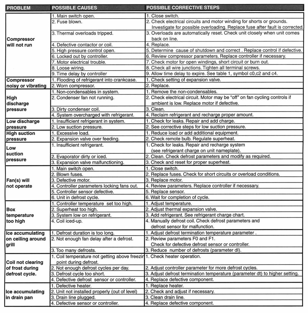
21 Troubleshooting Guide 21
22 Warranty Statement y PRINCIPAL TERMS AND CONDITIONS OF SALE 1. Applicable Law and Terms of Sale: All orders shall be subject to the following terms and conditions notwithstanding any additional or contrary printed terms and conditions of Buyer. Such additional or contrary terms shall not bind Seller unless accepted in writing even though such terms do not materially alter the terms hereof. No oral statements, warranties, stipulations, representations or terms shall have any binding effect or be any part of the contract whatsoever. 2. Orders: All orders must be in writing and will be binding when our order acknowledgment is mailed. Orders are accepted subject to strikes, fires, accidents, and other causes beyond our reasonable control. Acceptance of your order is conditioned upon an agreement to hold us harmless by reason of delivery delays. 3. Prices: Prices are subject to change without notice, and all quotations, unless otherwise specified, are binding only for immediate acceptance. Prices are based on material made to Seller's standard tolerances, unless otherwise specified. 4. Freight: All Apex units are shipped FOB Point of Shipment. Routing and selection of freight carrier will be made by Seller. For special routing requests, Buyer will bear all additional costs for such routing. Equipment is shipped at Buyer's risk. Buyer should examine equipment before signing transportation receipt. If equipment is received damaged or if quantity received does not match freight bill, the Buyer should require agent to so indicate on freight bill and immediately file a damage/missing claim. Our liability ceases upon delivery of equipment in good order to the freight carrier. 5. Taxes: Any sales, use, excise, or similar tax payable by Seller which is or may be imposed by any taxing authority upon manufacture, sale or delivery of goods covered by any order or any increase in rate of any such tax now in force, shall be added to the sales price; if not collected at the time of payment of sales price, Buyer will hold Seller harmless. 6. Limited Warranty: Seller warrants against defect in materials and workmanship in products which it manufactures for (2) year from date of installation or up to (30) thirty months from the date of shipment, whichever event occurs first, when properly installed and operated under normal use. This guarantee does not include any labor or other charges made outside of the Seller's factory for replacement or repair of defective parts unless specifically stated in the body of the Sellers invoice. On parts not manufactured by Seller, such as motors, controls, valves and compressors we extend to the Buyer the same warranties made to us by the manufacturer. Sellers only liability under this warranty or otherwise shall be the repair or replacement (at Seller's option) of non-conforming goods or parts. Seller assumes no liability for incidental or consequential damages such as injury to person or property, or lost profits. 7. THIS GUARANTEE SUPERSEDES AND IS IN LIEU OF ANY AND ALL OTHER WARRANTIES BY LAW OR CUSTOM, EITHER EXPRESSED OR IMPLIED INCLUDING, BUT NOT LIMITED BY THIS ENUMERATION, ANY GUARANTEE AS TO QUALITY OR FITNESS FOR ANY PARTICULAR PURPOSE, EXCEPT AS SET FORTH ABOVE. NO PERSON, AGENT, OR DEALER IS AUTHORIZED TO GIVE ANY WARRANTIES ON BEHALF OF SELLER NOR TO ASSUME FOR SELLER ANY OTHER LIABILITY IN CONNECTION WITH ANY OF THE SELLER'S PRODUCTS. 8. Delivery: Seller shall not be liable for any delays in or failure of delivery due to acts of God or public authority, labor disputes, accidents, fires, floods, extreme weather conditions, failure of and delays by carriers, shortages of material, delays of a supplier, and any other cause beyond Seller's control. In no event shall Seller be liable for consequential or special damages arising out of a delay in or failure of delivery. Failure to meet estimated ship dates will not be considered sufficient cause of cancellation of orders. 9. Cancellations and Returned Goods: Permission to return any part or product must be obtained from Seller and may be subject to a restocking charge. Credits for new material accepted for return will be at the original sales price or current market price, whichever is lower, less handling and restocking charges. Buyer must prepay all transportation charges. Any costs for putting material in condition for resale will be charged to the Buyer. Shipment of material returned without factory authorization or not properly tagged with a Return Material Authorization Number or that is not shipped freight-prepaid cannot be received by Seller. Obsolete products or material made to special order are not returnable. 10. Catalog Materials and Drawings: Seller is not responsible for typographical errors or other errors of omission in Seller's catalogs or drawings. 11. Late Charge Pr ovision: Buyer agrees to pay a late charge of 1-1/2% per month (18% per year) for any invoice or bill not paid within (30) thirty days of the date of the billing invoice. 12. Choices of law, Disputes: This agreement and the performance of the parties hereunder shall be construed in accordance with and governed by the laws of the State of California and shall be deemed made in the state. Buyer irrevocably consents to the exclusive jurisdiction of the courts of Orange County, California, on all matters aris ing out of or relating to this sale and Buyer further irrevocably consents to service of process by certified mail, return receipt requested, at Buyers address set froth in the order acknowledgement. The above terms and conditions apply to all orders placed with the Seller. Buyer acknowledges having read and understood these terms and conditions and agrees to abide by them upon placement of any order with the Seller. In the event it becomes necessary to refer the account to a collection agency or to institute legal action to obtain payment of the account, Buyer agrees to pay all reasonable attorney fees and court costs incurred by such action. 22
Refrigeration eration System
 Apex x PacP ackaged Refrigeration eration System INSTALLATION AND MAINTENANCE MANUAL Publication IOM H900.0 June, 005 Table of Contents Inspection Unit Placement Requirements Installation Instruction Unit
P-881 r HP KD Series DECEMBER 2015
 LIST PRICE SHEET P-881 r1 3-22 HP KD Series DECEMBER 2015 LIST PRICES 3-22 HP KD Series CONDENSING UNITS ALL PRODUCTS, EXCEPT SURFACE COILS AND PARTS, ARE SHIPPED F.O.B. POINT OF SHIPMENT WITH FULL FREIGHT
CLIMAGUARD Air-to-Air Outdoor Heat Exchangers INSTRUCTION MANUAL. Rev. H 2015 Pentair Equipment Protection P/N
 CLIMAGUARD Air-to-Air Outdoor Heat Exchangers TX23, TX33, TX38, TX52 Model INSTRUCTION MANUAL Rev. H 2015 Pentair Equipment Protection P/N 10-1008-221 87976519 TABLE OF CONTENTS RECEIVING THE HEAT EXCHANGER...3
Installation and Operations Manual
 Installation and Operations Manual H-IM-LLC February 2018 Part No. 25092501 Replaces H-IM-LLC (01/2014) Lead Lag Control System Table of Contents General Safety Information 2 Inspection 2 Warranty Statement
LIST PRICES 1/2-6 HP "KOMPACT" CONDENSING UNITS
 BULLETIN P-872r1 1-2016 SUPERSEDES 1/2-6 HP ALL PRICES PRIOR KOMPACT TO January 2016 January 2016 S 1/2-6 HP "KOMPACT" CONDENSING UNITS ALL PRODUCTS, EXCEPT SURFACE COILS AND PARTS, ARE SHIPPED F.O.B.
A PROUD HERITAGE OF EXPERIENCE & QUALITY. Beverage Cooler VT-SC-1
 A PROUD HERITAGE OF EXPERIENCE & QUALITY Beverage Cooler VT-SC-1 O W N E R S M A N U A L W W W. V I N O T E M P. C O M Your Beverage Cooler This unit can be used for Storage and/or Service. The cooler
ELECTRONIC FAUCETS INSTRUCTION MANUAL. Toll Free: (800) Haul Road Wayne, NJ krowne.
 Haul Road Wayne, NJ krowne.") ELECTRONIC FAUCETS INSTRUCTION MANUAL 100 Haul Road Wayne, NJ 07470 Toll Free: (800) 631-0442 customerservice@krowne.com krowne.com Model 16-196 1 3 2 4 6 5 7 1. 2. 3. 4. 5. 6. 7. Aerator Sensor with Cable
ELECTRONIC FAUCETS INSTRUCTION MANUAL 100 Haul Road Wayne, NJ 07470 Toll Free: (800) 631-0442 customerservice@krowne.com krowne.com Model 16-196 1 3 2 4 6 5 7 1. 2. 3. 4. 5. 6. 7. Aerator Sensor with Cable
WMWLB / WMWFM / WTWLB / WTWFM Series Hydronic Heating Unit
 January 2008 WMWLB / WMWFM / WTWLB / WTWFM Series Hydronic Heating Unit Installation Operation Maintenance The units are designed for permanent up flow, counter flow, or horizontal left or right airflow
PROAIR Water-Cooled Air Conditioner. CR43WC Model INSTRUCTION MANUAL
 PROAIR Water-Cooled Air Conditioner CR43WC Model INSTRUCTION MANUAL Rev. F 2018 nvent P/N 10-1008-167 87976466 TABLE OF CONTENTS HANDLING & TESTING THE AIR CONDITIONER...3 INSTALLATION INSTRUCTIONS...4
Installation, Operation, and Maintenance Information
 Installation, Operation, and Maintenance Information Low Velocity Unit Coolers Bulletin No. IOM 110.3 Table of Contents Inspection... 2 Installation... 2 4 General... 2 Location... 2 Drain Line... 3 Refrigerant
REFRIGERATED DROP-INS (2-6)FT-DI Installation and Operating Manual
FT-DI Installation and Operating Manual") REFRIGERATED DROP-INS (2-6)FT-DI Installation and Operating Manual For service information call 800-544-3057 Please have the following information available before calling. Information can be found on
REFRIGERATED DROP-INS (2-6)FT-DI Installation and Operating Manual For service information call 800-544-3057 Please have the following information available before calling. Information can be found on
Drop-In Refrigeration System
 Drop-In Refrigeration System Original Instructions Installation, Operation and Maintenance Manual This manual is updated as new information and models are released. Visit our website for the latest manual.
InstructIon Manual KrEs EQuIPMEnt stands
 Instruction Manual Instruction Manual SELF-CONTAINED AND REMOTE Kairak KRES model refrigerated equipment stand units are available in many lengths from 36 to 120 inches long. These units are available
OWNER S MANUAL. Installation Operation Maintenance. Saturn Equipment
 OWNER S MANUAL Saturn Stainless Steel Sandwich/Salad Table & Mega Top Refrigerators Undercounter Refrigerators & Undercounter Freezers Installation Operation Maintenance Saturn Equipment www.saturnequipment.com
TL-105 COLUMN HEATER
 TL-105 COLUMN HEATER INSTRUCTION MANUAL Timberline Instruments Inc. 1880 S. Flatiron Ct., Unit I Boulder, Colorado 80301 Ph: (303) 440-8779 Fx: (303) 440-8786 info@timberlineinstruments.com www.timberlineinstruments.com
T-SERIES Air Conditioner. T62 Model INSTRUCTION MANUAL nvent Rev. F P/N
 T-SERIES Air Conditioner T62 Model INSTRUCTION MANUAL Rev. F P/N 10-1008-239 TABLE OF CONTENTS RECEIVING THE AIR CONDITIONER... 3 HANDLING AND TESTING THE AIR CONDITIONER... 3 INSTALLATION INSTRUCTIONS...
ThermoSaver TM Hot Gas Defrost System
 PRODUCT DATA, APPLICATION & INSTALLATION GUIDE Supplement to Condensing Unit Installation and Maintenance Manual Bulletin B40-THERM-PDI-14 1069132 ThermoSaver TM Hot Gas Defrost System For use on select
POLAR TEMP FARM MORTALITY UNIT OPERATION MANUAL
 POLAR TEMP FARM MORTALITY UNIT OPERATION MANUAL www.polartemp.com TABLE OF CONTENT Disclaimer.......................................... Page 3 Inspection, unpacking and FMU setup.................. Page
MANUAL 8/12/05. Model BKP TM 100 INSTALLATION, OPERATION & MAINTENANCE. Commercial High Efficiency Heat Pipe Dehumidifier
 MANUAL 8/12/05 INSTALLATION, OPERATION & MAINTENANCE Commercial High Efficiency Heat Pipe Dehumidifier Model BKP TM 100 Heat Pipe Technology, Inc. 6904 Parke East Blvd. Tampa FL 33610 Tel: (813) 470-4250
Air Pump Up to 800 gallons
 Air Pump Up to 800 gallons REMINDER CALL 1-888-755-6750 BEFORE RETURNING TO STORE. PACKAGE CONTENTS ITEM #PBPAPK40W Questions, problems, missing parts? Before returning to your retailer, call our customer
FAN COIL NON-PROGRAMMABLE DIGITAL THERMOSTAT
 OWNER'S MANUAL FAN COIL NON-PROGRAMMABLE DIGITAL THERMOSTAT P/N E055-71520301 P/N E055-71520304 72 74 C OOL AUTO HEAT 70 2- or 4-pipe configurable Dual or Single Setpoint Very easy to program Large, easy
Blade Series Heat Exchanger Operation and Installation
 Blade Series Heat Exchanger Operation and Installation *IMPORTANT* For safe and satisfactory operation, please read the following instructions. Keep these instructions for future reference. Some information
INSTRUCTIONN MANUAL. for Angle Curved MMF9106 MMF9109 MMF9112
 INSTRUCTIONN MANUAL for Angle Curved Top Chest Freezer MMF9106 MMF9109 MMF9112 Please read this user s manual thoroughly before using. Keep this manual handy for further reference. Email: Service@atosausa.com
Standard and CELDEK Evaporative Cooler Modules Installation, Operation, and Maintenance Manual
 Standard and CELDEK Evaporative Cooler Modules Installation, Operation, and Maintenance Manual Standard Evaporative Cooler CELDEK Evaporative Cooler RECEIVING AND INSPECTION Upon receiving unit, check
CWR265SZ 26 Bottle Built-in Wine Cooler Owner s Manual
 CWR265SZ 26 Bottle Built-in Wine Cooler Owner s Manual This owner s manual provides instructions on safe installation use, and troubleshooting assistance. Please read it carefully and save it for reference
INSTRUCTION MANUAL HS-229G
 INSTRUCTION MANUAL HS-229G 510977 STEP 1 - Where to Install the Thermostatic Steam Trap Determine where to install the thermostatic steam trap based on the following information. a. The trap should be
Installation & Operation Manual Ice Cream Freezers
 Installation & Operation Manual Ice Cream Freezers Please read this manual completely before installing or operating this unit! BACF11 BACF15 Blue Air reserves the right to make product modification at
RPI Industries, Inc.
 IMPORTANT: THE FOLLOWING INFORMATION SHOULD BE RETAINED FOR FUTURE REFERENCE RPI Industries, Inc. building a better case for sales BAKERY and DELI USE AND SERVICE MANUAL WARRANTY INFORMATION SPECIFICATIONS
11,000 BTU Portable Air Conditioner with dehumidifier & Fan PE4-11R-03 Operating Instructions. Model No. PE4-11R Soleus Air International
 11,000 BTU Portable Air Conditioner with dehumidifier & Fan PE4-11R-03 Operating Instructions Model No. PE4-11R-03 2006 Soleus Air International Thank you for choosing a Soleus Air Portable Air Conditioner.
GENESIS Air Conditioner. M52 3-Phase Model INSTRUCTION MANUAL. Rev. H 2013 Pentair Equipment Protection P/N
 GENESIS Air Conditioner M52 3-Phase Model INSTRUCTION MANUAL Rev. H 2013 Pentair Equipment Protection P/N 10-1008-202 87976500 TABLE OF CONTENTS RECEIVING THE AIR CONDITIONER...3 HANDLING AND TESTING THE
Rev. E 2013 Pentair Technical Products P/N Distributed by: McLean Parts
 PROAIR Water-Cooled Air Conditioner CR43WC Model INSTRUCTION MANUAL Rev. E 2013 Pentair Technical Products P/N 10-1008-167 TABLE OF CONTENTS HANDLING & TESTING THE AIR CONDITIONER...3 INSTALLATION INSTRUCTIONS...4
UNDERCOUNTER LABORATORY REFRIGERATORS and FREEZERS Installation, Operation and Maintenance Instructions
 UNDERCOUNTER LABORATORY REFRIGERATORS and FREEZERS Installation, Operation and Maintenance Instructions INSPECTION When the equipment is received, all items should be carefully checked against the bill
T-Series Air Conditioner T53 Model
 INSTRUCTION MANUAL T-Series Air Conditioner T53 Model Protecting Electronics. Exceeding Expectations. McLean Cooling Technology 11611 Business Park Blvd N Champlin, MN 55316 USA Tel 763-323-8200 Fax 763-576-3200
Drain Cooler Water tempering device
 Water tempering device Installation instructions & user manual READ AND SAVE THESE INSTRUCTIONS DC-EN/151214 Foreword Foreword 1. These installation instructions and operation manual have been developed
Installation & Maintenance Instructions
 IMPORTANT INSTRUCTIONS READ AND SAVE THESE INSTRUCTIONS Saving energy and creating healthy, comfortable environments No. II-450 Date July, 2015 DRIVE-THRU UNIT 3 AIR CURTAIN SERIES DTU03 for outdoor use
Blue Air. Commercial Refrigeration Inc. Installation & Operation Manual Ice Cream Freezers
 Blue Air Commercial Refrigeration Inc. Installation & Operation Manual Ice Cream Freezers Please read this manual completely before installing or operating this unit! BACF11 BACF15 BACRF14 Blue Air reserves
Portable Air Conditioner 6,000 BTU 8,000 BTU 10,000 BTU
 Portable Air Conditioner 6,000 BTU 8,000 BTU 10,000 BTU OPERATING INSTRUCTIONS PCR-06-01 PCR-08-01 PCR-10-01 3058080 V170223 PURCHASE INFORMATION Thank you for choosing a Chigo Portable Air Conditioner.
T-Series Air Conditioner T20 Model
 INSTRUCTION MANUAL T-Series Air Conditioner T20 Model Protecting Electronics. Exceeding Expectations. McLean Cooling Technology 11611 Business Park Blvd N Champlin, MN 55316 USA Tel 763-323-8200 Fax 763-576-3200
MIGHTY PRO 1/4 HP CHILLER
 1 MIGHTY PRO 1/4 HP CHILLER FOR TANKS UP TO 170 GALLONS TOP QUALITY & HIGHLY EFFICIENT INTEGRATED DUAL STAGE THERMOSTAT 2 ASSEMBLY PARTS FRONT TOP VIEW BACK 3 SET UP INSTRUCTIONS 1. Remove chiller and
Model No. GB-PAC-08E4. 8,000 BTU Portable Air Conditioner Operating Instructions
 Model No. GB-PAC-08E4 8,000 BTU Portable Air Conditioner Operating Instructions Thank you for choosing a Soleus Air Powered by Gree Portable Air Conditioner. This owner s manual will provide you with valuable
Standard and CELDEK Evaporative Cooler Modules Installation, Operation, and Maintenance Manual
 Standard and CELDEK Evaporative Cooler Modules Installation, Operation, and Maintenance Manual Standard Evaporative Cooler CELDEK Evaporative Cooler RECEIVING AND INSPECTION Upon receiving unit, check
5) Do not start or stop the unit by inserting or pulling out the power plug.
 Do not start or stop the unit by inserting or pulling out the power plug.") 3058080 V170306 PURCHASE INFORMATION Thank you for choosing a Soleus Air Portable Air Conditioner. This Owner s Manual will provide you with valuable information necessary for the proper care and maintenance
3058080 V170306 PURCHASE INFORMATION Thank you for choosing a Soleus Air Portable Air Conditioner. This Owner s Manual will provide you with valuable information necessary for the proper care and maintenance
PRO 3 Top Mount Packaged Refrigeration System
 Installation and Operations Manual H-IM-81E September 2010 Part No. 25001801 PRO 3 Top Mount Packaged Refrigeration System For Indoor Applications Table of Contents 1. Owner s Installation Instructions
Installation & Operations Manual. Master-Bilt Products 908 Highway 15 North New Albany, MS Phone: (800) REV: LN PN
 REV: LN PN") Installation & Operations Manual Master-Bilt Products 908 Highway 15 North New Albany, MS 38652 Phone: (800) 684-8988 REV: LN PN 297-90000 2 TABLE OF CONTENTS INTRODUCTION.. 4 STORE CONDITIONS..... 4 WARNING
Installation & Operations Manual Master-Bilt Products 908 Highway 15 North New Albany, MS 38652 Phone: (800) 684-8988 REV: LN PN 297-90000 2 TABLE OF CONTENTS INTRODUCTION.. 4 STORE CONDITIONS..... 4 WARNING
INSTALLATION AND OPERATING MANUAL
 INSTALLATION AND OPERATING MANUAL Salad Bars Olive Bars Food Prep Cases Refrigerated Cases with Air-Over Displays Refrigerated Cases with Coppered Cold Well Displays Cases with Under-Counter Refrigerators
WIRING DIAGRAMS R410A MODELS PAC 2OAC/2OACH CAC OWC PWC
 WIRING DIAGRAMS R410A MODELS 2OAC/2OACH PAC CAC PWC OWC WIRING 02172017 TABLE OF CONTENTS PAGE 2OACH Deluxe Portable Air-cooled Heat Pump Electronic Controller... 2-3 Piping Schematic... 4 Single Phase
T-Series Air Conditioner T15 Model
 INSTRUCTION MANUAL T-Series Air Conditioner T15 Model Protecting Electronics. Exceeding Expectations. McLean Cooling Technology 11611 Business Park Blvd N Champlin, MN 55316 USA Tel 763-323-8200 Fax 763-576-3200
COMFORT PACK INSTALLATION AND MAINTENANCE INSTRUCTIONS
 R-410A - C MODELS COMFORT PACK PACKAGED THRU-THE-WALL AIR CONDITIONER WITH ELECTRIC HEAT INSTALLATION AND MAINTENANCE INSTRUCTIONS National Comfort Products 539 Dunksferry Road Bensalem, PA 19020 (215)
DBF 4XL Dryer Booster Fans
 Installation and Operation Manual Item #: 401315 Rev Date: 050814 DBF 4XL Dryer Booster Fans DBF4XL Kit Includes: Dryer Booster Fan, 1 pc Fan Mounting Bracket and Hardware, 1 pc Wall Label (Mount on wasll
Superdryer Dehumidifiers
 Superdryer Dehumidifiers Installation and Operations Manual Read and Save These Instructions Distributed Exclusively By: Air Cleaning Equipment, Inc. Broadway, NC 27505 Phone: 919-258-3330 www.aircleaningequipment.com
CELDEK Evaporative Cooler Module Installation, Operation, and Maintenance Manual. CELDEK Evaporative Cooler
 CELDEK Evaporative Cooler Module Installation, Operation, and Maintenance Manual CELDEK Evaporative Cooler RECEIVING AND INSPECTION Upon receiving unit, check for any interior and exterior damage, and
Inline Heater for Solvent or Gas. Installation and Operation Manual
 SH Series Inline Heater for Solvent or Gas Installation and Operation Manual This instruction manual explains the basic operation of the Process Technology inline solvent or gas heater. We recommend reading
T-SERIES Air Conditioner. T53 Model INSTRUCTION MANUAL nvent Rev. G P/N
 T-SERIES Air Conditioner T53 Model INSTRUCTION MANUAL Rev. G P/N 10-1008-224 TABLE OF CONTENTS RECEIVING THE AIR CONDITIONER... 3 HANDLING AND TESTING THE AIR CONDITIONER... 3 INSTALLATION INSTRUCTIONS...
INSTRUCTIONS! DO NOT DISCARD!
 INSTRUCTIONS! DO NOT DISCARD! CAUTION! Do NOT install where injury might occur due to Moving parts, Sharp corners, Hot surfaces or electrical components dcn0620 Page 1 of 12 INSTALLATION INSTRUCTIONS CAUTION
SPA BLOWER OWNER'S MANUAL XXXX, XXXX, XXXX, XXXX, XXXX, XXXX fax
 SPA BLOWER OWNER'S MANUAL 80015-XXXX, 80016-XXXX, 80017-XXXX, 80018-XXXX, 80019-XXXX, 80020-XXXX fax 888.610.3839 2015 323300-015 6/15 THIS PAGE INTENTIONALLY LEFT BLANK. 2 Operating Instructions and Parts
RPI Industries, Inc.
 IMPORTANT: THE FOLLOWING INFORMATION SHOULD BE RETAINED FOR FUTURE REFERENCE RPI Industries, Inc. building a better case for sales CONFECTIONERY USE & SERVICE MANUAL WARRANTY INFORMATION For Models Bradford
KNHE48 SERIES WATER-TO-AIR HEAT EXCHANGER
 Keep This Manual With Heat Exchanger Find additional information on this model at kooltronic.com or use the Technical Documents QR code below. Technical Documents KNHE48 SERIES WATER-TO-AIR HEAT EXCHANGER
Owner s Manual-Futura Silver Series 16 Cu. Ft. Dual Temp Refrigerator/Freezers OWNER S INSTRUCTIONS READ THIS BOOK!
 Part number 20345 Owner s Manual-Futura Silver Series 16 Cu. Ft. Dual Temp Refrigerator/Freezers OWNER S INSTRUCTIONS This manual describes how to operate and care for your appliance to get the best, most
Installation & Operations Manual Master-Bilt Products 908 Highway 15 North New Albany, MS Phone: (800)
") Installation & Operations Manual Master-Bilt Products 908 Highway 15 North New Albany, MS 38652 Phone: (800) 684-8988 6/17Rev. E 57-02410 6/17 Rev. E 57-02410 2 TABLE OF CONTENTS INTRODUCTION.... 4 STORE
Installation & Operations Manual Master-Bilt Products 908 Highway 15 North New Albany, MS 38652 Phone: (800) 684-8988 6/17Rev. E 57-02410 6/17 Rev. E 57-02410 2 TABLE OF CONTENTS INTRODUCTION.... 4 STORE
INSTRUCTION MANUAL. T-SERIES Air Conditioner. T29 Model Pentair Equipment Protection P/N McLean Parts 5736 N. Michigan Rd.
 T-SERIES Air Conditioner T29 Model INSTRUCTION MANUAL Rev. B 2013 Pentair Equipment Protection P/N 89104464 89104464 TABLE OF CONTENTS RECEIVING THE AIR CONDITIONER...3 HANDLING AND TESTING THE AIR CONDITIONER...3
KPHE24 SERIES WATER-TO-AIR HEAT EXCHANGER
 Keep This Manual With Heat Exchanger Find additional information on this model at kooltronic.com or use the Technical Documents QR code below. Technical Documents KPHE24 SERIES WATER-TO-AIR HEAT EXCHANGER
T-SERIES Air Conditioner. T29 Model INSTRUCTION MANUAL. Rev. D 2015 Pentair Equipment Protection P/N
 T-SERIES Air Conditioner T29 Model INSTRUCTION MANUAL Rev. D 2015 Pentair Equipment Protection P/N 89104464 89104464 TABLE OF CONTENTS RECEIVING THE AIR CONDITIONER...3 HANDLING AND TESTING THE AIR CONDITIONER...3
T-SERIES Air Conditioner. T50 Model INSTRUCTION MANUAL nvent Rev. F P/N
 T-SERIES Air Conditioner T50 Model INSTRUCTION MANUAL Rev. F P/N 10-1008-203 TABLE OF CONTENTS Warranty and Return Policy...2 RECEIVING THE AIR CONDITIONER...3 HANDLING AND TESTING THE AIR CONDITIONER...3
INSTRUCTION MANUAL KBD DROP-IN PAN CHILLER
 INSTRUCTION MANUAL KBD DROP-IN PAN CHILLER INSTRUCTION MANUAL KBD SELF CONTAINED AND REMOTE MODELS BLU TECHNOLOGY Kairak BLU refrigeration Drop-in Pan Chillers are designed to provide consistent, uniform
OPERATING INSTRUCTIONS
 OPERATING INSTRUCTIONS SPECIALTY REFRIGERATED TRANSPORT CABINETS FOR SATELLITE LOCATIONS RBQ-96 Caution: Read the instructions before using the machine. CONGRATULATIONS......and thank you for purchasing
SPECTRACOOL Air Conditioner. N17 Model INSTRUCTION MANUAL. Rev. G 2015 Pentair Equipment Protection P/N
 SPECTRACOOL Air Conditioner N17 Model INSTRUCTION MANUAL Rev. G 2015 Pentair Equipment Protection P/N 89117329 89117329 TABLE OF CONTENTS RECEIVING THE AIR CONDITIONER...3 HANDLING AND TESTING THE AIR
Operation Manual and Parts Directory
 Operation Manual and Parts Directory Lettuce Crisper LC Glastender, Inc. 5400 North Michigan Road Saginaw, MI 48604-9780 800.748.0423 989.752.4275 Fax 800.838.0888 / 989.752.4444 www.glastender.com Rev.
Service Manual Models CPH2 & CPH3
 Plate Heater Service Manual Models CPH2 & CPH3 888-892-2213 alluserv.com Plate Heater Service Manual Models CPH2 & CPH3 Table of Contents Introduction...................................................2
2018 Canadian Price List
 2018 Canadian Price List EC170 Series Electric Strike EC240 Series Electric Strike Prices effective February 5, 2018 2 Prices effective May 1, 2008 ASSA ABLOY, the global leader in door opening solutions
T-SERIES Air Conditioner. T29 Model INSTRUCTION MANUAL nvent Rev. I P/N
 T-SERIES Air Conditioner T29 Model INSTRUCTION MANUAL Rev. I P/N 89104464 TABLE OF CONTENTS Warranty and Return Policy...2 IMPORTANT NOTICE...2 RECEIVING THE AIR CONDITIONER...3 HANDLING AND TESTING THE
ADVANTAGE SERIES KXRP28 AIR-TO-AIR HEAT EXCHANGER
 Keep This Manual With Heat Exchanger Find additional information on this model at kooltronic.com or use the Technical Documents QR code below. Technical Documents ADVANTAGE SERIES KXRP28 AIR-TO-AIR HEAT
MN908 No. 282C Replaces 282B LB7013
 No. 282C Replaces 282B LB7013 Instruction Manual For Baldor Dust Control Units Models DC7, DC7 3, DC8, DC8 3, DC10, DC10 3, DC12, DC12 3 and DC14 3. For use on Grinders mounted to GA16 and GA20 pedestals
User s Manual & Operating Instructions
 User s Manual & Operating Instructions Model Numbers REM-03-240-GH / REM-05-240-GH CONSUMER: READ AND SAVE THESE INSTRUCTIONS Use this heater only as described in this manual. Any other use not recommended
BLG-HGP Model Bottom Mounted Full-Length Swing Glass Door Freezer Merchandisers
 Installation & Operations Manual for BLG-HGP Model Bottom Mounted Full-Length Swing Glass Door Freezer Merchandisers 2 TABLE OF CONTENTS INTRODUCTION..... 4 STORE CONDITIONS........ 4 WARNING LABELS AND
FLCH4R Garage and Utility Electric Heater
 FLCH4R Garage and Utility Electric Heater Installation, Operation & Maintenance Instructions Model No. Volts Amps Watts BTU/HR Phase High Low High Low High Low Min Fuse Size* FLCH4R 208 17.3 8.66 3600
O W N E R S M A N U A L
 A P R O U D H E R I T A G E O F E X P E R I E N C E & Q U A L I T Y B e v e r a g e C o o l e r V T - 3 2 B C S B O W N E R S M A N U A L W W W. V I N O T E M P. C O M Y o u r B e v e r a g e C o o l e
Refrigerator Freezer Installation and Operation Manual
 Speeds Up the Pace of Innovation CAUTION! PLEASE KEEP POWER SWITCH ON BEFORE OPERATING FREEZER Refrigerator Freezer Installation and Operation Manual Please read this manual completely before attempting
Portable Air Conditioner and Heater With Heat Pump Technology Operating Instructions. Model No.: PH3-12R-03 Reference No.: KY2-34
 Portable Air Conditioner and Heater With Heat Pump Technology Operating Instructions 3046364 Model No.: PH3-12R-03 Reference No.: KY2-34 Thank you for choosing a Soleus Air Portable Air Conditioner. This
Horizontal Bottle Cooler Installation and Operation Manual
 Speeds Up the Pace of Innovation Horizontal Bottle Cooler Installation and Operation Manual Please read this manual completely before attempting to install or operate this equipment! TBC-50SD, 50SB/ TBC-95SD,
WKS 4000 SERIES (USA only) --INSTALLATION INSTRUCTIONS--
 --INSTALLATION INSTRUCTIONS--") 8610 Production Avenue San Diego, California 92121 (858) 566-7465 Fax (858) 566-1943 WKS 4000 SERIES (USA only) --INSTALLATION INSTRUCTIONS-- Thank you for choosing a BREEZAIRE cooling unit. We believe
8610 Production Avenue San Diego, California 92121 (858) 566-7465 Fax (858) 566-1943 WKS 4000 SERIES (USA only) --INSTALLATION INSTRUCTIONS-- Thank you for choosing a BREEZAIRE cooling unit. We believe
T-SERIES Air Conditioner. T43 Model INSTRUCTION MANUAL nvent Rev. I P/N
 T-SERIES Air Conditioner T43 Model INSTRUCTION MANUAL Rev. I P/N 10-1008-145 TABLE OF CONTENTS Warranty and Return Policy...2 IMPORTANT NOTICE...2 RECEIVING THE AIR CONDITIONER...3 HANDLING AND TESTING
GENERAL PURPOSE REFRIGERATORS ABT-9R, ABT-14R, ABT-17R, ABT-20R, ABT-30R
 GENERAL PURPOSE REFRIGERATORS ABT-9R, ABT-14R, ABT-17R, ABT-20R, ABT-30R OWNER S INSTRUCTIONS This manual describes how to operate and care for your appliance to get the best, most efficient, performance.
INSTRUCTIONS! DO NOT DISCARD!
 INSTRUCTIONS! DO NOT DISCARD! CAUTION! Do NOT install where injury might occur due to Moving parts, Sharp corners, Hot surfaces or electrical components dn0521 Page 1 of 12 INSTALLATION INSTRUCTIONS CAUTION
Portable Air Conditioner with Evaporative Technology PE6-10R-03 Operating Instructions. Model No. PE6-10R Soleus Air International
 Portable Air Conditioner with Evaporative Technology PE6-10R-03 Operating Instructions 3046364 Model No. PE6-10R-03 2011Soleus Air International Thank you for choosing a Soleus Air Portable Air Conditioner.
Model No. PE2-07R / PE2-09R / 9000 BTU Portable Air Conditioner with dehumidifier & Fan PE2-07R-62 / PE2-09R-32 Operating Instructions
 7000 / 9000 BTU Portable Air Conditioner with dehumidifier & Fan PE2-07R-62 / PE2-09R-32 Operating Instructions 3046364 Model No. PE2-07R / PE2-09R 2006 Soleus Air International Thank you for choosing
Operator s Manual. IP-100 Immersion Probe Cooler
 Operator s Manual IP-100 Immersion Probe Cooler 110-810 04.27.11 Table of Contents Introduction... 3 General Information... 3 General Safety Information... 3 Safety Recommendations... 4 Unpacking Your
Quest Dry 150 Dual. quest Asset Protection and IAQ Solutions. Read and Save These Instructions. Installation, Operation and Maintenance Instructions
 Quest Dry 150 Dual Read and Save These Instructions This manual is provided to acquaint you with the dehumidifier so that installation, operation and maintenance can proceed successfully. Ultimate satisfaction
INSTALLATION AND OPERATING MANUAL
 INSTALLATION AND OPERATING MANUAL Refrigerated Island Merchandiser FOR PARTS & SERVICE Contact: Piper Products, Inc. Phone: (800) 544-3057 Ask for Service Department IMPORTANT! This manual contains important
INSTALLATION AND OPERATING MANUAL
 INSTALLATION AND OPERATING MANUAL Refrigerated Cases with Air-Over Displays Refrigerated High Profile Grab-N-Go FOR PARTS & SERVICE Contact: Piper Products, Inc. Phone: (800) 544-3057 Ask for Service Department
Model No.: PS08-01 PS10-01 Ref: KY80 KY100
 8,000/10,000/12,000 BTU Portable Air Conditioner Operating Instructions Model No.: PS08-01 PS10-01 Ref: KY80 KY100 Model No.: PS12-03 Ref: KY120 3119233 V160310 Thank you for choosing a Soleus Air Portable
SPECTRACOOL Air Conditioner. N21 Model INSTRUCTION MANUAL nvent Rev. G P/N
 SPECTRACOOL Air Conditioner N21 Model INSTRUCTION MANUAL Rev. G P/N 89115088 TABLE OF CONTENTS WARRANTY AND RETURN POLICY...2 RECEIVING THE AIR CONDITIONER...3 HANDLING AND TESTING THE AIR CONDITIONER...3
INSTRUCTIONS! DO NOT DISCARD!
 INSTRUCTIONS! DO NOT DISCARD! CAUTION! Do NOT install where injury might occur due to Moving parts, Sharp corners, Hot surfaces or electrical components d N0417 Page 1 of 10 INSTALLATION INSTRUCTIONS CAUTION
Installation, Operation, and Maintenance Information
 Installation, Operation, and Maintenance Information Air Cooled Condensers 8-2016 Rev 0 Table of Contents General Safety Information 2 Inspection 2 Installation 2 6 Rigging and Assembly 2 Unit Location
BX Series. Installation, Operation, Maintenance Instructions & Spare Parts
 ISO 9001 BX Series Installation, Operation, Maintenance Instructions & Spare Parts WARNING WARNING. The BX convection heater is a heavy duty baseboard designed for use in industrial environments and is
OWNER S MANUAL. Vintage Classic HEAT COOL models. Proudly Made in the USA
 OWNER S MANUAL Vintage Classic HEAT COOL models Proudly Made in the USA support@aquacomfort.com www.aquacomfort.com/service-and-support 888-475-7443 Manufacturing High Quality, High Efficiency Heat Pump
GENERAL LABORATORY REFRIGERATORS AND FREEZERS Installation, Operation and Maintenance Instructions
 GENERAL LABORATORY REFRIGERATORS AND FREEZERS Installation, Operation and Maintenance Instructions INSPECTION When the equipment is received, all items should be carefully checked against the bill of lading
Model R060 Installation - Operation Manual
 Residential Heat Pump Water Heaters Model R060 Installation - Operation Manual Important Note Read this entire manual before beginning installation Manufactured By: 6670-A Corners Industrial Court Norcross,
Operation Manual and Parts Directory
 Operation Manual and Parts Directory ST24, ST36, ST48, ST60, ST72 and ST96 Slide Top Coolers - Prior to 2009/2010* *Slide Top Cooler Serial Number Information This manual is specific to ST24, ST36, ST48,
Quick-Start Operating Guide Document No Acrylic Vacuum Chambers Copyright 2010 Terra Universal Inc. All rights reserved. Revised October 2010
 Document No. 1800-60 Acrylic Vacuum Chambers Copyright 2010 Terra Universal Inc. All rights reserved. Revised October 2010 Terra Universal, Inc. TerraUniversal.com 800 S. Raymond Ave. Fullerton, CA 92831
DEDPV-705, DEDPV-705 Hi Alt Dryer Exhaust Duct Power Ventilator (DEDPV)
") Installation and Operation Manual Item #: 483443 Rev Date: 2018-04-23 DEDPV-705, DEDPV-705 Hi Alt Dryer Exhaust Duct Power Ventilator (DEDPV) DEDPV-705 Kit Includes: Inline Fan with Integral Control, 1
Installation and Operation Manual Item #: 483443 Rev Date: 2018-04-23 DEDPV-705, DEDPV-705 Hi Alt Dryer Exhaust Duct Power Ventilator (DEDPV) DEDPV-705 Kit Includes: Inline Fan with Integral Control, 1