CWS AIR-CONDITIONERS
|
|
|
- Brianna Crawford
- 6 years ago
- Views:
Transcription
1 CWS AIR-CONDITIONERS MODUL & MODUL XL INSTALLATION, OPERATION AND MAINTENANCE MANUAL MODUL_GB_2007.doc page 1 of 28 10/04/07
2 CWS air-conditioners 1 - Installation CONTENTS 1 Installation 2 Commissioning 3 Operation Electrical connections Sea water circuit Fresh water circuit Cool mode Heat mode Fan Coil control 4 Maintenance 5 Trouble-shooting 6 Technical data 7 Electrical schematic MODUL_GB_2007.doc page 2 of 28 10/04/07
3 1.1 - Electrical connections main control panel The system is controlled by the step regulator (Thermoregulator). When the unit is running the electronic temperature control displays the actual water temperature, which is measured at the fresh water return from fan coils. The temperature control has 2 set points (ST): ST1 1 (COOL) for summer cooling at +12 C ST 2 (HEAT) for winter heating.(only for units with heat option) at +40 C. The control box is equipped with: "Control" switch ( 0-1 ) is the main switch for the units with cool mode only. OR "Mode" change over switch (COOL-OFF-HEAT) in case the system is equipped with heat function. This switch selects the running mode for summer or winter operation and in the meantime starts the unit. FLOW light (red) which lits when the fresh water flow is not enough and the safety flow switch has cut the system out. In the same time the step regulator displays a value of -6 C (Cool mode) or +60 C (Heat mode). The system will come back automatically as the fresh water flow returns to the correct value (see also 5.3) POWER light (green) which indicates that the box is connected to mains supply. RESET yellow push button used to reset the compressors safeties. The compressors will restart automatically within 6 minutes after the reset. LP, RUN and HP lights for each compressor, indicating respectively an alarm for low pressure, the run situation and the high pressure alarm on each individual compressor. Compressor "On-Off" switch to be used to cut out all or individual compressors for pump test, for limiting the system capacity. MODUL_GB_2007.doc page 3 of 28 10/04/07
.")
4 Thermoregulator step regulator which controls the fresh water temperature cutting on and off each compressor. This control has also the function to equalize the compressor running time. Main Power switch which cuts the entire supply to the electrical box The electrical box is equipped with extra connections for an external control panel (supplied as option). This panel is equipped with a On - Off switch plus the run and alarm lights and also of the mode selection (Cool-Heat) for the systems equipped of this function. In order to put the remote panel in operation, there is a specific switch inside the control box marked INT - EXT. This switch must be turned to "ext" Connections between the electrical box and the CWS unit Connect the unit main box to each module, as shown in the electrical schematic, using an adequate cable, respecting the marking in the main electrical box and in the module box. The numbering must follow the electrical schematic supplied The internal connections are: The internal connections from the main box to the individual module box are: Mains supply: check that the mains supply corresponds to the electrical box data. Controls: these are the safeties and controls from the electrical box to each single module. Each module is equipped with a connection box with a numbered terminal strip. The thermostat probe (mod. NTC) is already installed in the special pocket on the unit manifold, and must be connected as indicated in the electrical schematic. The probe cable should run separate from power cables to avoid interferences. In case of need of extending it, use a shielded cable. Do not exceed 10 metres. Connect the flow switch (no polarity)as indicated in the electrical schematic. Never run the unit without connecting the safety flow switch (see 3.2 ). MODUL_GB_2007.doc page 4 of 28 10/04/07
.")
5 External connections All the electrical connections must comply with the rules of safety existing in each country, with special care to the ground connection. Supply must be connected from a suitable circuit breaker using a cable adequate to the maximum operating load (see table C473). Also the seawater and fresh water pump lines should be done with a cable adequate to the power. Three phase compressors and pumps must be connected respecting the phase sequence of the three phases (RST). The internal connections are made respecting the phase sequence. Warning: If the phase sequence is not respected the scroll compressor will not run correctly, will be noisier and inefficient. If the scroll compressor or a pump is let run in the wrong sense for more than 5 minutes it will be damaged. Ground connection must be connected to the ground bar. MODUL_GB_2007.doc page 5 of 28 10/04/07

6 MODUL_GB_2007.doc page 6 of 28 10/04/07
7 CWS air-conditioners 1 - INSTALLATION SEA WATER CIRCUIT CONTENTS 1 Installation 2 Commissioning 3 Operation Electrical connections Sea water circuit Fresh water circuit Cool mode Heat mode Fan Coil control 4 Maintenance 5 Trouble-shooting 6 Technical data 7 Electrical schematic MODUL_GB_2007.doc page 7 of 28 10/04/07

8 1.2- SEA WATER CIRCUIT SEA WATER PUMP The seawater pump is needed to circulate the given water quantity thru the refrigerant-sea water exchanger. The seawater pump should also be quiet, continuous duty rated, marine grade material construction LOCATION Choose the pump position as per the following rules: A.- The pump should be installed with the shaft in horizontal position and the water outlet at top B the centrifugal pump must be installed at least 0.50 m below the water line C The water intake must be "scoop type" oriented forward. D Seacock, strainer and pump intake should be connected without siphoning; the piping should always rise from seacock to the pump E - The intake line should be as short as possible (it is very difficult to run a good circuit with an intake piping longer than 1 m). F The delivery side of the circuit should have the same characteristics as intake so that the circuit will be self-bleeding. G The outlet line of the pump should rise at least for 25 cm. (10 in.) just after the pump outlet in order to keep the pump primed at all times INSTALLATION The pump should be fastened with adequate screws using the holes in its base or the special fixing base (available for small models). For larger pumps, the original quiet and smooth running can be improved by using a silent block mounting SEA WATER CIRCUIT We can resume the following most important rules: the circuit should always rise from water intake to the unit manifold. After that the circuit can rise again or drop to the discharge port. It is absolutely to prevent that the circuit rises and drops making siphons, which will prevent air to be drained, causing an airlock. The discharge side of the circuit should be made so that the water discharge want cause excessive noise both for this yacht and his neighbours. We suggest having the discharge hole just above the water line, so that the water flow can be easily checked at any time. MODUL_GB_2007.doc page 8 of 28 10/04/07
9 CWS air-conditioners 1 - INSTALLATION FRESH WATER CIRCUIT CONTENTS 1 Installation 2 Commissioning 3 Operation Electrical connections Sea water circuit Fresh water circuit Cool mode Heat mode Fan Coil control 4 Maintenance 5 Trouble-shooting 6 Technical data 7 Electrical schematic MODUL_GB_2007.doc page 9 of 28 10/04/07
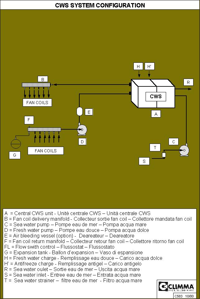
10 3 - Fresh water circuit Fresh water circuit connections Follow the installation schematic, with particular regard to the sense and position of components. Keep in mind the accessibility of components for the following steps of installation and also for maintenance. Respect the flow sense marked on the unit. Keep accessible the purging valve installed on the fresh water return. Respect the nominal diameters of the manifold. Manifold: install it in an accessible position, if possible with a certain heel (purging valve higher). Check that each calibrating valve (if installed) of the manifold is fully open. Expansion tank: respect the schematic. Connecting port must be upwards to drain out of it. Fresh water pump: respect the layout schematic. Fresh water circuit: keep in mind that the easiest and shortest is the best. Theoretically any high point in the circuit must have a purging valve. Siphoning and upand-down must be avoided as anyway they make the air purging difficult and trap air. Fan coil : respect the flow sense. Each fan coil is equipped with a purging valve that must be accessible both at installation and also for maintenance. The FC type fan coils should be installed with a backwards heeling Automatic air-bleeder This device makes much simpler both the bleeding of the new system and the following routine maintenance. It must be installed vertically on the outlet of the fresh water pump. Thie automatic air-bleeder, once the fresh water pump is primed, bleeds any air which has been trapped inside the circuit automatically. It will be necessary only to bleed the fan coils installed in the highest position as all the remaining air will be bled automatically by this device. 1.3,3 Safety Flow switch This item is installed on the fresh water manifold. It must be accessible for maintenance and calibration. The flow switch is needed as a safety device which cuts out the compressor if the fresh water circulation stops or is not enough. The flow switch must be electrically connected to the electrical box (two wires cable), as specified in the electrical schematic. The commissioning will test that this safety by simulating a reduction of the fresh water flow Pressurizing the fresh water circuit The gauge set installed in the fresh water circuit is equipped with two charging ports each ( H H1) with a manual valve and an automatic check valve, which prevents the internal charge to come back to the pressurized sanitary water circuit in case of mistake. Use one of the two valves to charge and pressurize the circuit with fresh water up to 1.5 Bars checking it with the pressure gauge. This port must be permanently connected to the yachts sanitary water system, preferably thru an additional manual valve. MODUL_GB_2007.doc page 10 of 28 10/04/07
11 Check that the circuit keeps the pressure over a certain period of time indicating that it is leak proof. As you are sure that the circuit is leak proof reduce the pressure to make room and add antifreeze to the circuit (see 3.4) Antifreeze solution We suggest two methods for filling the fresh water circuit with antifreeze: a) Calculate approximately the circuit capacity fill it with water and add to it 20% of antifreeze, using the second charging valve by gravity or using a pressure pump. Then connect the circuit to the sanitary water circuit of the vessel, pressurize up to 1.5 Bars and start purging the air. It is obvious that if purging will be difficult the percentage of antifreeze will decrease, as more water will be needed to fill the circuit, therefore more antifreeze must be added to the circuit. b) Empty the circuit from the water used for leak test. Prepare an antifreeze solution of the quantity needed to fill the circuit, made with 20% of antifreeze liquid; fill the circuit using a pressure pump. Then proceed with purging air and topping up the pressure using the solution Air bleeding We strongly recommend that a special Automatic Air bleeding vessel be installed in the fresh water circuit, just after the pump outlet. This device will dramatically reduce the bleeding procedure and will also keep the system free of air during its life. The airbleeding vessel is available in several sizes. When the circuit is under pressure with the antifreeze solution, purge the air as follows: Bleed the entire circuit (manifold, fan coils, and all the other purging points) starting from the lowest level and keeping the circuit pressure at 1.5 Bars. This bleeding must be done without running the pump. Repeat all points, until no more air comes out from the bleeding valves, still keeping the pressure at 1.5 Bars. Then... Set to off position each compressor switch. Check that seawater intake is open and start the unit in Cool mode; both pumps will run (see also 5.4). Let the fresh water pump run for 30 seconds then stop the system and bleed again all points, keeping the pressure at 1.5 Bars. During this filling procedure it is normal that the red alarm light (flow switch alarm) sometimes comes on, indicating that there is no flow in the circuit. Bleeding can be considered over when no more air is coming off the purging points and the fresh water circulation pump runs even and quiet. MODUL_GB_2007.doc page 11 of 28 10/04/07
12 MODUL_GB_2007.doc page 12 of 28 10/04/07
13 CWS air-conditioners 2 - COMMISSIONING CONTENTS 1 Installation 2 Commissioning 3 Operation Electrical connections Sea water circuit Fresh water circuit Cool mode Heat mode Fan Coil control 4 Maintenance 5 Trouble-shooting 6 Technical data 7 Electrical schematic MODUL_GB_2007.doc page 13 of 28 10/04/07
14 2 - COMMISSIONING 2.1- Fresh water circuit Important notice: The fresh water circulation must be adequate to the fan coil capacity to achieve the best performance. The flow however must reach the minimum flow specified for the central unit. The table C413 shows the values of the minimum fresh water flow. The compressor cannot run without fresh water circulation. Reduced or no water circulation will cause freezing situation and will damage the module in few seconds. If freezing happens, pure water ice will break the special heat exchanger (evaporators) of the unit, causing a complete failure of the module and or of the unit. The following safeties prevent the unit to be damaged by the lack of fresh water circulation. a) Safety flow switch: this device stops the unit if the water flow drops below the preset minimum. b) Low pressure switch: it is installed an each module and stops the unit if the low pressure in the refrigerant circuit falls below 2 bars. c) Antifreeze solution: the fresh water circuit must be filled with water and antifreeze solution (20%). The addition of antifreeze lowers the freezing point of the water and adds an additional safety to the circuit. In a freezing condition, the ice made by an antifreeze solution is softer and it will unlikely produce a damage. Antifreeze has also the purpose to prevent any corrosion inside the fresh water circuit. Check that the fresh water circuit pressure gauge shows 1.5 Bars Flow switch As explained at 3.2, a safety flow switch is installed in the fresh water circuit outlet manifold. It is very important to make sure that this safety device is properly wired to the control box. To do this, it is possible to simulate a lack of fresh water flow just pushing the lever inside the switch protecting cup. Warning : the flow switch is connected to the main electrical box and this check must be done by expert engineers only, keeping in mind all the safety precautions. 2.3 Start up Turn all the compressor switches to 0 Give supply to the electrical box and turn the Main Power switch to ON. The green LED light must come on. If the unit is equipped with the Heat function, turn the "Mode switch to "Cool" position to test the system in cool mode. OR Make sure that the box switch "Control" is in "0" position (Units without heat function). For a short time (2-3 seconds) the red warning light FLOW will come on, until it is established a regular flow in the fresh water circuit. The thermoregulator display will come on. At this stage the display will show the value of - 6 C for the cool mode and a value of + 60 C for the heat mode. This value will appear every time the unit is locked out by a flow switch alarm while the (FLOW) red light is on. The same testing procedure applies to the unit with electrical heating, taking in mind that the preset thermostat temperature is at + 40 C (104 F). The electrical heaters have a separate switch and will start instead of the compressors. Normally the number MODUL_GB_2007.doc page 14 of 28 10/04/07
15 of heaters or stages is equal to the number of compressors, but it is possible that the heaters or stages are less than compressors. The design of the Climma fan coil limits the water temperature to 50 C. It is therefore important that the preset value of the thermoregulator (ST2=45 C) is not increased Seawater circuit Check that the seawater intake is fully open and that the flow is even. 2.5 Fan coil Check that each fan coil is correctly fed with chilled water, measuring the inlet and outlet temperatures. The difference between these temperatures should be between 5 and 10 C. If the differential is higher, it normally means that there is still air in the circuit and the circulation in that fan coil is poor. In case of particularly long circuit, it might be necessary to adjust the fan coil flow closing the calibrating valves of the fan coils nearer to the manifold in order to let more water to reach the ones, which are more distant. Check that the thermostat sensor is correctly positioned in the air intake of each fan coil. If the temperature control is "Fan Only" the thermostat stops the fan when the ambient temperature reaches the set point. If the fan coil control is "Water valve" then the thermostat closes the special water valve connected to the fan coil while the fan keeps running. See special instructions for the fan coil Vega electronic infrared control are given separately. CWS air-conditioners MODUL_GB_2007.doc page 15 of 28 10/04/07
16 3 - OPERATION CONTENTS 1 Installation 2 Commissioning 3 Operation Electrical connections Sea water circuit Fresh water circuit Cool mode Heat mode Fan Coil control 4 Maintenance 5 Trouble-shooting 6 Technical data 7 Electrical schematic MODUL_GB_2007.doc page 16 of 28 10/04/07
 Put the switch (INT - EXT) in INT position. c) Turn on ON the Main Power switch. d) The POWER light (green) which indicates that the box is connected to mains supply.")
17 3 - OPERATION 3.1- Running the unit from the main control panel a) Make sure that all the circuit breakers inside the electrical box are put in ON position. b) Put the switch (INT - EXT) in INT position. c) Turn on ON the Main Power switch. d) The POWER light (green) which indicates that the box is connected to mains supply. e) Turn to 1 all the compressor switches. f) Turn the Control switch on 1 (for units in Cool Only version) OR g) Turn the."mode" change over switch (COOL -OFF-HEAT) (for units equipped with heat function), to run the system and contemporary to select the running mode (Cool). h) The FLOW light (red) will lit for a short time and then goes off meaning the the fresh water flow is correct. i) The step regulator (Thermoregulator) displays initially a value of -6 C the rises till it shows the actual fresh water temperature j) Now, one by one, all the compressors will start in sequence k) Let the system run checking that the fresh water temperature decreases regularly till it reaches the set point value. 3.2 Running the unit from the remote control panel Proceed as described in the previous chapter but at point (b) put the switch on EXT position, so that the remote panel is in control. Turn the switch of the remote panel on 1 or Cool and then proceed thru the other point till (k).. The system will work normally but it is controlled by the remote panel for MODUL_GB_2007.doc page 17 of 28 10/04/07

18 the run and stop operation and also for the Cool-Heat selection if the system has this function. 3.3 Stop from the main box: Turn the "Control or Mode switch to "0". 3.4 Stop from the remote panel Turn the remote panel switch to "0". 3.5 Pumps Pumps start as the main switch is turned into Cool or Heat mode or when the Control switch is turned to Spare pump control If there is a duty pump and a spare pump, the electrical box is equipped with a dedicated change over switch for each set of two pumps. This switch controls the use of the duty pump (position 1) or the spare pump (position 2). Before switching from position 1 to position 2, you must make the necessary changes in the sea and/or fresh water circuit, closing and opening valves in order to connect the chosen pump in the circuit. 3,7 Alarm reset In order to reset the compressor alarm it is necessary to: a) check the reasons of the alarm and restore the normal functioning conditions b) push the yellow RESET button for 5 seconds. This operation puts off the alrm lights and will restore the starting procedure, and the compressors will restart automatically within 6 minutes. 3.8 Fan coil in summer operation (standard fan coil control panel) The temperature in each cabin is controlled by a room thermostat, which controls the fan motor. The panel (Fan Coil) change over switch must be set in Sun position and the thermostat must be set to medium (horizontal setting). The fan speed control can run the fan on three different speeds. The minimum speed is in the centre of the fan control switch. 3.9 Fan coil in winter operation (standard fan coil control panel) The temperature in each cabin is controlled by a room thermostat, which controls the fan motor. The panel change over switch must be set in Ice star position and the thermostat must be set to medium (horizontal setting). The fan speed control can run the fan on three different speeds. The minimum speed is is achieved by pressing the centre of the fan control switch. MODUL_GB_2007.doc page 18 of 28 10/04/07

19 3.10 Vega Mk2 digital control The complete instructions for this control are supplied together with the product. Here under you find the simplified operation instructions. MODUL_GB_2007.doc page 19 of 28 10/04/07
20 CWS air-conditioners 4 - MAINTENANCE CONTENTS 1 Installation 2 Commissioning 3 Operation Electrical connections Sea water circuit Fresh water circuit Cool mode Heat mode Fan Coil control 4 Maintenance 5 Trouble-shooting 6 Technical data 7 Electrical schematic MODUL_GB_2007.doc page 20 of 28 10/04/07
21 4 - MAINTENANCE 4.1- Every time the unit is operated check that: 1 - With the "Control" or Mode switch on "0" all the check lights must be lit. 2 - Before turning the unit on, check that the fresh water pressure in the circuit is between 1 and 2 bars as indicated by the gauge on the unit. If the pressure drops frequently the circuit must be repaired and the leak(s) fixed as continuous topping up the pressure will dilute the antifreeze reducing the unit safety. The antifreeze solution of the Fan Coil circuit must be checked at least every 2 years. The solution to refill the circuit must be composed 80% water and 20% glycol or a good antifreeze product. 3 - Check frequently the efficiency of the seawater circuit, inspecting the seawater strainer and evaluating or even measuring the seawater flow from the outlet. We suggest keeping available a spare seal for the seawater and also one for the fresh water pump. 4 - Clean or better replace the air filters on each fan coil. A dirty air filter is dramatically reducing the fan coil efficiency as it reduces the airflow. 5 - At the beginning of the summer season, check that the condensate drain from each fan coil is clean and discharges freely. Consider that in humid and hot days the condensate can reach a flow of 1 litre per hour from each fan coil. 6 - If the system is not operated for a while, we suggest turning both pump manually for few turns before running the system. MODUL_GB_2007.doc page 21 of 28 10/04/07
22 CWS air-conditioners 5 - TROUBLESHOOTING CONTENTS 1 Installation 2 Commissioning 3 Operation Electrical connections Sea water circuit Fresh water circuit Cool mode Heat mode Fan Coil control 4 Maintenance 5 Trouble-shooting 6 Technical data 7 Electrical schematic MODUL_GB_2007.doc page 22 of 28 10/04/07
23 5 TROUBLESHOOTING 5-1 Central unit a) Red alarm light (FL) : this means that the fresh water flow in the circuit is lower than the minimum accepted. This has caused the safety flow switch to cut the unit off. This situation could be very dangerous for the unit and extreme care must be taken in investigating the reason of the cut off. Check that: The pressure in the fresh water circuit is between 1 and 2 bars The fresh water pump circuit breaker is engaged and OK and the fresh water pump is correctly turning. There is no air in the fresh water circuit. The fresh water pump shouldn't be noisy. If the system is equipped with a spare pump, make the necessary changes to the fresh water circuit, turn the pump change over switch to number "2",and run the system with the spare pump. b) Compressor alarms: Yellow lamp= low pressure: the corresponding module has been working with a pressure too low. Call service and turn this compressor switch to 0. Red lamp=high pressure: the corresponding module has been working with a pressure too high, probably due to lack of cooling water. In Summer operation: check the sea water circuit (intake, strainer and outlet) If the system is equipped with a spare sea water pump, turn the pump switch to "2" and make the necessary changes in the sea water circuit and run the system with the pump N.2. This alarm stops the sea water pump and consequently all the compressors will go off until the Reset procedure is made. In winter operation (reverse cycle): check the fresh water circuit as this pump is now cooling the condenser. Both the yellow and red lamps contemporary on: it means an intervention of the compressor internal overload safety. Call service and turn this compressor switch to 0. c) The system doesn't heat enough: All the units supplied with reverse cycle can run with seawater temperature above 10 C, which is common in the Mediterranean Sea. If the sea water temperature falls below 10 C the system should never be run as the sea water heat exchangers could be damaged by freezing Fan Coil The blower doesn't run: make sure first that the control panel is properly set to the desired "Mode" function (cool in summer and heat in winter) and that the thermostat is turned completely to " +15 " for summer operation or " +28 " for winter operation. Then check the connections. If they are OK, then test the voltage at the blower terminals with the max speed selected. The voltage must be 230V. If the voltage is correct, then the fan motor is defective and must be replaced. Give the fan coil and if possible the motor details to the service in order to get the correct spare. Be aware that the fan coil motor must run with its specified run capacitor, which is installed on its cable. If there is no voltage then check the change over switch and the thermostat on the control panel. MODUL_GB_2007.doc page 23 of 28 10/04/07
24 MODUL_GB_2007.doc page 24 of 28 10/04/07
25 CWS air-conditioners 6 - TECHNICAL DATA CONTENTS 1 Installation 2 Commissioning 3 Operation Electrical connections Sea water circuit Fresh water circuit Cool mode Heat mode Fan Coil control 4 Maintenance 5 Trouble-shooting 6 Technical data 7 Electrical schematic MODUL_GB_2007.doc page 25 of 28 10/04/07
26 6.1- TECHNICAL DATA AVERAGE FUNCTIONING VALUES COOL MODE TEMPERATURES PRESSURES Fresh water ( C) Sea water ( C) HIGH(bar) Low (bar) HIGH(psi) Low (psi) * Suction temperature + 3 C, Condensing temperature + 38 C ** Condensing temperature+ 45 C 6,2 - CWS ELECTRICAL CONNECTION DATA CWS UNIT 230/1/50 230/3/50 400/3/50 MAINS MODULE MAINS MODULE MAINS MODULE 542 S 3 x 6 3 x x 4-6* 5 x x 4-6* 5 x S 3 x 6 3 x x 6 5 x x 4-6* 5 x S 3 x 6-10* 3 x 2.5-4* 5 x 6 5 x x 4-6* 5 x S 3 x 10 3 x x 6 5 x x 6 5 x S 3 x 10 3 x 4 5 x 6 5 x x 6 5 x S 3 x 16 3 x 2.5-4* 5 x 10 5 x x 6 5 x S 5 x 16 5 x 6 5 x 6 5 x S 3 x 25 3 x 4 5 x 16 5 x x 10 5 x S 3 x 25 3 x 2.5-4* 5 x 16 5 x x 10 5 x S 5 x 16 5 x 6 5 x 10 5 x S 5 x 35 5 x 6 5 x 10 5 x S 5 x 50 5 x 6 5 x 10-16* 5 x S 5 x 50 5 x 6 5 x 16 5 x 4 * = L > 5 m. MODUL_GB_2007.doc page 26 of 28 10/04/07
27 6,3 - FAN COIL CAPACITOR TABLE MODUL_GB_2007.doc page 27 of 28 10/04/07
28 CWS air-conditioners 7 - ELECTRICAL SCHEMATICS CONTENTS 1 Installation 2 Commissioning 3 Operation Electrical connections Sea water circuit Fresh water circuit Cool mode Heat mode Fan Coil control 4 Maintenance 5 Trouble-shooting 6 Technical data 7 Electrical schematic MODUL_GB_2007.doc page 28 of 28 10/04/07
CHILLER. Modelli CWS BASIC CWS AQUACONTROL INSTALLATION MANUAL USAGE AND SCHEMATICS
 CHILLER CWS AQUACONTROL Modelli CWS BASIC 121 161 201 251 301 INSTALLATION MANUAL USAGE AND SCHEMATICS A041252 16/10/2012 COMPANY WITH QUALITY SYSTEM CERTIFIED BY DNV =ISO 9001/2000 9001/2008 = ISO VECO
INSTALLATION, COMMISSIONING AND OPERATING MANUAL
 INSTALLATION, COMMISSIONING AND OPERATING MANUAL 1 YTBV-D-CE42_0109 CONTENT Available models and capacities Supplier information Warranty Safety Emergency stops/ shutdowns About this manual Models Physical
MARINE SELF-CONTAINED DIRECT EXPANSION AIR CONDITIONING SYSTEMS
 MARINE SELF-CONTAINED DIRECT EXPANSION AIR CONDITIONING SYSTEMS Installation Manual Models : SC4.2 (Z) SC06 (Z) SC10 (Z) SC12 (Z) SC17 (Z) 2 Introduction Safety Precautions Technical Parameters Outline
Refrigeration System with a Capillary Tube and a Thermostat
 Exercise 2-1 Refrigeration System with a Capillary Tube Part A: REFRIGERATION CIRCUIT OBJECTIVE When you have completed this part, a refrigeration circuit using a capillary tube as a metering device will
1025, BOUL. MARCEL-LAURIN INSTRUCTION MANUAL FOR WATER COOLED ENVIROCHILL CHILLER. Prepared par Claude Gadoury, P. Eng MTL TECHNOLOGIES INC.
 WYETH-AYERST CANADA INC. 1025, BOUL. MARCEL-LAURIN S T - L A U R E N T, Q U É B E C INSTRUCTION MANUAL FOR WATER COOLED ENVIROCHILL CHILLER MODEL P448800LT--55WC--22C66S Prepared par Claude Gadoury, P.
Trouble Shooting Guide FAA, 3-phase (D3631)
") Trouble Shooting Guide FAA, 3-phase (D3631) Trouble Shooting Guide Problem Possible Cause Possible Remedy Unit does not start Unit does not cool No power to unit, breaker tripped Low voltage tripped Loose
Trouble Shooting Guide FAA, 3-phase (D3631) Trouble Shooting Guide Problem Possible Cause Possible Remedy Unit does not start Unit does not cool No power to unit, breaker tripped Low voltage tripped Loose
SEA FROST BD 12 OR 24 VOLT D.C. SYSTEM With Water Cooling Option
 148 OLD CONCORD TURNPIKE BARRINGTON, NH 03825 USA TEL (603) 868-5720 FAX (603) 868-1040 1-800-435-6708 E-Mail:sales@seafrost.com www.seafrost.com SEA FROST BD 12 OR 24 VOLT D.C. SYSTEM With Water Cooling
Part 3 Troubleshooting
 Part Troubleshooting What is in this part? This part contains the following chapters: Chapter See page Troubleshooting 2 Error Codes: Hydro-box 7 Error Codes: Outdoor Units Error Codes: System Malfunctions
Full Range Systems. Mokon Troubleshooting Guide Model 311. Process/Water Loop. Problem Possible Cause Corrective Measure. Process pump will not start
 Mokon Troubleshooting Guide Model 311 Process pump will not start Process pump shuts down during operation Pump seal leak Tank overflows or will not fill on systems with autofill option (water makeup valve)
Trouble Shooting Guide PWA, 3-phase (D10571)
") Trouble Shooting Guide PWA, 3-phase (D10571) Trouble Shooting Guide Problem Possible Cause Possible Remedy Unit does not start Unit does not cool No power to unit, breaker tripped Low voltage Loose wire
Trouble Shooting Guide PWA, 3-phase (D10571) Trouble Shooting Guide Problem Possible Cause Possible Remedy Unit does not start Unit does not cool No power to unit, breaker tripped Low voltage Loose wire
CHGV AIR COOLED WATER CHILLER WITH HYDRAULIC EQUIPMENT AIR / WATER 47 to 78 kw
 TECHNICAL INSTRUCTIONS CHGV AIR COOLED WATER CHILLER WITH HYDRAULIC EQUIPMENT AIR / WATER 47 to 78 kw CHGV CHGV 64 CHGV 72 CHGV 80 PHRV heat pump model also available May 2006 10 12 167 - GB - 00 MARKING
INTRODUCTION. Special Applications of Package Air Conditioners. Instant Cooling Requirement in Wedding Ceremonies
 Pakistan s Largest Manufacturers of Air-Conditioners PACKAGE TYPE UNIT FOR MOBILE APPLICATIONS Provides Turnkey Projects Conceptual Planning to Commissioning of HVACR Projects THE LARGEST MANUFACTURER
AIR COOLED CHILLERS WITH SCROLL COMPRESSORS AND CENTRIFUGAL FANS
 RAE 201 C K RAE 482 C K AIR R-407C Series RAE... C K from 19 to 83 kw - 1 and 2 circuits The air cooled chillers of RAE... C K series, with centrifugal fans, are designed for indoor installation and are
Room Air Conditioner Service and Parts Manual
 Cool Dry Temp Mode Room Air Conditioner Service and Parts Manual F Fan Speed hr Timer 0n 0ff Money Saver Fan Only Auto Swing Power CP06 CP08 93011401_01 CONTENTS 1. PREFACE 1.1 SAFETY PRECAUTIONS...2 1.2
SPECTRACOOL Air Conditioner. N21 Model INSTRUCTION MANUAL nvent Rev. G P/N
 SPECTRACOOL Air Conditioner N21 Model INSTRUCTION MANUAL Rev. G P/N 89115088 TABLE OF CONTENTS WARRANTY AND RETURN POLICY...2 RECEIVING THE AIR CONDITIONER...3 HANDLING AND TESTING THE AIR CONDITIONER...3
Vega MK 3. Instruction and Operation Manual. Annapolis MD USA
 Vega MK 3 Instruction and Operation Manual Annapolis MD USA www.veco-na.com MK3 is a control system with innovative features for Climma independent units: a) Large digital display b) Simple settings by
T-SERIES Air Conditioner. T20 Model INSTRUCTION MANUAL nvent Rev. C P/N
 T-SERIES Air Conditioner T20 Model INSTRUCTION MANUAL Rev. C P/N 89114993 TABLE OF CONTENTS Warranty and Return Policy... 2 IMPORTANT NOTICE... 2 RECEIVING THE AIR CONDITIONER... 3 HANDLING AND TESTING
T-Series Air Conditioner T15 Model
 INSTRUCTION MANUAL T-Series Air Conditioner T15 Model Protecting Electronics. Exceeding Expectations. McLean Cooling Technology 11611 Business Park Blvd N Champlin, MN 55316 USA Tel 763-323-8200 Fax 763-576-3200
Trouble Shooting Guide RAA, 1-phase (D3627)
") Trouble Shooting Guide RAA, 1-phase (D3627) Trouble Shooting Guide Problem Possible Cause Possible Remedy Unit does not start Unit does not cool No power to unit, breaker tripped Low voltage tripped Loose
Trouble Shooting Guide RAA, 1-phase (D3627) Trouble Shooting Guide Problem Possible Cause Possible Remedy Unit does not start Unit does not cool No power to unit, breaker tripped Low voltage tripped Loose
Trouble Shooting Guide PAA, 1-phase (D3731)
") Trouble Shooting Guide PAA, 1-phase (D3731) Trouble Shooting Guide Problem Possible Cause Possible Remedy Unit does not start Unit does not cool No power to unit, breaker tripped Low voltage tripped Loose
Trouble Shooting Guide PAA, 1-phase (D3731) Trouble Shooting Guide Problem Possible Cause Possible Remedy Unit does not start Unit does not cool No power to unit, breaker tripped Low voltage tripped Loose
T-SERIES Air Conditioner. T50 Model INSTRUCTION MANUAL nvent Rev. F P/N
 T-SERIES Air Conditioner T50 Model INSTRUCTION MANUAL Rev. F P/N 10-1008-203 TABLE OF CONTENTS Warranty and Return Policy...2 RECEIVING THE AIR CONDITIONER...3 HANDLING AND TESTING THE AIR CONDITIONER...3
Electrical Problems. Fuse(s) blow or circuit breaker trips. Does the unit use circuit breakers or fuses? Replace with correct fuse(s)
 blow or circuit breaker trips. Does the unit use circuit breakers or fuses? Replace with correct fuse(s)") Electrical Problems Fuse(s) blow or circuit breaker trips Does the unit use circuit breakers or fuses? Fuse(s) Circuit breakers Are the fuses dual element time delay? Is the circuit breaker HACR rated?
Electrical Problems Fuse(s) blow or circuit breaker trips Does the unit use circuit breakers or fuses? Fuse(s) Circuit breakers Are the fuses dual element time delay? Is the circuit breaker HACR rated?
Surna 25-Ton Chiller Operating & Maintenance Manual
 www.surna.com 303.993.5271 Surna 25-Ton Chiller Operating & Maintenance Manual Models: 300F3-3. 300F4-3, 300FW-3 Revised: July 2015 Table of Contents Warranty Information 4 Limited Warranty 4 Limitation
EBAC MODEL AD850 INDUSTRIAL DEHUMIDIFIER OWNER S MANUAL
 EBAC MODEL AD850 INDUSTRIAL DEHUMIDIFIER OWNER S MANUAL Ebac Industrial Products 704 Middle Ground Boulevard Newport News VA 23606 Telephone (757) 873-6800 FAX (757) 873-3632 Website: www.ebacusa.com INTRODUCTION
SHURFLO BLASTER II MARINE WASHDOWN PUMP PRODUCT TECHNICAL DATA SHEET
 SHURFLO BLASTER II MARINE WASHDOWN PUMP PRODUCT TECHNICAL DATA SHEET OEM: AFTERMARKET: 8-11-A07 8-11-E07 APPLICATION: Marine fresh or salt water wash-down installation. This pump may be used for general
TECHNICAL GUIDE DESCRIPTION SPLIT-SYSTEM AIR-COOLED CONDENSING UNITS MODELS: HF-07 FEATURES B-0703
 TECHNICAL GUIDE SPLIT-SYSTEM AIR-COOLED CONDENSING UNITS MODELS: HF-07 DESCRIPTION These Sunline 2000 units are completely assembled, piped and wired at the factory to provide one-piece shipment and rigging.
Bulletin (Jan 2011) And User s Guide
 And User s Guide") Bulletin 30 32 (Jan 2011) Unichiller Installation And User s Guide Customer Service If you have questions about Installation, operation and Maintenance of the Unichiller or would like to order replacement
Bulletin 30 32 (Jan 2011) Unichiller Installation And User s Guide Customer Service If you have questions about Installation, operation and Maintenance of the Unichiller or would like to order replacement
Operation & Maintenance Manual
 Operation & Maintenance Manual VUD, VUF, VDF & HCD Series Unit Ventilator IMPORTANT: Read and save this manual for future reference. This manual is to be left with the equipment owner 2006 TEMSPEC INCORPORATED
T-SERIES Air Conditioner. T29 Model INSTRUCTION MANUAL nvent Rev. I P/N
 T-SERIES Air Conditioner T29 Model INSTRUCTION MANUAL Rev. I P/N 89104464 TABLE OF CONTENTS Warranty and Return Policy...2 IMPORTANT NOTICE...2 RECEIVING THE AIR CONDITIONER...3 HANDLING AND TESTING THE
Owners Manual UA75 TO UA1200 SERIES Refrigerated Air Dryer
 1 Owners Manual UA75 TO UA1200 SERIES Refrigerated Air Dryer DESCRIPTION PAGE INTRODUCTION 2 INSTALLATION 3 INSTALLATION GUIDE 4 DRYER CONTROLS 5 DRYER CONTROLS AND SAFTEY SHUTDOWNS 6 START UP 6 INITIAL
AIR COOLED CHILLERS WITH SCROLL COMPRESSORS AND CENTRIFUGAL FANS
 RAE 1402 C O K AIR R-407C Series RAE... C K Cooling capacity from 81 to 250 kw - 2 circuits The air cooled chillers of RAE C K series, with centrifugal fans, are designed for indoor installation and are
T-SERIES Air Conditioner. T43 Model INSTRUCTION MANUAL nvent Rev. I P/N
 T-SERIES Air Conditioner T43 Model INSTRUCTION MANUAL Rev. I P/N 10-1008-145 TABLE OF CONTENTS Warranty and Return Policy...2 IMPORTANT NOTICE...2 RECEIVING THE AIR CONDITIONER...3 HANDLING AND TESTING
T-Series Air Conditioner T20 Model
 INSTRUCTION MANUAL T-Series Air Conditioner T20 Model Protecting Electronics. Exceeding Expectations. McLean Cooling Technology 11611 Business Park Blvd N Champlin, MN 55316 USA Tel 763-323-8200 Fax 763-576-3200
Table of Contents. Service Procedures. Service Procedures. Measuring Superheat (4) Measuring Subcooling (5) Airflow Calculation (6-8)
 Measuring Subcooling (5) Airflow Calculation (6-8)") Table of Contents Refrigeration Cycle Service Procedures Measuring Superheat (4) Measuring Subcooling (5) Airflow Calculation (6-8) Solving Problems Identifying Low System Charge (9-11) Identifying High
Table of Contents Refrigeration Cycle Service Procedures Measuring Superheat (4) Measuring Subcooling (5) Airflow Calculation (6-8) Solving Problems Identifying Low System Charge (9-11) Identifying High
PRE-ASSEMBLED RADIANT CONTROL PANEL INSTALLATION MANUAL
 FloorHeat PRE-ASSEMBLED RADIANT CONTROL PANEL INSTALLATION MANUAL Thank you for purchasing this radiant control panel assembly. Following are some important notes that will make the installation successful.
INSTRUCTION AND MAINTENANCE MANUAL DRYERS A 11 - A 12 - A 13 - A 14 (R410A)
") Code 007806 0 Edit. 0/04 INSTRUCTION AND MAINTENANCE MANUAL DRYERS A - A - A - A 4 (R40A) READ THIS MANUAL CAREFULLY BEFORE CARRYING OUT ANY OPERATIONS ON THE DRYER. Cod. 007806 0 - Edition 0/04 - CONTENTS
Code 007806 0 Edit. 0/04 INSTRUCTION AND MAINTENANCE MANUAL DRYERS A - A - A - A 4 (R40A) READ THIS MANUAL CAREFULLY BEFORE CARRYING OUT ANY OPERATIONS ON THE DRYER. Cod. 007806 0 - Edition 0/04 - CONTENTS
Prodigy Eclipse Cuber Technical Training
 Prodigy Eclipse Cuber Technical Training 600 800 1000 1200 1400 1800 2000 In This Presentation What Eclipse is Components and their functions Installation Operation Maintenance Service Diagnosis The Prodigy
WALLACE MAXIPUMP 3000, 5000, 6000 and HYDROJET 30P, 30C, 140 AND HJ400 INSTALLATION AND MAINTENANCE INSTRUCTIONS
 6 th June 2006 Page 1 WALLACE MAXIPUMP 3000, 5000, 6000 and HYDROJET 30P, 30C, 140 AND HJ400 INSTALLATION AND MAINTENANCE INSTRUCTIONS Please read and follow all these instructions carefully before proceeding
peaksaver PLUS Program
 THERMOSTAT TROUBLESHOOTING Blank Screen 1. Make sure that the furnace power is turned on at the breaker panel and ensure fuses are not blown. (Having extra proper-size fuses on hand is a good idea.) 2.
Scotsman Technical Training. CU50 Cube Ice Machine
 Scotsman Technical Training CU50 Cube Ice Machine Major Topics Overview Installation Start Up Sequence of Operation Maintenance Diagnostics Service Procedures Models Two Base Models Gravity Drain Pump
CLIMATE AND WATER MAKERS. Chap. Desalination Purifiers Self contained units Split units. -
 CLIMATE AND WATER MAKERS Desalination Purifiers Self contained units Split units You can consult this chapter even with your mobile device. www.rebamarine.com - reba@rebamarine.com 419 WATERMAKER PROGRESS
Operation Manual SCT14B and SCT18B. Inspection. 3 General Description. 3 General Requirements. 3 Standard Features.
 Spot Cooling Systems, Inc. 120 Century Drive Suite 00 Carrollton, TX 7006 00-6-776 Operation Manual SCT1B and SCT1B Warning! Improper installation, adjustment, alteration, service, or maintenance can cause
NON-CYCLING REFRIGERATED AIR/GAS DRYERS QPNC 75 to QPNC 250 OPERATOR S MANUAL
 NON-CYCLING REFRIGERATED AIR/GAS DRYERS QPNC 75 to QPNC 250 OPERATOR S MANUAL DATE OF PURCHASE: MODEL: SERIAL NO.: Record above information from nameplate. Retain this information for future reference.
ULTIMATE ENERGY SAVING TECHNOLOGY
 ULTIMATE ENERGY SAVING TECHNOLOGY CWM CHILLER SERIES CWM PURESTREAM SERIES WATER CHILLERS The new CWM Purestream chiller range is specifically designed to meet the stringent cooling requirements of today
CB 8000 AMBIENT AIR CONDITIONED FRESH AIR SUPPLY SYSTEM OPERATOR S MANUAL
 TENNESSEE CHILL BOX, LLC 9909 Blue Springs Road Harrison, Tn 37341 423-710-1476 CB 8000 AMBIENT AIR CONDITIONED FRESH AIR SUPPLY SYSTEM OPERATOR S MANUAL Thank you for choosing the CHILL BOX, a unique,
T-Series Air Conditioner T53 Model
 INSTRUCTION MANUAL T-Series Air Conditioner T53 Model Protecting Electronics. Exceeding Expectations. McLean Cooling Technology 11611 Business Park Blvd N Champlin, MN 55316 USA Tel 763-323-8200 Fax 763-576-3200
OWNER S MANUAL Manufactured Home Downflow Gas Furnace: MGD-B Series
 OWNER S MANUAL Manufactured Home Downflow Gas Furnace: MGD-B Series Heat Controller, Inc. 1900 Wellworth Ave. Jackson, MI 49203 (517)787-2100 www.heatcontroller.com Owner s Manual MGD-B SERIES GAS FURNACE
SERVICING PROCEDURE R-410A LEAK TEST EVACUATION CHARGING. Bard Manufacturing Company, Inc. Bryan, Ohio Manual Page 1 of 11
 SERVICING PROCEDURE R-410A LEAK TEST EVACUATION CHARGING Bard Manufacturing Company, Inc. Bryan, Ohio 43506 Since 1914...Moving ahead, just as planned. Manual No.: 2100-479 Supersedes: NEW File: Volume
ENGLISH. Dometic Environmental Corporation. Rev L-2484
 DOMETIC TURBO DIRECT EXPANSION AIR CONDITIONING SYSTEMS INSTALLATION MANUAL Dometic Environmental Corporation Rev. 5-30-07 L-2484 DOMETIC TURBO DX AC INSTALLATION MANUAL CONTENTS Introduction 4 Installation
EXTREME HC-8 Reverse Osmosis System
 EXTREME HC-8 Reverse Osmosis System Leader Evaporator Co., Inc. 49 Jonergin Drive Swanton, VT 05488 Tel: 802-868-5444 www.leaderevaporator.com TABLE OF CONTENTS INTRODUCTION... 4 THEORY OF OPERATION...
Owner s Manual for Swimming Pool Heat Pump
 Owner s Manual for Swimming Pool Heat Pump FC Series nirvanahp.com CONTENTS How it works 1 Installation 2 3 Settings 4 5 6 7 Start-up 8 Winterizing 9 Maintenance 10 Troubleshooting 11 12 13 Warranty 14
Freightliner Refrigerator Troubleshooting Guide For (TJ18F) (TJ22F) (TJ18FP3)
 (TJ22F) (TJ18FP3)") www.dometic.com Freightliner Refrigerator Troubleshooting Guide For Before initiating troubleshooting, the following equipment is recommended: Multimeter, 20 gauge (min) wires to use as jumpers, and 12Vdc
www.dometic.com Freightliner Refrigerator Troubleshooting Guide For Before initiating troubleshooting, the following equipment is recommended: Multimeter, 20 gauge (min) wires to use as jumpers, and 12Vdc
Method to test HVAC equipment at part load conditions
 IPLV Method to test HVAC equipment at part load conditions For water cooled chillers: 100% load ( % hrs) + 75% ( Hrs ) + 50% ( Hrs ) + 25% ( Hrs ) = IPLV value Manufacturer can favor this number by tweaking
NON-SUBMERSIBLE WATER PUMP
 NON-SUBMERSIBLE WATER PUMP MODEL NO: CEB103 PART NO: 7230327 OPERATION & MAINTENANCE INSTRUCTIONS LS0114 INTRODUCTION Thank you for purchasing this CLARKE Water Pump, which is a general purpose pump, suitable
Refrigerant Recovery Unit, Model RRU134
 Installation, Operation & Maintenance Manual IOMM RRU134 Group: Refrigerant Effective: December 2000 Supersedes: New Refrigerant Recovery Unit, Model RRU134 1999 McQuay International Table of Contents
NEWGATE TECHNOLOGIES, INC.
 www W.newgatetechnologies.com NEWGATE TECHNOLOGIES, INC. Installation & Operations Manual SYNERGY Series High Inlet Temperature Refrigerated Air Dryers Models SYNERGY 025 ~ SYNERGY 125 Includes Safety
PROAIR Air Conditioner. CR29 Model INSTRUCTION MANUAL nvent Rev. I P/N
 PROAIR Air Conditioner CR29 Model INSTRUCTION MANUAL Rev. I P/N 89104461 TABLE OF CONTENTS Warranty and Return Policy...2 RECEIVING THE AIR CONDITIONER...3 HANDLING AND TESTING THE AIR CONDITIONER...3
OWNER S MANUAL. Models: AC110, AC125, AC150 made from 2003 through Proudly Made in the USA
 OWNER S MANUAL Models: AC110, AC125, AC150 made from 2003 through 2010 Proudly Made in the USA support@aquacomfort.com www.aquacomfort.com/service-and-support/ (888) 475-7443 Manufacturing High Quality,
MAXI PUMP INSTRUCTION MANUAL NE6151B /NE6171B READ THIS MANUAL CAREFULLY BEFORE USING YOUR MAXI PUMP
 MAXI PUMP INSTRUCTION MANUAL NE6151B /NE6171B READ THIS MANUAL CAREFULLY BEFORE USING YOUR MAXI PUMP 8104 MAXI-PUMP PARTS BREAKDOWN Re f # 1 2 3 4 5 6 7a 7b 8 9 10 11 12 13 14 15 16 2 Part # NEP2134 NEP2135
Commissioning a Solar Thermal Installation
 OPERATING INSTRUCTIONS Wagner& Co Commissioning a Solar Thermal Installation Contents. Solar Circuit... 2. Commissioning... 3 3. Service Information... 4. Maintenance.... Solar Circuit Components Pipework
Technical Review. Remote Condenser Cuber. Enhanced Refrigeration and Water Systems. CM 3 Technology. of a. with. using. models included are:
 Technical Review of a Remote Condenser Cuber with Enhanced Refrigeration and Water Systems using CM 3 Technology models included are: CME1356 shown on BH900 CME456, CME1056, CME1356, CME1656 and CME2006
Instruction manual Harmo PAC ZVWX1017/1022/1032/1041/1055/1056/1061
 Instruction manual Harmo PAC ZVWX1017/1022/1032/1041/1055/1056/1061 Imported by: Zwembad BVBA Industrieweg 9 3190 Boortmeerbeek België www.harmopool.eu 0 Table of content Introduction... 2 Safety instructions...
INSTALLER: PLEASE LEAVE THIS MANUAL FOR THE OWNER S USE. Condensate Return Systems General Installation, Operation, & Service Instructions !
 Condensate Return Systems General Installation, Operation, & Service Instructions INSTALLER: PLEASE LEAVE THIS MANUAL FOR THE OWNER S USE. SAFETY INSTRUCTIONS This safety alert symbol will be used in this
CWA2 Chilled Water Fan Coil With or Without Electric Heat 2-Pipe Heat / Cool Fan Coil 18,000-60,000 BTUH
 CWA2 Chilled Water Fan Coil With or Without Electric Heat 2-Pipe Heat / Cool Fan Coil 18,000-60,000 BTUH 233 CWA2 NOMENCLATURE BREAKDOWN 2-Pipe Heat/Cool with Electric Heat Multiposition Fan Coil Nominal
Installation, Operation & Maintenance Manual for MCW Chillers Using the DDC Digital Diagnostic Control 8/04 L-2164
 mcw chiller Installation, Operation & Maintenance Manual for MCW Chillers Using the DDC Digital Diagnostic Control 8/04 L-2164 PREFACE Congratulations on the purchase of your air conditioning chilled water
Advance Release September 2009
 Vertical Air Cooled DSV Series R 410A Model DSV096 DSV120 DSV144 DSV180 Nominal Cooling (Tons) 8 10 12 15 Refrigerant R 410A R 410A R 410A R 410A Cooling Performance Gross Cooling Capacity(Btu/h) 95,000*
SEA FROST BD 12 OR 24-VOLT D.C. AIR-COOLED SYSTEM
 148 OLD CONCORD TURNPIKE BARRINGTON, NH 03825 USA TEL (603) 868-5720 FAX (603) 868-1040 1-800-435-6708 E-Mail:sales@seafrost.com www.seafrost.com SEA FROST BD 12 OR 24-VOLT D.C. AIR-COOLED SYSTEM CONDENSING
OWNER S MANUAL. Vintage Classic HEAT COOL models. Proudly Made in the USA
 OWNER S MANUAL Vintage Classic HEAT COOL models Proudly Made in the USA support@aquacomfort.com www.aquacomfort.com/service-and-support 888-475-7443 Manufacturing High Quality, High Efficiency Heat Pump
OWNERS INSTRUCTION MANUAL FOR FIXED INSTALLATION COMMERCIAL AND RESIDENTIAL EVAPORATIVE AIR CONDITIONERS
 R O O F T O P N A T U R A L A I R C O N D I T I O N E R S OWNERS INSTRUCTION MANUAL FOR FIXED INSTALLATION COMMERCIAL AND RESIDENTIAL EVAPORATIVE AIR CONDITIONERS How to Operate Using Your Air Conditioner
passport I/O controls
 passport I/O controls Operation Manual DIRECT EXPANSION SYSTEMS Revised: 9-18-07 L-2231 Table of Contents Passport I/O Controls Introduction 4 Standard Features...4 Optional Features...4 Overview...4
MDX. Non-Cycling Refrigerated Compressed Air Dryers with zero-loss Intellidrain Drain Trap. Operation & Maintenance Manual MDX MODELS 18 THRU 250
 MDX Non-Cycling Refrigerated Compressed Air Dryers with zero-loss Intellidrain Drain Trap Operation & Maintenance Manual MDX MODELS 18 THRU 250 TABLE OF CONTENTS HOW TO USE THIS MANUAL 2 SYMBOLS 2 WARRANTY
Refrigeration Controller Operator s Manual (HRC) PO Box 6183 Kennewick, WA
 PO Box 6183 Kennewick, WA") Refrigeration Controller Operator s Manual (HRC) PO Box 6183 Kennewick, WA 99336 www.jmcvr.com 1-509-586-9893 Table of Contents TABLE OF FIGURES...1 OVERVIEW OF THE HRC CAPABILITIES...2 INSTALLATION AND
Refrigeration Controller Operator s Manual (HRC) PO Box 6183 Kennewick, WA 99336 www.jmcvr.com 1-509-586-9893 Table of Contents TABLE OF FIGURES...1 OVERVIEW OF THE HRC CAPABILITIES...2 INSTALLATION AND
ENERGY LIGHT USER S GUIDE ENERGY LIGHT USER S GUIDE
 ENERGY LIGHT USER S GUIDE Release January 2001 CONTENTS 1.0 GENERAL CHARACTERISTICS... 4 1.1 MAIN CHARACTERIS TICS... 4 2.0 USER INTERFACE (CODE C5121230)... 5 2.1 DISPLAY... 5 2.2 MEANING OF THE LEDS...
2 SPEED PUMP INSTRUCTION MANUAL READ THIS MANUAL CAREFULLY BEFORE USING YOUR 2 SPEED PUMP
 2 SPEED PUMP INSTRUCTION MANUAL READ THIS MANUAL CAREFULLY BEFORE USING YOUR 2 SPEED PUMP 8308 PUMP PARTS BREAKDOWN Ref # Part # Manf. # Descrip on 1 NEP2134 AC 81361 PUMP LID 2 NEP2135 AC 81396 PUMP LID
PROAIR Air Conditioner. CR23 Model INSTRUCTION MANUAL nvent Rev. D P/N
 PROAIR Air Conditioner CR23 Model INSTRUCTION MANUAL Rev. D P/N 89112522 TABLE OF CONTENTS Warranty and Return Policy...2 RECEIVING THE AIR CONDITIONER...3 HANDLING AND TESTING THE AIR CONDITIONER...3
RAS Kp AIR COOLED CHILLERS WITH RECIPROCATING COMPRESSORS AND AXIAL FANS REFRIGERANT R290 LIQUID CHILLERS - AIR COOLED AIR
 AIR COOLED CHILLERS WITH RECIPROCATING COMPRESSORS AND AXIAL FANS REFRIGERANT R290 46 Above picture is only indicative and is not binding AIR FC The packaged air cooled chillers of RAS Kp series are suitable
Q&A 2016 Practical Guide
 Q&A 2016 Practical Guide A guide made to help you! Do not hesitate to consult this Q&A before sending a service call request to Waterco Canada Inc. Service: 450.748.6002 / 1.888.796.6002 Fax: 450.748.4365
Dometic Digital Control (for DX systems)
") Dometic Digital Control (for DX systems) OPERATIONS MANUAL Dometic Marine Rev. 20090220 L-2658 English COPYRIGHT 2007-2009 Dometic Marine. All Rights Reserved. No part of this publication may be reproduced,
Dometic Digital Control (for DX systems) OPERATIONS MANUAL Dometic Marine Rev. 20090220 L-2658 English COPYRIGHT 2007-2009 Dometic Marine. All Rights Reserved. No part of this publication may be reproduced,
TWLC - Tempered Water Logic Controller. The Intelligent Control
 TWLC - Tempered Water Logic Controller The Intelligent Control Chiller Controls Features: Up to six (6) stages: individual board for each stage maximizes redundancy. Menu driven access and programming.
CWA4 Chilled & Hot Water Fan Coil
 CWA4 Chilled & Hot Water Fan Coil 4-Pipe Heat & Cool Fan Coil 24,000-60,000 BTUH 259 CWA4 NOMENCLATURE BREAKDOWN 4-Pipe Heat & Cool Multiposition Fan Coil Nominal BTUH 24=24,000 36=36,000 48=48,000 60=60,000
HT V2 HT Split
 Scroll compressor Refrigerant R07C Aqu@Scop HT V Aqu@Scop HT Split High Temperature Air-to-Water Heat Pumps Models -, -7 and 8-9.0 to 7.9kW Aqu@Scop HT V / Aqu@Scop HT Split Installation examples - Single
TQ Series. Electronic Control Pump Instruction Manual. 50Hz. ISO 9001 Certified Walrus Pump Co., Ltd.
 TQ Series Electronic Control Pump Instruction Manual 50Hz ISO 9001 Certified Walrus Pump Co., Ltd. EC Declaration of Conformity Manufacturer: Walrus Pump Co., Ltd. Address: No. 83-14, Dapiantou, Sanjhih
CHILLER. Model CH3000. Operator s & Installation Manual
 CHILLER Model CH3000 Operator s & Installation Manual Release Date: February 14, 2011 Publication Number: 620054173OPR Revision Date: May 08, 2014 Revision: B Visit the Cornelius web site at www.cornelius.com
OPERATION AND MAINTENANCE INSTRUCTIONS FOR ROOF TOP HEAT PUMPS AND CEILING PLENUMS
 OPERATION AND MAINTENANCE INSTRUCTIONS FOR ROOF TOP HEAT PUMPS AND CEILING PLENUMS TABLE OF CONTENTS I. General Information.................................................. 2 II. Standard Ceiling Plenum
passport I/O controls
 passport I/O controls Operation Manual DIRECT EXPANSION SYSTEMS Revised: 11-7-05 L-2231 Table of Contents 1.0 Passport I/O Controls Introduction 4 1.01 Standard Features... 4 1.02 Optional Features...
Series 9. Commissioning Checklist. MISSION CRITICAL Air Conditioning Systems. ClimateWorx International Inc.
 MISSION CRITICAL Air Conditioning Systems Series 9 Commissioning Checklist S9-CL2017.doc ClimateWorx International Inc. 14 Chelsea Lane, Brampton, Ontario, Canada L6T 3Y4 2 S9-CL2017.doc Commissioning
DTW Works Master Specification Version 2006 Issued 2006/08/01 Section15621 Packaged Reciprocating Water Chillers Page 1 of 5
 Issued 2006/08/01 Section15621 Packaged Reciprocating Water Chillers Page 1 of 5 PART 1 GENERAL 1.1 RELATED SECTIONS.1 Section 01330 Submittal Procedures..2 Section 01355 Waste Management and Disposal..3
EXTREME HC-4 Reverse Osmosis System Leader Evaporator Co., Inc. 49 Jonergin Drive Swanton, VT Tel:
 [Type a quote from the document or the summary of an interesting point. You can position the text box anywhere in the document. Use the Drawing Tools tab to change the formatting of the pull quote text
AIR COOLED FREE-COOLING CHILLERS WITH SCROLL COMPRESSORS AND AXIAL FANS
 RAE 1352 F.K + MV AIR R-407C FC Series RAE... F.K Cooling capacity from 77 to 289 kw - 2 circuits The air cooled chillers of RAE... F.K series, are designed for outdoor installation and are particularly
Tempered Water Logic Control OPERATION l TROUBLE SHOOTING
 Tempered Water Logic Control OPERATION l TROUBLE SHOOTING English For MPE Multiple Chiller Units Control Panel TEMPERED WATER SYSTEMS L-2199 Rev. 20080223 Revision: L-2199 20101104 *** IMPORTANT NOTICE
GLYCOL CHILLER INSTRUCTIONS IMPORTANT: BEFORE OPERATING PLEASE SEE INSTRUCTIONS ON PAGE 5
 GLYCOL CHILLER INSTRUCTIONS IMPORTANT: BEFORE OPERATING PLEASE SEE INSTRUCTIONS ON PAGE 5 CONTENTS Key features...p.1 Product contents...p.1 Safety information...p.2 Maintenance...p.2 How it works...p.5
INSTALLATION AND TROUBLE SHOOTING MANUAL for all Models of Nova Kool Remote Condensing units & Cold plates.
 INSTALLATION AND TROUBLE SHOOTING MANUAL for all Models of Nova Kool Remote Condensing units & Cold plates. Thank you for choosing Nova Kool for your refrigeration needs. For over 20 years we have been
TIDALWAVE I/G POOL PUMP INSTRUCTION MANUAL
 TIDALWAVE I/G POOL PUMP INSTRUCTION MANUAL READ THIS MANUAL CAREFULLY BEFORE USING YOUR PUMP 88 PUMP PARTS BREAKDOWN REF # Order # Mfr # Description 1 NEP4 AC 348 Lid Knobs NEP AC 380 Strainer Lid 3 NEP6
EXTREME HC-2 Reverse Osmosis System
 EXTREME HC-2 Reverse Osmosis System Leader Evaporator Co., Inc. 49 Jonergin Drive Swanton, VT 05488 Tel: 802-868-5444 www.leaderevaporator.com Contents INTRODUCTION... 3 THEORY OF OPERATION... 4 Terms...
Automatic Ice maker. Service manual MIM250
 Automatic Ice maker Service manual MIM250 1 Table of contents Installation Guidelines ---------------------------------------------------------3 How the Ice Maker Works ----------------------------------------------------4
Refrigerator KE T
 Refrigerator KE 680-1-3T Service Manual: H8-74-07 Responsible: U. Laarmann KÜPPERSBUSCH HAUSGERÄTE AG E-mail: uwe.laarmann@kueppersbusch.de Tel.: (0209) 401-732 Customer Service Fax: (0209) 401-743 Postfach
PHOENIX 200 MAX. 1 Specifications. 2 Operation. Therma-Stor Products. Phoenix 200 Max Operation & Service Instructions
 PHOENIX 200 MAX LOW GRAIN REFRIGERANT HIGH CAPACITY DEHUMIDIFIER Table of Contents Therma-Stor Products Box 8050 Madison, WI 53708 Toll Free 1-800-533-7533 Local 1-608-222-5301 Phoenix 200 Max Operation
SYSTEM 2000 CHILLED WATER (CAC) EC SERIES -INSTALLATION OPERATIONS AND MAINTENANCE MANUAL-
 EC SERIES -INSTALLATION OPERATIONS AND MAINTENANCE MANUAL-") SYSTEM 2000 CHILLED WATER (CAC) EC SERIES -INSTALLATION OPERATIONS AND MAINTENANCE MANUAL- 8167 Byron Road Whittier, CA 90606 Phone: (562) 945-8971 Fax: (562) 696-0724 www.compu-aire.com Table of Contents
SYSTEM 2000 CHILLED WATER (CAC) EC SERIES -INSTALLATION OPERATIONS AND MAINTENANCE MANUAL- 8167 Byron Road Whittier, CA 90606 Phone: (562) 945-8971 Fax: (562) 696-0724 www.compu-aire.com Table of Contents
CHG AIR COOLED WATER CHILLER WITH CONDENSATION BY HELICOIDAL AIR 8 to 17 kw
 TECHNICAL INSTRUCTIONS CHG AIR COOLED WATER CHILLER WITH CONDENSATION BY HELICOIDAL AIR 8 to 17 kw CHG 1 CHG 1 8. kw. kw.7 kw 1. kw April 7 19 - GB - 2 MARKING This product marked conforms to the essential
The Book of AERMEC NRL Sequence of Operation
 The Book of AERMEC NRL Sequence of Operation Heating and cooling operation. 2 Sequence of operation Aermec air to water chiller/heat pump use Hydronic s in conjunction with refrigerant to provide heating